WO2018168389A1 - Vehicle control apparatus - Google Patents
Vehicle control apparatus Download PDFInfo
- Publication number
- WO2018168389A1 WO2018168389A1 PCT/JP2018/006568 JP2018006568W WO2018168389A1 WO 2018168389 A1 WO2018168389 A1 WO 2018168389A1 JP 2018006568 W JP2018006568 W JP 2018006568W WO 2018168389 A1 WO2018168389 A1 WO 2018168389A1
- Authority
- WO
- WIPO (PCT)
- Prior art keywords
- regenerative
- energy
- vehicle
- engine
- traveling
- Prior art date
Links
Images


Classifications
-
- B—PERFORMING OPERATIONS; TRANSPORTING
- B60—VEHICLES IN GENERAL
- B60L—PROPULSION OF ELECTRICALLY-PROPELLED VEHICLES; SUPPLYING ELECTRIC POWER FOR AUXILIARY EQUIPMENT OF ELECTRICALLY-PROPELLED VEHICLES; ELECTRODYNAMIC BRAKE SYSTEMS FOR VEHICLES IN GENERAL; MAGNETIC SUSPENSION OR LEVITATION FOR VEHICLES; MONITORING OPERATING VARIABLES OF ELECTRICALLY-PROPELLED VEHICLES; ELECTRIC SAFETY DEVICES FOR ELECTRICALLY-PROPELLED VEHICLES
- B60L50/00—Electric propulsion with power supplied within the vehicle
- B60L50/10—Electric propulsion with power supplied within the vehicle using propulsion power supplied by engine-driven generators, e.g. generators driven by combustion engines
- B60L50/16—Electric propulsion with power supplied within the vehicle using propulsion power supplied by engine-driven generators, e.g. generators driven by combustion engines with provision for separate direct mechanical propulsion
-
- B—PERFORMING OPERATIONS; TRANSPORTING
- B60—VEHICLES IN GENERAL
- B60K—ARRANGEMENT OR MOUNTING OF PROPULSION UNITS OR OF TRANSMISSIONS IN VEHICLES; ARRANGEMENT OR MOUNTING OF PLURAL DIVERSE PRIME-MOVERS IN VEHICLES; AUXILIARY DRIVES FOR VEHICLES; INSTRUMENTATION OR DASHBOARDS FOR VEHICLES; ARRANGEMENTS IN CONNECTION WITH COOLING, AIR INTAKE, GAS EXHAUST OR FUEL SUPPLY OF PROPULSION UNITS IN VEHICLES
- B60K6/00—Arrangement or mounting of plural diverse prime-movers for mutual or common propulsion, e.g. hybrid propulsion systems comprising electric motors and internal combustion engines ; Control systems therefor, i.e. systems controlling two or more prime movers, or controlling one of these prime movers and any of the transmission, drive or drive units Informative references: mechanical gearings with secondary electric drive F16H3/72; arrangements for handling mechanical energy structurally associated with the dynamo-electric machine H02K7/00; machines comprising structurally interrelated motor and generator parts H02K51/00; dynamo-electric machines not otherwise provided for in H02K see H02K99/00
- B60K6/20—Arrangement or mounting of plural diverse prime-movers for mutual or common propulsion, e.g. hybrid propulsion systems comprising electric motors and internal combustion engines ; Control systems therefor, i.e. systems controlling two or more prime movers, or controlling one of these prime movers and any of the transmission, drive or drive units Informative references: mechanical gearings with secondary electric drive F16H3/72; arrangements for handling mechanical energy structurally associated with the dynamo-electric machine H02K7/00; machines comprising structurally interrelated motor and generator parts H02K51/00; dynamo-electric machines not otherwise provided for in H02K see H02K99/00 the prime-movers consisting of electric motors and internal combustion engines, e.g. HEVs
- B60K6/42—Arrangement or mounting of plural diverse prime-movers for mutual or common propulsion, e.g. hybrid propulsion systems comprising electric motors and internal combustion engines ; Control systems therefor, i.e. systems controlling two or more prime movers, or controlling one of these prime movers and any of the transmission, drive or drive units Informative references: mechanical gearings with secondary electric drive F16H3/72; arrangements for handling mechanical energy structurally associated with the dynamo-electric machine H02K7/00; machines comprising structurally interrelated motor and generator parts H02K51/00; dynamo-electric machines not otherwise provided for in H02K see H02K99/00 the prime-movers consisting of electric motors and internal combustion engines, e.g. HEVs characterised by the architecture of the hybrid electric vehicle
- B60K6/48—Parallel type
- B60K6/485—Motor-assist type
-
- B—PERFORMING OPERATIONS; TRANSPORTING
- B60—VEHICLES IN GENERAL
- B60L—PROPULSION OF ELECTRICALLY-PROPELLED VEHICLES; SUPPLYING ELECTRIC POWER FOR AUXILIARY EQUIPMENT OF ELECTRICALLY-PROPELLED VEHICLES; ELECTRODYNAMIC BRAKE SYSTEMS FOR VEHICLES IN GENERAL; MAGNETIC SUSPENSION OR LEVITATION FOR VEHICLES; MONITORING OPERATING VARIABLES OF ELECTRICALLY-PROPELLED VEHICLES; ELECTRIC SAFETY DEVICES FOR ELECTRICALLY-PROPELLED VEHICLES
- B60L50/00—Electric propulsion with power supplied within the vehicle
- B60L50/50—Electric propulsion with power supplied within the vehicle using propulsion power supplied by batteries or fuel cells
- B60L50/60—Electric propulsion with power supplied within the vehicle using propulsion power supplied by batteries or fuel cells using power supplied by batteries
-
- B—PERFORMING OPERATIONS; TRANSPORTING
- B60—VEHICLES IN GENERAL
- B60L—PROPULSION OF ELECTRICALLY-PROPELLED VEHICLES; SUPPLYING ELECTRIC POWER FOR AUXILIARY EQUIPMENT OF ELECTRICALLY-PROPELLED VEHICLES; ELECTRODYNAMIC BRAKE SYSTEMS FOR VEHICLES IN GENERAL; MAGNETIC SUSPENSION OR LEVITATION FOR VEHICLES; MONITORING OPERATING VARIABLES OF ELECTRICALLY-PROPELLED VEHICLES; ELECTRIC SAFETY DEVICES FOR ELECTRICALLY-PROPELLED VEHICLES
- B60L58/00—Methods or circuit arrangements for monitoring or controlling batteries or fuel cells, specially adapted for electric vehicles
- B60L58/10—Methods or circuit arrangements for monitoring or controlling batteries or fuel cells, specially adapted for electric vehicles for monitoring or controlling batteries
- B60L58/12—Methods or circuit arrangements for monitoring or controlling batteries or fuel cells, specially adapted for electric vehicles for monitoring or controlling batteries responding to state of charge [SoC]
- B60L58/13—Maintaining the SoC within a determined range
-
- B—PERFORMING OPERATIONS; TRANSPORTING
- B60—VEHICLES IN GENERAL
- B60W—CONJOINT CONTROL OF VEHICLE SUB-UNITS OF DIFFERENT TYPE OR DIFFERENT FUNCTION; CONTROL SYSTEMS SPECIALLY ADAPTED FOR HYBRID VEHICLES; ROAD VEHICLE DRIVE CONTROL SYSTEMS FOR PURPOSES NOT RELATED TO THE CONTROL OF A PARTICULAR SUB-UNIT
- B60W10/00—Conjoint control of vehicle sub-units of different type or different function
- B60W10/02—Conjoint control of vehicle sub-units of different type or different function including control of driveline clutches
-
- B—PERFORMING OPERATIONS; TRANSPORTING
- B60—VEHICLES IN GENERAL
- B60W—CONJOINT CONTROL OF VEHICLE SUB-UNITS OF DIFFERENT TYPE OR DIFFERENT FUNCTION; CONTROL SYSTEMS SPECIALLY ADAPTED FOR HYBRID VEHICLES; ROAD VEHICLE DRIVE CONTROL SYSTEMS FOR PURPOSES NOT RELATED TO THE CONTROL OF A PARTICULAR SUB-UNIT
- B60W10/00—Conjoint control of vehicle sub-units of different type or different function
- B60W10/04—Conjoint control of vehicle sub-units of different type or different function including control of propulsion units
- B60W10/06—Conjoint control of vehicle sub-units of different type or different function including control of propulsion units including control of combustion engines
-
- B—PERFORMING OPERATIONS; TRANSPORTING
- B60—VEHICLES IN GENERAL
- B60W—CONJOINT CONTROL OF VEHICLE SUB-UNITS OF DIFFERENT TYPE OR DIFFERENT FUNCTION; CONTROL SYSTEMS SPECIALLY ADAPTED FOR HYBRID VEHICLES; ROAD VEHICLE DRIVE CONTROL SYSTEMS FOR PURPOSES NOT RELATED TO THE CONTROL OF A PARTICULAR SUB-UNIT
- B60W10/00—Conjoint control of vehicle sub-units of different type or different function
- B60W10/04—Conjoint control of vehicle sub-units of different type or different function including control of propulsion units
- B60W10/08—Conjoint control of vehicle sub-units of different type or different function including control of propulsion units including control of electric propulsion units, e.g. motors or generators
-
- B—PERFORMING OPERATIONS; TRANSPORTING
- B60—VEHICLES IN GENERAL
- B60W—CONJOINT CONTROL OF VEHICLE SUB-UNITS OF DIFFERENT TYPE OR DIFFERENT FUNCTION; CONTROL SYSTEMS SPECIALLY ADAPTED FOR HYBRID VEHICLES; ROAD VEHICLE DRIVE CONTROL SYSTEMS FOR PURPOSES NOT RELATED TO THE CONTROL OF A PARTICULAR SUB-UNIT
- B60W10/00—Conjoint control of vehicle sub-units of different type or different function
- B60W10/10—Conjoint control of vehicle sub-units of different type or different function including control of change-speed gearings
- B60W10/11—Stepped gearings
-
- B—PERFORMING OPERATIONS; TRANSPORTING
- B60—VEHICLES IN GENERAL
- B60W—CONJOINT CONTROL OF VEHICLE SUB-UNITS OF DIFFERENT TYPE OR DIFFERENT FUNCTION; CONTROL SYSTEMS SPECIALLY ADAPTED FOR HYBRID VEHICLES; ROAD VEHICLE DRIVE CONTROL SYSTEMS FOR PURPOSES NOT RELATED TO THE CONTROL OF A PARTICULAR SUB-UNIT
- B60W20/00—Control systems specially adapted for hybrid vehicles
- B60W20/10—Controlling the power contribution of each of the prime movers to meet required power demand
- B60W20/11—Controlling the power contribution of each of the prime movers to meet required power demand using model predictive control [MPC] strategies, i.e. control methods based on models predicting performance
-
- B—PERFORMING OPERATIONS; TRANSPORTING
- B60—VEHICLES IN GENERAL
- B60W—CONJOINT CONTROL OF VEHICLE SUB-UNITS OF DIFFERENT TYPE OR DIFFERENT FUNCTION; CONTROL SYSTEMS SPECIALLY ADAPTED FOR HYBRID VEHICLES; ROAD VEHICLE DRIVE CONTROL SYSTEMS FOR PURPOSES NOT RELATED TO THE CONTROL OF A PARTICULAR SUB-UNIT
- B60W20/00—Control systems specially adapted for hybrid vehicles
- B60W20/10—Controlling the power contribution of each of the prime movers to meet required power demand
- B60W20/13—Controlling the power contribution of each of the prime movers to meet required power demand in order to stay within battery power input or output limits; in order to prevent overcharging or battery depletion
- B60W20/14—Controlling the power contribution of each of the prime movers to meet required power demand in order to stay within battery power input or output limits; in order to prevent overcharging or battery depletion in conjunction with braking regeneration
-
- B—PERFORMING OPERATIONS; TRANSPORTING
- B60—VEHICLES IN GENERAL
- B60W—CONJOINT CONTROL OF VEHICLE SUB-UNITS OF DIFFERENT TYPE OR DIFFERENT FUNCTION; CONTROL SYSTEMS SPECIALLY ADAPTED FOR HYBRID VEHICLES; ROAD VEHICLE DRIVE CONTROL SYSTEMS FOR PURPOSES NOT RELATED TO THE CONTROL OF A PARTICULAR SUB-UNIT
- B60W30/00—Purposes of road vehicle drive control systems not related to the control of a particular sub-unit, e.g. of systems using conjoint control of vehicle sub-units, or advanced driver assistance systems for ensuring comfort, stability and safety or drive control systems for propelling or retarding the vehicle
- B60W30/18—Propelling the vehicle
- B60W30/18009—Propelling the vehicle related to particular drive situations
- B60W30/18109—Braking
- B60W30/18127—Regenerative braking
-
- B—PERFORMING OPERATIONS; TRANSPORTING
- B60—VEHICLES IN GENERAL
- B60W—CONJOINT CONTROL OF VEHICLE SUB-UNITS OF DIFFERENT TYPE OR DIFFERENT FUNCTION; CONTROL SYSTEMS SPECIALLY ADAPTED FOR HYBRID VEHICLES; ROAD VEHICLE DRIVE CONTROL SYSTEMS FOR PURPOSES NOT RELATED TO THE CONTROL OF A PARTICULAR SUB-UNIT
- B60W30/00—Purposes of road vehicle drive control systems not related to the control of a particular sub-unit, e.g. of systems using conjoint control of vehicle sub-units, or advanced driver assistance systems for ensuring comfort, stability and safety or drive control systems for propelling or retarding the vehicle
- B60W30/18—Propelling the vehicle
- B60W30/18009—Propelling the vehicle related to particular drive situations
- B60W30/18072—Coasting
- B60W2030/1809—Without torque flow between driveshaft and engine, e.g. with clutch disengaged or transmission in neutral
-
- B—PERFORMING OPERATIONS; TRANSPORTING
- B60—VEHICLES IN GENERAL
- B60W—CONJOINT CONTROL OF VEHICLE SUB-UNITS OF DIFFERENT TYPE OR DIFFERENT FUNCTION; CONTROL SYSTEMS SPECIALLY ADAPTED FOR HYBRID VEHICLES; ROAD VEHICLE DRIVE CONTROL SYSTEMS FOR PURPOSES NOT RELATED TO THE CONTROL OF A PARTICULAR SUB-UNIT
- B60W50/00—Details of control systems for road vehicle drive control not related to the control of a particular sub-unit, e.g. process diagnostic or vehicle driver interfaces
- B60W2050/0062—Adapting control system settings
- B60W2050/0075—Automatic parameter input, automatic initialising or calibrating means
-
- B—PERFORMING OPERATIONS; TRANSPORTING
- B60—VEHICLES IN GENERAL
- B60W—CONJOINT CONTROL OF VEHICLE SUB-UNITS OF DIFFERENT TYPE OR DIFFERENT FUNCTION; CONTROL SYSTEMS SPECIALLY ADAPTED FOR HYBRID VEHICLES; ROAD VEHICLE DRIVE CONTROL SYSTEMS FOR PURPOSES NOT RELATED TO THE CONTROL OF A PARTICULAR SUB-UNIT
- B60W2510/00—Input parameters relating to a particular sub-units
- B60W2510/08—Electric propulsion units
- B60W2510/081—Speed
-
- B—PERFORMING OPERATIONS; TRANSPORTING
- B60—VEHICLES IN GENERAL
- B60W—CONJOINT CONTROL OF VEHICLE SUB-UNITS OF DIFFERENT TYPE OR DIFFERENT FUNCTION; CONTROL SYSTEMS SPECIALLY ADAPTED FOR HYBRID VEHICLES; ROAD VEHICLE DRIVE CONTROL SYSTEMS FOR PURPOSES NOT RELATED TO THE CONTROL OF A PARTICULAR SUB-UNIT
- B60W2520/00—Input parameters relating to overall vehicle dynamics
- B60W2520/10—Longitudinal speed
-
- B—PERFORMING OPERATIONS; TRANSPORTING
- B60—VEHICLES IN GENERAL
- B60W—CONJOINT CONTROL OF VEHICLE SUB-UNITS OF DIFFERENT TYPE OR DIFFERENT FUNCTION; CONTROL SYSTEMS SPECIALLY ADAPTED FOR HYBRID VEHICLES; ROAD VEHICLE DRIVE CONTROL SYSTEMS FOR PURPOSES NOT RELATED TO THE CONTROL OF A PARTICULAR SUB-UNIT
- B60W2540/00—Input parameters relating to occupants
- B60W2540/12—Brake pedal position
-
- B—PERFORMING OPERATIONS; TRANSPORTING
- B60—VEHICLES IN GENERAL
- B60W—CONJOINT CONTROL OF VEHICLE SUB-UNITS OF DIFFERENT TYPE OR DIFFERENT FUNCTION; CONTROL SYSTEMS SPECIALLY ADAPTED FOR HYBRID VEHICLES; ROAD VEHICLE DRIVE CONTROL SYSTEMS FOR PURPOSES NOT RELATED TO THE CONTROL OF A PARTICULAR SUB-UNIT
- B60W2556/00—Input parameters relating to data
- B60W2556/10—Historical data
-
- B—PERFORMING OPERATIONS; TRANSPORTING
- B60—VEHICLES IN GENERAL
- B60W—CONJOINT CONTROL OF VEHICLE SUB-UNITS OF DIFFERENT TYPE OR DIFFERENT FUNCTION; CONTROL SYSTEMS SPECIALLY ADAPTED FOR HYBRID VEHICLES; ROAD VEHICLE DRIVE CONTROL SYSTEMS FOR PURPOSES NOT RELATED TO THE CONTROL OF A PARTICULAR SUB-UNIT
- B60W2710/00—Output or target parameters relating to a particular sub-units
- B60W2710/08—Electric propulsion units
- B60W2710/081—Speed
-
- Y—GENERAL TAGGING OF NEW TECHNOLOGICAL DEVELOPMENTS; GENERAL TAGGING OF CROSS-SECTIONAL TECHNOLOGIES SPANNING OVER SEVERAL SECTIONS OF THE IPC; TECHNICAL SUBJECTS COVERED BY FORMER USPC CROSS-REFERENCE ART COLLECTIONS [XRACs] AND DIGESTS
- Y02—TECHNOLOGIES OR APPLICATIONS FOR MITIGATION OR ADAPTATION AGAINST CLIMATE CHANGE
- Y02T—CLIMATE CHANGE MITIGATION TECHNOLOGIES RELATED TO TRANSPORTATION
- Y02T10/00—Road transport of goods or passengers
- Y02T10/60—Other road transportation technologies with climate change mitigation effect
- Y02T10/62—Hybrid vehicles
-
- Y—GENERAL TAGGING OF NEW TECHNOLOGICAL DEVELOPMENTS; GENERAL TAGGING OF CROSS-SECTIONAL TECHNOLOGIES SPANNING OVER SEVERAL SECTIONS OF THE IPC; TECHNICAL SUBJECTS COVERED BY FORMER USPC CROSS-REFERENCE ART COLLECTIONS [XRACs] AND DIGESTS
- Y02—TECHNOLOGIES OR APPLICATIONS FOR MITIGATION OR ADAPTATION AGAINST CLIMATE CHANGE
- Y02T—CLIMATE CHANGE MITIGATION TECHNOLOGIES RELATED TO TRANSPORTATION
- Y02T10/00—Road transport of goods or passengers
- Y02T10/60—Other road transportation technologies with climate change mitigation effect
- Y02T10/70—Energy storage systems for electromobility, e.g. batteries
-
- Y—GENERAL TAGGING OF NEW TECHNOLOGICAL DEVELOPMENTS; GENERAL TAGGING OF CROSS-SECTIONAL TECHNOLOGIES SPANNING OVER SEVERAL SECTIONS OF THE IPC; TECHNICAL SUBJECTS COVERED BY FORMER USPC CROSS-REFERENCE ART COLLECTIONS [XRACs] AND DIGESTS
- Y02—TECHNOLOGIES OR APPLICATIONS FOR MITIGATION OR ADAPTATION AGAINST CLIMATE CHANGE
- Y02T—CLIMATE CHANGE MITIGATION TECHNOLOGIES RELATED TO TRANSPORTATION
- Y02T10/00—Road transport of goods or passengers
- Y02T10/60—Other road transportation technologies with climate change mitigation effect
- Y02T10/7072—Electromobility specific charging systems or methods for batteries, ultracapacitors, supercapacitors or double-layer capacitors
-
- Y—GENERAL TAGGING OF NEW TECHNOLOGICAL DEVELOPMENTS; GENERAL TAGGING OF CROSS-SECTIONAL TECHNOLOGIES SPANNING OVER SEVERAL SECTIONS OF THE IPC; TECHNICAL SUBJECTS COVERED BY FORMER USPC CROSS-REFERENCE ART COLLECTIONS [XRACs] AND DIGESTS
- Y02—TECHNOLOGIES OR APPLICATIONS FOR MITIGATION OR ADAPTATION AGAINST CLIMATE CHANGE
- Y02T—CLIMATE CHANGE MITIGATION TECHNOLOGIES RELATED TO TRANSPORTATION
- Y02T10/00—Road transport of goods or passengers
- Y02T10/80—Technologies aiming to reduce greenhouse gasses emissions common to all road transportation technologies
- Y02T10/92—Energy efficient charging or discharging systems for batteries, ultracapacitors, supercapacitors or double-layer capacitors specially adapted for vehicles
Definitions
- This disclosure relates to a vehicle control device.
- Patent Document 1 a technology for putting a vehicle in an inertial running state by disengaging a clutch device provided between an engine and a transmission when an accelerator is off while the vehicle is running has been put into practical use.
- This inertial traveling is a technology that uses the kinetic energy of a vehicle as it is for traveling, and it is possible to improve fuel efficiency by extending the traveling distance of the vehicle.
- regenerative travel in which kinetic energy at the time of deceleration of the vehicle is recovered as regenerative energy to improve the energy efficiency of the vehicle.
- the motor functions as a generator by the rotation of an engine output shaft or the like, and the electrical energy generated by the power generation is stored in a battery.
- the present disclosure has been made in view of the above circumstances, and a main purpose thereof is to provide a vehicle control device capable of appropriately switching between inertial traveling and regenerative traveling.
- the clutch device In response to the establishment of predetermined inertial running conditions, the clutch device is disengaged to perform inertial running of the vehicle, and in accordance with the establishment of predetermined regeneration execution conditions during inertial running, the engine rotation speed is adjusted.
- a travel control unit that performs connection to the regenerative travel using the regenerative device from the inertia travel by performing connection of the clutch device; In the case where a braking operation is performed as the regeneration execution condition during the inertia traveling, an estimation is performed for estimating the energy consumed by adjusting the engine rotation speed and estimating the regeneration energy recovered by the regeneration traveling. And With The traveling control unit performs a transition from the inertia traveling to the regenerative traveling based on a comparison between the consumed energy and the regenerative energy.
- the energy consumption consumed by adjusting the engine speed is estimated, and the regeneration recovered by the regenerative traveling is estimated.
- Estimate energy is estimated.
- the transition from the inertia travel to the regenerative travel is performed.
- the shift to the regenerative travel can be suppressed from the viewpoint of energy efficiency, for example, by shifting to the regenerative travel in consideration of the energy consumption.
- the frequency of switching from coasting to regenerative traveling can be suppressed, leading to improved drivability. Thereby, inertial running and regenerative running can be switched appropriately.
- the brake operation as the regeneration execution condition may be a brake pedal operation by a driver or a deceleration determination by a vehicle operation control unit (for example, an automatic operation control unit).
- a vehicle operation control unit for example, an automatic operation control unit.
- the engine rotational speed is adjusted by driving the rotating machine, and the electrical energy required to drive the rotating machine is estimated as consumed energy. Good.
- the second means includes a determination unit that determines that the regenerative energy estimated by the estimation unit is greater than the consumed energy, and the travel control unit has the regenerative energy greater than the consumed energy. When it is determined, a transition from the inertia traveling to the regenerative traveling is performed, and when it is determined that the regenerative energy is smaller than the consumed energy, the inertia traveling is maintained.
- the transition from the inertial running to the regenerative running is performed, so that the energy more than the consumed energy can be recovered by the regenerative running.
- coasting since coasting is maintained when it is determined that the regenerative energy is smaller than the consumed energy, the fuel efficiency effect by coasting can be obtained, and the shift to unfavorable regeneration from the viewpoint of energy efficiency is suppressed. be able to.
- the estimation unit estimates the energy consumption based on the vehicle speed when the brake operation as the regeneration execution condition is performed during the inertial traveling.
- the energy consumption is energy required to rotate the output shaft of the engine up to the target engine speed, and is considered to correlate with the vehicle speed. That is, when the vehicle speed is high, the target engine rotation speed increases, and energy consumption increases accordingly. Considering this point, the energy consumption is estimated based on the vehicle speed, so that the energy consumption can be accurately estimated. As a result, it is possible to appropriately determine the transition from inertial travel to regenerative travel.
- the estimation unit estimates the regenerative energy based on the amount of brake operation when the brake operation is performed as the regeneration execution condition during the inertia traveling.
- Regenerative energy is considered to correlate with the amount of brake operation. For example, when the brake operation amount is large, the driver's request for deceleration is large and the regenerative energy is also large. Considering this point, the regenerative energy is estimated based on the brake operation amount, so that the regenerative energy can be estimated with high accuracy. As a result, it is possible to appropriately determine the transition from inertial travel to regenerative travel.
- the fifth means includes a setting unit that sets a duration of the regenerative travel when the brake operation is performed during the inertia travel, and the estimation unit determines the brake operation amount and the duration. Based on this, the regenerative energy is estimated.
- Regenerative energy is considered to correlate with the duration of regenerative travel. For example, the longer the duration of regenerative travel, the greater the regenerative energy. Considering this point, when the braking operation is performed during coasting, the duration of regenerative travel is set, and the regenerative energy is estimated based on the set duration and the amount of brake operation. Energy can be estimated accurately.
- the sixth means includes a storage unit that stores the duration when the regenerative travel is performed, and the setting unit is configured to perform the duration based on the history of the duration stored in the storage unit. Set.
- the duration is stored, and the duration is set based on the history of the stored duration, so the duration is set according to the tendency of the regenerative driving for each vehicle. be able to. Thereby, a continuation time can be set suitably.
- the storage unit stores the duration for each of a plurality of vehicle driving conditions, and the setting unit, when the brake operation is performed during the inertia running, The history is acquired according to the traveling condition of the vehicle, and the duration is set based on the history.
- the regeneration time of regenerative driving is thought to affect the driving conditions in each case. For example, it is considered that the regeneration time becomes longer as the vehicle speed increases.
- a history of duration is acquired according to the traveling condition of the vehicle, and the duration is set based on the history.
- the duration can be set in consideration of the conditions affecting the regeneration time.
- the duration time can be set with high accuracy in accordance with each operating condition.
- the regenerative device is a rotating electrical machine that performs regenerative power generation that recovers kinetic energy of the vehicle as electrical energy, and based on a state of a storage battery that stores power generated by the rotating electrical machine, A correction unit that corrects the regenerative energy estimated by the estimation unit is provided.
- the regenerative energy is corrected based on the state of the storage battery.
- the shift to the regenerative travel that is disadvantageous from the viewpoint of energy efficiency can be suitably suppressed by taking into account the state on the energy storage side.
- the regenerative device is a rotating electrical machine that performs regenerative power generation that recovers kinetic energy of the vehicle as electrical energy, and the regenerator estimated by the estimation unit based on a state of the rotating electrical machine.
- a correction unit for correcting energy is provided.
- the traveling control unit changes the engine rotational speed when shifting from the inertia traveling to the regenerative traveling. Is less than a predetermined value, the rotating machine is operated to increase the engine rotation speed, and if the engine rotation speed is equal to or higher than a predetermined value, the engine rotation speed is increased by combustion of the engine.
- the combustion efficiency of the engine is poor in the low rotation speed range, so it is considered that driving by a rotating machine is more efficient than engine combustion.
- the combustion efficiency of the engine is good in the high rotation speed region.
- the regenerative device is a rotating machine, and is applied to a vehicle in which a transmission gear ratio between the output shaft and a rotating shaft of the rotating machine is variable.
- a shift control unit for changing the engine rotation speed to the side that suppresses the decrease is provided.
- the speed ratio is a ratio of a rotational speed of the rotary shaft of the rotating machine to a rotational speed of the output shaft, and the speed change control unit is configured to execute the predetermined inertial running condition.
- the speed ratio is made larger than before, and the speed ratio is made smaller when the inertia running is released.
- the transmission ratio is a ratio of a rotational speed of the rotary shaft of the rotating machine to a rotational speed of the output shaft, and the shift control unit is configured to satisfy the predetermined inertial running condition.
- the speed ratio is made larger than before, and the speed ratio is made smaller when the engine speed becomes equal to or higher than a predetermined speed as the engine speed is adjusted.
- the regenerative device is a rotating electrical machine that performs regenerative power generation that collects kinetic energy of the vehicle as electric energy, and the regenerative power generation by the rotating electrical machine is performed at a predetermined output or less.
- a setting unit that sets a duration of the regenerative traveling and a request output for requesting the regenerative traveling, and the duration is a predetermined time or less, And when the said request
- Regenerative power generation by a rotating electrical machine is performed at a predetermined output or less (output is limited) in consideration of heat associated with the power generation operation. For this reason, for example, even when the amount of brake operation is large and the required output for regenerative travel is large, the regenerative energy may not be sufficiently recovered due to the output restriction.
- the output is larger than the predetermined output. Allowed regenerative power generation.
- the duration of regenerative travel is extremely short and the required output is large, regenerative power generation with an output larger than a predetermined output is possible. That is, in this case, if the regenerative power generation time is extremely short, the temperature rise of the rotating electrical machine can be suppressed even if the regenerative power generation is performed at or above the output limit. Thereby, the regenerative energy according to the required output can be efficiently recovered while suppressing an excessive temperature rise of the rotating electrical machine.
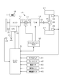
- FIG. 1 is a configuration diagram showing an outline of a vehicle control system
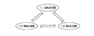
- FIG. 2 is an explanatory diagram showing an outline of each traveling state.
- FIG. 3 is a timing chart when transitioning from the inertia running state to the regenerative running state
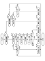
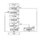
- FIG. 4 is a flowchart showing the travel control process.
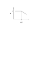
- FIG. 5 is a correlation diagram showing the relationship between the SOC and the coefficient ⁇ .
- FIG. 6 is a flowchart showing a travel control process in the second embodiment.
- FIG. 7 is a flowchart showing a regenerative energy estimation process in the third embodiment.
- FIG. 1 is a configuration diagram showing an outline of a vehicle control system
- FIG. 2 is an explanatory diagram showing an outline of each traveling state.
- FIG. 3 is a timing chart when transitioning from the inertia running state to the regenerative running state
- FIG. 4 is a flowchart showing the travel control process.
- FIG. 5 is a correlation diagram showing the relationship between the SOC and
- FIG. 8 is a correlation diagram showing the relationship between the vehicle speed, the road surface gradient, and the regeneration duration time.
- FIG. 9 is a configuration diagram showing an outline of the vehicle control system in the fourth embodiment.
- FIG. 10 is a flowchart showing a processing procedure of shift control in the fourth embodiment.
- FIG. 11 is a timing chart during inertial running in the fourth embodiment.
- FIG. 12 is a flowchart showing a processing procedure of regenerative power generation in the fifth embodiment.
- FIG. 13 is a correlation diagram illustrating the relationship among the brake operation amount, the road surface gradient, and the regeneration request output.
- an engine 11 is a multi-cylinder internal combustion engine driven by combustion of fuel such as gasoline or light oil, and appropriately includes a fuel injection valve, an ignition device, and the like as is well known.
- the engine 11 is integrally provided with an ISG 13 as a generator and an electric motor.
- a rotating shaft 14 of the ISG 13 is drivingly connected to the engine output shaft 12 by a belt or the like. In this case, the rotation shaft 14 of the ISG 13 is rotated by the rotation of the engine output shaft 12, while the engine output shaft 12 is rotated by the rotation of the rotation shaft 14 of the ISG 13.
- the ISG 13 has a power generation function for generating power (regenerative power generation) by rotation of the engine output shaft 12 and a power output function for applying a rotational force to the engine output shaft 12.
- a power generation function for generating power (regenerative power generation) by rotation of the engine output shaft 12
- a power output function for applying a rotational force to the engine output shaft 12.
- An in-vehicle battery 15 as a storage battery is electrically connected to the ISG 13.
- the power is supplied from the battery 15 to drive the ISG 13 and the battery 15 is charged by the generated power of the ISG 13.
- the electric power of the battery 15 is used to drive various electric loads mounted on the vehicle.
- an auxiliary device 16 such as a water pump or a fuel pump is mounted on the vehicle 10 as a driven device that is driven by the rotation of the engine output shaft 12.
- an air conditioner compressor may be included as the driven device.
- Driven devices include those directly coupled to the engine output shaft 12 and those coupled to the engine output shaft 12 by the clutch means in addition to those coupled to the engine 11 by a belt or the like. .
- a transmission 18 is connected to the engine output shaft 12 via a clutch device 17 having a power transmission function.
- the clutch device 17 is, for example, a friction clutch, and includes a disk (flywheel or the like) on the engine 11 side connected to the engine output shaft 12 and a disk (clutch disk) on the transmission 18 side connected to the transmission input shaft 21. Etc.) and a set of clutch mechanisms. When both disks come into contact with each other in the clutch device 17, the power is transmitted between the engine 11 and the transmission 18 (clutch connection state), and both the disks are separated from each other. Then, a power cut-off state (clutch cut-off state) is established in which power transmission between the engine 11 and the transmission 18 is cut off.
- the clutch device 17 of the present embodiment is configured as an automatic clutch that performs switching between a clutch engagement state / clutch disengagement state by an actuator such as a motor.
- the clutch device 17 may be provided inside the transmission 18.
- the transmission 18 is, for example, a continuously variable transmission (CVT) or a multi-stage transmission having a plurality of shift stages.
- the transmission 18 shifts the motive power of the engine 11 input from the transmission input shaft 21 at a gear ratio according to the vehicle speed V and the engine rotation speed, and outputs it to the transmission output shaft 22.
- Wheels 27 are connected to the transmission output shaft 22 via a differential gear 25 and a drive shaft 26 (vehicle drive shaft).
- Each wheel 27 is provided with a brake device 28 that applies a braking force to each wheel 27 by being driven by a hydraulic circuit (not shown) or the like.
- the brake device 28 adjusts the braking force for each wheel 27 in accordance with the pressure of a master cylinder (not shown) that transmits the depression force of the brake pedal to the hydraulic oil.
- the present system includes an engine ECU 31 that controls the operating state of the engine 11 and a transmission ECU 32 that controls the clutch device 17 and the transmission 18 as on-vehicle control means.
- Each of these ECUs 31 and 32 is a well-known electronic control device including a microcomputer or the like, and controls the engine 11, the transmission 18 and the like based on detection results of various sensors provided in this system. Are implemented as appropriate.
- the ECUs 31 and 32 are communicably connected to each other, and can share control signals, data signals, and the like.
- the ECU 31 includes two ECUs 31 and 32, and the engine ECU 31 constitutes a “vehicle control device”.
- the present invention is not limited to this, and two or more ECUs constitute a vehicle control device. May be.
- an accelerator sensor 41 that detects an operation amount (accelerator operation amount) of an accelerator pedal as an accelerator operation member
- a brake sensor 42 that detects an operation amount (brake operation amount) of a brake pedal as a brake operation member.
- a vehicle speed sensor 43 for detecting the vehicle speed V
- an inclination angle sensor 44 for detecting the inclination angle of the road surface of the vehicle 10
- a rotation speed sensor 45 for detecting the engine rotation speed
- a battery sensor 46 for detecting the state of the battery 15, and the like.
- the detection signals of these sensors are sequentially input to the engine ECU 31.
- the system is provided with a load sensor (air flow meter, intake pressure sensor) for detecting engine load, a cooling water temperature sensor, an outside air temperature sensor, an atmospheric pressure sensor, and the like, which are not shown.
- the engine ECU 31 performs various engine controls such as fuel injection amount control by a fuel injection valve and ignition control by an ignition device based on detection results of various sensors, engine start by ISG 13, engine torque assist and power generation control, brake device Brake control by 28 is performed. Further, the transmission ECU 32 performs intermittent control of the clutch device 17 and shift control of the transmission 18 based on detection results of various sensors.
- the vehicle 10 has a function of performing inertial running while the clutch device 17 is in a disconnected state under the situation where the vehicle 10 is running by driving the engine 11. Moreover, it has the function to perform the regenerative driving
- FIG. 2 is an explanatory diagram showing an outline of each traveling state of the vehicle 10.
- the normal running state is a state in which the vehicle 10 is caused to travel with the engine 11 in an operating state and the clutch device 17 in a connected state (specifically, a state corresponding to a shift operation position by a driver).
- the inertia traveling state is a state in which the vehicle 10 is coasted with the engine 11 stopped and the clutch device 17 disconnected.
- the regenerative travel state is a state in which the engine 11 is in an operating state (no fuel injection), the clutch device 17 is in a connected state, regenerative power generation is performed by the ISG 13, and the vehicle 10 travels.
- (1) the transition from the normal traveling state to (2) the inertial traveling state and (2) the transition from the inertial traveling state to (1) the normal traveling state are each performed according to the establishment of known conditions.
- the engine ECU 31 shifts the vehicle 10 to (2) the inertial traveling state in accordance with establishment of predetermined coasting conditions including the accelerator condition and the brake condition.
- the predetermined coasting conditions include that the engine rotational speed is stable at a predetermined value or higher (for example, idle rotational speed or higher), the vehicle speed V is within a predetermined range (for example, 20 to 120 km / h), road surface It may be included that the gradient (tilt) is within a predetermined range.
- the engine ECU 31 shifts the vehicle 10 to (1) the normal traveling state in accordance with establishment of predetermined coast release conditions including the accelerator condition and the brake condition. .
- the inertial running state may be canceled as the predetermined coast implementation condition is not established.
- (1) transition from the normal travel state to (3) regenerative travel state, and (3) transition from the regenerative travel state to (1) normal travel state are each performed according to the establishment of a known condition.
- the engine ECU 31 (3) in the regenerative running state according to the establishment of predetermined regeneration execution conditions including the brake condition and the storage state of the battery 15.
- regenerative power generation is performed by the ISG 13, and kinetic energy is stored in the battery 15 as electric energy.
- the engine ECU 31 shifts to (1) the normal travel state in accordance with the establishment of a predetermined regenerative release condition including the accelerator condition.
- (2) the transition from the inertia traveling state to (3) the regenerative traveling state and (3) the transition from the regenerative traveling state to (2) the inertia traveling state can be performed.
- the energy (energy consumption) consumed for increasing the engine rotation speed may be larger than the energy recovered by the regenerative travel (regenerative energy). In such a case, it is not preferable from the viewpoint of improving fuel consumption.
- the relationship between energy consumption and regenerative energy will be described with reference to FIG.
- a predetermined brake operation is performed during coasting based on a known coast release condition (for example, when the amount of braking operation is greater than a predetermined threshold Th)
- the brake operation is included in the predetermined regeneration execution condition during inertial running.
- the brake operation here may be a brake operation by a driver or a deceleration control (automatic brake or the like) by a vehicle operation control unit.
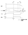
- the vehicle 10 is in the coasting state before the timing t12 and at the timings t13 to t14, is in the regenerative traveling state at the timings t12 to t13 and the timings t15 to t16, and is in the normal traveling state after the timing t16. .
- the energy consumed when shifting to the regenerative traveling at timing t12 to t13 is A1
- the energy recovered by the regenerative traveling at timing t12 to t13 is B1
- shifting to the regenerative traveling at timing t15 to t16 is A2
- the energy recovered by regenerative travel at timings t15 to t16 is B2.
- the regenerative energy B2 is larger than the consumed energy A2, and the fuel efficiency effect by the regenerative travel is obtained.
- the consumed energy A1 is larger than the regenerative energy B1, and the consumed energy cannot be recovered by the regenerative energy. That is, in the regenerative travel at the timing t12 to t13, energy is lost by shifting from the inertia travel to the regenerative travel, which is considered disadvantageous from the viewpoint of energy efficiency.
- the transition from the inertia travel to the regenerative travel is performed. Specifically, when it is determined that the regenerative energy is larger than the consumed energy, the inertial traveling is canceled and the regenerative traveling is performed, and when it is determined that the regenerative energy is smaller than the consumed energy, the inertial traveling is maintained. . That is, the transition from the inertia traveling to the regenerative traveling is enabled, and the transition to the disadvantageous regenerative traveling from the viewpoint of energy efficiency is suppressed.
- the engine ECU 31 estimates the consumed energy A1 and the regenerative energy B1. If it is determined that the consumed energy A1 is larger than the regenerative energy B1, the inertia traveling is maintained without shifting from the inertia traveling to the regeneration traveling. In other words, in this case, the clutch is kept off (disengaged) at timings t12 to t13, and neither energy consumption A1 nor regenerative energy B1 is generated.
- the regenerative travel at the timings t12 to t13 which is disadvantageous from the viewpoint of energy efficiency, is not performed in FIG. 3, but the regenerative travel at the advantageous timings t15 to t16 is performed.
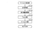
- the engine ECU 31 estimates the energy consumption Erec and the regenerative energy Eregen, respectively, when a brake operation is performed during inertial running.
- the energy consumption Erec refers to the energy required to rotate the engine output shaft 12 by the ISG 13. Specifically, the energy consumption Erec is estimated based on the sum of the required rotational energy calculated from the vehicle speed V and the loss energy including friction loss. More specifically, it is estimated based on the following formula (1).
- j represents the inertia (moment of inertia) of the engine 11
- ⁇ t represents the target rotational speed of the engine 11
- ⁇ 0 represents the current engine rotational speed
- Ploss represents the loss output
- Tst represents the return target time
- Effmot represents the output efficiency in the power running drive of the ISG 13
- Effbatt_out represents the output efficiency of the battery 15.
- the loss output is engine friction or the like and can be calculated by a known method.
- ⁇ t is calculated based on the vehicle speed V. In this case, ⁇ t is calculated as a larger value as the vehicle speed V increases.
- ⁇ 0 is considered to be zero in many cases. Further, it is considered that other parameters do not fluctuate greatly in each coasting. Then, it is considered that the energy consumption Erec greatly depends on the vehicle speed V.
- regenerative energy Eregen refers to energy that can be recovered by regenerative travel.
- the regenerative energy Eregen is estimated using a regenerative output Pregen calculated based on the brake operation amount and a regenerative duration Tgen that is predicted to continue regenerative travel. More specifically, it is estimated based on the following formula (2).
- Effgen represents the output efficiency in the power generation of the ISG 13, and Effbatt_in represents the input efficiency of the battery 15.
- the regeneration continuation time Tgen is a predetermined value determined in advance by adaptation or the like, and is, for example, 10 seconds.
- the engine ECU 31 controls the transition from inertial running to regenerative running by comparing the estimated energy consumption Erec and regenerative energy Eregen, respectively.
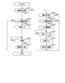
- step S11 it is determined whether or not the vehicle 10 is currently in an inertia running state with the clutch off. If YES, the process proceeds to step S12, and if NO, the process proceeds to step S21.
- step S12 it is determined whether or not the brake is on. Whether or not the brake is on is determined based on, for example, that the amount of brake operation detected by the brake sensor 42 is greater than zero. If step S12 is YES, the process proceeds to step S13.
- step S13 energy consumption Erec is estimated.
- the consumed energy Erec is estimated based on the above-described equation (1), for example.
- step S14 the regenerative energy Eregen is estimated.
- the regenerative energy Eregen is estimated based on the above-described equation (2), for example.
- step S15 it is determined whether or not the estimated regenerative energy Eregen is larger than the consumed energy Erec.
- step S15 is YES, that is, when the regenerative energy Eregen is larger than the consumed energy Erec, the inertia traveling is canceled and the transition to the regenerative traveling is performed (step S16). If step S15 is NO, that is, if the consumed energy Erec is larger than the regenerative energy Eregen, coasting is maintained (step S17).
- step S12 when step S12 is NO, it progresses to step S18 and it is determined whether it is in the accelerator-on state. Whether or not the accelerator is on is determined based on, for example, that the accelerator operation amount detected by the accelerator sensor 41 is greater than zero. If step S18 is YES, the inertia traveling is canceled and the transition to the normal traveling is performed (step S19). If step S18 is NO, this process is ended as it is. That is, the vehicle 10 maintains the coasting state.
- step S21 it is determined whether or not the vehicle 10 is currently in a regenerative running state. If YES, the process proceeds to step S22. If NO, the process is terminated. In step S22, it is determined whether or not the accelerator is on. When step S22 is YES, that is, when the accelerator is turned on during the regenerative travel, the regenerative travel is canceled and the shift to the normal travel is performed (step S23).
- step S22 when step S22 is NO, it progresses to step S24, and it is determined whether it is in a brake-off state.
- the brake-off state is determined based on, for example, that the brake operation amount detected by the brake sensor 42 is zero.
- step S24 in addition to the brake off state, for example, the SOC of the battery 15 is equal to or higher than a predetermined value (for example, a value close to full charge), or the vehicle speed V is equal to or lower than a predetermined value (for example, 30 km / h). The following may be determined. If step S24 is YES, a transition from regenerative travel to inertial travel is performed (step S25). If step S24 is NO, this process is ended as it is. That is, the vehicle 10 maintains the regenerative travel state.
- a predetermined value for example, a value close to full charge
- a predetermined value for example, 30 km / h
- Steps S13 and S14 correspond to an “estimator”
- step S15 corresponds to a “determination unit”
- steps S16 and S17 correspond to a “travel controller”.
- the energy consumption Erec consumed by adjusting the engine speed is estimated, and the regenerative energy Eregen recovered by the regenerative traveling is estimated. To do. Then, based on the comparison between the consumed energy Erec and the regenerative energy Eregen, the transition from the inertia traveling to the regenerative traveling is performed. Specifically, when it is determined that the regenerative energy Eregen is larger than the consumed energy Erec, the transition from the inertia traveling to the regenerative traveling is performed. Therefore, the energy exceeding the consumed energy Erec can be recovered by the regenerative traveling.
- coasting is maintained when it is determined that the regenerative energy Eregen is smaller than the energy consumption Erec, so that the fuel efficiency effect by coasting can be obtained, and the shift to unfavorable regeneration from the viewpoint of energy efficiency can be achieved. Can be suppressed. Furthermore, the frequency of switching from coasting to regenerative driving can be suppressed, leading to improved drivability. Thereby, inertial running and regenerative running can be switched appropriately.
- the consumed energy Erec is energy required for rotating the engine output shaft 12 to the target engine speed, and is considered to correlate with the vehicle speed V. That is, when the vehicle speed V is high, the target engine speed increases, and the energy consumption Erec increases accordingly. In consideration of this point, the energy consumption Erec is estimated based on the vehicle speed V, so that the energy consumption Erec can be estimated with high accuracy. As a result, it is possible to appropriately determine the transition from inertial travel to regenerative travel.
- Regenerative energy Eregen is considered to correlate with the amount of brake operation. For example, when the brake operation amount is large, the driver's request for deceleration is large, and the regenerative energy Eregen is also large. Considering this point, the regenerative energy Eregen is estimated based on the brake operation amount, so that the regenerative energy Eregen can be estimated with high accuracy. As a result, it is possible to appropriately determine the transition from inertial travel to regenerative travel.
- the engine 11 is stopped during inertial running, but this may be changed.
- the engine rotation speed may be maintained at an idle rotation speed (for example, 700 rpm) without stopping the engine 11 during inertial traveling.
- the range in which the engine rotation speed is increased by driving the ISG 13 is smaller than the configuration in which the engine 11 is stopped. Therefore, energy consumption Erec when shifting from inertial traveling to regenerative traveling is reduced.
- the engine rotation speed is maintained at the idle rotation speed, the responsiveness at the time of releasing the inertial running is improved as compared with the case where the engine 11 is stopped.
- the engine rotation speed may be adjusted by means other than driving the ISG 13.
- the engine rotation speed is adjusted by the operation (combustion) of the engine 11.
- the energy required for operating the engine 11 may be estimated as the consumed energy Erec.
- the engine rotation speed is increased by combining the driving of the ISG 13 and the combustion of the engine 11 may be employed.
- the combustion efficiency of the engine 11 is poor in the low rotation speed region, so that the driving by the ISG 13 is considered to be more efficient than the combustion of the engine 11.
- the combustion efficiency of the engine 11 is good. Considering this point, it is preferable to select driving of the ISG 13 and combustion of the engine 11 according to the engine rotation speed.
- the engine rotational speed is increased by driving the ISG 13, and in a high rotational speed range where the engine rotational speed is equal to or higher than the predetermined value K, combustion of the engine 11 occurs. It is good to increase the engine speed.
- the predetermined value K is, for example, an idle rotation speed. In this case, for example, if the energy consumption Erec is estimated as energy consumed by driving the ISG 13, the energy consumption Erec when shifting from inertia traveling to regenerative traveling is reduced.
- the engine rotation speed may be increased by a combination of a starter (not shown) and the combustion of the engine 11 instead of the combination of the drive of the ISG 13 and the combustion of the engine 11.
- the ISG 13 is used as the regeneration device, but the regeneration device is not limited to this.
- an alternator having only a power generation function may be used as the regeneration device, and a flywheel may be used as the regeneration device.
- the kinetic energy of the vehicle 10 is stored as rotational energy in the flywheel.
- a starter may be used as a device for starting the engine 11.
- the SOC is acquired as a parameter indicating the storage state of the battery 15, and the regenerative energy Eregen estimated based on the SOC is corrected.
- the recovery of regenerative energy Eregen is limited depending on the SOC of the battery 15. For example, when the SOC of the battery 15 is close to full charge, the power that can be charged to the battery 15 is small, and even if regenerative power generation is performed, the regenerative energy Eregen that is recovered may be limited. is there.
- the engine ECU 31 acquires the SOC of the battery 15 and corrects the regenerative energy Eregen estimated based on the SOC. Then, the regenerated energy Eregen after correction is used to compare with the consumed energy Erec.
- the correction for example, when the SOC of the battery 15 is close to full charge, the electric energy that can be charged in the battery 15 becomes small, so that the estimated regenerative energy Eregen is corrected to be reduced.
- the correction method is not particularly limited, for example, there is a method of multiplying the estimated regenerative energy Eregen by a coefficient ⁇ .
- the SOC within the usage range of the battery 15 and the coefficient ⁇ have a correlation as shown in FIG. 5, for example.
- the coefficient ⁇ is 1 when the SOC is equal to or less than the predetermined value P.
- the regenerative energy Eregen does not change before and after the correction.
- the coefficient ⁇ decreases as the SOC increases.
- FIG. 6 is a flowchart showing a processing procedure of the travel control process in the second embodiment, and this process is repeatedly performed by the engine ECU 31 at a predetermined period in place of FIG. 4 described above.
- the same processes as those in FIG. 4 are the addition of steps S31 and S32 and the change of the processing content of step S15.
- step S13 when the vehicle 10 is coasting and the brake is on (when both steps S11 and S12 are YES), the consumed energy Erec is estimated (step S13), and the regenerative energy Eregen is estimated. Is estimated (step S14).
- step S31 the engine ECU 31 acquires the SOC of the battery 15.
- step S32 the regenerative energy Eregen is corrected based on the acquired SOC. Specifically, the regenerative energy Eregen is corrected based on the above-described correlation between the SOC and the coefficient ⁇ .
- step S15 it is determined whether the corrected regenerative energy Eregen is larger than the consumed energy Erec. If step S15 is YES, it will progress to step S16 and will transfer to regeneration driving
- the state on the side where the regenerative energy Eregen is stored can be considered.
- the transition to the regenerative travel that is disadvantageous from the viewpoint of energy efficiency can be suitably suppressed.
- the regenerative energy Eregen is corrected based on the SOC of the battery 15.
- the regenerative energy Eregen may be corrected based on other parameters indicating the state of the battery 15.
- the regenerative energy Eregen may be corrected based on the temperature of the battery 15.
- the regenerative energy Eregen may be corrected based on a parameter indicating the state of the ISG 13. That is, in this case, the regenerative energy Eregen is corrected in consideration of the state on the energy recovery side. For example, in the configuration in which the regenerative energy Eregen is corrected based on the temperature of the ISG 13, the temperature of the ISG 13 (for example, the temperature of the switching element of the inverter unit or the temperature of the stator of the motor unit) is acquired in step S31 in FIG. In step S32, the regenerative energy Eregen is corrected based on the temperature.
- the method of multiplying the coefficient ⁇ is used as a method for correcting the regenerative energy Eregen, but the present invention is not limited to this.
- the battery acceptable energy is calculated based on the SOC of the battery 15 and the battery capacity, and a smaller value of the calculated battery acceptable energy and the estimated regenerative energy Eregen is used as the corrected regenerative energy Eregen. Good.
- the regenerative energy Eregen is corrected based on the SOC.
- the SOC is a predetermined value or more
- the transition from inertial running to regenerative running may be prohibited.
- the predetermined value is set to, for example, an SOC close to full charge.
- a transition from inertia traveling to regenerative traveling may be prohibited.
- the transition to the regenerative traveling is prohibited and the inertia traveling is maintained. You may make it do.
- the past duration is acquired according to the traveling condition of the vehicle 10, and the current duration (regeneration is based on the duration).
- the duration Tgen
- the regeneration energy Eregen is estimated using the set regeneration duration Tgen.
- the engine ECU 31 stores the duration of regenerative travel as a history in a memory or the like in the engine ECU 31 for each travel condition in each regenerative travel in the past.
- the traveling conditions include, for example, vehicle speed V, road surface gradient, and the like. In this case, it is considered that the longer the vehicle speed V is, the longer the duration of regenerative travel is. In addition, it is considered that the longer the road gradient, the longer the duration of regenerative travel.
- FIG. 7 describes the processing procedure for estimating the regenerative energy Eregen in step S14 of FIG. This process is performed by the engine ECU 31 as a subroutine process when step S14 of FIG. 4 is performed. That is, in FIG. 4, when the vehicle 10 is in an inertia running state and the brake is on (when both steps S11 and S12 are YES), the consumed energy Erec is estimated (step S13). Then, the process proceeds to step S101 in FIG.
- step S101 the traveling condition of the vehicle 10 is acquired.
- the vehicle speed V is acquired based on the detection value by the vehicle speed sensor 43
- the road surface gradient is acquired based on the detection value by the inclination angle sensor 44.
- step S102 the duration of past regenerative travel is acquired according to the acquired travel conditions. For example, the duration of regenerative travel that has been performed in the past at a vehicle speed V that is approximately the same as the current vehicle speed V is acquired. In addition, you may consider a road surface gradient.
- the current regeneration duration Tgen is set based on the obtained duration.
- the average value of the duration of regenerative travel for the past 10 times under the same travel conditions is set as the regeneration duration Tgen.
- step S104 the regenerative energy Eregen is estimated based on the set regeneration continuation time Tgen, and the process returns to step S15 in FIG.
- step S103 corresponds to a “setting unit”
- step S104 corresponds to an “estimating unit”.
- Regenerative energy Eregen is considered to correlate with the duration of regenerative travel.
- the regeneration duration Tgen is set as the current duration, and based on the set regeneration duration Tgen and the brake operation amount. Therefore, the regenerative energy Eregen can be estimated with high accuracy.
- the duration time is stored each time, and the regeneration duration time Tgen is set based on the stored history of the continuous time. Therefore, according to the tendency of the regenerative travel for each vehicle 10.
- the regeneration duration Tgen can be set appropriately.
- the history of the past duration is acquired according to the driving conditions of the vehicle 10 and the regeneration duration Tgen is set based on the history, the conditions affecting the duration of the regeneration running are taken into account.
- the regeneration duration Tgen can be set.
- the regeneration continuation time Tgen can be appropriately set according to the operating conditions at each time, and as a result, the regenerative energy Eregen can be estimated with high accuracy.
- the regeneration duration Tgen is set based on the past regeneration travel duration stored in a memory or the like. However, this may be changed.
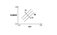
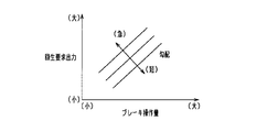
- the regeneration duration Tgen may be set each time based on the traveling conditions of the vehicle 10. In such a configuration, for example, a correlation map as shown in FIG. 8 can be used. In FIG. 8, the regeneration duration Tgen is longer as the vehicle speed V is higher, and the regeneration duration Tgen is longer as the road gradient is steeper.
- the regeneration duration time Tgen may be set using traffic information such as traffic lights and traffic congestion on the road. In this case, for example, if the traffic light that exists in the traveling direction of the vehicle 10 is a red signal, the vehicle 10 needs to stop, so the regeneration duration Tgen is set short.
- FIG. 9 schematic structure of the vehicle control system in 4th Embodiment is shown.
- the fourth embodiment is directed to a vehicle control system including a transmission 51 between the engine output shaft 12 and the rotating shaft 14 of the ISG 13.
- the transmission 51 can change the speed ratio of the rotational power by the ISG 13 (the rotational speed of the rotary shaft 14 / the rotational speed of the engine output shaft 12).
- the gear ratio is N2 / N1.
- the engine ECU 31 controls the gear ratio of the transmission 51 according to the state of the vehicle 10. Except that this transmission 51 is provided, it is the same as the configuration diagram of FIG.
- the control when shifting from (2) the inertia running state to (3) the regenerative running state is shown in FIG. 2, but in the fourth embodiment, (2) in the inertia running state, in particular.
- the control will be described.
- the gear ratio of the transmission 51 in inertial running, is changed to a side that suppresses the decrease in engine rotation speed. Specifically, when the vehicle 10 is in a normal running state and a predetermined coasting condition is satisfied, the gear ratio (the rotational speed of the rotary shaft 14 / the rotational speed of the engine output shaft 12) is set to be higher than the previous gear ratio. Enlarge. Then, the vehicle 10 is switched to coasting with the gear ratio increased, and coasting is performed. Then, the gear ratio is reduced when shifting from inertia traveling to normal traveling. That is, the increased gear ratio is restored.
- the gear ratio before shifting to inertial running by increasing the gear ratio before shifting to inertial running, the kinetic energy at the time of deceleration can be recovered as rotational energy by the ISG 13, and after recovering, it is possible to shift to inertial driving.
- the inertia of the engine 11 during inertial traveling is increased, a decrease in engine rotation speed during inertial traveling is suppressed, and the period during which the engine output shaft 12 rotates during inertial traveling can be extended.
- the rotation of the engine output shaft 12 is ensured to reduce the energy consumption Erec associated with the transition.
- the transition between the normal traveling and the inertia traveling is shown, but the same applies to the transition between the regenerative traveling and the inertia traveling.
- step S41 it is determined whether or not the vehicle 10 is currently in the non-inertial traveling state (normal traveling state or regenerative traveling state). If step S41 is YES, the process proceeds to step S42, and if step S41 is NO, the process proceeds to step S46. In step S42, it is determined whether or not the coast execution condition is satisfied. For example, regarding the transition from normal travel to inertial travel, it is determined that the accelerator is off and the brake is off. If step S42 is YES, it will progress to step S43, and if step S42 is NO, this process will be complete
- step S43 the gear ratio of the transmission 51 is increased. Specifically, the gear ratio is changed so that the rotation speed of the rotation shaft 14 of the ISG 13 is larger than the rotation speed of the engine output shaft 12.
- step S44 it is determined whether or not a predetermined time T has elapsed since the gear ratio of the transmission 51 was changed. While this predetermined time T elapses, the kinetic energy is recovered as rotational energy by the ISG 13. Then, when the predetermined time T has elapsed (S44: YES), the process proceeds to step S45, where the clutch is turned off (disengaged) and the vehicle shifts to coasting.
- step S47 it is determined whether a coast release condition is satisfied. For example, regarding the transition to normal travel, it is determined whether or not the accelerator is turned on. Regarding the transition to regenerative travel, it is determined whether the brake is turned on and the regenerative energy Eregen is greater than the consumed energy Erec. If step S47 is YES, it will progress to step S48 and will start drive of ISG13.
- step S49 it is determined whether or not it is a transition timing to normal driving or regenerative driving. Specifically, the engine ECU 31 determines whether or not the engine rotational speed has increased to a rotational speed corresponding to the vehicle speed V by driving the ISG 13. If it is determined that it is the transition timing (step S49: YES), the process proceeds to step S50. In step S50, the transmission ratio of the transmission 51 is reduced. That is, the gear ratio is returned to the state before the coast execution condition is established. In step S51, inertial running is canceled and the routine proceeds to normal running or regenerative running. On the other hand, if step S46 and step S47 are NO, this process will be complete
- FIG. 11 shows a timing chart showing the processing of FIG. 10 more specifically.
- reference control control that does not change the transmission ratio of the transmission 51
- control in this embodiment control that changes the transmission ratio of the transmission 51
- the control in this embodiment is indicated by a solid line.
- FIG. 11 shows a scene in which the vehicle 10 shifts from the normal driving state to the inertial driving state and then shifts from the inertial driving state to the regenerative driving state.
- the transmission gear ratio of the transmission 51 is changed from LOW to HIGH at the timing t21 when the coast execution condition is satisfied. That is, in this case, the gear ratio is made larger than the gear ratio in the reference control. Then, the kinetic energy is recovered, and at a timing t22 after a predetermined time T has elapsed, the clutch is turned off and switched to inertial running. That is, in this case, the predetermined time T is a delay time from the establishment of the coast execution condition until the coasting is actually started. Thereafter, the engine rotation speed decreases, but the decrease speed becomes slower than that in the reference control.
- the range of increase in the engine rotation speed by driving the ISG 13 is smaller than that in the reference control ( ⁇ NE2 ⁇ NE1). That is, by increasing the gear ratio in inertia traveling, it is possible to reduce the energy consumption Erec when shifting from inertia traveling to non-inert inertia traveling.
- the gear ratio was changed to the side that suppresses the decrease in engine speed during inertial running. Specifically, the gear ratio is changed from LOW to HIGH when the coast execution condition is satisfied, and coasting is performed in the state of HIGH. In this case, by setting the gear ratio to HIGH, it is possible to suppress a decrease in the engine rotation speed as compared with a case where coasting is performed with LOW. Thereby, the period during which the engine output shaft 12 rotates can be extended, and as a result, it is possible to reduce the energy consumption Erec when shifting from inertia traveling to non-inert inertia traveling.
- the ISG 13 When traveling by the combustion of the engine 11, the ISG 13 is rotated, and a sliding loss occurs with the rotation. Considering this point, when the inertia traveling is canceled, that is, when the transition from the inertia traveling to the non-inert inertia traveling (normal traveling and regenerative traveling) is performed, the gear ratio is changed from HIGH to LOW. In this case, the rotational speed of the ISG 13 with respect to the engine rotational speed in non-inertial travel is smaller than that during inertial travel. Thereby, the sliding loss accompanying the rotation of the ISG 13 can be reduced in the non-inertial traveling, and accordingly the traveling by the combustion of the engine 11 can be suitably performed. Further, in the configuration in which the cooling fan is drivingly connected to the rotating shaft 14 of the ISG 13, the rotation speed of the ISG 13 is reduced, so that the rotation sound of the cooling fan can be reduced.
- the gear ratio is reduced when releasing the inertia running (the state before the coast execution condition is satisfied), but the timing for reducing the gear ratio is not limited to this.
- the gear ratio may be reduced when the engine rotation speed reaches a predetermined threshold value NEth during a period in which the engine rotation speed is increased by driving the ISG 13 at the time of transition from inertial running to regenerative running.
- a step of determining whether or not the engine speed is equal to or higher than the threshold NEth is provided as a step that proceeds when step S49 of FIG. 10 is NO. If the engine speed is equal to or higher than the threshold value NEth, the process proceeds to step S50, and the gear ratio is reduced. That is, the gear ratio is reduced before the inertia running is released. On the other hand, if the engine speed is less than the threshold value NEth, the present process is terminated as it is.
- the threshold value NEth is set to a value larger than the engine rotation speed range where a large torque (passing torque) at the time of starting the engine is required.
- the sliding loss of the ISG 13 can be reduced before the inertia traveling is canceled by reducing the gear ratio at a timing when a large torque is not required at the time of starting the engine. It is possible to reduce the energy consumption Erec associated with the transition to.
- the transmission 51 is provided between the engine output shaft 12 and the rotating shaft 14 of the ISG 13.
- the present invention is limited to this as long as the gear ratio of the rotational power by the ISG 13 is variable. Not. For example, it is good also as a structure which provides a speed change function to ISG13 and changes a gear ratio by ISG13.
- an alternator having only a power generation function or a rotating machine (flywheel or the like) having no power generation function may be used instead of the ISG 13, for example.
- a transmission is provided between the engine output shaft 12 and a rotation shaft such as an alternator, and the gear ratio of the transmission is changed to a side that suppresses a decrease in engine rotation speed during inertial running.
- the engine ECU 31 When performing regenerative power generation, the engine ECU 31 transmits a power generation command to the ISG 13. At this time, the engine ECU 31 sets the regeneration request output based on the brake operation amount, the storage state of the battery 15, and the like. Then, based on the regeneration request output, the ISG 13 is caused to perform regenerative power generation. Thereby, the electric power according to the state of the vehicle 10 is obtained by regenerative power generation.
- an output limit may be provided for the regenerative power generation of the ISG 13. Therefore, even when the regenerative request output is large, regenerative power generation may be suppressed to a predetermined output value Wth or less due to the output limitation, and in this case, recovery of the regenerative energy Eregen is limited.
- the output limit of regenerative power generation is set in consideration of the duration of regenerative travel, and is set assuming regenerative travel of about 30 seconds, for example.
- the engine ECU 31 sets the regeneration duration Tgen and the regeneration request output when the regeneration execution condition is satisfied. And if regeneration continuation time Tgen is below predetermined threshold TA and regeneration required output is above predetermined threshold WA, regenerative power generation with an output larger than output value Wth is permitted.
- the threshold value TA is a determination value for determining regenerative travel for an extremely short time, and is set to 3 seconds, for example.
- the threshold value WA is set to a value corresponding to the output limit of regenerative power generation. That is, in this case, regenerative power generation with a large output (output exceeding the output limit of regenerative power generation) is performed in an extremely short time. Thereby, the regenerative energy Eregen can be efficiently recovered.
- step S61 it is determined whether or not the vehicle 10 is currently in a non-regenerative traveling state (normal traveling state or inertial traveling state). If step S61 is YES, the process proceeds to step S62. If step S61 is NO, the process is terminated. In step S62, it is determined whether or not a regeneration execution condition is satisfied. For example, regarding the transition from inertial running to regenerative running, it is determined whether the brake is turned on and the regenerative energy Eregen is greater than the consumed energy Erec. If step S62 is YES, the process proceeds to step S63, and if step S62 is NO, the process ends.
- a regeneration execution condition For example, regarding the transition from inertial running to regenerative running, it is determined whether the brake is turned on and the regenerative energy Eregen is greater than the consumed energy Erec.
- step S63 the regeneration duration Tgen is set.
- the regeneration continuation time Tgen is set in the same manner as the process of step S103 in FIG.
- a regeneration request output is set.
- the regeneration request output is set by applying the brake operation amount and the road surface gradient to the map shown in FIG. In the map of FIG. 13, the regeneration request output increases as the brake operation amount increases, and the regeneration request output increases as the road surface gradient increases.
- the road surface gradient is acquired by the inclination angle sensor 44, GPS information, a gyro sensor (not shown), or the like. Steps S63 and S64 correspond to a “setting unit”.
- step S65 it is determined whether or not the regeneration continuation time Tgen is equal to or less than the threshold value TA and the regeneration request output is equal to or greater than the threshold value WA. If step S65 is NO, it will progress to step S66 and will implement regenerative power generation below the output value Wth. That is, in this case, regenerative power generation is performed within the range of the normal output limit. On the other hand, if step S65 is YES, the process proceeds to step S67, and regenerative power generation with an output larger than the output value Wth is permitted. Specifically, the engine ECU 31 transmits a power generation command to the ISG 13 to generate power with an output larger than Wth, and regenerative power generation is performed. Step S67 corresponds to a “permission unit”.
- excitation of the rotor of the motor unit of the ISG 13 is started based on a power generation command from the engine ECU 31, and regenerative power generation is performed after the excitation is completed. That is, it takes time to complete the excitation of the rotor, and when regenerative power generation is performed in an extremely short time, the time required for this excitation greatly affects the power generation efficiency.
- the engine ECU 31 may cause the ISG 13 to start a preparatory operation for regenerative power generation before the regenerative execution condition is satisfied. Specifically, when the amount of brake operation becomes equal to or greater than the threshold value Th1, the engine ECU 31 causes the ISG 13 to start exciting the rotor.
- the regeneration operation condition is set such that the brake operation amount is equal to or greater than the threshold Th2, and the magnitude relationship between the threshold Th1 and the threshold Th2 is Th1 ⁇ Th2.
- the brake operation is performed in the non-regenerative running state, and when the brake operation amount becomes equal to or greater than the threshold value Th1, the excitation of the rotor is first started, and when the brake operation amount becomes equal to or greater than the threshold value Th2, regenerative power generation is performed.
- the excitation of the rotor is started before the power generation command by the engine ECU 31 so that the regenerative power generation is performed quickly, and the regenerative energy Eregen can be efficiently obtained even in an extremely short time regenerative power generation. It can be recovered.
- the ISG 13 in which the generator and the motor are integrated as the regenerative device is provided, but an alternator (generator) as the regenerative device and an electric motor that applies a rotational force to the engine output shaft 12 are provided. It is good also as a structure.
Abstract
This vehicle control apparatus is applied to a vehicle (10) provided with an engine (11), a clutch device (17) that is provided to a power transmission path connected to an output shaft (12) of the engine, and a regeneration device (13) that recovers kinetic energy of the vehicle via the output shaft. The vehicle control apparatus is provided with: a travel control unit that executes inertial traveling of the vehicle by cutting off the clutch device in accordance with establishment of an inertial traveling execution condition, and executes transition from the inertial traveling to regeneration traveling using the regeneration device by executing adjustment of the engine rotation speed and connection of the clutch device in accordance with establishment of a regeneration execution condition during the inertial traveling; and an estimation unit that, when a braking operation is performed as the regeneration execution condition during the inertial traveling, estimates consumed energy used by the adjustment of the engine rotation speed, and estimates regeneration energy recovered by the regeneration traveling. The travel control unit executes the transition from inertial traveling to regeneration traveling on the basis of a comparison between the consumed energy and the regeneration energy.
Description
本出願は、2017年3月15日に出願された日本出願番号2017-049745号に基づくもので、ここにその記載内容を援用する。
This application is based on Japanese Patent Application No. 2017-049745 filed on March 15, 2017, the contents of which are incorporated herein by reference.
本開示は、車両制御装置に関するものである。
This disclosure relates to a vehicle control device.
近年、燃費改善等を目的として、車両走行中のアクセルオフ時に、エンジンと変速機との間に設けたクラッチ装置を遮断状態にして車両を惰性走行状態にする技術が実用化されている(例えば、特許文献1)。この惰性走行は、車両の運動エネルギをそのまま走行に利用する技術であり、車両の走行距離を伸ばすことで燃費の向上を図ることができる。
In recent years, for the purpose of improving fuel efficiency and the like, a technology for putting a vehicle in an inertial running state by disengaging a clutch device provided between an engine and a transmission when an accelerator is off while the vehicle is running has been put into practical use (for example, Patent Document 1). This inertial traveling is a technology that uses the kinetic energy of a vehicle as it is for traveling, and it is possible to improve fuel efficiency by extending the traveling distance of the vehicle.
一方、車両の減速時における運動エネルギを回生エネルギとして回収し、車両のエネルギ効率を向上させる、いわゆる回生走行が知られている。例えば、運動エネルギを電気エネルギに変換する回生発電では、エンジン出力軸等の回転によってモータを発電機として機能させ、発電により生じた電気エネルギをバッテリに蓄える。
On the other hand, so-called regenerative travel is known in which kinetic energy at the time of deceleration of the vehicle is recovered as regenerative energy to improve the energy efficiency of the vehicle. For example, in regenerative power generation that converts kinetic energy into electrical energy, the motor functions as a generator by the rotation of an engine output shaft or the like, and the electrical energy generated by the power generation is stored in a battery.
ここで、更なる燃費向上の観点からすると、惰性走行及び回生走行の相互の切り替えを可能としつつ、各走行を適切に使い分けて走行できることが望ましいと考えられる。ところで、惰性走行から回生走行へ移行する際には、遮断状態となっているクラッチを接続させる必要がある。この場合、クラッチ接続時の振動や騒音等を軽減するため、エンジン回転速度を上昇させた状態でクラッチを接続することが望ましく、これにはエネルギの消費を伴う。そのため、回生走行の実施形態によっては、回生走行により回収されるエネルギよりも、エンジン回転速度の上昇に消費されるエネルギの方が大きくなる場合があると考えられる。かかる場合、燃費向上の観点から好ましくない。
Here, from the viewpoint of further improvement in fuel consumption, it is desirable to be able to travel appropriately using each travel while enabling mutual switching between inertial travel and regenerative travel. By the way, when shifting from inertial traveling to regenerative traveling, it is necessary to connect a clutch that is in a disconnected state. In this case, in order to reduce vibration, noise, and the like when the clutch is connected, it is desirable to connect the clutch with the engine speed increased, which involves energy consumption. Therefore, depending on the embodiment of the regenerative travel, it is considered that the energy consumed for increasing the engine rotation speed may be larger than the energy recovered by the regenerative travel. In such a case, it is not preferable from the viewpoint of improving fuel consumption.
本開示は上記事情を鑑みてなされたものであり、その主たる目的は、惰性走行と回生走行を適正に切り替えることができる車両制御装置を提供することにある。
The present disclosure has been made in view of the above circumstances, and a main purpose thereof is to provide a vehicle control device capable of appropriately switching between inertial traveling and regenerative traveling.
第1の手段では、
走行駆動源としてのエンジンと、該エンジンの出力軸に繋がる動力伝達経路に設けられるクラッチ装置と、前記出力軸を介して車両の運動エネルギを回収する回生装置と、を備える車両に適用され、
所定の惰性走行実施条件の成立に応じて、前記クラッチ装置を遮断状態にして前記車両の惰性走行を実施し、惰性走行中における所定の回生実施条件の成立に応じて、エンジン回転速度の調整と前記クラッチ装置の接続とを行って前記惰性走行から前記回生装置を利用した回生走行への移行を実施する走行制御部と、
前記惰性走行中に前記回生実施条件としてのブレーキ操作が実施された場合において、前記エンジン回転速度の調整により消費される消費エネルギを推定するとともに、前記回生走行により回収される回生エネルギを推定する推定部と、
を備え、
前記走行制御部は、前記消費エネルギと前記回生エネルギとの比較に基づいて、前記惰性走行から前記回生走行への移行を実施する。 In the first means,
Applied to a vehicle comprising an engine as a travel drive source, a clutch device provided in a power transmission path connected to the output shaft of the engine, and a regenerative device for recovering kinetic energy of the vehicle via the output shaft,
In response to the establishment of predetermined inertial running conditions, the clutch device is disengaged to perform inertial running of the vehicle, and in accordance with the establishment of predetermined regeneration execution conditions during inertial running, the engine rotation speed is adjusted. A travel control unit that performs connection to the regenerative travel using the regenerative device from the inertia travel by performing connection of the clutch device;
In the case where a braking operation is performed as the regeneration execution condition during the inertia traveling, an estimation is performed for estimating the energy consumed by adjusting the engine rotation speed and estimating the regeneration energy recovered by the regeneration traveling. And
With
The traveling control unit performs a transition from the inertia traveling to the regenerative traveling based on a comparison between the consumed energy and the regenerative energy.
惰性走行から回生走行へ移行する際にはエンジン回転速度の調整とクラッチ装置の接続とを行う必要があり、このエンジン回転速度の調整にはエネルギの消費を伴う。そのため、エネルギ効率の観点から、消費エネルギを加味して回生走行へ移行することが望ましい。
移行 When shifting from inertial running to regenerative running, it is necessary to adjust the engine speed and connect the clutch device. This adjustment of the engine speed involves energy consumption. Therefore, from the viewpoint of energy efficiency, it is desirable to shift to regenerative travel in consideration of energy consumption.
この点、上記構成では、惰性走行中に所定の回生実施条件としてのブレーキ操作が実施された場合において、エンジン回転速度の調整により消費される消費エネルギを推定するとともに、回生走行により回収される回生エネルギを推定する。そして、消費エネルギと回生エネルギとの比較に基づいて、惰性走行から回生走行への移行を実施するようにした。この場合、消費エネルギを加味した上で回生走行へ移行することで、例えばエネルギ効率の観点から不利な回生走行への移行を抑制することができる。また、惰性走行から回生走行への切り替わり頻度を抑制でき、ドライバビリティの向上につながる。これにより、惰性走行と回生走行を適正に切り替えることができる。
In this regard, in the above configuration, when a braking operation is performed as a predetermined regeneration execution condition during inertial traveling, the energy consumption consumed by adjusting the engine speed is estimated, and the regeneration recovered by the regenerative traveling is estimated. Estimate energy. Then, based on the comparison between the consumed energy and the regenerative energy, the transition from the inertia travel to the regenerative travel is performed. In this case, the shift to the regenerative travel can be suppressed from the viewpoint of energy efficiency, for example, by shifting to the regenerative travel in consideration of the energy consumption. In addition, the frequency of switching from coasting to regenerative traveling can be suppressed, leading to improved drivability. Thereby, inertial running and regenerative running can be switched appropriately.
なお、回生実施条件としてのブレーキ操作は、ドライバによるブレーキペダル操作でも、車両運転制御ユニット(例えば、自動運転制御ユニット)による減速判断でもよい。また、惰性走行中にブレーキ操作が実施された場合には、回転機の駆動によりエンジン回転速度が調整されることが考えられ、その回転機の駆動に要する電気エネルギが消費エネルギとして推定されるとよい。
Note that the brake operation as the regeneration execution condition may be a brake pedal operation by a driver or a deceleration determination by a vehicle operation control unit (for example, an automatic operation control unit). In addition, when a braking operation is performed during inertial running, it is considered that the engine rotational speed is adjusted by driving the rotating machine, and the electrical energy required to drive the rotating machine is estimated as consumed energy. Good.
第2の手段では、前記推定部により推定された前記回生エネルギが、前記消費エネルギよりも大きいことを判定する判定部を備え、前記走行制御部は、前記回生エネルギが前記消費エネルギよりも大きいと判定された場合に前記惰性走行から前記回生走行への移行を実施し、前記回生エネルギが前記消費エネルギよりも小さいと判定された場合に前記惰性走行を維持する。
The second means includes a determination unit that determines that the regenerative energy estimated by the estimation unit is greater than the consumed energy, and the travel control unit has the regenerative energy greater than the consumed energy. When it is determined, a transition from the inertia traveling to the regenerative traveling is performed, and when it is determined that the regenerative energy is smaller than the consumed energy, the inertia traveling is maintained.
回生エネルギが消費エネルギよりも大きいと判定された場合に惰性走行から回生走行への移行を実施するため、回生走行により消費エネルギ以上のエネルギを回収することができる。また、回生エネルギが消費エネルギよりも小さいと判定された場合に惰性走行を維持するようにしたため、惰性走行による燃費効果が得られるとともに、エネルギ効率の観点から不利な回生走行への移行を抑制することができる。
When it is determined that the regenerative energy is larger than the consumed energy, the transition from the inertial running to the regenerative running is performed, so that the energy more than the consumed energy can be recovered by the regenerative running. In addition, since coasting is maintained when it is determined that the regenerative energy is smaller than the consumed energy, the fuel efficiency effect by coasting can be obtained, and the shift to unfavorable regeneration from the viewpoint of energy efficiency is suppressed. be able to.
第3の手段では、前記推定部は、前記惰性走行中に前記回生実施条件としてのブレーキ操作が実施された場合に前記車両の車速に基づいて前記消費エネルギを推定する。
In the third means, the estimation unit estimates the energy consumption based on the vehicle speed when the brake operation as the regeneration execution condition is performed during the inertial traveling.
消費エネルギは、目標となるエンジン回転速度までエンジンの出力軸を回転させるために必要なエネルギであり、車速に相関すると考えられる。つまり、車速が大きい場合は目標となるエンジン回転速度が大きくなり、その分消費エネルギも大きくなる。この点を考慮し、車速に基づいて消費エネルギを推定する構成としたため、消費エネルギを精度良く推定することができる。これにより、惰性走行から回生走行への移行を適正に判断することができる。
The energy consumption is energy required to rotate the output shaft of the engine up to the target engine speed, and is considered to correlate with the vehicle speed. That is, when the vehicle speed is high, the target engine rotation speed increases, and energy consumption increases accordingly. Considering this point, the energy consumption is estimated based on the vehicle speed, so that the energy consumption can be accurately estimated. As a result, it is possible to appropriately determine the transition from inertial travel to regenerative travel.
第4の手段では、前記推定部は、前記惰性走行中に前記回生実施条件としてのブレーキ操作が実施された場合にそのブレーキ操作量に基づいて前記回生エネルギを推定する。
In the fourth means, the estimation unit estimates the regenerative energy based on the amount of brake operation when the brake operation is performed as the regeneration execution condition during the inertia traveling.
回生エネルギは、ブレーキ操作量に相関すると考えられる。例えば、ブレーキ操作量が大きい場合はドライバの減速要求が大きく、回生エネルギも大きくなる。この点を考慮し、ブレーキ操作量に基づいて回生エネルギを推定する構成としたため、回生エネルギを精度良く推定することができる。これにより、惰性走行から回生走行への移行を適正に判断することができる。
Regenerative energy is considered to correlate with the amount of brake operation. For example, when the brake operation amount is large, the driver's request for deceleration is large and the regenerative energy is also large. Considering this point, the regenerative energy is estimated based on the brake operation amount, so that the regenerative energy can be estimated with high accuracy. As a result, it is possible to appropriately determine the transition from inertial travel to regenerative travel.
第5の手段では、前記惰性走行中に前記ブレーキ操作が実施された場合において、前記回生走行の継続時間を設定する設定部を備え、前記推定部は、前記ブレーキ操作量と前記継続時間とに基づいて、前記回生エネルギを推定する。
The fifth means includes a setting unit that sets a duration of the regenerative travel when the brake operation is performed during the inertia travel, and the estimation unit determines the brake operation amount and the duration. Based on this, the regenerative energy is estimated.
回生エネルギは、回生走行の継続時間に相関すると考えられる。例えば、回生走行の継続時間が長いほど、回生エネルギは大きくなる。この点を考慮し、惰性走行中にブレーキ操作が実施された場合において回生走行の継続時間を設定し、設定された継続時間とブレーキ操作量とに基づいて回生エネルギを推定するようにしたため、回生エネルギを精度良く推定することができる。
Regenerative energy is considered to correlate with the duration of regenerative travel. For example, the longer the duration of regenerative travel, the greater the regenerative energy. Considering this point, when the braking operation is performed during coasting, the duration of regenerative travel is set, and the regenerative energy is estimated based on the set duration and the amount of brake operation. Energy can be estimated accurately.
第6の手段では、前記回生走行が実施された場合にその継続時間を記憶する記憶部を備え、前記設定部は、前記記憶部により記憶された前記継続時間の履歴に基づいて、前記継続時間を設定する。
The sixth means includes a storage unit that stores the duration when the regenerative travel is performed, and the setting unit is configured to perform the duration based on the history of the duration stored in the storage unit. Set.
回生走行が実施された場合にその継続時間を記憶し、その記憶された継続時間の履歴に基づいて継続時間を設定するようにしたため、車両ごとの回生走行の傾向に応じて継続時間を設定することができる。これにより、継続時間を好適に設定することができる。
When the regenerative driving is performed, the duration is stored, and the duration is set based on the history of the stored duration, so the duration is set according to the tendency of the regenerative driving for each vehicle. be able to. Thereby, a continuation time can be set suitably.
第7の手段では、前記記憶部は、複数定められた前記車両の走行条件ごとに、前記継続時間を記憶し、前記設定部は、前記惰性走行中に前記ブレーキ操作が実施された場合において、前記車両の走行条件に応じて前記履歴を取得するとともに、当該履歴に基づいて前記継続時間を設定する。
In the seventh means, the storage unit stores the duration for each of a plurality of vehicle driving conditions, and the setting unit, when the brake operation is performed during the inertia running, The history is acquired according to the traveling condition of the vehicle, and the duration is set based on the history.
回生走行の回生時間は、都度の運転条件に影響すると考えられる。例えば、車速が大きいほど回生時間は長くなると考えられる。この点を考慮し、惰性走行中にブレーキ操作が実施された場合において、車両の走行条件に応じて継続時間の履歴を取得するともに、当該履歴に基づいて継続時間を設定するようにした。この場合、都度の走行条件に応じて継続時間の履歴を取得することで、回生時間に影響する条件を加味して継続時間を設定することができる。その結果、都度の運転条件に応じて継続時間を精度良く設定することができる。
The regeneration time of regenerative driving is thought to affect the driving conditions in each case. For example, it is considered that the regeneration time becomes longer as the vehicle speed increases. Considering this point, when a braking operation is performed during inertial traveling, a history of duration is acquired according to the traveling condition of the vehicle, and the duration is set based on the history. In this case, by acquiring the history of the duration according to each traveling condition, the duration can be set in consideration of the conditions affecting the regeneration time. As a result, the duration time can be set with high accuracy in accordance with each operating condition.
第8の手段では、前記回生装置は、前記車両の運動エネルギを電気エネルギとして回収する回生発電を実施する回転電機であり、前記回転電機により発電された電力を蓄える蓄電池の状態に基づいて、前記推定部により推定された前記回生エネルギを補正する補正部を備える。
In an eighth means, the regenerative device is a rotating electrical machine that performs regenerative power generation that recovers kinetic energy of the vehicle as electrical energy, and based on a state of a storage battery that stores power generated by the rotating electrical machine, A correction unit that corrects the regenerative energy estimated by the estimation unit is provided.
回転電機による回生発電によって発電された電力を蓄電池に蓄える構成では、例えば蓄電池が満充電に近い場合は、惰性走行から回生走行へ移行したとしてもエネルギの回収が制限されると考えられる。この点を考慮し、蓄電池の状態に基づいて回生エネルギを補正するようにした。この場合、エネルギ収支に加え、エネルギを蓄える側の状態を加味することで、エネルギ効率の観点から不利な回生走行への移行を好適に抑制することができる。
In the configuration in which the electric power generated by the regenerative power generation by the rotating electrical machine is stored in the storage battery, for example, when the storage battery is nearly fully charged, it is considered that the energy recovery is limited even if the regenerative travel is shifted from the inertia travel. Considering this point, the regenerative energy is corrected based on the state of the storage battery. In this case, in addition to the energy balance, the shift to the regenerative travel that is disadvantageous from the viewpoint of energy efficiency can be suitably suppressed by taking into account the state on the energy storage side.
第9の手段では、前記回生装置は、前記車両の運動エネルギを電気エネルギとして回収する回生発電を実施する回転電機であり、前記回転電機の状態に基づいて、前記推定部により推定された前記回生エネルギを補正する補正部を備える。
In a ninth means, the regenerative device is a rotating electrical machine that performs regenerative power generation that recovers kinetic energy of the vehicle as electrical energy, and the regenerator estimated by the estimation unit based on a state of the rotating electrical machine. A correction unit for correcting energy is provided.
回転電機によって回生発電を実施する構成では、例えば回転電機の内部の温度が高い場合は、惰性走行から回生走行へ移行したとしてもエネルギの回収が制限されると考えられる。この点を考慮し、回転電機の状態に基づいて回生エネルギを補正するようにした。この場合、エネルギ収支に加え、エネルギを回収する側の状態を加味することで、エネルギ効率の観点から不利な回生走行への移行を好適に抑制することができる。
In a configuration in which regenerative power generation is performed by a rotating electrical machine, for example, when the temperature inside the rotating electrical machine is high, it is considered that energy recovery is limited even when the inertia traveling is changed to the regenerative traveling. Considering this point, the regenerative energy is corrected based on the state of the rotating electrical machine. In this case, in addition to the energy balance, the transition to the regenerative travel that is disadvantageous from the viewpoint of energy efficiency can be suitably suppressed by taking into account the state on the energy recovery side.
第10の手段では、前記車両において、回転機により前記出力軸に回転力を付与することが可能であり、前記走行制御部は、前記惰性走行から前記回生走行へ移行する際において、エンジン回転速度が所定未満であれば、前記回転機を作動させて前記エンジン回転速度を上昇させ、前記エンジン回転速度が所定以上であれば、前記エンジンの燃焼により前記エンジン回転速度を上昇させる。
In the tenth means, in the vehicle, it is possible to apply a rotational force to the output shaft by a rotating machine, and the traveling control unit changes the engine rotational speed when shifting from the inertia traveling to the regenerative traveling. Is less than a predetermined value, the rotating machine is operated to increase the engine rotation speed, and if the engine rotation speed is equal to or higher than a predetermined value, the engine rotation speed is increased by combustion of the engine.
エンジン回転速度を上昇させる際、低回転速度域ではエンジンの燃焼効率が悪いため、回転機による駆動の方がエンジンの燃焼よりも効率が良いと考えられる。一方、高回転速度域ではエンジンの燃焼効率は良好である。この点を考慮し、惰性走行から回生走行へ移行する際において、エンジン回転速度が所定未満であれば回転機を作動させ、エンジン回転速度が所定以上であればエンジンの燃焼によりエンジン回転速度を上昇させるようにしたため、回生走行へ移行する際の消費エネルギをできるだけ小さくすることができ、エネルギ効率を向上させることができる。
When increasing the engine rotation speed, the combustion efficiency of the engine is poor in the low rotation speed range, so it is considered that driving by a rotating machine is more efficient than engine combustion. On the other hand, the combustion efficiency of the engine is good in the high rotation speed region. Considering this point, when shifting from inertial running to regenerative running, if the engine rotation speed is less than a predetermined value, the rotating machine is operated, and if the engine rotation speed is higher than a predetermined value, the engine rotation speed is increased by engine combustion. Since it was made to do, the energy consumption at the time of transfering to regenerative driving | running can be made as small as possible, and energy efficiency can be improved.
第11の手段では、前記回生装置は、回転機であり、前記出力軸と前記回転機の回転軸との変速比を可変とする車両に適用され、前記惰性走行において、前記変速比を、前記エンジン回転速度の低下を抑制する側に変化させる変速制御部を備える。
In an eleventh means, the regenerative device is a rotating machine, and is applied to a vehicle in which a transmission gear ratio between the output shaft and a rotating shaft of the rotating machine is variable. A shift control unit for changing the engine rotation speed to the side that suppresses the decrease is provided.
上記構成では、惰性走行において、エンジン出力軸と回転機の回転軸との変速比を、エンジン回転速度の低下を抑制する側に変化させるようにした。この場合、変速比を変化させることで、惰性走行時におけるエンジンのイナーシャが大きくなり、エンジン出力軸が回転する期間を延長させることができる。これにより、惰性走行の開始後においてエンジン回転速度の低下が生じにくくなり、例えば惰性走行から即座に通常走行へ移行する場合に、エンジン出力軸の回転が確保され、移行に伴う消費エネルギを低減させることができる。
In the above configuration, in inertial running, the gear ratio between the engine output shaft and the rotating shaft of the rotating machine is changed to the side that suppresses the decrease in engine rotating speed. In this case, by changing the gear ratio, the inertia of the engine during inertial running increases, and the period during which the engine output shaft rotates can be extended. This makes it difficult for the engine rotation speed to decrease after the start of inertial traveling. For example, when shifting from inertial traveling to normal traveling immediately, rotation of the engine output shaft is ensured and energy consumption associated with the transition is reduced. be able to.
第12の手段では、前記変速比は、前記出力軸の回転速度に対する前記回転機の回転軸の回転速度の比であり、前記変速制御部は、前記所定の惰性走行実施条件が成立する際にそれ以前よりも前記変速比を大きくし、前記惰性走行が解除される際に前記変速比を小さくする。
In a twelfth means, the speed ratio is a ratio of a rotational speed of the rotary shaft of the rotating machine to a rotational speed of the output shaft, and the speed change control unit is configured to execute the predetermined inertial running condition. The speed ratio is made larger than before, and the speed ratio is made smaller when the inertia running is released.
エンジンの燃焼によって走行する場合、回転機は連れ回りされ、その回転に伴い摺動ロスが生じる。この点を考慮し、惰性走行が解除される際に、変速比を小さくするようにした。この場合、惰性走行解除後においてエンジン回転速度に対する回転機の回転速度は、惰性走行時に比べて小さくなる。これにより、惰性走行解除後の非惰性走行状態において回転機の回転に伴う摺動ロスを低減させることができ、ひいてはエンジンの燃焼による走行を好適に行うことができる。
¡When traveling by combustion of the engine, the rotating machine is rotated and sliding loss occurs with the rotation. Considering this point, the gear ratio is reduced when inertial running is canceled. In this case, the rotational speed of the rotating machine with respect to the engine rotational speed after the inertia traveling cancellation is smaller than that during inertia traveling. Thereby, in the non-inertial running state after cancellation of inertial running, sliding loss accompanying rotation of the rotating machine can be reduced, and accordingly, running due to engine combustion can be suitably performed.
第13の手段では、前記変速比は、前記出力軸の回転速度に対する前記回転機の回転軸の回転速度の比であり、前記変速制御部は、前記所定の惰性走行実施条件が成立する際にそれ以前よりも前記変速比を大きくし、前記エンジン回転速度の調整に伴い前記エンジン回転速度が所定回転速度以上となった際に前記変速比を小さくする。
In a thirteenth aspect, the transmission ratio is a ratio of a rotational speed of the rotary shaft of the rotating machine to a rotational speed of the output shaft, and the shift control unit is configured to satisfy the predetermined inertial running condition. The speed ratio is made larger than before, and the speed ratio is made smaller when the engine speed becomes equal to or higher than a predetermined speed as the engine speed is adjusted.
回転機の駆動によってエンジン回転速度を上昇させる際、エンジン回転速度が所定回転速度以上の回転速度域となると、大きなトルクは必要とならないと考えられる。この点を考慮し、上記構成では、エンジン回転速度の調整に伴いエンジン回転速度が所定回転速度以上となった場合に、変速比を小さくするようにしたため、惰性走行の解除よりも前に回転機の摺動ロスを低減させることができ、ひいては非惰性走行への移行に伴う消費エネルギを低減させることができる。
When increasing the engine rotation speed by driving the rotating machine, it is considered that a large torque is not required if the engine rotation speed is in a rotation speed range equal to or higher than a predetermined rotation speed. In consideration of this point, in the above configuration, when the engine rotation speed becomes equal to or higher than the predetermined rotation speed due to the adjustment of the engine rotation speed, the gear ratio is made small. Can be reduced, and as a result, energy consumption accompanying the shift to non-inertial running can be reduced.
第14の手段では、前記回生装置は、前記車両の運動エネルギを電気エネルギとして回収する回生発電を実施する回転電機であり、前記回転電機による前記回生発電が所定の出力以下で実施される車両に適用され、前記惰性走行中に前記ブレーキ操作が実施された場合において、前記回生走行の継続時間と前記回生走行を要求する要求出力とを設定する設定部と、前記継続時間が所定時間以下で、かつ、前記要求出力が所定以上の場合に、前記所定の出力よりも大きい出力での前記回生発電を許可する許可部と、を備える。
In a fourteenth aspect, the regenerative device is a rotating electrical machine that performs regenerative power generation that collects kinetic energy of the vehicle as electric energy, and the regenerative power generation by the rotating electrical machine is performed at a predetermined output or less. When the brake operation is applied during the inertial traveling, a setting unit that sets a duration of the regenerative traveling and a request output for requesting the regenerative traveling, and the duration is a predetermined time or less, And when the said request | requirement output is more than predetermined, the permission part which permits the said regenerative power generation with an output larger than the said predetermined output is provided.
回転電機による回生発電は、発電動作に伴う熱等を考慮して所定の出力以下で実施される(出力制限される)ようになっている。そのため、例えばブレーキ操作量が大きく回生走行の要求出力が大きい場合であっても、出力制限により回生エネルギが十分回収できない場合がある。
Regenerative power generation by a rotating electrical machine is performed at a predetermined output or less (output is limited) in consideration of heat associated with the power generation operation. For this reason, for example, even when the amount of brake operation is large and the required output for regenerative travel is large, the regenerative energy may not be sufficiently recovered due to the output restriction.
この点上記構成では、惰性走行中にブレーキ操作が実施された場合において、回生走行の継続時間が所定時間以下で、かつ、要求出力が所定以上の場合に、所定の出力よりも大きい出力での回生発電を許可するようにした。例えば、回生走行の継続時間が極短時間で、かつ、要求出力が大きい場合は、所定の出力よりも大きい出力での回生発電が可能となる。つまりこの場合、回生発電の時間が極短時間であれば、出力制限以上で回生発電を実施したとしても、回転電機の温度上昇を抑えることができる。これにより、回転電機の過度の温度上昇を抑制しつつ、要求出力に応じた回生エネルギを効率良く回収することができる。
In this regard, in the above configuration, when the brake operation is performed during inertial traveling, when the duration of the regenerative traveling is equal to or shorter than a predetermined time and the required output is equal to or higher than the predetermined output, the output is larger than the predetermined output. Allowed regenerative power generation. For example, when the duration of regenerative travel is extremely short and the required output is large, regenerative power generation with an output larger than a predetermined output is possible. That is, in this case, if the regenerative power generation time is extremely short, the temperature rise of the rotating electrical machine can be suppressed even if the regenerative power generation is performed at or above the output limit. Thereby, the regenerative energy according to the required output can be efficiently recovered while suppressing an excessive temperature rise of the rotating electrical machine.
本開示についての上記目的およびその他の目的、特徴や利点は、添付の図面を参照しながら下記の詳細な記述により、より明確になる。その図面は、
図1は、車両制御システムの概略を示す構成図であり、
図2は、各走行状態の概略を示す説明図であり、
図3は、惰性走行状態から回生走行状態へ移行する際のタイミングチャートであり、
図4は、走行制御処理を示すフローチャートであり、
図5は、SOCと係数αとの関係を示す相関図であり、
図6は、第2実施形態における走行制御処理を示すフローチャートであり、
図7は、第3実施形態における回生エネルギの推定処理を示すフローチャートであり、
図8は、車速と路面勾配と回生継続時間との関係を示す相関図であり、
図9は、第4実施形態における車両制御システムの概略を示す構成図であり、
図10は、第4実施形態における変速制御の処理手順を示すフローチャートであり、
図11は、第4実施形態における惰性走行時のタイミングチャートであり、
図12は、第5実施形態における回生発電の処理手順を示すフローチャートであり、
図13は、ブレーキ操作量と路面勾配と回生要求出力との関係を示す相関図である。
The above and other objects, features and advantages of the present disclosure will become more apparent from the following detailed description with reference to the accompanying drawings. The drawing
FIG. 1 is a configuration diagram showing an outline of a vehicle control system, FIG. 2 is an explanatory diagram showing an outline of each traveling state. FIG. 3 is a timing chart when transitioning from the inertia running state to the regenerative running state, FIG. 4 is a flowchart showing the travel control process. FIG. 5 is a correlation diagram showing the relationship between the SOC and the coefficient α. FIG. 6 is a flowchart showing a travel control process in the second embodiment. FIG. 7 is a flowchart showing a regenerative energy estimation process in the third embodiment. FIG. 8 is a correlation diagram showing the relationship between the vehicle speed, the road surface gradient, and the regeneration duration time. FIG. 9 is a configuration diagram showing an outline of the vehicle control system in the fourth embodiment. FIG. 10 is a flowchart showing a processing procedure of shift control in the fourth embodiment. FIG. 11 is a timing chart during inertial running in the fourth embodiment. FIG. 12 is a flowchart showing a processing procedure of regenerative power generation in the fifth embodiment. FIG. 13 is a correlation diagram illustrating the relationship among the brake operation amount, the road surface gradient, and the regeneration request output.
(第1実施形態)
以下、本開示を具体化した実施形態を図面に基づいて説明する。本実施形態は、走行駆動源としてのエンジンを備える車両において、クラッチを動力伝達状態にして走行する通常走行と、クラッチを動力遮断状態にして走行する惰性走行(コースティング走行)と、クラッチを動力伝達状態にして車両の運動エネルギの回生を行う回生走行とを選択的に実施するものとしている。 (First embodiment)
Hereinafter, an embodiment embodying the present disclosure will be described with reference to the drawings. In this embodiment, in a vehicle including an engine as a travel drive source, normal travel that travels with the clutch in the power transmission state, coasting travel that travels with the clutch in the power cut-off state (coasting travel), and power for the clutch It is assumed that the regenerative running in which the kinetic energy of the vehicle is regenerated in the transmission state is selectively performed.
図1に示す車両10において、エンジン11は、ガソリンや軽油等の燃料の燃焼により駆動される多気筒内燃機関であり、周知のとおり燃料噴射弁や点火装置等を適宜備えている。エンジン11には、発電機及び電動機としてのISG13が一体に設けられており、ISG13の回転軸14はエンジン出力軸12に対してベルト等により駆動連結されている。この場合、エンジン出力軸12の回転によってISG13の回転軸14が回転する一方、ISG13の回転軸14の回転によってエンジン出力軸12が回転する。つまり、ISG13は、エンジン出力軸12の回転により発電(回生発電)を行う発電機能と、エンジン出力軸12に回転力を付与する動力出力機能とを備えるものとなっている。エンジン始動時には、ISG13の回転によりエンジン11に初期回転(クランキング回転)が付与される。
In the vehicle 10 shown in FIG. 1, an engine 11 is a multi-cylinder internal combustion engine driven by combustion of fuel such as gasoline or light oil, and appropriately includes a fuel injection valve, an ignition device, and the like as is well known. The engine 11 is integrally provided with an ISG 13 as a generator and an electric motor. A rotating shaft 14 of the ISG 13 is drivingly connected to the engine output shaft 12 by a belt or the like. In this case, the rotation shaft 14 of the ISG 13 is rotated by the rotation of the engine output shaft 12, while the engine output shaft 12 is rotated by the rotation of the rotation shaft 14 of the ISG 13. That is, the ISG 13 has a power generation function for generating power (regenerative power generation) by rotation of the engine output shaft 12 and a power output function for applying a rotational force to the engine output shaft 12. When the engine is started, an initial rotation (cranking rotation) is applied to the engine 11 by the rotation of the ISG 13.
ISG13には蓄電池としての車載のバッテリ15が電気接続されている。この場合、バッテリ15から電力が供給されることでISG13が駆動されるとともに、ISG13の発電電力によりバッテリ15が充電される。バッテリ15の電力は車載の各種電気負荷の駆動に用いられる。
An in-vehicle battery 15 as a storage battery is electrically connected to the ISG 13. In this case, the power is supplied from the battery 15 to drive the ISG 13 and the battery 15 is charged by the generated power of the ISG 13. The electric power of the battery 15 is used to drive various electric loads mounted on the vehicle.
また、車両10には、エンジン出力軸12の回転により駆動される被駆動装置として、ISG13以外に、ウォータポンプや燃料ポンプといった補機16が搭載されている。なおその他に、被駆動装置としてエアコンコンプレッサが含まれていてもよい。被駆動装置には、ベルト等によりエンジン11に駆動連結されたもの以外に、エンジン出力軸12に直結されたものや、エンジン出力軸12との結合状態がクラッチ手段により断続されるものが含まれる。
In addition to the ISG 13, an auxiliary device 16 such as a water pump or a fuel pump is mounted on the vehicle 10 as a driven device that is driven by the rotation of the engine output shaft 12. In addition, an air conditioner compressor may be included as the driven device. Driven devices include those directly coupled to the engine output shaft 12 and those coupled to the engine output shaft 12 by the clutch means in addition to those coupled to the engine 11 by a belt or the like. .
エンジン出力軸12には、動力伝達機能を有するクラッチ装置17を介して変速機18が接続されている。クラッチ装置17は例えば摩擦式クラッチであり、エンジン出力軸12に接続されたエンジン11側の円板(フライホイール等)と、トランスミッション入力軸21に接続された変速機18側の円板(クラッチディスク等)とを有する一組のクラッチ機構を備えている。クラッチ装置17において両円板が相互に接触することで、エンジン11と変速機18との間で動力が伝達される動力伝達状態(クラッチ接続状態)となり、両円板が相互に離間することで、エンジン11と変速機18との間の動力伝達が遮断される動力遮断状態(クラッチ遮断状態)となる。本実施形態のクラッチ装置17は、クラッチ接続状態/クラッチ遮断状態の切り替えをモータ等のアクチュエータによって行う自動クラッチとして構成されている。なお、変速機18の内部にクラッチ装置17が設けられる構成であってもよい。
A transmission 18 is connected to the engine output shaft 12 via a clutch device 17 having a power transmission function. The clutch device 17 is, for example, a friction clutch, and includes a disk (flywheel or the like) on the engine 11 side connected to the engine output shaft 12 and a disk (clutch disk) on the transmission 18 side connected to the transmission input shaft 21. Etc.) and a set of clutch mechanisms. When both disks come into contact with each other in the clutch device 17, the power is transmitted between the engine 11 and the transmission 18 (clutch connection state), and both the disks are separated from each other. Then, a power cut-off state (clutch cut-off state) is established in which power transmission between the engine 11 and the transmission 18 is cut off. The clutch device 17 of the present embodiment is configured as an automatic clutch that performs switching between a clutch engagement state / clutch disengagement state by an actuator such as a motor. The clutch device 17 may be provided inside the transmission 18.
変速機18は、例えば無段変速機(CVT)、又は複数の変速段を有する多段変速機である。変速機18は、トランスミッション入力軸21から入力されるエンジン11の動力を、車速Vやエンジン回転速度に応じた変速比により変速してトランスミッション出力軸22に出力する。
The transmission 18 is, for example, a continuously variable transmission (CVT) or a multi-stage transmission having a plurality of shift stages. The transmission 18 shifts the motive power of the engine 11 input from the transmission input shaft 21 at a gear ratio according to the vehicle speed V and the engine rotation speed, and outputs it to the transmission output shaft 22.
トランスミッション出力軸22には、ディファレンシャルギア25及びドライブシャフト26(車両駆動軸)を介して車輪27が接続されている。また、車輪27には、図示しない油圧回路等により駆動されることで各車輪27に対してブレーキ力を付与するブレーキ装置28が設けられている。ブレーキ装置28は、ブレーキペダルの踏力を作動油に伝達する図示しないマスタシリンダの圧力に応じて、各車輪27に対するブレーキ力を調整する。
Wheels 27 are connected to the transmission output shaft 22 via a differential gear 25 and a drive shaft 26 (vehicle drive shaft). Each wheel 27 is provided with a brake device 28 that applies a braking force to each wheel 27 by being driven by a hydraulic circuit (not shown) or the like. The brake device 28 adjusts the braking force for each wheel 27 in accordance with the pressure of a master cylinder (not shown) that transmits the depression force of the brake pedal to the hydraulic oil.
また、本システムでは、車載の制御手段として、エンジン11の運転状態を制御するエンジンECU31と、クラッチ装置17及び変速機18を制御するトランスミッションECU32とを備えている。これら各ECU31,32は、いずれもマイクロコンピュータ等を備えてなる周知の電子制御装置であり、本システムに設けられている各種センサの検出結果等に基づいて、エンジン11や変速機18等の制御を適宜実施する。各ECU31,32は相互に通信可能に接続されており、制御信号やデータ信号等を互いに共有できるものとなっている。なお本実施形態では、2つのECU31,32を備える構成とし、そのうちエンジンECU31により「車両制御装置」を構成するが、これに限らず、2つ以上のECUにより車両制御装置を構成する等であってもよい。
Further, the present system includes an engine ECU 31 that controls the operating state of the engine 11 and a transmission ECU 32 that controls the clutch device 17 and the transmission 18 as on-vehicle control means. Each of these ECUs 31 and 32 is a well-known electronic control device including a microcomputer or the like, and controls the engine 11, the transmission 18 and the like based on detection results of various sensors provided in this system. Are implemented as appropriate. The ECUs 31 and 32 are communicably connected to each other, and can share control signals, data signals, and the like. In the present embodiment, the ECU 31 includes two ECUs 31 and 32, and the engine ECU 31 constitutes a “vehicle control device”. However, the present invention is not limited to this, and two or more ECUs constitute a vehicle control device. May be.
センサ類としては、アクセル操作部材としてのアクセルペダルの踏込み操作量(アクセル操作量)を検出するアクセルセンサ41、ブレーキ操作部材としてのブレーキペダルの踏込み操作量(ブレーキ操作量)を検出するブレーキセンサ42、車速Vを検出する車速センサ43、車両10の走行路面の傾斜角を検出する傾斜角センサ44、エンジン回転速度を検出する回転速度センサ45、バッテリ15の状態を検出するバッテリセンサ46等が設けられており、これら各センサの検出信号がエンジンECU31に逐次入力される。その他、本システムには、エンジン負荷を検出する負荷センサ(エアフロメータ、吸気圧センサ)、冷却水温センサ、外気温センサ、大気圧センサ等が設けられているが、図示は省略している。
As sensors, an accelerator sensor 41 that detects an operation amount (accelerator operation amount) of an accelerator pedal as an accelerator operation member, and a brake sensor 42 that detects an operation amount (brake operation amount) of a brake pedal as a brake operation member. A vehicle speed sensor 43 for detecting the vehicle speed V, an inclination angle sensor 44 for detecting the inclination angle of the road surface of the vehicle 10, a rotation speed sensor 45 for detecting the engine rotation speed, a battery sensor 46 for detecting the state of the battery 15, and the like. The detection signals of these sensors are sequentially input to the engine ECU 31. In addition, the system is provided with a load sensor (air flow meter, intake pressure sensor) for detecting engine load, a cooling water temperature sensor, an outside air temperature sensor, an atmospheric pressure sensor, and the like, which are not shown.
エンジンECU31は、各種センサの検出結果等に基づいて、燃料噴射弁による燃料噴射量制御及び点火装置による点火制御などの各種エンジン制御や、ISG13によるエンジン始動、エンジントルクアシスト及び発電の制御、ブレーキ装置28によるブレーキ制御を実施する。また、トランスミッションECU32は、各種センサの検出結果等に基づいて、クラッチ装置17の断続制御や変速機18の変速制御を実施する。
The engine ECU 31 performs various engine controls such as fuel injection amount control by a fuel injection valve and ignition control by an ignition device based on detection results of various sensors, engine start by ISG 13, engine torque assist and power generation control, brake device Brake control by 28 is performed. Further, the transmission ECU 32 performs intermittent control of the clutch device 17 and shift control of the transmission 18 based on detection results of various sensors.
本実施形態の車両10は、エンジン11の運転により車両10を走行させている状況下でクラッチ装置17を遮断状態にして惰性走行を行う機能を有している。また、クラッチ装置17を接続状態にして運動エネルギを回収する回生走行を行う機能を有している。これにより燃費改善効果を図るようにしている。
The vehicle 10 according to the present embodiment has a function of performing inertial running while the clutch device 17 is in a disconnected state under the situation where the vehicle 10 is running by driving the engine 11. Moreover, it has the function to perform the regenerative driving | running | working which makes the clutch apparatus 17 a connection state, collect | recovers kinetic energy. This is intended to improve fuel efficiency.
図2は、車両10の各走行状態の概略を示す説明図である。各走行状態としては、
(1)通常走行状態
(2)惰性走行状態
(3)回生走行状態
が定められており、車両10は所定の条件の成立に伴い、各走行状態へ移行する。(1)通常走行状態は、エンジン11を運転状態、クラッチ装置17を接続状態(詳しくは、ドライバによるシフト操作位置に応じた状態)にして車両10を走行させる状態である。(2)惰性走行状態は、エンジン11を停止状態、クラッチ装置17を遮断状態にして車両10を惰性走行させる状態である。(3)回生走行状態は、エンジン11を運転状態(ただし、燃料噴射なし)、クラッチ装置17を接続状態にして、ISG13により回生発電を実施して車両10を走行させる状態である。 FIG. 2 is an explanatory diagram showing an outline of each traveling state of thevehicle 10. As each running state,
(1) Normal traveling state (2) Inertial traveling state (3) Regenerative traveling state is defined, and thevehicle 10 shifts to each traveling state as a predetermined condition is established. (1) The normal running state is a state in which the vehicle 10 is caused to travel with the engine 11 in an operating state and the clutch device 17 in a connected state (specifically, a state corresponding to a shift operation position by a driver). (2) The inertia traveling state is a state in which the vehicle 10 is coasted with the engine 11 stopped and the clutch device 17 disconnected. (3) The regenerative travel state is a state in which the engine 11 is in an operating state (no fuel injection), the clutch device 17 is in a connected state, regenerative power generation is performed by the ISG 13, and the vehicle 10 travels.
(1)通常走行状態
(2)惰性走行状態
(3)回生走行状態
が定められており、車両10は所定の条件の成立に伴い、各走行状態へ移行する。(1)通常走行状態は、エンジン11を運転状態、クラッチ装置17を接続状態(詳しくは、ドライバによるシフト操作位置に応じた状態)にして車両10を走行させる状態である。(2)惰性走行状態は、エンジン11を停止状態、クラッチ装置17を遮断状態にして車両10を惰性走行させる状態である。(3)回生走行状態は、エンジン11を運転状態(ただし、燃料噴射なし)、クラッチ装置17を接続状態にして、ISG13により回生発電を実施して車両10を走行させる状態である。 FIG. 2 is an explanatory diagram showing an outline of each traveling state of the
(1) Normal traveling state (2) Inertial traveling state (3) Regenerative traveling state is defined, and the
ここで、(1)通常走行状態から(2)惰性走行状態への移行、及び(2)惰性走行状態から(1)通常走行状態への移行は、それぞれ周知の条件の成立に応じて実施される。例えば、車両10が(1)通常走行状態である場合に、エンジンECU31は、アクセル条件及びブレーキ条件を含む所定のコースト実施条件の成立に応じて、車両10を(2)惰性走行状態へ移行させる。なお、所定のコースト実施条件には、エンジン回転速度が所定値以上(例えばアイドル回転速度以上)で安定していること、車速Vが所定範囲(例えば20~120km/h)内であること、路面勾配(傾斜)が所定範囲内であること等が含まれているとよい。一方、車両10が(2)惰性走行状態である場合に、エンジンECU31は、アクセル条件及びブレーキ条件を含む所定のコースト解除条件の成立に応じて、車両10を(1)通常走行状態へ移行させる。このとき、所定のコースト実施条件が非成立になることに伴い惰性走行状態が解除されるとよい。
Here, (1) the transition from the normal traveling state to (2) the inertial traveling state and (2) the transition from the inertial traveling state to (1) the normal traveling state are each performed according to the establishment of known conditions. The For example, when the vehicle 10 is (1) in the normal traveling state, the engine ECU 31 shifts the vehicle 10 to (2) the inertial traveling state in accordance with establishment of predetermined coasting conditions including the accelerator condition and the brake condition. . The predetermined coasting conditions include that the engine rotational speed is stable at a predetermined value or higher (for example, idle rotational speed or higher), the vehicle speed V is within a predetermined range (for example, 20 to 120 km / h), road surface It may be included that the gradient (tilt) is within a predetermined range. On the other hand, when the vehicle 10 is in the (2) inertia traveling state, the engine ECU 31 shifts the vehicle 10 to (1) the normal traveling state in accordance with establishment of predetermined coast release conditions including the accelerator condition and the brake condition. . At this time, the inertial running state may be canceled as the predetermined coast implementation condition is not established.
また、(1)通常走行状態から(3)回生走行状態への移行、及び(3)回生走行状態から(1)通常走行状態への移行は、それぞれ周知の条件の成立に応じて実施される。例えば、車両10が(1)通常走行状態である場合に、エンジンECU31は、ブレーキ条件やバッテリ15の蓄電状態を含む所定の回生実施条件の成立に応じて、車両10を(3)回生走行状態へ移行させる。このとき、ISG13によって回生発電が行われ、運動エネルギが電気エネルギとしてバッテリ15に蓄えられる。一方、車両10が(3)回生走行状態である場合に、エンジンECU31は、アクセル条件を含む所定の回生解除条件の成立に応じて、(1)通常走行状態へ移行させる。
Further, (1) transition from the normal travel state to (3) regenerative travel state, and (3) transition from the regenerative travel state to (1) normal travel state are each performed according to the establishment of a known condition. . For example, when the vehicle 10 is (1) in the normal running state, the engine ECU 31 (3) in the regenerative running state according to the establishment of predetermined regeneration execution conditions including the brake condition and the storage state of the battery 15. To move to. At this time, regenerative power generation is performed by the ISG 13, and kinetic energy is stored in the battery 15 as electric energy. On the other hand, when the vehicle 10 is in the (3) regenerative travel state, the engine ECU 31 shifts to (1) the normal travel state in accordance with the establishment of a predetermined regenerative release condition including the accelerator condition.
ここで、本実施形態では、(2)惰性走行状態から(3)回生走行状態への移行、及び(3)回生走行状態から(2)惰性走行状態への移行が実施できるようにしている。
Here, in the present embodiment, (2) the transition from the inertia traveling state to (3) the regenerative traveling state and (3) the transition from the regenerative traveling state to (2) the inertia traveling state can be performed.
(2)惰性走行状態から(3)回生走行状態への移行について詳しく説明する。惰性走行から回生走行へ移行する際には、遮断状態となっているクラッチ装置17を接続させる必要がある。この場合、クラッチ接続時の振動や騒音等を軽減するため、エンジン出力軸12の回転速度をトランスミッション入力軸21の回転速度(つまり車速Vに対応する回転速度)に応じて調整し、その状態でクラッチ装置17を接続することが望ましい。本実施形態では、ISG13の駆動によりエンジン11を始動させ、エンジン回転速度を上昇させる構成としており、このISG13の駆動にはエネルギの消費を伴う。そのため、回生走行の実施形態によっては、回生走行により回収されるエネルギ(回生エネルギ)よりも、エンジン回転速度の上昇に消費されるエネルギ(消費エネルギ)の方が大きくなる場合があると考えられる。かかる場合、燃費向上の観点から好ましくない。
(2) The transition from the inertia running state to the (3) regenerative running state will be described in detail. When shifting from inertial running to regenerative running, it is necessary to connect the clutch device 17 that is in the disconnected state. In this case, in order to reduce vibration and noise when the clutch is connected, the rotational speed of the engine output shaft 12 is adjusted according to the rotational speed of the transmission input shaft 21 (that is, the rotational speed corresponding to the vehicle speed V). It is desirable to connect the clutch device 17. In the present embodiment, the engine 11 is started by driving the ISG 13 to increase the engine rotation speed. The driving of the ISG 13 involves energy consumption. Therefore, depending on the embodiment of the regenerative travel, it is considered that the energy (energy consumption) consumed for increasing the engine rotation speed may be larger than the energy recovered by the regenerative travel (regenerative energy). In such a case, it is not preferable from the viewpoint of improving fuel consumption.
消費エネルギと回生エネルギの関係について図3を用いて説明する。なお、図3では、周知のコースト解除条件に基づいて、惰性走行中に所定のブレーキ操作が実施された場合(例えばブレーキ操作量が所定の閾値Thよりも大きくなった場合)に、惰性走行から回生走行へ移行することとしている。つまりこの場合、惰性走行中における所定の回生実施条件にブレーキ操作が含まれる。なお、ここでのブレーキ操作は、ドライバによるブレーキ操作でもよく、車両運転制御ユニットによる減速制御(自動ブレーキ等)でもよい。
The relationship between energy consumption and regenerative energy will be described with reference to FIG. In FIG. 3, when a predetermined brake operation is performed during coasting based on a known coast release condition (for example, when the amount of braking operation is greater than a predetermined threshold Th), It is supposed to shift to regenerative driving. That is, in this case, the brake operation is included in the predetermined regeneration execution condition during inertial running. The brake operation here may be a brake operation by a driver or a deceleration control (automatic brake or the like) by a vehicle operation control unit.
図3において、タイミングt11以前は惰性走行が実施されている状態であり、かかる状態ではクラッチがオフ(遮断)され、エンジン11が停止されている。そして、タイミングt11にてブレーキ操作が実施されると、回生走行へ移行するための制御が実施される。つまり、ISG13の駆動によりエンジン11が始動され、エンジン出力軸12に回転力が付与される。これにより、エンジン回転速度が上昇していく。そして、車速Vに対応するエンジン回転速度に達すると(タイミングt12)、惰性走行から回生走行に切り替えられる。このとき、クラッチがオン(接続)され、ISG13による回生発電が実施される。その後、回生走行中においてブレーキ操作が解除されると(タイミングt13)、クラッチがオフされ、回生走行から惰性走行に切り替えられる。そして、この惰性走行への移行に伴いエンジン11が停止されることで、エンジン回転速度はゼロへ収束していく。
In FIG. 3, before the timing t11, the inertial running is being performed. In this state, the clutch is turned off (disengaged) and the engine 11 is stopped. And if brake operation is implemented at the timing t11, control for transfering to regenerative driving will be implemented. That is, the engine 11 is started by driving the ISG 13 and a rotational force is applied to the engine output shaft 12. As a result, the engine speed increases. When the engine rotational speed corresponding to the vehicle speed V is reached (timing t12), the coasting is switched to regenerative traveling. At this time, the clutch is turned on (connected), and regenerative power generation by the ISG 13 is performed. Thereafter, when the brake operation is released during the regenerative travel (timing t13), the clutch is turned off and the regenerative travel is switched to the inertia travel. Then, when the engine 11 is stopped along with the shift to the inertia traveling, the engine rotation speed converges to zero.
そして、タイミングt14において、再びブレーキ操作量が大きくなると、ISG13の駆動によりエンジン11が始動される。そして、エンジン回転速度が上昇し、タイミングt15にて、惰性走行から回生走行へ切り替えられる。その後、回生走行中においてブレーキ操作が解除されるとともに、アクセル操作が実施されると(タイミングt16)、回生走行から通常走行に切り替えられる。
When the brake operation amount increases again at timing t14, the engine 11 is started by driving the ISG 13. Then, the engine speed increases, and the coasting is switched to the regenerative traveling at timing t15. Thereafter, when the brake operation is released during the regenerative travel and the accelerator operation is performed (timing t16), the regenerative travel is switched to the normal travel.
図3において、車両10は、タイミングt12以前、及びタイミングt13~t14では惰性走行状態であり、タイミングt12~t13、及びタイミングt15~t16では回生走行状態であり、タイミングt16以後では通常走行状態である。
In FIG. 3, the vehicle 10 is in the coasting state before the timing t12 and at the timings t13 to t14, is in the regenerative traveling state at the timings t12 to t13 and the timings t15 to t16, and is in the normal traveling state after the timing t16. .
ここで、タイミングt12~t13の回生走行へ移行する際に消費されるエネルギをA1、タイミングt12~t13の回生走行で回収されるエネルギをB1とし、タイミングt15~t16の回生走行へ移行する際に消費されるエネルギをA2、タイミングt15~t16の回生走行で回収されるエネルギをB2とする。この場合、タイミングt15~t16の回生走行では、消費エネルギA2よりも回生エネルギB2が大きくなっており、回生走行による燃費効果が得られる。一方、タイミングt12~t13の回生走行では、回生エネルギB1よりも消費エネルギA1が大きくなっており、消費エネルギを回生エネルギで回収できていない。つまり、タイミングt12~t13の回生走行では、惰性走行から回生走行へ移行することでエネルギをロスすることになり、エネルギ効率の観点から不利となると考えられる。
Here, the energy consumed when shifting to the regenerative traveling at timing t12 to t13 is A1, and the energy recovered by the regenerative traveling at timing t12 to t13 is B1, and when shifting to the regenerative traveling at timing t15 to t16. The consumed energy is A2, and the energy recovered by regenerative travel at timings t15 to t16 is B2. In this case, in the regenerative travel at timings t15 to t16, the regenerative energy B2 is larger than the consumed energy A2, and the fuel efficiency effect by the regenerative travel is obtained. On the other hand, in the regenerative travel at timings t12 to t13, the consumed energy A1 is larger than the regenerative energy B1, and the consumed energy cannot be recovered by the regenerative energy. That is, in the regenerative travel at the timing t12 to t13, energy is lost by shifting from the inertia travel to the regenerative travel, which is considered disadvantageous from the viewpoint of energy efficiency.
そこで、本実施形態では、惰性走行中に所定の回生実施条件としてのブレーキ操作が実施された場合において、エンジン回転速度の調整(上昇)により消費される消費エネルギを推定するとともに、回生走行により回収される回生エネルギを推定する。そして、消費エネルギと回生エネルギとの比較に基づいて、惰性走行から回生走行への移行を実施するようにした。具体的には、回生エネルギが消費エネルギよりも大きいと判定された場合に惰性走行を解除して回生走行へ移行させ、回生エネルギが消費エネルギよりも小さいと判定された場合に惰性走行を維持する。つまり、惰性走行から回生走行への移行を可能としつつ、エネルギ効率の観点から不利な回生走行への移行を抑制している。
Therefore, in the present embodiment, when a braking operation is performed as a predetermined regeneration execution condition during inertial traveling, energy consumption consumed by adjustment (increase) of the engine speed is estimated and recovered by regenerative traveling. The regenerative energy to be estimated is estimated. Then, based on the comparison between the consumed energy and the regenerative energy, the transition from the inertia travel to the regenerative travel is performed. Specifically, when it is determined that the regenerative energy is larger than the consumed energy, the inertial traveling is canceled and the regenerative traveling is performed, and when it is determined that the regenerative energy is smaller than the consumed energy, the inertial traveling is maintained. . That is, the transition from the inertia traveling to the regenerative traveling is enabled, and the transition to the disadvantageous regenerative traveling from the viewpoint of energy efficiency is suppressed.
本実施形態の態様について、図3を用いて説明する。惰性走行中においてブレーキ操作が行われるタイミングt11にて、エンジンECU31により消費エネルギA1及び回生エネルギB1がそれぞれ推定される。そして、回生エネルギB1よりも消費エネルギA1が大きいと判定されると、惰性走行から回生走行へ移行せずに惰性走行が維持される。つまりこの場合、タイミングt12~t13ではクラッチはオフ(遮断)のまま維持され、消費エネルギA1及び回生エネルギB1は発生しない。一方、タイミングt14では、回生エネルギB2の方が消費エネルギA2よりも大きいと判定され、タイミングt15にて惰性走行から回生走行へ切り替えられる。このように本実施形態では、図3において、エネルギ効率の観点から不利なタイミングt12~t13の回生走行は実施されないのに対して、有利なタイミングt15~t16の回生走行は実施される。
The aspect of this embodiment will be described with reference to FIG. At timing t11 when the brake operation is performed during inertial running, the engine ECU 31 estimates the consumed energy A1 and the regenerative energy B1. If it is determined that the consumed energy A1 is larger than the regenerative energy B1, the inertia traveling is maintained without shifting from the inertia traveling to the regeneration traveling. In other words, in this case, the clutch is kept off (disengaged) at timings t12 to t13, and neither energy consumption A1 nor regenerative energy B1 is generated. On the other hand, at the timing t14, it is determined that the regenerative energy B2 is larger than the consumed energy A2, and at the timing t15, the inertia traveling is switched to the regenerative traveling. As described above, in the present embodiment, the regenerative travel at the timings t12 to t13, which is disadvantageous from the viewpoint of energy efficiency, is not performed in FIG. 3, but the regenerative travel at the advantageous timings t15 to t16 is performed.
エンジンECU31は、惰性走行中においてブレーキ操作が実施された場合に、消費エネルギErec及び回生エネルギEregenをそれぞれ推定する。
The engine ECU 31 estimates the energy consumption Erec and the regenerative energy Eregen, respectively, when a brake operation is performed during inertial running.
本実施形態において、消費エネルギErecは、ISG13によりエンジン出力軸12を回転させるために必要なエネルギをいう。具体的には、消費エネルギErecは、車速Vから算出される要求回転エネルギとフリクションロス等を含むロスエネルギとの和に基づいて推定される。より詳しくは、下記式(1)に基づいて推定される。
In the present embodiment, the energy consumption Erec refers to the energy required to rotate the engine output shaft 12 by the ISG 13. Specifically, the energy consumption Erec is estimated based on the sum of the required rotational energy calculated from the vehicle speed V and the loss energy including friction loss. More specifically, it is estimated based on the following formula (1).

ここで、ωtは車速Vに基づいて算出される。この場合、車速Vが大きくなるほど、ωtが大きい値として算出される。一方、惰性走行中にエンジン11は停止されることから、ω0は多くの場合でゼロとなると考えられる。また、その他のパラメータは、都度の惰性走行において、数値が大きく変動しないと考えられる。そうすると、消費エネルギErecは、車速Vに大きく依存すると考えられる。
Here, ωt is calculated based on the vehicle speed V. In this case, ωt is calculated as a larger value as the vehicle speed V increases. On the other hand, since the engine 11 is stopped during coasting, ω0 is considered to be zero in many cases. Further, it is considered that other parameters do not fluctuate greatly in each coasting. Then, it is considered that the energy consumption Erec greatly depends on the vehicle speed V.
また、エンジンECU31は、回生エネルギEregenを推定する。本実施形態において、回生エネルギEregenは、回生走行により回収され得るエネルギをいう。具体的には、回生エネルギEregenは、ブレーキ操作量に基づいて算出される回生出力Pregenと、回生走行が継続すると予測される回生継続時間Tgenとを用いて推定される。より詳しくは、下記式(2)に基づいて推定される。
Further, the engine ECU 31 estimates the regenerative energy Eregen. In the present embodiment, regenerative energy Eregen refers to energy that can be recovered by regenerative travel. Specifically, the regenerative energy Eregen is estimated using a regenerative output Pregen calculated based on the brake operation amount and a regenerative duration Tgen that is predicted to continue regenerative travel. More specifically, it is estimated based on the following formula (2).
そして、エンジンECU31は、それぞれ推定された消費エネルギErec及び回生エネルギEregenを比較することで、惰性走行から回生走行への移行を制御する。
Then, the engine ECU 31 controls the transition from inertial running to regenerative running by comparing the estimated energy consumption Erec and regenerative energy Eregen, respectively.
次に、本開示における車両制御装置の走行制御処理について、図4のフローチャートを用いて説明する。本処理はエンジンECU31により所定周期で繰り返し実施される。
Next, the traveling control process of the vehicle control device according to the present disclosure will be described with reference to the flowchart of FIG. This process is repeatedly performed by the engine ECU 31 at a predetermined cycle.
図4において、ステップS11では、今現在、車両10がクラッチオフの惰性走行状態であるか否かを判定し、YESであればステップS12に進み、NOであればステップS21に進む。ステップS12では、ブレーキオンの状態になっているか否かを判定する。ブレーキオンの状態であることは、例えばブレーキセンサ42により検出したブレーキ操作量が0よりも大きいこと等に基づいて判定される。ステップS12がYESであればステップS13に進む。
4, in step S11, it is determined whether or not the vehicle 10 is currently in an inertia running state with the clutch off. If YES, the process proceeds to step S12, and if NO, the process proceeds to step S21. In step S12, it is determined whether or not the brake is on. Whether or not the brake is on is determined based on, for example, that the amount of brake operation detected by the brake sensor 42 is greater than zero. If step S12 is YES, the process proceeds to step S13.
ステップS13では、消費エネルギErecを推定する。消費エネルギErecは、例えば上述した式(1)に基づいて推定される。ステップS14では、回生エネルギEregenを推定する。回生エネルギEregenは、例えば上述した式(2)に基づいて推定される。ステップS15では、推定された回生エネルギEregenが、消費エネルギErecよりも大きいか否かを判定する。ステップS15がYESの場合、つまり回生エネルギEregenが消費エネルギErecよりも大きい場合は、惰性走行を解除して回生走行への移行を実施する(ステップS16)。ステップS15がNOの場合、つまり消費エネルギErecが回生エネルギEregenよりも大きい場合は、惰性走行を維持する(ステップS17)。
In step S13, energy consumption Erec is estimated. The consumed energy Erec is estimated based on the above-described equation (1), for example. In step S14, the regenerative energy Eregen is estimated. The regenerative energy Eregen is estimated based on the above-described equation (2), for example. In step S15, it is determined whether or not the estimated regenerative energy Eregen is larger than the consumed energy Erec. When step S15 is YES, that is, when the regenerative energy Eregen is larger than the consumed energy Erec, the inertia traveling is canceled and the transition to the regenerative traveling is performed (step S16). If step S15 is NO, that is, if the consumed energy Erec is larger than the regenerative energy Eregen, coasting is maintained (step S17).
一方、ステップS12がNOの場合は、ステップS18に進み、アクセルオンの状態になっているか否かを判定する。アクセルオンの状態であることは、例えばアクセルセンサ41により検出したアクセル操作量が0よりも大きいこと等に基づいて判定される。ステップS18がYESであれば、惰性走行を解除して通常走行への移行を実施する(ステップS19)。ステップS18がNOであれば、そのまま本処理を終了する。つまり、車両10は、惰性走行状態を維持する。
On the other hand, when step S12 is NO, it progresses to step S18 and it is determined whether it is in the accelerator-on state. Whether or not the accelerator is on is determined based on, for example, that the accelerator operation amount detected by the accelerator sensor 41 is greater than zero. If step S18 is YES, the inertia traveling is canceled and the transition to the normal traveling is performed (step S19). If step S18 is NO, this process is ended as it is. That is, the vehicle 10 maintains the coasting state.
また、ステップS21では、今現在、車両10が回生走行状態であるか否かを判定し、YESであればステップS22に進み、NOであればそのまま本処理を終了する。ステップS22では、アクセルオンの状態になっているか否かを判定する。ステップS22がYESの場合、つまり回生走行中にアクセルがオンされた状態となった場合は、回生走行を解除して通常走行への移行を実施する(ステップS23)。
In step S21, it is determined whether or not the vehicle 10 is currently in a regenerative running state. If YES, the process proceeds to step S22. If NO, the process is terminated. In step S22, it is determined whether or not the accelerator is on. When step S22 is YES, that is, when the accelerator is turned on during the regenerative travel, the regenerative travel is canceled and the shift to the normal travel is performed (step S23).
一方、ステップS22がNOの場合はステップS24に進み、ブレーキオフの状態になっているか否かを判定する。ブレーキオフの状態であることは、例えばブレーキセンサ42により検出したブレーキ操作量が0であること等に基づいて判定される。なお、ステップS24において、ブレーキオフの状態以外に、例えば、バッテリ15のSOCが所定値以上(例えば満充電に近い値以上)となっていることや、車速Vが所定値以下(例えば30km/h以下)となっていること等を判定してもよい。ステップS24がYESであれば、回生走行から惰性走行への移行を実施する(ステップS25)。ステップS24がNOであれば、そのまま本処理を終了する。つまり、車両10は、回生走行状態を維持する。
On the other hand, when step S22 is NO, it progresses to step S24, and it is determined whether it is in a brake-off state. The brake-off state is determined based on, for example, that the brake operation amount detected by the brake sensor 42 is zero. In step S24, in addition to the brake off state, for example, the SOC of the battery 15 is equal to or higher than a predetermined value (for example, a value close to full charge), or the vehicle speed V is equal to or lower than a predetermined value (for example, 30 km / h). The following may be determined. If step S24 is YES, a transition from regenerative travel to inertial travel is performed (step S25). If step S24 is NO, this process is ended as it is. That is, the vehicle 10 maintains the regenerative travel state.
なお、ステップS13,S14が「推定部」に相当し、ステップS15が「判定部」に相当し、ステップS16,S17が「走行制御部」に相当する。
Steps S13 and S14 correspond to an “estimator”, step S15 corresponds to a “determination unit”, and steps S16 and S17 correspond to a “travel controller”.
上記のように惰性走行から回生走行へ移行する際には、エンジン回転速度の上昇(調整)に伴い消費エネルギErecが必要となる。一方、回生走行から惰性走行へ移行する際には、消費エネルギErecは必要とならない。つまり、惰性走行と回生走行において相互間の移行の条件は異なっている。なお、惰性走行から通常走行へ移行する際にも、消費エネルギErecが必要となる。
As described above, when shifting from inertial running to regenerative running, energy consumption Erec is required as the engine speed increases (adjusts). On the other hand, when shifting from regenerative travel to inertial travel, energy consumption Erec is not required. That is, the conditions for transition between inertial running and regenerative running are different. Note that the energy consumption Erec is also required when shifting from inertial traveling to normal traveling.
以上詳述した本実施形態によれば、以下の優れた効果が得られる。
According to the embodiment described above in detail, the following excellent effects can be obtained.
上記構成では、惰性走行中に回生実施条件としてのブレーキ操作が実施された場合において、エンジン回転速度の調整により消費される消費エネルギErecを推定するとともに、回生走行により回収される回生エネルギEregenを推定する。そして、消費エネルギErecと回生エネルギEregenとの比較に基づいて、惰性走行から回生走行への移行を実施するようにした。具体的には、回生エネルギEregenが消費エネルギErecよりも大きいと判定された場合に惰性走行から回生走行への移行を実施するため、回生走行により消費エネルギErec以上のエネルギを回収することができる。また、回生エネルギEregenが消費エネルギErecよりも小さいと判定された場合に惰性走行を維持するようにしたため、惰性走行による燃費効果が得られるとともに、エネルギ効率の観点から不利な回生走行への移行を抑制することができる。さらに、惰性走行から回生走行への切り替わり頻度を抑制でき、ドライバビリティの向上につながる。これにより、惰性走行と回生走行を適正に切り替えることができる。
In the above configuration, when a braking operation is performed as a regeneration execution condition during inertial traveling, the energy consumption Erec consumed by adjusting the engine speed is estimated, and the regenerative energy Eregen recovered by the regenerative traveling is estimated. To do. Then, based on the comparison between the consumed energy Erec and the regenerative energy Eregen, the transition from the inertia traveling to the regenerative traveling is performed. Specifically, when it is determined that the regenerative energy Eregen is larger than the consumed energy Erec, the transition from the inertia traveling to the regenerative traveling is performed. Therefore, the energy exceeding the consumed energy Erec can be recovered by the regenerative traveling. In addition, coasting is maintained when it is determined that the regenerative energy Eregen is smaller than the energy consumption Erec, so that the fuel efficiency effect by coasting can be obtained, and the shift to unfavorable regeneration from the viewpoint of energy efficiency can be achieved. Can be suppressed. Furthermore, the frequency of switching from coasting to regenerative driving can be suppressed, leading to improved drivability. Thereby, inertial running and regenerative running can be switched appropriately.
消費エネルギErecは、目標となるエンジン回転速度までエンジン出力軸12を回転させるために必要なエネルギであり、車速Vに相関すると考えられる。つまり、車速Vが大きい場合は目標となるエンジン回転速度が大きくなり、その分消費エネルギErecも大きくなる。この点を考慮し、車速Vに基づいて消費エネルギErecを推定する構成としたため、消費エネルギErecを精度良く推定することができる。これにより、惰性走行から回生走行への移行を適正に判断することができる。
The consumed energy Erec is energy required for rotating the engine output shaft 12 to the target engine speed, and is considered to correlate with the vehicle speed V. That is, when the vehicle speed V is high, the target engine speed increases, and the energy consumption Erec increases accordingly. In consideration of this point, the energy consumption Erec is estimated based on the vehicle speed V, so that the energy consumption Erec can be estimated with high accuracy. As a result, it is possible to appropriately determine the transition from inertial travel to regenerative travel.
回生エネルギEregenは、ブレーキ操作量に相関すると考えられる。例えば、ブレーキ操作量が大きい場合はドライバの減速要求が大きく、回生エネルギEregenも大きくなる。この点を考慮し、ブレーキ操作量に基づいて回生エネルギEregenを推定する構成としたため、回生エネルギEregenを精度良く推定することができる。これにより、惰性走行から回生走行への移行を適正に判断することができる。
Regenerative energy Eregen is considered to correlate with the amount of brake operation. For example, when the brake operation amount is large, the driver's request for deceleration is large, and the regenerative energy Eregen is also large. Considering this point, the regenerative energy Eregen is estimated based on the brake operation amount, so that the regenerative energy Eregen can be estimated with high accuracy. As a result, it is possible to appropriately determine the transition from inertial travel to regenerative travel.
(第1実施形態の変形例)
・上記実施形態では、惰性走行中においてエンジン11を停止する構成としたが、これを変更してもよい。例えば、惰性走行中においてエンジン11を停止せずにエンジン回転速度をアイドル回転速度(例えば700rpm)に維持する構成としてもよい。かかる構成では、ISG13の駆動によってエンジン回転速度を上昇させる幅が、エンジン11を停止する構成に比べて、小さくなる。そのため、惰性走行から回生走行へ移行する際の消費エネルギErecが低減される。また、エンジン回転速度がアイドル回転速度で維持されるため、エンジン11を停止させる場合と比較して、惰性走行の解除時における応答性が改善される。 (Modification of the first embodiment)
In the above embodiment, theengine 11 is stopped during inertial running, but this may be changed. For example, the engine rotation speed may be maintained at an idle rotation speed (for example, 700 rpm) without stopping the engine 11 during inertial traveling. In such a configuration, the range in which the engine rotation speed is increased by driving the ISG 13 is smaller than the configuration in which the engine 11 is stopped. Therefore, energy consumption Erec when shifting from inertial traveling to regenerative traveling is reduced. Further, since the engine rotation speed is maintained at the idle rotation speed, the responsiveness at the time of releasing the inertial running is improved as compared with the case where the engine 11 is stopped.
・上記実施形態では、惰性走行中においてエンジン11を停止する構成としたが、これを変更してもよい。例えば、惰性走行中においてエンジン11を停止せずにエンジン回転速度をアイドル回転速度(例えば700rpm)に維持する構成としてもよい。かかる構成では、ISG13の駆動によってエンジン回転速度を上昇させる幅が、エンジン11を停止する構成に比べて、小さくなる。そのため、惰性走行から回生走行へ移行する際の消費エネルギErecが低減される。また、エンジン回転速度がアイドル回転速度で維持されるため、エンジン11を停止させる場合と比較して、惰性走行の解除時における応答性が改善される。 (Modification of the first embodiment)
In the above embodiment, the
・惰性走行中にブレーキ操作が実施された場合において、ISG13の駆動以外の手段によりエンジン回転速度が調整される構成であってもよい。例えば、エンジン11の運転(燃焼)によりエンジン回転速度が調整される構成とする。この場合、エンジン11の運転に要するエネルギが消費エネルギErecとして推定されるとよい。
∙ When the brake operation is performed during coasting, the engine rotation speed may be adjusted by means other than driving the ISG 13. For example, the engine rotation speed is adjusted by the operation (combustion) of the engine 11. In this case, the energy required for operating the engine 11 may be estimated as the consumed energy Erec.
また、ISG13の駆動とエンジン11の燃焼とを組み合わせてエンジン回転速度を上昇させる構成であってもよい。ここで、エンジン回転速度を上昇させる際において低回転速度域では、エンジン11の燃焼効率が悪いため、ISG13による駆動の方がエンジン11の燃焼よりも効率が良いと考えられる。一方、高回転速度域では、エンジン11の燃焼効率は良好である。この点を考慮し、エンジン回転速度に応じて、ISG13の駆動とエンジン11の燃焼とを選択するとよい。例えば、エンジン回転速度が所定値K未満である低回転速度域では、ISG13の駆動によりエンジン回転速度を上昇させ、エンジン回転速度が所定値K以上である高回転速度域では、エンジン11の燃焼によりエンジン回転速度を上昇させるとよい。所定値Kは、例えばアイドル回転速度である。この場合、例えば、消費エネルギErecが、ISG13の駆動により消費されるエネルギとして推定される構成とすると、惰性走行から回生走行へ移行する際の消費エネルギErecが低減される。
Further, a configuration in which the engine rotation speed is increased by combining the driving of the ISG 13 and the combustion of the engine 11 may be employed. Here, when the engine rotation speed is increased, the combustion efficiency of the engine 11 is poor in the low rotation speed region, so that the driving by the ISG 13 is considered to be more efficient than the combustion of the engine 11. On the other hand, in the high rotation speed region, the combustion efficiency of the engine 11 is good. Considering this point, it is preferable to select driving of the ISG 13 and combustion of the engine 11 according to the engine rotation speed. For example, in a low rotational speed range where the engine rotational speed is less than a predetermined value K, the engine rotational speed is increased by driving the ISG 13, and in a high rotational speed range where the engine rotational speed is equal to or higher than the predetermined value K, combustion of the engine 11 occurs. It is good to increase the engine speed. The predetermined value K is, for example, an idle rotation speed. In this case, for example, if the energy consumption Erec is estimated as energy consumed by driving the ISG 13, the energy consumption Erec when shifting from inertia traveling to regenerative traveling is reduced.
なお、ISG13の駆動とエンジン11の燃焼との組み合わせに代えて、スタータ(図示しない)とエンジン11の燃焼との組み合わせによって、エンジン回転速度を上昇させてもよい。
The engine rotation speed may be increased by a combination of a starter (not shown) and the combustion of the engine 11 instead of the combination of the drive of the ISG 13 and the combustion of the engine 11.
・上記実施形態では、回生装置としてISG13を用いたが、回生装置はこれに限らない。例えば、発電の機能のみを有するオルタネータを回生装置として用いてもよく、また、フライホイールを回生装置として用いてもよい。後者の場合、車両10の運動エネルギはフライホイールに回転エネルギとして蓄えられる。なおこのとき、エンジン11を始動させるための装置として、スタータを用いてもよい。
In the above embodiment, the ISG 13 is used as the regeneration device, but the regeneration device is not limited to this. For example, an alternator having only a power generation function may be used as the regeneration device, and a flywheel may be used as the regeneration device. In the latter case, the kinetic energy of the vehicle 10 is stored as rotational energy in the flywheel. At this time, a starter may be used as a device for starting the engine 11.
(第2実施形態)
第2実施形態では、回生エネルギEregenが推定された場合において、バッテリ15の蓄電状態を示すパラメータとしてSOCを取得し、そのSOCに基づいて推定された回生エネルギEregenの補正を実施する。 (Second Embodiment)
In the second embodiment, when the regenerative energy Eregen is estimated, the SOC is acquired as a parameter indicating the storage state of thebattery 15, and the regenerative energy Eregen estimated based on the SOC is corrected.
第2実施形態では、回生エネルギEregenが推定された場合において、バッテリ15の蓄電状態を示すパラメータとしてSOCを取得し、そのSOCに基づいて推定された回生エネルギEregenの補正を実施する。 (Second Embodiment)
In the second embodiment, when the regenerative energy Eregen is estimated, the SOC is acquired as a parameter indicating the storage state of the
例えば、惰性走行から回生走行への移行が可能な場合であっても、バッテリ15のSOCによっては回生エネルギEregenの回収が制限されることが考えられる。例えば、バッテリ15のSOCが満充電に近い状況下では、バッテリ15に充電可能な電力は小さくなっており、仮に回生発電が実施されたとしても、回収される回生エネルギEregenが制限されるおそれがある。
For example, even if the transition from inertial travel to regenerative travel is possible, it is conceivable that the recovery of regenerative energy Eregen is limited depending on the SOC of the battery 15. For example, when the SOC of the battery 15 is close to full charge, the power that can be charged to the battery 15 is small, and even if regenerative power generation is performed, the regenerative energy Eregen that is recovered may be limited. is there.
そこで、エンジンECU31は、回生エネルギEregenが推定された場合において、バッテリ15のSOCを取得し、そのSOCに基づいて推定された回生エネルギEregenを補正する。そして、補正後の回生エネルギEregenを用いて、消費エネルギErecとの比較を行う。補正に関して言えば、例えば、バッテリ15のSOCが満充電に近い場合は、バッテリ15に充電可能な電気エネルギは小さくなるため、推定された回生エネルギEregenを小さくする側に補正する。なお、補正の方法は特に限定されないが、例えば、推定された回生エネルギEregenに対して、係数αを乗算する方法が挙げられる。この場合、バッテリ15の使用範囲内のSOCと係数α(0以上1以下の値)は、例えば図5に示すような相関関係を有する。図5では、SOCが所定値P以下の場合は、係数αが1となっている。かかる場合は、補正の前後において回生エネルギEregenは変化しない。一方、SOCが所定値P以上の場合は、SOCが大きくなるほど係数αは小さくなる。
Therefore, when the regenerative energy Eregen is estimated, the engine ECU 31 acquires the SOC of the battery 15 and corrects the regenerative energy Eregen estimated based on the SOC. Then, the regenerated energy Eregen after correction is used to compare with the consumed energy Erec. With regard to the correction, for example, when the SOC of the battery 15 is close to full charge, the electric energy that can be charged in the battery 15 becomes small, so that the estimated regenerative energy Eregen is corrected to be reduced. Although the correction method is not particularly limited, for example, there is a method of multiplying the estimated regenerative energy Eregen by a coefficient α. In this case, the SOC within the usage range of the battery 15 and the coefficient α (value of 0 or more and 1 or less) have a correlation as shown in FIG. 5, for example. In FIG. 5, the coefficient α is 1 when the SOC is equal to or less than the predetermined value P. In such a case, the regenerative energy Eregen does not change before and after the correction. On the other hand, when the SOC is equal to or greater than the predetermined value P, the coefficient α decreases as the SOC increases.
図6は、第2実施形態における走行制御処理の処理手順を示すフローチャートであり、本処理は上述の図4に置き換えてエンジンECU31により所定周期で繰り返し実施される。なお図6では、図4と同様の処理について同一のステップ番号を付して説明を簡略にする。図4の処理からの変更点は、ステップS31,S32の追加と、ステップS15の処理内容の変更である。
FIG. 6 is a flowchart showing a processing procedure of the travel control process in the second embodiment, and this process is repeatedly performed by the engine ECU 31 at a predetermined period in place of FIG. 4 described above. In FIG. 6, the same processes as those in FIG. The changes from the process of FIG. 4 are the addition of steps S31 and S32 and the change of the processing content of step S15.
図6において、車両10が惰性走行状態であり、かつブレーキオンの状態になっている場合(ステップS11,S12が共にYESの場合)に、消費エネルギErecが推定され(ステップS13)、回生エネルギEregenが推定される(ステップS14)。続くステップS31において、エンジンECU31はバッテリ15のSOCを取得する。ステップS32では、取得されたSOCに基づいて回生エネルギEregenを補正する。具体的には、上述したSOCと係数αとの相関関係に基づいて回生エネルギEregenを補正する。
In FIG. 6, when the vehicle 10 is coasting and the brake is on (when both steps S11 and S12 are YES), the consumed energy Erec is estimated (step S13), and the regenerative energy Eregen is estimated. Is estimated (step S14). In subsequent step S31, the engine ECU 31 acquires the SOC of the battery 15. In step S32, the regenerative energy Eregen is corrected based on the acquired SOC. Specifically, the regenerative energy Eregen is corrected based on the above-described correlation between the SOC and the coefficient α.
そしてステップS15では、補正された回生エネルギEregenが、消費エネルギErecよりも大きいか否かを判定する。ステップS15がYESであれば、ステップS16へ進み、回生走行への移行を実施する。ステップS15がNOであれば、ステップS17へ進み、惰性走行を維持する。なお、ステップS32が「補正部」に相当する。
In step S15, it is determined whether the corrected regenerative energy Eregen is larger than the consumed energy Erec. If step S15 is YES, it will progress to step S16 and will transfer to regeneration driving | running | working. If step S15 is NO, it will progress to step S17 and will maintain inertial running. Step S32 corresponds to a “correction unit”.
上記の構成では、バッテリ15のSOCに基づいて回生エネルギEregenを補正するようにしたため、消費エネルギErecと回生エネルギEregenとのエネルギ収支に加え、回生エネルギEregenを蓄える側の状態を加味することができ、エネルギ効率の観点から不利な回生走行への移行を好適に抑制することができる。
In the above configuration, since the regenerative energy Eregen is corrected based on the SOC of the battery 15, in addition to the energy balance between the consumed energy Erec and the regenerative energy Eregen, the state on the side where the regenerative energy Eregen is stored can be considered. The transition to the regenerative travel that is disadvantageous from the viewpoint of energy efficiency can be suitably suppressed.
(第2実施形態の変形例)
・上記第2実施形態では、バッテリ15のSOCに基づいて、回生エネルギEregenを補正する構成としたが、バッテリ15の状態を示す他のパラメータに基づいて、回生エネルギEregenを補正してもよい。例えば、バッテリ15の温度に基づいて、回生エネルギEregenを補正してもよい。 (Modification of the second embodiment)
In the second embodiment, the regenerative energy Eregen is corrected based on the SOC of thebattery 15. However, the regenerative energy Eregen may be corrected based on other parameters indicating the state of the battery 15. For example, the regenerative energy Eregen may be corrected based on the temperature of the battery 15.
・上記第2実施形態では、バッテリ15のSOCに基づいて、回生エネルギEregenを補正する構成としたが、バッテリ15の状態を示す他のパラメータに基づいて、回生エネルギEregenを補正してもよい。例えば、バッテリ15の温度に基づいて、回生エネルギEregenを補正してもよい。 (Modification of the second embodiment)
In the second embodiment, the regenerative energy Eregen is corrected based on the SOC of the
また、ISG13の状態を示すパラメータに基づいて、回生エネルギEregenを補正してもよい。つまりこの場合は、エネルギを回収する側の状態を考慮して回生エネルギEregenを補正する。例えば、ISG13の温度に基づいて回生エネルギEregenを補正する構成では、図6におけるステップS31でISG13の温度(例えば、インバータ部のスイッチング素子の温度や、モータ部のステータの温度)を取得し、続くステップS32でその温度に基づいて回生エネルギEregenを補正する。惰性走行から回生走行への移行が可能な場合であっても、ISG13の温度が所定以上である場合は、回生発電が制限されると考えられる。この点を考慮し、ISG13の温度に基づいて回生エネルギEregenを補正することで、エネルギ収支に加え、エネルギを回収する側の状態を加味することができ、エネルギ効率の観点から不利な回生走行への移行を好適に抑制することができる。
Further, the regenerative energy Eregen may be corrected based on a parameter indicating the state of the ISG 13. That is, in this case, the regenerative energy Eregen is corrected in consideration of the state on the energy recovery side. For example, in the configuration in which the regenerative energy Eregen is corrected based on the temperature of the ISG 13, the temperature of the ISG 13 (for example, the temperature of the switching element of the inverter unit or the temperature of the stator of the motor unit) is acquired in step S31 in FIG. In step S32, the regenerative energy Eregen is corrected based on the temperature. Even when the transition from inertial travel to regenerative travel is possible, it is considered that regenerative power generation is limited when the temperature of the ISG 13 is equal to or higher than a predetermined value. In consideration of this point, by correcting the regenerative energy Eregen based on the temperature of the ISG 13, in addition to the energy balance, it is possible to take into account the state of the energy recovery side, and to a disadvantageous regenerative running from the viewpoint of energy efficiency Can be suitably suppressed.
・上記第2実施形態では、回生エネルギEregenの補正の方法として、係数αを乗算する方法を用いたが、これに限られない。例えば、バッテリ15のSOCとバッテリ容量に基づいてバッテリ受入可能エネルギを算出し、算出したバッテリ受入可能エネルギと推定された回生エネルギEregenとのうち小さい値を、補正後の回生エネルギEregenとして用いてもよい。
In the second embodiment, the method of multiplying the coefficient α is used as a method for correcting the regenerative energy Eregen, but the present invention is not limited to this. For example, the battery acceptable energy is calculated based on the SOC of the battery 15 and the battery capacity, and a smaller value of the calculated battery acceptable energy and the estimated regenerative energy Eregen is used as the corrected regenerative energy Eregen. Good.
・上記第2実施形態では、SOCに基づいて回生エネルギEregenを補正する構成としたが、例えば、SOCが所定値以上である場合は惰性走行から回生走行への移行を禁止する構成としてもよい。かかる構成において、所定値は、例えば満充電に近いSOCに設定される。その他に、バッテリ15の温度等のバッテリ15の状態を示すパラメータ、又は、ISG13の状態を示すパラメータに基づいて、惰性走行から回生走行への移行を禁止する構成としてもよい。後者の場合、例えば、ISG13の温度(例えば、インバータ部のスイッチング素子の温度や、モータ部のステータの温度)が所定値以上である場合に、回生走行への移行を禁止し、惰性走行を維持するようにしてもよい。
In the second embodiment, the regenerative energy Eregen is corrected based on the SOC. However, for example, when the SOC is a predetermined value or more, the transition from inertial running to regenerative running may be prohibited. In such a configuration, the predetermined value is set to, for example, an SOC close to full charge. In addition, based on a parameter indicating the state of the battery 15 such as the temperature of the battery 15 or a parameter indicating the state of the ISG 13, a transition from inertia traveling to regenerative traveling may be prohibited. In the latter case, for example, when the temperature of the ISG 13 (for example, the temperature of the switching element of the inverter unit or the temperature of the stator of the motor unit) is equal to or higher than a predetermined value, the transition to the regenerative traveling is prohibited and the inertia traveling is maintained. You may make it do.
(第3実施形態)
上記第1実施形態では、回生継続時間Tgenとして予め定められた所定値を用いる構成とした。ここで、車両10やドライバによって車両走行の傾向は異なるため、それに起因して回生走行の継続時間は異なると考えられる。さらに、都度の回生走行によって走行条件は異なるため、それに起因して回生走行の継続時間は異なると考えられる。 (Third embodiment)
In the said 1st Embodiment, it was set as the structure which uses the predetermined value predetermined as regeneration continuation time Tgen. Here, since the vehicle traveling tendency varies depending on thevehicle 10 and the driver, the duration of the regenerative traveling is considered to be different due to the tendency. Furthermore, since the traveling conditions differ depending on the regenerative traveling, it is considered that the duration of the regenerative traveling is different due to this.
上記第1実施形態では、回生継続時間Tgenとして予め定められた所定値を用いる構成とした。ここで、車両10やドライバによって車両走行の傾向は異なるため、それに起因して回生走行の継続時間は異なると考えられる。さらに、都度の回生走行によって走行条件は異なるため、それに起因して回生走行の継続時間は異なると考えられる。 (Third embodiment)
In the said 1st Embodiment, it was set as the structure which uses the predetermined value predetermined as regeneration continuation time Tgen. Here, since the vehicle traveling tendency varies depending on the
そこで、第3実施形態では、惰性走行中にブレーキ操作が実施された場合において、車両10の走行条件に応じて過去の継続時間を取得するとともに、当該継続時間に基づいて今回の継続時間(回生継続時間Tgen)を設定する。そして、設定された回生継続時間Tgenを用いて、回生エネルギEregenを推定するようにした。
Therefore, in the third embodiment, when a brake operation is performed during inertial traveling, the past duration is acquired according to the traveling condition of the vehicle 10, and the current duration (regeneration is based on the duration). Set the duration (Tgen). Then, the regeneration energy Eregen is estimated using the set regeneration duration Tgen.
エンジンECU31は、過去における都度の回生走行において、走行条件ごとに、回生走行の継続時間を履歴としてエンジンECU31内のメモリ等に記憶する。走行条件としては、例えば車速Vや、路面勾配等が含まれる。この場合、車速Vが大きいほど回生走行の継続時間は長くなると考えられる。また、道路勾配が急なほど回生走行の継続時間が長くなると考えられる。
The engine ECU 31 stores the duration of regenerative travel as a history in a memory or the like in the engine ECU 31 for each travel condition in each regenerative travel in the past. The traveling conditions include, for example, vehicle speed V, road surface gradient, and the like. In this case, it is considered that the longer the vehicle speed V is, the longer the duration of regenerative travel is. In addition, it is considered that the longer the road gradient, the longer the duration of regenerative travel.
図7には、図4のステップS14の回生エネルギEregenの推定の処理手順について説明する。本処理は、エンジンECU31により、図4のステップS14が実施される場合のサブルーチン処理として実施される。すなわち、図4において、車両10が惰性走行状態であり、かつブレーキオンの状態になっている場合(ステップS11,S12が共にYESの場合)に、消費エネルギErecが推定されると(ステップS13)、図7のステップS101に移行する。
FIG. 7 describes the processing procedure for estimating the regenerative energy Eregen in step S14 of FIG. This process is performed by the engine ECU 31 as a subroutine process when step S14 of FIG. 4 is performed. That is, in FIG. 4, when the vehicle 10 is in an inertia running state and the brake is on (when both steps S11 and S12 are YES), the consumed energy Erec is estimated (step S13). Then, the process proceeds to step S101 in FIG.
ステップS101では、車両10の走行条件を取得する。例えば、車速Vは車速センサ43による検出値に基づいて取得され、路面勾配は傾斜角センサ44による検出値に基づいて取得される。ステップS102では、取得された走行条件に応じて過去の回生走行の継続時間を取得する。例えば、現時点の車速Vと同程度の車速Vで過去に実施された回生走行の継続時間を取得する。なお、路面勾配を加味してもよい。ステップS103では、取得された継続時間に基づいて、今回の回生継続時間Tgenを設定する。ここでは、例えば、同様の走行条件における過去10回分の回生走行の継続時間の平均値を回生継続時間Tgenとして設定する。そして、ステップS104では、設定した回生継続時間Tgenに基づいて回生エネルギEregenを推定し、図4のステップS15に戻る。本実施形態において、ステップS103が「設定部」に相当し、ステップS104が「推定部」に相当する。
In step S101, the traveling condition of the vehicle 10 is acquired. For example, the vehicle speed V is acquired based on the detection value by the vehicle speed sensor 43, and the road surface gradient is acquired based on the detection value by the inclination angle sensor 44. In step S102, the duration of past regenerative travel is acquired according to the acquired travel conditions. For example, the duration of regenerative travel that has been performed in the past at a vehicle speed V that is approximately the same as the current vehicle speed V is acquired. In addition, you may consider a road surface gradient. In step S103, the current regeneration duration Tgen is set based on the obtained duration. Here, for example, the average value of the duration of regenerative travel for the past 10 times under the same travel conditions is set as the regeneration duration Tgen. In step S104, the regenerative energy Eregen is estimated based on the set regeneration continuation time Tgen, and the process returns to step S15 in FIG. In the present embodiment, step S103 corresponds to a “setting unit”, and step S104 corresponds to an “estimating unit”.
回生エネルギEregenは、回生走行の継続時間に相関すると考えられる。この点を考慮し、上記構成では、惰性走行中にブレーキ操作が実施された場合において、今回の継続時間として回生継続時間Tgenを設定し、設定された回生継続時間Tgenとブレーキ操作量とに基づいて回生エネルギEregenを推定するようにしたため、回生エネルギEregenを精度良く推定することができる。
Regenerative energy Eregen is considered to correlate with the duration of regenerative travel. Considering this point, in the above configuration, when the brake operation is performed during inertial driving, the regeneration duration Tgen is set as the current duration, and based on the set regeneration duration Tgen and the brake operation amount. Therefore, the regenerative energy Eregen can be estimated with high accuracy.
また、回生走行が実施された場合にその都度継続時間を記憶し、その記憶された継続時間の履歴に基づいて回生継続時間Tgenを設定するようにしたため、車両10ごとの回生走行の傾向に応じて回生継続時間Tgenを適切に設定することができる。さらに、車両10の走行条件に応じて過去の継続時間の履歴を取得するともに、その履歴に基づいて回生継続時間Tgenを設定するようにしたため、回生走行の継続時間に影響する条件を加味して回生継続時間Tgenを設定することができる。その結果、都度の運転条件に応じて回生継続時間Tgenを適切に設定でき、ひいては回生エネルギEregenを精度良く推定することができる。
In addition, when the regenerative travel is performed, the duration time is stored each time, and the regeneration duration time Tgen is set based on the stored history of the continuous time. Therefore, according to the tendency of the regenerative travel for each vehicle 10. The regeneration duration Tgen can be set appropriately. Furthermore, since the history of the past duration is acquired according to the driving conditions of the vehicle 10 and the regeneration duration Tgen is set based on the history, the conditions affecting the duration of the regeneration running are taken into account. The regeneration duration Tgen can be set. As a result, the regeneration continuation time Tgen can be appropriately set according to the operating conditions at each time, and as a result, the regenerative energy Eregen can be estimated with high accuracy.
(第3実施形態の変形例)
・上記第3実施形態では、メモリ等に記憶された過去の回生走行の継続時間に基づいて、回生継続時間Tgenを設定する構成としたが、これを変更してもよい。例えば、車両10の走行条件に基づいて、その都度回生継続時間Tgenを設定する構成としてもよい。かかる構成では、例えば図8に示すような相関マップを用いることができる。図8では、車速Vが大きいほど回生継続時間Tgenが長くなっており、道路勾配が急なほど回生継続時間Tgenが長くなっている。また、信号機や道路の渋滞状況などの交通情報を活用して、回生継続時間Tgenを設定する構成としてもよい。この場合、例えば、車両10の進行方向に存在する信号機が赤信号であれば、車両10は停止する必要があるため、回生継続時間Tgenは短く設定される。 (Modification of the third embodiment)
In the third embodiment, the regeneration duration Tgen is set based on the past regeneration travel duration stored in a memory or the like. However, this may be changed. For example, the regeneration duration Tgen may be set each time based on the traveling conditions of thevehicle 10. In such a configuration, for example, a correlation map as shown in FIG. 8 can be used. In FIG. 8, the regeneration duration Tgen is longer as the vehicle speed V is higher, and the regeneration duration Tgen is longer as the road gradient is steeper. Alternatively, the regeneration duration time Tgen may be set using traffic information such as traffic lights and traffic congestion on the road. In this case, for example, if the traffic light that exists in the traveling direction of the vehicle 10 is a red signal, the vehicle 10 needs to stop, so the regeneration duration Tgen is set short.
・上記第3実施形態では、メモリ等に記憶された過去の回生走行の継続時間に基づいて、回生継続時間Tgenを設定する構成としたが、これを変更してもよい。例えば、車両10の走行条件に基づいて、その都度回生継続時間Tgenを設定する構成としてもよい。かかる構成では、例えば図8に示すような相関マップを用いることができる。図8では、車速Vが大きいほど回生継続時間Tgenが長くなっており、道路勾配が急なほど回生継続時間Tgenが長くなっている。また、信号機や道路の渋滞状況などの交通情報を活用して、回生継続時間Tgenを設定する構成としてもよい。この場合、例えば、車両10の進行方向に存在する信号機が赤信号であれば、車両10は停止する必要があるため、回生継続時間Tgenは短く設定される。 (Modification of the third embodiment)
In the third embodiment, the regeneration duration Tgen is set based on the past regeneration travel duration stored in a memory or the like. However, this may be changed. For example, the regeneration duration Tgen may be set each time based on the traveling conditions of the
(第4実施形態)
次に、第4実施形態について、上記第1実施形態との相違点を中心に説明する。図9には、第4実施形態における車両制御システムの概略構成を示す。第4実施形態では、エンジン出力軸12とISG13の回転軸14との間に変速機51を備えた車両制御システムを対象としている。変速機51は、ISG13による回転動力の変速比(回転軸14の回転速度/エンジン出力軸12の回転速度)を変化させることができる。ここで、エンジン出力軸12の回転速度をN1、回転軸14の回転速度をN2とすると、変速比は、N2/N1である。エンジンECU31は、車両10の状態に応じて変速機51の変速比を制御する。なお、この変速機51が設けられていること以外は、図1の構成図と変わらない。 (Fourth embodiment)
Next, the fourth embodiment will be described focusing on the differences from the first embodiment. In FIG. 9, schematic structure of the vehicle control system in 4th Embodiment is shown. The fourth embodiment is directed to a vehicle control system including atransmission 51 between the engine output shaft 12 and the rotating shaft 14 of the ISG 13. The transmission 51 can change the speed ratio of the rotational power by the ISG 13 (the rotational speed of the rotary shaft 14 / the rotational speed of the engine output shaft 12). Here, if the rotation speed of the engine output shaft 12 is N1 and the rotation speed of the rotation shaft 14 is N2, the gear ratio is N2 / N1. The engine ECU 31 controls the gear ratio of the transmission 51 according to the state of the vehicle 10. Except that this transmission 51 is provided, it is the same as the configuration diagram of FIG.
次に、第4実施形態について、上記第1実施形態との相違点を中心に説明する。図9には、第4実施形態における車両制御システムの概略構成を示す。第4実施形態では、エンジン出力軸12とISG13の回転軸14との間に変速機51を備えた車両制御システムを対象としている。変速機51は、ISG13による回転動力の変速比(回転軸14の回転速度/エンジン出力軸12の回転速度)を変化させることができる。ここで、エンジン出力軸12の回転速度をN1、回転軸14の回転速度をN2とすると、変速比は、N2/N1である。エンジンECU31は、車両10の状態に応じて変速機51の変速比を制御する。なお、この変速機51が設けられていること以外は、図1の構成図と変わらない。 (Fourth embodiment)
Next, the fourth embodiment will be described focusing on the differences from the first embodiment. In FIG. 9, schematic structure of the vehicle control system in 4th Embodiment is shown. The fourth embodiment is directed to a vehicle control system including a
上記第1実施形態では、図2において、特に(2)惰性走行状態から(3)回生走行状態へ移行する際の制御について示したが、第4実施形態では、特に(2)惰性走行状態での制御について示す。車両10が惰性走行へ移行すると、エンジン11が停止されるためエンジン回転速度は時間が経過するにつれて低下する。
In the first embodiment, the control when shifting from (2) the inertia running state to (3) the regenerative running state is shown in FIG. 2, but in the fourth embodiment, (2) in the inertia running state, in particular. The control will be described. When the vehicle 10 shifts to coasting, the engine 11 is stopped and the engine speed decreases as time passes.
第4実施形態では、惰性走行において、変速機51の変速比を、エンジン回転速度の低下を抑制する側に変化させる。具体的には、車両10が通常走行状態の場合に、所定のコースト実施条件が成立すると、変速比(回転軸14の回転速度/エンジン出力軸12の回転速度)をそれ以前の変速比よりも大きくする。そして、変速比を大きくした状態で車両10を惰性走行に切り替え、惰性走行を実施する。そして、惰性走行から通常走行へ移行する際に変速比を小さくする。つまり、大きくしていた変速比を元に戻す。
In the fourth embodiment, in inertial running, the gear ratio of the transmission 51 is changed to a side that suppresses the decrease in engine rotation speed. Specifically, when the vehicle 10 is in a normal running state and a predetermined coasting condition is satisfied, the gear ratio (the rotational speed of the rotary shaft 14 / the rotational speed of the engine output shaft 12) is set to be higher than the previous gear ratio. Enlarge. Then, the vehicle 10 is switched to coasting with the gear ratio increased, and coasting is performed. Then, the gear ratio is reduced when shifting from inertia traveling to normal traveling. That is, the increased gear ratio is restored.
この場合、惰性走行へ移行する前に変速比を大きくすることで、減速時の運動エネルギを回転エネルギとしてISG13で回収し、回収した後に惰性走行へ移行することが可能となる。その結果、惰性走行時におけるエンジン11のイナーシャが大きくなり、惰性走行中のエンジン回転速度の低下が抑制され、惰性走行においてエンジン出力軸12が回転する期間を延長させることができる。その結果、例えば、惰性走行が短時間で解除される場合に、エンジン出力軸12の回転が確保されることで移行に伴う消費エネルギErecの低減を図ることができる。なお、ここでは、通常走行と惰性走行との移行について示したが回生走行と惰性走行との移行についても同様である。
In this case, by increasing the gear ratio before shifting to inertial running, the kinetic energy at the time of deceleration can be recovered as rotational energy by the ISG 13, and after recovering, it is possible to shift to inertial driving. As a result, the inertia of the engine 11 during inertial traveling is increased, a decrease in engine rotation speed during inertial traveling is suppressed, and the period during which the engine output shaft 12 rotates during inertial traveling can be extended. As a result, for example, when inertial running is released in a short time, the rotation of the engine output shaft 12 is ensured to reduce the energy consumption Erec associated with the transition. Here, the transition between the normal traveling and the inertia traveling is shown, but the same applies to the transition between the regenerative traveling and the inertia traveling.
エンジンECU31による変速機51の変速制御の処理手順を図10のフローチャートを用いて説明する。本処理は、エンジンECU31により、所定周期で繰り返し実施される。
The processing procedure of the shift control of the transmission 51 by the engine ECU 31 will be described with reference to the flowchart of FIG. This process is repeatedly performed by the engine ECU 31 at a predetermined cycle.
ステップS41では、現在、車両10が非惰性走行状態(通常走行状態又は回生走行状態)か否かを判定する。ステップS41がYESであればステップS42に進み、ステップS41がNOであればステップS46に進む。ステップS42では、コースト実施条件が成立したか否かを判定する。例えば、通常走行から惰性走行への移行に関して言えば、アクセルがオフ状態であり、かつブレーキがオフ状態であることを判定する。ステップS42がYESであれば、ステップS43へ進み、ステップS42がNOであれば、そのまま本処理を終了する。
In step S41, it is determined whether or not the vehicle 10 is currently in the non-inertial traveling state (normal traveling state or regenerative traveling state). If step S41 is YES, the process proceeds to step S42, and if step S41 is NO, the process proceeds to step S46. In step S42, it is determined whether or not the coast execution condition is satisfied. For example, regarding the transition from normal travel to inertial travel, it is determined that the accelerator is off and the brake is off. If step S42 is YES, it will progress to step S43, and if step S42 is NO, this process will be complete | finished as it is.
ステップS43では、変速機51の変速比を大きくする。具体的には、エンジン出力軸12の回転速度に対して、ISG13の回転軸14の回転速度が大きくなるように変速比を変更する。ステップS44では、変速機51の変速比を変更してから所定時間Tが経過したか否かを判定する。この所定時間Tが経過する間に、ISG13で運動エネルギを回転エネルギとして回収する。そして、所定時間Tが経過すると(S44:YES)、ステップS45に進み、クラッチをオフ(遮断)して惰性走行へ移行する。
In step S43, the gear ratio of the transmission 51 is increased. Specifically, the gear ratio is changed so that the rotation speed of the rotation shaft 14 of the ISG 13 is larger than the rotation speed of the engine output shaft 12. In step S44, it is determined whether or not a predetermined time T has elapsed since the gear ratio of the transmission 51 was changed. While this predetermined time T elapses, the kinetic energy is recovered as rotational energy by the ISG 13. Then, when the predetermined time T has elapsed (S44: YES), the process proceeds to step S45, where the clutch is turned off (disengaged) and the vehicle shifts to coasting.
車両10が惰性走行状態へ移行し、ステップS46が肯定されると、ステップS47に進む。ステップS47では、コースト解除条件が成立したか否かを判定する。例えば、通常走行への移行に関して言えば、アクセルがオン状態になったか否かを判定する。また、回生走行への移行に関して言えば、ブレーキがオン状態になり、かつ回生エネルギEregenが消費エネルギErecよりも大きいか否かを判定する。ステップS47がYESであれば、ステップS48に進み、ISG13の駆動を開始させる。
When the vehicle 10 shifts to the inertial running state and step S46 is affirmed, the process proceeds to step S47. In step S47, it is determined whether a coast release condition is satisfied. For example, regarding the transition to normal travel, it is determined whether or not the accelerator is turned on. Regarding the transition to regenerative travel, it is determined whether the brake is turned on and the regenerative energy Eregen is greater than the consumed energy Erec. If step S47 is YES, it will progress to step S48 and will start drive of ISG13.
続くステップS49では、通常走行又は回生走行への移行タイミングであるか否かを判定する。具体的には、エンジンECU31は、ISG13の駆動によりエンジン回転速度が車速Vに対応する回転速度まで上昇したか否かを判定する。そして、移行タイミングであると判定すると(ステップS49:YES)、ステップS50に進む。ステップS50では、変速機51の変速比を小さくする。つまり、変速比をコースト実施条件の成立前の状態に戻す。ステップS51では、惰性走行を解除して、通常走行又は回生走行へ移行する。一方、ステップS46及びステップS47がNOであれば、そのまま本処理を終了する。なお、ステップS43、S50が「変速制御部」に相当する。
In the subsequent step S49, it is determined whether or not it is a transition timing to normal driving or regenerative driving. Specifically, the engine ECU 31 determines whether or not the engine rotational speed has increased to a rotational speed corresponding to the vehicle speed V by driving the ISG 13. If it is determined that it is the transition timing (step S49: YES), the process proceeds to step S50. In step S50, the transmission ratio of the transmission 51 is reduced. That is, the gear ratio is returned to the state before the coast execution condition is established. In step S51, inertial running is canceled and the routine proceeds to normal running or regenerative running. On the other hand, if step S46 and step S47 are NO, this process will be complete | finished as it is. Steps S43 and S50 correspond to a “shift control unit”.
続いて、図11には、図10の処理をより具体的に示すタイミングチャートを示す。ここでは、基準制御(変速機51の変速比を変更しない制御)と、本実施形態における制御(変速機51の変速比を変更する制御)を示しており、図11には、基準制御を破線で、本実施形態における制御を実線で示した。なお、図11では、車両10が通常走行状態から惰性走行状態へ移行し、その後、惰性走行状態から回生走行状態へ移行する場面を示している。
Subsequently, FIG. 11 shows a timing chart showing the processing of FIG. 10 more specifically. Here, reference control (control that does not change the transmission ratio of the transmission 51) and control in this embodiment (control that changes the transmission ratio of the transmission 51) are shown. In FIG. Thus, the control in this embodiment is indicated by a solid line. FIG. 11 shows a scene in which the vehicle 10 shifts from the normal driving state to the inertial driving state and then shifts from the inertial driving state to the regenerative driving state.
まず、基準制御について説明する。この制御では、変速機51の変速比は、走行状態にかかわらずLOWのまま一定となっている。タイミングt21以前は通常走行が実施されている状態を示しており、かかる状態ではクラッチがオン(接続)されている。そして、タイミングt21にてコースト実施条件が成立すると、クラッチがオフ(遮断)され、通常走行から惰性走行に切り替えられる。そして、エンジン11の停止に伴いエンジン回転速度は低下していき、タイミングt23にてエンジン回転速度がゼロとなる。その後、タイミングt24において回生実施条件が成立するとISG13の駆動が開始され、エンジン回転速度が上昇する。その後、タイミングt25にて惰性走行から回生走行に切り替えられる。なお、この基準制御では、回生走行へ移行する際にエンジン回転速度をΔNE1上昇させる必要がある。
First, reference control will be described. In this control, the transmission gear ratio of the transmission 51 remains constant regardless of the running state. Prior to timing t21, a state in which normal traveling is being performed is shown, and in this state, the clutch is turned on (connected). When the coast execution condition is satisfied at timing t21, the clutch is turned off (disengaged), and the normal traveling is switched to the inertia traveling. Then, the engine rotation speed decreases as the engine 11 stops, and the engine rotation speed becomes zero at timing t23. Thereafter, when the regeneration execution condition is satisfied at timing t24, the driving of the ISG 13 is started, and the engine rotation speed is increased. Thereafter, the coasting is switched to the regenerative traveling at timing t25. In this reference control, it is necessary to increase the engine speed by ΔNE1 when shifting to regenerative travel.
これに対して、本実施形態における制御では、コースト実施条件が成立したタイミングt21において変速機51の変速比がLOWからHIGHに変更される。つまりこの場合、変速比は、基準制御における変速比よりも大きくされる。そして、運動エネルギが回収され、所定時間T経過後のタイミングt22にて、クラッチがオフされ惰性走行に切り替えられる。つまりこの場合、所定時間Tは、コースト実施条件の成立から実際に惰性走行が開始されるまでの遅れ時間となる。その後、エンジン回転速度は低下していくが、その低下速度は基準制御に比べて緩やかとなる。そして、タイミングt24において回生実施条件が成立するとISG13の駆動が開始され、タイミングt25において惰性走行から回生走行に切り替えられる。なお、この本実施形態における制御では、回生走行へ移行する際にエンジン回転速度をΔNE2上昇させる必要がある。
In contrast, in the control according to the present embodiment, the transmission gear ratio of the transmission 51 is changed from LOW to HIGH at the timing t21 when the coast execution condition is satisfied. That is, in this case, the gear ratio is made larger than the gear ratio in the reference control. Then, the kinetic energy is recovered, and at a timing t22 after a predetermined time T has elapsed, the clutch is turned off and switched to inertial running. That is, in this case, the predetermined time T is a delay time from the establishment of the coast execution condition until the coasting is actually started. Thereafter, the engine rotation speed decreases, but the decrease speed becomes slower than that in the reference control. When the regeneration execution condition is satisfied at timing t24, the driving of the ISG 13 is started, and the inertia traveling is switched to the regeneration traveling at timing t25. In the control in this embodiment, it is necessary to increase the engine rotational speed by ΔNE2 when shifting to regenerative travel.
ここで、本実施形態における制御は、基準制御に比べて、ISG13の駆動によるエンジン回転速度の上昇幅が小さい(ΔNE2<ΔNE1)。つまり、惰性走行において変速比を大きくすることで、惰性走行から非惰性走行へ移行する際の消費エネルギErecを低減することができる。
Here, in the control according to the present embodiment, the range of increase in the engine rotation speed by driving the ISG 13 is smaller than that in the reference control (ΔNE2 <ΔNE1). That is, by increasing the gear ratio in inertia traveling, it is possible to reduce the energy consumption Erec when shifting from inertia traveling to non-inert inertia traveling.
上記構成では、惰性走行において、変速比を、エンジン回転速度の低下を抑制する側に変更した。具体的には、コースト実施条件が成立する際に変速比をLOWからHIGHに変更し、HIGHにした状態で惰性走行を実施するようにした。この場合、変速比をHIGHにすることで、LOWで惰性走行を実施する場合に比べてエンジン回転速度の低下を抑制することができる。これにより、エンジン出力軸12が回転する期間を延長させることができ、ひいては、惰性走行から非惰性走行へ移行する際の消費エネルギErecの低減を図ることができる。
In the above configuration, the gear ratio was changed to the side that suppresses the decrease in engine speed during inertial running. Specifically, the gear ratio is changed from LOW to HIGH when the coast execution condition is satisfied, and coasting is performed in the state of HIGH. In this case, by setting the gear ratio to HIGH, it is possible to suppress a decrease in the engine rotation speed as compared with a case where coasting is performed with LOW. Thereby, the period during which the engine output shaft 12 rotates can be extended, and as a result, it is possible to reduce the energy consumption Erec when shifting from inertia traveling to non-inert inertia traveling.
エンジン11の燃焼によって走行する場合、ISG13は連れ回りされ、その回転に伴い摺動ロスが生じる。この点を考慮し、惰性走行が解除される際に、つまり惰性走行から非惰性走行(通常走行及び回生走行)への移行が実施される際に、変速比をHIGHからLOWに変更した。この場合、非惰性走行においてエンジン回転速度に対するISG13の回転速度は、惰性走行中に比べて小さくなる。これにより、非惰性走行においてISG13の回転に伴う摺動ロスを低減させることができ、ひいてはエンジン11の燃焼による走行を好適に行うことができる。また、ISG13の回転軸14に冷却ファンが駆動連結されている構成では、ISG13の回転速度が小さくなることで、冷却ファンの回転音を低減することができる。
When traveling by the combustion of the engine 11, the ISG 13 is rotated, and a sliding loss occurs with the rotation. Considering this point, when the inertia traveling is canceled, that is, when the transition from the inertia traveling to the non-inert inertia traveling (normal traveling and regenerative traveling) is performed, the gear ratio is changed from HIGH to LOW. In this case, the rotational speed of the ISG 13 with respect to the engine rotational speed in non-inertial travel is smaller than that during inertial travel. Thereby, the sliding loss accompanying the rotation of the ISG 13 can be reduced in the non-inertial traveling, and accordingly the traveling by the combustion of the engine 11 can be suitably performed. Further, in the configuration in which the cooling fan is drivingly connected to the rotating shaft 14 of the ISG 13, the rotation speed of the ISG 13 is reduced, so that the rotation sound of the cooling fan can be reduced.
(第4実施形態の変形例)
・上記第4実施形態では、惰性走行を解除する際に変速比を小さくした(コースト実施条件の成立前の状態にした)が、変速比を小さくするタイミングはこれに限定されない。例えば、惰性走行から回生走行への移行時においてISG13の駆動によりエンジン回転速度を上昇させる期間で、エンジン回転速度が所定の閾値NEthに達した場合に、変速比を小さくしてもよい。 (Modification of the fourth embodiment)
In the fourth embodiment, the gear ratio is reduced when releasing the inertia running (the state before the coast execution condition is satisfied), but the timing for reducing the gear ratio is not limited to this. For example, the gear ratio may be reduced when the engine rotation speed reaches a predetermined threshold value NEth during a period in which the engine rotation speed is increased by driving theISG 13 at the time of transition from inertial running to regenerative running.
・上記第4実施形態では、惰性走行を解除する際に変速比を小さくした(コースト実施条件の成立前の状態にした)が、変速比を小さくするタイミングはこれに限定されない。例えば、惰性走行から回生走行への移行時においてISG13の駆動によりエンジン回転速度を上昇させる期間で、エンジン回転速度が所定の閾値NEthに達した場合に、変速比を小さくしてもよい。 (Modification of the fourth embodiment)
In the fourth embodiment, the gear ratio is reduced when releasing the inertia running (the state before the coast execution condition is satisfied), but the timing for reducing the gear ratio is not limited to this. For example, the gear ratio may be reduced when the engine rotation speed reaches a predetermined threshold value NEth during a period in which the engine rotation speed is increased by driving the
この場合、例えば、図10のステップS49がNOの場合に進むステップとして、エンジン回転速度が閾値NEth以上か否かを判定するステップを設ける。そして、エンジン回転速度が閾値NEth以上であれば、ステップS50に進み、変速比を小さくする。つまり、惰性走行が解除される前に変速比が小さくされる。一方、エンジン回転速度が閾値NEth未満であれば、そのまま本処理を終了する。なお、閾値NEthは、エンジン始動時の大きなトルク(乗り越しトルク)が必要となるエンジン回転速度域よりも大きな値に設定される。この構成によれば、エンジン始動時の大きなトルクが必要とならないタイミングで変速比を小さくすることで、惰性走行の解除よりも前にISG13の摺動ロスを低減させることができ、ひいては非惰性走行への移行に伴う消費エネルギErecを低減させることができる。
In this case, for example, a step of determining whether or not the engine speed is equal to or higher than the threshold NEth is provided as a step that proceeds when step S49 of FIG. 10 is NO. If the engine speed is equal to or higher than the threshold value NEth, the process proceeds to step S50, and the gear ratio is reduced. That is, the gear ratio is reduced before the inertia running is released. On the other hand, if the engine speed is less than the threshold value NEth, the present process is terminated as it is. The threshold value NEth is set to a value larger than the engine rotation speed range where a large torque (passing torque) at the time of starting the engine is required. According to this configuration, the sliding loss of the ISG 13 can be reduced before the inertia traveling is canceled by reducing the gear ratio at a timing when a large torque is not required at the time of starting the engine. It is possible to reduce the energy consumption Erec associated with the transition to.
・上記第4実施形態では、エンジン出力軸12とISG13の回転軸14との間に変速機51を設けたが、ISG13による回転動力の変速比が可変とされる構成であれば、これに限定されない。例えば、ISG13に変速機能を付与して、ISG13によって変速比を変更する構成としてもよい。
In the fourth embodiment, the transmission 51 is provided between the engine output shaft 12 and the rotating shaft 14 of the ISG 13. However, the present invention is limited to this as long as the gear ratio of the rotational power by the ISG 13 is variable. Not. For example, it is good also as a structure which provides a speed change function to ISG13 and changes a gear ratio by ISG13.
・上記第4実施形態において、ISG13に代えて、例えば、発電機能のみを有するオルタネータや発電機能を有さない回転機(フライホイール等)を用いてもよい。かかる構成では、エンジン出力軸12とオルタネータ等の回転軸との間に変速機が設けられ、惰性走行において、当該変速機の変速比が、エンジン回転速度の低下を抑制する側に変えられる。
In the fourth embodiment, instead of the ISG 13, for example, an alternator having only a power generation function or a rotating machine (flywheel or the like) having no power generation function may be used. In such a configuration, a transmission is provided between the engine output shaft 12 and a rotation shaft such as an alternator, and the gear ratio of the transmission is changed to a side that suppresses a decrease in engine rotation speed during inertial running.
(第5実施形態)
回生発電を実施する場合、エンジンECU31はISG13に発電指令を送信する。この際、エンジンECU31は、ブレーキ操作量やバッテリ15の蓄電状態等に基づいて回生要求出力を設定する。そして、回生要求出力に基づいて、ISG13に回生発電を実施させる。これにより、車両10の状態に応じた電力が回生発電により得られる。 (Fifth embodiment)
When performing regenerative power generation, theengine ECU 31 transmits a power generation command to the ISG 13. At this time, the engine ECU 31 sets the regeneration request output based on the brake operation amount, the storage state of the battery 15, and the like. Then, based on the regeneration request output, the ISG 13 is caused to perform regenerative power generation. Thereby, the electric power according to the state of the vehicle 10 is obtained by regenerative power generation.
回生発電を実施する場合、エンジンECU31はISG13に発電指令を送信する。この際、エンジンECU31は、ブレーキ操作量やバッテリ15の蓄電状態等に基づいて回生要求出力を設定する。そして、回生要求出力に基づいて、ISG13に回生発電を実施させる。これにより、車両10の状態に応じた電力が回生発電により得られる。 (Fifth embodiment)
When performing regenerative power generation, the
一方、回生発電の発電動作によってISG13の温度が過度に上昇することを防ぐため、ISG13の回生発電に出力制限が設けられていることがある。そのため、回生要求出力が大きい場合であっても、その出力制限によって回生発電が所定の出力値Wth以下に抑えられることがあり、その場合には回生エネルギEregenの回収が制限される。なお、回生発電の出力制限は、回生走行の継続時間を考慮して設定されており、例えば30秒程度の回生走行を想定して設定されている。
On the other hand, in order to prevent the temperature of the ISG 13 from excessively rising due to the power generation operation of the regenerative power generation, an output limit may be provided for the regenerative power generation of the ISG 13. Therefore, even when the regenerative request output is large, regenerative power generation may be suppressed to a predetermined output value Wth or less due to the output limitation, and in this case, recovery of the regenerative energy Eregen is limited. The output limit of regenerative power generation is set in consideration of the duration of regenerative travel, and is set assuming regenerative travel of about 30 seconds, for example.
本実施形態において、エンジンECU31は、回生実施条件が成立した場合に、回生継続時間Tgenと回生要求出力を設定する。そして、回生継続時間Tgenが所定の閾値TA以下で、かつ、回生要求出力が所定の閾値WA以上であれば、出力値Wthよりも大きい出力での回生発電を許可する。ここで、閾値TAは、極めて短時間の回生走行が判定される判定値であって、例えば3秒に設定される。閾値WAは、回生発電の出力制限に相当する値に設定される。つまりこの場合、極短時間で大出力(回生発電の出力制限以上の出力)の回生発電が実施される。これにより、回生エネルギEregenを効率よく回収することができる。
In this embodiment, the engine ECU 31 sets the regeneration duration Tgen and the regeneration request output when the regeneration execution condition is satisfied. And if regeneration continuation time Tgen is below predetermined threshold TA and regeneration required output is above predetermined threshold WA, regenerative power generation with an output larger than output value Wth is permitted. Here, the threshold value TA is a determination value for determining regenerative travel for an extremely short time, and is set to 3 seconds, for example. The threshold value WA is set to a value corresponding to the output limit of regenerative power generation. That is, in this case, regenerative power generation with a large output (output exceeding the output limit of regenerative power generation) is performed in an extremely short time. Thereby, the regenerative energy Eregen can be efficiently recovered.
エンジンECU31による回生発電の処理手順を図12のフローチャートを用いて説明する。本処理は、エンジンECU31により、所定周期で繰り返し実施される。
The processing procedure of regenerative power generation by the engine ECU 31 will be described with reference to the flowchart of FIG. This process is repeatedly performed by the engine ECU 31 at a predetermined cycle.
ステップS61では、現在、車両10が非回生走行状態(通常走行状態又は惰性走行状態)か否かを判定する。ステップS61がYESであればステップS62に進み、ステップS61がNOであればそのまま本処理を終了する。ステップS62では、回生実施条件が成立したか否かを判定する。例えば、惰性走行から回生走行への移行に関して言えば、ブレーキがオン状態になり、かつ回生エネルギEregenが消費エネルギErecよりも大きいか否かを判定する。ステップS62がYESであればステップS63に進み、ステップS62がNOであればそのまま本処理を終了する。
In step S61, it is determined whether or not the vehicle 10 is currently in a non-regenerative traveling state (normal traveling state or inertial traveling state). If step S61 is YES, the process proceeds to step S62. If step S61 is NO, the process is terminated. In step S62, it is determined whether or not a regeneration execution condition is satisfied. For example, regarding the transition from inertial running to regenerative running, it is determined whether the brake is turned on and the regenerative energy Eregen is greater than the consumed energy Erec. If step S62 is YES, the process proceeds to step S63, and if step S62 is NO, the process ends.
ステップS63では、回生継続時間Tgenを設定する。例えば、図7におけるステップS103の処理と同様にして、回生継続時間Tgenを設定する。続くステップS64では、回生要求出力を設定する。例えば、図13に示すマップに、ブレーキ操作量と路面勾配とを適用して回生要求出力を設定する。図13のマップにおいて、ブレーキ操作量が大きいほど回生要求出力は大きくなっており、路面勾配が急なほど回生要求出力は大きくなっている。なお、路面勾配は、傾斜角センサ44や、GPS情報、ジャイロセンサ(図示しない)等により取得される。なお、ステップS63,S64が「設定部」に相当する。
In step S63, the regeneration duration Tgen is set. For example, the regeneration continuation time Tgen is set in the same manner as the process of step S103 in FIG. In a succeeding step S64, a regeneration request output is set. For example, the regeneration request output is set by applying the brake operation amount and the road surface gradient to the map shown in FIG. In the map of FIG. 13, the regeneration request output increases as the brake operation amount increases, and the regeneration request output increases as the road surface gradient increases. The road surface gradient is acquired by the inclination angle sensor 44, GPS information, a gyro sensor (not shown), or the like. Steps S63 and S64 correspond to a “setting unit”.
ステップS65では、回生継続時間Tgenが閾値TA以下で、かつ、回生要求出力が閾値WA以上であるか否かを判定する。ステップS65がNOであればステップS66に進み、出力値Wth以下で回生発電を実施する。つまりこの場合、通常の出力制限の範囲内で回生発電が実施される。一方、ステップS65がYESであればステップS67に進み、出力値Wthよりも大きい出力での回生発電を許可する。具体的には、エンジンECU31は、Wthよりも大きい出力での発電を行うべくISG13に発電指令を送信し、回生発電が実施される。なお、ステップS67が「許可部」に相当する。
In step S65, it is determined whether or not the regeneration continuation time Tgen is equal to or less than the threshold value TA and the regeneration request output is equal to or greater than the threshold value WA. If step S65 is NO, it will progress to step S66 and will implement regenerative power generation below the output value Wth. That is, in this case, regenerative power generation is performed within the range of the normal output limit. On the other hand, if step S65 is YES, the process proceeds to step S67, and regenerative power generation with an output larger than the output value Wth is permitted. Specifically, the engine ECU 31 transmits a power generation command to the ISG 13 to generate power with an output larger than Wth, and regenerative power generation is performed. Step S67 corresponds to a “permission unit”.
また、ISG13で回生発電を実施する場合、エンジンECU31からの発電指令に基づいてISG13のモータ部のロータの励磁が開始され、励磁が完了した後に回生発電が実施される。つまり、ロータの励磁完了までに時間がかかり、極短時間で回生発電を実施する場合には、この励磁にかかる時間が発電効率に大きく影響する。
Further, when regenerative power generation is performed by the ISG 13, excitation of the rotor of the motor unit of the ISG 13 is started based on a power generation command from the engine ECU 31, and regenerative power generation is performed after the excitation is completed. That is, it takes time to complete the excitation of the rotor, and when regenerative power generation is performed in an extremely short time, the time required for this excitation greatly affects the power generation efficiency.
そこで、極短時間で回生発電を効率よく実施させるべく、エンジンECU31は、回生実施条件が成立する前においてISG13に回生発電の準備動作を開始させるとよい。具体的には、ブレーキ操作量が閾値Th1以上となった場合に、エンジンECU31は、ISG13にロータの励磁を開始させる。なお、かかる構成では、回生実施条件としてブレーキ操作量が閾値Th2以上となることが設定されており、閾値Th1と閾値Th2の大小関係は、Th1<Th2となっている。そのため、非回生走行状態でブレーキ操作が実施され、ブレーキ操作量が閾値Th1以上になるとまずロータの励磁が開始され、その後ブレーキ操作量が閾値Th2以上になると回生発電が実施される。つまり、かかる構成によれば、エンジンECU31による発電指令の前にロータの励磁が開始されることで、速やかに回生発電が実施され、極短時間の回生発電であっても効率よく回生エネルギEregenを回収することができる。
Therefore, in order to efficiently perform regenerative power generation in an extremely short time, the engine ECU 31 may cause the ISG 13 to start a preparatory operation for regenerative power generation before the regenerative execution condition is satisfied. Specifically, when the amount of brake operation becomes equal to or greater than the threshold value Th1, the engine ECU 31 causes the ISG 13 to start exciting the rotor. In this configuration, the regeneration operation condition is set such that the brake operation amount is equal to or greater than the threshold Th2, and the magnitude relationship between the threshold Th1 and the threshold Th2 is Th1 <Th2. Therefore, the brake operation is performed in the non-regenerative running state, and when the brake operation amount becomes equal to or greater than the threshold value Th1, the excitation of the rotor is first started, and when the brake operation amount becomes equal to or greater than the threshold value Th2, regenerative power generation is performed. In other words, according to this configuration, the excitation of the rotor is started before the power generation command by the engine ECU 31 so that the regenerative power generation is performed quickly, and the regenerative energy Eregen can be efficiently obtained even in an extremely short time regenerative power generation. It can be recovered.
上記構成では、回生実施条件が成立した際において、回生継続時間Tgenが閾値TA以下で、かつ、回生要求出力が閾値WA以上の場合に、出力値Wthよりも大きい出力での回生発電を許可するようにした。例えば、回生継続時間Tgenが極短時間で、かつ、回生要求出力が大きい場合は、出力値Wthよりも大きい出力での回生発電が可能となる。この場合、回生発電の時間が極短時間であれば、出力制限以上で回生発電を実施したとしても、ISG13の温度上昇を抑えることができる。これにより、ISG13の過度の温度上昇を抑制しつつ、回生要求出力に応じた回生エネルギEregenを効率良く回収することができる。
In the above configuration, when the regenerative execution condition is satisfied, regenerative power generation with an output larger than the output value Wth is permitted when the regenerative duration Tgen is equal to or smaller than the threshold TA and the regenerative request output is equal to or greater than the threshold WA. I did it. For example, when the regeneration continuation time Tgen is extremely short and the regeneration request output is large, regenerative power generation with an output larger than the output value Wth is possible. In this case, if the time for regenerative power generation is extremely short, even if regenerative power generation is performed at an output limit or more, an increase in temperature of the ISG 13 can be suppressed. Thereby, the regenerative energy Eregen corresponding to the regenerative request output can be efficiently recovered while suppressing an excessive temperature rise of the ISG 13.
(変形例)
・上記実施形態では、回生装置として発電機及び電動機を一体としたISG13を設けたが、回生装置としてのオルタネータ(発電機)と、エンジン出力軸12に回転力を付与する電動機とをそれぞれ設けた構成としてもよい。 (Modification)
In the above-described embodiment, theISG 13 in which the generator and the motor are integrated as the regenerative device is provided, but an alternator (generator) as the regenerative device and an electric motor that applies a rotational force to the engine output shaft 12 are provided. It is good also as a structure.
・上記実施形態では、回生装置として発電機及び電動機を一体としたISG13を設けたが、回生装置としてのオルタネータ(発電機)と、エンジン出力軸12に回転力を付与する電動機とをそれぞれ設けた構成としてもよい。 (Modification)
In the above-described embodiment, the
本開示は、実施例に準拠して記述されたが、本開示は当該実施例や構造に限定されるものではないと理解される。本開示は、様々な変形例や均等範囲内の変形をも包含する。加えて、様々な組み合わせや形態、さらには、それらに一要素のみ、それ以上、あるいはそれ以下、を含む他の組み合わせや形態をも、本開示の範疇や思想範囲に入るものである。
Although the present disclosure has been described based on the embodiments, it is understood that the present disclosure is not limited to the embodiments and structures. The present disclosure includes various modifications and modifications within the equivalent range. In addition, various combinations and forms, as well as other combinations and forms including only one element, more or less, are within the scope and spirit of the present disclosure.
Claims (14)
- 走行駆動源としてのエンジン(11)と、該エンジンの出力軸(12)に繋がる動力伝達経路に設けられるクラッチ装置(17)と、前記出力軸を介して車両の運動エネルギを回収する回生装置(13)と、を備える車両(10)に適用され、
所定の惰性走行実施条件の成立に応じて、前記クラッチ装置を遮断状態にして前記車両の惰性走行を実施し、惰性走行中における所定の回生実施条件の成立に応じて、エンジン回転速度の調整と前記クラッチ装置の接続とを行って前記惰性走行から前記回生装置を利用した回生走行への移行を実施する走行制御部と、
前記惰性走行中に前記回生実施条件としてのブレーキ操作が実施された場合において、前記エンジン回転速度の調整により消費される消費エネルギを推定するとともに、前記回生走行により回収される回生エネルギを推定する推定部と、
を備え、
前記走行制御部は、前記消費エネルギと前記回生エネルギとの比較に基づいて、前記惰性走行から前記回生走行への移行を実施する車両制御装置。 An engine (11) as a travel drive source, a clutch device (17) provided in a power transmission path connected to the output shaft (12) of the engine, and a regenerative device (which collects kinetic energy of the vehicle via the output shaft) 13) and a vehicle (10) comprising:
In response to the establishment of predetermined inertial running conditions, the clutch device is disengaged to perform inertial running of the vehicle, and in accordance with the establishment of predetermined regeneration execution conditions during inertial running, the engine rotation speed is adjusted. A travel control unit that performs connection to the regenerative travel using the regenerative device from the inertia travel by performing connection of the clutch device;
In the case where a braking operation is performed as the regeneration execution condition during the inertia traveling, an estimation is performed for estimating the energy consumed by adjusting the engine rotation speed and estimating the regeneration energy recovered by the regeneration traveling. And
With
The travel control unit is a vehicle control device that performs a transition from the inertia travel to the regenerative travel based on a comparison between the consumed energy and the regenerative energy. - 前記推定部により推定された前記回生エネルギが、前記消費エネルギよりも大きいことを判定する判定部を備え、
前記走行制御部は、前記回生エネルギが前記消費エネルギよりも大きいと判定された場合に前記惰性走行から前記回生走行への移行を実施し、前記回生エネルギが前記消費エネルギよりも小さいと判定された場合に前記惰性走行を維持する請求項1に記載の車両制御装置。 A determination unit that determines that the regenerative energy estimated by the estimation unit is greater than the consumed energy;
When the regenerative energy is determined to be greater than the consumed energy, the travel control unit performs a transition from the inertia travel to the regenerative travel, and the regenerative energy is determined to be smaller than the consumed energy. The vehicle control device according to claim 1, wherein the inertia running is maintained in a case. - 前記推定部は、前記惰性走行中に前記回生実施条件としてのブレーキ操作が実施された場合に前記車両の車速に基づいて前記消費エネルギを推定する請求項1又は2に記載の車両制御装置。 The vehicle control device according to claim 1 or 2, wherein the estimation unit estimates the energy consumption based on a vehicle speed of the vehicle when a braking operation is performed as the regeneration execution condition during the inertia traveling.
- 前記推定部は、前記惰性走行中に前記回生実施条件としてのブレーキ操作が実施された場合にそのブレーキ操作量に基づいて前記回生エネルギを推定する請求項1乃至3のいずれか1項に記載の車両制御装置。 The said estimation part, When the brake operation as said regeneration implementation conditions is implemented during the said inertial driving | running | working, The said regeneration energy is estimated based on the amount of brake operation as described in any one of Claim 1 thru | or 3 Vehicle control device.
- 前記惰性走行中に前記ブレーキ操作が実施された場合において、前記回生走行の継続時間を設定する設定部を備え、
前記推定部は、前記ブレーキ操作量と前記継続時間とに基づいて、前記回生エネルギを推定する請求項4に記載の車両制御装置。 In the case where the brake operation is performed during the inertia traveling, a setting unit for setting a duration of the regenerative traveling is provided,
The vehicle control device according to claim 4, wherein the estimation unit estimates the regenerative energy based on the brake operation amount and the duration. - 前記回生走行が実施された場合にその継続時間を記憶する記憶部を備え、
前記設定部は、前記記憶部により記憶された前記継続時間の履歴に基づいて、前記継続時間を設定する請求項5に記載の車両制御装置。 A storage unit for storing the duration when the regenerative running is performed;
The vehicle control device according to claim 5, wherein the setting unit sets the duration based on a history of the duration stored in the storage unit. - 前記記憶部は、複数定められた前記車両の走行条件ごとに、前記継続時間を記憶し、
前記設定部は、前記惰性走行中に前記ブレーキ操作が実施された場合において、前記車両の走行条件に応じて前記履歴を取得するとともに、当該履歴に基づいて前記継続時間を設定する請求項6に記載の車両制御装置。 The storage unit stores the duration time for each of the plurality of vehicle driving conditions determined.
The setting unit acquires the history according to a traveling condition of the vehicle and sets the duration based on the history when the brake operation is performed during the inertia traveling. The vehicle control device described. - 前記回生装置は、前記車両の運動エネルギを電気エネルギとして回収する回生発電を実施する回転電機(13)であり、
前記回転電機により発電された電力を蓄える蓄電池の状態に基づいて、前記推定部により推定された前記回生エネルギを補正する補正部を備える請求項1乃至7のいずれか1項に記載の車両制御装置。 The regenerative device is a rotating electrical machine (13) that performs regenerative power generation that recovers kinetic energy of the vehicle as electrical energy,
8. The vehicle control device according to claim 1, further comprising: a correction unit that corrects the regenerative energy estimated by the estimation unit based on a state of a storage battery that stores electric power generated by the rotating electrical machine. . - 前記回生装置は、前記車両の運動エネルギを電気エネルギとして回収する回生発電を実施する回転電機(13)であり、
前記回転電機の状態に基づいて、前記推定部により推定された前記回生エネルギを補正する補正部を備える請求項1乃至7のいずれか1項に記載の車両制御装置。 The regenerative device is a rotating electrical machine (13) that performs regenerative power generation that recovers kinetic energy of the vehicle as electrical energy,
The vehicle control device according to claim 1, further comprising a correction unit that corrects the regenerative energy estimated by the estimation unit based on a state of the rotating electrical machine. - 前記車両において、回転機(13)により前記出力軸に回転力を付与することが可能であり、
前記走行制御部は、前記惰性走行から前記回生走行へ移行する際において、エンジン回転速度が所定未満であれば、前記回転機を作動させて前記エンジン回転速度を上昇させ、前記エンジン回転速度が所定以上であれば、前記エンジンの燃焼により前記エンジン回転速度を上昇させる請求項1乃至9のいずれか1項に記載の車両制御装置。 In the vehicle, it is possible to apply a rotational force to the output shaft by a rotating machine (13),
When the engine control speed is less than a predetermined value when the travel control unit shifts from the inertia travel to the regenerative travel, the travel control unit operates the rotating machine to increase the engine speed, and the engine speed is predetermined. If it is above, the vehicle control device according to any one of claims 1 to 9 which raises the engine speed by combustion of the engine. - 前記回生装置は、回転機(13)であり、前記出力軸と前記回転機の回転軸(14)との変速比を可変とする車両に適用され、
前記惰性走行において、前記変速比を、前記エンジン回転速度の低下を抑制する側に変化させる変速制御部を備える請求項1乃至10のいずれか1項に記載の車両制御装置。 The regenerative device is a rotating machine (13), and is applied to a vehicle in which a gear ratio between the output shaft and the rotating shaft (14) of the rotating machine is variable.
The vehicle control device according to any one of claims 1 to 10, further comprising a shift control unit that changes the speed ratio to a side that suppresses a decrease in the engine rotation speed in the inertia traveling. - 前記変速比は、前記出力軸の回転速度に対する前記回転機の回転軸の回転速度の比であり、
前記変速制御部は、前記所定の惰性走行実施条件が成立する際にそれ以前よりも前記変速比を大きくし、前記惰性走行が解除される際に前記変速比を小さくする請求項11に記載の車両制御装置。 The speed ratio is a ratio of the rotational speed of the rotary shaft of the rotating machine to the rotational speed of the output shaft,
The shift control unit according to claim 11, wherein when the predetermined inertial travel execution condition is satisfied, the shift ratio is increased more than before, and when the inertial travel is canceled, the shift ratio is decreased. Vehicle control device. - 前記変速比は、前記出力軸の回転速度に対する前記回転機の回転軸の回転速度の比であり、
前記変速制御部は、前記所定の惰性走行実施条件が成立する際にそれ以前よりも前記変速比を大きくし、前記エンジン回転速度の調整に伴い前記エンジン回転速度が所定回転速度以上となった際に前記変速比を小さくする請求項11に記載の車両制御装置。 The speed ratio is a ratio of the rotational speed of the rotary shaft of the rotating machine to the rotational speed of the output shaft,
The shift control unit increases the gear ratio more than before when the predetermined inertial running execution condition is satisfied, and when the engine rotation speed becomes equal to or higher than a predetermined rotation speed due to the adjustment of the engine rotation speed. The vehicle control device according to claim 11, wherein the gear ratio is reduced. - 前記回生装置は、前記車両の運動エネルギを電気エネルギとして回収する回生発電を実施する回転電機(13)であり、前記回転電機による前記回生発電が所定の出力以下で実施される車両に適用され、
前記惰性走行中に前記ブレーキ操作が実施された場合において、前記回生走行の継続時間と前記回生走行を要求する要求出力とを設定する設定部と、
前記継続時間が所定時間以下で、かつ、前記要求出力が所定以上の場合に、前記所定の出力よりも大きい出力での前記回生発電を許可する許可部と、
を備える請求項1乃至4及び請求項8乃至13のいずれか1項に記載の車両制御装置。 The regenerative device is a rotating electrical machine (13) that performs regenerative power generation that recovers kinetic energy of the vehicle as electrical energy, and is applied to a vehicle in which the regenerative power generation by the rotating electrical machine is performed at a predetermined output or less,
When the brake operation is performed during the inertial traveling, a setting unit that sets a duration of the regenerative traveling and a request output that requests the regenerative traveling;
A permission unit that permits the regenerative power generation at an output larger than the predetermined output when the duration is equal to or shorter than a predetermined time and the required output is equal to or greater than a predetermined value;
The vehicle control device according to any one of claims 1 to 4 and claim 8 to 13.
Priority Applications (1)
| Application Number | Priority Date | Filing Date | Title |
|---|---|---|---|
| DE112018001350.2T DE112018001350T5 (en) | 2017-03-15 | 2018-02-22 | Vehicle control device |
Applications Claiming Priority (2)
| Application Number | Priority Date | Filing Date | Title |
|---|---|---|---|
| JP2017049745A JP6705403B2 (en) | 2017-03-15 | 2017-03-15 | Vehicle control device |
| JP2017-049745 | 2017-03-15 |
Publications (1)
| Publication Number | Publication Date |
|---|---|
| WO2018168389A1 true WO2018168389A1 (en) | 2018-09-20 |
Family
ID=63523946
Family Applications (1)
| Application Number | Title | Priority Date | Filing Date |
|---|---|---|---|
| PCT/JP2018/006568 WO2018168389A1 (en) | 2017-03-15 | 2018-02-22 | Vehicle control apparatus |
Country Status (3)
| Country | Link |
|---|---|
| JP (1) | JP6705403B2 (en) |
| DE (1) | DE112018001350T5 (en) |
| WO (1) | WO2018168389A1 (en) |
Cited By (1)
| Publication number | Priority date | Publication date | Assignee | Title |
|---|---|---|---|---|
| CN111502884A (en) * | 2020-04-21 | 2020-08-07 | 东风商用车有限公司 | BSG starting power assisting system and method |
Families Citing this family (3)
| Publication number | Priority date | Publication date | Assignee | Title |
|---|---|---|---|---|
| JP7358861B2 (en) | 2019-09-10 | 2023-10-11 | スズキ株式会社 | Vehicle temperature control device |
| CN114056320A (en) * | 2020-08-07 | 2022-02-18 | 厦门雅迅网络股份有限公司 | Energy consumption recovery ratio prediction method and energy-saving control method and system for new energy vehicle |
| KR102543957B1 (en) * | 2021-12-15 | 2023-06-15 | 주식회사 현대케피코 | Start Stop Coasting and Coast Regeneration Control method and device of Mild Hybrid system |
Citations (7)
| Publication number | Priority date | Publication date | Assignee | Title |
|---|---|---|---|---|
| JP2010173493A (en) * | 2009-01-29 | 2010-08-12 | Toyota Motor Corp | Device for controlling vehicle power transmission device |
| JP2013504490A (en) * | 2009-09-15 | 2013-02-07 | ケーピーアイティ カミンズ インフォシステムズ リミテッド | Hybrid vehicle motor assistance based on predicted driving range |
| JP2014136477A (en) * | 2013-01-16 | 2014-07-28 | Mitsubishi Motors Corp | Vehicle control device |
| JP2015200201A (en) * | 2014-04-07 | 2015-11-12 | 三菱電機株式会社 | Controller of vehicle |
| JP2016130054A (en) * | 2015-01-13 | 2016-07-21 | 株式会社デンソー | Electronic control unit |
| JP2016165990A (en) * | 2015-03-06 | 2016-09-15 | 株式会社デンソー | Control system |
| JP2017007369A (en) * | 2015-06-16 | 2017-01-12 | トヨタ自動車株式会社 | Vehicle control apparatus |
-
2017
- 2017-03-15 JP JP2017049745A patent/JP6705403B2/en active Active
-
2018
- 2018-02-22 WO PCT/JP2018/006568 patent/WO2018168389A1/en active Application Filing
- 2018-02-22 DE DE112018001350.2T patent/DE112018001350T5/en active Pending
Patent Citations (7)
| Publication number | Priority date | Publication date | Assignee | Title |
|---|---|---|---|---|
| JP2010173493A (en) * | 2009-01-29 | 2010-08-12 | Toyota Motor Corp | Device for controlling vehicle power transmission device |
| JP2013504490A (en) * | 2009-09-15 | 2013-02-07 | ケーピーアイティ カミンズ インフォシステムズ リミテッド | Hybrid vehicle motor assistance based on predicted driving range |
| JP2014136477A (en) * | 2013-01-16 | 2014-07-28 | Mitsubishi Motors Corp | Vehicle control device |
| JP2015200201A (en) * | 2014-04-07 | 2015-11-12 | 三菱電機株式会社 | Controller of vehicle |
| JP2016130054A (en) * | 2015-01-13 | 2016-07-21 | 株式会社デンソー | Electronic control unit |
| JP2016165990A (en) * | 2015-03-06 | 2016-09-15 | 株式会社デンソー | Control system |
| JP2017007369A (en) * | 2015-06-16 | 2017-01-12 | トヨタ自動車株式会社 | Vehicle control apparatus |
Cited By (2)
| Publication number | Priority date | Publication date | Assignee | Title |
|---|---|---|---|---|
| CN111502884A (en) * | 2020-04-21 | 2020-08-07 | 东风商用车有限公司 | BSG starting power assisting system and method |
| CN111502884B (en) * | 2020-04-21 | 2021-06-08 | 东风商用车有限公司 | BSG starting power assisting system and method |
Also Published As
| Publication number | Publication date |
|---|---|
| JP2018150018A (en) | 2018-09-27 |
| DE112018001350T5 (en) | 2019-11-28 |
| JP6705403B2 (en) | 2020-06-03 |
Similar Documents
| Publication | Publication Date | Title |
|---|---|---|
| CN108725425B (en) | Hybrid vehicle and method of controlling engine start | |
| WO2018168389A1 (en) | Vehicle control apparatus | |
| US10457285B2 (en) | Vehicle control device for controlling inertia operation of vehicle | |
| JP6369549B2 (en) | Vehicle control apparatus and vehicle control method | |
| US9365211B2 (en) | Delay changing on/off state of engine during cruise control in a hybrid vehicle | |
| US8798836B2 (en) | Control device for hybrid vehicle | |
| JP5843915B2 (en) | Vehicle control device | |
| JP2008126780A (en) | Control device for hybrid car | |
| JP2016020188A (en) | Vehicle control unit | |
| JP2011179597A (en) | Control device of vehicle driving system | |
| WO2017183519A1 (en) | Vehicle control device | |
| US20150307087A1 (en) | Method for determining deterioration of dry clutch for hybrid vehicle | |
| US11325577B2 (en) | On-board controller and method for controlling vehicle | |
| JP2019202649A (en) | Control device and control method for vehicle | |
| WO2018012514A1 (en) | Vehicle control device | |
| JP6446278B2 (en) | Coast stop control device | |
| KR20180070341A (en) | Hybrid vehicle and method of controlling mode transition | |
| JP6350318B2 (en) | Electronic control unit | |
| US10124803B2 (en) | Vehicle control apparatus | |
| JP2016060479A (en) | Hybrid electric vehicle travel control method and hybrid electric vehicle travel control device | |
| JP6477177B2 (en) | Control device for hybrid vehicle | |
| KR102506763B1 (en) | Vehicle including driving motor and control method thereof | |
| JP6772793B2 (en) | Hybrid vehicle control device and control method | |
| JP6481536B2 (en) | ENGINE CONTROL METHOD AND ENGINE CONTROL DEVICE | |
| JP2013198191A (en) | Vehicle controller |
Legal Events
| Date | Code | Title | Description |
|---|---|---|---|
| 121 | Ep: the epo has been informed by wipo that ep was designated in this application |
Ref document number: 18768340 Country of ref document: EP Kind code of ref document: A1 |
|
| 122 | Ep: pct application non-entry in european phase |
Ref document number: 18768340 Country of ref document: EP Kind code of ref document: A1 |