WO2018168029A1 - 把持ツール、把持システム、および把持性能の評価方法 - Google Patents
把持ツール、把持システム、および把持性能の評価方法 Download PDFInfo
- Publication number
- WO2018168029A1 WO2018168029A1 PCT/JP2017/034441 JP2017034441W WO2018168029A1 WO 2018168029 A1 WO2018168029 A1 WO 2018168029A1 JP 2017034441 W JP2017034441 W JP 2017034441W WO 2018168029 A1 WO2018168029 A1 WO 2018168029A1
- Authority
- WO
- WIPO (PCT)
- Prior art keywords
- gripping
- gripping tool
- tool
- space
- workpiece
- Prior art date
- Legal status (The legal status is an assumption and is not a legal conclusion. Google has not performed a legal analysis and makes no representation as to the accuracy of the status listed.)
- Ceased
Links
Images







Classifications
-
- B—PERFORMING OPERATIONS; TRANSPORTING
- B25—HAND TOOLS; PORTABLE POWER-DRIVEN TOOLS; MANIPULATORS
- B25J—MANIPULATORS; CHAMBERS PROVIDED WITH MANIPULATION DEVICES
- B25J15/00—Gripping heads and other end effectors
- B25J15/08—Gripping heads and other end effectors having finger members
-
- B—PERFORMING OPERATIONS; TRANSPORTING
- B25—HAND TOOLS; PORTABLE POWER-DRIVEN TOOLS; MANIPULATORS
- B25J—MANIPULATORS; CHAMBERS PROVIDED WITH MANIPULATION DEVICES
- B25J15/00—Gripping heads and other end effectors
- B25J15/06—Gripping heads and other end effectors with vacuum or magnetic holding means
- B25J15/0616—Gripping heads and other end effectors with vacuum or magnetic holding means with vacuum
-
- B—PERFORMING OPERATIONS; TRANSPORTING
- B25—HAND TOOLS; PORTABLE POWER-DRIVEN TOOLS; MANIPULATORS
- B25J—MANIPULATORS; CHAMBERS PROVIDED WITH MANIPULATION DEVICES
- B25J15/00—Gripping heads and other end effectors
- B25J15/06—Gripping heads and other end effectors with vacuum or magnetic holding means
- B25J15/0616—Gripping heads and other end effectors with vacuum or magnetic holding means with vacuum
- B25J15/0683—Details of suction cup structure, e.g. grooves or ridges
-
- B—PERFORMING OPERATIONS; TRANSPORTING
- B25—HAND TOOLS; PORTABLE POWER-DRIVEN TOOLS; MANIPULATORS
- B25J—MANIPULATORS; CHAMBERS PROVIDED WITH MANIPULATION DEVICES
- B25J15/00—Gripping heads and other end effectors
- B25J15/08—Gripping heads and other end effectors having finger members
- B25J15/12—Gripping heads and other end effectors having finger members with flexible finger members
Definitions
- Embodiments of the present invention relate to a gripping tool, a gripping system, and a gripping performance evaluation method.
- gripping tool that grips an object and transports the object. It is desirable that the gripping performance of the gripping tool is high. For example, it is desirable for gripping to be able to grip various objects with different sizes and shapes with greater force.
- the problem to be solved by the present invention is to provide a gripping tool and gripping system with high gripping performance, and a method for evaluating gripping performance.
- the gripping tool has flexibility, and includes a gripping portion in which a plurality of powder particles are provided.
- the gripping tool grips the workpiece by decompressing the inside of the gripping portion in a state where the gripping portion is in contact with the workpiece.
- the diameter of at least a part of the plurality of powder particles is less than 1774 ⁇ m.
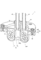
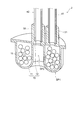
- FIG. 1 is a perspective sectional view showing a gripping tool 1 according to an embodiment.
- the gripping tool 1 according to the embodiment includes a gripping part 10 having flexibility.
- a powder body 15 is provided inside the grip portion 10.
- the grip portion 10 includes a first portion 11 and a second portion 12.
- the first portion 11 contacts the workpiece to be grasped.
- the second portion 12 faces the first portion 11.
- the first portion 11 and the second portion 12 are made of a flexible material such as a silicone resin, a rubber material, or an acrylic resin.
- the powder body 15 is provided in the first space SP ⁇ b> 1 between the first portion 11 and the second portion 12.
- the grip portion 10 is configured by joining a first portion 11 and a second portion 12 via an adhesive, for example.
- the first portion 11 and the second portion 12 may be joined by thermocompression bonding.
- the outer periphery of the first part 11 and the outer periphery of the second part 12 are held by the holding unit 20. As a result, the first space SP1 is separated from the external space.
- the holding part 20 is, for example, an annular shape. By holding only the outer periphery of the gripping part 10 by the holding part 20, the gripping part 10 can be deformed in a line direction connecting the first part 11 and the second part 12 inside the holding part 20.
- the line direction connecting the first portion 11 and the second portion 12 is, for example, the vertical direction.
- the line direction connecting the first part 11 and the second part 12 is a first direction (upward) from the first part 11 toward the second part 12 and a second direction (from the second part 12 toward the first part 11). Lower).
- each embodiment will be described using these “vertical direction”, “upward”, and “downward” based on the positional relationship between the first portion 11 and the second portion 12.
- the holding unit 20 includes a first flange 21 and a second flange 22.
- the first flange 21 abuts on the outer peripheral lower surface of the first portion 11.
- the second flange 22 abuts on the outer peripheral upper surface of the second portion 12.
- the holding part 10 is hold
- FIG. 2 is a perspective cross-sectional view illustrating the grip portion 10 of the grip tool 1 according to the embodiment. In FIG. 2, the first portion 11 and the second portion 12 of the grip portion 10 are shown separately.
- the first portion 11 has a concave portion 11r and a convex portion 11p.
- the recess 11r is recessed upward.
- the recess 11r is provided on the center side of the grip 10.
- the upper surface of the recess 11 r is in contact with the second portion 12.
- the convex portion 11p protrudes downward.
- the convex portion 11p is provided around the concave portion 11r.
- the concave portion 11r and the convex portion 11p are continuous.
- the recess 11r is in contact with the second portion 12.
- the convex portion 11p is separated from the second portion 12 in the vertical direction.
- the first space SP ⁇ b> 1 is formed between the convex portion 11 p and the second portion 12.
- a second space SP2 surrounded by the concave portion 11r and the convex portion 11p is formed below the first portion 11. Specifically, the upper part of the second space SP2 is covered with the recess 11r. The side of the second space SP2 is surrounded by the convex portion 11p. The lower part of the second space SP2 is open. As will be described later, the workpiece to be grasped is positioned below the second space SP2, so that the second space SP2 is closed against the external space.
- the grip portion 10 further includes a first port 31 and a second port 32.
- the first port 31 is connected to the first space SP1.
- the second port 32 passes through the recess 11 r and the second portion 12 of the first portion 11.
- the second port 32 is connected to the second space SP2.
- a first pipe 41 for decompressing the first space SP1 is connected to the first port 31.
- a second pipe 42 for reducing the pressure of the second space SP2 is connected to the second port 32.
- FIG. 3 is a cross-sectional view illustrating a gripping method by the gripping tool 1 according to the embodiment.
- FIG. 3 illustrates a case where the workpiece W to be grasped has a cross section in which three triangles are connected.
- the horizontal position of the gripping unit 10 and the horizontal position of the workpiece W are matched. After matching the position of the grip 10 and the position of the work W, the grip 10 is lowered toward the work W as shown in FIG.
- the grip 10 has flexibility. When the grip portion 10 comes into contact with the workpiece W, the convex portion 11p of the first portion 11 is pushed outward so as to wrap the workpiece W, as shown in FIG. The opened second space SP2 is closed by the work W.
- the lowering of the gripping part 10 stops.
- the first space SP ⁇ b> 1 is decompressed through the first port 31 and the first pipe 41.
- the first space SP1 is depressurized to about 0.1 atm, for example.
- the granular material 15 in the first space SP1 aggregates and solidifies. Thereby, the shape of the gripping part 10 that is in close contact so as to wrap the work W is fixed, and a force for gripping the work W is generated.
- the second space SP2 is depressurized through the second port 32 and the second pipe.
- the second space SP2 is depressurized to about 0.1 atm, for example.
- the workpiece W is attracted toward the second space SP2, and the gripping force is further increased.
- the gripping tool 1 that grips the workpiece W rises.
- the gripping tool 1 moves in the horizontal direction.
- the first space SP1 and the second space SP2 are released to the atmosphere. Thereby, the gripping force is lost, and the workpiece W is released from the gripping tool 1.
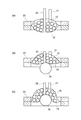
- FIG. 4 is a cross-sectional view illustrating a gripping mechanism of the gripping tool 1 according to the embodiment.
- the grip portion 10 of the grip tool 1 is partially simplified.
- the outer periphery of the gripping part 10 is held by the holding part 20. Therefore, as shown in FIG. 4B, when the gripping portion 10 is brought into contact with the workpiece W, the gripping portion 10 can be deformed upward with respect to the workpiece W.
- the gripping unit 10 is held by the holding unit 20 so as to be deformable upward with respect to the workpiece W. According to this configuration, the gripping force when gripping the workpiece W by the gripping part 10 can be increased.
- FIG. 5 is a perspective view showing a gripping tool 100 according to a conventional example.
- the gripping tool 100 includes a suction pad 101.
- the gripping tool 100 grips the workpiece by bringing the suction pad 101 into contact with and gripping the workpiece to be gripped.
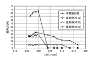
- FIG. 6 shows experimental results representing characteristics of the gripping tool according to the embodiment and the conventional example.
- the horizontal axis represents the curvature of the object surface to be grasped (the reciprocal of the radius of curvature R).
- the vertical axis represents the gripping force at each curvature.
- a plurality of gripping tools 100 and the gripping tool 1 according to the embodiment were used.
- the diameters of the suction pads 101 included in each gripping tool 100 are different from each other.
- the gripping force was measured by the following procedure. First, an object to be grasped is placed at a predetermined position. This object is gripped by a gripping tool. While the force applied to the gripping tool is measured, the gripping tool rises at a constant speed. The gripping tool is raised until the gripping tool is separated from the object. The maximum measured force is recorded. The experiment is repeated three times for each gripping tool. The average of the measured maximum values is taken as the gripping force [N: Newton].
- the gripping tool 100 provided with the suction pad 101 having a diameter of 10 cm, when the surface of the object has a small curvature, the same gripping force as that obtained when the surface was flat was obtained. However, the gripping tool 100 has a problem that the gripping force is small.
- the gripping tool 1 according to the present embodiment has a gripping force substantially equal to that when the surface is flat even when a small curvature exists on the surface of the object.
- the gripping force of the gripping tool 1 according to the embodiment is larger than that of the gripping tool 100 in which the diameter of the suction pad 101 is 10 cm and 30 cm, and a sufficient value is obtained.
- the gripping force of the gripping tool can greatly depend not only on the shape of the gripping tool but also on the shape of the object to be gripped.
- the gripping tool 1 according to the present embodiment is compared with the gripping tool 100 including the suction pad 101 having a diameter of 50 cm.
- the gripping force of the gripping tool 1 is greater than that of the gripping tool 100.
- the gripping force of the gripping tool 100 is greater than that of the gripping tool 1. Therefore, how to quantitatively evaluate the gripping performance of the gripping tool becomes a problem.
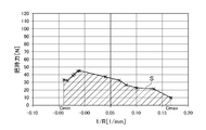
- FIG. 7 is a diagram for explaining a gripping performance evaluation method according to the embodiment.
- the experimental result of the gripping tool 1 according to this embodiment shown in FIG. 6 is used.
- the gripping force of the gripping tool at each curvature is measured while changing the curvature of the object surface.
- an integrated value of the gripping force with respect to the curvature is calculated from the measurement result.
- the calculated integral value is defined as the gripping performance of the gripping tool.
- the gripping performance of the gripping tool can be quantitatively evaluated including the dependency of the gripping force on the shape of the object to be gripped.
- Table 1 below shows the evaluation results of the gripping performance of the gripping tool 100 according to the conventional example and the gripping tool 1 according to the present embodiment.
- the gripping performance of these gripping tools was evaluated using the evaluation method described above based on the experimental results shown in FIG.
- the gripping performance value of the gripping tool 1 according to the present embodiment is larger than the gripping performance value of the gripping tool according to the conventional example. This indicates that the gripping tool 1 according to this embodiment has a gripping performance superior to any gripping tool according to any conventional example.
- the inventors conducted a similar experiment on a plurality of gripping tools 1 having different diameters and shapes of the powder particles 15. The inventors evaluated the gripping performance of each gripping tool 1 using the evaluation method described above.
- FIG. 8 and 9 are experimental results representing the characteristics of the gripping tool 1 according to the embodiment.
- the horizontal axis and vertical axis in FIG. 8 represent the curvature and gripping force, respectively, as in FIG. In FIG. 9, the horizontal axis represents the diameter of the granular material 15, and the vertical axis represents the gripping performance.
- the granular material 15 for example, micro beads, silicone resin beads, coffee beans, glass beads, or the like can be used.
- the spherical first granular material is composed of one material (material A) selected from the group consisting of microbeads, silicon resin beads, coffee beans, and glass beads.
- the square-shaped second granular material is composed of another material (material B) selected from the above group.
- FIG. 8 shows the change in the gripping performance of the gripping tool 1 accompanying the change in the diameter of the first powder and the gripping performance of the gripping tool 1 when the second powder is used.
- the numerical value attached in parentheses beside the material represents the diameter of the first granular material.
- the intermediate value of the minimum diameter and the largest diameter was used as a diameter of the said 2nd granular material.
- the average gripping performance of the gripping tool 100 according to the conventional example that is generally sold is 3.22 [N / mm]. If this result is collated with the experimental result in FIG. 9, it will be understood that the diameter of the gripping tool 100 according to the conventional example corresponds to 1774 ⁇ m. Therefore, by setting the diameter of the powder particles 15 to less than 1774 ⁇ m, the gripping tool 1 having a gripping performance higher than that of the gripping tool according to the average conventional example can be obtained.
- the granular material 15 is spherical and has a diameter of 500 ⁇ m or less, a gripping performance superior to that of the gripping tool 100 according to the conventional example having the highest gripping performance is obtained. I understand that. Therefore, more preferably, the granular material 15 is spherical and has a diameter of 500 ⁇ m or less.
- FIG. 10 is an experimental result illustrating another characteristic of the gripping tool according to the embodiment.
- the experimental result at the time of mixing the granular material 15 from which a diameter mutually differs is represented.
- the range of the diameter of the granular material 15 described above can be suitably used by the gripping tool 1.
- the gripping portion 10 can be deformed upward with respect to the workpiece W.
- the diameter of the granular material 15 greatly affects the amount of deformation of the gripping part 10.
- the contact area between the first portion 11 and the workpiece W increases as the amount of deformation of the grip portion 10 increases. . Therefore, in the gripping tool 1, the gripping performance of the gripping tool 1 can be further improved by setting the diameter of at least a part of the granular material 15 to less than 1774 ⁇ m (more desirably, 500 ⁇ m or less).
- the gripping tool according to the present embodiment is not limited to the one shown in FIGS. As will be described below, various modifications can be applied to the gripping tool according to the embodiment. Also in each gripping tool described below, the gripping performance of the gripping tool can be improved because the hardness of at least a part of the first portion 11 is in the above-described range.
- FIG. 11 is a perspective cross-sectional view illustrating a gripping tool 2 according to a first modification of the embodiment.
- the gripping tool 2 shown in FIG. 11 is different from the gripping tool 1 in that the holding unit 20 is not provided. For this reason, the 1st part 11 and the 2nd part 12 are mutually adhere
- FIG. 12 is a perspective cross-sectional view showing a gripping tool 3 according to a second modification of the embodiment.
- the gripping tool 3 shown in FIG. 12 differs from the gripping tool 1 in the shape of the gripping part 10 and does not have the second port 32.
- the first part 11 is convexly curved downward.
- the second portion 12 is convexly curved upward.
- the granular material is provided in the first space SP ⁇ b> 1 between the first portion 11 and the second portion 12.
- the first portion 11 does not have the concave portion 11r and the convex portion 11p.
- the second space SP2 is not formed below the first portion 11.
- the second port 32 is not provided.
- the gripping portion 10 can be deformed upward with respect to the workpiece W when the workpiece W is gripped, similarly to the mechanism shown in FIG. Thereby, the gripping force by the gripping part 10 can be increased.
- FIG. 13 is a perspective cross-sectional view showing a gripping tool 4 according to a third modification of the embodiment. 13 is different from the gripping tool 3 in that the holding tool 20 is not provided.
- the first portion 11 and the second portion 12 are bonded and fixed to each other on the outer periphery.
- FIG. 14 is a schematic diagram illustrating the gripping system 5 according to the embodiment.
- the gripping system 5 of the embodiment includes a gripping tool 1, a transfer robot 90, a first decompression device 91, a second decompression device 92, and a controller 93.
- the transfer robot 90 has an arm 90a.
- the arm 90a has, for example, a plurality of joints.
- the gripping tool 1 is attached to the tip of the arm 90a.
- the transfer robot 90 operates the arm 90 a in accordance with a command from the controller 93 to grip and transfer the workpiece W.
- the first decompressor 91 and the second decompressor 92 have a vacuum pump.
- the first decompression device 91 is connected to the first pipe 41 of the gripping tool 1 shown in FIG.
- the second decompression device 92 is connected to the second pipe 42 of the gripping tool 1.
- the first decompression device 91 and the second decompression device 92 are driven in accordance with a command from the controller 93. Thereby, the first space SP1 and the second space SP2 are decompressed or opened to the atmosphere.
- the controller 93 includes a CPU (Central Processing Unit), a ROM (Read Only Memory), a non-volatile flash memory, and the like. In the CPU, various arithmetic processes in the controller 93 are executed.
- the ROM stores various control algorithms and various constants necessary for the operation of the gripping system 5.
- the flash memory stores and stores the transfer procedure of the workpiece W, the transfer status, and the like as appropriate.
- the controller 93 sends commands to the transfer robot 90, the first pressure reducing device 91, and the second pressure reducing device 92 according to the transfer procedure stored in the flash memory, and controls these operations.
- the gripping system 5 includes the gripping tool 1 with high gripping performance, the workpiece W can be gripped and transported more reliably.
- the gripping system 5 may include any one of the gripping tools 2 to 4 according to the above-described modifications instead of the gripping tool 1.
- the gripping system 5 may not include the second decompression device 92.
Landscapes
- Engineering & Computer Science (AREA)
- Robotics (AREA)
- Mechanical Engineering (AREA)
- Manipulator (AREA)
Abstract
実施形態に係る把持ツールは、可撓性を有し、内部に複数の粉粒体が設けられた把持部を備える。前記把持ツールは、前記把持部をワークに接触させた状態で、前記把持部の内部を減圧することで前記ワークを把持する。前記複数の粉粒体の少なくとも一部の径は、1774μm未満である。
Description
本発明の実施形態は、把持ツール、把持システム、および把持性能の評価方法に関する。
物体を把持し、当該物体を搬送する把持ツールがある。把持ツールの把持性能は高いことが望ましい。例えば、把持は、大きさや形状が異なる様々な物体をより大きな力で把持することができることが望ましい。
本発明が解決しようとする課題は、把持性能の高い把持ツールと把持システム、および把持性能の評価方法を提供することである。
実施形態に係る把持ツールは、可撓性を有し、内部に複数の粉粒体が設けられた把持部を備える。前記把持ツールは、前記把持部をワークに接触させた状態で、前記把持部の内部を減圧することで前記ワークを把持する。前記複数の粉粒体の少なくとも一部の径は、1774μm未満である。
以下に、本発明の各実施形態について図面を参照しつつ説明する。
図面は模式的または概念的なものであり、各部分の厚みと幅との関係、部分間の大きさの比率などは、必ずしも現実のものと同一とは限らない。同じ部分を表す場合であっても、図面により互いの寸法や比率が異なって表される場合もある。
本願明細書と各図において、既に説明したものと同様の要素には同一の符号を付して詳細な説明は適宜省略する。
図面は模式的または概念的なものであり、各部分の厚みと幅との関係、部分間の大きさの比率などは、必ずしも現実のものと同一とは限らない。同じ部分を表す場合であっても、図面により互いの寸法や比率が異なって表される場合もある。
本願明細書と各図において、既に説明したものと同様の要素には同一の符号を付して詳細な説明は適宜省略する。
図1は、実施形態に係る把持ツール1を表す斜視断面図である。
実施形態に係る把持ツール1は、可撓性を有する把持部10を備える。把持部10の内部には、粉粒体15が設けられている。
実施形態に係る把持ツール1は、可撓性を有する把持部10を備える。把持部10の内部には、粉粒体15が設けられている。
より具体的には、把持部10は、第1部分11と、第2部分12と、を有する。第1部分11は、把持対象のワークに接触する。第2部分12は、第1部分11と対向する。第1部分11および第2部分12は、シリコーン樹脂、ゴム材料、またはアクリル樹脂などの可撓性を有する材料で構成される。粉粒体15は、第1部分11と第2部分12との間の第1空間SP1に設けられている。把持部10は、第1部分11と第2部分12とが、例えば、接着剤を介して接合されて構成されている。第1部分11と第2部分12とは、熱圧着により接合されていてもよい。
第1部分11の外周および第2部分12の外周は、保持部20によって保持されている。これにより第1空間SP1が、外部の空間と隔てられる。保持部20は、例えば円環状である。保持部20によって把持部10の外周のみが保持されることで、把持部10は、保持部20の内側において第1部分11と第2部分12とを結ぶ線方向に変形できる。
第1部分11と第2部分12とを結ぶ線方向は、例えば、上下方向である。第1部分11と第2部分12とを結ぶ線方向は、第1部分11から第2部分12に向かう第1方向(上方)と、第2部分12から第1部分11に向かう第2方向(下方)と、を含む。以下では、第1部分11と第2部分12との位置関係に基づくこれらの「上下方向」「上方」「下方」を用いて、各実施形態の説明を行う。
一例として、保持部20は、第1フランジ21および第2フランジ22を有する。第1フランジ21は、第1部分11の外周下面に当接する。第2フランジ22は、第2部分12の外周上面に当接する。第1フランジ21と第2フランジ22を、ネジ等の締結具25によって締結することで、把持部10が保持される。
図2は、実施形態に係る把持ツール1の把持部10を表す斜視断面図である。
図2では、把持部10の第1部分11と第2部分12が、分離して表されている。
図2では、把持部10の第1部分11と第2部分12が、分離して表されている。
図2に表すように、第1部分11は、凹部11rおよび凸部11pを有する。凹部11rは、上方に向けて窪んでいる。凹部11rは、把持部10の中心側に設けられている。凹部11rの上面は、第2部分12と接している。凸部11pは、下方に向けて突出している。凸部11pは、凹部11rの周りに設けられている。凹部11rと凸部11pは、連続している。
凹部11rは、第2部分12と接する。凸部11pは、第2部分12と上下方向において離間している。図1および図2に例示した把持ツール1では、第1空間SP1は、凸部11pと第2部分12との間に形成される。
第1部分11の下方には、凹部11rおよび凸部11pによって囲まれた第2空間SP2が形成される。具体的には、第2空間SP2の上方は、凹部11rによって覆われている。第2空間SP2の側方は、凸部11pによって囲まれている。第2空間SP2の下方は開けている。後述するように、把持対象のワークが第2空間SP2の下方に位置することで、第2空間SP2が外部空間に対して塞がれる。
図1および図2に表すように、把持部10は、第1ポート31および第2ポート32をさらに有する。第1ポート31は、第1空間SP1と接続されている。第2ポート32は、第1部分11の凹部11rおよび第2部分12を貫通している。第2ポート32は、第2空間SP2と接続されている。第1ポート31には、第1空間SP1を減圧するための第1配管41が接続される。第2ポート32には、第2空間SP2を減圧するための第2配管42が接続される。
図3は、実施形態に係る把持ツール1による把持方法を表す断面図である。
図3では、把持対象のワークWが、三角形が3個連接した断面を有する場合を例示している。
図3では、把持対象のワークWが、三角形が3個連接した断面を有する場合を例示している。
まず、把持部10の水平方向における位置とワークWの水平方向における位置が合わせられる。把持部10の位置とワークWの位置とを合わせた後、図3(a)に表すように、把持部10をワークWに向かって下降させる。
把持部10は、可撓性を有する。把持部10がワークWに接触すると、図3(b)に表すように、第1部分11の凸部11pが、ワークWを包み込むように外方に押し広げられる。開けていた第2空間SP2が、ワークWによって塞がれる。
次に、把持部10の下降が停止する。図3(c)に表すように、第1ポート31および第1配管41を通して第1空間SP1が減圧される。第1空間SP1は、例えば0.1気圧程度に減圧される。このとき、第1空間SP1の粉粒体15が凝集して固化する。これにより、ワークWを包み込むように密着している把持部10の形状が固定され、ワークWを把持する力が生じる。
次に、図3(d)に表すように、第2ポート32および第2配管42を通して第2空間SP2が減圧される。第2空間SP2は、例えば0.1気圧程度に減圧される。これにより、ワークWが、第2空間SP2に向けて吸着され、把持力がさらに高められる。
その後、ワークWを把持する把持ツール1が上昇する。把持ツール1が水平方向に移動する。ワークWが所定の位置まで搬送された後は、第1空間SP1および第2空間SP2が大気開放される。これにより、把持力が無くなり、ワークWが把持ツール1から放れる。以上の方法により、把持対象のワークWが、所定の位置まで搬送される。
図4は、実施形態に係る把持ツール1の把持メカニズムを表す断面図である。
図4では、把持ツール1の把持部10が一部簡略化して表されている。
図4では、把持ツール1の把持部10が一部簡略化して表されている。
実施形態に係る把持ツール1では、図4(a)に表すように、把持部10の外周が保持部20によって保持されている。従って、図4(b)に表すように、把持部10をワークWに接触させた際に、把持部10がワークWに対して上方に向けて変形できる。
この状態で、第1ポート31および第2ポート32を通して吸気する。これにより、図4(c)に表すように、把持部10がさらにワークWに対して上方に向けて変形しつつ、把持部10とワークWとの接触面積が増加していく。
以上で説明したように、把持部10は、ワークWに対して上方に向けて変形可能なように保持部20に保持される。この構成によれば、把持部10によってワークWを把持した際の把持力を高めることができる。
ここで、図5を参照しつつ、一般に販売されている従来例に係る把持ツール100について説明する。また、図6を参照しつつ、本実施形態に係る把持ツール1と、従来例に係る把持ツール100と、の把持力の比較結果について説明する。
図5は、従来例に係る把持ツール100を表す斜視図である。
図5に表すように、把持ツール100は、吸着パッド101を備える。把持ツール100は、吸着パッド101を、把持対象のワークに当接させて吸着させることで、当該ワークを把持する。
図5に表すように、把持ツール100は、吸着パッド101を備える。把持ツール100は、吸着パッド101を、把持対象のワークに当接させて吸着させることで、当該ワークを把持する。
図6は、実施形態および従来例に係る把持ツールの特性を表す実験結果である。
図6において、横軸は、把持対象の物体表面の曲率(曲率半径Rの逆数)を表す。縦軸は、各曲率における把持力を表す。実験では、複数の把持ツール100および実施形態に係る把持ツール1を用いた。それぞれの把持ツール100に含まれる吸着パッド101の直径は、互いに異なる。
図6において、横軸は、把持対象の物体表面の曲率(曲率半径Rの逆数)を表す。縦軸は、各曲率における把持力を表す。実験では、複数の把持ツール100および実施形態に係る把持ツール1を用いた。それぞれの把持ツール100に含まれる吸着パッド101の直径は、互いに異なる。
この実験では、把持力を以下の手順で測定した。
まず、把持対象の物体が所定の位置に置かれる。この物体が把持ツールで把持される。把持ツールに加わる力が測定されつつ、把持ツールが一定の速度で上昇する。把持ツールが物体から離れるまで把持ツールが上昇する。測定された力の最大値が記録される。それぞれの把持ツールについて3回実験が繰り返される。測定された最大値の平均が把持力[N:ニュートン]とされる。
まず、把持対象の物体が所定の位置に置かれる。この物体が把持ツールで把持される。把持ツールに加わる力が測定されつつ、把持ツールが一定の速度で上昇する。把持ツールが物体から離れるまで把持ツールが上昇する。測定された力の最大値が記録される。それぞれの把持ツールについて3回実験が繰り返される。測定された最大値の平均が把持力[N:ニュートン]とされる。
図6に表すように、直径30cmの吸着パッド101を備えた把持ツール100および直径50cmの吸着パッド101を備えた把持ツール100については、表面が比較的平坦なワークに対して大きな把持力が得られた。ワークの表面に曲率が在る場合、これらの把持ツール100の把持力は急激に低下し、ワークを把持することが困難であった。
直径10cmの吸着パッド101を備えた把持ツール100については、物体の表面に小さな曲率が存在する場合、表面が平坦な場合と同様の把持力が得られた。しかし、この把持ツール100については、把持力が小さいという課題が存在する。
本実施形態に係る把持ツール1は、物体の表面に小さな曲率が存在する場合でも、表面が平坦なときと略同等の把持力が得られた。実施形態に係る把持ツール1の把持力は、吸着パッド101の直径が10cmおよび30cmの把持ツール100よりも大きく、十分な値が得られた。
図6から分かるように、把持ツールの把持力は、把持ツールの形態だけではなく、把持対象の物体の形状にも大きく依存しうる。例えば、本実施形態に係る把持ツール1と、直径50cmの吸着パッド101を備えた把持ツール100と、を比較する。物体の表面に曲率が存在する場合は、把持ツール1の把持力が把持ツール100よりも大きい。物体の表面が平坦な場合には、把持ツール100の把持力が把持ツール1よりも大きい。従って、把持ツールの把持性能を、どのように定量的に評価するかが課題となる。
本願発明者らは、以下で説明する方法を、把持ツールにおける把持性能の評価方法として用いることを考案した。
図7は、実施形態に係る把持性能の評価方法を説明するための図である。
図7では、図6に表した、本実施形態に係る把持ツール1の実験結果を用いている。
図7は、実施形態に係る把持性能の評価方法を説明するための図である。
図7では、図6に表した、本実施形態に係る把持ツール1の実験結果を用いている。
まず、図6の実験結果と同様に、物体表面の曲率を変化させながら、それぞれの曲率における把持ツールの把持力が測定される。次に、測定結果から、曲率に対する把持力の積分値が算出される。
これは、図7に表す領域Sの面積を算出することに相当する。領域Sは、曲率と把持力の実験結果のプロットに対して、横軸と、1/R=Cminと、1/R=Cmaxと、把持力同士を結ぶ線分と、で囲まれる。Cminは、把持力の測定を行った曲率1/Rのうち、最小の曲率を表す。Cmaxは、把持力の測定を行った曲率1/Rのうち、最大の曲率を表す。
そして、算出された積分値が、その把持ツールにおける把持性能と定義される。この評価方法によれば、把持対象の物体の形状に対する把持力の依存性を含めて、把持ツールの把持性能を定量的に評価できる。
以下の表1は、従来例に係る把持ツール100および本実施形態に係る把持ツール1の把持性能の評価結果を表す。これらの把持ツールの把持性能は、図6に表した実験結果を基に、上述した評価方法を用いて評価された。

表1から、本実施形態に係る把持ツール1の把持性能の値は、従来例に係る把持ツールの把持性能の値よりも大きいことが分かる。これは、本実施形態に係る把持ツール1が、いずれの従来例に係る把持ツールよりも優れた把持性能を有することを示している。
発明者らがさらに実験を行った結果、把持部10内部の粉粒体15の径および形状が、この把持性能に影響を与えることを発見した。そこで、発明者らは、粉粒体15の径および形状が互いに異なる複数の把持ツール1について同様の実験を行った。発明者らは、それぞれの把持ツール1の把持性能を、上述した評価方法を用いて評価した。
図8および図9は、実施形態に係る把持ツール1の特性を表す実験結果である。
図8における横軸および縦軸は、図6と同様に、それぞれ曲率および把持力を表す。図9において、横軸は粉粒体15の径を表し、縦軸は把持性能を表している。
図8における横軸および縦軸は、図6と同様に、それぞれ曲率および把持力を表す。図9において、横軸は粉粒体15の径を表し、縦軸は把持性能を表している。
粉粒体15として、例えば、マイクロビーズ、シリコーン樹脂ビーズ、コーヒ豆、またはガラスビーズ等を用いることができる。実験では、球状の第1粉粒体と、角張った第2粉粒体と、が使用された。球状の第1粉粒体は、マイクロビーズ、シリコン樹脂ビーズ、コーヒ豆、およびガラスビーズからなる群より選択された1つの材料(材料A)から構成される。角張った第2粉粒体は、上記の群から選択された別の1つの材料(材料B)から構成される。図8は、第1粉粒体の径の変化に伴う把持ツール1の把持性能の変化、及び、第2粉粒体を用いた場合の把持ツール1の把持性能が表している。図8において、材料の横に括弧書きで付された数値は、第1粉粒体の径を表している。第2粉粒体については、最小の径と最大の径との中間値を、当該第2粉粒体の径として用いた。
図8の実験結果から、粉粒体15の径が小さいほど、それぞれの曲率において高い把持力が得られていることが分かる。第1粉粒体と第2粉粒体15については、第1粉粒体の方が、第2粉粒体よりも高い把持力が得られていることが分かる。この図8の実験結果をもとに、それぞれの径について把持性能を算出した。図9は、この算出結果を表す。図9の結果から、粉粒体15が球状であり、粉粒体15の径が小さいほど、高い把持性能が得られていることが分かる。
表1に表したように、一般に販売されている従来例に係る把持ツール100における平均的な把持性能は、3.22[N/mm]である。この結果を、図9における実験結果に照らし合わせると、従来例に係る把持ツール100における径は、1774μmに相当することが分かる。従って、粉粒体15の径を、1774μm未満とすることで、平均的な従来例に係る把持ツールよりも把持性能の高い把持ツール1が得られる。
表1および図9の結果から、粉粒体15が球状であり、且つ径が500μm以下の場合、従来例に係る把持ツール100のうち最も把持性能が高いものよりも優れた把持性能が得られることが分かる。従って、より望ましくは、粉粒体15は球状であり、その径は500μm以下である。
図10は、実施形態に係る把持ツールの他の特性を表す実験結果である。
図10では、径が互いに異なる粉粒体15を混ぜた場合の実験結果を表している。ここでは、500μmの径を有する粉粒体と、900μmの径を有する粉粒体と、を混ぜ、500μmの径を有する粉粒体(主材料)の割合を変化させて実験した。
図10では、径が互いに異なる粉粒体15を混ぜた場合の実験結果を表している。ここでは、500μmの径を有する粉粒体と、900μmの径を有する粉粒体と、を混ぜ、500μmの径を有する粉粒体(主材料)の割合を変化させて実験した。
図10の実験結果から、径が異なる粉粒体を混ぜ合わせた場合でも、把持力に大きな変化は見られなかった。この結果は、複数の粉粒体15の少なくとも一部の径が、上述した範囲にあれば、把持性能の高い把持ツール1が得られることを示している。
上述した粉粒体15の径の範囲は、把持ツール1により好適に用いることができる。図4の把持メカニズムに表したように、把持ツール1では、把持部10がワークWに対して上方に向けて変形可能である。把持部10がワークWに対して上方に向けて変形可能である場合、粉粒体15の径が、把持部10の変形量により大きく影響する。把持部10の変形量が大きいほど、第1部分11とワークWとの接触面積が増加する。。従って、把持ツール1において、粉粒体15の少なくとも一部の径を、1774μm未満(より望ましくは500μm以下)に設定することで、把持ツール1の把持性能をさらに向上させることができる。
本実施形態に係る把持ツールは、図1および図2に表したものに限定されない。以下で説明するように、実施形態に係る把持ツールには、種々の変形を適用できる。以下で説明する各把持ツールにおいても、第1部分11の少なくとも一部の硬度が、上述した範囲にあることで、把持ツールの把持性能を向上させることができる。
図11は、実施形態の第1変形例に係る把持ツール2を表す斜視断面図である。
図11に表した把持ツール2は、保持部20を備えていない点で把持ツール1と異なる。このため、第1部分11と第2部分12は、それぞれの外周において、互いに接着されて固定されている。
図11に表した把持ツール2は、保持部20を備えていない点で把持ツール1と異なる。このため、第1部分11と第2部分12は、それぞれの外周において、互いに接着されて固定されている。
図12は、実施形態の第2変形例に係る把持ツール3を表す斜視断面図である。
図12に表した把持ツール3は、把持ツール1と比べて、把持部10の形状が異なり、第2ポート32を有していない。
図12に表した把持ツール3は、把持ツール1と比べて、把持部10の形状が異なり、第2ポート32を有していない。
把持部10において、第1部分11は下方に向けて凸に湾曲している。第2部分12は上方に向けて凸に湾曲している。粉粒体は、第1部分11と第2部分12との間の第1空間SP1に設けられている。
図1に表した把持ツール1と異なり、把持ツール3においては、第1部分11が凹部11rおよび凸部11pを有していない。このため、把持ツール3では、第1部分11の下方に第2空間SP2が形成されていない。第2ポート32が設けられていない。本変形例に係る把持ツール3においても、図3に表したメカニズムと同様に、ワークWを把持した際に把持部10がワークWに対して上方に向けて変形可能である。これにより、把持部10による把持力を高めることができる。
図13は、実施形態の第3変形例に係る把持ツール4を表す斜視断面図である。
図13に表した把持ツール4は、保持部20を備えていない点で、把持ツール3と異なる。第1部分11と第2部分12は、それぞれの外周において、互いに接着されて固定されている。
図13に表した把持ツール4は、保持部20を備えていない点で、把持ツール3と異なる。第1部分11と第2部分12は、それぞれの外周において、互いに接着されて固定されている。
図14は、実施形態に係る把持システム5を表す概略図である。
実施形態の把持システム5は、把持ツール1、搬送ロボット90、第1減圧装置91、第2減圧装置92、およびコントローラ93を備える。
実施形態の把持システム5は、把持ツール1、搬送ロボット90、第1減圧装置91、第2減圧装置92、およびコントローラ93を備える。
搬送ロボット90は、アーム90aを有する。アーム90aは、例えば複数の関節を有する。アーム90aの先端に、把持ツール1が取り付けられている。搬送ロボット90は、コントローラ93からの指令に従ってアーム90aを動作させ、ワークWの把持および搬送を行う。
第1減圧装置91および第2減圧装置92は、真空ポンプを有する。第1減圧装置91は、図1に表した把持ツール1の第1配管41と接続される。第2減圧装置92は、把持ツール1の第2配管42と接続される。コントローラ93からの指令に従って第1減圧装置91および第2減圧装置92が駆動される。これにより、第1空間SP1および第2空間SP2が減圧または大気開放される。
コントローラ93は、CPU(Central Processing Unit)や、ROM(Read Only Memory)、不揮発性のフラッシュメモリなどを有する。CPUでは、コントローラ93における各種演算処理が実行される。ROMには、把持システム5の動作に必要な各種制御アリゴリズムや各種定数等が記憶される。フラッシュメモリには、ワークWの搬送手順や、搬送状況等が適宜記憶して保存される。
コントローラ93は、フラッシュメモリに記憶されている搬送手順に従って、搬送ロボット90、第1減圧装置91、および第2減圧装置92に指令を送出し、これらの動作を制御する。
把持システム5が、把持性能の高い把持ツール1を備えることで、ワークWをより確実に把持し、搬送することが可能となる。
実施形態に係る把持システム5は、把持ツール1に代えて、上述した変形例に係る把持ツール2~4のいずれかを備えていても良い。把持システム5が把持ツール3または4を備える場合、把持システム5は、第2減圧装置92を備えていなくても良い。
以上、本発明のいくつかの実施形態を例示したが、これらの実施形態は、例として提示したものであり、発明の範囲を限定することは意図していない。これら新規な実施形態は、その他の様々な形態で実施されることが可能であり、発明の要旨を逸脱しない範囲で、種々の省略、置き換え、変更などを行うことができる。これら実施形態やその変形例は、発明の範囲や要旨に含まれるとともに、請求の範囲に記載された発明とその均等の範囲に含まれる。また、前述の各実施形態は、相互に組み合わせて実施することができる。
Claims (9)
- 可撓性を有し、内部に複数の粉粒体が設けられた把持部を備え、
前記把持部をワークに接触させた状態で、前記把持部の内部を減圧することで前記ワークを把持する把持ツールであって、
前記複数の粉粒体の少なくとも一部の径は、1774μm未満である把持ツール。 - 前記複数の粉粒体の前記少なくとも一部の径は、500μm以下であり、
前記複数の粉粒体の前記少なくとも一部は、球状である請求項1記載の把持ツール。 - 前記把持部は、
前記ワークに接触する第1部分と、
前記第1部分と対向する第2部分と、
を有し、
前記複数の粉粒体は、前記第1部分と前記第2部分との間の第1空間に設けられた請求項1または2に記載の把持ツール。 - 前記第1部分は、
前記第1部分から前記第2部分に向かう第1方向に窪んだ凹部と、
前記凹部の周りに設けられ、前記第1方向と反対の第2方向に突出した凸部と、
を有し、
前記複数の粉粒体は、前記凸部と前記第2部分との間に設けられた請求項3記載の把持ツール。 - 前記第1空間に接続され、前記第1空間を減圧するための配管が接続される第1ポートと、
前記凹部および前記凸部に囲まれた第2空間に接続され、前記第2空間を減圧するための配管が接続される第2ポートと、
をさらに備えた請求項4記載の把持ツール。 - 前記第1部分の外周および前記第2部分の外周を保持する保持部をさらに備え、
前記把持部は、前記第1部分と前記第2部分とを結ぶ線方向に変形可能に構成された請求項1~5のいずれか1つに記載の把持ツール。 - アームを有するロボット機構と、
前記アームの先端に取り付けられた、請求項1~6のいずれか1つに記載の前記把持ツールと、
前記第1空間に接続され、前記第1空間を減圧するための第1減圧装置と、
前記ロボット機構および前記第1減圧装置の動作を制御するコントローラと、
を備えた把持システム。 - 物体を把持して持ち上げる把持ツールにおける把持性能の評価方法であって、
把持対象の物体の曲率を変化させながら、それぞれの前記曲率における前記把持ツールの把持力を測定し、
前記曲率に対する前記把持力の積分値を前記把持性能と定義する評価方法。 - 前記把持ツールは、可撓性を有し、内部に複数の粉粒体が設けられた把持部を備え、
前記粉粒体の径を変化させた際の、それぞれの径における前記把持性能を評価する請求項8記載の評価方法。
Priority Applications (4)
| Application Number | Priority Date | Filing Date | Title |
|---|---|---|---|
| CN201780058520.XA CN109789562B (zh) | 2017-03-13 | 2017-09-25 | 把持工具、把持系统、以及把持性能的评价方法 |
| CN202210890958.7A CN115070812A (zh) | 2017-03-13 | 2017-09-25 | 把持工具以及把持系统 |
| US16/360,877 US10766150B2 (en) | 2017-03-13 | 2019-03-21 | Gripping tool, gripping system, and evaluation method of gripping performance |
| US16/983,291 US11389973B2 (en) | 2017-03-13 | 2020-08-03 | Gripping tool, gripping system, and evaluation method of gripping performance |
Applications Claiming Priority (2)
| Application Number | Priority Date | Filing Date | Title |
|---|---|---|---|
| JP2017047885A JP6588935B2 (ja) | 2017-03-13 | 2017-03-13 | 把持ツール、把持システム、および把持性能の評価方法 |
| JP2017-047885 | 2017-03-13 |
Related Child Applications (1)
| Application Number | Title | Priority Date | Filing Date |
|---|---|---|---|
| US16/360,877 Continuation US10766150B2 (en) | 2017-03-13 | 2019-03-21 | Gripping tool, gripping system, and evaluation method of gripping performance |
Publications (1)
| Publication Number | Publication Date |
|---|---|
| WO2018168029A1 true WO2018168029A1 (ja) | 2018-09-20 |
Family
ID=63521932
Family Applications (1)
| Application Number | Title | Priority Date | Filing Date |
|---|---|---|---|
| PCT/JP2017/034441 Ceased WO2018168029A1 (ja) | 2017-03-13 | 2017-09-25 | 把持ツール、把持システム、および把持性能の評価方法 |
Country Status (4)
| Country | Link |
|---|---|
| US (2) | US10766150B2 (ja) |
| JP (1) | JP6588935B2 (ja) |
| CN (2) | CN109789562B (ja) |
| WO (1) | WO2018168029A1 (ja) |
Families Citing this family (6)
| Publication number | Priority date | Publication date | Assignee | Title |
|---|---|---|---|---|
| CN110654976B (zh) * | 2019-09-10 | 2020-10-30 | 东阳市智享机械科技有限公司 | 一种双水平面不同的混凝土防划损支承块吊具 |
| US11260542B2 (en) | 2019-10-31 | 2022-03-01 | GM Global Technology Operations LLC | Universal vacuum cup and method of lifting an object |
| KR102402899B1 (ko) * | 2020-08-24 | 2022-05-27 | 한국기계연구원 | 흡착 유닛, 흡착 유닛 제조방법 및 흡착장치 |
| KR102411453B1 (ko) * | 2020-08-24 | 2022-06-22 | 한국기계연구원 | 흡착 유닛, 흡착 유닛 제어방법 및 흡착장치 |
| US11351678B1 (en) * | 2020-03-10 | 2022-06-07 | Amazon Technologies, Inc. | Dynamically adjustable suction cups |
| KR102392609B1 (ko) | 2020-11-30 | 2022-05-02 | 한국과학기술연구원 | 로봇 팜 |
Citations (2)
| Publication number | Priority date | Publication date | Assignee | Title |
|---|---|---|---|---|
| JP2012176476A (ja) * | 2011-02-28 | 2012-09-13 | Ihi Corp | 形状自在な吸着グリッパとこれによる把持方法 |
| JP2016097496A (ja) * | 2014-11-26 | 2016-05-30 | アルパイン株式会社 | 吸着保持装置 |
Family Cites Families (15)
| Publication number | Priority date | Publication date | Assignee | Title |
|---|---|---|---|---|
| US3318629A (en) * | 1965-04-09 | 1967-05-09 | Jr Richard W Brandt | Tree-clamping jaws with deformable pads containing granular material |
| FR2431635A1 (fr) * | 1978-07-20 | 1980-02-15 | Sgn Soc Gen Tech Nouvelle | Dispositif de prehension par ventouse |
| US4561686A (en) * | 1983-08-22 | 1985-12-31 | Raymond Atchley | End effector |
| US6846029B1 (en) * | 2001-08-09 | 2005-01-25 | Gary Dean Ragner | Torus-shaped mechanical gripper |
| WO2006078841A1 (en) * | 2005-01-21 | 2006-07-27 | President And Fellows Of Harvard College | Systems and methods for forming fluidic droplets encapsulated in particles such as colloidal particles |
| US7997554B2 (en) * | 2008-03-28 | 2011-08-16 | Carnevali Jeffrey D | Adaptive mounting structure |
| US20100054903A1 (en) * | 2008-09-03 | 2010-03-04 | Christopher Vernon Jones | Method and Device for Manipulating an Object |
| US8548626B2 (en) * | 2009-09-03 | 2013-10-01 | Irobot Corporation | Method and device for manipulating an object |
| US8882165B2 (en) * | 2010-04-15 | 2014-11-11 | Cornell University | Gripping and releasing apparatus and method |
| JP5130320B2 (ja) * | 2010-04-28 | 2013-01-30 | トヨタ自動車株式会社 | 把持装置 |
| JP5765248B2 (ja) * | 2012-01-16 | 2015-08-19 | トヨタ自動車株式会社 | 当接部の製造方法 |
| JP2013220508A (ja) * | 2012-04-17 | 2013-10-28 | Ihi Corp | 汎用ロボットハンド |
| CN202895237U (zh) * | 2012-11-29 | 2013-04-24 | 浙江纺织服装职业技术学院 | 一种机器人用软指移物机构 |
| CN203665546U (zh) * | 2014-01-18 | 2014-06-25 | 黑龙江工程学院 | 基于小颗粒物真空状态转换的被动式通用机器手 |
| WO2018088046A1 (ja) | 2016-11-09 | 2018-05-17 | 株式会社 東芝 | 把持ツールおよび把持システム |
-
2017
- 2017-03-13 JP JP2017047885A patent/JP6588935B2/ja active Active
- 2017-09-25 CN CN201780058520.XA patent/CN109789562B/zh active Active
- 2017-09-25 CN CN202210890958.7A patent/CN115070812A/zh active Pending
- 2017-09-25 WO PCT/JP2017/034441 patent/WO2018168029A1/ja not_active Ceased
-
2019
- 2019-03-21 US US16/360,877 patent/US10766150B2/en active Active
-
2020
- 2020-08-03 US US16/983,291 patent/US11389973B2/en active Active
Patent Citations (2)
| Publication number | Priority date | Publication date | Assignee | Title |
|---|---|---|---|---|
| JP2012176476A (ja) * | 2011-02-28 | 2012-09-13 | Ihi Corp | 形状自在な吸着グリッパとこれによる把持方法 |
| JP2016097496A (ja) * | 2014-11-26 | 2016-05-30 | アルパイン株式会社 | 吸着保持装置 |
Also Published As
| Publication number | Publication date |
|---|---|
| CN109789562B (zh) | 2022-08-16 |
| JP2018149636A (ja) | 2018-09-27 |
| US20200361097A1 (en) | 2020-11-19 |
| US20190217484A1 (en) | 2019-07-18 |
| US11389973B2 (en) | 2022-07-19 |
| CN109789562A (zh) | 2019-05-21 |
| US10766150B2 (en) | 2020-09-08 |
| JP6588935B2 (ja) | 2019-10-09 |
| CN115070812A (zh) | 2022-09-20 |
Similar Documents
| Publication | Publication Date | Title |
|---|---|---|
| JP6588935B2 (ja) | 把持ツール、把持システム、および把持性能の評価方法 | |
| JP6588949B2 (ja) | 把持ツール、把持システム、および樹脂部材の製造方法 | |
| CN114734472B (zh) | 把持工具以及把持系统 | |
| CN109789564B (zh) | 把持工具以及把持系统 | |
| CN109789565B (zh) | 把持工具、把持系统、以及把持部的制造方法 | |
| JP6470331B2 (ja) | 把持ツール、把持システム、および把持性能の評価方法 | |
| JP2015202543A (ja) | 物体把持装置 | |
| WO2019065120A1 (ja) | 把持ツールおよび把持システム | |
| JP6686218B2 (ja) | 把持ツール及び把持システム | |
| JP7022083B2 (ja) | 把持ツール及び把持システム | |
| JP2019214123A (ja) | 把持ツール、把持システム、および樹脂部材の製造方法 | |
| JP7013183B2 (ja) | 把持ツールおよび把持システム | |
| JP2019055480A5 (ja) | 把持ツール及び把持システム |
Legal Events
| Date | Code | Title | Description |
|---|---|---|---|
| 121 | Ep: the epo has been informed by wipo that ep was designated in this application |
Ref document number: 17900490 Country of ref document: EP Kind code of ref document: A1 |
|
| NENP | Non-entry into the national phase |
Ref country code: DE |
|
| 122 | Ep: pct application non-entry in european phase |
Ref document number: 17900490 Country of ref document: EP Kind code of ref document: A1 |