WO2018166205A1 - 一种基于多绕组变压器的电池组均衡器模块化系统及方法 - Google Patents
一种基于多绕组变压器的电池组均衡器模块化系统及方法 Download PDFInfo
- Publication number
- WO2018166205A1 WO2018166205A1 PCT/CN2017/106903 CN2017106903W WO2018166205A1 WO 2018166205 A1 WO2018166205 A1 WO 2018166205A1 CN 2017106903 W CN2017106903 W CN 2017106903W WO 2018166205 A1 WO2018166205 A1 WO 2018166205A1
- Authority
- WO
- WIPO (PCT)
- Prior art keywords
- transformer
- modules
- winding
- odd
- battery pack
- Prior art date
- Legal status (The legal status is an assumption and is not a legal conclusion. Google has not performed a legal analysis and makes no representation as to the accuracy of the status listed.)
- Ceased
Links
Images




Classifications
-
- H—ELECTRICITY
- H02—GENERATION; CONVERSION OR DISTRIBUTION OF ELECTRIC POWER
- H02J—ELECTRIC POWER NETWORKS; CIRCUIT ARRANGEMENTS OR SYSTEMS FOR SUPPLYING OR DISTRIBUTING ELECTRIC POWER; SYSTEMS FOR STORING ELECTRIC ENERGY
- H02J7/00—Circuit arrangements for charging or discharging batteries or for supplying loads from batteries
- H02J7/50—Circuit arrangements for charging or discharging batteries or for supplying loads from batteries acting upon multiple batteries simultaneously or sequentially
- H02J7/52—Circuit arrangements for charging or discharging batteries or for supplying loads from batteries acting upon multiple batteries simultaneously or sequentially for charge balancing, e.g. equalisation of charge between batteries
- H02J7/56—Active balancing, e.g. using capacitor-based, inductor-based or DC-DC converters
-
- H—ELECTRICITY
- H02—GENERATION; CONVERSION OR DISTRIBUTION OF ELECTRIC POWER
- H02J—ELECTRIC POWER NETWORKS; CIRCUIT ARRANGEMENTS OR SYSTEMS FOR SUPPLYING OR DISTRIBUTING ELECTRIC POWER; SYSTEMS FOR STORING ELECTRIC ENERGY
- H02J7/00—Circuit arrangements for charging or discharging batteries or for supplying loads from batteries
- H02J7/50—Circuit arrangements for charging or discharging batteries or for supplying loads from batteries acting upon multiple batteries simultaneously or sequentially
- H02J7/52—Circuit arrangements for charging or discharging batteries or for supplying loads from batteries acting upon multiple batteries simultaneously or sequentially for charge balancing, e.g. equalisation of charge between batteries
-
- H—ELECTRICITY
- H02—GENERATION; CONVERSION OR DISTRIBUTION OF ELECTRIC POWER
- H02J—ELECTRIC POWER NETWORKS; CIRCUIT ARRANGEMENTS OR SYSTEMS FOR SUPPLYING OR DISTRIBUTING ELECTRIC POWER; SYSTEMS FOR STORING ELECTRIC ENERGY
- H02J7/00—Circuit arrangements for charging or discharging batteries or for supplying loads from batteries
- H02J7/50—Circuit arrangements for charging or discharging batteries or for supplying loads from batteries acting upon multiple batteries simultaneously or sequentially
- H02J7/52—Circuit arrangements for charging or discharging batteries or for supplying loads from batteries acting upon multiple batteries simultaneously or sequentially for charge balancing, e.g. equalisation of charge between batteries
- H02J7/54—Passive balancing, e.g. using resistors or parallel MOSFETs
-
- Y—GENERAL TAGGING OF NEW TECHNOLOGICAL DEVELOPMENTS; GENERAL TAGGING OF CROSS-SECTIONAL TECHNOLOGIES SPANNING OVER SEVERAL SECTIONS OF THE IPC; TECHNICAL SUBJECTS COVERED BY FORMER USPC CROSS-REFERENCE ART COLLECTIONS [XRACs] AND DIGESTS
- Y02—TECHNOLOGIES OR APPLICATIONS FOR MITIGATION OR ADAPTATION AGAINST CLIMATE CHANGE
- Y02E—REDUCTION OF GREENHOUSE GAS [GHG] EMISSIONS, RELATED TO ENERGY GENERATION, TRANSMISSION OR DISTRIBUTION
- Y02E60/00—Enabling technologies; Technologies with a potential or indirect contribution to GHG emissions mitigation
- Y02E60/10—Energy storage using batteries
Definitions
- the invention relates to a modular system and method for a battery equalizer based on a multi-winding transformer.
- Lithium-ion batteries are widely used in electric vehicles because of their advantages of no memory effect, high energy density, high cell voltage and good safety.
- a large number of lithium ion battery cells need to be used in series or in parallel.
- the internal resistance and capacity between battery cells are not completely consistent.
- these inconsistencies will gradually accumulate and cause imbalance of voltages of different series battery cells, which may cause overcharging or overdischarging of a certain battery cell, reducing the available capacity and circulation of the battery pack. Lifetime and even damage to the battery pack. Therefore, series battery packs require equalization circuitry to balance the inconsistencies between battery cell voltages.
- the active equalization method is mainly based on capacitors, inductors or transformers to transfer energy from a higher voltage battery cell to a lower voltage battery cell.
- the transformer-based equalization method has the advantages of good isolation performance, high efficiency, simple control and fast equalization speed.
- the Chinese invention patent proposes a series battery equalization circuit based on a symmetric multi-winding transformer structure.
- the equalization circuit only needs one control signal, and can realize automatic transmission of energy from a battery cell with a higher voltage to a battery cell with a lower voltage, and has the advantages of simple control and high balance efficiency.
- this method requires an additional degaussing circuit (a capacitor and a magnetizing inductor to form an LC resonant circuit) to absorb and release the energy stored in the transformer when the switch is turned off. This leads to the inconsistency of the transformer windings, high circuit cost, large size and complicated design.
- the equalization circuit can only work at a specific switching frequency and duty cycle, which complicates its design and control.
- the equalization circuit is difficult to modularize.
- the present invention proposes a battery pack equalizer modular system and method based on a multi-winding transformer.
- the present invention provides a battery pack equalizer modular system based on a multi-winding transformer, which realizes in-module and odd/even modules based on forward conversion by inverse parallel connection of odd and even multi-winding transformer secondary sides The equalization between the odd and even modules and the automatic degaussing of the transformer based on the flyback transform.
- the present invention provides a modular method for a battery pack equalizer based on a multi-winding transformer, the control method only needs A pair of complementary control signals can realize direct, automatic and simultaneous equalization of any battery cell to any battery cell in the battery pack, which greatly improves the equalization efficiency and speed, and effectively improves the battery cell. Inconsistency.
- the invention has the advantages of high equalization efficiency, fast equalization speed, small volume, low cost, high reliability, easy modularization, simple control, and no voltage detection circuit.
- a battery pack equalizer modular system based on a multi-winding transformer comprising a plurality of battery modules, a microcontroller, a plurality of multi-winding transformers and a plurality of MOS tubes, wherein each battery module comprises a plurality of battery cells, each One battery module is correspondingly configured with a multi-winding transformer;
- the multi-winding transformer includes y primary windings and a secondary winding, each battery cell is connected to a drain of a MOS transistor, and a source of the MOS transistor is connected to one end of a primary winding of a multi-winding transformer. The other end of the winding is connected to the negative pole of the battery cell to form a current loop, and the microcontroller outputs two complementary PWM signals to respectively drive the MOS tubes corresponding to the primary windings of the opposite end.
- x is the number of battery modules
- y is the number of battery cells included in one module.
- the secondary windings of the multi-winding transformer are connected in parallel.
- the multi-winding transformer is divided into two groups, and the odd-numbered and even-numbered transformer secondary windings have opposite opposite ends.
- the pulse width modulation PWM signal output terminal sends a pair of state complementary high frequency PWM signals, namely PWM+ and PWM-;
- the pulse width modulation PWM+ signal is connected to the gate of the MOS transistor corresponding to the primary winding of the odd transformer through a driving circuit for generating a control driving signal of the group of MOS transistor switches;
- the pulse width modulation PWM-signal is connected to the gate of the MOS transistor corresponding to the primary winding of the even transformer through a driving circuit for generating a control driving signal of the group of MOS transistor switches.
- a modular method for battery pack equalizer based on multi-winding transformer the pulse width modulation PWM signal output end of the microcontroller sends a pair of state complementary PWM signals to respectively control the MOS tube alternately corresponding to the odd and even transformers in the multi-winding transformer
- the equalization between the odd and even battery modules and the automatic degaussing of the transformer are realized based on the equalization between the forward conversion battery module and the odd/even battery modules or based on the flyback conversion.
- control process includes four working modes:
- the equalization between the module and the odd/even module is realized based on the forward transformation; the balance between the odd and even modules is realized based on the flyback transformation, thereby obtaining the entire battery pack.
- Global equalization while automatically degaussing all transformers.
- the control method is applied to the charging, discharging or stationary state of the battery pack.
- the invention can realize direct equalization of any battery cell to any battery cell in the battery pack, greatly improve the equalization efficiency and the equalization speed, and can work in the charging, discharging or stationary state of the battery pack;
- the equalization circuit provided by the invention is easy to modularize, and only the secondary windings of the plurality of multi-winding transformers are connected in parallel, thereby achieving equalization between the battery modules, eliminating the need for other outer equalization circuits and reducing the circuit volume. ;
- 1 is a structural diagram of an equalization circuit of the present invention applied to an x*y battery pack;
- FIG. 2 is a structural diagram of a equalization circuit of the present invention for a 2*4 battery pack
- Figure 5 is a diagram showing the relationship between efficiency and load of the equalization circuit of the present invention.
- Fig. 6 is an experimental effect diagram of eight battery cells for two battery modules.
- a modular method for a battery pack equalizer based on a multi-winding transformer includes a x*y cell unit, a microcontroller, a plurality of multi-winding transformers, and x*y MOS tubes.
- the multi-winding transformer includes y primary windings and one secondary winding
- the battery cell is connected to the drain of a MOS transistor, the source of the MOS transistor is connected to one end of a primary winding of a transformer, and the other end of the winding is connected to the negative pole of the battery cell to form a current loop. ;
- the secondary windings of the multi-winding transformer are connected in parallel;
- the multi-winding transformer is divided into two groups, and the odd-numbered and even-number transformer secondary windings have opposite opposite end positions;
- the microcontroller includes two pulse width modulated PWM signal outputs;
- the pulse width modulation PWM signal output terminal sends a pair of state complementary high frequency PWM signals, namely PWM+ and PWM-;
- the pulse width modulation PWM+ signal is connected to the gate of the MOS transistor corresponding to the primary winding of the odd transformer through a driving circuit for generating a control driving signal of the group of MOS transistor switches;
- the pulse width modulation PWM-signal is connected to the gate of the MOS transistor corresponding to the primary winding of the even transformer through a driving circuit for generating a control driving signal of the group of MOS transistor switches.
- a modular method for applying the above battery pack equalizer based on a multi-winding transformer includes the following steps:
- the pulse width modulation PWM signal output end of the microcontroller sends a pair of complementary PWM signals (PWM+ and PWM-) to control the MOS transistors corresponding to the odd and even transformers to alternately conduct.
- PWM+ and PWM- complementary PWM signals
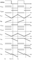
- Mode I The MOS tube of the odd-numbered transformer is turned on, and the even-numbered transformer is automatically demagnetized based on the flyback conversion, and the equalization between the odd-numbered and even-numbered modules is realized; and the equalization between the odd-numbered modules and the modules is realized based on the forward transform.
- Mode II The MOS tube of the odd-numbered transformer remains conductive, and the balance between the odd-numbered modules and the modules is still realized based on the forward conversion, and the preconditions for the degaussing of the odd-numbered transformers are provided.
- Mode III The MOS tube of the even-numbered transformer is turned on, the degaussing is performed to automatically degauss the transformer, and the equalization between the odd and even modules is realized; the equalization between the even modules and the modules is realized based on the forward conversion.
- Mode IV The MOS transistor of the even transformer remains on, and the equalization within the even module and between the modules is still achieved based on the forward conversion.
- a modular method for a battery pack equalizer based on a multi-winding transformer includes 8 battery cells including 2 battery modules, a microcontroller, two multi-winding transformers, and 8 MOS tubes. .
- the multi-winding transformer includes four primary windings and one secondary winding;
- a battery cell is connected to the drain of a MOS transistor, the source of the MOS transistor is connected to one end of a primary winding of a transformer, and the other end of the winding is connected to the negative pole of the battery cell to form a current loop;
- the secondary windings of the multi-winding transformer are connected in parallel;
- the multi-winding transformer is divided into two groups, and the odd-numbered and even-numbered transformer secondary windings have opposite opposite ends;
- the microcontroller includes two pulse width modulated PWM signal outputs;
- the pulse width modulation PWM signal output terminal sends a pair of state complementary high frequency PWM signals, namely PWM+ and PWM-;
- the pulse width modulation PWM+ signal is connected to the gate of the MOS tube corresponding to the primary winding of the odd transformer through a driving circuit for generating a control driving signal of the group of MOS tube switches;
- the pulse width modulation PWM-signal is connected to the gate of the MOS transistor corresponding to the primary winding of the even transformer through a driving circuit for generating a control driving signal of the group of MOS transistor switches.
- Figure 5 is a graph showing the relationship between equalization efficiency and equalization power of the present invention. It can be seen that the present invention has a higher equalization efficiency over a wide load range, with a maximum efficiency of 89.4%.
- Figure 6 shows an equilibrium experiment diagram of the present invention.
- the initial cell voltages were 3.528V, 3.524V, 3.429V, 3.165V, 3.652V, 3.616V, 3.621V, and 3.383V, and the maximum initial voltage difference was 0.487V. After 5800s, all cell voltages converge to near 3.515V, with a maximum voltage difference of 3mV.
- the experimental results show that the equalization circuit of the invention can obtain the simultaneous equalization of any battery cell to any battery cell, and has a fast equalization speed and high equalization efficiency.
Landscapes
- Engineering & Computer Science (AREA)
- Power Engineering (AREA)
- Charge And Discharge Circuits For Batteries Or The Like (AREA)
- Secondary Cells (AREA)
- Battery Mounting, Suspending (AREA)
Abstract
Description
Claims (10)
- 一种基于多绕组变压器的电池组均衡器模块化系统,其特征是:包括多个电池模块、微控制器、多个多绕组变压器和多个MOS管,其中,每个电池模块包括若干个电池单体,每个电池模块对应配置有一个多绕组变压器;所述多绕组变压器包括y个原边绕组和一个副边绕组,每个电池单体连接于一个MOS管的漏极,MOS管的源极连接于一个多绕组变压器的一个原边绕组的一端,绕组的另外一端连接于该电池单体的负极,形成一个电流回路,微控制器输出两路互补的PWM信号,分别驱动具有相反的同名端的原边绕组对应的MOS管。
- 如权利要求1所述的一种基于多绕组变压器的电池组均衡器模块化系统,其特征是:共有x*y节电池单体,其中,x为电池模块数,y为一个模块包括的电池单体数。
- 如权利要求1所述的一种基于多绕组变压器的电池组均衡器模块化系统,其特征是:相邻的多绕组变压器副边的反向并联连接。
- 如权利要求1所述的一种基于多绕组变压器的电池组均衡器模块化系统,其特征是:所述多绕组变压器的副边绕组相并联。
- 如权利要求1所述的一种基于多绕组变压器的电池组均衡器模块化系统,其特征是:所述多绕组变压器分为两组,奇数和偶数变压器副边绕组具有相反的同名端。
- 如权利要求5所述的一种基于多绕组变压器的电池组均衡器模块化系统,其特征是:所述脉冲宽度调制PWM信号输出端发送一对状态互补的高频PWM信号,即PWM+和PWM-;所述脉冲宽度调制PWM+信号通过驱动电路连接于奇数变压器原边绕组对应的MOS管的栅极,用于产生该组MOS管开关的控制驱动信号;所述脉冲宽度调制PWM-信号通过驱动电路连接于偶数变压器原边绕组对应的MOS管的栅极,用于产生该组MOS管开关的控制驱动信号。
- 一种基于多绕组变压器的电池组均衡器模块化方法,其特征是:微控制器的脉冲宽度调制PWM信号输出端发送一对状态互补的PWM信号分别控制多绕组变压器中奇数和偶数变压器对应的MOS管交替导通,基于正激变换电池模块内和奇/偶数电池模块间的均衡或基于反激变换实现奇数和偶数电池模块间的均衡以及变压器的自动消磁。
- 如权利要求7所述的一种基于多绕组变压器的电池组均衡器模块化方法,其特征是:控制过程共包括四种工作模式:(1)当奇数变压器的MOS管导通,基于反激变换对偶数变压器进行自动消磁,并实现奇数和偶数模块间的均衡,基于正激变换实现奇数模块内和模块间的均衡;(2)奇数变压器的MOS管保持导通,基于正激变换实现奇数模块内和模块间的均衡,并对奇数变压器的消磁提供前提条件;(3)偶数变压器的MOS管导通,基于反激变换对寄数变压器进行自动消磁,并实现奇数和偶数模块间的均衡;基于正激变换实现偶数模块内和模块间的均衡。(4)偶数变压器的MOS管保持导通,仍然基于正激变换实现偶数模块内和模块间的均衡。
- 如权利要求8所述的一种基于多绕组变压器的电池组均衡器模块化方法,其特征是:经过这四个模式的不断交替,基于正激变换实现了模块内和奇/偶数模块间的均衡;基于反激变换,实现奇数和偶数模块之间的均衡,从而获得整个电池组的全局均衡,同时对所有变压器起到了自动消磁作用。
- 如权利要求7所述的一种基于多绕组变压器的电池组均衡器模块化方法,其特征是:控制方法施加于电池组的充电、放电或静止状态。
Priority Applications (1)
| Application Number | Priority Date | Filing Date | Title |
|---|---|---|---|
| US16/492,836 US20200169097A1 (en) | 2017-03-16 | 2017-10-19 | Modularization system and method for battery equalizers based on multi- winding transformers |
Applications Claiming Priority (2)
| Application Number | Priority Date | Filing Date | Title |
|---|---|---|---|
| CN201710157515.6 | 2017-03-16 | ||
| CN201710157515.6A CN106787021B (zh) | 2017-03-16 | 2017-03-16 | 一种基于多绕组变压器的电池组均衡器模块化系统及方法 |
Publications (1)
| Publication Number | Publication Date |
|---|---|
| WO2018166205A1 true WO2018166205A1 (zh) | 2018-09-20 |
Family
ID=58966167
Family Applications (1)
| Application Number | Title | Priority Date | Filing Date |
|---|---|---|---|
| PCT/CN2017/106903 Ceased WO2018166205A1 (zh) | 2017-03-16 | 2017-10-19 | 一种基于多绕组变压器的电池组均衡器模块化系统及方法 |
Country Status (3)
| Country | Link |
|---|---|
| US (1) | US20200169097A1 (zh) |
| CN (1) | CN106787021B (zh) |
| WO (1) | WO2018166205A1 (zh) |
Cited By (4)
| Publication number | Priority date | Publication date | Assignee | Title |
|---|---|---|---|---|
| CN109672246A (zh) * | 2019-01-16 | 2019-04-23 | 西南交通大学 | 基于Buck_Boost单元的反激式多路均衡电路及其控制方法 |
| US11329567B2 (en) | 2017-10-27 | 2022-05-10 | Appulse Power Inc. | Merged voltage-divider forward converter |
| CN114530915A (zh) * | 2022-03-15 | 2022-05-24 | 盐城工学院 | 基于双向开关控制的级联整流式锂电池均衡器 |
| US12057815B2 (en) | 2021-07-26 | 2024-08-06 | Eldora Productions | Interchangeable cartridge audio preamplifier for microphone, and kit comprising the same |
Families Citing this family (17)
| Publication number | Priority date | Publication date | Assignee | Title |
|---|---|---|---|---|
| CN106787021B (zh) * | 2017-03-16 | 2023-11-17 | 山东大学 | 一种基于多绕组变压器的电池组均衡器模块化系统及方法 |
| CN107294174B (zh) * | 2017-07-25 | 2020-11-17 | 西安交通大学 | 一种电池单体与电池组间均衡电路结构与方法 |
| CN107359670B (zh) * | 2017-08-21 | 2020-06-09 | 上海空间电源研究所 | 一种空间高压蓄电池组双向均衡电路及其双向均衡方法 |
| CN107565183B (zh) * | 2017-09-07 | 2020-05-22 | 山东大学 | 面向全生命周期应用的模块化分布式电池管理系统及方法 |
| CN107785957A (zh) * | 2017-10-20 | 2018-03-09 | 开沃新能源汽车集团有限公司 | 基于正激和反激变换的电池均衡电路及实现方法 |
| CN107834655A (zh) * | 2017-11-29 | 2018-03-23 | 山东大学 | 一种基于多绕组变压器的自动的电池均衡电路及实现方法 |
| CN108054468A (zh) * | 2017-12-07 | 2018-05-18 | 山东大学 | 电动汽车动力电池低温交流加热基本拓扑电路及其应用 |
| CN108054469A (zh) * | 2017-12-07 | 2018-05-18 | 山东大学 | 电动汽车动力电池内外部联合加热-均衡一体化拓扑及方法 |
| CN109066846B (zh) * | 2018-08-01 | 2020-07-28 | 西安交通大学 | 一种模块化电池间均衡电路结构与方法 |
| US12308673B2 (en) * | 2019-03-21 | 2025-05-20 | Hefei Gotion High-Tech Power Energy Co., Ltd. | Active equalizer circuit, battery management system, and power supply system |
| CN110707780B (zh) * | 2019-10-29 | 2022-08-23 | 温州大学 | 一种基于变压器的交错式电池均衡电路结构 |
| CN112290619B (zh) * | 2020-10-16 | 2023-03-28 | 中南大学 | 一种带有自动功率限制功能的电池均衡器 |
| CN112688375B (zh) * | 2020-12-03 | 2022-12-16 | 华南理工大学 | 基于多绕组变压器的均衡输出系统 |
| CN112491289A (zh) * | 2020-12-30 | 2021-03-12 | 深圳市永联科技股份有限公司 | 一种新型的多绕组变压器均衡系统拓扑 |
| CN112994142B (zh) * | 2021-01-25 | 2023-09-01 | 山东大学 | 一种电池均衡-交流加热一体化拓扑及控制方法 |
| US12283831B2 (en) * | 2021-03-01 | 2025-04-22 | Volvo Car Corporation | On-board charger and DC-DC converter architecture for balancing of voltages or currents between batteries in electric vehicle battery systems |
| CN114914996B (zh) * | 2022-07-13 | 2022-10-25 | 宁波均胜新能源研究院有限公司 | 电池管理系统及其控制方法 |
Citations (4)
| Publication number | Priority date | Publication date | Assignee | Title |
|---|---|---|---|---|
| CN103036256A (zh) * | 2011-10-08 | 2013-04-10 | 上海锂曜能源科技有限公司 | 变压器扫描链式蓄电池组均衡电路及方法 |
| CN204258367U (zh) * | 2014-11-28 | 2015-04-08 | 杭州协能科技有限公司 | 基于外部控制反激电路的电池组双向主动均衡电路 |
| CN106787021A (zh) * | 2017-03-16 | 2017-05-31 | 山东大学 | 一种基于多绕组变压器的电池组均衡器模块化系统及方法 |
| CN206517117U (zh) * | 2017-03-16 | 2017-09-22 | 山东大学 | 一种基于多绕组变压器的电池组均衡器模块化系统 |
Family Cites Families (5)
| Publication number | Priority date | Publication date | Assignee | Title |
|---|---|---|---|---|
| JP3848635B2 (ja) * | 2003-04-23 | 2006-11-22 | 富士重工業株式会社 | 蓄電素子の電圧均等化装置 |
| EP2587614A2 (en) * | 2011-08-31 | 2013-05-01 | Sony Corporation | Electric storage apparatus, electronic device, electric vehicle, and electric power system |
| KR20140012786A (ko) * | 2012-07-23 | 2014-02-04 | 김래영 | 배터리 밸런싱 제어신호 발생회로 |
| CN103532197B (zh) * | 2013-10-24 | 2016-02-24 | 山东大学 | 基于升压变换和软开关的动力电池组均衡电路及实现方法 |
| CN104377778B (zh) * | 2014-11-26 | 2016-09-07 | 山东大学 | 基于LCL谐振变换的Adjacent-Cell-to-Cell均衡电路及实现方法 |
-
2017
- 2017-03-16 CN CN201710157515.6A patent/CN106787021B/zh active Active
- 2017-10-19 WO PCT/CN2017/106903 patent/WO2018166205A1/zh not_active Ceased
- 2017-10-19 US US16/492,836 patent/US20200169097A1/en not_active Abandoned
Patent Citations (4)
| Publication number | Priority date | Publication date | Assignee | Title |
|---|---|---|---|---|
| CN103036256A (zh) * | 2011-10-08 | 2013-04-10 | 上海锂曜能源科技有限公司 | 变压器扫描链式蓄电池组均衡电路及方法 |
| CN204258367U (zh) * | 2014-11-28 | 2015-04-08 | 杭州协能科技有限公司 | 基于外部控制反激电路的电池组双向主动均衡电路 |
| CN106787021A (zh) * | 2017-03-16 | 2017-05-31 | 山东大学 | 一种基于多绕组变压器的电池组均衡器模块化系统及方法 |
| CN206517117U (zh) * | 2017-03-16 | 2017-09-22 | 山东大学 | 一种基于多绕组变压器的电池组均衡器模块化系统 |
Non-Patent Citations (1)
| Title |
|---|
| SHANG, Y.L. ET AL.: "An Automatic Equalizer Based on Forward-Flyback Converter for Series-Connected Battery Strings, IEEE Transactions on Industrial Electronics", IEEE TRANSACTIONS ON INDUSTRIAL ELECTRONICS, vol. 64, no. 7, 24 February 2017 (2017-02-24), XP055538963 * |
Cited By (6)
| Publication number | Priority date | Publication date | Assignee | Title |
|---|---|---|---|---|
| US11329567B2 (en) | 2017-10-27 | 2022-05-10 | Appulse Power Inc. | Merged voltage-divider forward converter |
| US11979091B2 (en) | 2017-10-27 | 2024-05-07 | Appulse Power Inc. | Merged voltage-divider forward converter |
| CN109672246A (zh) * | 2019-01-16 | 2019-04-23 | 西南交通大学 | 基于Buck_Boost单元的反激式多路均衡电路及其控制方法 |
| CN109672246B (zh) * | 2019-01-16 | 2024-01-19 | 西南交通大学 | 基于Buck_Boost单元的反激式多路均衡电路及其控制方法 |
| US12057815B2 (en) | 2021-07-26 | 2024-08-06 | Eldora Productions | Interchangeable cartridge audio preamplifier for microphone, and kit comprising the same |
| CN114530915A (zh) * | 2022-03-15 | 2022-05-24 | 盐城工学院 | 基于双向开关控制的级联整流式锂电池均衡器 |
Also Published As
| Publication number | Publication date |
|---|---|
| CN106787021B (zh) | 2023-11-17 |
| CN106787021A (zh) | 2017-05-31 |
| US20200169097A1 (en) | 2020-05-28 |
Similar Documents
| Publication | Publication Date | Title |
|---|---|---|
| WO2018166205A1 (zh) | 一种基于多绕组变压器的电池组均衡器模块化系统及方法 | |
| CN112290619B (zh) | 一种带有自动功率限制功能的电池均衡器 | |
| CN107785957A (zh) | 基于正激和反激变换的电池均衡电路及实现方法 | |
| CN206379755U (zh) | 一种储能电池组均衡装置 | |
| CN102651563A (zh) | 电池能量平衡电路 | |
| CN105391130B (zh) | 基于多相交错变换器的电池均衡电路及其控制方法 | |
| CN112688391A (zh) | 基于对称cllc直流变换器的锂离子电池均衡电路 | |
| Moghaddam et al. | Multi-winding equalization technique for lithium ion batteries for electrical vehicles | |
| CN106532802B (zh) | 串联储能体四单体直接均衡装置及方法 | |
| CN112202218B (zh) | 基于双极性t型双谐振开关电容变换器的均衡电路及控制方法 | |
| CN105871022B (zh) | 一种电池组主动均衡电路及方法 | |
| Shang et al. | An automatic battery equalizer based on forward and flyback conversion for series-connected battery strings | |
| CN116094087A (zh) | 一种串联电池组主动均衡电路 | |
| CN109617161B (zh) | 一种准谐振交错开关电容电池均衡电路及其控制方法 | |
| CN109066846A (zh) | 一种模块化电池间均衡电路结构与方法 | |
| CN106961140A (zh) | 基于互感变压器的梯形结构储能电源均衡系统 | |
| CN204144970U (zh) | Pwm信号生成装置及电池组电量主动均衡控制系统 | |
| CN107800292B (zh) | 串联能量存储装置的均压电路及含有该电路的均压系统 | |
| CN110707780B (zh) | 一种基于变压器的交错式电池均衡电路结构 | |
| CN105811529A (zh) | 一种混合均衡拓扑结构的均衡电路 | |
| CN108598604A (zh) | 反激模式串联储能均衡电路 | |
| CN206517117U (zh) | 一种基于多绕组变压器的电池组均衡器模块化系统 | |
| CN114793000A (zh) | 一种基于半桥cllc直流变换器的锂离子电池均衡电路 | |
| CN115800449A (zh) | 基于改进Buck-Boost均衡电路的电池组充电控制方法 | |
| CN107834655A (zh) | 一种基于多绕组变压器的自动的电池均衡电路及实现方法 |
Legal Events
| Date | Code | Title | Description |
|---|---|---|---|
| 121 | Ep: the epo has been informed by wipo that ep was designated in this application |
Ref document number: 17900713 Country of ref document: EP Kind code of ref document: A1 |
|
| NENP | Non-entry into the national phase |
Ref country code: DE |
|
| 122 | Ep: pct application non-entry in european phase |
Ref document number: 17900713 Country of ref document: EP Kind code of ref document: A1 |
|
| 122 | Ep: pct application non-entry in european phase |
Ref document number: 17900713 Country of ref document: EP Kind code of ref document: A1 |
|
| 32PN | Ep: public notification in the ep bulletin as address of the adressee cannot be established |
Free format text: NOTING OF LOSS OF RIGHTS PURSUANT TO RULE 112(1) EPC (EPO FORM 1205A DATED 05/03/2020) |
|
| 122 | Ep: pct application non-entry in european phase |
Ref document number: 17900713 Country of ref document: EP Kind code of ref document: A1 |