WO2018164032A1 - 車両用の熱管理システム及びその制御方法 - Google Patents
車両用の熱管理システム及びその制御方法 Download PDFInfo
- Publication number
- WO2018164032A1 WO2018164032A1 PCT/JP2018/008235 JP2018008235W WO2018164032A1 WO 2018164032 A1 WO2018164032 A1 WO 2018164032A1 JP 2018008235 W JP2018008235 W JP 2018008235W WO 2018164032 A1 WO2018164032 A1 WO 2018164032A1
- Authority
- WO
- WIPO (PCT)
- Prior art keywords
- refrigerant
- heat exchanger
- heat
- management system
- heat exchange
- Prior art date
- Legal status (The legal status is an assumption and is not a legal conclusion. Google has not performed a legal analysis and makes no representation as to the accuracy of the status listed.)
- Ceased
Links
Images



Classifications
-
- B—PERFORMING OPERATIONS; TRANSPORTING
- B60—VEHICLES IN GENERAL
- B60L—PROPULSION OF ELECTRICALLY-PROPELLED VEHICLES; SUPPLYING ELECTRIC POWER FOR AUXILIARY EQUIPMENT OF ELECTRICALLY-PROPELLED VEHICLES; ELECTRODYNAMIC BRAKE SYSTEMS FOR VEHICLES IN GENERAL; MAGNETIC SUSPENSION OR LEVITATION FOR VEHICLES; MONITORING OPERATING VARIABLES OF ELECTRICALLY-PROPELLED VEHICLES; ELECTRIC SAFETY DEVICES FOR ELECTRICALLY-PROPELLED VEHICLES
- B60L3/00—Electric devices on electrically-propelled vehicles for safety purposes; Monitoring operating variables, e.g. speed, deceleration or energy consumption
-
- B—PERFORMING OPERATIONS; TRANSPORTING
- B60—VEHICLES IN GENERAL
- B60H—ARRANGEMENTS OF HEATING, COOLING, VENTILATING OR OTHER AIR-TREATING DEVICES SPECIALLY ADAPTED FOR PASSENGER OR GOODS SPACES OF VEHICLES
- B60H1/00—Heating, cooling or ventilating devices
- B60H1/22—Heating, cooling or ventilating devices the heat source being other than the propulsion plant
-
- B—PERFORMING OPERATIONS; TRANSPORTING
- B60—VEHICLES IN GENERAL
- B60H—ARRANGEMENTS OF HEATING, COOLING, VENTILATING OR OTHER AIR-TREATING DEVICES SPECIALLY ADAPTED FOR PASSENGER OR GOODS SPACES OF VEHICLES
- B60H1/00—Heating, cooling or ventilating devices
- B60H1/32—Cooling devices
-
- F—MECHANICAL ENGINEERING; LIGHTING; HEATING; WEAPONS; BLASTING
- F25—REFRIGERATION OR COOLING; COMBINED HEATING AND REFRIGERATION SYSTEMS; HEAT PUMP SYSTEMS; MANUFACTURE OR STORAGE OF ICE; LIQUEFACTION SOLIDIFICATION OF GASES
- F25B—REFRIGERATION MACHINES, PLANTS OR SYSTEMS; COMBINED HEATING AND REFRIGERATION SYSTEMS; HEAT PUMP SYSTEMS
- F25B1/00—Compression machines, plants or systems with non-reversible cycle
-
- B—PERFORMING OPERATIONS; TRANSPORTING
- B60—VEHICLES IN GENERAL
- B60K—ARRANGEMENT OR MOUNTING OF PROPULSION UNITS OR OF TRANSMISSIONS IN VEHICLES; ARRANGEMENT OR MOUNTING OF PLURAL DIVERSE PRIME-MOVERS IN VEHICLES; AUXILIARY DRIVES FOR VEHICLES; INSTRUMENTATION OR DASHBOARDS FOR VEHICLES; ARRANGEMENTS IN CONNECTION WITH COOLING, AIR INTAKE, GAS EXHAUST OR FUEL SUPPLY OF PROPULSION UNITS IN VEHICLES
- B60K6/00—Arrangement or mounting of plural diverse prime-movers for mutual or common propulsion, e.g. hybrid propulsion systems comprising electric motors and internal combustion engines
- B60K6/20—Arrangement or mounting of plural diverse prime-movers for mutual or common propulsion, e.g. hybrid propulsion systems comprising electric motors and internal combustion engines the prime-movers consisting of electric motors and internal combustion engines, e.g. HEVs
- B60K6/22—Arrangement or mounting of plural diverse prime-movers for mutual or common propulsion, e.g. hybrid propulsion systems comprising electric motors and internal combustion engines the prime-movers consisting of electric motors and internal combustion engines, e.g. HEVs characterised by apparatus, components or means specially adapted for HEVs
-
- B—PERFORMING OPERATIONS; TRANSPORTING
- B60—VEHICLES IN GENERAL
- B60W—CONJOINT CONTROL OF VEHICLE SUB-UNITS OF DIFFERENT TYPE OR DIFFERENT FUNCTION; CONTROL SYSTEMS SPECIALLY ADAPTED FOR HYBRID VEHICLES; ROAD VEHICLE DRIVE CONTROL SYSTEMS FOR PURPOSES NOT RELATED TO THE CONTROL OF A PARTICULAR SUB-UNIT
- B60W10/00—Conjoint control of vehicle sub-units of different type or different function
- B60W10/30—Conjoint control of vehicle sub-units of different type or different function including control of auxiliary equipment, e.g. air-conditioning compressors or oil pumps
-
- B—PERFORMING OPERATIONS; TRANSPORTING
- B60—VEHICLES IN GENERAL
- B60W—CONJOINT CONTROL OF VEHICLE SUB-UNITS OF DIFFERENT TYPE OR DIFFERENT FUNCTION; CONTROL SYSTEMS SPECIALLY ADAPTED FOR HYBRID VEHICLES; ROAD VEHICLE DRIVE CONTROL SYSTEMS FOR PURPOSES NOT RELATED TO THE CONTROL OF A PARTICULAR SUB-UNIT
- B60W20/00—Control systems specially adapted for hybrid vehicles
Definitions
- the present disclosure relates to a thermal management system for a vehicle and a control method thereof.
- a vehicular heat management system including a water condenser that replaces see, for example, Patent Document 1.
- a water condenser that replaces
- the liquid loop is configured to absorb heat (heat absorption) from the heating element and to dissipate heat by the radiator. For this reason, there may be a case where the temperature of the liquid heat medium flowing through the WCDS is higher than the gas-liquid saturation temperature of the refrigerant flowing through the refrigerant loop. That is, even if the refrigerant loop radiates heat with WCDS, there is a possibility that the refrigerant reaches the expansion device without being condensed and appropriate adiabatic expansion cannot be performed.
- This disclosure is intended to provide a vehicle thermal management system and a control method thereof that can obtain a condensed refrigerant even when the refrigerant cannot be sufficiently dissipated by WCDS and is not condensed.
- the vehicle thermal management system includes a first loop that cools the heating element or the engine by circulating a liquid heat medium in the heating element or the engine, and a second that circulates the refrigerant in the cooling heat exchanger.
- a vehicle heat management system comprising: a loop; and a refrigerant condenser that exchanges heat between the liquid heat medium flowing through the first loop and the refrigerant flowing through the second loop, wherein the second loop is A refrigerant, a refrigerant condenser, an expansion device, and a cooling heat exchanger in order in the flow direction of the refrigerant, and the refrigerant guided from the refrigerant condenser to the expansion device is An internal heat exchanger that performs heat exchange of the refrigerant between the flowing first heat exchange unit and the second heat exchange unit through which the refrigerant guided from the cooling heat exchanger flows to the compressor.
- the second loop has a liquid tank between the internal heat exchanger and the expansion device.
- the degree of freedom in designing the refrigerant condenser can be increased.
- a liquid refrigerant with less bubbles can be supplied to the expansion device, and the refrigeration cycle can be operated more stably.
- the second loop has an accumulator between the internal heat exchanger and the compressor. Liquid refrigerant can be prevented from being sucked into the compressor and gas refrigerant can be reliably supplied, and the refrigeration cycle can be operated more stably.
- the first loop includes a form having no heating heat exchanger.
- the second loop does not have a refrigerant radiator that exchanges heat between the refrigerant and the outside air of the vehicle.
- the second loop includes ⁇ i> a first bypass that bypasses the first heat exchange unit and guides the refrigerant from the refrigerant condenser to the expansion device.
- Internal heat exchange having either or both of a path or ⁇ ii> a second bypass circuit that bypasses the second heat exchange section and guides the refrigerant from the cooling heat exchanger to the compressor It is preferable to include a bypass circuit and a ratio adjusting unit that changes a ratio of the refrigerant flowing through the internal heat exchanger or the internal heat exchanger bypass.
- the internal heat exchanger can be bypassed to reduce the passage resistance in the internal heat exchanger.
- the suction pressure by the compressor can be further reduced, and the power of the compressor can be further reduced.
- the second loop includes ⁇ i> a first bypass that bypasses the first heat exchange unit and guides the refrigerant from the refrigerant condenser to the expansion device.
- Internal heat exchange having either or both of a path or ⁇ ii> a second bypass circuit that bypasses the second heat exchange section and guides the refrigerant from the cooling heat exchanger to the compressor A bypass path, a refrigerant flow path having a plurality of flow path patterns capable of changing the heat exchange amount of the internal heat exchanger in two or more stages, and a heat exchange amount adjusting means for changing the flow path pattern. It is preferable.
- the degree of refrigerant condensation in the internal heat exchanger can be adjusted according to the degree of refrigerant condensation in the refrigerant condenser, and a balance between refrigerant condensation and passage resistance reduction can be achieved.
- the flow path pattern includes a form including a short flow path for passing the refrigerant through a part of the first heat exchange section or the second heat exchange section.
- the internal heat exchanger includes a plurality of heat exchange units in which the first heat exchange unit and the second heat exchange unit make a pair, and the heat exchange The units are each connected in parallel to the internal heat exchanger bypass, and the flow path pattern includes a form including a branch flow path that distributes the refrigerant to at least one of the heat exchange units. To do.
- the vehicle thermal management system control method according to the present invention is configured to distribute the entire amount of the refrigerant to the internal heat exchanger detour when the wetness of the refrigerant flowing out of the refrigerant condenser is 100%.
- the control method for a vehicle thermal management system is characterized in that when the wetness of the refrigerant flowing out of the refrigerant condenser is 0%, the entire amount of the refrigerant is circulated to the internal heat exchanger.
- the vehicle thermal management system control method includes: when the wetness of the refrigerant that has flowed out of the refrigerant condenser is greater than 0% and less than 100%, depending on the wetness of the refrigerant, The effective area for heat exchange of the heat exchanger is changed.
- a vehicle thermal management system and a control method thereof that can obtain a condensed refrigerant even when the refrigerant cannot be sufficiently dissipated by WCDS and is not condensed.
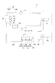
- FIG. 1 is a system diagram illustrating a first example of a vehicle thermal management system according to an embodiment. It is a system diagram which shows the 2nd example of the thermal management system for vehicles which concerns on this embodiment. It is a system diagram which shows the 3rd example of the thermal management system for vehicles which concerns on this embodiment. It is a system diagram which shows the 4th example of the thermal management system for vehicles which concerns on this embodiment.
- FIG. 1 is a system diagram showing a first example of a vehicle thermal management system according to the present embodiment.
- the vehicle thermal management system 1 of the first example cools the heating elements 12, 13, 14 or the engine (not shown) by circulating a liquid heat medium in the heating elements 12, 13, 14 or the engine (not shown).
- Refrigerant condensation that exchanges heat between the first loop 10, the second loop 20 that circulates the refrigerant in the cooling heat exchanger 23, and the liquid heat medium that flows through the first loop 10 and the refrigerant that flows through the second loop 20.
- the second loop 20 includes a compressor 21, a refrigerant condenser 30, an expansion device 22, and a cooling heat exchanger 23 in the refrigerant flow direction.
- the first loop 10 is, for example, a low-temperature system loop (illustrated in FIG. 1) that cools the heating elements 12, 13, and 14 by circulating a liquid heat medium through heating elements such as the DC / DC converter 12, the inverter 13, and the motor 14. ) Or a high-temperature system loop (not shown) that cools the engine by circulating a liquid heat medium in the engine (not shown).
- the liquid heat medium is, for example, water or antifreeze.
- the first loop 10 is more preferably a low temperature system loop. Taking the case where the first loop 10 is a low-temperature loop as an example, the circulation of the liquid heat medium in the first loop 10 will be described.
- the first loop 10 includes a cooling flow path 10A for circulating the liquid heat medium in the order of the first water pump 11, the DC / DC converter 12, the inverter 13, the motor 14, and the radiator 15, and the liquid heat medium for the second water pump. 16, a radiator 15, a refrigerant condenser 30, and a heat exchanger 17 for heating are circulated in this order.
- the liquid heat medium cools the heating elements such as the DC / DC converter 12, the inverter 13, and the motor 14, and is sent to the radiator 15.
- the DC / DC converter 12 steps down the power supplied from a battery (not shown) and outputs it to a power supply system (for example, a sub-battery) different from the power supply system of the drive system such as the inverter 13 and the motor 14.
- the inverter 13 converts DC power of a battery (not shown) into AC power according to the required driving force of the vehicle and supplies the AC power to the motor 14.
- the motor 14 is an electric motor for driving the vehicle, and receives power supplied from a battery (not shown) to drive the vehicle.
- the radiator 15 is a heat exchanger that exchanges heat between the liquid heat medium and the air passing through the radiator 15, and releases the heat of the liquid heat medium to the air passing through the radiator 15.
- the liquid heat medium cooled by the radiator 15 is sent to the heating elements 12, 13, and 14 again.
- the liquid heat medium cooled by the radiator 15 is sent to the refrigerant condenser 30.
- the refrigerant condenser 30 heat exchange is performed between the liquid heat medium and the refrigerant in the second loop 20, and the liquid heat medium absorbs the heat of the refrigerant.
- the liquid heat medium warmed by the refrigerant condenser 30 is sent to the heat exchanger 17 for heating.
- heat exchanger 17 for heating heat exchange is performed between the liquid heat medium and the blown air, and the heat of the liquid heat medium is released to the blown air.
- the liquid heat medium cooled by the heating heat exchanger 17 is sent to the radiator 15 again.
- the blown air warmed by the heating heat exchanger 17 is blown into the vehicle interior as necessary.
- the vehicle thermal management system 1 includes a form in which the first loop 10 does not include the heating heat exchanger 17.
- the liquid heat medium cooled by the radiator 15 is sent to the refrigerant condenser 30 in the heat exchange flow path 10 ⁇ / b> B.
- the liquid heat medium warmed by the refrigerant condenser 30 is sent to the radiator 15 again.
- the second loop 20 has a refrigeration cycle in which the refrigerant is circulated in the order of the compressor 21, the refrigerant condenser 30, the internal heat exchanger 40, the expansion device 22, the cooling heat exchanger 23, and the internal heat exchanger 40.
- the refrigerant is, for example, chlorofluorocarbon.
- the compressor 21 receives a driving force of a motor (not shown) driven by electric power or receives a driving force from an engine (not shown) to compress a low-temperature and low-pressure gaseous refrigerant to generate a high temperature. Use a high-pressure gaseous refrigerant.
- the refrigerant condenser 30 is also called a water condenser (WCDS), and is a heat exchanger that performs heat exchange between the liquid heat medium flowing through the first loop 10 and the refrigerant flowing through the second loop 20.
- WCDS water condenser
- the expansion device 22 decompresses and expands the high-pressure liquid refrigerant to form a low-temperature and low-pressure mist refrigerant and adjusts the flow rate of the refrigerant.
- the cooling heat exchanger 23 vaporizes the liquid refrigerant, and cools and dehumidifies the blown air passing through the cooling heat exchanger 23 with the heat of evaporation at that time.
- the internal heat exchanger 40 has a first heat exchange part 41 and a second heat exchange part 42 as refrigerant flow paths.
- the first heat exchange unit 41 and the second heat exchange unit 42 can exchange heat with each other.
- the inlet of the first heat exchange unit 41 is directly or indirectly connected to the outlet of the refrigerant condenser 30 by piping.
- the outlet of the first heat exchange unit 41 is directly or indirectly connected to the inlet of the expansion device 22 by piping.
- the liquid tank 24 is disposed between the first heat exchange unit 41 and the expansion device 22, and the outlet of the first heat exchange unit 41 is indirectly connected to the inlet of the expansion device 22 by piping. Connected form was shown.
- the inlet of the second heat exchanging unit 42 is directly or indirectly connected to the outlet of the cooling heat exchanger 23 by piping.
- the outlet of the second heat exchange unit 42 is directly or indirectly connected to the inlet of the compressor 21 by piping.
- the thermal management system 1 performs, for example, temperature adjustment of a heating element mounted on a vehicle, temperature adjustment of an engine, and temperature adjustment of a passenger compartment.
- the refrigerant condenser 30 may not sufficiently dissipate heat, and the refrigerant condenser 30 may dissipate heat at a temperature higher than the saturation temperature.
- the heat management system 1 is configured without the internal heat exchanger 40, the refrigerant may reach the expansion device 22 without being sufficiently condensed, and appropriate adiabatic expansion may not be performed.
- the internal heat exchanger 40 is arranged on the upstream side of the expansion device 22 of the second loop 20 so that the refrigerant is sufficiently condensed.
- the expansion device 22 can be reached.
- the second loop 20 preferably includes a liquid tank 24 between the internal heat exchanger 40 and the expansion device 22.
- the liquid tank 24 stores a part of the liquid refrigerant, separates the liquid refrigerant and the gaseous refrigerant, and sends only the liquid refrigerant to the expansion device 22.
- the liquid tank 24 can supply the expansion device 22 with a liquid refrigerant with less air bubbles and the refrigeration cycle can be operated more stably.
- the second loop 20 preferably has an accumulator (not shown) between the internal heat exchanger 40 and the compressor 21.
- the accumulator is a device that separates liquid refrigerant that could not be vaporized by the second heat exchanging section 42 of the internal heat exchanger 40 from gaseous refrigerant. Only the gaseous refrigerant is introduced to the suction side of the compressor 21. Send it out.
- the accumulator can prevent the liquid refrigerant from being sucked into the compressor 21, and the refrigeration cycle can be operated more stably.
- the second loop 20 preferably includes both the liquid tank 24 and an accumulator (not shown).
- the refrigeration cycle can be operated more stably.
- the vehicle thermal management system 1 includes a form in which the second loop 20 does not have a refrigerant storage component such as a liquid tank 24 or an accumulator (not shown).
- a refrigerant storage component such as a liquid tank 24 or an accumulator (not shown).
- the second loop 20 preferably does not have a refrigerant radiator (not shown) that exchanges heat between the refrigerant and the outside air of the vehicle.
- the refrigerant radiator is a heat exchanger disposed between the discharge side of the compressor 21 and the expansion device 22 in a general refrigeration cycle, and is disposed in front of the vehicle and is a high-temperature and high-pressure gaseous refrigerant. Is cooled by outside air to form a high-temperature and high-pressure liquid refrigerant.
- positions the 2nd loop 20 improves by enabling management of heat, without having a refrigerant
- FIG. 2 is a system diagram showing a second example of the thermal management system for a vehicle according to the present embodiment.
- the second loop 20 bypasses the first heat exchanging part 41 by ⁇ i> the first bypass that guides the refrigerant from the refrigerant condenser 30 to the expansion device 22.
- Internal heat having either or both of the path 51 or ⁇ ii> the second bypass circuit 52 that bypasses the second heat exchange section 42 and guides the refrigerant from the cooling heat exchanger 23 to the compressor 21.
- the first bypass 51 has one end connected directly or indirectly to the outlet of the refrigerant condenser 30 and the other end connected directly or indirectly to the inlet of the expansion device 22. As shown in FIG. 2, when the liquid tank 24 is provided, the other end of the first bypass 51 may be connected to the liquid tank 24.
- the second detour 52 has one end connected directly or indirectly to the outlet of the cooling heat exchanger 23 and the other end connected directly or indirectly to the inlet of the compressor 21.
- a configuration having both the first bypass route 51 and the second bypass route 52 (shown in FIG. 2), the first bypass route 51, and the second bypass route 52 are provided. It includes a configuration not shown (not shown), or a configuration not having the first bypass 51 and having the second bypass 52 (not shown).
- the ratio adjusting means 61 and 62 are, for example, a three-way valve, a solenoid valve, or a temperature sensitive valve.
- the ratio adjusting unit 61 changes the ratio of the refrigerant flowing through the first heat exchange unit 41 and the first detour 51.
- the ratio adjusting unit 62 changes the ratio of the refrigerant flowing through the second heat exchanging unit 42 and the second detour 52.
- the ratio adjusting means 61 and 62 are controlled by a control unit (not shown) such as an air conditioning control unit or an engine control unit.
- the control unit includes a microcomputer such as a CPU, a ROM, and a RAM.
- control unit determines the wetness of the refrigerant that has flowed out of the refrigerant condenser 30.
- a control part controls the ratio adjustment means 61 and 62 according to the determined wetness degree.
- the control unit distributes the entire amount of the refrigerant to the internal heat exchanger detours 51 and 52 and does not distribute the refrigerant to the internal heat exchanger 40.
- the refrigerant flows by bypassing the internal heat exchanger 40, and an increase in passage resistance in the internal heat exchanger 40 can be suppressed.
- the suction pressure by the compressor 21 can be further reduced, and the power of the compressor 21 can be further reduced.
- the control unit distributes the entire amount of the refrigerant to the internal heat exchanger 40 and does not distribute the refrigerant to the internal heat exchanger detours 51 and 52. Thereby, after fully condensing a refrigerant
- the control unit changes the ratio of the refrigerant flowing through the internal heat exchanger 40 or the internal heat exchanger detours 51 and 52. More specifically, the larger the proportion of the gaseous refrigerant contained in the refrigerant, the greater the proportion of the refrigerant flowing through the internal heat exchanger 40, and the smaller the proportion of the gaseous refrigerant contained in the refrigerant, the higher the internal heat.
- the ratio of the refrigerant flowing through the exchanger 40 is decreased. Thereby, after fully condensing a refrigerant
- the internal heat exchanger detours 51 and 52 are provided, so that the amount of heat dissipated in the refrigerant condenser 30 is sufficient, and the internal heat is reduced when the necessity for condensation is low. By bypassing the exchanger 40, it is possible to suppress an increase in passage resistance.
- FIG. 3 is a system diagram showing a third example of a vehicle thermal management system according to the present embodiment.
- the second loop 20 bypasses the first heat exchanging part 41 by ⁇ i> the first bypass that guides the refrigerant from the refrigerant condenser 30 to the expansion device 22.
- a second detour (not shown) that bypasses the second heat exchange section 42 and guides the refrigerant from the cooling heat exchanger 23 to the compressor 21.
- An internal heat exchanger bypass a refrigerant flow path having a plurality of flow path patterns capable of changing the heat exchange amount of the internal heat exchanger 40 in two or more stages, and a heat exchange amount adjusting means 63 for changing the flow path pattern (63A, 63B, 63C).
- the internal heat exchanger detours 51 and 52 are the same as the thermal management system 1 for the vehicle of the first example.
- FIG. 3 shows a form having only the first bypass 51 as the internal heat exchanger bypass, the present invention is not limited to this, and the first as the internal heat exchanger bypass is shown in FIG. It may be in a form having both of the detour 51 and the second detour 52, or in a form having only the second detour 52 as an internal heat exchanger detour (not shown).
- the flow path pattern includes a short flow path that allows the refrigerant to pass through a part of the first heat exchange unit 41 or the second heat exchange unit 42.
- the short flow path is a flow path in which an effective area for heat exchange with respect to the first heat exchange unit 41 or the second heat exchange unit 42 is reduced.
- the passage 51 and the first heat exchanging part 41 are connected by piping 53 and 54 at a plurality of positions, and the refrigerant is caused to flow from the middle of the first heat exchanging part 41.
- the number of connection portions between the first bypass 51 and the first heat exchange unit 41 is not particularly limited, and may be one or more, and FIG. 3 shows an example in which the number is two.
- the short flow path connects the second bypass 52 (shown in FIG. 2) and the second heat exchanging unit 42 by piping at a plurality of positions, and allows refrigerant to flow from the middle of the second heat exchanging unit 42. You may form by making it the structure which flows.
- the flow path pattern is, for example, a first pattern or refrigerant that causes the refrigerant to flow through the first heat exchange unit 41 and not flow through the first detour 51.
- a first pattern or refrigerant that causes the refrigerant to flow through the first heat exchange unit 41 and not flow through the first detour 51.
- the refrigerant flows into the first heat exchanging part 41 from the second pipe 54 on the downstream side of the refrigerant flow path from the first pipe 53.
- a fourth pattern that causes the refrigerant to flow through the first bypass 51 and not flow through the first heat exchange unit 41.
- the effective areas for heat exchange of the internal heat exchanger 40 are the first pattern, the second pattern, the third pattern, and the fourth pattern in descending order.
- the heat exchange amount adjusting means 63 is an internal heat exchanger bypass (first bypass 51 in FIG. 3) or pipes 53, 54.
- the heat exchange amount adjusting means 63 is a three-way valve
- the three-way valve is preferably disposed on the internal heat exchanger detour (the first detour 51 in FIG. 3).
- the heat exchange amount adjusting means 63 (63A, 63B, 63C) is a stop valve
- the stop valve is preferably disposed in the middle portion of the pipes 53, 54.
- the heat exchange amount adjusting means 63 (63A, 63B, 63C) is controlled by a control unit (not shown) such as an air conditioning control unit or an engine control unit.
- FIG. 4 is a system diagram showing a fourth example of the thermal management system for a vehicle according to the present embodiment.
- the vehicle thermal management system 4 of the fourth example has the same basic configuration as the vehicle thermal management system 3 of the third example, except that the flow path patterns of the refrigerant channels are different.
- the thermal management system 4 for the vehicle of the fourth example will be described.
- the configuration different from the thermal management system 3 for the vehicle of the third example will be mainly described, and the description of the common configuration will be given. Omitted.
- the internal heat exchanger detour is the same as the thermal management system 3 for the vehicle of the third example.
- a second detour 52 (shown in FIG. 2) may be provided.
- the internal heat exchanger 40 is configured such that the first heat exchange units 41a, 41b, 41c and the second heat exchange units 42a, 42b, 42c make a pair.
- a plurality of units 40A, 40B, and 40C are provided, and the heat exchange units 40A, 40B, and 40C are connected in parallel to the internal heat exchanger bypass circuit 51, respectively, and the flow path pattern includes the refrigerant as the heat exchange unit 40A It includes a branch flow path that distributes at least one of 40B and 40C.
- the heat exchange unit 40A performs heat exchange of the refrigerant between the first heat exchange unit 41a and the second heat exchange unit 42a.
- the heat exchange unit 40B performs heat exchange of the refrigerant between the first heat exchange unit 41b and the second heat exchange unit 42b.
- the heat exchange unit 40C performs heat exchange of the refrigerant between the first heat exchange unit 41c and the second heat exchange unit 42c.
- the number of heat exchange units 40A, 40B, and 40C is not particularly limited as long as it is two or more, and FIG. 4 shows an example in which the number is three.
- the flow path pattern includes a branch flow path.
- the branch flow path is a flow path for diverting the refrigerant to the first heat exchange units 41a, 41b, 41c or the second heat exchange units 42a, 42b, 42c of the heat exchange units 40A, 40B, 40C.
- the refrigerant that has flowed out of the refrigerant condenser 30 is divided into the first heat exchange units 41 a, 41 b, 41 c, merged downstream of the first heat exchange units 41 a, 41 b, 41 c, and expanded. Guided to device 22.
- the refrigerant flowing out of the cooling heat exchanger 23 is divided into the second heat exchange units 42a, 42b, 42c, and merges downstream of the second heat exchange units 42a, 42b, 42c. Led to.
- the flow path pattern is, for example, the first pattern in which the refrigerant flows through the three heat exchange units 40A, 40B, and 40C, and the refrigerant flows through the two heat exchange units 40A and 40B.
- a second pattern in which no refrigerant flows through one heat exchange unit 40C
- a third pattern in which refrigerant flows through one heat exchange unit 40A, and no refrigerant flows through two heat exchange units 40B and 40C
- a fourth pattern is included in which the refrigerant does not flow through the three heat exchange units 40A, 40B, and 40C and the refrigerant flows through the first bypass 51.
- the effective areas for heat exchange of the internal heat exchanger 40 are the first pattern, the second pattern, the third pattern, and the fourth pattern in descending order.
- the heat exchange amount adjusting means 64 (64A, 64B, 64C, 64D) is the heat exchange unit 40A, 40B, 40C or the internal heat exchanger detour (the first in FIG. 3). 1 is a valve that opens and closes the flow of refrigerant to the detour 51), for example, a stop valve.
- the heat exchange amount adjusting means 64 (64A, 64B, 64C) is provided in the pipe that leads to the first heat exchanging portions 41a, 41b, 41c.
- the heat exchange amount adjusting means 64 (64A, 64B, 64C) is controlled by a control unit (not shown) such as an air conditioning control unit or an engine control unit.
- control unit determines the wetness of the refrigerant that has flowed out of the refrigerant condenser 30.
- control unit controls the heat exchange amount adjusting means 63 and 64 according to the determined wetness.
- the control is performed in the same manner as the control of the thermal management system 2 for the vehicle in the second example. More specifically, when the wetness of the refrigerant is 100%, the flow path pattern is the fourth pattern. Moreover, when the wetness of a refrigerant
- coolant is 0%, let a flow path pattern be a 1st pattern.
- the control unit changes the effective area for heat exchange of the internal heat exchanger 40 according to the wetness of the refrigerant. More specifically, the larger the proportion of the gaseous refrigerant contained in the refrigerant, the greater the effective area for heat exchange in the internal heat exchanger 40, and the smaller the proportion of the gaseous refrigerant contained in the refrigerant, The effective area for heat exchange in the internal heat exchanger 40 is reduced.
- the flow path pattern is the second pattern
- the flow path pattern is the third pattern.
- the flow rate of the refrigerant flowing through the internal heat exchanger 40 can be adjusted according to the degree of refrigerant condensation in the refrigerant condenser 30, and the increase in passage resistance in the internal heat exchanger 40 can be minimized. Can do. As a result, the suction pressure by the compressor 21 can be further reduced, and the power of the compressor 21 can be further reduced.
- the internal heat exchanger detour 51 and the plurality of flow path patterns allow the internal heat exchanger system 30 to be changed depending on the degree of refrigerant condensation in the refrigerant condenser 30.
- the degree of condensation in the heat exchanger 40 can be adjusted, and a balance between refrigerant condensation and passage resistance reduction can be achieved.
- Second loop Heating element (DC / DC converter) 13 Heating element (inverter) 14 Heating element (motor) 15 Radiator 16 Second water pump 17 Heating heat exchanger 20 Second loop 21 Compressor 22 Expansion device 23 Cooling heat exchanger 24 Liquid tank 30 Refrigerant condenser (water condenser) 40 Internal heat exchangers 40A, 40B, 40C Heat exchange unit 41 1st heat exchange part 41a, 41b, 41c 1st heat exchange part 42 2nd heat exchange part 42a, 42b, 42c 2nd heat exchange part 51 Internal heat exchanger detour (first detour) 52 Internal heat exchanger detour (second detour) 53 Piping (first piping) 54 Piping (second piping) 61, 62 Ratio adjustment means 63 (63A, 63B, 63C) Heat exchange amount adjustment means 64 (64A, 64B, 64C, 64D) Heat exchange amount adjustment means
Landscapes
- Engineering & Computer Science (AREA)
- Mechanical Engineering (AREA)
- Physics & Mathematics (AREA)
- Thermal Sciences (AREA)
- Sustainable Development (AREA)
- Life Sciences & Earth Sciences (AREA)
- Sustainable Energy (AREA)
- Power Engineering (AREA)
- Transportation (AREA)
- General Engineering & Computer Science (AREA)
- Air-Conditioning For Vehicles (AREA)
- Hybrid Electric Vehicles (AREA)
- Electric Propulsion And Braking For Vehicles (AREA)
Abstract
【課題】本開示は、冷媒がWCDSで十分に放熱できず、凝縮されない場合であっても、凝縮冷媒を得ることのできる車両用の熱管理システム及びその制御方法を提供することを目的とする。 【解決手段】本発明に係る車両用の熱管理システム1は、発熱体12,13,14に液状熱媒体を循環させて発熱体を冷却する第1ループ10と、冷却用熱交換器23に冷媒を循環させる第2ループ20と、第1ループを流れる液状熱媒体と第2ループを流れる冷媒との間で熱交換を行う冷媒凝縮器30と、を備える車両用の熱管理システムであって、第2ループは、冷媒の流れ方向に、圧縮機21と、冷媒凝縮器と、膨張装置22と、冷却用熱交換器23とを順に有し、かつ、冷媒凝縮器から膨張装置に導かれる冷媒が流れる第1の熱交換部41と冷却用熱交換器から圧縮機に導かれる冷媒が流れる第2の熱交換部42との間で冷媒の熱交換を行う内部熱交換器40を有する。
Description
本開示は、車両用の熱管理システム及びその制御方法に関する。
車両に搭載されるモータ及びインバータなどの発熱体を不凍液などの液状熱媒体で冷却する液状ループと、車室内の温度を調整するための冷媒ループと、これら液状ループと冷媒ループとの間の熱を交換する水コンデンサとを備えた、車両用熱管理システムが知られている(例えば、特許文献1を参照。)。特許文献1の車両用熱管理システムでは、冷媒ループを稼働して車室内を冷却するときは、水コンデンサ(water cooled condenser、WCDS)によって高温高圧の冷媒から液状ループに放熱する。放熱された熱は、ラジエータにて車外の空気に放熱される。
特許文献1では、液状ループは、発熱体の熱を吸収(吸熱)し、ラジエータで放熱するように構成されている。このため、WCDSを通流する液状熱媒体の温度が、冷媒ループを通流する冷媒の気液飽和温度よりも高い場合が有りうる。すなわち、冷媒ループとしては、WCDSで放熱したとしても、冷媒が凝縮されないまま、膨張装置に到達し、適切な断熱膨張が行えないおそれがあった。
本開示は、冷媒がWCDSで十分に放熱できず、凝縮されない場合であっても、凝縮冷媒を得ることのできる車両用の熱管理システム及びその制御方法を提供することを目的とする。
本発明に係る車両用の熱管理システムは、発熱体又はエンジンに液状熱媒体を循環させて前記発熱体又は前記エンジンを冷却する第1ループと、冷却用熱交換器に冷媒を循環させる第2ループと、前記第1ループを流れる液状熱媒体と前記第2ループを流れる冷媒との間で熱交換を行う冷媒凝縮器と、を備える車両用の熱管理システムであって、前記第2ループは、前記冷媒の流れ方向に、圧縮機と、前記冷媒凝縮器と、膨張装置と、前記冷却用熱交換器とを順に有し、かつ、前記冷媒凝縮器から前記膨張装置に導かれる前記冷媒が流れる第1の熱交換部と前記冷却用熱交換器から前記圧縮機に導かれる前記冷媒が流れる第2の熱交換部との間で前記冷媒の熱交換を行う内部熱交換器を有することを特徴とする。
本発明に係る車両用の熱管理システムでは、前記第2ループは、前記内部熱交換器と前記膨張装置との間にリキッドタンクを有することが好ましい。冷媒凝縮器とリキッドタンクとを分離して、冷媒凝縮器の設計自由度を増すことができる。また、膨張装置に気泡の混入のより少ない液体状の冷媒を供給することができ、冷凍サイクルをより安定して稼動させることができる。
本発明に係る車両用の熱管理システムでは、前記第2ループは、前記内部熱交換器と前記圧縮機との間にアキュームレータを有することが好ましい。圧縮機に液体状の冷媒が吸入されることを防止して確実に気体状の冷媒を供給することができ、冷凍サイクルをより安定して稼動させることができる。
本発明に係る車両用の熱管理システムでは、前記第1ループは、加熱用熱交換器を有さない形態を包含する。
本発明に係る車両用の熱管理システムでは、前記第2ループは、前記冷媒と前記車両の外気との間で熱交換する冷媒放熱器を有さないことが好ましい。冷媒放熱器を有さなくとも熱の管理を可能とすることで、第2ループを配置する自由度が向上する
本発明に係る車両用の熱管理システムでは、前記第2ループは、<i>前記第1の熱交換部を迂回して、前記冷媒凝縮器から前記膨張装置に前記冷媒を導く第1の迂回路、若しくは<ii>前記第2の熱交換部を迂回して、前記冷却用熱交換器から前記圧縮機に前記冷媒を導く第2の迂回路、のいずれか一方又は両方を有する内部熱交換器迂回路と、前記内部熱交換器又は前記内部熱交換器迂回路を流れる前記冷媒の比率を変更する比率調整手段と、を有することが好ましい。冷媒凝縮器での放熱量が十分であり、内部熱交換器での凝縮の必要性が低いとき、内部熱交換器を迂回させて、内部熱交換器での通路抵抗を低減することができる。その結果、圧縮機による吸入圧力をより小さくすることができ、圧縮機の動力をより低下させることができる。
本発明に係る車両用の熱管理システムでは、前記第2ループは、<i>前記第1の熱交換部を迂回して、前記冷媒凝縮器から前記膨張装置に前記冷媒を導く第1の迂回路、若しくは<ii>前記第2の熱交換部を迂回して、前記冷却用熱交換器から前記圧縮機に前記冷媒を導く第2の迂回路、のいずれか一方又は両方を有する内部熱交換器迂回路と、前記内部熱交換器の熱交換量を2段階以上に変更可能な複数の流路パターンを有する冷媒流路と、前記流路パターンを変更する熱交換量調整手段と、を有することが好ましい。冷媒凝縮器における冷媒の凝縮の程度によって、内部熱交換器での冷媒の凝縮の程度を調整することができ、冷媒の凝縮と通路抵抗の低減とのバランスをとることができる。
本発明に係る車両用の熱管理システムでは、前記流路パターンは、前記冷媒を前記第1の熱交換部又は前記第2の熱交換部の一部分に通す短流路を含む形態を包含する。
本発明に係る車両用の熱管理システムでは、前記内部熱交換器が、前記第1の熱交換部と前記第2の熱交換部とが対をなす熱交換ユニットを複数有し、該熱交換ユニットは、それぞれ前記内部熱交換器迂回路に対して並列的に接続され、前記流路パターンは、前記冷媒を前記熱交換ユニットの少なくともいずれか一つに分配する分岐流路を含む形態を包含する。
本発明に係る車両の熱管理システムの制御方法は、前記冷媒凝縮器を流出した前記冷媒の湿り度が100%であるとき、前記冷媒の全量を前記内部熱交換器迂回路に流通させることを特徴とする。
本発明に係る車両用の熱管理システムの制御方法は、前記冷媒凝縮器を流出した前記冷媒の湿り度が0%であるとき、前記冷媒の全量を前記内部熱交換器に流通させることを特徴とする。
本発明に係る車両用の熱管理システムの制御方法は、前記冷媒凝縮器を流出した前記冷媒の湿り度が0%を超え100%未満であるとき、前記冷媒の湿り度に応じて、前記内部熱交換器の熱交換する有効面積を変更させることを特徴とする。
本開示によれば、冷媒がWCDSで十分に放熱できず、凝縮されない場合であっても、凝縮冷媒を得ることのできる車両用の熱管理システム及びその制御方法を提供することができる。
以下、添付の図面を参照して本発明の一態様を説明する。以下に説明する実施形態は本発明の実施例であり、本発明は、以下の実施形態に制限されるものではない。なお、本明細書及び図面において符号が同じ構成要素は、相互に同一のものを示すものとする。本発明の効果を奏する限り、種々の形態変更をしてもよい。
図1は、本実施形態に係る車両用の熱管理システムの第一例を示すシステム図である。第一例の車両用の熱管理システム1は、発熱体12,13,14又はエンジン(不図示)に液状熱媒体を循環させて発熱体12,13,14又はエンジン(不図示)を冷却する第1ループ10と、冷却用熱交換器23に冷媒を循環させる第2ループ20と、第1ループ10を流れる液状熱媒体と第2ループ20を流れる冷媒との間で熱交換を行う冷媒凝縮器30と、を備える車両用の熱管理システムであって、第2ループ20は、冷媒の流れ方向に、圧縮機21と、冷媒凝縮器30と、膨張装置22と、冷却用熱交換器23とを順に有し、かつ、冷媒凝縮器30から膨張装置22に導かれる冷媒が流れる第1の熱交換部41と冷却用熱交換器23から圧縮機21に導かれる冷媒が流れる第2の熱交換部42との間で冷媒の熱交換を行う内部熱交換器40を有する。
第1ループ10は、例えば、DC/DCコンバータ12、インバータ13及びモータ14などの発熱体に液状熱媒体を循環させて、発熱体12,13,14を冷却する低温系ループ(図1に図示)、又はエンジン(不図示)に液状熱媒体を循環させて、エンジンを冷却する高温系ループ(不図示)である。液状熱媒体は、例えば、水、不凍液である。本実施形態では、第1ループ10が低温系ループであることがより好ましい。第1ループ10が低温系ループである場合を例にとって、第1ループ10における液状熱媒体の循環について説明する。
第1ループ10は、液状熱媒体を、第1ウォーターポンプ11、DC/DCコンバータ12、インバータ13、モータ14、ラジエータ15の順に循環させる冷却流路10Aと、液状熱媒体を、第2ウォーターポンプ16、ラジエータ15、冷媒凝縮器30、加熱用熱交換器17の順に循環させる熱交換流路10Bとを有する。
冷却流路10Aでは、液状熱媒体がDC/DCコンバータ12、インバータ13及びモータ14などの発熱体を冷却し、ラジエータ15に送られる。DC/DCコンバータ12は、バッテリ(不図示)から供給された電力を降圧し、インバータ13、モータ14などの駆動系の電源系統とは異なる電源系統(例えばサブバッテリ)へ出力する。インバータ13は、車両の要求駆動力に応じてバッテリ(不図示)の直流電力を交流電力に変換してモータ14へと供給する。モータ14は、車両駆動用の電動モータであり、バッテリ(不図示)からの電力供給を受けて車両を駆動する。ラジエータ15は、液状熱媒体とラジエータ15を通過する空気との間で熱交換を行う熱交換器であり、液状熱媒体の熱をラジエータ15を通過する空気へ放出する。ラジエータ15で冷却された液状熱媒体は、再び発熱体12,13,14に送られる。
熱交換流路10Bでは、ラジエータ15で冷却された液状熱媒体が、冷媒凝縮器30に送られる。冷媒凝縮器30では、液状熱媒体と第2ループ20の冷媒との間で熱交換が行われ、液状熱媒体が冷媒の熱を吸収する。冷媒凝縮器30で暖められた液状熱媒体は、加熱用熱交換器17に送られる。加熱用熱交換器17では、液状熱媒体と送風空気との間で熱交換が行われ、液状熱媒体の熱を送風空気へ放出する。加熱用熱交換器17で冷却された液状熱媒体は、再びラジエータ15に送られる。また、加熱用熱交換器17で暖められた送風空気は必要に応じて車室内へ送風される。
本実施形態に係る車両用の熱管理システム1では、第1ループ10が、加熱用熱交換器17を有さない形態を包含する。第1ループ10が加熱用熱交換器17を有さない場合、熱交換流路10Bでは、ラジエータ15で冷却された液状熱媒体が、冷媒凝縮器30に送られる。冷媒凝縮器30で暖められた液状熱媒体は、再びラジエータ15に送られる。
第2ループ20は、冷媒を、圧縮機21、冷媒凝縮器30、内部熱交換器40、膨張装置22、冷却用熱交換器23、内部熱交換器40の順に循環させる冷凍サイクルを有する。冷媒は、例えば、フロンである。
圧縮機21は、電力によって駆動するモータ(図示せず)の駆動力を受けて、又はエンジン(図示せず)からの駆動力を受けて、低温低圧の気体状の冷媒を圧縮して、高温高圧の気体状の冷媒にする。
冷媒凝縮器30は、水コンデンサ(water cooled condenser、WCDS)とも呼ばれ、第1ループ10を流れる液状熱媒体と第2ループ20を流れる冷媒との間で熱交換を行う熱交換器である。
膨張装置22は、高圧の液体状の冷媒を減圧・膨張させて、低温低圧の霧状の冷媒とするとともに、冷媒の流量の調整を行う。
冷却用熱交換器23は、液体状の冷媒を気化させ、そのときの蒸発熱によって冷却用熱交換器23を通過する送風空気を冷却除湿する。
内部熱交換器40は、冷媒流路として第1の熱交換部41と第2の熱交換部42とを有する。第1の熱交換部41と第2の熱交換部42とは相互に熱交換を行うことができる。第1の熱交換部41の入口は、配管によって、冷媒凝縮器30の出口と直接的又は間接的に接続される。第1の熱交換部41の出口は、配管によって、膨張装置22の入口と直接的又は間接的に接続される。図1では、一例として、第1の熱交換部41と膨張装置22との間にリキッドタンク24が配置され、第1の熱交換部41の出口が、配管によって、膨張装置22の入口と間接的に接続される形態を示した。また、第2の熱交換部42の入口は、配管によって、冷却用熱交換器23の出口と直接的又は間接的に接続される。第2の熱交換部42の出口は、配管によって、圧縮機21の入口と直接的又は間接的に接続される。
本実施形態に係る熱管理システム1は、例えば、車両に搭載される発熱体の温度調整又はエンジンの温度調整、及び車室内の温度調整を行う。冷媒凝縮器30での冷媒の放熱が不十分で、冷媒凝縮器30で放熱後の冷媒の温度が飽和温度よりも高くなる場合がある。このような場合に、熱管理システム1において内部熱交換器40がない構成とすると、冷媒が十分に凝縮しないまま膨張装置22に到達し、適切な断熱膨張ができないおそれがある。本実施形態に係る熱管理システム1では、図1に示すように、第2ループ20の膨張装置22の上流側に内部熱交換器40を配置することで、冷媒を十分に凝縮させた状態で膨張装置22に到達させることができる。
本実施形態に係る車両用の熱管理システム1では、第2ループ20は、内部熱交換器40と膨張装置22との間にリキッドタンク24を有することが好ましい。冷媒凝縮器30とリキッドタンク24とを分離して、冷媒凝縮器30の設計自由度を増すことができる。リキッドタンク24は、液体状の冷媒の一部を貯留するとともに液体状の冷媒と気体状の冷媒とを分離して、液体状の冷媒だけを膨張装置22に送り出す。リキッドタンク24によって、膨張装置22に気泡の混入のより少ない液体状の冷媒を供給することができ、冷凍サイクルをより安定して稼動させることができる。
本実施形態に係る車両用の熱管理システム1では、第2ループ20は、内部熱交換器40と圧縮機21との間にアキュームレータ(不図示)を有することが好ましい。アキュームレータは、内部熱交換器40の第2の熱交換部42で気化しきれなかった液体状の冷媒を気体状の冷媒と分離する装置で、気体状の冷媒だけを圧縮機21の吸入側に送り出す。アキュームレータによって、圧縮機21に液体状の冷媒が吸入されることを防止でき、冷凍サイクルをより安定して稼動させることができる。
本実施形態に係る車両用の熱管理システム1では、第2ループ20が、リキッドタンク24及びアキュームレータ(不図示)の両方を有することが好ましい。冷凍サイクルをより安定して稼動させることができる。
本実施形態に係る車両用の熱管理システム1では、第2ループ20が、リキッドタンク24又はアキュームレータ(不図示)などの冷媒貯留部品を有さない形態を包含する。本実施形態では、冷媒貯留部品を有さなくとも熱の管理を可能とすることで、第2ループ20の構成部品を削減して、車両搭載性を向上することができる。
本実施形態に係る車両用の熱管理システム1では、第2ループ20は、冷媒と車両の外気との間で熱交換する冷媒放熱器(不図示)を有さないことが好ましい。冷媒放熱器は、一般的な冷凍サイクルにおいて、圧縮機21の吐出側と膨張装置22との間に配置される熱交換器であって、車両の前方に配置され、高温高圧の気体状の冷媒を外気によって冷却し、高温高圧の液体状の冷媒にする。本実施形態では、冷媒放熱器を有さなくとも熱の管理を可能とすることで、第2ループ20を配置する自由度が向上する。また、第2ループ20を車両の前方を経由させる必要が無く、第2ループ20の長さを短縮することができる。
次に、図2~図4を参照して、車両用の熱管理システム1の変形例について説明する。
図2は、本実施形態に係る車両用の熱管理システムの第二例を示すシステム図である。第二例の車両用の熱管理システム2では、第2ループ20は、<i>第1の熱交換部41を迂回して、冷媒凝縮器30から膨張装置22に冷媒を導く第1の迂回路51、若しくは<ii>第2の熱交換部42を迂回して、冷却用熱交換器23から圧縮機21に冷媒を導く第2の迂回路52、のいずれか一方又は両方を有する内部熱交換器迂回路と、内部熱交換器40又は内部熱交換器迂回路51,52を流れる冷媒の比率を変更する比率調整手段61,62と、を有することが好ましい。
第1の迂回路51は、一端が冷媒凝縮器30の出口と直接的又は間接的に接続され、他端が膨張装置22の入口と直接的又は間接的に接続される。図2に示すように、リキッドタンク24を設けるとき、第1の迂回路51の他端は、リキッドタンク24に接続されてもよい。
第2の迂回路52は、一端が冷却用熱交換器23の出口と直接的又は間接的に接続され、他端が圧縮機21の入口と直接的又は間接的に接続される。
本実施形態では、第1の迂回路51及び第2の迂回路52の両方を有する形態(図2に図示)、第1の迂回路51を有し、かつ、第2の迂回路52を有さない形態(不図示)、又は第1の迂回路51を有さず、かつ、第2の迂回路52を有する形態(不図示)を包含する。
比率調整手段61,62は、例えば、三方弁、電磁弁又は感温弁である。比率調整手段61は、第1の熱交換部41と第1の迂回路51とを流れる冷媒の比率を変更する。比率調整手段62は、第2の熱交換部42と第2の迂回路52とを流れる冷媒の比率を変更する。比率調整手段61,62は、空調制御ユニット又はエンジンコントロールユニットなどの制御部(不図示)で制御される。制御部は、CPU、ROM及びRAMなどのマイクロコンピュータを有する。
第二例の車両用の熱管理システム2の制御について説明する。まず、制御部は、冷媒凝縮器30から流出した冷媒の湿り度を判定する。次に、制御部は、判定した湿り度に応じて、比率調整手段61,62を制御する。
冷媒の湿り度が100%であるとき、冷媒凝縮器30での放熱量が十分であり、冷媒が十分に凝縮されているので、内部熱交換器40での凝縮の必要性が低い。このとき、制御部は、冷媒の全量を内部熱交換器迂回路51,52に流通させて、内部熱交換器40には冷媒を流通させない。これによって、内部熱交換器40を迂回して冷媒を流し、内部熱交換器40での通路抵抗の増加を抑えることができる。その結果、圧縮機21による吸入圧力をより小さくすることができ、圧縮機21の動力をより低下させることができる。
冷媒の湿り度が0%であるとき、冷媒凝縮器30での放熱量が不十分であり、冷媒が凝縮されていないので、内部熱交換器40で凝縮する必要がある。このとき、制御部は、冷媒の全量を内部熱交換器40に流通させて、内部熱交換器迂回路51,52には冷媒を流通させない。これによって、冷媒を内部熱交換器40で十分に凝縮させてから膨張装置22に到達させることができ、冷凍サイクルを安定して稼動させることができる。
冷媒の湿り度が0%を超え100%未満であるとき、冷媒凝縮器30での放熱量が不十分であり、冷媒が気液混合状態であるので、内部熱交換器40で凝縮する必要がある。このとき、制御部は、内部熱交換器40又は内部熱交換器迂回路51,52を流れる冷媒の比率を変更する。より具体的には、冷媒に含まれる気体状の冷媒の割合が多いほど、内部熱交換器40に流す冷媒の比率を増加させ、冷媒に含まれる気体状の冷媒の割合が少ないほど、内部熱交換器40に流す冷媒の比率を減少させる。これによって、冷媒を内部熱交換器40で十分に凝縮させてから膨張装置22に到達させることができ、冷凍サイクルを安定して稼動させることができる。また、内部熱交換器40に流通する冷媒の流量を冷媒凝縮器30における冷媒の凝縮の程度に応じて調整することができ、内部熱交換器40での通路抵抗の増加を最低限に抑えることができる。その結果、圧縮機21による吸入圧力をより小さくすることができ、圧縮機21の動力をより低下させることができる。
第二例の車両用の熱管理システム2では、内部熱交換器迂回路51,52を設けることで、冷媒凝縮器30での放熱量が十分であり、凝縮の必要性が低いときに内部熱交換器40を迂回させて、通路抵抗の増加を抑えることができる。
図3は、本実施形態に係る車両用の熱管理システムの第三例を示すシステム図である。第三例の車両用の熱管理システム3では、第2ループ20は、<i>第1の熱交換部41を迂回して、冷媒凝縮器30から膨張装置22に冷媒を導く第1の迂回路51、若しくは<ii>第2の熱交換部42を迂回して、冷却用熱交換器23から圧縮機21に冷媒を導く第2の迂回路(不図示)、のいずれか一方又は両方を有する内部熱交換器迂回路と、内部熱交換器40の熱交換量を2段階以上に変更可能な複数の流路パターンを有する冷媒流路と、流路パターンを変更する熱交換量調整手段63(63A,63B,63C)と、を有することが好ましい。
第三例の車両用の熱管理システム3では、内部熱交換器迂回路51,52は、第一例の車両用の熱管理システム1と同じである。図3では、内部熱交換器迂回路として第1の迂回路51だけを有する形態を示したが、本発明はこれに限定されず、図2に示すように内部熱交換器迂回路として第1の迂回路51及び第2の迂回路52の両方を有する形態、又は内部熱交換器迂回路として第2の迂回路52だけを有する形態で(不図示)あってもよい。
第三例の車両用の熱管理システム3では、流路パターンは、冷媒を第1の熱交換部41又は第2の熱交換部42の一部分に通す短流路を含む。短流路は、第1の熱交換部41又は第2の熱交換部42に対して熱交換する有効面積を減少させた流路であり、例えば、図3に示すように、第1の迂回路51と第1の熱交換部41とを複数の位置で配管53,54によって接続し、第1の熱交換部41の途中から冷媒を流す構成とすることで形成される。第1の迂回路51と第1の熱交換部41との接続部分の数は、特に限定されず、1個以上であればよく、図3では一例として2個である形態を示した。また、短流路は、第2の迂回路52(図2に図示)と第2の熱交換部42とを複数の位置で配管によって接続し、第2の熱交換部42の途中から冷媒を流す構成とすることで形成してもよい。
第三例の車両用の熱管理システム3では、流路パターンは、例えば、冷媒を第1の熱交換部41に流通させ、かつ、第1の迂回路51には流通させない第1パターン、冷媒を第1配管53から第1の熱交換部41に流入させる第2パターン、冷媒を第1配管53よりも冷媒流路の下流側にある第2配管54から第1の熱交換部41に流入させる第3パターン、及び冷媒を第1の迂回路51に流通させ、かつ、第1の熱交換部41には流通させない第4パターンを包含する。内部熱交換器40の熱交換する有効面積は、多い順に、第1パターン、第2パターン、第3パターン、第4パターンである。
第三例の車両用の熱管理システム3では、熱交換量調整手段63(63A,63B,63C)は、内部熱交換器迂回路(図3では第1の迂回路51)又は配管53,54への冷媒の流通を開閉する弁であることが好ましく、例えば、三方弁(図3に図示)又はストップバルブ(不図示)である。熱交換量調整手段63(63A,63B,63C)が三方弁であるとき、三方弁は、内部熱交換器迂回路(図3では第1の迂回路51)上に配置することが好ましい。また、熱交換量調整手段63(63A,63B,63C)がストップバルブであるとき、ストップバルブは、配管53,54の中間部分に配置することが好ましい。熱交換量調整手段63(63A,63B,63C)は、空調制御ユニット又はエンジンコントロールユニットなどの制御部(不図示)で制御される。
図4は、本実施形態に係る車両用の熱管理システムの第四例を示すシステム図である。第四例の車両用の熱管理システム4は、冷媒流路の流路パターンが異なる以外は、第三例の車両用の熱管理システム3と基本的な構成を同じくする。図4を参照して、第四例の車両用の熱管理システム4について説明するが、第三例の車両用の熱管理システム3と異なる構成を中心に説明し、共通する構成については説明を省略する。
第四例の車両用の熱管理システム4では、内部熱交換器迂回路は、第三例の車両用の熱管理システム3と同じである。内部熱交換器迂回路として第1の迂回路51に加えて、又は第1の迂回路51に代えて、第2の迂回路52(図2に図示)を有していてもよい。
第四例の車両用の熱管理システム4では、内部熱交換器40が、第1の熱交換部41a,41b,41cと第2の熱交換部42a,42b,42cとが対をなす熱交換ユニット40A,40B,40Cを複数有し、熱交換ユニット40A,40B,40Cは、それぞれ内部熱交換器迂回路51に対して並列的に接続され、流路パターンは、冷媒を熱交換ユニット40A,40B,40Cの少なくともいずれか一つに分配する分岐流路を含む。
熱交換ユニット40Aは、第1の熱交換部41aと第2の熱交換部42aとの間で冷媒の熱交換を行う。熱交換ユニット40Bは、第1の熱交換部41bと第2の熱交換部42bとの間で冷媒の熱交換を行う。熱交換ユニット40Cは、第1の熱交換部41cと第2の熱交換部42cとの間で冷媒の熱交換を行う。熱交換ユニット40A,40B,40Cの数は、特に限定されず、2個以上であればよく、図4では一例として3個である形態を示した。
第四例の車両用の熱管理システム4では、流路パターンは、分岐流路を含む。分岐流路は、各熱交換ユニット40A,40B,40Cの第1の熱交換部41a,41b,41c又は第2の熱交換部42a,42b,42cに冷媒を分流させる流路である。例えば、図4では、冷媒凝縮器30から流出した冷媒は各第1の熱交換部41a,41b,41cに分流して、第1の熱交換部41a,41b,41cの下流で合流し、膨張装置22に導かれる。また、冷却用熱交換器23から流出した冷媒は各第2の熱交換部42a,42b,42cに分流して、第2の熱交換部42a,42b,42cの下流で合流し、圧縮機21に導かれる。
第四例の車両用の熱管理システム4では、流路パターンは、例えば、3つの熱交換ユニット40A,40B,40Cに冷媒を流す第1パターン、2つの熱交換ユニット40A,40Bに冷媒を流し、かつ、1つの熱交換ユニット40Cには冷媒を流さない第2パターン、1つの熱交換ユニット40Aに冷媒を流し、かつ、2つの熱交換ユニット40B,40Cには冷媒を流さない第3パターン、3つの熱交換ユニット40A,40B,40Cに冷媒を流さず、かつ、第1の迂回路51に冷媒を流す第4パターンを包含する。内部熱交換器40の熱交換する有効面積は、多い順に、第1パターン、第2パターン、第3パターン、第4パターンである。
第四例の車両用の熱管理システム4では、熱交換量調整手段64(64A,64B,64C,64D)は、熱交換ユニット40A,40B,40C又は内部熱交換器迂回路(図3では第1の迂回路51)への冷媒の流通を開閉する弁であり、例えば、ストップバルブである。図4では、一例として、熱交換量調整手段64(64A,64B,64C)が第1の熱交換部41a,41b,41cに通じる配管に設けられた形態を示したが、熱交換量調整手段64(64A,64B,64C)は、第2の熱交換部42a,42b,42cに通じる配管に設けられるか、又は、第1の熱交換部41a,41b,41cに通じる配管及び第2の熱交換部42a,42b,42cに通じる配管の両方に設けられてもよい。熱交換量調整手段64(64A,64B,64C,64D)は、空調制御ユニット又はエンジンコントロールユニットなどの制御部(不図示)で制御される。
第三例、第四例の車両用の熱管理システム3,4の制御について説明する。まず、制御部は、冷媒凝縮器30から流出した冷媒の湿り度を判定する。次に、制御部は、判定した湿り度に応じて、熱交換量調整手段63,64を制御する。
冷媒の湿り度が100%であるとき、及び冷媒の湿り度が0%であるとき、第二例の車両用の熱管理システム2の制御と同様に制御する。より具体的には、冷媒の湿り度が100%であるとき、流路パターンを第4パターンとする。また、冷媒の湿り度が0%であるとき、流路パターンを第1パターンとする。
冷媒の湿り度が0%を超え100%未満であるとき、制御部は、冷媒の湿り度に応じて、内部熱交換器40の熱交換する有効面積を変更する。より具体的には、冷媒に含まれる気体状の冷媒の割合が多いほど、内部熱交換器40での熱交換する有効面積を増加させ、冷媒に含まれる気体状の冷媒の割合が少ないほど、内部熱交換器40での熱交換する有効面積を減少させる。例えば、冷媒の湿り度が所定値以上のとき、流路パターンを第2パターンとし、冷媒の湿り度が所定値未満のとき、流路パターンを第3パターンとする。これによって、冷媒を内部熱交換器40で十分に凝縮させてから膨張装置22に到達させることができ、冷凍サイクルを安定して稼動させることができる。また、内部熱交換器40に流通する冷媒の流量を冷媒凝縮器30における冷媒の凝縮の程度に応じて調整することができ、内部熱交換器40での通路抵抗の増加を最低限に抑えることができる。その結果、圧縮機21による吸入圧力をより小さくすることができ、圧縮機21の動力をより低下させることができる。
第三例、第四例の車両用の熱管理システム3,4では、内部熱交換器迂回路51及び複数の流路パターンを有することで、冷媒凝縮器30における冷媒の凝縮の程度によって、内部熱交換器40での凝縮の程度を調整することができ、冷媒の凝縮と通路抵抗の低減とのバランスをとることができる。
1,2,3,4 車両用の熱管理システム
10 第1ループ
10A 冷却流路
10B 熱交換流路
11 第1ウォーターポンプ
12 発熱体(DC/DCコンバータ)
13 発熱体(インバータ)
14 発熱体(モータ)
15 ラジエータ
16 第2ウォーターポンプ
17 加熱用熱交換器
20 第2ループ
21 圧縮機
22 膨張装置
23 冷却用熱交換器
24 リキッドタンク
30 冷媒凝縮器(水コンデンサ)
40 内部熱交換器
40A,40B,40C 熱交換ユニット
41 第1の熱交換部
41a,41b,41c 第1の熱交換部
42 第2の熱交換部
42a,42b,42c 第2の熱交換部
51 内部熱交換器迂回路(第1の迂回路)
52 内部熱交換器迂回路(第2の迂回路)
53 配管(第1配管)
54 配管(第2配管)
61,62 比率調整手段
63(63A,63B,63C) 熱交換量調整手段
64(64A,64B,64C、64D) 熱交換量調整手段
10 第1ループ
10A 冷却流路
10B 熱交換流路
11 第1ウォーターポンプ
12 発熱体(DC/DCコンバータ)
13 発熱体(インバータ)
14 発熱体(モータ)
15 ラジエータ
16 第2ウォーターポンプ
17 加熱用熱交換器
20 第2ループ
21 圧縮機
22 膨張装置
23 冷却用熱交換器
24 リキッドタンク
30 冷媒凝縮器(水コンデンサ)
40 内部熱交換器
40A,40B,40C 熱交換ユニット
41 第1の熱交換部
41a,41b,41c 第1の熱交換部
42 第2の熱交換部
42a,42b,42c 第2の熱交換部
51 内部熱交換器迂回路(第1の迂回路)
52 内部熱交換器迂回路(第2の迂回路)
53 配管(第1配管)
54 配管(第2配管)
61,62 比率調整手段
63(63A,63B,63C) 熱交換量調整手段
64(64A,64B,64C、64D) 熱交換量調整手段
Claims (12)
- 発熱体(12,13,14)又はエンジンに液状熱媒体を循環させて前記発熱体(12,13,14)又は前記エンジンを冷却する第1ループ(10)と、
冷却用熱交換器(23)に冷媒を循環させる第2ループ(20)と、
前記第1ループ(10)を流れる液状熱媒体と前記第2ループ(20)を流れる冷媒との間で熱交換を行う冷媒凝縮器(30)と、を備える車両用の熱管理システムであって、
前記第2ループ(20)は、前記冷媒の流れ方向に、圧縮機(21)と、前記冷媒凝縮器(30)と、膨張装置(22)と、前記冷却用熱交換器(23)とを順に有し、かつ、前記冷媒凝縮器(30)から前記膨張装置(22)に導かれる前記冷媒が流れる第1の熱交換部(41)と前記冷却用熱交換器(23)から前記圧縮機(21)に導かれる前記冷媒が流れる第2の熱交換部(42)との間で前記冷媒の熱交換を行う内部熱交換器(40)を有することを特徴とする車両用の熱管理システム。 - 前記第2ループ(20)は、前記内部熱交換器(40)と前記膨張装置(22)との間にリキッドタンク(24)を有することを特徴とする請求項1に記載の車両用の熱管理システム。
- 前記第2ループ(20)は、前記内部熱交換器(40)と前記圧縮機(21)との間にアキュームレータを有することを特徴とする請求項1又は2に記載の車両用の熱管理システム。
- 前記第1ループ(10)は、加熱用熱交換器(17)を有さないことを特徴とする請求項1~3のいずれか一つに記載の車両用の熱管理システム。
- 前記第2ループ(20)は、前記冷媒と前記車両の外気との間で熱交換する冷媒放熱器を有さないことを特徴とする請求項1~4のいずれか一つに記載の車両用の熱管理システム。
- 前記第2ループ(20)は、
<i>前記第1の熱交換部(41)を迂回して、前記冷媒凝縮器(30)から前記膨張装置(22)に前記冷媒を導く第1の迂回路(51)、若しくは<ii>前記第2の熱交換部(42)を迂回して、前記冷却用熱交換器(23)から前記圧縮機(21)に前記冷媒を導く第2の迂回路(52)、のいずれか一方又は両方を有する内部熱交換器迂回路と、
前記内部熱交換器(40)又は前記内部熱交換器迂回路(51,52)を流れる前記冷媒の比率を変更する比率調整手段(61,62)と、を有することを特徴とする請求項1~5のいずれか一つに記載の車両用の熱管理システム。 - 前記第2ループ(20)は、
<i>前記第1の熱交換部(41)を迂回して、前記冷媒凝縮器(30)から前記膨張装置(22)に前記冷媒を導く第1の迂回路(51)、若しくは<ii>前記第2の熱交換部(42)を迂回して、前記冷却用熱交換器(23)から前記圧縮機(21)に前記冷媒を導く第2の迂回路、のいずれか一方又は両方を有する内部熱交換器迂回路と、
前記内部熱交換器(40)の熱交換量を2段階以上に変更可能な複数の流路パターンを有する冷媒流路と、
前記流路パターンを変更する熱交換量調整手段(63)と、を有することを特徴とする請求項1~5のいずれか一つに記載の車両用の熱管理システム。 - 前記流路パターンは、前記冷媒を前記第1の熱交換部(41)又は前記第2の熱交換部(42)の一部分に通す短流路を含むことを特徴とする請求項7に記載の車両用の熱管理システム。
- 前記内部熱交換器(40)が、前記第1の熱交換部(41a,41b,41c)と前記第2の熱交換部(42a,42b,42c)とが対をなす熱交換ユニット(40A,40B,40C)を複数有し、該熱交換ユニット(40A,40B,40C)は、それぞれ前記内部熱交換器迂回路(51)に対して並列的に接続され、
前記流路パターンは、前記冷媒を前記熱交換ユニット(40A,40B,40C)の少なくともいずれか一つに分配する分岐流路を含むことを特徴とする請求項7に記載の車両用の熱管理システム。 - 請求項6又は7に記載の車両用の熱管理システムの制御方法であって、
前記冷媒凝縮器(30)を流出した前記冷媒の湿り度が100%であるとき、前記冷媒の全量を前記内部熱交換器迂回路(51,52)に流通させることを特徴とする車両用の熱管理システムの制御方法。 - 請求項6又は7に記載の車両用の熱管理システムの制御方法であって、
前記冷媒凝縮器(30)を流出した前記冷媒の湿り度が0%であるとき、前記冷媒の全量を前記内部熱交換器(40)に流通させることを特徴とする車両用の熱管理システムの制御方法。 - 請求項7に記載の車両用の熱管理システムの制御方法であって、
前記冷媒凝縮器(30)を流出した前記冷媒の湿り度が0%を超え100%未満であるとき、前記冷媒の湿り度に応じて、前記内部熱交換器(40)の熱交換する有効面積を変更させることを特徴とする車両用の熱管理システムの制御方法。
Applications Claiming Priority (2)
| Application Number | Priority Date | Filing Date | Title |
|---|---|---|---|
| JP2017043741A JP6416958B2 (ja) | 2017-03-08 | 2017-03-08 | 車両用の熱管理システム及びその制御方法 |
| JP2017-043741 | 2017-03-08 |
Publications (1)
| Publication Number | Publication Date |
|---|---|
| WO2018164032A1 true WO2018164032A1 (ja) | 2018-09-13 |
Family
ID=63448428
Family Applications (1)
| Application Number | Title | Priority Date | Filing Date |
|---|---|---|---|
| PCT/JP2018/008235 Ceased WO2018164032A1 (ja) | 2017-03-08 | 2018-03-05 | 車両用の熱管理システム及びその制御方法 |
Country Status (2)
| Country | Link |
|---|---|
| JP (1) | JP6416958B2 (ja) |
| WO (1) | WO2018164032A1 (ja) |
Citations (6)
| Publication number | Priority date | Publication date | Assignee | Title |
|---|---|---|---|---|
| JPH11351680A (ja) * | 1998-06-08 | 1999-12-24 | Calsonic Corp | 冷房装置 |
| JP2003121012A (ja) * | 2001-10-12 | 2003-04-23 | Mitsubishi Heavy Ind Ltd | 自動車用空調装置の蒸気圧縮式冷凍サイクルの制御方法及び蒸気圧縮式冷凍回路 |
| JP2003214713A (ja) * | 2002-01-23 | 2003-07-30 | Matsushita Electric Ind Co Ltd | 冷凍サイクル装置 |
| JP2008122034A (ja) * | 2006-11-15 | 2008-05-29 | Sanden Corp | 車両用冷房装置 |
| JP2010001013A (ja) * | 2008-06-20 | 2010-01-07 | Valeo Systemes Thermiques | 自動車用加熱、換気、および/または空調装置 |
| US20160332508A1 (en) * | 2014-01-22 | 2016-11-17 | Hanon Systems | Air conditioner system for vehicle |
-
2017
- 2017-03-08 JP JP2017043741A patent/JP6416958B2/ja not_active Expired - Fee Related
-
2018
- 2018-03-05 WO PCT/JP2018/008235 patent/WO2018164032A1/ja not_active Ceased
Patent Citations (6)
| Publication number | Priority date | Publication date | Assignee | Title |
|---|---|---|---|---|
| JPH11351680A (ja) * | 1998-06-08 | 1999-12-24 | Calsonic Corp | 冷房装置 |
| JP2003121012A (ja) * | 2001-10-12 | 2003-04-23 | Mitsubishi Heavy Ind Ltd | 自動車用空調装置の蒸気圧縮式冷凍サイクルの制御方法及び蒸気圧縮式冷凍回路 |
| JP2003214713A (ja) * | 2002-01-23 | 2003-07-30 | Matsushita Electric Ind Co Ltd | 冷凍サイクル装置 |
| JP2008122034A (ja) * | 2006-11-15 | 2008-05-29 | Sanden Corp | 車両用冷房装置 |
| JP2010001013A (ja) * | 2008-06-20 | 2010-01-07 | Valeo Systemes Thermiques | 自動車用加熱、換気、および/または空調装置 |
| US20160332508A1 (en) * | 2014-01-22 | 2016-11-17 | Hanon Systems | Air conditioner system for vehicle |
Also Published As
| Publication number | Publication date |
|---|---|
| JP2018144728A (ja) | 2018-09-20 |
| JP6416958B2 (ja) | 2018-10-31 |
Similar Documents
| Publication | Publication Date | Title |
|---|---|---|
| CN116583420B (zh) | 用于电池供电车辆的具有冷却器的热泵组件和操作热泵组件的方法 | |
| CN111806190B (zh) | 车载温度调节装置 | |
| JP5775661B2 (ja) | 自動車用加熱、換気、および/または空調装置 | |
| JP5391379B2 (ja) | 自動車の空気調和装置の冷媒サイクル | |
| JP7354580B2 (ja) | 冷却水回路 | |
| US12319127B2 (en) | Heat pump arrangement with indirect battery heating for battery-operated motor vehicles and method of operating a heat pump arrangement | |
| US9925845B2 (en) | Heat exchange system | |
| KR102065968B1 (ko) | 자동차 공기 조화 시스템의 냉각제 분배 장치 | |
| EP2110274B1 (en) | Improved heating and air conditioning unit for an automotive vehicle | |
| JP2021147044A (ja) | 車室の空気を空調して自動車の駆動部品を通じて熱伝達するためのシステム及びそのシステムの動作方法 | |
| JP6838518B2 (ja) | 冷凍サイクル装置 | |
| JP2009113610A (ja) | 車両用空調システム | |
| JP6590321B2 (ja) | 車両用空調装置 | |
| KR20180049018A (ko) | 차량 내 전기 동력 유닛용 냉각장치 | |
| CN116160820B (zh) | 电动汽车热管理系统、方法及电动汽车 | |
| US10449833B2 (en) | Heat exchanger and heat pump system | |
| CN113748032A (zh) | 用于机动车的热管理系统、用于机动车热管理的方法和包括热管理系统的机动车 | |
| JP6416958B2 (ja) | 車両用の熱管理システム及びその制御方法 | |
| JP5718710B2 (ja) | 熱交換装置 | |
| CN110849171A (zh) | 包括热交换器和其上安装有所述交换器的安装件的组件 | |
| JP2016161186A (ja) | 複合型熱交換器 | |
| JP7410672B2 (ja) | 車両用空気調和装置 | |
| JP2020199849A (ja) | 車両用空気調和装置 | |
| KR102830845B1 (ko) | 차량용 냉난방 시스템 | |
| KR20200103392A (ko) | 차량용 공조시스템 |
Legal Events
| Date | Code | Title | Description |
|---|---|---|---|
| 121 | Ep: the epo has been informed by wipo that ep was designated in this application |
Ref document number: 18763033 Country of ref document: EP Kind code of ref document: A1 |
|
| NENP | Non-entry into the national phase |
Ref country code: DE |
|
| 122 | Ep: pct application non-entry in european phase |
Ref document number: 18763033 Country of ref document: EP Kind code of ref document: A1 |