WO2018163932A1 - 加工支援システム - Google Patents
加工支援システム Download PDFInfo
- Publication number
- WO2018163932A1 WO2018163932A1 PCT/JP2018/007527 JP2018007527W WO2018163932A1 WO 2018163932 A1 WO2018163932 A1 WO 2018163932A1 JP 2018007527 W JP2018007527 W JP 2018007527W WO 2018163932 A1 WO2018163932 A1 WO 2018163932A1
- Authority
- WO
- WIPO (PCT)
- Prior art keywords
- information
- unit
- removal
- professor
- processing
- Prior art date
- Legal status (The legal status is an assumption and is not a legal conclusion. Google has not performed a legal analysis and makes no representation as to the accuracy of the status listed.)
- Ceased
Links
Images








Classifications
-
- G—PHYSICS
- G05—CONTROLLING; REGULATING
- G05B—CONTROL OR REGULATING SYSTEMS IN GENERAL; FUNCTIONAL ELEMENTS OF SUCH SYSTEMS; MONITORING OR TESTING ARRANGEMENTS FOR SUCH SYSTEMS OR ELEMENTS
- G05B19/00—Program-control systems
- G05B19/02—Program-control systems electric
- G05B19/418—Total factory control, i.e. centrally controlling a plurality of machines, e.g. direct or distributed numerical control [DNC], flexible manufacturing systems [FMS], integrated manufacturing systems [IMS] or computer integrated manufacturing [CIM]
-
- Y—GENERAL TAGGING OF NEW TECHNOLOGICAL DEVELOPMENTS; GENERAL TAGGING OF CROSS-SECTIONAL TECHNOLOGIES SPANNING OVER SEVERAL SECTIONS OF THE IPC; TECHNICAL SUBJECTS COVERED BY FORMER USPC CROSS-REFERENCE ART COLLECTIONS [XRACs] AND DIGESTS
- Y02—TECHNOLOGIES OR APPLICATIONS FOR MITIGATION OR ADAPTATION AGAINST CLIMATE CHANGE
- Y02P—CLIMATE CHANGE MITIGATION TECHNOLOGIES IN THE PRODUCTION OR PROCESSING OF GOODS
- Y02P90/00—Enabling technologies with a potential contribution to greenhouse gas [GHG] emissions mitigation
- Y02P90/02—Total factory control, e.g. smart factories, flexible manufacturing systems [FMS] or integrated manufacturing systems [IMS]
Definitions
- the present invention relates to a processing support system that supports processing for removing a part of a material by cutting or the like to obtain an object having a predetermined shape.
- Non-Patent Document 1 a database is created by associating the phase information expressing the product shape characteristics that are the result of machining with the machining conditions when actually machined, and the machining examples are reused for machining. A system for automatically designing the work is described.
- the present invention has been made in view of the above-mentioned problems, and is intended to provide a machining support system that can determine a process that is considered suitable from a plurality of processes, such as an expert, even for an engineer with little experience. Yes.
- a processing support system as one of the inventions of the present application is a set of a plurality of steps for an operator to remove a plurality of removal regions of a material and obtain an object having a predetermined shape.
- a processing support system for determining at least one process from a certain process group, a professor information acquisition unit that acquires professor information for identifying a professor, and siblings that are part of the process group expressed in a tree structure
- a removal region information acquisition unit that acquires removal region information indicating the characteristics of the removal region corresponding to the node, a sibling node presentation unit that presents at least part of the removal region information corresponding to the sibling node, and the presented brother
- An order selection unit that obtains a node corresponding to the removal area information selected by the instructor based on the removal area information corresponding to each node, and a plurality of removal area information presentations and repetition of the selection
- a related information storage unit for storing related information in which teacher information is associated with processing information including a process determined on the basis of the process and removal area
- processing information in which removal area information is associated with a process selected by a skilled professor from a process group having a tree structure can be accumulated as a database.
- trend information indicating a tendency ( ⁇ ) for selecting a process for each professor based on this database, and to support an inexperienced person or an inexperienced operator.
- the processing support system uses the processing support system to determine a processing order, at least one of the related information storage unit and the trend information is visually displayed for each professor, and the display is performed.
- the processing order may be determined by the operator selecting a professor based on the contents.
- an inexperienced person or an inexperienced operator can select a professor based on the display, and the processing order corresponding to the tendency of the selected professor can be determined.
- the total removal area is obtained by a dividing surface that includes a part of the surface of the total removal area that is a lump area to obtain and remove material data indicating the shape of the material and object data indicating the shape of the object.
- the removal area information may include a geometric feature of the removal area.
- the sibling node presentation unit may visually display the shape of the removal area corresponding to the node and the shape of the object at the same time.
- the professor since the professor selects the processing order while recognizing the shape of the removal area, the tendency of the professor when selecting the processing order can be reflected more strongly.
- the order selection unit may acquire at least one of information included in the removal area information selected by the teacher as feature information.
- a professor presenting unit that presents professor information corresponding to a plurality of the professors, and a professor that acquires the professor information selected by the operator based on the professor information presented by the professor presenting unit
- An instructor selection unit and a process determination unit that acquires a process group and determines at least one process from the process group based on the trend information corresponding to the selected teacher information may be further included.
- the professor presentation unit may present trend information together with professor information.
- the professor can be selected more specifically based on the trend information.
- the process determination unit determines a plurality of processes from the process group based on the trend information corresponding to each professor, simulates the removal process based on the determined process, and provides result information indicating the simulation result.
- the simulator may further include a creating simulation unit, and the teacher presenting unit may present the result information together with the teacher information.
- the number of simulations can be reduced because the process selected from the process group according to the tendency of the professor is simulated. Moreover, it becomes possible to select a professor more specifically based on result information such as the time required to obtain an object from the material.
- execution of a program for causing a computer to execute each process included in the processing support system also corresponds to the implementation of the present invention.
- implementing the recording medium in which the program is recorded also corresponds to the implementation of the present invention.
- the machining support system can learn a bag for selecting a machining process performed by a skilled worker and the like, and a machining process that a skilled worker can easily perform even for beginners based on the learning result. It becomes possible to execute.
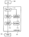
- FIG. 1 is a block diagram showing a functional configuration of the machining support system.
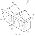
- FIG. 2 is a perspective view showing a material, an object, and a removal region.
- FIG. 3 is a block diagram illustrating a functional configuration of the process group creation unit.
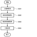
- FIG. 4 is a flowchart showing a process flow of the process group creation unit.
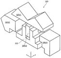
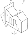
- FIG. 5 is a perspective view showing the object and the removal region separately.
- FIG. 6 is a perspective view showing a state in which the total removal region is divided by another temporary plane.
- FIG. 7 is a perspective view showing the number of the divided removal regions and the respective open surface portions.
- FIG. 8 is a diagram showing a tree structure of a process group in the middle of creation.
- FIG. 1 is a block diagram showing a functional configuration of the machining support system.
- FIG. 2 is a perspective view showing a material, an object, and a removal region.
- FIG. 3 is a block diagram illustrating a functional configuration of the process group creation unit
- FIG. 9 is a perspective view showing the number of open surface portions of the removal region included in SRV2.
- FIG. 10 is a diagram showing a part of the tree structure of the process group being created.
- FIG. 11 is a perspective view showing the number of open surface portions of the removal region included in the SRV 4.
- FIG. 12 is a diagram showing all the patterns of the removal region processing order in SRV4.
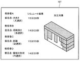
- FIG. 13 is a diagram illustrating an image presented by the brother node presentation unit on the display device.
- FIG. 14 is a flowchart showing the flow of processing of the learning unit.
- FIG. 15 is a diagram showing a screen for selecting a professor.
- FIG. 16 is a flowchart showing the flow of processing of the support unit.
- FIG. 17 is a diagram showing another screen for selecting a professor.
- FIG. 15 is a diagram showing a screen for selecting a professor.
- FIG. 18 is a diagram showing the trend information.
- FIG. 19 is a diagram showing variations of the removal shape information.
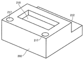
- FIG. 20 is a perspective view illustrating an example of an object.
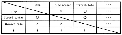
- FIG. 21 is a brute force table showing the processing order.
- FIG. 22 is a diagram showing a relative comparison of processing priorities.
- FIG. 1 is a block diagram showing a functional configuration of the machining support system.
- FIG. 2 is a perspective view showing a material, an object, and a removal area.
- the processing support system 100 removes the plurality of removal regions 205 of the material 200 in order to remove the total removal region 201 and obtains a plurality of objects 202 having a predetermined shape.
- This is a system for determining at least one process from a process group that is a set of processes.
- the processing support system 100 includes a process group creation unit 101, a learning unit 103, and a support unit 105.
- FIG. 3 is a block diagram showing the functional configuration of the process group creation unit.
- the process group creating unit 101 includes a process group that is a set of a plurality of processes for removing a plurality of removal regions of a material to obtain an object having a predetermined shape.
- a processing unit to be created which is a system realized by causing a computer to execute software (program).
- the process group creation unit 101 includes an inquiry unit 111, a divided plane determination unit 112, a next total removal area determination unit 113, a process candidate determination unit 114, and an order adjustment unit 115 as functional units realized by a computer.
- the computer is an electronic computer that includes a CPU (central processing unit) and has general configurations such as input / output means such as a display device and an input device, and storage means such as a memory and an external storage device.
- the inquiry unit 111 is cut out from the material 200 and the material data indicating the three-dimensional shape of the material 200 to a computer that implements the process group creation unit 101 or so-called CAD software 300 that is executed by another computer. It is a processing part which provides the target object data which shows the three-dimensional shape of the target object 202 to be displayed. Further, the inquiry unit 111 determines a plane portion existing on the surface of the virtual total removal region 201 that is a lump three-dimensional region to be removed from the material 200 by removal processing based on the material data and the object data. It is a processing unit that obtains, for each provisional plane 203, the number of divisions that is the number of provisional areas obtained by dividing the total removal area 201 by one provisional plane 203 including a plane part.
- the extraction of the total removal region 201 is performed by a three-dimensional shape difference calculation using the material data and the object data.
- the provisional plane 203 includes not only a plane perpendicular to the XYZ axis in the drawing but also a plane disposed obliquely with respect to these planes.
- the XYZ axes in the drawing may coincide with the axes of the processing machine.
- the inquiry unit 111 only needs to acquire the provisional plane 203 and the number of divisions associated with the provisional plane 203 in the total removal area 201 by designating the material data and the object data. It is not always necessary to have material data and object data. On the other hand, there is no denying that the inquiry unit 111 extracts the total removal area 201 based on the material data and the object data, specifies the plane part, and calculates the division number.
- the division plane determination unit 112 is a processing unit that determines the provisional plane 203 having a division number of 3 or more as a division plane that divides the total removal area 201 based on the provisional plane 203 and the number of divisions acquired by the inquiry unit 111. is there. In addition, when there are a plurality of provisional planes 203 having a division number of 3 or more, each may be determined as a division plane, and the following processing may be performed for each division plane to present a plurality of patterns. . The provisional plane 203 having the largest number of divisions may be used as the division plane.
- the provisional plane 203 is determined as a divided plane.
- the next total removal area determination unit 113 sets a predetermined condition among a plurality of division removal areas (hereinafter, abbreviated as SRV) divided by the division plane determined by the division plane determination unit 112. This is a processing unit that determines one of the areas other than one satisfied divided removal area as the next total removal area 201.
- SRV division removal areas
- the predetermined condition is, for example, (1) closest to the cutting tool. (2) There are the most open face portions (Open Face) that are surfaces that come into contact with the atmosphere. (3) The volume is the largest.
- next total removal area determination unit 113 does not function when the division plane determination unit 112 determines that the maximum number of divisions is two.
- the inquiry unit 111 sets the number of divisions for all the temporary planes 203 of the new total removal area 201 by the CAD software 300.
- the division plane determination unit 112 determines the provisional plane 203 having the number of divisions obtained by the inquiry unit 111 of 3 or more (for example, the maximum) as the next division plane.
- the process candidate determination unit 114 acquires the number of open surface portions that are surfaces that come into contact with the atmosphere in the divided removal regions divided by the divided planes determined by the divided plane determination unit 112. Then, the region having the largest number of open surface portions is determined as a removal region, and the number of open surface portions is further acquired for the remaining divided removal regions obtained by virtually removing the determined removal region, and the number of open surface portions is the largest.
- the processing unit determines an area as the next removal area and uses the determined order of the removal areas as a processing order.
- the division removal region with the largest open surface portion is a region where the cutting tool can be easily approached in the actual cutting process and the restrictions on the usable tools are relaxed. It becomes a high area.
- the open surface portion is generally described as a surface in contact with the atmosphere.
- the number of open surface portions may not be the exact number of planes.
- SRV1 when viewed from above (when viewed in the negative direction of the Z axis in the figure), four planes are observed, but SRV1 is each of the X axis, the Y axis, and the Z axis. If it is covered with a virtual rectangular parallelepiped formed by a plane intersecting at right angles to the four planes, the four planes viewed from above are covered with one plane, so the number of open surface portions of the part may be considered as one. According to this concept, the number of open surface portions of the entire SRV 1 is 5.
- a surface substantially in contact with the atmosphere may be considered as the number of open surface portions. Further, in consideration of the characteristics of the processing machine, the number of open surface portions may be determined by an approximate surface on which the cutting tool can enter. Specifically, the surface of the virtual rectangular parallelepiped where the material is held (chucked) may be not included in the open surface portion even if it is in contact with the atmosphere.
- the number of open surface portions may be obtained by calculation by the process candidate determination unit 114 or may be obtained by inquiring the CAD software 300.
- the order adjustment unit 115 is a processing unit that acquires the processing constraint condition for the division removal region and changes the processing order determined by the process candidate determination unit 114 based on the processing constraint condition.
- the processing constraint condition is a condition that when a coaxial through hole is provided in two regions of the object 202, the through hole is formed before removing the divided removal region sandwiched between the two regions. It can be illustrated.
- the order adjustment unit 115 may acquire a processing target region that is not specified by the division plane determination unit 112 in advance, and may additionally insert the processing target region at an appropriate position in the processing order.
- the division removal area to be removed using the same cutting tool makes the machining order continuous
- the division removal area having the same required dimensional tolerance makes the machining order continuous, the required perpendicularity, parallelism,
- the order adjustment unit 115 may add the following processing constraint conditions. For example, machining is performed from the divided removal area on the side close to the cutting tool, and machining is performed from the divided removal area having a large volume.
- the process group creating unit 101 outputs, to the learning unit 103, process groups that are a plurality of process candidates that are processing orders of the division plane determined by the division plane determination unit 112 and the division removal area divided by the division plane. To do.
- FIG. 4 is a flowchart showing a process flow of the process group creation unit.
- the inquiry unit 111 presents material data and object data to the CAD software 300, and obtains a block of total removal areas 201 from the CAD software 300 (S101).
- the total removal area 201 is data similar to the material data and the object data. Also, depending on the material data and the object data, there may be a case where there are a plurality of total removal areas 201. In this case, the following processing may be performed for each total removal area 201.
- the inquiry unit 111 extracts the provisional plane 203 including a plane portion existing on the surface of the acquired total removal area 201, and calculates the division number obtained when the total removal area 201 is divided by the provisional plane 203 by CAD.
- the software 300 is inquired and the result is acquired (S102). This process is performed for all of the provisional plane 203 including the slope existing on the surface of the total removal region 201.
- the number of divisions is 4, as shown by a, b, c, and d.
- the number of divisions is 2 as shown by a and b.
- the divided plane determination unit 112 extracts, for example, the provisional plane 203 associated with the maximum number of divisions, and determines the provisional plane 203 as the division plane (S103).
- the number of divisions based on the provisional plane 203 shown in FIG. 2 is four, which is the largest, so this provisional plane 203 is determined as the division plane.
- the division plane determination unit 112 determines all the provisional planes 203 as division planes.
- the maximum number of divisions is 3 or more and there are provisional planes 203 having the same number of divisions, the following processing may be performed for each division plane, and the provisional plane 203 acquired last is used as the division plane. You may perform the process of.
- the next total removal area determination unit 113 selects one of the areas other than the division removal area having the largest number of open surface portions as the next total removal area 201 for the division removal areas a, b, c, and d shown in FIG. (S104).
- the number of open surface portions of the divided removal region a is 5
- the number of open surface portions of the divided removal region b is 4
- the number of open surface portions of the divided removal region c is 2
- the number of open surface portions of the divided removal region d is Therefore, a region other than the division removal region a, for example, the division removal region b is determined as the next total removal region 201 (S104).
- the above processing is repeated until all the divided planes are determined (S105).
- the total removal region 201 is cut by the initially determined division plane (the provisional plane 203 shown in FIG. 2), it is divided into four regions SRV1 to SRV4. Since any of the regions SRV2 to SRV4 is divided by any provisional plane 203, the number of divisions is 2 (the maximum number of division planes is 2), so any provisional plane 203 is determined as a division plane. Is done.
- the divided plane determination process ends.
- an area divided by the division plane determined when the maximum number of division planes is two is referred to as a microfabrication area (Primitive), and may be abbreviated as P.
- the process candidate determination unit 114 obtains the number of open surface portions that are surfaces that come into contact with the atmosphere for the divided removal area divided by the division plane determined by the division plane determination unit 112, and obtains the largest number of open surface portions. A large area is determined as a removal area (S106).
- the number of open surface portions of SRV1 to SRV4, which are regions divided by the division plane determined first, is calculated.
- the priority of the processing order is the highest. That is, SRV1 is processed first.
- the processing order is a tree structure as shown in FIG.
- the SRV 2 is divided into microfabricated regions P.
- the numbers of the open surface portions of P1 to P3 are indicated by numerals in parentheses in FIG. 9 (hereinafter, when the number of open surface portions is described, it is also described in the drawing).
- the processing order of P1 has the highest priority.
- the number of open surface portions of P2 is the same as the number of open surface portions of P3, and the processing order in SRV2 is divided into two cases as shown in FIG.
- SRV3 has one micro-machined area and remains as it is.
- SRV4 is divided into P5 to P10 as microfabrication regions.
- the processing order of the micro-processed region is determined in the descending order of the number of open surface portions as in SRV2, as shown in FIG. 12, a plurality of process candidates having a tree structure are calculated as a process group.
- the order adjustment unit 115 determines whether or not the processing restriction condition is included in the division removal area for which the processing order is determined (S108). If the processing restriction condition is included, the order is adjusted. (S109).
- the process group determined as described above is output to the learning unit 103.
- the process group creation unit 101 may be realized by a system separate from the processing support system 100. In this case, the machining support system 100 acquires a process group from the separate system.
- the learning unit 103 is a processing unit that performs learning by a professor selecting a process based on the process group acquired from the process group creation unit 101. As illustrated in FIG. An area information acquisition unit 132, a brother node presentation unit 133, an order selection unit 134, a related information storage unit 135, and a trend derivation unit 136 are provided.
- the machining support system 100 includes an operation device 108 that is a man-machine interface and a display device 107 that can display an image.
- the processing support system 100 includes a so-called touch screen in which a transparent touch pad as the operation device 108 is superimposed on the surface of the display device 107.
- the professor information acquisition unit 131 is a processing unit that acquires professor information for identifying a professor.
- the professor is a person who inputs information for learning, for example, a so-called expert who has a long experience of selecting a processing order and determining a process.
- the removal area information acquisition unit 132 is a processing unit that acquires removal area information including a plurality of features of the removal area 205 corresponding to sibling nodes that are part of the process group acquired from the process group creation unit 101.
- the sibling nodes are nodes having the same parent. For example, P7, P9, and P10 when P8 shown in FIG. In other words, the sibling node is the removal area 205 having the same processing priority in the obtained process group.
- the removal area information includes information indicating the characteristics of the removal area.
- the information indicating the feature of the removal region 205 is, for example, the geometric feature of the removal region.
- the geometric information included in the removal area information includes the size of the removal area, the position of the center of gravity of the removal area represented by XYZ coordinates, and the removal in the direction in which a tool such as a cutting tool enters.
- the depth of the area corresponds to the removal area corresponding to the parent node and sibling nodes, the depth of the area, the shape of the removal area in the plane perpendicular to the direction in which the tool such as the cutting tool enters, whether the removal area penetrates the object
- the distance to the removal region for example, the distance between the centers of gravity.
- geometric information may be determined based on a virtual shape such as a virtual rectangular parallelepiped that can include the removal region and has the smallest volume.
- the geometric information includes removal shape information that is information based on the shape of the removal region 205.
- the removal shape information is not particularly limited, but when information based on the nine shapes shown in FIG. 19 is used, it is possible to improve the reproducibility of a process suitable for processing.
- the removal area information may include information other than geometric information.
- the information included in the removal area information can include the mass of the removal area, the material, the presence / absence of use of cutting oil, the type of tool for removal processing, the finishing state, and the like.
- the sibling node presentation unit 133 is a processing unit that presents at least a part of the removal area information corresponding to the sibling node on the display device 107 or the like.
- the sibling node presenting unit 133 visually displays the shape of the removal region 205 corresponding to the node (for example, P7, P9, P10) and the shape of the object 202 at the same time. Are displayed on the display device 107.
- the object 202 is indicated by cross-shaped shading on the screen of the display device 107, and the removal area 205 that is the selection target is indicated by fine dots. Further, the removal area 205 that has already been selected and the removal area 205 in which the processing order has already been determined without any room for selection may not be displayed. Further, in order to clearly show the correspondence between the removal area 205 and the node, a sign (for example, P7, P9, P10) is displayed inside the removal area 205.
- the order selection unit 134 is a processing unit that acquires one of the sibling nodes corresponding to the removal region information selected by the teacher based on the plurality of removal region information presented by the brother node presentation unit 133. Specifically, for example, when the professor selects the removal information (node) corresponding to P10 by operating the operation device 108 on the display device 107, the order selection unit 134 displays the parent node as shown in FIG. The processing order is determined on the assumption that the removal region 205 to be removed next to P8 is the removal region 205 corresponding to P10.
- the brother node presentation unit 133 displays the removal area information corresponding to the selected removal area 205, for example, You may display by a pop-up etc. as shown in FIG.
- the order selection unit 134 may acquire the feature selected by the professor from the plurality of pieces of information included in the removal area information presented by the sibling node presentation unit 133 by pop-up or the like as the feature information.
- This feature information is used as a weight or the like when deriving trend information described later.
- the related information storage unit 135 includes a step determined based on repeated selection of the sibling node presented by the sibling node presenting unit 133 and the removal region 205 corresponding to the node selected by the order selection unit 134, and the process includes
- the storage device stores the related information in which the teacher information is associated with the processing information including the removal area information corresponding to each removal area.
- An apparatus for realizing the related information storage unit 135 is not particularly limited, and examples thereof include a volatile semiconductor memory, a nonvolatile semiconductor memory, and a hard disk drive.
- the trend deriving unit 136 is a processing unit that derives trend information indicating a process selection tendency corresponding to the teacher information from the related information accumulated in the related information accumulation unit 135 based on the processing information corresponding to the teacher.
- the trend deriving unit 136 extracts removal area information related to the node selected by the same professor (hereinafter sometimes referred to as “selection information”) for each sibling node, and relates to the node not selected. To be removed (hereinafter sometimes referred to as “non-selection information”). Then, the trend information is derived by comparing and analyzing each item corresponding to the selection information and the non-selection information.
- the comparative analysis is, for example, in the case where the criterion of the item is represented by a numerical value, in each item, the value included in the non-selected information is set as a threshold value, and whether the selection information exceeds or does not exceed the threshold value is determined.
- the analysis to be performed can be illustrated.
- the determination criterion is expressed by a value other than a numerical value, an analysis in which the determination criterion is determined based on whether or not the determination criterion of the selection information belongs to a predetermined classification can be exemplified.
- the trend deriving unit 136 derives trend information as follows. As shown in FIG. 18, the “size” which is the removal area information item has 35 times when the selection information larger than the non-selection information is selected, and 10 times when the smaller selection information is selected. ing. That is, if the size of the removal area of the selection information is larger than the non-selection information, a point (for example, 1) is given to the determination criterion “large”, and if it is smaller, a point is assigned to the determination criterion “small”.
- the X coordinate, the Y coordinate, the Z coordinate, the depth of the removal area, the distance from the parent node to the selection information, and the distance to the non-selection information are set as threshold values, respectively. Points are given to each criterion for larger cases. If the value is the same as the threshold value, points need not be given.
- a classification of “polygon”, “circular” and “other” is set, and the classification to which the shape of the selected information belongs Points are given to.
- the removal area penetrates the object, it is classified as ⁇ Yes '', if it does not penetrate, it is classified as ⁇ No '', and if the shape of the selection information and the shape of the non-selection information belong to different classifications, Points are given to the classification to which the shape of the selection information belongs.
- the tendency deriving unit 136 frequently selects all combinations of two types of information extracted from the plurality of removal shape information. It is preferable to derive the trend information by selecting the low and high. Specifically, when the removal processing is performed so that the shape of the target object 202 as shown in FIG. 20 is obtained, Step 212, Closed Pocket 218, and Through hole 217 exist as the removal shape information.
- the trend selection unit 136 learns the processing priority of the information based on the shape because the order selection unit 134 inputs to the system in an interactive manner which information based on which shape the teacher wants to process.
- the trend information is derived by selecting a high frequency and a low frequency selected by the teacher for all combinations of two types of information extracted from a plurality of types of removal shape information.
- a round-robin table as shown in FIG. 21 can be created.
- the trend deriving unit 136 derives the trend information by creating a plurality of round-robin tables based on the related information accumulated in the related information accumulating unit 135 after sufficient teaching from the professor.
- the trend deriving unit 136 further determines the priority using geometric features and derives the trend information. May be. For example, when there is information based on the same type of shape, such as Through hole 217 of the object 202 shown in FIG. 20, the geometric features of the two removal regions are obtained from the selection order of the teacher obtained in the order selection unit 134. Are compared relatively. As comparison targets, the volume (Volume) of the removal area, the position (Position) of the removal area expressed by setting a predetermined origin, the processing depth (Depth) of the removal area, and the relative position (Inside) from the center of the processing object and at least one) distance.
- the order selection unit 134 acquires the processing order selected by the professor in an interactive manner, calculates information based on the shape, and geometric information of the removal region 205 having the same processing priority, and generates the result shown in FIG. Relative comparisons as shown are performed, and trend information is derived using geometric features.
- the trend deriving unit 136 can derive the trend information of each professor by performing the above analysis for each professor information.
- the points given to each item need not be the same value, and the points may be changed based on the feature information corresponding to the information included in the removal information selected by the professor. Thereby, it becomes possible to strongly reflect the item of the removal area information consciously selected by the professor in the trend information.
- the selection of sibling nodes can be included in the trend information indicating the selection tendency between items.
- the weight is, for example, a quotient obtained by dividing a point having a larger number of points acquired for a predetermined item by all points assigned to the item. Specifically, based on the size shown in FIG. 18, the number of points with more points acquired is 35, the total number of points given is 45, and therefore the size is 0.78 which is a quotient of 35 / (35 + 10). It becomes the weight of.
- the weight of the item “X coordinate” is 0.75
- the weight of the item “Y coordinate” is 0.63
- the weight of the item “Z coordinate” is 0.67
- the weight of the item “depth” is 0.57
- the weight of the item “shape” is 0.60
- the weight of the item “penetration” is 0.67
- the weight of the item “distance” is 0.80.
- FIG. 14 is a flowchart showing a flow of processing of the learning unit.
- a professor inputs professor information using the operation device 108, and the professor information acquisition unit 131 acquires professor information for identifying the professor (S301).
- the removal area information acquisition unit 132 acquires from the process group creation unit 101 sibling nodes that are part of the process group and the removal area information of the removal area 205 corresponding thereto (S302).
- the removal area information acquisition unit 132 may acquire all of the process group and all the removal area information.
- the sibling node presentation unit 133 presents at least a part of the removal area information corresponding to the sibling node on the display device 107 (S303). In other words, the corresponding removal area information is presented only when it is necessary to select the removal area in the process group.
- the sibling node presentation unit 133 first displays the material 200 after deleting the SRV1 that has no room for selection, and highlights and displays the SRV2 and SRV4. , Prompt the choice.
- the professor selects one removal area information using the operation device 108.
- the order selection unit 134 acquires one of the sibling nodes corresponding to the selected removal area information (S304).
- the above operation is performed for all sibling nodes included in the process group (S305). Specifically, when the left side shown in FIG. 8 is selected, next, P2 and P3 shown in FIG. 10 are selected, and finally the professor is selected for all sibling nodes shown in FIG.
- the related information storage unit 135 associates one process selected from the process group with removal area information corresponding to each removal area included in the process and stores it as processing information, and further stores the processing information in the processing information.
- the professor information is associated and stored as related information.
- the above operation is performed until a plurality of different professors can sufficiently collect information on a plurality of materials 200 and a plurality of objects 202 (S307).
- the trend deriving unit 136 derives trend information indicating a process selection trend corresponding to the teacher information based on the processing information corresponding to each teacher from the related information stored in the related information storage unit 135.
- the support unit 105 is a processing unit that automatically selects one process from the process group according to the judgment tendency of the expert by selecting an expert who the operator wants to use as an example. And a professor selection unit 152 and a process determination unit 153.
- FIG. 15 is a diagram showing a screen for selecting a professor.
- the professor presenting unit 151 is a processing unit that presents professor information corresponding to a plurality of different professors on the display device 107 or the like.
- the professor presentation unit 151 presents trend information corresponding to each professor together with the professor information.
- the trend information to be presented may not be the trend information itself, but may be information that conceptually indicates the trend information.
- the professor selection unit 152 is a processing unit that acquires the professor information selected by the operator based on the professor information presented by the professor presentation unit 151. Specifically, for example, when the operator selects one of the professors displayed on the display device 107 by the operation of the operation device 108 on the display device 107, the professor selection unit 152 performs the operation Select professor information according to the content.
- the process determining unit 153 acquires a process group or the like in which at least one of the material 200 and the target object 202 is new from the process group creating unit 101, and uses the trend information corresponding to the professor information selected by the professor selecting unit 152.
- the processing unit determines at least one process from the process group.
- the process determining unit 153 for example, traces child nodes one step at a time from the root node of the tree-structured process group. If there is a sibling node, the process determining unit 153 selects 1 from the sibling node based on the trend information corresponding to the selected teacher information. Pick one node. Then, one process is determined by following the child nodes in the same manner from the selected nodes.
- FIG. 16 is a flowchart showing the processing flow of the support unit.
- the process determining unit 153 acquires a process group from the process group creating unit 101 (S501). Specifically, an operator who uses the machining support system 100 inputs information indicating the shape of the material 200 to be machined into the process group creation unit 101 or the CAD software 300, and the object that is the result of machining. By inputting information indicating the shape of the object 202, the process group creating unit 101 creates a process group, and the process determining unit 153 obtains the created process group.
- this description is an example and the acquisition timing of a process group may be other than this description.
- the professor presentation unit 151 presents professor information on the display device 107 or the like (S502).
- the operator who needs support selects a professor by operating the operation device 108 based on the presented professor information, and the professor selection unit 152 acquires the professor information selected by the operator using the operation device 108. (S503).
- the process determining unit 153 determines one process based on the trend information corresponding to the teacher information selected from the process group acquired from the process group creating unit 101.
- the determined process is sent to the CAM system 301 and executed.
- processing support system 100 it is possible to learn the skill of an expert who determines one process from the process group in software.
- a process that is assumed to be derived by a selected expert based on the learning result. Can be easily determined. Therefore, even an inexperienced person can realize highly efficient machining.
- the present invention is not limited to the above embodiment.
- another embodiment realized by arbitrarily combining the components described in this specification and excluding some of the components may be used as an embodiment of the present invention.
- the present invention includes modifications obtained by making various modifications conceivable by those skilled in the art without departing from the gist of the present invention, that is, the meaning described in the claims. It is.
- the support unit 105 of the processing support system 100 may further include a simulation unit 154.
- the simulating unit 154 Based on the process group acquired from the process group creating unit 101, the simulating unit 154 causes the process determining unit 153 to determine a corresponding number of processes using trend information corresponding to a plurality of professors, and It is a processing unit that simulates removal processing based on each process and creates result information indicating a simulation result.
- the teacher presenting unit 151 can present result information such as processing time together with the teacher information as shown in FIG.
- the simulation is not executed for all the processes included in the process group, but the process obtained based on the trend information of a plurality of professors is simulated, so the simulation result is acquired early. Therefore, it becomes possible to easily present more information to the operator.
- the method of determining the removal area is not limited to the above, and the removal area may be determined by an arbitrary method such that all of the provisional planes are divided surfaces.
- the division surface for determining the removal area has been described as a plane, the division surface is not limited to a plane, and a cylindrical surface or the like is used when a material such as a lathe is rotated and a cutting tool does not rotate. It does not matter as a dividing plane.
- the determination of the process group is not limited to the method.
- the process group is indicated by a tree structure.
- the processing support system is a great support tool for making the decision. Therefore, not only when the operator of the machining support system has little experience, but also an experienced operator, it is possible to grasp the decision making contents of various professors in a visualized situation. It is possible to promote high leveling of decision making.
- the removal area information can be presented by any method such as text or voice.
- processing machine to which the result of the processing support system 100 is applied is not particularly limited, and examples thereof include a machining center, an NC lathe, and an electric discharge machine that can control the processing by an NC program.
- the present invention can be used for designing a machining process when an object is manufactured using an NC machine or the like.
Landscapes
- Engineering & Computer Science (AREA)
- General Engineering & Computer Science (AREA)
- Manufacturing & Machinery (AREA)
- Quality & Reliability (AREA)
- Physics & Mathematics (AREA)
- General Physics & Mathematics (AREA)
- Automation & Control Theory (AREA)
- General Factory Administration (AREA)
- Numerical Control (AREA)
Abstract
木構造で表現された工程群から1つの工程を決定する加工支援システム(100)であって、教授者情報を取得する教授者情報取得部(131)と、兄弟ノードに対応する除去領域情報を取得する除去領域情報取得部(132)と、兄弟ノードに対応する除去領域情報の少なくとも一部を提示する兄弟ノード提示部(133)と、提示された複数の除去領域情報に基づき、教授者が選定した兄弟ノードうちの1ノードを取得する順序選択部(134)と、複数の除去領域情報の提示とその選定の繰り返しに基づき決定された工程と除去領域情報とが関連付けられた加工情報に教授者情報を関連付けた関連情報を記憶する関連情報蓄積部(135)と、関連情報から加工情報に基づき教授者情報毎に工程選定の傾向を示す傾向情報を導出する傾向導出部(136)とを備える加工支援システム。
Description
本願発明は、素材の一部を切削などにより除去して所定の形状の対象物を得るための加工を支援する加工支援システムに関する。
製品形状が多様化・複雑化している昨今では、機械加工分野において、加工順序や加工条件などを決定する加工準備時間が大きくなるといった問題がある。
そこで、非特許文献1には、加工の結果物である製品形状の特徴を表現する位相情報と実際に加工された際の加工条件とを関連づけてデータベース化し、加工事例を再利用して機械加工の作業設計を自動的に行うシステムが記載されている。
白瀬敬一 他、「加工事例を再利用してNCプログラムを作成する機械加工用作業設計システム」、日本機械学会論文集81巻832号(2015)
ところが、機械加工の作業設計を自動的に行うシステムでは、1つの工程が決定されるのではなく、多数の工程が算出されるため、作業者が複数の工程から1つの工程を決定する必要が生じる。また、従来は、工程を自動で決めるシステムには、熟練者のノウハウや経験を生かして作業設計をするものがないため、最終的には、1つの工程を決定するために熟練が必要となっている。
本願発明は、上記課題に鑑みなされたものであり、経験の少ない技術者においても、熟練者のように複数の工程から好適と考えられる工程を決定することができる加工支援システムの提供を目的としている。
上記目的を達成するために、本願発明の1つである加工支援システムは、操作者が素材の複数の除去領域を除去加工して所定の形状の対象物を得るために複数の工程の集合である工程群から少なくとも1つの工程を決定する加工支援システムであって、教授者を識別する教授者情報を取得する教授者情報取得部と、木構造で表現される工程群の一部である兄弟ノードに対応する前記除去領域の特徴を示す除去領域情報を取得する除去領域情報取得部と、前記兄弟ノードに対応する除去領域情報の少なくとも一部を提示する兄弟ノード提示部と、提示された兄弟ノードにそれぞれ対応した除去領域情報に基づき、前記教授者が選定した除去領域情報に対応するノードを取得する順序選択部と、複数の除去領域情報の提示とその選定の繰り返しに基づき決定された工程と、前記工程に含まれる各ノードにそれぞれ対応する除去領域情報とを含む加工情報に教授者情報を関連付けた関連情報を記憶する関連情報蓄積部と、関連情報蓄積部に蓄積された関連情報から加工情報に基づき教授者情報毎に工程選定の傾向を示す傾向情報を導出する傾向導出部とを備える。
これによれば、例えば熟練の教授者が木構造の工程群から選定した工程に除去領域情報を関連付けた加工情報をデータベースとして蓄積していくことができる。また、このデータベースに基づき教授者毎の工程を選択する傾向(癖)を示す傾向情報を作成し、未経験者や経験の浅い操作者を支援することが可能となる。
また、前記操作者が、前記加工支援システムを使用し加工順序を決定する場合に、前記関連情報蓄積部及び前記傾向情報のうち少なくとも1つを教授者ごとに可視的に表示させ、前記表示された内容に基づき、前記操作者が教授者を選定することにより加工順序を決定してもよい。
これによれば、未経験者や経験の浅い操作者が表示に基づき教授者を選定するだけで、選定された教授者の傾向に対応した加工順序を決定することができる。
また、前記素材の形状を示す素材データと前記対象物の形状を示す対象物データとを取得し、除去する一塊の領域である総除去領域の表面の一部を含む分割面により前記総除去領域を分割して得られる除去領域に基づき工程群を作成する工程群作成部をさらに備えてもよい。
これによれば、工程群を他のシステムから取得するのではなく、加工支援システムに素材データと対象物データとを入力すれば、傾向情報を導出するためのデータベースを作成することが可能となる。
また、除去領域情報は、前記除去領域の幾何的な特徴を含むものでもよい。
これによれば、比較的簡単に教授者に対応する傾向情報を導出することが可能となる。
また、前記兄弟ノード提示部は、ノードに対応する前記除去領域の形状と前記対象物の形状とを同時に視覚的に表示させてもよい。
これによれば、教授者が除去領域の形を認識しながら加工の順序を選択するため、加工順序を選択する際の教授者の傾向をより強く反映させることが可能となる。
また、前記順序選択部は、順序の選択に加えて前記教授者が選定した除去領域情報に含まれる情報の少なくとも1つを特徴情報として取得してもよい。
これによれば、教授者の無意識的な傾向ばかりでなく、意識的な傾向を傾向情報に反映させることが可能となる。
また、複数の前記教授者に対応する教授者情報を提示する教授者提示部と、前記教授者提示部により提示された教授者情報に基づき、前記操作者が選定した教授者情報を取得する教授者選定部と、工程群を取得し、選定された教授者情報に対応する傾向情報に基づき工程群から少なくとも1つの工程を決定する工程決定部とをさらに備えてもよい。
これによれば、熟練者で無い者であっても加工支援システムによって提示された熟練者を選択することで熟練者に近い工程を選定することができる。従って、熟練者で無い者が、熟練者が選定したような工程によって、素材を除去加工して対象物を得ることができるため、効率的な除去加工をすることができるようになる。
また、前記教授者提示部は、教授者情報と共に傾向情報を提示してもかまわない。
これによれば、除去加工にある程度の知識のある操作者等の場合、傾向情報に基づきより具体的に教授者を選択できるようになる。
また、教授者にそれぞれ対応する傾向情報に基づき工程群から複数の工程を前記工程決定部にそれぞれ決定させると共に、決定された工程に基づき除去加工をシミュレートし、シミュレート結果を示す結果情報を作成するシミュレート部をさらに備え、前記教授者提示部は、結果情報を教授者情報と共に提示してもよい。
これによれば、工程群のなかから教授者の傾向により選定された工程についてシミュレートを行うため、シミュレート数を低減できる。また、素材から対象物を得るために必要な時間などの結果情報に基づきより具体的に教授者を選定することが可能となる。
なお、前記加工支援システムが含む各処理をコンピュータに実行させるためのプログラムを実施することも本願発明の実施に該当する。無論、そのプログラムが記録された記録媒体を実施することも本願発明の実施に該当する。
本願発明によれば、熟練作業者などが実施する加工工程を選定する癖などを加工支援システムが学習することができ、学習結果に基づき初心者などでも熟練者が実施するような加工工程を簡単に実行することが可能となる。
次に、本願発明に係る加工支援システム100の実施の形態について、図面を参照しつつ説明する。なお、以下の実施の形態は、本願発明に係る加工支援システム100の一例を示したものに過ぎない。従って本願発明は、以下の実施の形態を参考に請求の範囲の文言によって範囲が画定されるものであり、以下の実施の形態のみに限定されるものではない。よって、以下の実施の形態における構成要素のうち、本願発明の最上位概念を示す独立請求項に記載されていない構成要素については、本願発明の課題を達成するのに必ずしも必要ではないが、より好ましい形態を構成するものとして説明される。
また、図面は、本願発明を示すために適宜強調や省略、比率の調整を行った模式的な図となっており、実際の形状や位置関係、比率とは異なる場合がある。
図1は、加工支援システムの機能構成を示すブロック図である。
図2は、素材、対象物、および、除去領域を示す斜視図である。
これらの図に示すように、加工支援システム100は、素材200の複数の除去領域205を順番に除去加工して総除去領域201を除去し、所定の形状の対象物202を得るために複数の工程の集合である工程群から少なくとも1つの工程を決定するシステムである。本実施の形態の場合、加工支援システム100は、工程群作成部101と、学習部103と、支援部105とを備えている。
図3は、工程群作成部の機能構成を示すブロック図である。
同図に示すように本実施の形態に係る工程群作成部101は、素材の複数の除去領域を除去加工して所定の形状の対象物を得るための複数の工程の集合である工程群を作成する処理部であり、コンピュータにソフトウエア(プログラム)を実行させることで実現されるシステムである。工程群作成部101は、コンピュータにより実現される機能部として、問合せ部111と、分割平面決定部112と、次総除去領域決定部113と、工程候補決定部114と、順序調整部115とを備えている。なお、コンピュータとは、CPU(中央処理装置)を備え、表示装置や入力装置などの入出力手段、メモリや外部記憶装置などの記憶手段など一般的な構成を備えた電子計算機である。
問合せ部111は、工程群作成部101を実現しているコンピュータ、または、別のコンピュータで実行されているいわゆるCADソフトウエア300などに素材200の三次元形状を示す素材データと、素材200から切り出される対象物202の三次元形状を示す対象物データとを提供する処理部である。また、問合せ部111は、素材データと対象物データとに基づいて、除去加工により素材200から除去する一塊の三次元的な領域である仮想的な総除去領域201の表面に存在する平面部を取得したり、平面部を含む一つの仮平面203により総除去領域201を分割して得られる仮領域の数である分割数を仮平面203毎に取得する処理部である。
ここで、総除去領域201の抽出は、素材データと対象物データを用いた三次元形状の差演算により行われる。また、仮平面203は、図中XYZの軸に直角に交わる平面ばかりでなく、これらの平面に対し斜めに配置される平面も含まれる。また、図中のXYZ軸は、加工機の軸と一致していてもよい。
なお、問合せ部111は、素材データと対象物データとを指定することにより、総除去領域201において、仮平面203とこれに紐付けられた分割数を取得すればよく、工程群作成部101が素材データと対象物データを必ずしも保有している必要はない。一方、問合せ部111が、素材データと対象物データとに基づき、総除去領域201を抽出し、平面部を特定し、分割数を算出することを否定するものではない。
分割平面決定部112は、問合せ部111が取得した仮平面203と分割数とに基づき、分割数が3以上となる仮平面203を、総除去領域201を分割する分割平面として決定する処理部である。なお、分割数が3以上となる仮平面203が複数存在する場合は、それぞれを分割平面として決定し、それぞれの分割平面毎に以下に示す処理を行い、複数のパターンを提示しても構わない。また、分割数が最も多い仮平面203を分割平面としても構わない。
ここで、分割平面決定部112は、最大の分割数が2であった場合、つまり、総除去領域201を仮平面203により分割して得られる分割数が全て2であった場合は、全ての仮平面203を分割平面として決定する。
次総除去領域決定部113は、分割平面決定部112により決定された分割平面によって分割される複数の分割除去領域(以下、略字でSRVと記載する場合がある。)の内、所定の条件を満たした一つの分割除去領域以外の領域の一つを次の総除去領域201として決定する処理部である。
ここで、所定の条件とは、例えば、(1)切削工具に最も近い。(2)大気に触れる面である開放面部(Open Face)が最も多い。(3)体積が最も大きいなどである。
また、次総除去領域決定部113は、分割平面決定部112が最大の分割数が2であると判断した場合は、機能しないものとなっている。
なお本実施形態の場合、問合せ部111は、次総除去領域決定部113によって総除去領域201が決定された場合、新たな総除去領域201の全ての仮平面203について分割数をCADソフトウエア300に問合せる。また、分割平面決定部112は、問合せ部111により得られた分割数が3以上(例えば最大)となる仮平面203を次の分割平面として決定する。
工程候補決定部114は、分割平面決定部112により決定された分割平面で分割された分割除去領域について、大気に触れる面である開放面部の数を取得する。そして、開放面部の数の最も多い領域を除去領域として決定し、決定された除去領域を仮想的に除去した残りの分割除去領域についてさらに開放面部の数を取得し、開放面部の数の最も多い領域を次の除去領域として決定し、決定された除去領域の順番を加工順序とする処理部である。
以上の処理により、開放面部が最大の分割除去領域は、実際の切削工程においては切削工具の接近が容易となり、使用可能な工具への制約も緩くなる領域であるため、加工順序の優先度が高い領域となる。
ここで、開放面部とは、一般的には大気と接触している面として説明される。なお、開放面部の数は厳密な平面の数でなくてもよい。例えば図5に示すように、SRV1では、上方から見た場合(図中Z軸負の方向に見た場合)、平面が4面看取されるが、SRV1をX軸Y軸Z軸のそれぞれに直角に交差する面で形成される仮想的な直方体で覆うとすると、上方から見た四つの平面は1平面で覆われるため、当該部分の開放面部の数を1と考えてもかまわない。この考え方によるとSRV1全体の開放面部の数は、5となる。よって、開放面部の数に関しては、実質的に大気と接触している面を、開放面部の数と考えても構わない。また、加工機の特性を考慮し、切削工具が進入できるおおよその面で開放面部の数を決定してもよい。具体的には、前記仮想的な直方体のうち、素材が保持(チャック)されている面は大気と接触していても開放面部に含めないとしても構わない。
なお、開放面部の数は、工程候補決定部114が計算により取得してもよく、CADソフトウエア300に問いあわせることにより取得しても構わない。
順序調整部115は、分割除去領域についての加工制約条件を取得し、当該加工制約条件に基づいて、工程候補決定部114で決定された加工順序を入れ替える処理部である。
ここで、加工制約条件とは、対象物202の二つの領域に同軸の貫通孔を設ける場合、二つの領域に挟まれている分割除去領域を除去する前に貫通孔を穿設するという条件を例示できる。この場合、貫通孔を設ける領域は、平面で囲まれた領域ではないため、分割平面決定部112によっては特定されない。そこで、順序調整部115は、このような分割平面決定部112では特定されない加工対象領域を予め取得しておき、加工順序の適切な箇所に追加挿入しても構わない。
その他加工条件としては、同じ切削工具を用いて除去する分割除去領域は加工順序を連続させる、要求される寸法公差が同じ分割除去領域は加工順序を連続させる、要求される直角度、平行度、平面度などが所定の閾値よりも厳しい場合、分割除去領域の加工順序を調整するなどである。さらに、順序調整部115は、次の加工制約条件を加えても構わない。例えば、切削工具に近い側の分割除去領域から加工する、体積の大きい分割除去領域から加工する、などである。
以上により、工程群作成部101は、分割平面決定部112で決定された分割平面や分割平面で分割された分割除去領域の加工順である複数の工程候補である工程群を学習部103に出力する。
次に、上記工程群作成部101の各処理部を機能させて分割平面と加工順序とを決定する流れを説明する。
図4は、工程群作成部の処理の流れを示すフローチャートである。
まず、問合せ部111がCADソフトウエア300に素材データと対象物データとを提示し、CADソフトウエア300から一塊の総除去領域201を取得する(S101)。なお、総除去領域201とは、素材データや対象物データと同様のデータである。また、素材データと対象物データによっては、総除去領域201が複数存在する場合も発生するが、その場合は各総除去領域201について下記の処理を行えばよい。
次に、問合せ部111が、取得した総除去領域201について表面に存在する平面部を含む仮平面203を抽出し、当該仮平面203によって総除去領域201を分割した場合に得られる分割数をCADソフトウエア300に問いあわせて結果を取得する(S102)。この処理は、総除去領域201の表面に存在する斜面を含む仮平面203の全てについて行われる。
具体的に例えば、図2に示すような仮平面203で総除去領域201を分割すると、分割数は、a、b、c、dで示すように4となる。一方、図6に示すような仮平面203で総除去領域201を分割すると、分割数は、a、bで示すように2となる。
次に、分割平面決定部112は、例えば最大の分割数に紐付けられた仮平面203を抽出し、当該仮平面203を分割平面として決定する(S103)。本実施形態の場合、図2に示す仮平面203に基づく分割数が4で最大であるため、この仮平面203が分割平面として決定される。
また、分割平面決定部112は、取得した最大の分割数が2の場合、全ての仮平面203を分割平面として決定する。
このように、本実施形態では、最初に取得された総除去領域201の全体を全ての仮平面203で細分化することなく分割平面を容易に決定することが可能である。
なお、最大の分割数が3以上であって同じ分割数の仮平面203がある場合は、それぞれの分割平面について以下の処理を行ってもよく、最後に取得した仮平面203を分割平面として以下の処理を行ってもよい。
次に、次総除去領域決定部113は、図2に示す分割除去領域a、b、c、dについて開放面部の数が最も多い分割除去領域以外の領域の一つを次の総除去領域201として決定する(S104)。具体的には分割除去領域aの開放面部の数は5、分割除去領域bの開放面部の数は4、分割除去領域cの開放面部の数は2、分割除去領域dの開放面部の数は4であるので、分割除去領域a以外の領域、例えば分割除去領域bを次の総除去領域201として決定する(S104)。
以上の処理を全ての分割平面が決定されるまで繰り返し行う(S105)。本実施形態の場合、図7に示すように、最初に決定された分割平面(図2に示す仮平面203)で総除去領域201を切断すると、SRV1~SRV4の四つの領域に分割される。そして、SRV2~SRV4のいずれの領域についても、どのような仮平面203で分割しても分割数が2となるため(分割平面の最大数が2)、いずれの仮平面203も分割平面として決定される。以上のように、最初に取得された総除去領域201すべてについて分割平面が決定されると分割平面決定の処理が終了する。ここで、分割平面の最大数が2となった場合に決定された分割平面で分割された領域を微小加工領域(Primitive)とし、Pと略して記載する場合がある。
次に、工程候補決定部114は、分割平面決定部112により決定された分割平面で分割された分割除去領域について、大気に触れる面である開放面部の数を取得し、開放面部の数の最も多い領域を除去領域として決定する(S106)。
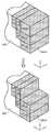
具体的には、図7に示すように、最初に決定される分割平面により分割される領域であるSRV1~SRV4の開放面部の数をそれぞれ算出する。本実施形態の場合、SRV1の開放面部の数が5と最も大きいので、加工順序の優先順位は最も高くなる。つまりSRV1が最初に加工されることになる。
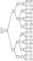
次に、SRV2とSRV4との開放面部の数は4であって、同じであるので、加工順序は、図8に示すように、木構造になる。
次に、SRV2の加工順序の決め方を示す。図9の上段に示すように、SRV2は、微小加工領域Pに分けられる。P1~P3の開放面部の数は、図9中の括弧内に数字で示されている(以下、開放面部の数を記載する場合には、同様に図の中に記載する。)。同図に示すように、P1の開放面部の数が最も大きいので、P1の加工順序が最優先となる。次の加工順を決めるには、図9の下段に示すように、P1を加工除去したと想定し、加工後のP2、P3の開放面部の数を取得する。この場合には、P2の開放面部の数とP3の開放面部の数とは同じであり、SRV2での加工順序は、図10に示すように、二つの場合に分かれる。
SRV3は、微小加工領域が一つであり、そのままになる。
SRV4は、図11に示すように、微小加工領域としてはP5~P10に分けられる。微小加工領域の加工順序は、SRV2で行った同様に開放面部の数の降順で決定すると、その結果は、図12に示すように、複数の木構造の工程候補が工程群として算出される。
次に、加工順序が決定された分割除去領域に加工制約条件が含まれているか否かを順序調整部115が判断し(S108)、加工制約条件が含まれている場合は、順序が調整されてもよい(S109)。
以上により、決定された工程群は、学習部103に出力される。
なお、工程群作成部101は、加工支援システム100とは別体のシステムによって実現されてもよい。この場合、加工支援システム100は、当該別体のシステムから工程群を取得する。
学習部103は、工程群作成部101から取得した工程群に基づき教授者が工程を選定することにより学習を行う処理部であり、図1に示すように、教授者情報取得部131と、除去領域情報取得部132と、兄弟ノード提示部133と、順序選択部134と、関連情報蓄積部135と、傾向導出部136とを備えている。
本実施の形態の場合、加工支援システム100は、マンマシンインターフェースである操作装置108と画像を表示することのできる表示装置107とを備えている。具体的に加工支援システム100は、表示装置107の表面に操作装置108としての透明なタッチパットが重ねられたいわゆるタッチスクリーンを備えている。
教授者情報取得部131は、教授者を識別する教授者情報を取得する処理部である。ここで、教授者とは、学習のための情報を入力する者であり、例えば、加工順序を選定し工程を決定する経験の長いいわゆる熟練者などである。
除去領域情報取得部132は、工程群作成部101から取得した工程群の一部である兄弟ノードに対応する除去領域205の複数の特徴を含む除去領域情報を取得する処理部である。ここで、兄弟ノードとは、同じ親を持つノードであり、例えば、図12に示すP8を親ノードとした場合のP7、P9、P10が該当する。換言すると、兄弟ノードとは、得られた工程群の中で加工優先度が同じ除去領域205である。
また、除去領域情報とは、除去領域の特徴を示す情報を含むものである。除去領域205の特徴を示す情報とは、例えば、除去領域の幾何的な特徴などである。具体的に例えば、除去領域情報に含まれる幾何的な情報としては、除去領域の大きさ、XYZ座標などで表される除去領域の重心などの位置、切削工具などの工具が侵入する方向における除去領域の深さ、切削工具などの工具が侵入する方向に直交する平面における除去領域の形、除去領域が対象物を貫通しているか否か、親ノードに対応する除去領域と兄弟ノードに対応する除去領域との距離、例えば重心間の距離などが例示できる。
さらに、また、除去領域を内包することができ、かつ、体積が最小の仮想的な直方体などの仮想形状に基づき幾何的な情報を定めてもよい。
また、幾何的な情報には、除去領域205の形状に基づく情報である除去形状情報が含まれることが望ましい。除去形状情報は、特に限定されるものではないが、図19に示す9つの形状に基づく情報を用いた場合、加工に適した工程の再現性を向上させることが可能である。具体的には、1)面全体に対して除去加工する:Face211、2)面を2分割した一方を除去加工し、加工後の状況が階段状になる:Step212、3)両端が開口する溝を除去加工により形成する:Open slot213、4)面の角部を除去加工する:Open pocket214、5)一端のみ開口する溝を除去加工により形成する:Closed slot215、6)矩形の貫通孔を除去加工する:Through pocket216、7)円形の貫通孔を除去加工する:Through hole217、8)矩形の底有り穴を除去加工する:Closed pocket218、9)円形の底有り穴を除去加工するClosed hole219、以上が本実施の形態で採用された9つの除去形状情報である。
除去領域情報は、幾何的な情報以外の情報を含んでいてもかまわない。例えば、除去領域情報に含まれる情報としては、除去領域の質量、材質、切削油の使用の有無、除去加工する場合の工具の種類、仕上げの状態などを挙示することができる。
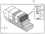
兄弟ノード提示部133は、兄弟ノードに対応する除去領域情報の少なくとも一部を表示装置107等に提示する処理部である。本実施の形態の場合、兄弟ノード提示部133は、図13に示すように、ノード(例えば、P7、P9、P10)に対応する除去領域205の形状と対象物202の形状とを同時に視覚的に表示装置107に表示させている。
なお、表示装置107の画面上において対象物202は交差状の網掛けで示されており、選択対象である除去領域205は、細かなドットで示されている。また、既に選択されている除去領域205、および、選択の余地なく既に加工順序が定まっている除去領域205は、表示しない様にしてもかまわない。また、除去領域205とノードとの対応関係を明確に示すため除去領域205の内部には符合(例えば、P7、P9、P10)が表示されている。
順序選択部134は、兄弟ノード提示部133により提示された複数の除去領域情報に基づき、教授者が選定した除去領域情報に対応する兄弟ノードうちの1ノードを取得する処理部である。具体的に例えば、表示装置107上の操作装置108の操作により、教授者がP10に対応する除去用行き情報(ノード)を選択した場合、順序選択部134は、図12に示すように親ノードであるP8の次に除去する除去領域205は、P10に対応する除去領域205であるとして加工順序を決定していく。
また、兄弟ノード提示部133は、教授者が操作装置108を用いて1つの除去領域205に対応する除去領域情報を選択した際、選択されている除去領域205に対応する除去領域情報を、例えば図13に示すようにポップアップなどで表示させてもよい。
順序選択部134は、兄弟ノード提示部133がポップアップなどにより提示した除去領域情報に含まれる複数の情報のうち教授者が選定した特徴を特徴情報として取得してもかまわない。この特徴情報は、後述の傾向情報を導出する際の重み等として用いられる。
関連情報蓄積部135は、兄弟ノード提示部133が提示する兄弟ノードとこれに対応して順序選択部134によるノードである除去領域205の選定の繰り返しに基づき決定された工程と、前記工程に含まれる各除去領域に対応する除去領域情報とを含む加工情報に教授者情報を関連付けた関連情報を記憶する蓄積装置である。関連情報蓄積部135を実現する装置は特に限定されるわけではなく、揮発性半導体メモリや不揮発性半導体メモリ、ハードディスクドライブなどを例示することができる。
傾向導出部136は、関連情報蓄積部135に蓄積された関連情報から教授者に対応する加工情報に基づき教授者情報に対応する工程選定の傾向を示す傾向情報を導出する処理部である。傾向導出部136は、兄弟ノードのそれぞれについて、同じ教授者が選択したノードに関連する除去領域情報(以下「選択情報」と記載する場合がある。)を抽出し、選択しなかったノードに関連する除去領域情報(以下「非選択情報」と記載する場合がある。)を抽出する。そして、選択情報と非選択情報との対応する各項目について比較分析することにより傾向情報を導出する。
ここで、比較分析とは、例えば項目の判断基準が数値で表されるものの場合は、各項目において、非選択情報に含まれる値を閾値として選択情報が前記閾値を超えるか超えないかで判断する分析を例示できる。また、判断基準が数値以外で表されるものの場合は、選択情報の判断基準が所定の分類に属するか属さないかで判断する分析を例示できる。
具体的に例えば、傾向導出部136は、次のようにして傾向情報を導出する。図18に示すように、除去領域情報の項目である「大きさ」について非選択情報よりも選択情報が大きいものが選択された場合が35回、小さいものが選択された場合が10回存在している。つまり、選択情報の除去領域の大きさが非選択情報よりも大きければ判断基準の「大」にポイント(例えば1)を付与し、小さければ判断基準の「小」にポイントを付与している。同様に、X座標、Y座標、Z座標、除去領域の深さ、親ノードから選択情報までの距離と非選択情報までの距離についてそれぞれ非選択情報の値を閾値として、閾値未満の場合、閾値より大の場合のそれぞれの判断基準にポイントを付与する。なお、閾値と同値の場合はポイントを付与しなくてもよい。
また、削工具などの工具が侵入する方向に直交する平面における除去領域の形については「多角形」と「円形」と「その他」との分類を設定しておき、選択情報の形状が属する分類にポイントを付与する。また、除去領域が対象物を貫通している場合は「有」、貫通していない場合は「無」として分類し、選択情報の形状と非選択情報の形状とが異なる分類に属する場合は、選択情報の形状が属する分類にポイントを付与する。
以上のポイントの付与を兄弟ノードのそれぞれに対して行い、得られた結果を集計することで、所定の教授者情報に関連する傾向情報を導出することができる。具体的には、兄弟ノードの選定にあたり、項目内における選択の傾向を示す傾向情報を導出することができる。
また、除去領域情報に複数の除去形状情報が含まれている場合、傾向導出部136は、複数の除去形状情報から抽出される2種類の情報の全ての組み合わせについて教授者が選定する頻度の高いものと低いものとを選別することで傾向情報を導出することが好ましい。具体的には、図20に示すような対象物202の形状となるように除去加工する場合、除去形状情報としては、Step212、Closed Pocket218およびThrough hole217が存在することになる。順序選択部134によって、教授者がどの形状に基づく情報を優先して加工したいかが対話形式でシステムに入力されているため、傾向導出部136は、形状に基づく情報の加工優先度を学習する。具体的に例えば、複数種類の除去形状情報から抽出される2種類の情報の全ての組み合わせについてそれぞれ教授者が選定する頻度の高いものと低いものとを選別することで傾向情報を導出する。つまり教授者がClosed pocket218、Step212、Through hole217の順での加工を選択した場合、図21のような総当たり表が作成できる。教授者からの教示が十分に行われて関連情報蓄積部135に蓄積された関連情報に基づき、傾向導出部136は、複数の総当たり表を作成することにより傾向情報を導出する。
このように、除去形状情報から傾向情報を導出することにより、教授者が除去領域を選択する順序にある程度のゆらぎがあったとしても、教授者の選択傾向が正しく反映された傾向情報を導出することが可能となる。
さらに、傾向導出部136は、同種類の除去形状情報に、加工優先度が同じ除去領域が複数存在する場合は、その中でさらに幾何的な特徴を用いて優先度を決定し傾向情報を導出してもよい。例えば、図20に示す対象物202のThrough hole217のように同種類の形状に基づく情報が存在する場合、順序選択部134において入手した教授者の選択順序から、2つの除去領域の幾何的な特徴を相対的に比較する。比較対象としては、除去領域の体積(Volume)、所定の原点を定めて表される除去領域の位置(Position)、除去領域の加工深さ(Depth)、加工対象の中心からの相対位置(Inside and outside)との距離の少なくとも1つを用いる。
具体的には、教授者が選択した加工順序を対話形式により順序選択部134が取得し、形状に基づく情報、および加工優先度が同じ除去領域205の幾何的な情報を計算して図22に示すような相対的な比較を行い、幾何的な特徴を用いて傾向情報を導出する。
傾向導出部136は、上記の分析を教授者情報毎に行う事で、教授者それぞれの傾向情報を導出することができる。
なお、各項目に付与するポイントは同じ値でなくとも良く、教授者が選定した除去情報に含まれる情報に対応する特徴情報に基づきポイントを変更してもかまわない。これにより、教授者が意識的に選択した除去領域情報の項目を傾向情報に強く反映させることが可能となる。
さらに、項目それぞれの重みを導出することにより、兄弟ノード選定にあたり、項目間における選択の傾向を示す傾向情報に含ませることができる。重みとは、例えば、所定の項目について獲得したポイントが多い方のポイントをその項目に付与した全ポイントを除することにより得られる商である。具体的に図18に示す大きさに基づき説明すると、獲得したポイントが多い方のポイントは35、付与された全ポイントは45、したがって、35/(35+10)の商である0.78が大きさの重みとなる。ちなみに、項目「X座標」の重みは0.75、項目「Y座標」の重みは0.63、項目「Z座標」の重みは0.67、項目「深さ」の重みは0.57、項目「形」の重みは0.60、項目「貫通」の重みは0.67、項目「距離」の重みは0.80である。
図14は、学習部の処理の流れを示すフローチャートである。
まず、教授者が操作装置108を用いて教授者情報を入力し、教授者情報取得部131は、教授者を識別する教授者情報を取得する(S301)。
次に、除去領域情報取得部132は、工程群作成部101から工程群の一部である兄弟ノードと、これに対応する除去領域205の除去領域情報を取得する(S302)。なお、除去領域情報取得部132は、工程群の全てと全ての除去領域情報を取得してもかまわない。
次に、兄弟ノード提示部133は、兄弟ノードに対応する除去領域情報の少なくとも一部を表示装置107に提示する(S303)。つまり、工程群の内、除去領域を選択する必要がある場合のみ該当する除去領域情報を提示する。
本実施の形態の場合、図8に示すように、兄弟ノード提示部133は、選択の余地のないSRV1を削除した後の、素材200を最初に表示し、SRV2とSRV4を強調して表示し、選択を促す。
次に兄弟ノード提示部133により提示された複数の除去領域情報に基づき、教授者が操作装置108を用いて1つの除去領域情報を選定する。順序選択部134は、選定された除去領域情報に対応する兄弟ノードうちの1ノードを取得する(S304)。
以上の動作を、工程群に含まれる全兄弟ノードについて実施する(S305)。具体的には、図8に示す左側が選択された場合、次に、図10に示すP2とP3とを選択させ、最後に図12に示される全兄弟ノードについて教授者に選択させる。
次に、関連情報蓄積部135は、工程群から選定された1つの工程と、前記工程に含まれる各除去領域に対応する除去領域情報とを関連付けて加工情報として記憶し、さらに当該加工情報に教授者情報を関連づけて関連情報として記憶する。
以上の動作を、複数の異なる教授者に対し、複数の素材200、複数の対象物202について十分に情報が収集できるまで行う(S307)。
次に、傾向導出部136は、関連情報蓄積部135に蓄積された関連情報から各教授者に対応する加工情報に基づき教授者情報に対応する工程選定の傾向を示す傾向情報を導出する。
支援部105は、操作者が手本としたい熟練者を選択することで、自動的に熟練者の判断傾向に従った1つの工程を工程群から選び出す処理部であって、教授者提示部151と、教授者選定部152と、工程決定部153とを備えている。
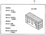
図15は、教授者を選定するための画面を示す図である。
教授者提示部151は、複数の異なる教授者にそれぞれ対応する教授者情報を表示装置107等に提示する処理部である。本実施の形態の場合、教授者提示部151は、教授者情報と共に各教授者に対応した傾向情報を提示している。なお、提示する傾向情報は、傾向情報そのものでなくとも良く、傾向情報を概念的に示す情報などでもかまわない。
教授者選定部152は、教授者提示部151により提示された教授者情報に基づき、操作者が選定した教授者情報を取得する処理部である。具体的に例えば、表示装置107上の操作装置108の操作により、操作者が表示装置107に表示される教授者の1つを操作装置108により選択することで、教授者選定部152は、操作内容に従った教授者情報を選定する。
工程決定部153は、素材200、および、対象物202の少なくとも一方が新しい工程群などを工程群作成部101から取得し、教授者選定部152により選定された教授者情報に対応する傾向情報に基づき工程群から少なくとも1つの工程を決定する処理部である。工程決定部153は、例えば、木構造の工程群の根ノードから1段ずつ子ノードを辿り、兄弟ノードが存在する場合は、選定された教授者情報に対応する傾向情報に基づき兄弟ノードから1つのノードを選び出す。そして、選び出されたノードから子ノードを同様に辿ることで1つの工程を決定する。
図16は、支援部の処理の流れを示すフローチャートである。
まず、工程決定部153が、工程群作成部101より工程群を取得する(S501)。具体的には、加工支援システム100を利用する操作者が、工程群作成部101やCADソフトウエア300に加工対象である素材200の形状などを示す情報を入力し、加工の結果物である対象物202の形状などを示す情報を入力することにより工程群作成部101が工程群を作成し、工程決定部153が作成された工程群を取得する。なお、本記載は一例であり、工程群の取得タイミングは、本記載以外でもかまわない。
次に、加工工程の決定にあたり、教授者提示部151が表示装置107などに教授者情報を提示する(S502)。支援を要する操作者は、提示された教授者情報に基づき操作装置108を操作することにより教授者を選定し、教授者選定部152は、操作者が操作装置108により選定した教授者情報を取得する(S503)。
次に、工程決定部153は、工程群作成部101から取得した工程群から選定された教授者情報に対応する傾向情報に基づき1つの工程を決定する。決定された工程は、CAMシステム301に送られて、実行される。
以上の加工支援システム100によれば、工程群の中から1つの工程を決定する熟練者の技術をソフトウエア的に学習することができる。また、未経験者や経験の浅い者が新しい形状の素材200から新しい形状の対象物202を加工する場合などにおいても、学習結果に基づいて、選定した熟練者であれば導き出すと想定される工程を簡単に決定することができる。従って、未経験者などでも高効率の加工を実現することが可能となる。
また、ある程度の加工経験のある者の場合、工程選定の傾向(癖)を頼りにして熟練者を選定することもでき、工程選定のスキルアップを図ることも可能となる。
なお、本願発明は、上記実施の形態に限定されるものではない。例えば、本明細書において記載した構成要素を任意に組み合わせて、また、構成要素のいくつかを除外して実現される別の実施の形態を本願発明の実施の形態としてもよい。また、上記実施の形態に対して本願発明の主旨、すなわち、請求の範囲に記載される文言が示す意味を逸脱しない範囲で当業者が思いつく各種変形を施して得られる変形例も本願発明に含まれる。
例えば、図1に示しているように、加工支援システム100の支援部105はさらに、シミュレート部154を備えていてもかまわない。
シミュレート部154は、工程群作成部101から取得した工程群に基づき、複数の教授者に対応する傾向情報を用いて対応する数の工程を工程決定部153に決定させ、決定された複数の工程に基づき除去加工をそれぞれシミュレートし、シミュレート結果を示す結果情報を作成する処理部である。
シミュレート部154が除去加工をした場合、教授者提示部151は、図17に示すように、加工時間などの結果情報を教授者情報と共に提示することができる。
これによれば、工程群に含まれる全ての工程についてシミュレートを実行するのではなく、複数の教授者の傾向情報に基づき得られた工程についてシミュレートするため、シミュレート結果を早期に取得することができ、より多くの情報を簡単に操作者に提示することが可能となる。
また、除去領域を決定する方法は、上記に限定されるものではなく、仮平面の全てを分割面とするなど任意の方法により除去領域を決定してもかまわない。
また、除去領域を決定するための分割面を平面として説明したが、分割面は平面に限定されるものではなく、旋盤など素材を回転させ切削工具が回転しない場合などは筒状の面などを分割面としてもかまわない。
また、開放面部の数に基づき加工順を決定し工程群を作成する場合を説明したが、工程群の決定は、当該方法に限定されるわけではない。特に、素材の複数の除去領域を除去加工して所定の形状の対象物を得るために複数の工程の集合である工程群があるときに、その工程群の中に、木構造で示されるような選択肢があり、その選択肢の中から、どの選択肢を選ぶかを操作者が決定する場合に、加工支援システムはその意思決定する為の大きな支援ツールとなるものである。従って、加工支援システムの操作者の経験が少ない場合だけでなく、経験豊富な操作者であっても、色々な教授者の意思決定内容を、可視化した状況で把握することができ、操作者の意思決定に関する高位平準化を促進することが可能である。
また、本実施形態の場合、除去領域の形状などをディスプレイなどに視覚的に表示させる場合を説明したが、除去領域情報の提示は、テキストや音声など任意の方法で提示することができる。
また、加工支援システム100の結果を適用する加工機は、特に限定されるものでは無く、例えば、NCプログラムにより加工を制御できる、マシニングセンター、NC旋盤、放電加工機などを例示することができる。
本願発明は、NC加工機などを用いて対象物を製造する際における加工工程の設計などに利用可能である。
100 加工支援システム
101 工程群作成部
103 学習部
105 支援部
107 表示装置
108 操作装置
111 問合せ部
112 分割平面決定部
113 次総除去領域決定部
114 工程候補決定部
115 順序調整部
131 教授者情報取得部
132 除去領域情報取得部
133 兄弟ノード提示部
134 順序選択部
135 関連情報蓄積部
136 傾向導出部
151 教授者提示部
152 教授者選定部
153 工程決定部
154 シミュレート部
200 素材
201 総除去領域
202 対象物
203 仮平面
205 除去領域
300 CADソフトウエア
301 CAMシステム
101 工程群作成部
103 学習部
105 支援部
107 表示装置
108 操作装置
111 問合せ部
112 分割平面決定部
113 次総除去領域決定部
114 工程候補決定部
115 順序調整部
131 教授者情報取得部
132 除去領域情報取得部
133 兄弟ノード提示部
134 順序選択部
135 関連情報蓄積部
136 傾向導出部
151 教授者提示部
152 教授者選定部
153 工程決定部
154 シミュレート部
200 素材
201 総除去領域
202 対象物
203 仮平面
205 除去領域
300 CADソフトウエア
301 CAMシステム
Claims (11)
- 操作者が素材の複数の除去領域を順番に除去加工して所定の形状の対象物を得るための工程を複数種類有する工程群から少なくとも1つの工程を決定する加工支援システムであって、
当該加工支援システムに工程を教授する複数の教授者をそれぞれ識別する教授者情報を取得する教授者情報取得部と、
木構造で表現される工程群の一部であり1つのノードから分岐した複数のノードである兄弟ノードに対応する前記除去領域の複数の特徴を含む除去領域情報を取得する除去領域情報取得部と、
前記兄弟ノードに対応する除去領域情報の少なくとも一部の特徴を提示する兄弟ノード提示部と、
提示された特徴に基づき、前記教授者が選定したノードを取得する順序選択部と、
複数の特徴の提示と前記教授者による選定の繰り返しに基づき決定された工程と、前記工程に含まれる各ノードにそれぞれ対応する除去領域情報とを含む加工情報に前記教授者情報を関連付けた関連情報を記憶する関連情報蓄積部と、
関連情報蓄積部に蓄積された関連情報から加工情報に基づき教授者情報毎に各教授者が選定する工程の選定傾向を示す傾向情報を導出する傾向導出部と
を備える加工支援システム。 - 前記操作者が、前記加工支援システムを使用し加工順序を決定する場合に、
前記関連情報蓄積部及び前記傾向情報のうち少なくとも1つを教授者ごとに可視的に表示させ、
前記表示された内容に基づき、前記操作者が教授者を選定することにより加工順序を決定する
請求項1に記載の加工支援システム。 - 前記素材の形状を示す素材データと前記対象物の形状を示す対象物データとを取得し、除去する一塊の領域である総除去領域の表面の一部を含む分割面により前記総除去領域を分割して得られる除去領域に基づき工程群を作成する工程群作成部をさらに備える
請求項1または2に記載の加工支援システム。 - 除去領域情報は、前記除去領域の幾何的な特徴を含む
請求項1から3のいずれかに記載の加工支援システム。 - 前記兄弟ノード提示部は、ノードに対応する前記除去領域の形状と前記対象物の形状とを同時に視覚的に表示させる
請求項1から4のいずれかに記載の加工支援システム。 - 前記順序選択部は、順序の選択に加えて前記教授者が選定した除去領域情報に含まれる情報の少なくとも1つを特徴情報として取得する
請求項1から5のいずれかに記載の加工支援システム。 - 複数の前記教授者に対応する教授者情報を提示する教授者提示部と、
前記教授者提示部により提示された教授者情報に基づき、前記操作者が選定した教授者情報を取得する教授者選定部と、
工程群を取得し、選定された教授者情報に対応する傾向情報に基づき工程群から少なくとも1つの工程を決定する工程決定部と
をさらに備える請求項1から6のいずれかに記載の加工支援システム。 - 前記教授者提示部は、教授者情報と共に傾向情報を提示する
請求項7に記載の加工支援システム。 - 複数の傾向情報に基づき工程群から複数の工程を前記工程決定部にそれぞれ決定させると共に、決定された工程に基づき除去加工をシミュレートし、シミュレート結果を示す結果情報を作成するシミュレート部をさらに備え、
前記教授者提示部は、結果情報を教授者情報と共に提示する
請求項7または8に記載の加工支援システム。 - 前記除去領域情報には、複数種類の除去領域の形状に基づく情報である除去形状情報が含まれ、
前記傾向導出部は、複数種類の前記除去形状情報から抽出される2種類以上の情報の全ての組み合わせについてそれぞれ教授者が選定する頻度の高いものと低いものとを選別することで傾向情報を導出する
請求項1から9のいずれかに記載の加工支援システム。 - 前記傾向導出部は、同種類の除去形状情報に、優先度が同じ除去領域が存在する場合、さらに幾何的な特徴として除去領域の体積、所定の原点を定めて表される除去領域の位置、除去領域の加工深さ、加工対象の中心からの相対位置の少なくとも1つを用いて傾向情報を導出する
請求項10に記載の加工支援システム。
Priority Applications (1)
| Application Number | Priority Date | Filing Date | Title |
|---|---|---|---|
| JP2019504503A JP7182791B2 (ja) | 2017-03-07 | 2018-02-28 | 加工支援システム |
Applications Claiming Priority (2)
| Application Number | Priority Date | Filing Date | Title |
|---|---|---|---|
| JP2017043061 | 2017-03-07 | ||
| JP2017-043061 | 2017-03-07 |
Publications (1)
| Publication Number | Publication Date |
|---|---|
| WO2018163932A1 true WO2018163932A1 (ja) | 2018-09-13 |
Family
ID=63449070
Family Applications (1)
| Application Number | Title | Priority Date | Filing Date |
|---|---|---|---|
| PCT/JP2018/007527 Ceased WO2018163932A1 (ja) | 2017-03-07 | 2018-02-28 | 加工支援システム |
Country Status (2)
| Country | Link |
|---|---|
| JP (1) | JP7182791B2 (ja) |
| WO (1) | WO2018163932A1 (ja) |
Citations (1)
| Publication number | Priority date | Publication date | Assignee | Title |
|---|---|---|---|---|
| JP2005309713A (ja) * | 2004-04-21 | 2005-11-04 | New Industry Research Organization | 工程設計支援システム及び支援方法 |
-
2018
- 2018-02-28 WO PCT/JP2018/007527 patent/WO2018163932A1/ja not_active Ceased
- 2018-02-28 JP JP2019504503A patent/JP7182791B2/ja active Active
Patent Citations (1)
| Publication number | Priority date | Publication date | Assignee | Title |
|---|---|---|---|---|
| JP2005309713A (ja) * | 2004-04-21 | 2005-11-04 | New Industry Research Organization | 工程設計支援システム及び支援方法 |
Also Published As
| Publication number | Publication date |
|---|---|
| JP7182791B2 (ja) | 2022-12-05 |
| JPWO2018163932A1 (ja) | 2020-01-09 |
Similar Documents
| Publication | Publication Date | Title |
|---|---|---|
| JP5925976B1 (ja) | 加工プログラム編集支援装置 | |
| JP6787661B2 (ja) | 工作物の機械加工のシミュレート | |
| EP2148258B1 (en) | Simulation or modeling method of cutting, program for that method, and medium recording that program | |
| EP2669824A1 (en) | Design support system, method and program | |
| KR20130049164A (ko) | 워크피스의 기계가공의 시뮬레이션 | |
| US20140324904A1 (en) | Similar design structure search device and similar design structure search method | |
| JP5436731B1 (ja) | 数値制御加工プログラム作成装置 | |
| EP2749973A2 (en) | Method and apparatus for a cutting process automatic generation tool of cam | |
| Lynn et al. | Toward rapid manufacturability analysis tools for engineering design education | |
| US6862560B1 (en) | Machining simulation method and apparatus | |
| JP5990662B2 (ja) | 加工プログラム編集支援装置 | |
| EP3535628A1 (en) | Process and system for providing a machining method for manufacturing a feature in a part | |
| Fletcher et al. | The development of an integrated haptic VR machining environment for the automatic generation of process plans | |
| JP6242709B2 (ja) | 組立順序生成装置および組立順序生成方法 | |
| KR101919572B1 (ko) | 초기 의장 설계용 3차원 모델 생성 방법 및 그 장치 | |
| KR100539949B1 (ko) | 3차원 유한요소격자 생성 방법 및 그 장치 | |
| JP5595146B2 (ja) | 加工シミュレーション装置および最適工程決定装置 | |
| CN109857064B (zh) | 信息处理装置 | |
| US20200038917A1 (en) | Shape packing technique | |
| JPWO2013128625A1 (ja) | 加工プログラム生成装置、加工プログラム生成方法、および加工プログラム生成プログラム | |
| JP2018180693A (ja) | 作業指示生成装置および作業指示生成方法 | |
| CN108227628B (zh) | 加工程序解析装置、计算机可读取的记录介质和加工程序解析方法 | |
| WO2018163932A1 (ja) | 加工支援システム | |
| US7197442B2 (en) | Mesh creating device, mesh creating method and mesh creating program | |
| WO2006027882A1 (ja) | 3次元モデル自動構築システム |
Legal Events
| Date | Code | Title | Description |
|---|---|---|---|
| 121 | Ep: the epo has been informed by wipo that ep was designated in this application |
Ref document number: 18764038 Country of ref document: EP Kind code of ref document: A1 |
|
| ENP | Entry into the national phase |
Ref document number: 2019504503 Country of ref document: JP Kind code of ref document: A |
|
| NENP | Non-entry into the national phase |
Ref country code: DE |
|
| 122 | Ep: pct application non-entry in european phase |
Ref document number: 18764038 Country of ref document: EP Kind code of ref document: A1 |