WO2018163764A1 - 熱媒体用基材、並びにそれを用いた熱輸送システムおよびヒートポンプシステム - Google Patents
熱媒体用基材、並びにそれを用いた熱輸送システムおよびヒートポンプシステム Download PDFInfo
- Publication number
- WO2018163764A1 WO2018163764A1 PCT/JP2018/005621 JP2018005621W WO2018163764A1 WO 2018163764 A1 WO2018163764 A1 WO 2018163764A1 JP 2018005621 W JP2018005621 W JP 2018005621W WO 2018163764 A1 WO2018163764 A1 WO 2018163764A1
- Authority
- WO
- WIPO (PCT)
- Prior art keywords
- heat
- heat medium
- ionic liquid
- hydrophilic ionic
- base material
- Prior art date
- Legal status (The legal status is an assumption and is not a legal conclusion. Google has not performed a legal analysis and makes no representation as to the accuracy of the status listed.)
- Ceased
Links
Images
Classifications
-
- C—CHEMISTRY; METALLURGY
- C09—DYES; PAINTS; POLISHES; NATURAL RESINS; ADHESIVES; COMPOSITIONS NOT OTHERWISE PROVIDED FOR; APPLICATIONS OF MATERIALS NOT OTHERWISE PROVIDED FOR
- C09K—MATERIALS FOR MISCELLANEOUS APPLICATIONS, NOT PROVIDED FOR ELSEWHERE
- C09K5/00—Heat-transfer, heat-exchange or heat-storage materials, e.g. refrigerants; Materials for the production of heat or cold by chemical reactions other than by combustion
- C09K5/20—Antifreeze additives therefor, e.g. for radiator liquids
-
- C—CHEMISTRY; METALLURGY
- C09—DYES; PAINTS; POLISHES; NATURAL RESINS; ADHESIVES; COMPOSITIONS NOT OTHERWISE PROVIDED FOR; APPLICATIONS OF MATERIALS NOT OTHERWISE PROVIDED FOR
- C09K—MATERIALS FOR MISCELLANEOUS APPLICATIONS, NOT PROVIDED FOR ELSEWHERE
- C09K5/00—Heat-transfer, heat-exchange or heat-storage materials, e.g. refrigerants; Materials for the production of heat or cold by chemical reactions other than by combustion
- C09K5/08—Materials not undergoing a change of physical state when used
- C09K5/10—Liquid materials
-
- F—MECHANICAL ENGINEERING; LIGHTING; HEATING; WEAPONS; BLASTING
- F01—MACHINES OR ENGINES IN GENERAL; ENGINE PLANTS IN GENERAL; STEAM ENGINES
- F01P—COOLING OF MACHINES OR ENGINES IN GENERAL; COOLING OF INTERNAL-COMBUSTION ENGINES
- F01P3/00—Liquid cooling
-
- F—MECHANICAL ENGINEERING; LIGHTING; HEATING; WEAPONS; BLASTING
- F01—MACHINES OR ENGINES IN GENERAL; ENGINE PLANTS IN GENERAL; STEAM ENGINES
- F01P—COOLING OF MACHINES OR ENGINES IN GENERAL; COOLING OF INTERNAL-COMBUSTION ENGINES
- F01P3/00—Liquid cooling
- F01P3/20—Cooling circuits not specific to a single part of engine or machine
-
- F—MECHANICAL ENGINEERING; LIGHTING; HEATING; WEAPONS; BLASTING
- F01—MACHINES OR ENGINES IN GENERAL; ENGINE PLANTS IN GENERAL; STEAM ENGINES
- F01P—COOLING OF MACHINES OR ENGINES IN GENERAL; COOLING OF INTERNAL-COMBUSTION ENGINES
- F01P7/00—Controlling of coolant flow
- F01P7/02—Controlling of coolant flow the coolant being cooling-air
- F01P7/04—Controlling of coolant flow the coolant being cooling-air by varying pump speed, e.g. by changing pump-drive gear ratio
- F01P7/048—Controlling of coolant flow the coolant being cooling-air by varying pump speed, e.g. by changing pump-drive gear ratio using electrical drives
-
- F—MECHANICAL ENGINEERING; LIGHTING; HEATING; WEAPONS; BLASTING
- F25—REFRIGERATION OR COOLING; COMBINED HEATING AND REFRIGERATION SYSTEMS; HEAT PUMP SYSTEMS; MANUFACTURE OR STORAGE OF ICE; LIQUEFACTION SOLIDIFICATION OF GASES
- F25B—REFRIGERATION MACHINES, PLANTS OR SYSTEMS; COMBINED HEATING AND REFRIGERATION SYSTEMS; HEAT PUMP SYSTEMS
- F25B1/00—Compression machines, plants or systems with non-reversible cycle
-
- F—MECHANICAL ENGINEERING; LIGHTING; HEATING; WEAPONS; BLASTING
- F28—HEAT EXCHANGE IN GENERAL
- F28F—DETAILS OF HEAT-EXCHANGE AND HEAT-TRANSFER APPARATUS, OF GENERAL APPLICATION
- F28F23/00—Features relating to the use of intermediate heat-exchange materials, e.g. selection of compositions
-
- F—MECHANICAL ENGINEERING; LIGHTING; HEATING; WEAPONS; BLASTING
- F28—HEAT EXCHANGE IN GENERAL
- F28D—HEAT-EXCHANGE APPARATUS, NOT PROVIDED FOR IN ANOTHER SUBCLASS, IN WHICH THE HEAT-EXCHANGE MEDIA DO NOT COME INTO DIRECT CONTACT
- F28D15/00—Heat-exchange apparatus with the intermediate heat-transfer medium in closed tubes passing into or through the conduit walls ; Heat-exchange apparatus employing intermediate heat-transfer medium or bodies
-
- F—MECHANICAL ENGINEERING; LIGHTING; HEATING; WEAPONS; BLASTING
- F28—HEAT EXCHANGE IN GENERAL
- F28D—HEAT-EXCHANGE APPARATUS, NOT PROVIDED FOR IN ANOTHER SUBCLASS, IN WHICH THE HEAT-EXCHANGE MEDIA DO NOT COME INTO DIRECT CONTACT
- F28D21/00—Heat-exchange apparatus not covered by any of the groups F28D1/00 - F28D20/00
- F28D2021/0019—Other heat exchangers for particular applications; Heat exchange systems not otherwise provided for
- F28D2021/008—Other heat exchangers for particular applications; Heat exchange systems not otherwise provided for for vehicles
Definitions
- the present disclosure relates to a base material for a heat medium, and a heat transport system and a heat pump system using the same.
- an ethylene glycol aqueous solution has been widely used as a base material for a heat medium such as cooling water or antifreeze for an internal combustion engine or a heat pump.
- the physical properties of the 50 v / v% ethylene glycol aqueous solution are a freezing point of ⁇ 32 ° C. and a kinematic viscosity at 25 ° C. of 3.13 mm 2 / s.
- Such an ethylene glycol aqueous solution has a high viscosity due to a decrease in outside air temperature. For this reason, when ethylene glycol aqueous solution is used as cooling water, the burden to the water pump which circulates cooling water at the time of low external temperature becomes large, and the lifetime of a water pump may be shortened by extension.
- Patent Document 1 discloses a base material for a heat medium containing 20 to 70% by weight of formamide and / or methylformamide, 80 to 30% by weight of water, and 0.1 to 10% by weight of a rust inhibitor.
- the base material for heat medium of Patent Document 1 has the same thermal properties (freezing point, etc.) as a conventional ethylene glycol aqueous solution, and has a kinematic viscosity of about 1.5 mm 2 / s. For this reason, the viscosity to cooling water can be reduced and the load to a water pump can be reduced.
- the concentration of formamide may decrease at a high temperature when the heat medium substrate of Patent Document 1 is used as cooling water for an internal combustion engine or an antifreeze for a heat pump.
- the use temperature of the cooling water for the internal combustion engine is ⁇ 34 ° C. to 120 ° C.
- the use temperature of the antifreeze for the heat pump is ⁇ 30 ° C. to 100 ° C.
- the formamide concentration then drops by about 20% after 100 hours at 80 ° C.
- Patent Document 2 discloses an ionic liquid having a predetermined pyrrolidinium cation as a base material for a heat medium having good thermal stability.
- the base material for heat medium of Patent Document 2 may have a high kinematic viscosity.
- Patent Document 2 the one having the lowest viscosity is N-methoxymethyl-N-methylpyrrolidinium bis (fluorosulfonyl) amide (MMMP • FSA). And its viscosity is 20 cP.
- Patent Document 2 does not describe the density of the base material for the heat medium using MMMP ⁇ FSA as the ionic liquid, but the average value of the density of the similar system is 1.25 g / cc.
- the viscosity is 16 mm2 / s. This is about 5 times that of the conventional 50 v / v% ethylene glycol aqueous solution, which indicates that the kinematic viscosity of the heat medium substrate of Patent Document 2 is very high.
- the present disclosure aims to provide a heat medium substrate having a low viscosity and a low freezing point and high thermal stability, and a heat transport system and a heat pump system using the same.
- a substrate for a heat medium containing a hydrophilic ionic liquid having predetermined physical properties and water has a low viscosity, a low freezing point, and heat. It was found that the stability is high.
- the base material for a heat medium according to the first aspect of the present disclosure contains a hydrophilic ionic liquid and water, and the viscosity of the hydrophilic ionic liquid at 25 ° C. is 30 mPa ⁇ s or less.
- the ionic liquid has good thermal stability, the thermal stability of the base material for the heat medium can be ensured. Moreover, the kinematic viscosity of the base material for heat carriers can be reduced by setting the viscosity of the hydrophilic ionic liquid at 25 ° C. to 30 mPa ⁇ s or less. Furthermore, since the freezing point lowering effect can be obtained by dissolving the ionic liquid in water, a low freezing point can be realized.
- the base material for a heat medium according to the second aspect of the present disclosure contains a hydrophilic ionic liquid and water, and the molecular weight of the hydrophilic ionic liquid is 150 or less.
- the ionic liquid since the ionic liquid has good thermal stability, the thermal stability of the base material for the heat medium can be ensured.
- the molecular weight of the hydrophilic ionic liquid to 150 or less, the kinematic viscosity of the base material for the heat medium can be lowered.
- the freezing point lowering effect can be obtained by dissolving the ionic liquid in water, a low freezing point can be realized.
- the heat medium base material according to the present disclosure is applied to a heat medium of a heat pump hot water heater that is a heat pump system.
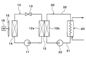
- the heat pump type water heater of the present embodiment includes a heat pump cycle 10, a radiator 20, a heat medium circulation circuit 30, and the like as shown in the overall configuration diagram of FIG.
- the heat pump hot water heater heats the heat medium by the heat pump cycle 10 and heats hot water as a fluid to be heated by using the heated heat medium as a heat source.
- the heat pump cycle 10 is a vapor compression refrigeration cycle for heating a heat medium.
- the radiator 20 is a heat exchanger that heats hot water by causing the heat medium heated in the heat pump cycle 10 and hot water to exchange heat and releasing the heat of the heat medium into the hot water.
- the heat medium circulation circuit 30 is a heat medium circuit that circulates the heat medium between the heat medium-refrigerant heat exchanger 12 and the radiator 20 of the heat pump cycle 10.
- the heat pump cycle 10 is configured by sequentially connecting a compressor 11, a heat medium-refrigerant heat exchanger 12, an expansion valve 13, and an evaporator 14 with piping.
- Compressor 11 sucks the refrigerant of heat pump cycle 10 and compresses and discharges it.
- the compressor 11 is an electric compressor that drives a fixed displacement compression mechanism with an electric motor.
- a refrigerant passage 12 a inlet side of the heat medium-refrigerant heat exchanger 12 is connected to the discharge port of the compressor 11.
- the heat medium-refrigerant heat exchanger 12 has a refrigerant passage 12 a for circulating the high-pressure refrigerant discharged from the compressor 11 and a heat medium passage 12 b for circulating the heat medium circulating in the heat medium circulation circuit 30.
- the heat medium-refrigerant heat exchanger 12 is a heat exchanger for heating that heats the heat medium by exchanging heat between the high-pressure refrigerant flowing through the refrigerant passage 12a and the heat medium flowing through the heat medium passage 12b.
- the inlet side of the expansion valve 13 is connected to the outlet side of the refrigerant passage 12 a of the heat medium-refrigerant heat exchanger 12.
- the expansion valve 13 is a variable throttle mechanism that decompresses and expands the refrigerant that has flowed out of the refrigerant passage 12a.
- the expansion valve 13 is an electric expansion valve having a valve body that can change the throttle opening degree and an electric actuator that changes the throttle opening degree of the valve body.
- the refrigerant inlet side of the evaporator 14 is connected to the outlet side of the expansion valve 13.
- the refrigerant outlet of the evaporator 14 is connected to the suction port side of the compressor 11.
- the evaporator 14 performs heat exchange between the low-pressure refrigerant decompressed by the expansion valve 13 and the outside air (outdoor air) blown by the blower fan 15, thereby evaporating the low-pressure refrigerant and exerting an endothermic effect. It is an outdoor heat exchanger.
- the blower fan 15 includes a fan motor 16, and the blower fan 15 can be rotated by rotating the fan motor 16.
- the heat medium circulation circuit 30 has a low temperature side heat medium passage 31 and a high temperature side heat medium passage 32.
- the low-temperature heat medium passage 31 guides the low-temperature heat medium radiated by the radiator 20 to the inlet side of the heat medium passage 12 b of the heat medium-refrigerant heat exchanger 12.
- the high temperature side heat medium pipe 32 guides the high temperature heat medium flowing out from the heat medium passage 12 b outlet side of the heat medium-refrigerant heat exchanger 12 to the inlet side of the radiator 20.
- a heat medium circulation pump 33 is disposed in the low temperature side heat medium pipe 31.
- the heat medium circulation pump 33 sucks the heat medium flowing out from the radiator 20 and pumps it to the heat medium passage 12b side of the heat medium-refrigerant heat exchanger 12.
- a heat medium base material containing a hydrophilic ionic liquid and water is used.
- a hydrophilic ionic liquid contained in the heat medium substrate one having a molecular weight of 150 or less or a viscosity at 25 ° C. of 30 mPa ⁇ s or less is used.
- the ionic liquid is a salt existing in a liquid and is a liquid compound composed only of ions (anions / cations).
- an ionic liquid maintains a liquid state even in a temperature range of ⁇ 30 ° C. to 300 ° C., and has a high heat resistance because there is little change in physical properties at temperatures exceeding 300 ° C.
- hydrophilic ionic liquid of this embodiment for example, as shown in Table 1 below, an ammonium-based ionic liquid or an imidazolium-based ionic liquid can be used.
- methylammonium ion (CH3NH3 +) or the like is used as the cation component of the ammonium-based ionic liquid.
- anion component of the ammonium ionic liquid nitrate ion (NO3-) or the like is used.
- methylammonium nitrate methylammonium nitrate
- Methylammonium nitrate has a small molecular weight of 150 or less and is light.
- imidazolium ion As the cation component of the imidazolium-based ionic liquid, imidazolium ion, more specifically 1-ethyl-3-methyl-imidazolium ion, or the like is used.
- anion component of the imidazolium-based ionic liquid (CN) 2N-, SCN-, Cl-, or the like is used.
- examples of imidazolium-based ionic liquids include 1-ethyl-3-methylimidazolium chloride (EMIC), 1-ethyl-3-methylimidazolium dicyanamide (EMID), and 1-ethyl-3-methylimidazolium.
- Thiocyanate (EMIT) is used.
- EMIC has a feature that its molecular weight is as small as 150 or less and light.
- EMID has a characteristic that the viscosity at 25 ° C. is as small as 21.4 mPa ⁇ s and the interaction between ions is small.
- EMIT has a characteristic that the viscosity at 25 ° C. is as small as 23.1 mPa ⁇ s and the interaction between ions is small.
- the freezing point and kinematic viscosity of the base material for a heat medium which is an aqueous solution obtained by mixing the above-described various ionic liquids with water, and an ethylene glycol aqueous solution as a comparative example were measured.
- the results are shown in Table 2 below.
- the freezing point was measured by differential operation calorimetry (DSC).
- the kinematic viscosity was measured at room temperature (25 ° C.) using a rotational viscometer (manufactured by Brookfield).
- the heat medium substrate of the present embodiment had a concentration of the ionic liquid contained of 50 wt% or more and a freezing point of ⁇ 30 ° C. or less. Since the freezing point of the ethylene glycol aqueous solution, which is a comparative example, is ⁇ 30 ° C. or lower, it can be said that the heat medium substrate of this embodiment has a freezing point substantially equal to that of the ethylene glycol aqueous solution.
- the base material for the heat medium of this embodiment has a kinematic viscosity at 25 ° C. equal to or lower than that of the ethylene glycol aqueous solution as a comparative example.
- the kinematic viscosity at 25 ° C. is 3.1 mm 2 / s or less, which is lower than the kinematic viscosity at 25 ° C. of the aqueous ethylene glycol solution.
- the kinematic viscosity at 25 ° C. is 1.61 mm 2 / s, which is about half the kinematic viscosity at 25 ° C. of the aqueous ethylene glycol solution.
- the base material for a heat medium of this embodiment contains a hydrophilic ionic liquid and water, that is, the hydrophilic ionic liquid is dissolved in water. According to this, since the ionic liquid has good thermal stability, it is possible to ensure the thermal stability of the heat medium substrate. Furthermore, since the freezing point lowering effect can be obtained by dissolving the ionic liquid in water, a low freezing point can be realized.
- a low-viscosity hydrophilic ionic liquid has a smaller Coulomb interaction between ions (anion-cation) than a solid salt in the first place.
- the kinematic viscosity of the base material for the heat medium can be reduced.
- the kinematic viscosity of the base material for heat medium can be reduced by making the molecular weight of the hydrophilic ionic liquid as small as 150 or less.
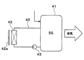
- the base material for a heat medium according to the present disclosure is applied to cooling water of a cooling system of an engine (internal combustion engine) used as one of driving power sources for a hybrid vehicle. That is, in this embodiment, the heat transport system according to the present disclosure is applied to an engine cooling system.
- the engine cooling system of the present embodiment is a system that cools the cooling water of the engine 41 with a radiator 42. That is, the engine cooling system of the present embodiment is a system that transports heat from the engine 41 to the radiator 42 via cooling water that is a liquid heat medium that flows through the cooling water flow path 40.
- Engine 41 is an energy conversion unit that generates heat when fuel, which is energy supplied from the outside, is converted into power, which is another form of energy.
- the radiator 42 exchanges heat with the exhaust heat of the engine 41 and exchanges heat between the cooling water that has become high temperature and the outside air (outside air) blown from the blower fan 42a, thereby cooling the cooling water. It is a vessel.
- the radiator 42 of the present embodiment corresponds to a heat radiating unit of the present disclosure.
- the blower fan 42a is an electric blower in which the operation rate, that is, the rotation speed (the amount of blown air) is controlled by a control voltage output from a control device (not shown).
- the engine 41 and the radiator 42 are connected by a cooling water passage 40 that forms a closed circuit between the engine 41 and the radiator 42.
- the cooling water channel 40 is provided with a pump 43 that circulates the cooling water through the cooling water channel 40.
- the cooling water in the cooling water flow path 40 is circulated from the cooling water outlet of the engine 41 to the cooling water inlet of the engine 11 via the radiator 42.
- the cooling water channel 40 constitutes a channel through which cooling water that is a liquid heat medium flows, and corresponds to the heat medium channel of the present disclosure.
- the cooling water flow path 40 is comprised by metal cooling water piping.
- the pump 43 is a fluidizing part that causes the cooling water to flow through the cooling water passage 40.
- the pump 43 of the present embodiment is an electric pump in which the rotation speed (cooling water pumping ability) is controlled by a control voltage output from a control device (not shown).
- the same heat medium substrate as that of the first embodiment is used. That is, since the cooling water of this embodiment contains a hydrophilic ionic liquid and water as in the first embodiment, a low viscosity and a low freezing point can be realized while ensuring thermal stability.
- methyl ammonium nitrate, EMIC, EMID, and EMIT are listed as the ionic liquid, but the ionic liquid is not limited to these.
- the heat medium includes only the heat medium substrate made of the hydrophilic ionic liquid.
- the present invention is not limited to this.
- a heat medium containing the heat medium substrate and other solvent may be used.
- Other solvents can be appropriately selected depending on the application location and use conditions of the heat medium.
- the heat medium base material of the present disclosure is applied to the heat medium of the heat pump system
- the use of the heat medium base material is not limited thereto.
- Each configuration of the heat pump cycle 10 is not limited to that disclosed in the first embodiment.
- an electric compressor is employed as the compressor 11
- an engine-driven compressor is employed.
- a variable capacity compressor configured to be able to adjust the refrigerant discharge capacity by changing the discharge capacity may be adopted.
- the mechanical degree is set so that the degree of superheat of the refrigerant on the outlet side of the evaporator 14 falls within a predetermined range.
- a temperature-type expansion valve that adjusts the throttle passage area by a mechanical mechanism may be adopted.
- the example in which the heat pump system of the present disclosure is applied to a heat pump type hot water heater has been described, but the application of the heat pump system is not limited to this.
- the heat pump system of the present disclosure may be used for different applications such as a heat pump air conditioner.
- the heat transport system may be applied to a normal vehicle engine cooling system that obtains driving force for vehicle travel from the engine.
- the heat transport system according to the present disclosure is not limited to vehicles, and may be applied to a stationary cooling system or the like.
- the heat transport system may be applied to an air conditioning system that uses the heat generated in the energy conversion unit to heat the conditioned air.
- a heater core that performs heat exchange between the heat medium and the conditioned air can be employed as the heat radiating unit.
- the energy conversion unit is not limited to this.
- a fuel cell, a traveling electric motor, a battery, an inverter, or the like may be employed as the energy conversion unit.
- the heat radiating portion is not limited to this.
- a refrigerant cooled chiller may be employed as the heat radiating unit.
Landscapes
- Engineering & Computer Science (AREA)
- Chemical & Material Sciences (AREA)
- Physics & Mathematics (AREA)
- Thermal Sciences (AREA)
- Mechanical Engineering (AREA)
- General Engineering & Computer Science (AREA)
- Combustion & Propulsion (AREA)
- Chemical Kinetics & Catalysis (AREA)
- Materials Engineering (AREA)
- Organic Chemistry (AREA)
- Lubricants (AREA)
Priority Applications (3)
| Application Number | Priority Date | Filing Date | Title |
|---|---|---|---|
| CN201880015925.XA CN110382660A (zh) | 2017-03-07 | 2018-02-19 | 热介质用基材、使用热介质用基材的热输送系统及热泵系统 |
| DE112018001253.0T DE112018001253T5 (de) | 2017-03-07 | 2018-02-19 | Basisflüssigkeit für ein wärmemedium, wärmeübertragungssystem unter verwendung der basisflüssigkeit und wärmepumpensystem unter verwendung der basisflüssigkeit |
| US16/558,372 US20200017746A1 (en) | 2017-03-07 | 2019-09-03 | Base fluid for heat medium, heat transfer system using the base fluid, and heat pump system using the base fluid |
Applications Claiming Priority (2)
| Application Number | Priority Date | Filing Date | Title |
|---|---|---|---|
| JP2017-042897 | 2017-03-07 | ||
| JP2017042897A JP6729453B2 (ja) | 2017-03-07 | 2017-03-07 | 熱媒体用基材、並びにそれを用いた熱輸送システムおよびヒートポンプシステム |
Related Child Applications (1)
| Application Number | Title | Priority Date | Filing Date |
|---|---|---|---|
| US16/558,372 Continuation US20200017746A1 (en) | 2017-03-07 | 2019-09-03 | Base fluid for heat medium, heat transfer system using the base fluid, and heat pump system using the base fluid |
Publications (1)
| Publication Number | Publication Date |
|---|---|
| WO2018163764A1 true WO2018163764A1 (ja) | 2018-09-13 |
Family
ID=63448420
Family Applications (1)
| Application Number | Title | Priority Date | Filing Date |
|---|---|---|---|
| PCT/JP2018/005621 Ceased WO2018163764A1 (ja) | 2017-03-07 | 2018-02-19 | 熱媒体用基材、並びにそれを用いた熱輸送システムおよびヒートポンプシステム |
Country Status (5)
| Country | Link |
|---|---|
| US (1) | US20200017746A1 (enExample) |
| JP (1) | JP6729453B2 (enExample) |
| CN (1) | CN110382660A (enExample) |
| DE (1) | DE112018001253T5 (enExample) |
| WO (1) | WO2018163764A1 (enExample) |
Families Citing this family (2)
| Publication number | Priority date | Publication date | Assignee | Title |
|---|---|---|---|---|
| EP3831409A4 (en) | 2018-08-01 | 2022-05-11 | ONO Pharmaceutical Co., Ltd. | Therapeutic agent for cartilage disease |
| DE102021126949A1 (de) | 2021-10-18 | 2023-05-04 | Vaillant Gmbh | Löslichkeitsverringerung von Alkanen |
Citations (5)
| Publication number | Priority date | Publication date | Assignee | Title |
|---|---|---|---|---|
| JP2010235889A (ja) * | 2009-03-31 | 2010-10-21 | Cci Corp | 冷却液組成物 |
| US20120157360A1 (en) * | 2009-09-03 | 2012-06-21 | Basf Se | Ionic liquids having higher viscosity |
| WO2013050230A1 (de) * | 2011-10-04 | 2013-04-11 | Evonik Degussa Gmbh | Arbeitsmedium für absorptionswärmepumpen |
| JP2013529280A (ja) * | 2010-04-20 | 2013-07-18 | エボニック デグサ ゲーエムベーハー | 塩化リチウムと有機塩化物塩とを含む吸収剤を有する吸収式ヒートポンプ |
| JP2013543965A (ja) * | 2010-11-08 | 2013-12-09 | エボニック デグサ ゲーエムベーハー | 吸収式ヒートポンプのための作動媒体 |
Family Cites Families (3)
| Publication number | Priority date | Publication date | Assignee | Title |
|---|---|---|---|---|
| JP6570217B2 (ja) | 2014-03-31 | 2019-09-04 | 日産自動車株式会社 | 冷却液 |
| JP6467908B2 (ja) | 2014-12-22 | 2019-02-13 | 日清紡ホールディングス株式会社 | 熱媒体用基材 |
| JP2017042897A (ja) | 2015-08-28 | 2017-03-02 | セイコーエプソン株式会社 | ロボットシステム、ロボット、及びロボット制御装置 |
-
2017
- 2017-03-07 JP JP2017042897A patent/JP6729453B2/ja not_active Expired - Fee Related
-
2018
- 2018-02-19 CN CN201880015925.XA patent/CN110382660A/zh active Pending
- 2018-02-19 DE DE112018001253.0T patent/DE112018001253T5/de not_active Ceased
- 2018-02-19 WO PCT/JP2018/005621 patent/WO2018163764A1/ja not_active Ceased
-
2019
- 2019-09-03 US US16/558,372 patent/US20200017746A1/en not_active Abandoned
Patent Citations (5)
| Publication number | Priority date | Publication date | Assignee | Title |
|---|---|---|---|---|
| JP2010235889A (ja) * | 2009-03-31 | 2010-10-21 | Cci Corp | 冷却液組成物 |
| US20120157360A1 (en) * | 2009-09-03 | 2012-06-21 | Basf Se | Ionic liquids having higher viscosity |
| JP2013529280A (ja) * | 2010-04-20 | 2013-07-18 | エボニック デグサ ゲーエムベーハー | 塩化リチウムと有機塩化物塩とを含む吸収剤を有する吸収式ヒートポンプ |
| JP2013543965A (ja) * | 2010-11-08 | 2013-12-09 | エボニック デグサ ゲーエムベーハー | 吸収式ヒートポンプのための作動媒体 |
| WO2013050230A1 (de) * | 2011-10-04 | 2013-04-11 | Evonik Degussa Gmbh | Arbeitsmedium für absorptionswärmepumpen |
Also Published As
| Publication number | Publication date |
|---|---|
| JP6729453B2 (ja) | 2020-07-22 |
| DE112018001253T5 (de) | 2019-12-12 |
| JP2018145324A (ja) | 2018-09-20 |
| US20200017746A1 (en) | 2020-01-16 |
| CN110382660A (zh) | 2019-10-25 |
Similar Documents
| Publication | Publication Date | Title |
|---|---|---|
| CN102317401B (zh) | 用于在车辆中加热和/或空气调节的方法 | |
| US10808157B2 (en) | Vehicle heating and/or air conditioning method | |
| US12334530B2 (en) | Cooling water circuit | |
| CN102216412B (zh) | 含2,3,3,3-四氟丙烯的组合物、使车辆加热和/或空气调节的方法 | |
| CN113227673B (zh) | 温度调整装置 | |
| US9440512B2 (en) | Air conditioning system for vehicle | |
| US11728495B2 (en) | Combined cooling circuit for a fuel cell | |
| JP2015108504A (ja) | 車両の暖房および/または空調方法 | |
| US20110240254A1 (en) | Vehicle heating and/or air conditioning method | |
| US20210046802A1 (en) | Method for cooling and/or heating a body or a fluid in a motor vehicle | |
| JP2003097857A (ja) | 冷房サイクル | |
| JP2012144245A (ja) | 熱交換システム | |
| CN111503910B (zh) | 运行冷却器的方法 | |
| JP7129000B2 (ja) | 車両の加熱および/または空調方法 | |
| WO2018163764A1 (ja) | 熱媒体用基材、並びにそれを用いた熱輸送システムおよびヒートポンプシステム | |
| JP5761129B2 (ja) | 熱管理システム | |
| KR102866988B1 (ko) | 차량 연료 셀의 열관리 방법 | |
| US10377937B2 (en) | Heat transfer system | |
| CN120735549B (zh) | 一种能量管理系统、能量管理方法和车辆 | |
| JP7291512B2 (ja) | 熱輸送システム | |
| WO2025024712A1 (en) | Data center cooling equipment | |
| JP2025030147A (ja) | 車両用冷房システム | |
| JP6472266B2 (ja) | エジェクタサイクル | |
| HK1251288B (zh) | 用於调节介质温度的装置和方法 |
Legal Events
| Date | Code | Title | Description |
|---|---|---|---|
| 121 | Ep: the epo has been informed by wipo that ep was designated in this application |
Ref document number: 18763020 Country of ref document: EP Kind code of ref document: A1 |
|
| 122 | Ep: pct application non-entry in european phase |
Ref document number: 18763020 Country of ref document: EP Kind code of ref document: A1 |