WO2018163457A1 - Driving mode switching control device, method, and program - Google Patents
Driving mode switching control device, method, and program Download PDFInfo
- Publication number
- WO2018163457A1 WO2018163457A1 PCT/JP2017/026347 JP2017026347W WO2018163457A1 WO 2018163457 A1 WO2018163457 A1 WO 2018163457A1 JP 2017026347 W JP2017026347 W JP 2017026347W WO 2018163457 A1 WO2018163457 A1 WO 2018163457A1
- Authority
- WO
- WIPO (PCT)
- Prior art keywords
- switching
- operation mode
- handle
- control device
- tire
- Prior art date
Links
Images

Classifications
-
- B—PERFORMING OPERATIONS; TRANSPORTING
- B60—VEHICLES IN GENERAL
- B60W—CONJOINT CONTROL OF VEHICLE SUB-UNITS OF DIFFERENT TYPE OR DIFFERENT FUNCTION; CONTROL SYSTEMS SPECIALLY ADAPTED FOR HYBRID VEHICLES; ROAD VEHICLE DRIVE CONTROL SYSTEMS FOR PURPOSES NOT RELATED TO THE CONTROL OF A PARTICULAR SUB-UNIT
- B60W60/00—Drive control systems specially adapted for autonomous road vehicles
- B60W60/005—Handover processes
- B60W60/0051—Handover processes from occupants to vehicle
-
- B—PERFORMING OPERATIONS; TRANSPORTING
- B60—VEHICLES IN GENERAL
- B60W—CONJOINT CONTROL OF VEHICLE SUB-UNITS OF DIFFERENT TYPE OR DIFFERENT FUNCTION; CONTROL SYSTEMS SPECIALLY ADAPTED FOR HYBRID VEHICLES; ROAD VEHICLE DRIVE CONTROL SYSTEMS FOR PURPOSES NOT RELATED TO THE CONTROL OF A PARTICULAR SUB-UNIT
- B60W50/00—Details of control systems for road vehicle drive control not related to the control of a particular sub-unit, e.g. process diagnostic or vehicle driver interfaces
- B60W50/08—Interaction between the driver and the control system
- B60W50/12—Limiting control by the driver depending on vehicle state, e.g. interlocking means for the control input for preventing unsafe operation
-
- B—PERFORMING OPERATIONS; TRANSPORTING
- B60—VEHICLES IN GENERAL
- B60W—CONJOINT CONTROL OF VEHICLE SUB-UNITS OF DIFFERENT TYPE OR DIFFERENT FUNCTION; CONTROL SYSTEMS SPECIALLY ADAPTED FOR HYBRID VEHICLES; ROAD VEHICLE DRIVE CONTROL SYSTEMS FOR PURPOSES NOT RELATED TO THE CONTROL OF A PARTICULAR SUB-UNIT
- B60W50/00—Details of control systems for road vehicle drive control not related to the control of a particular sub-unit, e.g. process diagnostic or vehicle driver interfaces
- B60W50/08—Interaction between the driver and the control system
- B60W50/14—Means for informing the driver, warning the driver or prompting a driver intervention
- B60W50/16—Tactile feedback to the driver, e.g. vibration or force feedback to the driver on the steering wheel or the accelerator pedal
-
- B—PERFORMING OPERATIONS; TRANSPORTING
- B62—LAND VEHICLES FOR TRAVELLING OTHERWISE THAN ON RAILS
- B62D—MOTOR VEHICLES; TRAILERS
- B62D1/00—Steering controls, i.e. means for initiating a change of direction of the vehicle
- B62D1/02—Steering controls, i.e. means for initiating a change of direction of the vehicle vehicle-mounted
- B62D1/04—Hand wheels
-
- B—PERFORMING OPERATIONS; TRANSPORTING
- B62—LAND VEHICLES FOR TRAVELLING OTHERWISE THAN ON RAILS
- B62D—MOTOR VEHICLES; TRAILERS
- B62D1/00—Steering controls, i.e. means for initiating a change of direction of the vehicle
- B62D1/02—Steering controls, i.e. means for initiating a change of direction of the vehicle vehicle-mounted
- B62D1/16—Steering columns
- B62D1/18—Steering columns yieldable or adjustable, e.g. tiltable
- B62D1/181—Steering columns yieldable or adjustable, e.g. tiltable with power actuated adjustment, e.g. with position memory
-
- B—PERFORMING OPERATIONS; TRANSPORTING
- B62—LAND VEHICLES FOR TRAVELLING OTHERWISE THAN ON RAILS
- B62D—MOTOR VEHICLES; TRAILERS
- B62D15/00—Steering not otherwise provided for
- B62D15/02—Steering position indicators ; Steering position determination; Steering aids
- B62D15/025—Active steering aids, e.g. helping the driver by actively influencing the steering system after environment evaluation
-
- B—PERFORMING OPERATIONS; TRANSPORTING
- B62—LAND VEHICLES FOR TRAVELLING OTHERWISE THAN ON RAILS
- B62D—MOTOR VEHICLES; TRAILERS
- B62D5/00—Power-assisted or power-driven steering
- B62D5/04—Power-assisted or power-driven steering electrical, e.g. using an electric servo-motor connected to, or forming part of, the steering gear
-
- B—PERFORMING OPERATIONS; TRANSPORTING
- B60—VEHICLES IN GENERAL
- B60W—CONJOINT CONTROL OF VEHICLE SUB-UNITS OF DIFFERENT TYPE OR DIFFERENT FUNCTION; CONTROL SYSTEMS SPECIALLY ADAPTED FOR HYBRID VEHICLES; ROAD VEHICLE DRIVE CONTROL SYSTEMS FOR PURPOSES NOT RELATED TO THE CONTROL OF A PARTICULAR SUB-UNIT
- B60W2540/00—Input parameters relating to occupants
- B60W2540/10—Accelerator pedal position
-
- B—PERFORMING OPERATIONS; TRANSPORTING
- B60—VEHICLES IN GENERAL
- B60W—CONJOINT CONTROL OF VEHICLE SUB-UNITS OF DIFFERENT TYPE OR DIFFERENT FUNCTION; CONTROL SYSTEMS SPECIALLY ADAPTED FOR HYBRID VEHICLES; ROAD VEHICLE DRIVE CONTROL SYSTEMS FOR PURPOSES NOT RELATED TO THE CONTROL OF A PARTICULAR SUB-UNIT
- B60W2540/00—Input parameters relating to occupants
- B60W2540/12—Brake pedal position
-
- B—PERFORMING OPERATIONS; TRANSPORTING
- B60—VEHICLES IN GENERAL
- B60W—CONJOINT CONTROL OF VEHICLE SUB-UNITS OF DIFFERENT TYPE OR DIFFERENT FUNCTION; CONTROL SYSTEMS SPECIALLY ADAPTED FOR HYBRID VEHICLES; ROAD VEHICLE DRIVE CONTROL SYSTEMS FOR PURPOSES NOT RELATED TO THE CONTROL OF A PARTICULAR SUB-UNIT
- B60W2540/00—Input parameters relating to occupants
- B60W2540/18—Steering angle
-
- B—PERFORMING OPERATIONS; TRANSPORTING
- B62—LAND VEHICLES FOR TRAVELLING OTHERWISE THAN ON RAILS
- B62D—MOTOR VEHICLES; TRAILERS
- B62D6/00—Arrangements for automatically controlling steering depending on driving conditions sensed and responded to, e.g. control circuits
- B62D6/007—Arrangements for automatically controlling steering depending on driving conditions sensed and responded to, e.g. control circuits adjustable by the driver, e.g. sport mode
Definitions
- the present invention relates to an operation mode switching control device, method and program for switching a vehicle operation mode between a manual operation mode and an automatic operation mode.
- Autonomous driving mode includes, for example, navigation system information using the Global Positioning System (GPS), traffic information acquired by road-to-vehicle communication, and information on the surrounding monitoring system that monitors the position and movement of people and vehicles in the vicinity.
- GPS Global Positioning System
- the automatic operation of the vehicle etc. Is possible.
- the automatic operation mode is switched to the manual operation mode after confirming the state of the driver if there is a driving operation by the driver (hereinafter referred to as an override operation) during the automatic driving.
- the automatic driving using the automatic driving mode as described above has room for improvement in that the driver's consciousness is not considered according to the study of the present inventors.
- the driver immediately after switching from the manual operation mode to the automatic operation mode, the driver holds the handle in the same manner as in the manual operation, and there is a possibility that the handle operation is performed in the same manner as in the manual operation. This is because the driver has psychological resistance to let go of the steering wheel and is conscious of ending the steering operation after realizing that the driver has switched to the automatic driving mode.
- the steering operation by the driver during automatic driving is detected as an override operation, so the automatic driving mode is switched to the manual driving mode.
- This invention is intended to provide an operation mode switching control device, method, and program that allow the driver to realize the switching to the automatic operation mode while preventing the switching to the manual operation mode.
- a first aspect of the present invention is an operation mode switching control device for switching a vehicle operation mode from a manual operation mode to an automatic operation mode, wherein the manual operation mode is changed to the automatic operation mode.
- a switching request receiving unit for receiving a switching request to switch to the vehicle, and a first switching signal for switching the manual driving mode to the automatic driving mode based on the switching request received by the switching request receiving unit.
- a switching signal output unit that outputs a steering operation instruction for operating the steering wheel independently of the tire direction by releasing the linkage between the tire and the tire.
- a switching request for switching the manual operation mode to the automatic operation mode is accepted, and a first switching signal for switching the manual operation mode to the automatic operation mode is output based on the switching request, and the vehicle A handle operation instruction for releasing the interlock between the handle and the tire and operating the handle independently of the direction of the tire is output. For this reason, after switching to the automatic driving mode, the driver can feel the switching to the automatic driving mode by operating the steering wheel and detecting the steering operation by the driver. Further, since the tire is not interlocked with the steering wheel operation, the automatic operation mode is not switched to the manual operation mode.
- the switching signal output unit includes an instruction output unit, and when a predetermined time has elapsed after the steering operation instruction is output by the instruction output unit, the vehicle handle and the tire are interlocked.
- the interlock instruction to be output is output.
- the interlocking instruction for interlocking the vehicle steering wheel and the tire is output.
- the steering wheel and the tire can be interlocked after the driver is made to realize the switching to the automatic driving mode. Therefore, when an override operation is performed during automatic driving after interlocking, it is possible to switch to the manual driving mode at an appropriate handle position interlocked with the tire.
- the handle operation instruction includes: (a) a vibration operation that vibrates the handle; (b) a rotation operation that rotates the handle around a rotation axis; and (c) the handle.
- the vibration operation of the handle in response to the handle operation instruction, (a) the vibration operation of the handle, (b) the rotation operation of the handle, (c) the tilt operation of the handle, and (d) the retracting operation of the handle.
- the vibration operation of the handle in response to the handle operation instruction, (a) the vibration operation of the handle, (b) the rotation operation of the handle, (c) the tilt operation of the handle, and (d) the retracting operation of the handle.
- a fourth aspect of the present invention further includes an operation detection unit that detects an override operation by the driver based on a detection signal output from an in-vehicle sensor capable of detecting a driving operation by the driver, and the switching signal
- the output unit includes an override processing unit
- the override processing unit detects the override operation by the operation detection unit during a period in which the steering wheel and the tire are interlocked during the driving control period in the automatic driving mode.
- the override operation by the driver is detected based on the detection signal output from the vehicle-mounted sensor that can detect the driving operation by the driver.
- a second switching signal for switching the automatic driving mode to the manual driving mode is output. If an override operation is detected during the period when the interlock is released, the second switching signal is not output. For this reason, by operating the steering wheel during the interlock release period after switching to the automatic driving mode, the driver can realize switching to the automatic driving mode. Further, even if an override operation due to the operation of the steering wheel is detected during the interlock release period, the second switching signal for switching to the manual operation mode is not output.
- the fifth aspect of the present invention further includes a determination unit that determines whether or not the driver has released the handle, and the determination result by the determination unit is released by the instruction output unit. In the case of representing a state, the interlocking instruction is output even before the predetermined time has elapsed.
- the interlock instruction is output even before the predetermined time has elapsed. Is done. For this reason, when the driver quickly realizes switching to the automatic driving mode, the steering wheel and the tire can be interlocked without waiting for the elapse of a predetermined time.
- the position of the handle after being operated according to the handle operation instruction is moved to a position corresponding to the direction of the tire, and then the handle, the tire, This is an instruction to link the.
- the handle and the tire are interlocked after the position of the handle after being operated by the handle operation instruction is moved to a position corresponding to the direction of the tire by the interlock instruction. For this reason, when shifting from the interlock release state to the interlock state, the rotational position of the handle can be brought close to a position corresponding to the direction of the tire.
- the steering operation instruction includes an instruction to release the interlocking with respect to steer-by-wire control that interlocks the steering wheel and the tire via an electrical signal. It is a thing.
- the interlock in response to the steering operation instruction, the interlock is released with respect to the steer-by-wire control in which the steering wheel and the tire are interlocked via an electrical signal. Therefore, it can be mounted on a steer-by-wire control vehicle.
- an operation mode switching control device it is possible to provide an operation mode switching control device, a method, and a program that allow the driver to feel the switch to the automatic operation mode while preventing the switch to the manual operation mode. it can.
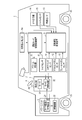
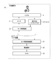
- FIG. 1 is a diagram showing an overall configuration of an automatic operation control system including an operation mode switching control device according to an embodiment of the present invention.
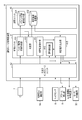
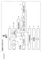
- FIG. 2 is a block diagram showing a functional configuration of the operation mode switching control device according to the embodiment of the present invention.
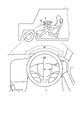
- FIG. 3 is a schematic diagram for explaining a handle operation by the operation mode switching control device shown in FIG.
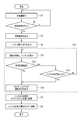
- FIG. 4 is a flowchart showing the procedure and control contents of the operation mode switching control by the operation mode switching control device shown in FIG.
- FIG. 5 is a block diagram showing a functional configuration related to step S1 in the flow shown in FIG.
- FIG. 6 is a block diagram showing a functional configuration related to steps S2 to S6 and S10 in the flow shown in FIG.
- FIG. 7 is a time chart showing an operation mode and a linked state corresponding to each step of the flow shown in FIG.
- FIG. 1 is a diagram showing an overall configuration of an automatic operation control system including an operation mode switching control device according to an embodiment of the present invention.
- This automatic driving control system is mounted on a vehicle 1 such as a passenger car.
- the vehicle 1 includes, as basic equipment, a power unit 2 including a power source (not shown), a tire drive control device 21 and a drive mechanism 22, and a steering device 3 equipped with a handle 4 that can rotate around a rotation axis AX.
- the vehicle 1 has a manual operation mode and an automatic operation mode as operation modes.
- An engine and / or a motor is used as the power source.
- the tire drive control device 21 controls the drive mechanism 22 and the motor control device 32 based on the detection signals of the sensors 8 and 11 to 13 that detect the driving operation and the control signal from the automatic driving control device 5.
- the drive mechanism 22 is controlled by the tire drive control device 21 to drive the tire 23.
- a driving method any method such as front wheel driving, rear wheel driving, or four wheel driving can be used as appropriate.
- the steering device 3 includes a motor 31 for controlling the operation of the handle 4 and a motor control device 32 for controlling the motor 31. Further, the steering device 3 causes the motor 31 and the motor control device 32 to operate the handle 4 independently of the direction of the tire 23 by releasing the linkage and the function of interlocking the rotational position of the handle 4 with the direction of the tire 23. It has a function.
- the motor control device 32 controls the motor 31 based on detection signals from the sensors 8 and 11 that detect the steering wheel state, tire state information received from the tire drive control device 21, and instructions received from the operation mode switching control device 6. . Note that the motor control device 32 can also control the motor 31 based on the tire condition information received from the automatic operation control device 5 instead of the tire condition information received from the tire drive control device 21 during automatic operation.
- the vehicle 1 will be described by taking as an example the case of using steer-by-wire control in which the steering wheel 4 and the tire 23 are interlocked with each other via an electrical signal.
- the vehicle 1 is not necessarily limited to steer-by-wire control.
- “steering wheel” may be read as “steering wheel”.
- the manual driving mode is a mode in which the vehicle 1 is driven mainly by a driver's manual driving operation, for example.
- the manual operation mode includes, for example, an operation mode for driving the vehicle based only on the driver's driving operation, and an operation mode for performing driving operation support control for supporting the driving operation of the driver while mainly driving the driver's driving operation. Is included.
- the driving operation support control assists the steering torque so that the driver's steering becomes an appropriate steering amount based on the curvature of the curve when the vehicle 1 is traveling on the curve, for example.
- the driving operation support control includes control for assisting a driver's accelerator operation (for example, operation of an accelerator pedal) or brake operation (for example, operation of a brake pedal), manual steering (manual operation of steering), and manual speed adjustment (speed). Adjustment manual operation).
- a driver's accelerator operation for example, operation of an accelerator pedal
- brake operation for example, operation of a brake pedal
- manual steering manual operation of steering
- speed speed adjustment
- Adjustment manual operation In manual steering, the vehicle 1 is steered mainly by the operation of the driver's handle 4.
- the speed of the vehicle is adjusted mainly by the driver's accelerator operation or brake operation.
- the driving operation support control does not include control for forcibly intervening in the driving operation of the driver and automatically driving the vehicle.
- the driving operation of the driver is reflected in the driving of the vehicle within a preset allowable range, but forcibly intervenes in the driving of the vehicle under certain conditions (for example, deviation from the lane of the vehicle). Control to do is not included.
- the automatic operation mode is a mode that realizes an operation state in which the vehicle automatically travels along the road on which the vehicle travels, for example.
- the automatic driving mode includes, for example, a driving state in which the vehicle automatically travels toward a preset destination without driving by the driver.
- the automatic driving mode does not necessarily need to automatically perform all the control of the vehicle, and includes a driving state in which the driving operation of the driver is reflected in the traveling of the vehicle within a preset allowable range. That is, the automatic driving mode includes control for forcibly intervening in driving of the vehicle under certain conditions, while reflecting the driving operation of the driver in driving of the vehicle within a preset allowable range.
- the automatic operation control device 5 performs operation control in the automatic operation mode.
- the automatic driving control device 5 acquires sensing data from the steering sensor 11, the accelerator pedal sensor 12, the brake pedal sensor 13, the GPS receiver 14, the gyro sensor 15, and the vehicle speed sensor 16, respectively.
- the automatic driving control device 5 monitors these sensing data, route information generated by a navigation system (not shown), traffic information acquired by road-to-vehicle communication, and the positions and movements of surrounding people and vehicles.
- the travel of the vehicle 1 is automatically controlled based on information obtained by the monitoring system.
- Automatic control includes, for example, automatic steering (automatic steering operation) and automatic speed adjustment (automatic driving of speed).
- Automatic steering is an operating state in which the steering device 3 is automatically controlled.
- Automatic steering includes Lane Keeping Assist (LKA).
- LKA Lane Keeping Assist
- the LKA automatically controls the steering device 3 so that the vehicle 1 does not deviate from the traveling lane even when the driver does not operate the steering wheel.
- the steering operation of the driver may be reflected in the steering of the vehicle in a range (allowable range) in which the vehicle 1 does not depart from the travel lane.
- automatic steering is not limited to LKA.
- “steering operation” may be read as “steering operation”.
- Automatic speed adjustment is an operating state in which the speed of the vehicle 1 is automatically controlled.
- Automatic speed adjustment includes Adaptive Cruise Control (ACC). For example, when there is no preceding vehicle ahead of the vehicle 1, ACC performs constant speed control that causes the vehicle 1 to travel at a constant speed at a preset speed, and when the preceding vehicle exists ahead of the vehicle 1. Is a follow-up control that adjusts the vehicle speed of the vehicle 1 in accordance with the inter-vehicle distance from the preceding vehicle.
- the automatic operation control device 5 decelerates the vehicle 1 according to the driver's brake operation (for example, operation of the brake pedal) even when ACC is being executed.
- the automatic operation control device 5 can perform the driver's accelerator operation (for example, accelerator) up to a preset maximum allowable speed (for example, the maximum speed legally determined on the traveling road) even during execution of ACC.
- the vehicle can be accelerated according to the pedal operation.
- the automatic speed adjustment is not limited to ACC, but also includes Cruise Control (CC) that performs only constant speed control.
- CC Cruise Control
- the automatic operation control system of one embodiment is a device for switching the operation mode of the vehicle 1 between the manual operation mode and the automatic operation mode, as a switching request detection unit 6a, an operation mode switching control device 6, A driver camera 7 as a first monitoring sensor, a torque sensor 8 as a second monitoring sensor, and an alarm generator 9 are provided.
- the switching request detection unit 6a When the switching request detection unit 6a detects a switching request for switching the manual operation mode to the automatic operation mode, the switching request detection unit 6a inputs the switching request to the operation mode switching control device 6.
- the switching request detection unit 6a for example, a switching switch and a voice recognition device can be used as appropriate.
- the switching request operation by the driver or the voice input of the switching request is detected as a switching request, and the switching request is driven. Input to the mode switching control device 6.
- the changeover switch as an example of the change request detection unit 6a may be implemented as a push button provided on the handle 4, a soft button provided on the touch panel, or the like.
- the driver camera 7 is installed, for example, at a position in front of the driver as on the dashboard, and images the driver and outputs a video signal thereof to the driving mode switching control device 6.
- the torque sensor 8 detects torque generated when the driver operates the steering wheel 4, and outputs a detection signal to the driving mode switching control device 6, the tire drive control device 21, and the motor control device 32.
- the alarm generator 9 includes a speaker and a display. The alarm generator 9 outputs the voice signal of the message output from the operation mode switching control device 6 from the speaker and displays the display signal of the message on the display.
- the operation mode switching control device 6 controls the switching of the operation modes as a whole, and is configured as follows.
- FIG. 2 is a block diagram showing the functional configuration.
- the operation mode switching control device 6 includes a control unit 61, an input / output interface unit 62, and a storage unit 63.
- the input / output interface unit 62 receives the video signal and the torque detection signal output from the driver camera 7 and the torque sensor 8, respectively, and converts them into digital data. Similarly, the input / output interface unit 62 receives detection signals as sensing data output from the steering sensor 11, the accelerator pedal sensor 12, and the brake pedal sensor 13, and converts them into digital data. The input / output interface unit 62 receives the switching request input from the switching request detection unit 6a. The input / output interface unit 62 converts the message output from the control unit 61 into an audio signal and a display signal, and outputs them to the alarm generator 9. Further, the input / output interface unit 62 outputs the switching signal output from the control unit 61 to the automatic operation control device 5.
- the storage unit 63 uses a non-volatile memory such as Solid ⁇ ⁇ ⁇ State Drive (SSD) and Hard Disk Drive (HDD) that can be written and read at any time, or a volatile memory such as Random Access Memory (RAM) as a storage medium.
- the storage unit 63 includes a driver monitoring video storage unit 631 and a determination result storage unit 632 as storage areas used for carrying out one embodiment.
- the control unit 61 has a central processing unit (CPU) and a program memory that constitute a computer.
- the control unit 61 includes a driver monitoring video acquisition unit 611, a determination unit 612, an operation detection unit 613, a switching request reception unit 614, and a switching signal output unit 615 as control functions necessary for carrying out one embodiment. And.
- Each of these control functions is realized by causing the CPU to execute a program stored in the program memory.
- the driver monitoring video acquisition unit 611 receives digital data (driver monitoring video data) of the driver video signal output from the driver camera 7 from the input / output interface unit 62, and stores the acquired driver monitoring video data in the storage unit 63. Are stored in the driver monitoring video storage unit 631.
- the determination unit 612 reads the driver monitoring video data from the driver monitoring video storage unit 631 at a preset time interval. Then, each time the driver monitoring video data is read, the determination unit 612 performs a process of determining whether or not the driver can manually perform a driving operation based on the driver monitoring video data. For example, the determination unit 612 determines whether or not the driver is in a sleep state by checking whether or not the driver has closed his / her eyes. Then, the determination unit 612 stores information indicating the determination result in the determination result storage unit 632 in association with a time stamp indicating the determination timing.
- a process of detecting a driver's eye open state, blinking frequency, or eye movement based on driver monitoring video data and recognizing the driver's arousal level May be included.
- This arousal level is an example of the degree of concentration and is represented by a numerical value within a range of 0 to 100%.
- the degree of concentration is not limited to a numerical value within the range of 0 to 100%.
- “1” is set when the driver's line-of-sight direction is within a predetermined range
- “0” is set when the driver is not within the predetermined range.
- a value (flag) of “1” or “0” may be used.
- the determination unit 612 may perform determination processing for determining whether or not the driver has released the handle 4 based on the driver video monitoring data stored in the driver monitoring video storage unit 631. As this determination, for example, the state of the driver's hand and the handle 4 are detected based on the driver monitoring video data, and it is determined whether or not the driver's hand image and the handle 4 image overlap. Good. Note that the determination unit 612 may perform determination processing for determining whether or not the driver has released the handle 4 based on the detection signal of the torque sensor 8 or the steering sensor 11 instead of the driver video monitoring data. Good.
- the operation detection unit 613 detects an override operation by the driver based on a detection signal output from the torque sensor 8 as an in-vehicle sensor capable of detecting a driving operation by the driver.
- a detection signal output from the torque sensor 8 as an in-vehicle sensor capable of detecting a driving operation by the driver.
- the steering sensor 11, the accelerator pedal sensor 12, and the brake pedal sensor 13 can be used suitably.
- the operation detection unit 613 may detect an override operation during a period in which the handle 4 is interlocked with the direction of the tire 23 in the operation control period in the automatic operation mode. On the other hand, the operation detection unit 613 does not have to detect the override operation during the period in which the linkage between the tire 23 and the handle 4 is released during the operation control period in the automatic operation mode. In any case, the second switching signal for switching the automatic operation mode to the manual operation mode may not be output from the switching signal output unit 615 during the period when the interlock is released.
- Such an operation detection unit 613 may be provided in the automatic operation control device 5 instead of the configuration provided in the operation mode switching control device 6.
- the switching request reception unit 614 When the switching request reception unit 614 receives the switching request output from the switching request detection unit 6a and switches the manual operation mode to the automatic operation mode, the switching request reception unit 614 outputs the switching request to the switching signal output unit 615.
- the switching request receiving unit 614 may hold the received switching request in a storage unit (not shown).
- the switching signal output unit 615 generates a first switching signal for switching the manual operation mode to the automatic operation mode based on the switching request received by the switching request receiving unit 614 (or the switching request held in the storage unit). 5 and outputs a handle operation instruction for operating the handle independently of the tire direction to the motor control device 32 by releasing the linkage between the handle of the vehicle 1 and the tire.
- the steering wheel operation instruction may include an instruction to cancel the interlocking with respect to the steer-by-wire control that interlocks the steering wheel 4 and the tire 23 via an electrical signal.
- the motor control device 32 that has received the steering wheel operation instruction in a state where the automatic driving control device 5 that has received the first switching signal has started automatic driving.
- the linkage between the handle 4 and the tire 23 is released, and the handle 4 is operated independently of the direction of the tire 23.
- the switching signal output unit 615 may execute the following processes (1) and (2).
- the interlock instruction may be output even before a predetermined time has elapsed.
- the interlocking instruction may be an instruction for interlocking the handle 4 and the tire 23 after moving the rotational position of the handle 4 to a position corresponding to the direction of the tire 23.
- the handle operation instruction as shown in FIG. 3, for example, (a) a vibration operation for vibrating the handle 4, (b) a rotation operation M1 for rotating the handle 4 about the rotation axis AX, (c One of a tilting operation M2 for tilting the handle 4 along the vertical direction, and (d) a retracting operation M3 for pulling the handle 4 to the vehicle 1 side (side away from the driver) along the rotation axis AX.
- An instruction for causing the vehicle 1 to perform the operation may be included.
- the vibration operation may be an operation in which each of the operations M1 to M3 is executed with a shorter cycle than the original operations M1 to M3.
- the handle 4 may be vibrated by the motor 31, or a vibrator may be provided in the handle 4 separately from the motor 31, and the handle 4 may be vibrated by the vibrator.
- the tilt operation M2 uses the lower direction of the arrow in FIG. 3, and the upper direction indicates an operation when returning by an interlocking instruction.
- the pull-in operation M3 uses the direction of the diagonally lower left side of the arrow in FIG. 3, and the direction of the diagonally upper right side indicates an operation when returning by an interlocking instruction.
- An override process that outputs a signal to the automatic operation control device 5 and does not output a second switching signal when an override operation is detected during a period in which the interlock is released.
- the determination result by the determination unit 612 immediately before the override operation is detected is a state in which the driving operation can be performed.
- the second switching signal may be output to the automatic operation control device 5 when the condition of indicating is satisfied.
- FIG. 4 is a flowchart showing the overall control procedure and control contents
- FIGS. 5 and 6 are block diagrams showing functional configurations related to this flow.
- FIG. 7 is a time chart showing an operation mode and an interlocking state corresponding to each step of this flow.
- the driver monitoring video acquisition unit 611 stores the driver monitoring video data output from the driver camera 7 in the driver monitoring video storage unit 631. Further, each time the driver monitoring video data is read from the driver monitoring video storage unit 631 at a preset time interval, the determination unit 612 is set in a state in which the driver can manually perform a driving operation based on the driver monitoring video data.
- a process for determining whether or not there is a process and a process for determining whether or not the driver has released the handle 4 are performed.
- the determination unit 612 stores information indicating the determination result in the determination result storage unit 632 in association with a time stamp indicating the determination timing.
- the rotational position of the handle 4 and the direction of the tire 23 are linked via an electric signal in accordance with the driving operation of the driver during the manual driving period in the manual driving mode in step S ⁇ b> 1.
- Manual operation is performed using steer-by-wire control.
- the sensors 8, 11 to 13 detect the state of the handle 4 and the like, and output detection signals to the tire drive control device 21.
- the tire drive control device 21 controls the direction and rotational speed of the tire 23 via the drive mechanism 22 based on each detection signal.
- the tire drive control device 21 outputs tire state information indicating the direction of the tire 23 to the motor control device 32.
- the motor control device 32 controls the rotational position of the handle 4 via the motor 31 based on the tire condition information.
- the operation mode switching control device 6 switches the switching request for switching the manual operation mode to the automatic operation mode in step S ⁇ b> 2 under the control of the switching request receiving unit 614.
- the output switching request is accepted.
- the switching request receiving unit 614 outputs the received switching request to the switching signal output unit 615.
- step S4 switching signal output to automatic driving
- the switching signal output unit 615 automatically generates a first switching signal for switching the manual driving mode to the automatic driving mode based on the switching request received by the switching request receiving unit 614 in step S3. Output to the operation control device 5.
- the automatic operation control device 5 ends the manual operation mode, and thereafter, operation control in the automatic operation mode is performed.
- processing such as the following step S4 is executed in order to make the driver feel that the mode has been switched to the automatic operation mode. That is, in step S4, the switching signal output unit 615 releases the linkage between the handle 4 of the vehicle 1 and the tire 23 and operates the handle 4 independently of the direction of the tire 23 based on the switching request.
- An instruction is output to the motor control device 32.
- This handle operation instruction includes an instruction to release the interlock for the steer-by-wire control that interlocks the handle 4 and the tire 23 via an electrical signal.
- step S10 including steps S11 to S14 under the control of the switching signal output unit 615.
- the switching signal output unit 615 stops the interlock control of the motor 31 by the motor control device 32 and outputs the handle operation instruction to the motor control device 32, and controls the handle operation of the motor 31 by the motor control device 32. .
- the motor control device 32 releases the interlock between the handle 4 and the tire 23 and operates the handle 4 independently of the direction of the tire 23 (step S11). For this reason, the handle 4 operates so as to vibrate at the current position, for example.
- the handle 4 moves from the current rotational position (eg, the top is at the 12 o'clock position) and reciprocates between any two rotational positions (eg, the top is at the 10 o'clock position and the 2 o'clock position). To work.
- the handle 4 operates to move to an inclined position or a retracted position.
- the switching signal output unit 615 is operable even when an override operation is detected by the operation detection unit 613 during a period in which the linkage between the handle 4 and the tire 23 is released during the operation control period in the automatic operation mode.
- the second switching signal for switching the automatic operation mode to the manual operation mode is not output.
- the driver can feel that the operation mode has been switched to the automatic operation mode without performing aside driving by sensing the operation of the handle 4 while holding the handle 4.
- the switching signal output unit 615 determines whether or not a predetermined time has elapsed after the output of the steering operation instruction (step S12). When the predetermined time has elapsed, the process proceeds to step S14. If the predetermined time has not elapsed, it is determined whether or not the determination result by the determination unit 612 indicates that the handle 4 has been released (step S13), and if the handle has been released, the predetermined time has elapsed. Even before the process proceeds to step S14. If the handle is held, the process returns to step S11.
- step S14 the switching signal output unit 615 outputs an interlocking instruction for interlocking the handle 4 of the vehicle 1 and the tire 23 to the motor control device 32.
- This interlocking instruction is an instruction to interlock the handle 4 and the tire 23 after moving the position of the handle 4 to a position corresponding to the direction of the tire 23.
- the switching signal output unit 615 restarts the interlock control of the motor 31 by the motor control device 32 by outputting the interlock instruction to the motor control device 32.
- the motor control device 32 Upon receiving this interlocking instruction, the motor control device 32 interlocks and controls the motor 31 based on the tire condition information received from the tire drive control device 21 and moves the rotational position of the handle 4 to a position corresponding to the direction of the tire 23. (Step S5). Thereafter, the motor control device 32 controls the motor 31 based on the tire condition information, and links the rotational position of the handle 4 with the direction of the tire 23 (step S6).
- step S6 the switching operation from the manual operation mode to the automatic operation mode as described above is performed when the handle 4 and the tire 23 are interlocked (steps S1 and S2), and when the mode is switched (step S3).
- step S10 the state including no steering operation including the steering wheel operation independent from the tire 23 (step S10), the alignment state of rotating the steering wheel 4 (step S5), and the state of interlocking (step S6) are completed. .
- the operation detection unit 613 detects an override operation by the driver based on, for example, a detection signal output from the torque sensor 8.
- the switching signal output unit 615 indicates that the determination result by the determination unit 612 immediately before the override operation is detected indicates a state in which the driving operation can be performed. Determine whether the condition is met.
- the switching signal output unit 615 outputs a second switching signal for switching the automatic operation mode to the manual operation mode to the automatic operation control device 5.
- the automatic driving control device 5 ends the automatic driving mode, and thereafter, driving control according to the manual operation of the driver is performed.
- a switching request for switching the manual operation mode to the automatic operation mode is accepted, and a first switching signal for switching the manual operation mode to the automatic operation mode is output based on the switching request. Then, the interlock of the vehicle handle 4 and the tire 23 is released, and a handle operation instruction for operating the handle 4 independently of the direction of the tire 23 is output. For this reason, after switching to the automatic driving mode, the driver can feel the switching to the automatic driving mode by operating the handle 4 and detecting the steering operation by the driver. Further, since the tire 23 is not interlocked with the steering operation, the automatic operation mode is not switched to the manual operation mode.
- an interlocking instruction for interlocking the steering wheel 4 and the tire 23 of the vehicle 1 is output.
- the steering wheel 4 and the tire 23 can be interlocked after the driver feels switching to the automatic driving mode. Therefore, when an override operation is performed during automatic driving after interlocking, it is possible to switch to the manual driving mode at an appropriate handle position interlocked with the tire 23.
- any of (a) handle vibration operation, (b) handle rotation operation, (c) handle tilt operation, and (d) handle pull-in operation is performed. For this reason, since the driver senses the steering wheel operation while holding the steering wheel without looking aside in the vehicle or the like, the switching to the automatic driving mode can be realized in a safe state.
- the override operation by the driver is detected based on the detection signal output from the in-vehicle sensor that can detect the driving operation by the driver.
- a second switching signal for switching the automatic driving mode to the manual driving mode is output. If an override operation is detected during the period when the interlock is released, the second switching signal is not output. For this reason, by operating the handle 4 during the interlock release period after switching to the automatic driving mode, the driver can feel the switching to the automatic driving mode. Further, even if an override operation due to the operation of the steering wheel is detected during the interlock release period, the second switching signal for switching to the manual operation mode is not output.
- the interlocking instruction is output even before a predetermined time has elapsed. For this reason, when the driver realizes switching to the automatic driving mode as soon as possible, the steering wheel 4 and the tire 23 can be interlocked without waiting for the elapse of a predetermined time.
- the handle 4 and the tire 23 are interlocked after the position of the handle 4 after being operated by the handle operation instruction is moved to a position corresponding to the direction of the tire 23 by the interlock instruction. For this reason, when shifting from the interlock release state to the interlock state, the rotational position of the handle 4 can be brought close to a position corresponding to the direction of the tire 23.
- the interlocking is released with respect to the steer-by-wire control in which the steering wheel 4 and the tire 23 are interlocked via an electrical signal. Therefore, it can be mounted on a steer-by-wire control vehicle.
- step S13 shown in FIG. 4 may be omitted, and if the determination result in step S12 is negative, the process may be modified to return to step S11.
- the vehicle 1 is not limited to the steer-by-wire configuration in which the steering wheel 4 and the tire 23 are electrically linked or released via an electrical signal, and the steering wheel 4 and the tire 23 are coupled via a shaft and a clutch. It is good also as a structure which cancels
- the vibration operation according to the embodiment has been described with respect to the case where the handle 4 is vibrated by the motor 31, but is not limited thereto.
- a vibrator is provided in the handle 4 separately from the motor 31, and 4 may be vibrated.
- the switching signal output unit 615 outputs a handle operation instruction to the motor control device 32.
- the switching signal output unit 615 may output a handle operation instruction to the automatic operation control device 5, and the automatic operation control device 5 may output the handle operation instruction to the motor control device 32. That is, the switching signal output unit 615 may output a handle operation instruction to the motor control device 32 via the automatic operation control device 5.
- the switching signal output unit 615 may output the interlock instruction to the automatic operation control device 5, and the automatic operation control device 5 may output the interlock instruction to the motor control device 32. That is, the switching signal output unit 615 may output the interlock instruction to the motor control device 32 via the automatic operation control device 5.
- step S5 of the embodiment the case where the motor control device 32 controls the motor 31 based on the tire state information received from the tire drive control device 21 has been described.
- the present invention is not limited to this.
- the motor 31 may be linked and controlled based on the tire condition information received from the automatic operation control device 5 by the motor control device 32.
- the switching signal output unit 615 does not output the second switching signal for switching the automatic operation mode to the manual operation mode immediately after switching to the automatic operation mode.
- 613 may be modified to a configuration in which an override operation is not detected within a predetermined time immediately after switching to the automatic operation mode. That is, if the operation detection unit 613 does not detect the override operation within a predetermined time immediately after switching to the automatic operation mode, the switching signal output unit 615 does not output the second switching signal during the predetermined period. Even in such a modification, the driver can feel the switching to the automatic operation mode while preventing the switching to the manual operation mode, as in the case of the embodiment.
- the vehicle type, the function of the automatic operation control device, the control function and control procedure of the operation mode switching control device, and the control contents can be variously modified and implemented without departing from the gist of the present invention.
- the present invention is not limited to the above-described embodiment as it is, and various modifications can be made without departing from the scope of the invention in the implementation stage.
- the embodiments may be appropriately combined as much as possible, and in that case, the combined effect can be obtained.
- various inventions can be extracted by an appropriate combination of a plurality of constituent elements disclosed in the one embodiment.
- An operation mode switching control device for switching a vehicle operation mode between a manual operation mode and an automatic operation mode, A memory for storing a switching request for switching the manual operation mode to the automatic operation mode; And at least one hardware processor connected to the memory, The at least one hardware processor comprises: Receiving the input of the switching request and storing it in a memory; Based on the switching request stored in the memory, a first switching signal for switching the manual driving mode to the automatic driving mode is output, and the linkage between the steering wheel of the vehicle and the tire is released to change the direction of the tire.
- Is an operation mode switching control device configured to output a handle operation instruction to operate the handle independently.
- An operation mode switching control method comprising: a switching signal output step of outputting a steering wheel operation instruction for releasing the interlock and operating the steering wheel independently of the tire direction.
Abstract
The present invention presents the following countermeasure, with the purpose of preventing switching to a manual driving mode and allowing a driver to sense a switch to an automatic driving mode. When switching a driving mode of a vehicle between a manual driving mode and an automatic driving mode, this driving mode switching control device receives a switching request to switch the manual driving mode to the automatic driving mode. On the basis of the received switching request, the driving mode switching control device outputs a first switching signal to switch the manual driving mode to the automatic driving mode, and outputs steering wheel operation instructions to disengage a link between a steering wheel and tires of the vehicle and cause the steering wheel to operate independently from the orientation of the tires.
Description
この発明は、車両の運転モードを手動運転モードと自動運転モードとの間で切り替えるための運転モード切替制御装置、方法およびプログラムに関する。
The present invention relates to an operation mode switching control device, method and program for switching a vehicle operation mode between a manual operation mode and an automatic operation mode.
近年、車両の運転モードとして、運転者の運転操作に基づいて車両を走行させる手動運転モード以外に、運転者の運転操作によらず予め設定された経路に沿って車両を走行させる自動運転モードの開発が進められている。自動運転モードは、例えば、Global Positioning System(GPS)を利用したナビゲーションシステムの情報や、路車間通信により取得される交通情報、周辺の人や車両の位置と動きを監視する周辺モニタリングシステムの情報をもとに、パワーユニットや操舵装置(例えば、特開2016-210220号公報、特開2016-132264号公報および特開2016-199081号公報を参照)、ブレーキ等を制御することで、車両の自動運転を可能にするものである。
In recent years, as a driving mode of a vehicle, in addition to a manual driving mode in which the vehicle is driven based on a driving operation of the driver, an automatic driving mode in which the vehicle is driven along a predetermined route without depending on the driving operation of the driver. Development is underway. Autonomous driving mode includes, for example, navigation system information using the Global Positioning System (GPS), traffic information acquired by road-to-vehicle communication, and information on the surrounding monitoring system that monitors the position and movement of people and vehicles in the vicinity. Based on the power unit and the steering device (see, for example, Japanese Patent Application Laid-Open Nos. 2016-210220, 2016-132264, and 2016-199081), the automatic operation of the vehicle, etc. Is possible.
このような自動運転モードでは、手動運転モードからの切り替え後に、運転者がハンドル等の操作を終了することが可能となり、運転者の運転操作の負担を軽減させている。また、自動運転モードは、自動運転中に運転者による運転操作(以下、オーバーライド操作という)があれば、運転者の状態確認の後、手動運転モードに切り替えられる。
In such an automatic operation mode, it becomes possible for the driver to finish the operation of the steering wheel and the like after switching from the manual operation mode, thereby reducing the burden of the driver's operation operation. Further, the automatic operation mode is switched to the manual operation mode after confirming the state of the driver if there is a driving operation by the driver (hereinafter referred to as an override operation) during the automatic driving.
ところが、以上のような自動運転モードを用いた自動運転は、本発明者の検討によれば、運転者の意識を考慮していない点で改善の余地がある。
However, the automatic driving using the automatic driving mode as described above has room for improvement in that the driver's consciousness is not considered according to the study of the present inventors.
例えば、手動運転モードから自動運転モードに切り替わった直後には、運転者が手動運転と同様にハンドルを把持しており、手動運転と同じ感覚でハンドル操作を行う可能性がある。これは、運転者にはハンドルを手放すことに心理的な抵抗があり、自動運転モードに切り替わったことを実感してからハンドル操作を終了したい意識があるためである。
For example, immediately after switching from the manual operation mode to the automatic operation mode, the driver holds the handle in the same manner as in the manual operation, and there is a possibility that the handle operation is performed in the same manner as in the manual operation. This is because the driver has psychological resistance to let go of the steering wheel and is conscious of ending the steering operation after realizing that the driver has switched to the automatic driving mode.
しかしながら、このような運転者の意識とは別に、自動運転中の運転者によるハンドル操作は、オーバーライド操作として検出されるので、自動運転モードが手動運転モードに切り替えられてしまう。
However, in addition to the driver's awareness, the steering operation by the driver during automatic driving is detected as an override operation, so the automatic driving mode is switched to the manual driving mode.
この発明は、手動運転モードへの切り替えを阻止しつつ、自動運転モードへの切り替えを運転者が実感できるようにした運転モード切替制御装置、方法およびプログラムを提供しようとするものである。
This invention is intended to provide an operation mode switching control device, method, and program that allow the driver to realize the switching to the automatic operation mode while preventing the switching to the manual operation mode.
上記課題を解決するためにこの発明の第1の態様は、車両の運転モードを手動運転モードから自動運転モードへ切り替えるための運転モード切替制御装置であって、前記手動運転モードを前記自動運転モードに切り替える切替要求を受け付ける切替要求受付部と、前記切替要求受付部により受け付けた前記切替要求に基づいて、前記手動運転モードを前記自動運転モードに切り替える第1切替信号を出力し、前記車両のハンドルとタイヤとの連動を解除して前記タイヤの向きとは独立に前記ハンドルを動作させるハンドル動作指示を出力する切替信号出力部とを具備するようにしたものである。
In order to solve the above problems, a first aspect of the present invention is an operation mode switching control device for switching a vehicle operation mode from a manual operation mode to an automatic operation mode, wherein the manual operation mode is changed to the automatic operation mode. A switching request receiving unit for receiving a switching request to switch to the vehicle, and a first switching signal for switching the manual driving mode to the automatic driving mode based on the switching request received by the switching request receiving unit. And a switching signal output unit that outputs a steering operation instruction for operating the steering wheel independently of the tire direction by releasing the linkage between the tire and the tire.
この発明の第1の態様によれば、手動運転モードを自動運転モードに切り替える切替要求が受け付けられ、切替要求に基づいて、手動運転モードを自動運転モードに切り替える第1切替信号が出力され、車両のハンドルとタイヤとの連動を解除してタイヤの向きとは独立にハンドルを動作させるハンドル動作指示が出力される。このため、自動運転モードへの切り替え後に、ハンドルが動作して当該ハンドル動作を運転者が感知することにより、自動運転モードへの切り替えを運転者が実感できる。また、ハンドル操作にタイヤが連動しないため、自動運転モードから手動運転モードへの切り替えが行われない。
According to the first aspect of the present invention, a switching request for switching the manual operation mode to the automatic operation mode is accepted, and a first switching signal for switching the manual operation mode to the automatic operation mode is output based on the switching request, and the vehicle A handle operation instruction for releasing the interlock between the handle and the tire and operating the handle independently of the direction of the tire is output. For this reason, after switching to the automatic driving mode, the driver can feel the switching to the automatic driving mode by operating the steering wheel and detecting the steering operation by the driver. Further, since the tire is not interlocked with the steering wheel operation, the automatic operation mode is not switched to the manual operation mode.
この発明の第2の態様は、前記切替信号出力部が指示出力部を備え、前記指示出力部により、前記ハンドル動作指示の出力後、所定時間が経過すると、前記車両のハンドルとタイヤとを連動させる連動指示を出力するようにしたものである。
According to a second aspect of the present invention, the switching signal output unit includes an instruction output unit, and when a predetermined time has elapsed after the steering operation instruction is output by the instruction output unit, the vehicle handle and the tire are interlocked. The interlock instruction to be output is output.
この発明の第2の態様によれば、ハンドル動作指示の出力後、所定時間が経過すると、車両のハンドルとタイヤとを連動させる連動指示が出力される。これにより、運転者に自動運転モードへの切り替えを実感させた後、ハンドルとタイヤを連動させることができる。従って、連動後の自動運転中にオーバーライド操作が行われた場合に、タイヤと連動した適切なハンドル位置で手動運転モードに切り替えることができる。
According to the second aspect of the present invention, when a predetermined time elapses after the steering wheel operation instruction is output, the interlocking instruction for interlocking the vehicle steering wheel and the tire is output. As a result, the steering wheel and the tire can be interlocked after the driver is made to realize the switching to the automatic driving mode. Therefore, when an override operation is performed during automatic driving after interlocking, it is possible to switch to the manual driving mode at an appropriate handle position interlocked with the tire.
この発明の第3の態様は、前記ハンドル動作指示が、(a)前記ハンドルを振動させる振動動作、(b)前記ハンドルを回転軸を中心に回動させる回動動作、(c)前記ハンドルを上下方向に沿って傾けるチルト動作、および(d)前記ハンドルを前記回転軸に沿って前記車両側に引き込む引込動作、のうちのいずれかの動作を前記車両に行わせる指示を含むようにしたものである。
According to a third aspect of the present invention, the handle operation instruction includes: (a) a vibration operation that vibrates the handle; (b) a rotation operation that rotates the handle around a rotation axis; and (c) the handle. An instruction for causing the vehicle to perform any one of a tilting operation for tilting along the vertical direction and (d) a retraction operation for pulling the handle toward the vehicle along the rotation axis. It is.
この発明の第3の態様によれば、ハンドル動作指示により、(a)ハンドルの振動動作、(b)ハンドルの回動動作、(c)ハンドルのチルト動作、および(d)ハンドルの引込動作のいずれかが行われる。このため、運転者が車内などの脇見をすることなく、ハンドルを把持した状態でハンドル動作を感知するので、安全な状態で自動運転モードへの切り替えを実感することができる。
According to the third aspect of the present invention, in response to the handle operation instruction, (a) the vibration operation of the handle, (b) the rotation operation of the handle, (c) the tilt operation of the handle, and (d) the retracting operation of the handle. One is done. For this reason, since the driver senses the steering wheel operation while holding the steering wheel without looking aside in the vehicle or the like, the switching to the automatic driving mode can be realized in a safe state.
この発明の第4の態様は、運転者による運転操作を検出可能な車載センサから出力された検出信号に基づいて、前記運転者によるオーバーライド操作を検出する操作検出部をさらに具備し、前記切替信号出力部がオーバーライド処理部を備え、前記オーバーライド処理部により、前記自動運転モードによる運転制御期間のうち前記ハンドルと前記タイヤとが連動する期間中に前記操作検出部により前記オーバーライド操作が検出された場合には前記自動運転モードを前記手動運転モードに切り替える第2切替信号を出力し、前記連動が解除された期間中に前記オーバーライド操作が検出された場合には前記第2切替信号を出力しないようにしたものである。
A fourth aspect of the present invention further includes an operation detection unit that detects an override operation by the driver based on a detection signal output from an in-vehicle sensor capable of detecting a driving operation by the driver, and the switching signal When the output unit includes an override processing unit, and the override processing unit detects the override operation by the operation detection unit during a period in which the steering wheel and the tire are interlocked during the driving control period in the automatic driving mode. Outputs a second switching signal for switching the automatic operation mode to the manual operation mode, and does not output the second switching signal when the override operation is detected during the period when the interlock is released. It is a thing.
この発明の第4の態様によれば、運転者による運転操作を検出可能な車載センサから出力された検出信号に基づいて、運転者によるオーバーライド操作が検出される。自動運転モードによる運転制御期間のうちハンドルとタイヤとが連動する期間中にオーバーライド操作が検出された場合には自動運転モードを手動運転モードに切り替える第2切替信号が出力される。連動が解除された期間中にオーバーライド操作が検出された場合には第2切替信号が出力されない。このため、自動運転モードへの切り替え後の連動解除期間中にハンドルを動作させることにより、自動運転モードへの切り替えを運転者が実感できる。また、連動解除期間中にハンドルの動作によるオーバーライド操作を検出しても手動運転モードに切り替える第2切替信号が出力されない。
According to the fourth aspect of the present invention, the override operation by the driver is detected based on the detection signal output from the vehicle-mounted sensor that can detect the driving operation by the driver. When an override operation is detected during a period in which the steering wheel and the tire are interlocked in the driving control period in the automatic driving mode, a second switching signal for switching the automatic driving mode to the manual driving mode is output. If an override operation is detected during the period when the interlock is released, the second switching signal is not output. For this reason, by operating the steering wheel during the interlock release period after switching to the automatic driving mode, the driver can realize switching to the automatic driving mode. Further, even if an override operation due to the operation of the steering wheel is detected during the interlock release period, the second switching signal for switching to the manual operation mode is not output.
この発明の第5の態様は、運転者が前記ハンドルを手放した状態か否かを判定する判定部とをさらに具備し、前記指示出力部により、前記判定部による判定結果が前記ハンドルを手放した状態を表す場合に、前記所定時間が経過する前でも前記連動指示を出力するようにしたものである。
The fifth aspect of the present invention further includes a determination unit that determines whether or not the driver has released the handle, and the determination result by the determination unit is released by the instruction output unit. In the case of representing a state, the interlocking instruction is output even before the predetermined time has elapsed.
この発明の第5の態様によれば、運転者がハンドルを手放した状態か否かが判定され、判定結果がハンドルを手放した状態を表す場合に、所定時間が経過する前でも連動指示が出力される。このため、早々に運転者が自動運転モードへの切り替えを実感した場合に、所定時間の経過を待つことなく、ハンドルとタイヤを連動させることができる。
According to the fifth aspect of the present invention, it is determined whether or not the driver has released the steering wheel, and when the determination result indicates the state of releasing the steering wheel, the interlock instruction is output even before the predetermined time has elapsed. Is done. For this reason, when the driver quickly realizes switching to the automatic driving mode, the steering wheel and the tire can be interlocked without waiting for the elapse of a predetermined time.
この発明の第6の態様は、前記連動指示としては、前記ハンドル動作指示により動作させた後の前記ハンドルの位置を前記タイヤの向きに応じた位置に移動させた後、前記ハンドルと前記タイヤとを連動させる指示であるようにしたものである。
According to a sixth aspect of the present invention, as the interlocking instruction, the position of the handle after being operated according to the handle operation instruction is moved to a position corresponding to the direction of the tire, and then the handle, the tire, This is an instruction to link the.
この発明の第6の態様によれば、連動指示により、ハンドル動作指示により動作させた後のハンドルの位置をタイヤの向きに応じた位置に移動させた後、ハンドルとタイヤとが連動される。このため、連動解除の状態から連動状態に移行する際に、ハンドルの回転位置をタイヤの向きに応じた位置に近づけることができる。
According to the sixth aspect of the present invention, the handle and the tire are interlocked after the position of the handle after being operated by the handle operation instruction is moved to a position corresponding to the direction of the tire by the interlock instruction. For this reason, when shifting from the interlock release state to the interlock state, the rotational position of the handle can be brought close to a position corresponding to the direction of the tire.
この発明の第7の態様は、前記ハンドル動作指示が、前記ハンドルと前記タイヤとの間を電気信号を介して連動させるステア・バイ・ワイヤ制御に対して前記連動を解除させる指示を含むようにしたものである。
According to a seventh aspect of the present invention, the steering operation instruction includes an instruction to release the interlocking with respect to steer-by-wire control that interlocks the steering wheel and the tire via an electrical signal. It is a thing.
この発明の第7の態様によれば、ハンドル動作指示により、ハンドルとタイヤとの間を電気信号を介して連動させるステア・バイ・ワイヤ制御に対して連動が解除される。このため、ステア・バイ・ワイヤ制御の車両に対して実装することができる。
According to the seventh aspect of the present invention, in response to the steering operation instruction, the interlock is released with respect to the steer-by-wire control in which the steering wheel and the tire are interlocked via an electrical signal. Therefore, it can be mounted on a steer-by-wire control vehicle.
すなわちこの発明の各態様によれば、手動運転モードへの切り替えを阻止しつつ、自動運転モードへの切り替えを運転者が実感できるようにした運転モード切替制御装置、方法およびプログラムを提供することができる。
That is, according to each aspect of the present invention, it is possible to provide an operation mode switching control device, a method, and a program that allow the driver to feel the switch to the automatic operation mode while preventing the switch to the manual operation mode. it can.
以下、図面を参照してこの発明に係わる実施形態を説明する。
[一実施形態]
図1は、この発明の一実施形態に係る運転モード切替制御装置を備えた自動運転制御システムの全体構成を示す図である。この自動運転制御システムは乗用車等の車両1に搭載される。 Embodiments according to the present invention will be described below with reference to the drawings.
[One Embodiment]
FIG. 1 is a diagram showing an overall configuration of an automatic operation control system including an operation mode switching control device according to an embodiment of the present invention. This automatic driving control system is mounted on avehicle 1 such as a passenger car.
[一実施形態]
図1は、この発明の一実施形態に係る運転モード切替制御装置を備えた自動運転制御システムの全体構成を示す図である。この自動運転制御システムは乗用車等の車両1に搭載される。 Embodiments according to the present invention will be described below with reference to the drawings.
[One Embodiment]
FIG. 1 is a diagram showing an overall configuration of an automatic operation control system including an operation mode switching control device according to an embodiment of the present invention. This automatic driving control system is mounted on a
車両1は、基本設備として、図示しない動力源、タイヤ駆動制御装置21および駆動機構22を含むパワーユニット2と、回転軸AXを中心に回転可能なハンドル4が装備された操舵装置3とを備える。また車両1は、運転モードとしては手動運転モードと自動運転モードとを備えている。動力源としては、エンジンまたはモータ、あるいはその両方が用いられる。タイヤ駆動制御装置21は、運転操作を検出する各センサ8、11~13の検出信号及び自動運転制御装置5からの制御信号に基づいて、駆動機構22及びモータ制御装置32を制御する。駆動機構22は、タイヤ駆動制御装置21に制御され、タイヤ23を駆動する。駆動方式としては、前輪駆動、後輪駆動または4輪駆動といった任意の方式が適宜、使用可能となっている。操舵装置3は、ハンドル4の動作を制御するためのモータ31と、モータ31を制御するモータ制御装置32を備えている。また操舵装置3は、モータ31およびモータ制御装置32により、ハンドル4の回転位置をタイヤ23の向きに連動させる機能と、当該連動を解除してタイヤ23の向きとは独立にハンドル4を動作させる機能とをもっている。モータ制御装置32は、ハンドル状態を検出する各センサ8,11の検出信号、タイヤ駆動制御装置21から受けるタイヤ状態情報、および運転モード切替制御装置6から受ける指示に基づいて、モータ31を制御する。なお、モータ制御装置32は、自動運転中の場合、タイヤ駆動制御装置21から受けるタイヤ状態情報に代えて、自動運転制御装置5から受けるタイヤ状態情報に基づいて、モータ31を制御することも可能である。また、車両1は、ハンドル4とタイヤ23との間を電気信号を介して連動させるステア・バイ・ワイヤ制御を用いる場合を例に挙げて述べるが、必ずしもステア・バイ・ワイヤ制御に限定されない。また、「ハンドル」は「ステアリングホイール」と読み替えてもよい。
The vehicle 1 includes, as basic equipment, a power unit 2 including a power source (not shown), a tire drive control device 21 and a drive mechanism 22, and a steering device 3 equipped with a handle 4 that can rotate around a rotation axis AX. The vehicle 1 has a manual operation mode and an automatic operation mode as operation modes. An engine and / or a motor is used as the power source. The tire drive control device 21 controls the drive mechanism 22 and the motor control device 32 based on the detection signals of the sensors 8 and 11 to 13 that detect the driving operation and the control signal from the automatic driving control device 5. The drive mechanism 22 is controlled by the tire drive control device 21 to drive the tire 23. As a driving method, any method such as front wheel driving, rear wheel driving, or four wheel driving can be used as appropriate. The steering device 3 includes a motor 31 for controlling the operation of the handle 4 and a motor control device 32 for controlling the motor 31. Further, the steering device 3 causes the motor 31 and the motor control device 32 to operate the handle 4 independently of the direction of the tire 23 by releasing the linkage and the function of interlocking the rotational position of the handle 4 with the direction of the tire 23. It has a function. The motor control device 32 controls the motor 31 based on detection signals from the sensors 8 and 11 that detect the steering wheel state, tire state information received from the tire drive control device 21, and instructions received from the operation mode switching control device 6. . Note that the motor control device 32 can also control the motor 31 based on the tire condition information received from the automatic operation control device 5 instead of the tire condition information received from the tire drive control device 21 during automatic operation. It is. In addition, the vehicle 1 will be described by taking as an example the case of using steer-by-wire control in which the steering wheel 4 and the tire 23 are interlocked with each other via an electrical signal. However, the vehicle 1 is not necessarily limited to steer-by-wire control. Further, “steering wheel” may be read as “steering wheel”.
手動運転モードは、例えば、運転者の手動による運転操作を主体として車両1を走行させるモードである。手動運転モードには、例えば、運転者の運転操作のみに基づいて車両を走行させる動作モードと、運転者の運転操作を主体としながら運転者の運転操作を支援する運転操作支援制御を行う動作モードが含まれる。
The manual driving mode is a mode in which the vehicle 1 is driven mainly by a driver's manual driving operation, for example. The manual operation mode includes, for example, an operation mode for driving the vehicle based only on the driver's driving operation, and an operation mode for performing driving operation support control for supporting the driving operation of the driver while mainly driving the driver's driving operation. Is included.
運転操作支援制御は、例えば、車両1のカーブ走行時にカーブの曲率に基づいて運転者の操舵が適切な操舵量となるように操舵トルクをアシストする。また運転操作支援制御には、運転者のアクセル操作(例えばアクセルペダルの操作)またはブレーキ操作(例えばブレーキペダルの操作)を支援する制御と、手動操舵(操舵の手動運転)および手動速度調整(速度調整の手動運転)とが含まれる。手動操舵は、運転者のハンドル4の操作を主体として車両1の操舵を行う。手動速度調整は、運転者のアクセル操作又はブレーキ操作を主体として車両の速度調整を行う。
The driving operation support control assists the steering torque so that the driver's steering becomes an appropriate steering amount based on the curvature of the curve when the vehicle 1 is traveling on the curve, for example. The driving operation support control includes control for assisting a driver's accelerator operation (for example, operation of an accelerator pedal) or brake operation (for example, operation of a brake pedal), manual steering (manual operation of steering), and manual speed adjustment (speed). Adjustment manual operation). In manual steering, the vehicle 1 is steered mainly by the operation of the driver's handle 4. In the manual speed adjustment, the speed of the vehicle is adjusted mainly by the driver's accelerator operation or brake operation.
なお、運転操作支援制御には、運転者の運転操作に強制的に介入して、車両を自動走行させる制御は含まれない。すなわち、手動運転モードには、予め設定された許容範囲において運転者の運転操作を車両の走行に反映させるが、一定条件(例えば車両の車線逸脱等)の下で車両の走行に強制的に介入する制御は含まれない。
Note that the driving operation support control does not include control for forcibly intervening in the driving operation of the driver and automatically driving the vehicle. In other words, in the manual driving mode, the driving operation of the driver is reflected in the driving of the vehicle within a preset allowable range, but forcibly intervenes in the driving of the vehicle under certain conditions (for example, deviation from the lane of the vehicle). Control to do is not included.
一方、自動運転モードは、例えば、車両の走行する道路に沿って自動で車両を走行させる運転状態を実現するモードである。自動運転モードには、例えば、運転者が運転操作をすることなく、予め設定された目的地に向かって自動的に車両を走行させる運転状態が含まれる。自動運転モードは、必ずしも車両の全ての制御を自動で行う必要はなく、予め設定された許容範囲において運転者の運転操作を車両の走行に反映する運転状態も含まれる。すなわち、自動運転モードには、予め設定された許容範囲において運転者の運転操作を車両の走行に反映させるが、一定条件の下で車両の走行に強制的に介入する制御が含まれる。
On the other hand, the automatic operation mode is a mode that realizes an operation state in which the vehicle automatically travels along the road on which the vehicle travels, for example. The automatic driving mode includes, for example, a driving state in which the vehicle automatically travels toward a preset destination without driving by the driver. The automatic driving mode does not necessarily need to automatically perform all the control of the vehicle, and includes a driving state in which the driving operation of the driver is reflected in the traveling of the vehicle within a preset allowable range. That is, the automatic driving mode includes control for forcibly intervening in driving of the vehicle under certain conditions, while reflecting the driving operation of the driver in driving of the vehicle within a preset allowable range.
自動運転制御装置5は、上記自動運転モードによる運転制御を実行する。自動運転制御装置5は、ステアリングセンサ11、アクセルペダルセンサ12、ブレーキペダルセンサ13、GPS受信機14、ジャイロセンサ15、および車速センサ16からそれぞれセンシングデータを取得する。そして、自動運転制御装置5は、これらのセンシングデータと、図示しないナビゲーションシステムで生成される経路情報や、路車間通信により取得される交通情報、周辺の人や車両の位置と動きを監視する周辺モニタリングシステムにより得られる情報をもとに、車両1の走行を自動制御する。
The automatic operation control device 5 performs operation control in the automatic operation mode. The automatic driving control device 5 acquires sensing data from the steering sensor 11, the accelerator pedal sensor 12, the brake pedal sensor 13, the GPS receiver 14, the gyro sensor 15, and the vehicle speed sensor 16, respectively. The automatic driving control device 5 monitors these sensing data, route information generated by a navigation system (not shown), traffic information acquired by road-to-vehicle communication, and the positions and movements of surrounding people and vehicles. The travel of the vehicle 1 is automatically controlled based on information obtained by the monitoring system.
自動制御には、例えば、自動操舵(操舵の自動運転)と自動速度調整(速度の自動運転)がある。自動操舵は、操舵装置3を自動で制御する運転状態である。自動操舵にはLane Keeping Assist(LKA)が含まれる。LKAは、例えば、運転者がハンドル操作をしない場合であっても、車両1が走行車線から逸脱しないように自動で操舵装置3を制御する。なお、LKAの実行中であっても、車両1が走行車線を逸脱しない範囲(許容範囲)において運転者のハンドル操作を車両の操舵に反映してもよい。なお、自動操舵はLKAに限らない。また、「ハンドル操作」は「ステアリング操作」と読み替えてもよい。
Automatic control includes, for example, automatic steering (automatic steering operation) and automatic speed adjustment (automatic driving of speed). Automatic steering is an operating state in which the steering device 3 is automatically controlled. Automatic steering includes Lane Keeping Assist (LKA). For example, the LKA automatically controls the steering device 3 so that the vehicle 1 does not deviate from the traveling lane even when the driver does not operate the steering wheel. Even when the LKA is being executed, the steering operation of the driver may be reflected in the steering of the vehicle in a range (allowable range) in which the vehicle 1 does not depart from the travel lane. Note that automatic steering is not limited to LKA. Further, “steering operation” may be read as “steering operation”.
自動速度調整は、車両1の速度を自動で制御する運転状態である。自動速度調整にはAdaptive Cruise Control(ACC)が含まれる。ACCとは、例えば、車両1の前方に先行車が存在しない場合は予め設定された設定速度で車両1を定速走行させる定速制御を行い、車両1の前方に先行車が存在する場合には先行車との車間距離に応じて車両1の車速を調整する追従制御を行うものである。自動運転制御装置5は、ACCを実行中であっても、運転者のブレーキ操作(例えばブレーキペダルの操作)に応じて車両1を減速させる。また自動運転制御装置5は、ACCを実行中であっても、予め設定された最大許容速度(例えば走行中の道路において法的に定められた最高速度)まで、運転者のアクセル操作(例えばアクセルペダルの操作)に応じて車両を加速させることもできる。なお、自動速度調整は、ACCに限らず、定速制御のみを行うCruise Control(CC)等も含まれる。
Automatic speed adjustment is an operating state in which the speed of the vehicle 1 is automatically controlled. Automatic speed adjustment includes Adaptive Cruise Control (ACC). For example, when there is no preceding vehicle ahead of the vehicle 1, ACC performs constant speed control that causes the vehicle 1 to travel at a constant speed at a preset speed, and when the preceding vehicle exists ahead of the vehicle 1. Is a follow-up control that adjusts the vehicle speed of the vehicle 1 in accordance with the inter-vehicle distance from the preceding vehicle. The automatic operation control device 5 decelerates the vehicle 1 according to the driver's brake operation (for example, operation of the brake pedal) even when ACC is being executed. In addition, the automatic operation control device 5 can perform the driver's accelerator operation (for example, accelerator) up to a preset maximum allowable speed (for example, the maximum speed legally determined on the traveling road) even during execution of ACC. The vehicle can be accelerated according to the pedal operation. Note that the automatic speed adjustment is not limited to ACC, but also includes Cruise Control (CC) that performs only constant speed control.
ところで、一実施形態の自動運転制御システムは、車両1の運転モードを手動運転モードと自動運転モードとの間で切り替えるための装置として、切替要求検出部6aと、運転モード切替制御装置6と、第1の監視センサとしてのドライバカメラ7と、第2の監視センサとしてのトルクセンサ8と、アラーム発生器9とを備えている。
By the way, the automatic operation control system of one embodiment is a device for switching the operation mode of the vehicle 1 between the manual operation mode and the automatic operation mode, as a switching request detection unit 6a, an operation mode switching control device 6, A driver camera 7 as a first monitoring sensor, a torque sensor 8 as a second monitoring sensor, and an alarm generator 9 are provided.
切替要求検出部6aは、手動運転モードを自動運転モードに切り替える切替要求を検出すると、当該切替要求を運転モード切替制御装置6に入力する。切替要求検出部6aとしては、例えば、切替スイッチおよび音声認識装置などが適宜使用可能となっており、運転者による切替要求操作または切替要求の音声入力を切替要求として検出し、当該切替要求を運転モード切替制御装置6に入力する。また例えば、切替要求検出部6aの一例である切替スイッチとしては、ハンドル4に設けられた押しボタンやタッチパネルに設けられたソフトボタン等として実装してもよい。
When the switching request detection unit 6a detects a switching request for switching the manual operation mode to the automatic operation mode, the switching request detection unit 6a inputs the switching request to the operation mode switching control device 6. As the switching request detection unit 6a, for example, a switching switch and a voice recognition device can be used as appropriate. The switching request operation by the driver or the voice input of the switching request is detected as a switching request, and the switching request is driven. Input to the mode switching control device 6. Further, for example, the changeover switch as an example of the change request detection unit 6a may be implemented as a push button provided on the handle 4, a soft button provided on the touch panel, or the like.
ドライバカメラ7は、例えば、ダッシュボード上のような運転者の正面となる位置に設置され、運転者を撮像してその映像信号を運転モード切替制御装置6へ出力する。トルクセンサ8は、運転者がハンドル4を操作したときに発生するトルクを検出するもので、その検出信号を運転モード切替制御装置6、タイヤ駆動制御装置21およびモータ制御装置32へ出力する。アラーム発生器9は、スピーカと表示器を有し、運転モード切替制御装置6から出力されたメッセージの音声信号を上記スピーカから出力すると共に、上記メッセージの表示信号を表示器に表示する。
The driver camera 7 is installed, for example, at a position in front of the driver as on the dashboard, and images the driver and outputs a video signal thereof to the driving mode switching control device 6. The torque sensor 8 detects torque generated when the driver operates the steering wheel 4, and outputs a detection signal to the driving mode switching control device 6, the tire drive control device 21, and the motor control device 32. The alarm generator 9 includes a speaker and a display. The alarm generator 9 outputs the voice signal of the message output from the operation mode switching control device 6 from the speaker and displays the display signal of the message on the display.
運転モード切替制御装置6は、上記運転モードの切り替えを統括的に制御するもので、以下のように構成される。
図2はその機能構成を示すブロック図である。 The operation modeswitching control device 6 controls the switching of the operation modes as a whole, and is configured as follows.
FIG. 2 is a block diagram showing the functional configuration.
図2はその機能構成を示すブロック図である。 The operation mode
FIG. 2 is a block diagram showing the functional configuration.
すなわち、運転モード切替制御装置6は、制御ユニット61と、入出力インタフェースユニット62と、記憶ユニット63とを備えている。
That is, the operation mode switching control device 6 includes a control unit 61, an input / output interface unit 62, and a storage unit 63.
入出力インタフェースユニット62は、上記ドライバカメラ7およびトルクセンサ8からそれぞれ出力された映像信号およびトルク検出信号を受信してディジタルデータに変換する。同様に、入出力インタフェースユニット62は、上記ステアリングセンサ11、アクセルペダルセンサ12およびブレーキペダルセンサ13からそれぞれ出力されたセンシングデータとしての検出信号を受信してディジタルデータに変換する。また入出力インタフェースユニット62は、切替要求検出部6aから入力された切替要求を受け付ける。また入出力インタフェースユニット62は、制御ユニット61から出力されたメッセージを音声信号および表示信号に変換してアラーム発生器9へ出力する。さらに入出力インタフェースユニット62は、制御ユニット61から出力された切替信号を自動運転制御装置5へ出力する。
The input / output interface unit 62 receives the video signal and the torque detection signal output from the driver camera 7 and the torque sensor 8, respectively, and converts them into digital data. Similarly, the input / output interface unit 62 receives detection signals as sensing data output from the steering sensor 11, the accelerator pedal sensor 12, and the brake pedal sensor 13, and converts them into digital data. The input / output interface unit 62 receives the switching request input from the switching request detection unit 6a. The input / output interface unit 62 converts the message output from the control unit 61 into an audio signal and a display signal, and outputs them to the alarm generator 9. Further, the input / output interface unit 62 outputs the switching signal output from the control unit 61 to the automatic operation control device 5.
記憶ユニット63は、記憶媒体として、例えばSolid State Drive(SSD)やHard Disk Drive(HDD)等の随時書き込みおよび読み出しが可能な不揮発性メモリあるいはRandom Access Memory(RAM)等の揮発性メモリを使用する。記憶ユニット63は、一実施形態を実施するために使用する記憶領域として、ドライバ監視映像記憶部631と、判定結果記憶部632とを備えている。
The storage unit 63 uses a non-volatile memory such as Solid メ モ リ State Drive (SSD) and Hard Disk Drive (HDD) that can be written and read at any time, or a volatile memory such as Random Access Memory (RAM) as a storage medium. . The storage unit 63 includes a driver monitoring video storage unit 631 and a determination result storage unit 632 as storage areas used for carrying out one embodiment.
制御ユニット61は、コンピュータを構成するCentral Processing Unit(CPU)およびプログラムメモリを有する。制御ユニット61は、一実施形態を実施するために必要な制御機能として、ドライバ監視映像取得部611と、判定部612と、操作検出部613と、切替要求受付部614と、切替信号出力部615とを備えている。なお、これらの制御機能はいずれも上記プログラムメモリに格納されたプログラムを上記CPUに実行させることにより実現される。
The control unit 61 has a central processing unit (CPU) and a program memory that constitute a computer. The control unit 61 includes a driver monitoring video acquisition unit 611, a determination unit 612, an operation detection unit 613, a switching request reception unit 614, and a switching signal output unit 615 as control functions necessary for carrying out one embodiment. And. Each of these control functions is realized by causing the CPU to execute a program stored in the program memory.
ドライバ監視映像取得部611は、上記ドライバカメラ7から出力されたドライバの映像信号のディジタルデータ(ドライバ監視映像データ)を入出力インタフェースユニット62から取り込み、この取り込んだドライバ監視映像データを上記記憶ユニット63のドライバ監視映像記憶部631に記憶させる。
The driver monitoring video acquisition unit 611 receives digital data (driver monitoring video data) of the driver video signal output from the driver camera 7 from the input / output interface unit 62, and stores the acquired driver monitoring video data in the storage unit 63. Are stored in the driver monitoring video storage unit 631.
判定部612は、上記ドライバ監視映像記憶部631から予め設定された時間間隔でドライバ監視映像データを読み込む。そして、判定部612は、ドライバ監視映像データを読み込む毎に、当該ドライバ監視映像データに基づいて運転者が手動で運転操作を行える状態にあるか否かを判定する処理を行う。例えば、判定部612は、運転者が眼を閉じていないかどうかを確認して、睡眠状態にないかどうかを判定する。そして、判定部612は、その判定結果を表す情報を判定タイミングを表すタイムスタンプと関連付けて判定結果記憶部632に記憶させる。
The determination unit 612 reads the driver monitoring video data from the driver monitoring video storage unit 631 at a preset time interval. Then, each time the driver monitoring video data is read, the determination unit 612 performs a process of determining whether or not the driver can manually perform a driving operation based on the driver monitoring video data. For example, the determination unit 612 determines whether or not the driver is in a sleep state by checking whether or not the driver has closed his / her eyes. Then, the determination unit 612 stores information indicating the determination result in the determination result storage unit 632 in association with a time stamp indicating the determination timing.
ここで、上記した判定としては、例えば、ドライバ監視映像データをもとに、運転者の眼の開眼の状態、まばたきの頻度、或いは眼球運動等を検出し、運転者の覚醒度を認識する処理を含んでいてもよい。この覚醒度は、集中度の一例であり、0~100%の範囲内の数値で表される。なお、集中度としては、0~100%の範囲内の数値に限らず、例えば、運転者の視線方向が所定範囲にある場合を“1”とし、所定範囲にない場合を“0”とする等のように、“1”または“0”の値(フラグ)を用いてもよい。また例えば、認識した覚醒度を閾値と比較することで、運転者が手動で運転操作を行える状態にあるか否かを判定すればよい。
Here, as the above-described determination, for example, a process of detecting a driver's eye open state, blinking frequency, or eye movement based on driver monitoring video data and recognizing the driver's arousal level May be included. This arousal level is an example of the degree of concentration and is represented by a numerical value within a range of 0 to 100%. The degree of concentration is not limited to a numerical value within the range of 0 to 100%. For example, “1” is set when the driver's line-of-sight direction is within a predetermined range, and “0” is set when the driver is not within the predetermined range. For example, a value (flag) of “1” or “0” may be used. Further, for example, it is only necessary to determine whether or not the driver can manually perform a driving operation by comparing the recognized arousal level with a threshold value.
ここで、判定部612は、ドライバ監視映像記憶部631に記憶されたドライバ映像監視データに基づいて、運転者がハンドル4を手放した状態か否かを判定する判定処理を行ってもよい。この判定としては、例えば、ドライバ監視映像データをもとに、運転者の手の状態とハンドル4等を検出し、運転者の手の画像とハンドル4の画像との重なりの有無を判定すればよい。なお、判定部612は、ドライバ映像監視データに代えて、トルクセンサ8またはステアリングセンサ11の検出信号に基づいて、運転者がハンドル4を手放した状態か否かを判定する判定処理を行ってもよい。
Here, the determination unit 612 may perform determination processing for determining whether or not the driver has released the handle 4 based on the driver video monitoring data stored in the driver monitoring video storage unit 631. As this determination, for example, the state of the driver's hand and the handle 4 are detected based on the driver monitoring video data, and it is determined whether or not the driver's hand image and the handle 4 image overlap. Good. Note that the determination unit 612 may perform determination processing for determining whether or not the driver has released the handle 4 based on the detection signal of the torque sensor 8 or the steering sensor 11 instead of the driver video monitoring data. Good.
操作検出部613は、運転者による運転操作を検出可能な車載センサとしてのトルクセンサ8から出力された検出信号に基づいて、運転者によるオーバーライド操作を検出する。なお、車載センサとしては、これに限らず、ステアリングセンサ11、アクセルペダルセンサ12及びブレーキペダルセンサ13が適宜、使用可能となっている。
The operation detection unit 613 detects an override operation by the driver based on a detection signal output from the torque sensor 8 as an in-vehicle sensor capable of detecting a driving operation by the driver. In addition, as a vehicle-mounted sensor, not only this but the steering sensor 11, the accelerator pedal sensor 12, and the brake pedal sensor 13 can be used suitably.
なお、操作検出部613は、自動運転モードによる運転制御期間のうちタイヤ23の向きにハンドル4が連動する期間中にオーバーライド操作を検出すればよい。一方、操作検出部613は、自動運転モードによる運転制御期間のうちタイヤ23とハンドル4との連動が解除された期間中には、オーバーライド操作を検出しなくてもよい。いずれにしても、連動が解除された期間中に、自動運転モードを手動運転モードに切り替える第2切替信号が切替信号出力部615から出力されなければよい。また、このような操作検出部613は、運転モード切替制御装置6に設ける構成に代えて、自動運転制御装置5に設けてもよい。
Note that the operation detection unit 613 may detect an override operation during a period in which the handle 4 is interlocked with the direction of the tire 23 in the operation control period in the automatic operation mode. On the other hand, the operation detection unit 613 does not have to detect the override operation during the period in which the linkage between the tire 23 and the handle 4 is released during the operation control period in the automatic operation mode. In any case, the second switching signal for switching the automatic operation mode to the manual operation mode may not be output from the switching signal output unit 615 during the period when the interlock is released. Such an operation detection unit 613 may be provided in the automatic operation control device 5 instead of the configuration provided in the operation mode switching control device 6.
切替要求受付部614は、切替要求検出部6aから出力されて手動運転モードを自動運転モードに切り替える切替要求を受け付けると、当該切替要求を切替信号出力部615に出力する。なお、切替要求受付部614は、受け付けた切替要求を記憶部(図示せず)に保持してもよい。
When the switching request reception unit 614 receives the switching request output from the switching request detection unit 6a and switches the manual operation mode to the automatic operation mode, the switching request reception unit 614 outputs the switching request to the switching signal output unit 615. The switching request receiving unit 614 may hold the received switching request in a storage unit (not shown).
切替信号出力部615は、切替要求受付部614により受け付けた切替要求(または記憶部に保持された切替要求)に基づいて、手動運転モードを自動運転モードに切り替える第1切替信号を自動運転制御装置5に出力し、車両1のハンドルとタイヤとの連動を解除してタイヤの向きとは独立にハンドルを動作させるハンドル動作指示をモータ制御装置32に出力する。なお、ハンドル動作指示は、ハンドル4とタイヤ23との間を電気信号を介して連動させるステア・バイ・ワイヤ制御に対して連動を解除させる指示を含んでもよい。いずれにしても、第1切替信号およびハンドル動作指示の出力後、第1切替信号を受けた自動運転制御装置5により自動運転が開始された状態で、ハンドル動作指示を受けたモータ制御装置32によりハンドル4とタイヤ23との連動が解除されてタイヤ23の向きとは独立にハンドル4が動作される。
The switching signal output unit 615 generates a first switching signal for switching the manual operation mode to the automatic operation mode based on the switching request received by the switching request receiving unit 614 (or the switching request held in the storage unit). 5 and outputs a handle operation instruction for operating the handle independently of the tire direction to the motor control device 32 by releasing the linkage between the handle of the vehicle 1 and the tire. The steering wheel operation instruction may include an instruction to cancel the interlocking with respect to the steer-by-wire control that interlocks the steering wheel 4 and the tire 23 via an electrical signal. In any case, after the output of the first switching signal and the steering wheel operation instruction, the motor control device 32 that has received the steering wheel operation instruction in a state where the automatic driving control device 5 that has received the first switching signal has started automatic driving. The linkage between the handle 4 and the tire 23 is released, and the handle 4 is operated independently of the direction of the tire 23.
ここで、切替信号出力部615は、以下の各処理(1),(2)を実行してもよい。
Here, the switching signal output unit 615 may execute the following processes (1) and (2).
(1) ハンドル動作指示の出力後、所定時間が経過すると、車両1のハンドル4とタイヤ23とを連動させる連動指示をモータ制御装置32に出力する指示出力処理。なお、この指示出力処理は、判定部612による判定結果がハンドル4を手放した状態を表す場合に、所定時間が経過する前でも連動指示を出力するようにしてもよい。また、連動指示は、ハンドル4の回転位置をタイヤ23の向きに応じた位置に移動させた後、ハンドル4とタイヤ23とを連動させる指示であってもよい。
(1) Instruction output processing for outputting an interlocking instruction for interlocking the steering wheel 4 and the tire 23 of the vehicle 1 to the motor control device 32 when a predetermined time has elapsed after the output of the steering wheel operation instruction. In this instruction output process, when the determination result by the determination unit 612 indicates that the handle 4 has been released, the interlock instruction may be output even before a predetermined time has elapsed. The interlocking instruction may be an instruction for interlocking the handle 4 and the tire 23 after moving the rotational position of the handle 4 to a position corresponding to the direction of the tire 23.
なお、ハンドル動作指示としては、図3に示すように、例えば、(a)ハンドル4を振動させる振動動作、(b)ハンドル4を回転軸AXを中心に回動させる回動動作M1、(c)ハンドル4を上下方向に沿って傾けるチルト動作M2、および(d)ハンドル4を回転軸AXに沿って車両1側(運転手から離反する側)に引き込む引込動作M3、のうちのいずれかの動作を車両1に行わせる指示を含んでもよい。なお、振動動作は、各々の動作M1~M3を、本来の動作M1~M3よりも短い周期で実行する動作としてもよい。また、振動動作は、モータ31によりハンドル4を振動させてもよく、モータ31とは別に振動子をハンドル4に設け、当該振動子によりハンドル4を振動させてもよい。チルト動作M2は、図3中の矢印の下側の向きを用いており、上側の向きは連動指示により復帰するときの動作を示している。また、引込動作M3は、図3中の矢印の左斜め下側の向きを用いており、右斜め上側の向きは、連動指示により復帰するときの動作を示している。
As the handle operation instruction, as shown in FIG. 3, for example, (a) a vibration operation for vibrating the handle 4, (b) a rotation operation M1 for rotating the handle 4 about the rotation axis AX, (c One of a tilting operation M2 for tilting the handle 4 along the vertical direction, and (d) a retracting operation M3 for pulling the handle 4 to the vehicle 1 side (side away from the driver) along the rotation axis AX. An instruction for causing the vehicle 1 to perform the operation may be included. The vibration operation may be an operation in which each of the operations M1 to M3 is executed with a shorter cycle than the original operations M1 to M3. Further, in the vibration operation, the handle 4 may be vibrated by the motor 31, or a vibrator may be provided in the handle 4 separately from the motor 31, and the handle 4 may be vibrated by the vibrator. The tilt operation M2 uses the lower direction of the arrow in FIG. 3, and the upper direction indicates an operation when returning by an interlocking instruction. Further, the pull-in operation M3 uses the direction of the diagonally lower left side of the arrow in FIG. 3, and the direction of the diagonally upper right side indicates an operation when returning by an interlocking instruction.
(2) 自動運転モードによる運転制御期間のうちハンドル4とタイヤ23とが連動する期間中に操作検出部613によりオーバーライド操作が検出された場合には自動運転モードを手動運転モードに切り替える第2切替信号を自動運転制御装置5に出力し、連動が解除された期間中にオーバーライド操作が検出された場合には第2切替信号を出力しないオーバーライド処理。
(2) Second switching for switching the automatic operation mode to the manual operation mode when the operation detection unit 613 detects an override operation during the period in which the steering wheel 4 and the tire 23 are interlocked in the operation control period in the automatic operation mode. An override process that outputs a signal to the automatic operation control device 5 and does not output a second switching signal when an override operation is detected during a period in which the interlock is released.
なお、上記(2)のオーバーライド処理は、連動する期間中に操作検出部613によりオーバーライド操作が検出された場合、当該オーバーライド操作が検出される直前の判定部612による判定結果が運転操作を行える状態を示すという条件を満たすときに、第2切替信号を自動運転制御装置5に出力するようにしてもよい。また、操作検出部613が自動運転制御装置5に設けられる場合には、上記「操作検出部613によりオーバーライド操作が検出された場合」は、「自動運転制御装置5によりオーバーライド操作が検出された場合」と読み替えればよい。
In the above-described override process (2), when the override operation is detected by the operation detection unit 613 during the interlocking period, the determination result by the determination unit 612 immediately before the override operation is detected is a state in which the driving operation can be performed. The second switching signal may be output to the automatic operation control device 5 when the condition of indicating is satisfied. When the operation detection unit 613 is provided in the automatic operation control device 5, the above “when the operation detection unit 613 detects an override operation” is “when the automatic operation control device 5 detects an override operation. "
次に、以上のように構成された運転モード切替制御装置の動作を説明する。
図4はその全体の制御手順と制御内容を示すフローチャートであり、図5および図6は、このフローに関連する機能構成を示すブロック図である。
図7は、このフローの各ステップに対応する運転モード及び連動の状態などを示すタイムチャートである。
なお、以下の動作中、ドライバ監視映像取得部611は、ドライバカメラ7から出力されたドライバ監視映像データをドライバ監視映像記憶部631に記憶させるものとする。また、判定部612は、上記ドライバ監視映像記憶部631から予め設定された時間間隔でドライバ監視映像データを読み込む毎に、当該ドライバ監視映像データに基づいて運転者が手動で運転操作を行える状態にあるか否かを判定する処理と、運転者がハンドル4を手放した状態か否かを判定する処理とを行う。そして、判定部612は、その判定結果を表す情報を判定タイミングを表すタイムスタンプと関連付けて判定結果記憶部632に記憶させているものとする。 Next, the operation of the operation mode switching control device configured as described above will be described.
FIG. 4 is a flowchart showing the overall control procedure and control contents, and FIGS. 5 and 6 are block diagrams showing functional configurations related to this flow.
FIG. 7 is a time chart showing an operation mode and an interlocking state corresponding to each step of this flow.
In the following operation, the driver monitoring video acquisition unit 611 stores the driver monitoring video data output from the driver camera 7 in the driver monitoringvideo storage unit 631. Further, each time the driver monitoring video data is read from the driver monitoring video storage unit 631 at a preset time interval, the determination unit 612 is set in a state in which the driver can manually perform a driving operation based on the driver monitoring video data. A process for determining whether or not there is a process and a process for determining whether or not the driver has released the handle 4 are performed. Assume that the determination unit 612 stores information indicating the determination result in the determination result storage unit 632 in association with a time stamp indicating the determination timing.
図4はその全体の制御手順と制御内容を示すフローチャートであり、図5および図6は、このフローに関連する機能構成を示すブロック図である。
図7は、このフローの各ステップに対応する運転モード及び連動の状態などを示すタイムチャートである。
なお、以下の動作中、ドライバ監視映像取得部611は、ドライバカメラ7から出力されたドライバ監視映像データをドライバ監視映像記憶部631に記憶させるものとする。また、判定部612は、上記ドライバ監視映像記憶部631から予め設定された時間間隔でドライバ監視映像データを読み込む毎に、当該ドライバ監視映像データに基づいて運転者が手動で運転操作を行える状態にあるか否かを判定する処理と、運転者がハンドル4を手放した状態か否かを判定する処理とを行う。そして、判定部612は、その判定結果を表す情報を判定タイミングを表すタイムスタンプと関連付けて判定結果記憶部632に記憶させているものとする。 Next, the operation of the operation mode switching control device configured as described above will be described.
FIG. 4 is a flowchart showing the overall control procedure and control contents, and FIGS. 5 and 6 are block diagrams showing functional configurations related to this flow.
FIG. 7 is a time chart showing an operation mode and an interlocking state corresponding to each step of this flow.
In the following operation, the driver monitoring video acquisition unit 611 stores the driver monitoring video data output from the driver camera 7 in the driver monitoring
(1)手動運転中
車両1では、ステップS1の手動運転モードによる手動運転の期間中、運転者の運転操作に従い、例えば、ハンドル4の回転位置とタイヤ23の向きとを電気信号を介して連動させるステア・バイ・ワイヤ制御を用いて手動運転が行われる。例えば図5に示すように、ハンドル4等の状態を各センサ8、11~13が検出し、検出信号をタイヤ駆動制御装置21に出力する。タイヤ駆動制御装置21は、各々の検出信号に基づいて、駆動機構22を介してタイヤ23の向き及び回転速度を制御する。また、タイヤ駆動制御装置21は、タイヤ23の向きを示すタイヤ状態情報をモータ制御装置32に出力する。モータ制御装置32は、タイヤ状態情報に基づいて、モータ31を介してハンドル4の回転位置を制御する。 (1) During manual operation In thevehicle 1, for example, the rotational position of the handle 4 and the direction of the tire 23 are linked via an electric signal in accordance with the driving operation of the driver during the manual driving period in the manual driving mode in step S <b> 1. Manual operation is performed using steer-by-wire control. For example, as shown in FIG. 5, the sensors 8, 11 to 13 detect the state of the handle 4 and the like, and output detection signals to the tire drive control device 21. The tire drive control device 21 controls the direction and rotational speed of the tire 23 via the drive mechanism 22 based on each detection signal. In addition, the tire drive control device 21 outputs tire state information indicating the direction of the tire 23 to the motor control device 32. The motor control device 32 controls the rotational position of the handle 4 via the motor 31 based on the tire condition information.
車両1では、ステップS1の手動運転モードによる手動運転の期間中、運転者の運転操作に従い、例えば、ハンドル4の回転位置とタイヤ23の向きとを電気信号を介して連動させるステア・バイ・ワイヤ制御を用いて手動運転が行われる。例えば図5に示すように、ハンドル4等の状態を各センサ8、11~13が検出し、検出信号をタイヤ駆動制御装置21に出力する。タイヤ駆動制御装置21は、各々の検出信号に基づいて、駆動機構22を介してタイヤ23の向き及び回転速度を制御する。また、タイヤ駆動制御装置21は、タイヤ23の向きを示すタイヤ状態情報をモータ制御装置32に出力する。モータ制御装置32は、タイヤ状態情報に基づいて、モータ31を介してハンドル4の回転位置を制御する。 (1) During manual operation In the
このような状態で図4および図6に示すように、運転モード切替制御装置6は、切替要求受付部614の制御の下、ステップS2により、手動運転モードを自動運転モードに切り替える切替要求が切替要求検出部6aで検出及び出力されると、出力された切替要求を受け付ける。切替要求受付部614は、受け付けた切替要求を切替信号出力部615に出力する。
In this state, as shown in FIGS. 4 and 6, the operation mode switching control device 6 switches the switching request for switching the manual operation mode to the automatic operation mode in step S <b> 2 under the control of the switching request receiving unit 614. When detected and output by the request detection unit 6a, the output switching request is accepted. The switching request receiving unit 614 outputs the received switching request to the switching signal output unit 615.
(2)自動運転への切替信号出力
切替信号出力部615は、ステップS3により、切替要求受付部614により受け付けた切替要求に基づいて、手動運転モードを自動運転モードに切り替える第1切替信号を自動運転制御装置5に出力する。この結果、自動運転制御装置5は手動運転モードを終了し、以後、自動運転モードによる運転制御が行われる。但し、自動運転モードに切り替わったことを運転者に実感させるため、以下のステップS4などの処理が実行される。すなわち、切替信号出力部615は、ステップS4により、当該切替要求に基づいて、車両1のハンドル4とタイヤ23との連動を解除してタイヤ23の向きとは独立にハンドル4を動作させるハンドル動作指示をモータ制御装置32に出力する。このハンドル動作指示は、ハンドル4とタイヤ23との間を電気信号を介して連動させるステア・バイ・ワイヤ制御に対して連動を解除させる指示を含んでいる。 (2) Switching signal output to automatic driving The switching signal output unit 615 automatically generates a first switching signal for switching the manual driving mode to the automatic driving mode based on the switching request received by the switchingrequest receiving unit 614 in step S3. Output to the operation control device 5. As a result, the automatic operation control device 5 ends the manual operation mode, and thereafter, operation control in the automatic operation mode is performed. However, processing such as the following step S4 is executed in order to make the driver feel that the mode has been switched to the automatic operation mode. That is, in step S4, the switching signal output unit 615 releases the linkage between the handle 4 of the vehicle 1 and the tire 23 and operates the handle 4 independently of the direction of the tire 23 based on the switching request. An instruction is output to the motor control device 32. This handle operation instruction includes an instruction to release the interlock for the steer-by-wire control that interlocks the handle 4 and the tire 23 via an electrical signal.
切替信号出力部615は、ステップS3により、切替要求受付部614により受け付けた切替要求に基づいて、手動運転モードを自動運転モードに切り替える第1切替信号を自動運転制御装置5に出力する。この結果、自動運転制御装置5は手動運転モードを終了し、以後、自動運転モードによる運転制御が行われる。但し、自動運転モードに切り替わったことを運転者に実感させるため、以下のステップS4などの処理が実行される。すなわち、切替信号出力部615は、ステップS4により、当該切替要求に基づいて、車両1のハンドル4とタイヤ23との連動を解除してタイヤ23の向きとは独立にハンドル4を動作させるハンドル動作指示をモータ制御装置32に出力する。このハンドル動作指示は、ハンドル4とタイヤ23との間を電気信号を介して連動させるステア・バイ・ワイヤ制御に対して連動を解除させる指示を含んでいる。 (2) Switching signal output to automatic driving The switching signal output unit 615 automatically generates a first switching signal for switching the manual driving mode to the automatic driving mode based on the switching request received by the switching
(3)ハンドル4とタイヤ23との連動を解除およびハンドル動作を実行
運転モード切替制御装置6は、切替信号出力部615の制御の下、ステップS11~S14からなるステップS10を実行する。 (3) Disengagement of interlock between thehandle 4 and the tire 23 and execution of the handle operation The operation mode switching control device 6 executes step S10 including steps S11 to S14 under the control of the switching signal output unit 615.
運転モード切替制御装置6は、切替信号出力部615の制御の下、ステップS11~S14からなるステップS10を実行する。 (3) Disengagement of interlock between the
すなわち、切替信号出力部615は、ハンドル動作指示をモータ制御装置32に出力したことにより、モータ制御装置32によるモータ31の連動制御を停止させ、モータ制御装置32によるモータ31のハンドル動作を制御する。これにより、モータ制御装置32は、ハンドル4とタイヤ23との連動を解除してタイヤ23の向きとは独立にハンドル4を動作させる(ステップS11)。このため、ハンドル4は、例えば、現在位置で振動するように動作する。または、ハンドル4は、現在の回転位置(例、頂部が12時の位置)から移動して任意の2つの回転位置(例、頂部が10時の位置と2時の位置)の間で往復移動するように動作する。あるいは、ハンドル4は、傾き位置、または引込位置に移動するように動作する。これに加え、切替信号出力部615は、自動運転モードによる運転制御期間のうちハンドル4とタイヤ23との連動が解除された期間中には、操作検出部613によりオーバーライド操作が検出された場合でも、自動運転モードを手動運転モードに切り替える第2切替信号を出力しない。
That is, the switching signal output unit 615 stops the interlock control of the motor 31 by the motor control device 32 and outputs the handle operation instruction to the motor control device 32, and controls the handle operation of the motor 31 by the motor control device 32. . Thus, the motor control device 32 releases the interlock between the handle 4 and the tire 23 and operates the handle 4 independently of the direction of the tire 23 (step S11). For this reason, the handle 4 operates so as to vibrate at the current position, for example. Alternatively, the handle 4 moves from the current rotational position (eg, the top is at the 12 o'clock position) and reciprocates between any two rotational positions (eg, the top is at the 10 o'clock position and the 2 o'clock position). To work. Alternatively, the handle 4 operates to move to an inclined position or a retracted position. In addition to this, the switching signal output unit 615 is operable even when an override operation is detected by the operation detection unit 613 during a period in which the linkage between the handle 4 and the tire 23 is released during the operation control period in the automatic operation mode. The second switching signal for switching the automatic operation mode to the manual operation mode is not output.
従って、運転者は、ハンドル4を把持した状態でハンドル4の動作を感知することにより、脇見運転をせずに、自動運転モードに切り替わったことを実感できる。
Therefore, the driver can feel that the operation mode has been switched to the automatic operation mode without performing aside driving by sensing the operation of the handle 4 while holding the handle 4.
続いて、切替信号出力部615は、ハンドル動作指示の出力後、所定時間が経過したか否かを判定し(ステップS12)、所定時間が経過すると、ステップS14に移行する。また、所定時間が経過する前であれば、判定部612による判定結果がハンドル4を手放した状態か否かを判定し(ステップS13)、ハンドルを手放した状態を表す場合に、所定時間が経過する前でもステップS14に移行する。ハンドルを把持した状態であれば、ステップS11に戻る。
Subsequently, the switching signal output unit 615 determines whether or not a predetermined time has elapsed after the output of the steering operation instruction (step S12). When the predetermined time has elapsed, the process proceeds to step S14. If the predetermined time has not elapsed, it is determined whether or not the determination result by the determination unit 612 indicates that the handle 4 has been released (step S13), and if the handle has been released, the predetermined time has elapsed. Even before the process proceeds to step S14. If the handle is held, the process returns to step S11.
ステップS14において、切替信号出力部615は、車両1のハンドル4とタイヤ23とを連動させる連動指示をモータ制御装置32に出力する。この連動指示は、ハンドル4の位置をタイヤ23の向きに応じた位置に移動させた後、ハンドル4とタイヤ23とを連動させる指示である。
In step S14, the switching signal output unit 615 outputs an interlocking instruction for interlocking the handle 4 of the vehicle 1 and the tire 23 to the motor control device 32. This interlocking instruction is an instruction to interlock the handle 4 and the tire 23 after moving the position of the handle 4 to a position corresponding to the direction of the tire 23.
(4)ハンドル4とタイヤ23とを連動
切替信号出力部615は、連動指示をモータ制御装置32に出力したことにより、モータ制御装置32によるモータ31の連動制御を再開させる。モータ制御装置32は、この連動指示を受けると、タイヤ駆動制御装置21から受けたタイヤ状態情報に基づいてモータ31を連動制御し、ハンドル4の回転位置をタイヤ23の向きに応じた位置に移動させる(ステップS5)。しかる後、モータ制御装置32は、タイヤ状態情報に基づいてモータ31を制御し、ハンドル4の回転位置をタイヤ23の向きに連動させる(ステップS6)。 (4) Interlocking between thehandle 4 and the tire 23 The switching signal output unit 615 restarts the interlock control of the motor 31 by the motor control device 32 by outputting the interlock instruction to the motor control device 32. Upon receiving this interlocking instruction, the motor control device 32 interlocks and controls the motor 31 based on the tire condition information received from the tire drive control device 21 and moves the rotational position of the handle 4 to a position corresponding to the direction of the tire 23. (Step S5). Thereafter, the motor control device 32 controls the motor 31 based on the tire condition information, and links the rotational position of the handle 4 with the direction of the tire 23 (step S6).
切替信号出力部615は、連動指示をモータ制御装置32に出力したことにより、モータ制御装置32によるモータ31の連動制御を再開させる。モータ制御装置32は、この連動指示を受けると、タイヤ駆動制御装置21から受けたタイヤ状態情報に基づいてモータ31を連動制御し、ハンドル4の回転位置をタイヤ23の向きに応じた位置に移動させる(ステップS5)。しかる後、モータ制御装置32は、タイヤ状態情報に基づいてモータ31を制御し、ハンドル4の回転位置をタイヤ23の向きに連動させる(ステップS6)。 (4) Interlocking between the
以上のような手動運転モードから自動運転モードへの切り替えの動作は、図7に示すように、ハンドル4とタイヤ23とが連動ありの状態(ステップS1~S2)、モード切り替えの状態(ステップS3~S4)、タイヤ23から独立したハンドル動作を含む連動なしの状態(ステップS10)、ハンドル4を回転させる位置合わせの状態(ステップS5)および連動ありの状態(ステップS6)を介して、完了する。
As shown in FIG. 7, the switching operation from the manual operation mode to the automatic operation mode as described above is performed when the handle 4 and the tire 23 are interlocked (steps S1 and S2), and when the mode is switched (step S3). To S4), the state including no steering operation including the steering wheel operation independent from the tire 23 (step S10), the alignment state of rotating the steering wheel 4 (step S5), and the state of interlocking (step S6) are completed. .
(5)連動かつ自動運転中
以下、車両1では、自動運転制御装置5の自動運転モードによる運転制御に従い、例えば、ハンドル4の回転位置とタイヤ23の向きとを電気信号を介して連動させるステア・バイ・ワイヤ制御を用いて自動運転が行われる。 (5) Interlocking and automatic driving In the following, in thevehicle 1, in accordance with the driving control in the automatic driving mode of the automatic driving control device 5, for example, a steering that links the rotational position of the handle 4 and the direction of the tire 23 via an electric signal. • Automatic operation is performed using by-wire control.
以下、車両1では、自動運転制御装置5の自動運転モードによる運転制御に従い、例えば、ハンドル4の回転位置とタイヤ23の向きとを電気信号を介して連動させるステア・バイ・ワイヤ制御を用いて自動運転が行われる。 (5) Interlocking and automatic driving In the following, in the
このような自動運転モードによる運転制御期間のうちハンドル4とタイヤ23とが連動する期間中に、運転者による運転操作があるとする。このとき、操作検出部613は、例えばトルクセンサ8から出力された検出信号に基づいて、運転者によるオーバーライド操作を検出する。
Suppose that there is a driving operation by the driver during a period in which the steering wheel 4 and the tire 23 are interlocked in the driving control period in such an automatic driving mode. At this time, the operation detection unit 613 detects an override operation by the driver based on, for example, a detection signal output from the torque sensor 8.
切替信号出力部615は、当該連動する期間中に操作検出部613によりオーバーライド操作が検出された場合、当該オーバーライド操作が検出される直前の判定部612による判定結果が運転操作を行える状態を示すという条件を満たすか否かを判定する。この判定結果が当該条件を満たす場合、切替信号出力部615は、自動運転モードを手動運転モードに切り替える第2切替信号を自動運転制御装置5に出力する。この結果、自動運転制御装置5は自動運転モードを終了し、以後運転者の手動操作に応じた運転制御が行われる。
When the operation detection unit 613 detects an override operation during the interlocking period, the switching signal output unit 615 indicates that the determination result by the determination unit 612 immediately before the override operation is detected indicates a state in which the driving operation can be performed. Determine whether the condition is met. When the determination result satisfies the condition, the switching signal output unit 615 outputs a second switching signal for switching the automatic operation mode to the manual operation mode to the automatic operation control device 5. As a result, the automatic driving control device 5 ends the automatic driving mode, and thereafter, driving control according to the manual operation of the driver is performed.
以上詳述したようにこの発明の一実施形態では、手動運転モードを自動運転モードに切り替える切替要求が受け付けられ、切替要求に基づいて、手動運転モードを自動運転モードに切り替える第1切替信号が出力され、車両のハンドル4とタイヤ23との連動を解除してタイヤ23の向きとは独立にハンドル4を動作させるハンドル動作指示が出力される。このため、自動運転モードへの切り替え後に、ハンドル4が動作して当該ハンドル動作を運転者が感知することにより、自動運転モードへの切り替えを運転者が実感できる。また、ハンドル操作にタイヤ23が連動しないため、自動運転モードから手動運転モードへの切り替えが行われない。
As described above in detail, in one embodiment of the present invention, a switching request for switching the manual operation mode to the automatic operation mode is accepted, and a first switching signal for switching the manual operation mode to the automatic operation mode is output based on the switching request. Then, the interlock of the vehicle handle 4 and the tire 23 is released, and a handle operation instruction for operating the handle 4 independently of the direction of the tire 23 is output. For this reason, after switching to the automatic driving mode, the driver can feel the switching to the automatic driving mode by operating the handle 4 and detecting the steering operation by the driver. Further, since the tire 23 is not interlocked with the steering operation, the automatic operation mode is not switched to the manual operation mode.
従って、手動運転モードへの切り替えを阻止しつつ、自動運転モードへの切り替えを運転者が実感できるようにすることができる。
Therefore, it is possible to allow the driver to realize the switch to the automatic operation mode while preventing the switch to the manual operation mode.
また、ハンドル動作指示の出力後、所定時間が経過すると、車両1のハンドル4とタイヤ23とを連動させる連動指示が出力される。これにより、運転者に自動運転モードへの切り替えを実感させた後、ハンドル4とタイヤ23を連動させることができる。従って、連動後の自動運転中にオーバーライド操作が行われた場合に、タイヤ23と連動した適切なハンドル位置で手動運転モードに切り替えることができる。
Further, when a predetermined time elapses after the steering operation instruction is output, an interlocking instruction for interlocking the steering wheel 4 and the tire 23 of the vehicle 1 is output. As a result, the steering wheel 4 and the tire 23 can be interlocked after the driver feels switching to the automatic driving mode. Therefore, when an override operation is performed during automatic driving after interlocking, it is possible to switch to the manual driving mode at an appropriate handle position interlocked with the tire 23.
また、ハンドル動作指示により、(a)ハンドルの振動動作、(b)ハンドルの回動動作、(c)ハンドルのチルト動作、および(d)ハンドルの引込動作のいずれかが行われる。このため、運転者が車内などの脇見をすることなく、ハンドルを把持した状態でハンドル動作を感知するので、安全な状態で自動運転モードへの切り替えを実感することができる。
Also, according to the handle operation instruction, any of (a) handle vibration operation, (b) handle rotation operation, (c) handle tilt operation, and (d) handle pull-in operation is performed. For this reason, since the driver senses the steering wheel operation while holding the steering wheel without looking aside in the vehicle or the like, the switching to the automatic driving mode can be realized in a safe state.
また、運転者による運転操作を検出可能な車載センサから出力された検出信号に基づいて、運転者によるオーバーライド操作が検出される。自動運転モードによる運転制御期間のうちハンドル4とタイヤ23とが連動する期間中にオーバーライド操作が検出された場合には自動運転モードを手動運転モードに切り替える第2切替信号が出力される。連動が解除された期間中にオーバーライド操作が検出された場合には第2切替信号が出力されない。このため、自動運転モードへの切り替え後の連動解除期間中にハンドル4を動作させることにより、自動運転モードへの切り替えを運転者が実感できる。また、連動解除期間中にハンドルの動作によるオーバーライド操作を検出しても手動運転モードに切り替える第2切替信号が出力されない。
Also, the override operation by the driver is detected based on the detection signal output from the in-vehicle sensor that can detect the driving operation by the driver. When an override operation is detected during a period in which the steering wheel 4 and the tire 23 are interlocked in the driving control period in the automatic driving mode, a second switching signal for switching the automatic driving mode to the manual driving mode is output. If an override operation is detected during the period when the interlock is released, the second switching signal is not output. For this reason, by operating the handle 4 during the interlock release period after switching to the automatic driving mode, the driver can feel the switching to the automatic driving mode. Further, even if an override operation due to the operation of the steering wheel is detected during the interlock release period, the second switching signal for switching to the manual operation mode is not output.
また、運転者がハンドル4を手放した状態か否かが判定され、判定結果がハンドル4を手放した状態を表す場合に、所定時間が経過する前でも連動指示が出力される。このため、早々に運転者が自動運転モードへの切り替えを実感した場合に、所定時間の経過を待つことなく、ハンドル4とタイヤ23を連動させることができる。
Also, it is determined whether or not the driver has released the handle 4, and when the determination result indicates the state in which the handle 4 is released, the interlocking instruction is output even before a predetermined time has elapsed. For this reason, when the driver realizes switching to the automatic driving mode as soon as possible, the steering wheel 4 and the tire 23 can be interlocked without waiting for the elapse of a predetermined time.
また、連動指示により、ハンドル動作指示により動作させた後のハンドル4の位置をタイヤ23の向きに応じた位置に移動させた後、ハンドル4とタイヤ23とが連動される。このため、連動解除の状態から連動状態に移行する際に、ハンドル4の回転位置をタイヤ23の向きに応じた位置に近づけることができる。
Further, the handle 4 and the tire 23 are interlocked after the position of the handle 4 after being operated by the handle operation instruction is moved to a position corresponding to the direction of the tire 23 by the interlock instruction. For this reason, when shifting from the interlock release state to the interlock state, the rotational position of the handle 4 can be brought close to a position corresponding to the direction of the tire 23.
また、ハンドル動作指示により、ハンドル4とタイヤ23との間を電気信号を介して連動させるステア・バイ・ワイヤ制御に対して連動が解除される。このため、ステア・バイ・ワイヤ制御の車両に対して実装することができる。
Also, in response to the steering operation instruction, the interlocking is released with respect to the steer-by-wire control in which the steering wheel 4 and the tire 23 are interlocked via an electrical signal. Therefore, it can be mounted on a steer-by-wire control vehicle.
[他の実施形態]
なお、この発明は上記実施形態に限定されるものではない。例えば、図4に示したステップS13を省略し、ステップS12の判定結果が否定的な場合にはステップS11に戻るように変形してもよい。 [Other Embodiments]
The present invention is not limited to the above embodiment. For example, step S13 shown in FIG. 4 may be omitted, and if the determination result in step S12 is negative, the process may be modified to return to step S11.
また、車両1は、電気信号を介してハンドル4とタイヤ23とを電気的に連動または連動を解除するステア・バイ・ワイヤの構成に限らず、シャフトおよびクラッチを介してハンドル4とタイヤ23とを機械的に連動または連動を解除させる構成としてもよい。
The vehicle 1 is not limited to the steer-by-wire configuration in which the steering wheel 4 and the tire 23 are electrically linked or released via an electrical signal, and the steering wheel 4 and the tire 23 are coupled via a shaft and a clutch. It is good also as a structure which cancels | releases interlocking | linkage mechanically.
また、一実施形態の振動動作としては、モータ31によりハンドル4を振動させる場合について説明したが、これに限らず、例えば、モータ31とは別に振動子をハンドル4に設け、当該振動子によりハンドル4を振動させてもよい。
In addition, the vibration operation according to the embodiment has been described with respect to the case where the handle 4 is vibrated by the motor 31, but is not limited thereto. For example, a vibrator is provided in the handle 4 separately from the motor 31, and 4 may be vibrated.
また、一実施形態では、切替信号出力部615がハンドル動作指示をモータ制御装置32に出力する場合について説明したが、これに限らない。例えば、切替信号出力部615がハンドル動作指示を自動運転制御装置5に出力し、自動運転制御装置5がハンドル動作指示をモータ制御装置32に出力してもよい。すなわち、切替信号出力部615がハンドル動作指示を、自動運転制御装置5を介してモータ制御装置32に出力してもよい。
In the embodiment, the switching signal output unit 615 outputs a handle operation instruction to the motor control device 32. However, the present invention is not limited to this. For example, the switching signal output unit 615 may output a handle operation instruction to the automatic operation control device 5, and the automatic operation control device 5 may output the handle operation instruction to the motor control device 32. That is, the switching signal output unit 615 may output a handle operation instruction to the motor control device 32 via the automatic operation control device 5.
同様に、一実施形態では、切替信号出力部615が連動指示をモータ制御装置32に出力する場合について説明したが、これに限らない。例えば、切替信号出力部615が連動指示を自動運転制御装置5に出力し、自動運転制御装置5が連動指示をモータ制御装置32に出力してもよい。すなわち、切替信号出力部615が連動指示を、自動運転制御装置5を介してモータ制御装置32に出力してもよい。
Similarly, in the embodiment, the case where the switching signal output unit 615 outputs the interlock instruction to the motor control device 32 has been described, but the present invention is not limited to this. For example, the switching signal output unit 615 may output the interlock instruction to the automatic operation control device 5, and the automatic operation control device 5 may output the interlock instruction to the motor control device 32. That is, the switching signal output unit 615 may output the interlock instruction to the motor control device 32 via the automatic operation control device 5.
また、一実施形態のステップS5では、モータ制御装置32がタイヤ駆動制御装置21から受けたタイヤ状態情報に基づいてモータ31を連動制御する場合について説明したが、これに限らない。例えば、モータ制御装置32が自動運転制御装置5から受けたタイヤ状態情報に基づいてモータ31を連動制御してもよい。
In step S5 of the embodiment, the case where the motor control device 32 controls the motor 31 based on the tire state information received from the tire drive control device 21 has been described. However, the present invention is not limited to this. For example, the motor 31 may be linked and controlled based on the tire condition information received from the automatic operation control device 5 by the motor control device 32.
また、一実施形態は、切替信号出力部615が自動運転モードへの切り替え直後に自動運転モードを手動運転モードに切り替える第2切替信号を出力しない構成であるが、これに限らず、操作検出部613が自動運転モードへの切り替え直後から所定時間中にオーバーライド操作を検出しない構成に変形してもよい。すなわち、自動運転モードへの切り替え直後から所定時間中において、操作検出部613がオーバーライド操作を検出しない構成であれば、当該所定期間中に、切替信号出力部615が第2切替信号を出力しない。このような変形例としても、一実施形態と同様に、手動運転モードへの切り替えを阻止しつつ、自動運転モードへの切り替えを運転者が実感できる。
In addition, in the embodiment, the switching signal output unit 615 does not output the second switching signal for switching the automatic operation mode to the manual operation mode immediately after switching to the automatic operation mode. 613 may be modified to a configuration in which an override operation is not detected within a predetermined time immediately after switching to the automatic operation mode. That is, if the operation detection unit 613 does not detect the override operation within a predetermined time immediately after switching to the automatic operation mode, the switching signal output unit 615 does not output the second switching signal during the predetermined period. Even in such a modification, the driver can feel the switching to the automatic operation mode while preventing the switching to the manual operation mode, as in the case of the embodiment.
その他、車両の種類、自動運転制御装置の機能、運転モード切替制御装置の制御機能と制御手順および制御内容等についても、この発明の要旨を逸脱しない範囲で種々変形して実施可能である。
In addition, the vehicle type, the function of the automatic operation control device, the control function and control procedure of the operation mode switching control device, and the control contents can be variously modified and implemented without departing from the gist of the present invention.
すなわち、本発明は、上記一実施形態そのままに限定されるものではなく、実施段階ではその要旨を逸脱しない範囲で種々に変形することが可能である。また、各実施形態は可能な限り適宜組み合わせて実施してもよく、その場合組み合わせた効果が得られる。さらに、上記一実施形態に開示される複数の構成要件における適当な組み合せにより種々の発明が抽出され得る。
That is, the present invention is not limited to the above-described embodiment as it is, and various modifications can be made without departing from the scope of the invention in the implementation stage. In addition, the embodiments may be appropriately combined as much as possible, and in that case, the combined effect can be obtained. Furthermore, various inventions can be extracted by an appropriate combination of a plurality of constituent elements disclosed in the one embodiment.
上記の実施形態の一部又は全部は、以下の付記のようにも記載され得るが、以下には限られるものではない。
(付記1)
車両の運転モードを手動運転モードと自動運転モードとの間で切り替えるための運転モード切替制御装置であって、
前記手動運転モードを前記自動運転モードに切り替える切替要求を記憶するメモリと、
前記メモリに接続された少なくとも1つのハードウェアプロセッサと
を具備し、
前記少なくとも1つのハードウェアプロセッサは、
前記切替要求の入力を受け付けてメモリに記憶し、
前記メモリに記憶された前記切替要求に基づいて、前記手動運転モードを前記自動運転モードに切り替える第1切替信号を出力し、前記車両のハンドルとタイヤとの連動を解除して前記タイヤの向きとは独立に前記ハンドルを動作させるハンドル動作指示を出力するように構成される運転モード切替制御装置。 A part or all of the above embodiment can be described as in the following supplementary notes, but is not limited thereto.
(Appendix 1)
An operation mode switching control device for switching a vehicle operation mode between a manual operation mode and an automatic operation mode,
A memory for storing a switching request for switching the manual operation mode to the automatic operation mode;
And at least one hardware processor connected to the memory,
The at least one hardware processor comprises:
Receiving the input of the switching request and storing it in a memory;
Based on the switching request stored in the memory, a first switching signal for switching the manual driving mode to the automatic driving mode is output, and the linkage between the steering wheel of the vehicle and the tire is released to change the direction of the tire. Is an operation mode switching control device configured to output a handle operation instruction to operate the handle independently.
(付記2)
車両の運転モードを手動運転モードと自動運転モードとの間で切り替えるための装置が実行する運転モード切替制御方法であって、
少なくとも1つのハードウェアプロセッサを用いて、前記手動運転モードを前記自動運転モードに切り替える切替要求を受け付けて少なくとも1つのメモリに記憶する切替要求受付過程と、
少なくとも1つのハードウェアプロセッサを用いて、前記メモリに記憶された前記切替要求に基づいて、前記手動運転モードを前記自動運転モードに切り替える第1切替信号を出力し、前記車両のハンドルとタイヤとの連動を解除して前記タイヤの向きとは独立に前記ハンドルを動作させるハンドル動作指示を出力する切替信号出力過程と
を具備する運転モード切替制御方法。 (Appendix 2)
An operation mode switching control method executed by a device for switching a vehicle operation mode between a manual operation mode and an automatic operation mode,
Using at least one hardware processor, accepting a switching request to switch the manual operation mode to the automatic operation mode and storing it in at least one memory; and
A first switching signal for switching the manual driving mode to the automatic driving mode is output based on the switching request stored in the memory using at least one hardware processor, and the vehicle steering wheel and the tire An operation mode switching control method comprising: a switching signal output step of outputting a steering wheel operation instruction for releasing the interlock and operating the steering wheel independently of the tire direction.
Claims (9)
- 車両の運転モードを手動運転モードと自動運転モードとの間で切り替えるための運転モード切替制御装置であって、
前記手動運転モードを前記自動運転モードに切り替える切替要求を受け付ける切替要求受付部と、
前記切替要求受付部により受け付けた前記切替要求に基づいて、前記手動運転モードを前記自動運転モードに切り替える第1切替信号を出力し、前記車両のハンドルとタイヤとの連動を解除して前記タイヤの向きとは独立に前記ハンドルを動作させるハンドル動作指示を出力する切替信号出力部と
を具備する運転モード切替制御装置。 An operation mode switching control device for switching a vehicle operation mode between a manual operation mode and an automatic operation mode,
A switching request receiving unit that receives a switching request to switch the manual operation mode to the automatic operation mode;
Based on the switching request received by the switching request receiving unit, a first switching signal for switching the manual driving mode to the automatic driving mode is output, and the linkage between the vehicle steering wheel and the tire is released to release the tire An operation mode switching control device comprising: a switching signal output unit that outputs a handle operation instruction for operating the handle independently of a direction. - 前記切替信号出力部は、前記ハンドル動作指示の出力後、所定時間が経過すると、前記車両のハンドルとタイヤとを連動させる連動指示を出力する指示出力部、を備える請求項1に記載の運転モード切替制御装置。 2. The operation mode according to claim 1, wherein the switching signal output unit includes an instruction output unit that outputs an interlocking instruction for interlocking the steering wheel and the tire of the vehicle when a predetermined time has elapsed after the steering operation instruction is output. Switching control device.
- 前記ハンドル動作指示は、(a)前記ハンドルを振動させる振動動作、(b)前記ハンドルを回転軸を中心に回動させる回動動作、(c)前記ハンドルを上下方向に沿って傾けるチルト動作、および(d)前記ハンドルを前記回転軸に沿って前記車両側に引き込む引込動作、のうちのいずれかの動作を前記車両に行わせる指示を含む、請求項2に記載の運転モード切替制御装置。 The handle operation instruction includes: (a) a vibration operation that vibrates the handle; (b) a rotation operation that rotates the handle around a rotation axis; and (c) a tilt operation that tilts the handle along the vertical direction; 3. The operation mode switching control device according to claim 2, further comprising: an instruction to cause the vehicle to perform any of a pull-in operation of pulling the handle toward the vehicle along the rotation axis.
- 運転者による運転操作を検出可能な車載センサから出力された検出信号に基づいて、前記運転者によるオーバーライド操作を検出する操作検出部
をさらに具備し、
前記切替信号出力部は、前記自動運転モードによる運転制御期間のうち前記ハンドルと前記タイヤとが連動する期間中に前記操作検出部により前記オーバーライド操作が検出された場合には前記自動運転モードを前記手動運転モードに切り替える第2切替信号を出力し、前記連動が解除された期間中に前記オーバーライド操作が検出された場合には前記第2切替信号を出力しないオーバーライド処理部、を備える請求項2または3に記載の運転モード切替制御装置。 An operation detection unit for detecting an override operation by the driver based on a detection signal output from an in-vehicle sensor capable of detecting a driving operation by the driver;
The switching signal output unit sets the automatic driving mode when the override operation is detected by the operation detecting unit during a period in which the steering wheel and the tire are interlocked in the driving control period in the automatic driving mode. The override processing part which outputs the 2nd switching signal which switches to manual operation mode, and does not output the said 2nd switching signal when the said override operation is detected during the period when the said interlock | linkage | releasing was cancelled | released. 4. The operation mode switching control device according to 3. - 運転者が前記ハンドルを手放した状態か否かを判定する判定部と
をさらに具備し、
前記指示出力部は、前記判定部による判定結果が前記ハンドルを手放した状態を表す場合に、前記所定時間が経過する前でも前記連動指示を出力する、請求項2乃至4のいずれかに記載の運転モード切替制御装置。 And a determination unit for determining whether or not the driver has released the handle.
The said instruction | indication output part outputs the said interlocking | linkage instruction | indication even before the said predetermined time passes, when the determination result by the said determination part represents the state which released the said handle | steering-wheel. Operation mode switching control device. - 前記連動指示は、前記ハンドル動作指示により動作させた後の前記ハンドルの位置を前記タイヤの向きに応じた位置に移動させた後、前記ハンドルと前記タイヤとを連動させる指示である、請求項2乃至5の何れかに記載の運転モード切替制御装置。 The interlocking instruction is an instruction for interlocking the handle and the tire after moving the position of the handle after being operated by the handle operation instruction to a position corresponding to the direction of the tire. The operation mode switching control device according to any one of claims 5 to 5.
- 前記ハンドル動作指示は、前記ハンドルと前記タイヤとの間を電気信号を介して連動させるステア・バイ・ワイヤ制御に対して前記連動を解除させる指示を含む、請求項1乃至6のいずれかに記載の運転モード切替制御装置。 The steering wheel operation instruction includes an instruction to release the interlocking with respect to steer-by-wire control that interlocks the steering wheel and the tire via an electrical signal. Operation mode switching control device.
- 車両の運転モードを手動運転モードと自動運転モードとの間で切り替えるための装置が実行する運転モード切替制御方法であって、
前記装置が、前記手動運転モードを前記自動運転モードに切り替える切替要求を受け付ける切替要求受付過程と、
前記装置が、前記切替要求受付過程により受け付けた前記切替要求に基づいて、前記手動運転モードを前記自動運転モードに切り替える第1切替信号を出力し、前記車両のハンドルとタイヤとの連動を解除して前記タイヤの向きとは独立に前記ハンドルを動作させるハンドル動作指示を出力する切替信号出力過程と
を具備する運転モード切替制御方法。 An operation mode switching control method executed by a device for switching a vehicle operation mode between a manual operation mode and an automatic operation mode,
A switching request reception process in which the device receives a switching request to switch the manual operation mode to the automatic operation mode;
The apparatus outputs a first switching signal for switching the manual driving mode to the automatic driving mode based on the switching request received in the switching request receiving process, and releases the interlock between the vehicle steering wheel and the tire. And a switching signal output process for outputting a steering operation instruction for operating the steering wheel independently of the tire direction. - 請求項1乃至請求項7の何れかに記載の運転モード切替制御装置が備える前記各部としてコンピュータを機能させるプログラム。 A program that causes a computer to function as each of the units included in the operation mode switching control device according to any one of claims 1 to 7.
Priority Applications (3)
| Application Number | Priority Date | Filing Date | Title |
|---|---|---|---|
| US16/335,284 US20200017123A1 (en) | 2017-03-09 | 2017-07-20 | Drive mode switch controller, method, and program |
| DE112017007190.9T DE112017007190T5 (en) | 2017-03-09 | 2017-07-20 | CONTROL, METHOD AND PROGRAM FOR DRIVING MODE SWITCHING |
| CN201780055426.9A CN109689467B (en) | 2017-03-09 | 2017-07-20 | Driving mode switching control device, method, and program |
Applications Claiming Priority (2)
| Application Number | Priority Date | Filing Date | Title |
|---|---|---|---|
| JP2017-045180 | 2017-03-09 | ||
| JP2017045180A JP6690582B2 (en) | 2017-03-09 | 2017-03-09 | Operation mode switching control device, method and program |
Publications (1)
| Publication Number | Publication Date |
|---|---|
| WO2018163457A1 true WO2018163457A1 (en) | 2018-09-13 |
Family
ID=63447372
Family Applications (1)
| Application Number | Title | Priority Date | Filing Date |
|---|---|---|---|
| PCT/JP2017/026347 WO2018163457A1 (en) | 2017-03-09 | 2017-07-20 | Driving mode switching control device, method, and program |
Country Status (5)
| Country | Link |
|---|---|
| US (1) | US20200017123A1 (en) |
| JP (1) | JP6690582B2 (en) |
| CN (1) | CN109689467B (en) |
| DE (1) | DE112017007190T5 (en) |
| WO (1) | WO2018163457A1 (en) |
Families Citing this family (10)
| Publication number | Priority date | Publication date | Assignee | Title |
|---|---|---|---|---|
| JP6920112B2 (en) * | 2017-06-15 | 2021-08-18 | 株式会社デンソーテン | Driving support device and driving support method |
| US10864872B2 (en) * | 2018-06-14 | 2020-12-15 | GM Global Technology Operations LLC | Occupant airbag and control system for use in autonomous vehicles with retractable steering wheels |
| JP2020168918A (en) * | 2019-04-02 | 2020-10-15 | 株式会社ジェイテクト | Steering gear |
| KR20210070117A (en) * | 2019-12-04 | 2021-06-14 | 현대자동차주식회사 | Apparatus for judging hands-on based on motion recognizing, system having the same and method for controlling a vehicle using the same |
| CN111301393B (en) * | 2020-03-26 | 2022-10-11 | 东风柳州汽车有限公司 | Automobile man-machine driving mode-shared braking control system and control method |
| JP7283430B2 (en) | 2020-03-30 | 2023-05-30 | トヨタ自動車株式会社 | VEHICLE STEERING SYSTEM AND CONNECTION MECHANISM CHANGE METHOD |
| JP2021160630A (en) * | 2020-04-01 | 2021-10-11 | マツダ株式会社 | Automatic operation control system |
| DE102021104692A1 (en) | 2021-02-26 | 2022-09-01 | Bayerische Motoren Werke Aktiengesellschaft | Driver assistance system and method for operating a driver assistance system |
| CN113467412B (en) * | 2021-06-11 | 2023-03-14 | 重庆长安汽车股份有限公司 | System and method for vehicle driving mode integrated linkage |
| US20230014442A1 (en) * | 2021-07-19 | 2023-01-19 | Ford Global Technologies, Llc | Methods and apparatus to correct for steering wheel rotation |
Citations (5)
| Publication number | Priority date | Publication date | Assignee | Title |
|---|---|---|---|---|
| JP2005212689A (en) * | 2004-01-30 | 2005-08-11 | Toyota Motor Corp | Steering gear of vehicle |
| JP2008059459A (en) * | 2006-09-01 | 2008-03-13 | Toyota Motor Corp | Attention stirring system for vehicle |
| JP2014108771A (en) * | 2012-12-04 | 2014-06-12 | Honda Motor Co Ltd | Vehicle control unit |
| JP2016047717A (en) * | 2013-10-23 | 2016-04-07 | 株式会社ジェイテクト | Vehicular alarm device |
| JP2016137819A (en) * | 2015-01-28 | 2016-08-04 | 日立オートモティブシステムズ株式会社 | Autonomous driving control unit |
Family Cites Families (3)
| Publication number | Priority date | Publication date | Assignee | Title |
|---|---|---|---|---|
| JP3912279B2 (en) * | 2002-12-24 | 2007-05-09 | 三菱自動車工業株式会社 | Car with automatic steering control device |
| JP6135618B2 (en) * | 2014-08-08 | 2017-05-31 | トヨタ自動車株式会社 | Vehicle control device |
| JP6269546B2 (en) * | 2015-03-23 | 2018-01-31 | トヨタ自動車株式会社 | Automatic driving device |
-
2017
- 2017-03-09 JP JP2017045180A patent/JP6690582B2/en not_active Expired - Fee Related
- 2017-07-20 CN CN201780055426.9A patent/CN109689467B/en active Active
- 2017-07-20 US US16/335,284 patent/US20200017123A1/en not_active Abandoned
- 2017-07-20 WO PCT/JP2017/026347 patent/WO2018163457A1/en active Application Filing
- 2017-07-20 DE DE112017007190.9T patent/DE112017007190T5/en not_active Withdrawn
Patent Citations (5)
| Publication number | Priority date | Publication date | Assignee | Title |
|---|---|---|---|---|
| JP2005212689A (en) * | 2004-01-30 | 2005-08-11 | Toyota Motor Corp | Steering gear of vehicle |
| JP2008059459A (en) * | 2006-09-01 | 2008-03-13 | Toyota Motor Corp | Attention stirring system for vehicle |
| JP2014108771A (en) * | 2012-12-04 | 2014-06-12 | Honda Motor Co Ltd | Vehicle control unit |
| JP2016047717A (en) * | 2013-10-23 | 2016-04-07 | 株式会社ジェイテクト | Vehicular alarm device |
| JP2016137819A (en) * | 2015-01-28 | 2016-08-04 | 日立オートモティブシステムズ株式会社 | Autonomous driving control unit |
Also Published As
| Publication number | Publication date |
|---|---|
| DE112017007190T5 (en) | 2019-12-24 |
| US20200017123A1 (en) | 2020-01-16 |
| JP6690582B2 (en) | 2020-04-28 |
| CN109689467A (en) | 2019-04-26 |
| JP2018144783A (en) | 2018-09-20 |
| CN109689467B (en) | 2021-09-07 |
Similar Documents
| Publication | Publication Date | Title |
|---|---|---|
| WO2018163457A1 (en) | Driving mode switching control device, method, and program | |
| JP6690581B2 (en) | Operation mode switching control device, method and program | |
| JP6519435B2 (en) | Notification management apparatus and notification management method | |
| JP6447647B2 (en) | Operation mode switching control device, method and program | |
| JP6631567B2 (en) | Automatic driving support device, method and program | |
| JP2018062308A (en) | Operation mode switching control device, method and program | |
| JP6611085B2 (en) | Vehicle control device | |
| JP7119653B2 (en) | vehicle controller | |
| JP6604577B2 (en) | Driving support method, driving support apparatus, driving support system, automatic driving control apparatus, vehicle and program using the same | |
| JP2018163112A (en) | Automatic parking control method and automatic parking control device and program using the same | |
| JP7104646B2 (en) | Vehicle control device and vehicle control method | |
| JPWO2019058781A1 (en) | Parking assistance device | |
| JP2020164056A (en) | Control apparatus, control method and program | |
| CN110582436B (en) | Steering assist system and method | |
| JP2020177292A (en) | Vehicle remote indication system | |
| JP2019116244A (en) | vehicle | |
| JP6856086B2 (en) | Notification management device and notification management program | |
| JP2018149822A (en) | Operation mode changeover control device, method and program | |
| WO2021019767A1 (en) | Driving assistance apparatus, driving assistance system, and driving assistance method | |
| JP6620775B2 (en) | Display device and display method | |
| WO2009101692A1 (en) | Forward looking device, forward looking method and forward looking program | |
| WO2018163454A1 (en) | Drive mode switching control device, method and program | |
| JP2019148900A (en) | Vehicle control device, vehicle, and route guide device | |
| CN113615256B (en) | Control device, control method, and storage medium | |
| JP6611084B2 (en) | Vehicle control device |
Legal Events
| Date | Code | Title | Description |
|---|---|---|---|
| 121 | Ep: the epo has been informed by wipo that ep was designated in this application |
Ref document number: 17899574 Country of ref document: EP Kind code of ref document: A1 |
|
| 122 | Ep: pct application non-entry in european phase |
Ref document number: 17899574 Country of ref document: EP Kind code of ref document: A1 |