WO2018159216A1 - ディスペンスヘッド用のピン固定具、及び、それを有するピン部材 - Google Patents
ディスペンスヘッド用のピン固定具、及び、それを有するピン部材 Download PDFInfo
- Publication number
- WO2018159216A1 WO2018159216A1 PCT/JP2018/003683 JP2018003683W WO2018159216A1 WO 2018159216 A1 WO2018159216 A1 WO 2018159216A1 JP 2018003683 W JP2018003683 W JP 2018003683W WO 2018159216 A1 WO2018159216 A1 WO 2018159216A1
- Authority
- WO
- WIPO (PCT)
- Prior art keywords
- pin
- hole
- rotation
- handle
- engaging portion
- Prior art date
- Legal status (The legal status is an assumption and is not a legal conclusion. Google has not performed a legal analysis and makes no representation as to the accuracy of the status listed.)
- Ceased
Links
Images



Classifications
-
- B—PERFORMING OPERATIONS; TRANSPORTING
- B67—OPENING, CLOSING OR CLEANING BOTTLES, JARS OR SIMILAR CONTAINERS; LIQUID HANDLING
- B67D—DISPENSING, DELIVERING OR TRANSFERRING LIQUIDS, NOT OTHERWISE PROVIDED FOR
- B67D1/00—Apparatus or devices for dispensing beverages on draught
- B67D1/04—Apparatus utilising compressed air or other gas acting directly or indirectly on beverages in storage containers
Definitions
- the present invention relates to a dispensing head that is attached to a beverage container such as a barrel container and takes out the beverage to the outside, and more particularly relates to a rotation pin of a handle provided in the dispensing head.
- Patent Document 1 a dispensing head for attaching a beverage container such as a barrel (tank) container to take out a beverage to the outside is known.
- This type of dispensing head is provided with a handle to be rotated, and when the handle is depressed, the carbon dioxide gas path is passed into the beverage container, and the beverage is pushed out by carbon dioxide gas. Further, when the handle is pushed up when removing the dispense head, the carbon dioxide gas path is closed.
- the handle on which such push-down operation and push-up operation are performed is pivotally connected to the dispense head main body via a rotation pin, and the handle is rotated about the rotation pin.
- Dispensing heads require regular maintenance. When performing maintenance, remove the rotating pin, remove the handle from the main unit, disassemble it, apply grease, etc., and then turn it again.
- the handle is assembled to the main body using a moving pin.
- the rotating pin is inserted and removed.
- a configuration in which the rotating pin can be easily removed is preferable.
- the present invention proposes a novel configuration for a pin fixture for fixing a pivot pin of a handle in a dispense head.
- a pin fixing tool for removably fixing a rotation pin of a handle of a dispense head for attaching to a beverage container and taking out a beverage to the outside,
- a pin fixture having a restricting portion for restricting a change in its angle with respect to the handle.
- a first engagement portion disposed on one side in the longitudinal direction of the rotation pin;
- a second engagement portion disposed on the other side in the longitudinal direction of the rotation pin,
- the restricting portion is provided in the first engaging portion and / or the second engaging portion, and is configured to restrict the rotation by engaging with a part of the handle.
- the first engaging portion is A through-hole for inserting the rotating pin is provided.
- the second engaging portion is A through-hole for inserting the rotating pin is provided.
- the through-hole of the second engaging portion is detachably engaged with the rotating pin.
- the through hole of the second engaging portion is A first hole that moves in the axial direction of the pivot pin and is engaged with and disengaged from the pivot pin; A second hole part engaged and disengaged with the rotation pin at a position shifted in the radial direction from the first hole part; A groove for moving the pivot pin between the first hole and the second hole;
- FIG. 1 The perspective view shown about the dispense head using the pin fixing tool which concerns on this invention.
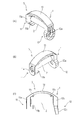
- A is a perspective view from one side of a pin member.
- B is a perspective view from the other side of a pin member.
- C is a front view of a pin member.
- A) is a figure shown about the structure of a control part.
- B) is a figure which shows a mode that a pin fixing tool rotates with a handle.
- A) is a figure shown about the structure of the pin fixing tool of a 2nd engaging part.
- B is sectional drawing explaining the shape of a rotation pin.
- C The figure shown about the structure of the pin fixing tool of a 2nd engaging part.
- (A) is a figure explaining the state which bent the connection part of the pin fixing tool.
- (B) is a figure explaining insertion of a rotation pin.
- (C) is a figure shown about the state which fitted the rotation pin in the 1st hole.
- (D) is a figure showing about the state where a rotation pin was inserted in the 2nd hole.
- FIG. 1 is a view showing a use state of a pin fixture 1 according to the present invention.
- a pin insertion portion 34 is provided in the main body 32 of the dispense head 3.
- the pin insertion portion 34 and the tip end portion 44 of the handle 4 are connected via the rotation pin 2.
- the pin fixture 1 In order to prevent unintentional disconnection of the rotating pin 2, the pin fixture 1 is used. At the time of maintenance, the handle 4 and the main body 32 can be disassembled by releasing the lock of the rotation pin 2 by the pin fixture 1 and extracting the rotation pin 2.
- FIGS. 2A, 2 ⁇ / b> B, and 2 ⁇ / b> C show the pin member 5 including the pin fixture 1 and the rotation pin 2.
- the pin fixture 1 includes a first engaging portion 11 and a second engaging portion 12 that are arranged apart from each other, a connecting portion 13 that connects the first engaging portion 11 and the second engaging portion 12, and And is configured as a single member as a whole.
- the pin fixture 1 can be composed of a synthetic resin molded product, and can be engaged and disengaged with respect to the rotating pin 2 as will be described later by being appropriately deformed and bent.
- Rotating pin 2 can be made of metal such as stainless steel, and similarly connects the main body of a metal dispensing head and the handle.
- the rotation pin 2 may be made of metal or synthetic resin.
- the first engaging portion 11 of the pin fixture 1 is provided with a pin fixing portion 11a for fixing one side portion of the rotating pin 2.
- the pin fixing portion 11a of the present embodiment is configured by a through hole, and the rotating pin 2 is firmly fixed to the pin fixing portion 11a by press-fitting and inserting one end of the rotating pin 2. It is like that.
- the pin fixing portion 11a is configured by a through-hole, it is possible to effectively prevent the rotating pin 2 from coming off in the radial direction. That is, for example, when the operator's finger is caught by the first engaging portion 11 and the portion of the first engaging portion 11 is pushed up, the pin fixing portion 11a is configured by a U-shaped notch. Then, there is a concern that the pivot pin 2 may fall off from the pin fixing portion 11a. However, such a fall off can be prevented by configuring the pin with a through hole.
- fixed part 11a will not be specifically limited if the structure which can fix a part of rotation pin 2 to the 1st engaging part 11 is used. That is, any configuration can be adopted as long as the first engagement portion 11 and the rotation pin 2 can be fixed (connected). Moreover, the rotation pin 2 may penetrate the 1st engaging part 11, and does not need to penetrate.
- the rotation pin 2 is made of synthetic resin, the rotation pin 2 and the pin fixture 1 are integrally formed, and the pin fixing portion 11a and the rotation pin 2 are connected. You can also.
- the first engaging portion 11 is provided with a restricting portion 11b for restricting an angle change caused by its own rotation with respect to the handle 4.
- the restricting portion 11b has the tip end portion 44 (arm portion) of the handle 4 in a state where the rotation pin 2 is inserted into the through hole 44a of the handle 4. ) Is a flat surface that contacts the flat lower surface.
- the control part 11b is provided also in the 2nd engagement part 12, or the control part 11b is provided in the 2nd engagement part 12 instead of the 1st engagement part 11, It is good as well.
- the restricting portion 11b has the distal end portion 44 (lower surface 44s) of the handle 4. ) Is restricted from being changed (rotation in the direction of arrow M (3 (A))).
- the second restricting portion 11c that comes into contact with the tip end portion 44 (upper surface 44u) of the handle 4 is provided above the restricting portion 11b.
- the angle change of the pin fixture 1 can be more reliably regulated by sandwiching the distal end portion 44 (arm portion) of the handle 4 by the both regulating portions 11b and 11c.
- a second restricting portion 12c is also provided on the second engaging portion 12 side, and the second engaging portion 12 side is also engaged with the handle. To be done.
- the pin fixture 1 can always be arranged at a specified angle (state shown in FIG. 1) in relation to the handle 4. If the angle change (rotation) of the pin fixture 1 is allowed, for example, the connecting portion 13 moves so as to fall forward of the front end portion 44 of the handle 4, and the finger is caught by the connecting portion 13, As a result, there is a concern that the pin fixing tool 1 may be pulled up and the rotating pin 2 may be pulled out, or the pin fixing tool 1 may be disengaged from the rotating pin 2. Such trouble can be prevented from occurring.
- the second engaging portion 12 is provided with a pin fixing portion 12a for fixing the rotating pin 2.
- the pin fixing portion 12a of the present embodiment is configured by a through hole, and one end of the rotating pin 2 is inserted into or extracted from the through hole.
- the pin fixing portion 12a is configured by a through-hole, it is possible to effectively prevent the rotating pin 2 from coming off in the radial direction. That is, for example, when the operator's finger is caught by the second engaging portion 12 and the portion of the second engaging portion 12 is pushed up, the second engaging portion 12 is configured with a U-shaped notch. Then, there is a concern that the pivot pin 2 will fall out of the second engaging portion 12. In this regard, such a drop-out can be prevented by forming the through hole.
- the configuration of the second engaging portion 12 is not particularly limited as long as a part of the rotation pin 2 can be fixed / unfixed with respect to the second engaging portion 12. That is, any configuration can be adopted as long as the second engaging portion 12 and the rotation pin 2 can be repeatedly fixed / unfixed. Further, the rotation pin 2 may or may not penetrate through the second engaging portion 12.
- the second engaging portion 12 is formed with a pin fixing portion 12a.
- the pin fixing portion 12a includes a first hole portion 14, a second hole portion 15, and a groove portion 16 that allows the first hole portion 14 and the second hole portion 15 to communicate with each other.
- the first hole portion 14 and the second hole portion 15 are arranged at positions displaced from each other in the radial direction of the rotation pin 2, and both are communicated by the groove portion 16.
- the rotating pin 2 of the present embodiment has an annular groove portion 2a in the circumferential direction formed at the end thereof.
- annular groove portion 2a When the annular groove portion 2a is fitted into the first hole portion 14, it is formed in the annular groove portion 2a.
- the vertical wall surface 2x hits the periphery of the first hole portion 14, and the movement of the rotating pin 2 in the axial direction is restricted. That is, the removal of the rotation pin 2 is restricted so that the vertical wall surface 2x is caught by the first hole portion 14.
- the width 16w of the groove 16 is slightly narrower than the width 2w of the annular groove 2a.
- the portion of the annular groove 2a that has entered the portion 15) can be moved to the second hole 15 (or the first hole 14) through the groove 16.
- the hole diameter R15 of the second hole portion 15 is configured to be smaller than the hole diameter R14 of the first hole portion 14, and an engagement wall portion 15x is formed around the second hole portion 15.
- FIG. 5C in the state where the annular groove 2a of the rotation pin 2 is positioned in the second hole 15, the vertical wall surface 2x of the rotation pin 2 is engaged with the engagement wall portion 15x, and the rotation is performed. The movement of the moving pin 2 in the axial direction is restricted. That is, the removal of the rotation pin 2 is restricted so that the vertical wall surface 2x abuts against the engagement wall portion 15x.
- the lower portion of the second engagement portion 12 is slightly inclined in the direction in which the lower portion opens (the direction opposite to the first engagement portion 11).
- the second engagement portion 12 can be easily picked with fingers.
- the surface of the second engagement portion 12 is provided with a plurality of anti-slip protrusions 12b, 12b that touch the belly of fingers. It is easy to hold.
- the rotation pin 2 when the rotation pin 2 is attached, first, as shown in FIG. 5A, the second engagement portion 12 is lifted to bend the connecting portion 13 and the rotation pin 2 is attached. The distal end portion 44 of the handle and the pin insertion portion 34 of the dispense head are inserted. Next, as shown in FIG. 5B, the second engagement portion 12 is pushed with the finger in the direction of the arrow R while aligning the first hole portion 14 with the position of the tip of the rotation pin 2. The rotation pin 2 is inserted into the one hole portion 14 to obtain the state shown in FIG. In the present embodiment, the tip portion 2b of the rotation pin 2 is tapered so that a configuration that can be easily inserted is realized.
- FIG. 5C shows a state in which the insertion into the first hole portion 14 is completed.
- the shoulder portion 12k of the second engagement portion 12 is pushed downward, so that FIG. As shown in D), the rotation pin 2 can be moved to the second hole 15.
- the rotating pin 2 is moved upward by pushing up the distal end portion 12s of the second engaging portion 12 in the state shown in FIG. It moves from the two holes 15 to the first hole 14 and returns to the position of FIG. Next, the tip 12s is picked with a finger and deformed so as to bend the second engaging portion 12 in the direction of the arrow L, whereby the annular groove 2a is extracted from the first hole 14 and the state shown in FIG. And
- the vertical wall surface 2x of the rotation pin 2 abuts against the engagement wall portion 15x, so that the rotation pin 2 is prevented from coming off.
- the width 16w of the groove 16 is configured to be slightly narrower than the width 2w of the annular groove 2a, so that the state shown in FIG. 5B cannot be obtained unless a force is intentionally applied. In this way, a first locking mechanism that prevents the rotation pin 2 from coming off is configured.
- the first and second lock mechanisms are configured, and the rotation pin 2 can be prevented from coming off in two stages. Even if a force is applied in the direction of the arrow L in the state of FIG. 5D, the second hole 15 has a small deformation amount (bending amount) at the second hole portion 15, so that the second hole It is extremely difficult to extract the rotating pin 2 from the portion 15. As a result, the function of the first locking mechanism becomes more reliable.
- the deformation amount (deflection amount) of the portion of the first hole portion 14 of the second engagement portion 12 is large.
- the rotation pin 2 can be extracted from the first hole portion 14 relatively easily.
- the rotation pin 2 can be removed, and a configuration with excellent operability can be realized.
- the connecting portion 13 is bent to engage / disengage the rotation pin 2 with respect to the second engaging portion 12.
- the rotating pin 2 can be pulled out from the dispensing head.
- the pin fixture 1 and the rotation pin 2 are not separated and remain connected on the first engagement portion 11 side, the number of components can be handled as one, and the pin fixture 1 It is possible to prevent the rotating pin 2 from being lost separately.
- the synthetic resin pin fixing tool 1 and the metal rotation pin 2 are separated and individually replaced or separated. Accordingly, each part can be reused or discarded as necessary, and a configuration excellent in cost reduction and environmental protection can be realized.
- the present invention can be implemented as described above. That is, as shown in FIG. 1 and FIG. A pin fixture 1 for removably fixing a rotating pin 2 of a handle 4 of a dispensing head 3 for attaching to a beverage container and taking out a beverage to the outside,
- the pin fixing tool has a restricting portion 11b for restricting a change in the angle of the handle 4 itself.
- a first engagement portion 11 disposed on one side in the longitudinal direction of the rotation pin 2;
- a second engagement portion 12 disposed on the other side in the longitudinal direction of the rotation pin 2,
- the restricting portion 11 b is provided in the first engaging portion 11 and / or the second engaging portion 12 and is configured to be restricted from rotating by engaging a part of the handle 4.
- the first engaging portion 11 is A through hole (pin fixing portion 11a) for inserting the rotation pin 2 is provided.
- the second engagement portion 12 is Suppose that it has a through-hole (pin fixing
- the through hole (pin fixing part 12a) of the second engaging part 12 is assumed to be detachably engaged with the rotating pin 2.
- the handle 4 can be separated by removing the pivot pin 2 from the second engagement portion 12 as necessary during maintenance or the like. Then, after the maintenance, the rotation pin 2 is engaged with the second engagement portion 12 again, so that it can be locked again, and the pin fixture 1 can be reused.
- the through hole of the second engagement portion 12 is A first hole portion 14 that moves in the axial direction of the rotation pin 2 to be engaged and disengaged with the rotation pin 2; A second hole 15 that is engaged with and disengaged from the rotation pin 2 at a position shifted from the first hole 14 in the radial direction; A groove 16 for moving the pivot pin 2 between the first hole and the second hole; It is supposed to have.
- connection part 13 which connects the 1st engaging part 11 and the 2nd engaging part 12.
- first engaging portion 11 and the second engaging portion 12 can be handled as one article, and a configuration with excellent handling properties can be realized.
- a pin member 5 having a pin fixture 1 and a rotation pin 2 is configured.
- the pin fixture 1 and the rotating pin 2 can be separated and individually replaced or separated. Each part can be reused or discarded as necessary, and a configuration excellent in cost reduction and environmental protection can be realized.
- the first engaging portion 11 and the second engaging portion 12 are connected by the connecting portion 13. May be configured as a separate member so that it can be disassembled. Moreover, it is good also as comprising only the 1st engaging part 11 and the 2nd engaging part 12 without providing the connection part 13. FIG. Moreover, it is good also as connecting the 1st engaging part 11 and the 2nd engaging part 12 with another members, such as a string, instead of providing the connection part 13. FIG. Further, in the through hole (pin fixing portion 12a) of the second engagement portion 12, in addition to the second hole portion 15, one or more through holes may be provided. In addition to the two-stage lock, a multi-stage lock mechanism such as a three-stage or even a four-stage can be realized.
Landscapes
- Devices For Dispensing Beverages (AREA)
- Snaps, Bayonet Connections, Set Pins, And Snap Rings (AREA)
Abstract
【課題】ディスペンスヘッドにおいてハンドルの回動ピンを固定するためのピン固定具について、新規な構成を提案する。 【解決手段】 飲料容器に取り付けて飲料を外部に取り出すためのディスペンスヘッド3のハンドル4の回動ピン2を、ハンドル4に対して着脱可能に固定するためのピン固定具1であって、ハンドル4に対する自身の角度変更を規制するための規制部11bを有する、ピン固定具1とする。ピン固定具1は、回動ピン2の長手方向一側に配置される第一係合部11と、回動ピン2の長手方向他側に配置される第二係合部12と、を有し、規制部11bは、第一係合部11、又は/及び、第二係合部12に設けられ、ハンドル4の一部に係合することで回動が規制される構成とする。
Description
本発明は、樽容器などの飲料容器に取り付けて飲料を外部に取り出すためのディスペンスヘッドに関するものであり、より詳しくは、ディスペンスヘッドに設けられるハンドルの回動ピンに関するものである。
従来、例えば、特許文献1に開示されるように、樽(タンク)容器などの飲料容器に取り付けて飲料を外部に取り出すためのディスペンスヘッドが知られている。
この種のディスペンスヘッドは、回動操作されるハンドルが設けられており、ハンドルを押し下げると炭酸ガス経路が飲料容器内に通じ、炭酸ガスによる飲料の押し出しがなされる構成としている。また、ディスペンスヘッドを取り外す際にハンドルが押し上げられると、炭酸ガス経路が閉鎖される構成としている。
このような押し下げ操作、押し上げ操作が行われるハンドルは、ディスペンスヘッド本体に対し回動ピンを介して枢結されており、ハンドルは回動ピンを軸に回動操作される。
また、ディスペンスヘッドは定期的にメンテナンスが必要とされるものであり、そのメンテナンスの際には、回動ピンを抜いてハンドルを本体から取り外して分解し、グリスを塗布するなどした後、再び回動ピンを用いてハンドルを本体に組み付けることが行われる。
上述したメンテナンスの際には、回動ピンの抜き差しが行われるが、メンテナンス性を考慮すると、回動ピンを抜き易い構成が好ましいといえる。
このようなメンテナンス性が求められる一方で、回動ピンが意図せずに抜けてしまうと予期せぬ不具合が生じる可能性がある。このため、回動ピンの抜けについては確実に防止することが求められるものである。即ち、回動ピンが抜けるとハンドルも本体から脱落してしまうことになり、仮に、炭酸ガス経路と繋がった状態でハンドルが脱落すると、高圧の炭酸ガスが勢い良く漏れるなどして、予期せぬ被害が生じる可能性があるのである。
本発明は、以上の課題に鑑み、ディスペンスヘッドにおいてハンドルの回動ピンを固定するためのピン固定具について、新規な構成を提案するものである。
本発明の解決しようとする課題は以上の如くであり、次にこの課題を解決するための手段を説明する。
即ち、請求項1に記載のごとく、
飲料容器に取り付けて飲料を外部に取り出すためのディスペンスヘッドのハンドルの回動ピンを、前記ハンドルに対して着脱可能に固定するためのピン固定具であって、
前記ハンドルに対する自身の角度変更を規制するための規制部を有する、ピン固定具とする。
飲料容器に取り付けて飲料を外部に取り出すためのディスペンスヘッドのハンドルの回動ピンを、前記ハンドルに対して着脱可能に固定するためのピン固定具であって、
前記ハンドルに対する自身の角度変更を規制するための規制部を有する、ピン固定具とする。
また、請求項2に記載のごとく、
前記回動ピンの長手方向一側に配置される第一係合部と、
前記回動ピンの長手方向他側に配置される第二係合部と、を有し、
前記規制部は、前記第一係合部、又は/及び、第二係合部に設けられ、前記ハンドルの一部に係合することで回動が規制される構成とする。
前記回動ピンの長手方向一側に配置される第一係合部と、
前記回動ピンの長手方向他側に配置される第二係合部と、を有し、
前記規制部は、前記第一係合部、又は/及び、第二係合部に設けられ、前記ハンドルの一部に係合することで回動が規制される構成とする。
また、請求項3に記載のごとく、
前記第一係合部は、
前記回動ピンを挿入するための貫通孔を有する。
前記第一係合部は、
前記回動ピンを挿入するための貫通孔を有する。
また、請求項4に記載のごとく、
前記第二係合部は、
前記回動ピンを挿入するための貫通孔を有する。
前記第二係合部は、
前記回動ピンを挿入するための貫通孔を有する。
また、請求項5に記載のごとく、
前記第二係合部の前記貫通孔は、前記回動ピンと係脱可能に嵌合される。
前記第二係合部の前記貫通孔は、前記回動ピンと係脱可能に嵌合される。
また、請求項6に記載のごとく、
前記第二係合部の前記貫通孔は、
前記回動ピンの軸方向に移動して前記回動ピンとの係脱がなされる第一孔部と、
前記第一孔部から半径方向にずれた位置において、前記回動ピンとの係脱がなされる第二孔部と、
前記第一孔部と前記第二孔部の間で前記回動ピンを移動させるための溝部と、
を有する。
前記第二係合部の前記貫通孔は、
前記回動ピンの軸方向に移動して前記回動ピンとの係脱がなされる第一孔部と、
前記第一孔部から半径方向にずれた位置において、前記回動ピンとの係脱がなされる第二孔部と、
前記第一孔部と前記第二孔部の間で前記回動ピンを移動させるための溝部と、
を有する。
また、請求項7に記載のごとく、
前記第一係合部と前記第二係合部を繋ぐ連結部を有する。
前記第一係合部と前記第二係合部を繋ぐ連結部を有する。
また、請求項8に記載のごとく、
請求項1乃至請求項7のいずれか一項に記載のピン固定具と、前記回動ピンと、を有するピン部材とする。
請求項1乃至請求項7のいずれか一項に記載のピン固定具と、前記回動ピンと、を有するピン部材とする。
本発明によれば、ピン固定具の角度変更(回転)によって生じる回動ピンの抜けなどといった不具合の発生を防止できる新規なピン固定具を実現することができる。
以下、添付図面を参照しながら本発明の容器停止装置をその例示的な実施形態を通して説明する。
図1は、本願発明に係るピン固定具1の使用状態について示す図である。ディスペンスヘッド3の本体32にピン挿通部34が設けられる。このピン挿通部34とハンドル4の先端部44が、回動ピン2を介して連結される。
図1は、本願発明に係るピン固定具1の使用状態について示す図である。ディスペンスヘッド3の本体32にピン挿通部34が設けられる。このピン挿通部34とハンドル4の先端部44が、回動ピン2を介して連結される。
そして、回動ピン2の意図せぬ抜けを防止するために、ピン固定具1が用いられる。メンテナンス時においては、ピン固定具1による回動ピン2のロックを解除して回動ピン2を抜き出すことで、ハンドル4と本体32を分解できるようになっている。
図2(A)(B)(C)は、ピン固定具1と回動ピン2から構成されるピン部材5について示すものである。
ピン固定具1は、互いに離間して配置される第一係合部11、及び、第二係合部12と、第一係合部11と第二係合部12を繋ぐ連結部13と、を有して構成され、全体として一つの部材として構成されている。
ピン固定具1は、互いに離間して配置される第一係合部11、及び、第二係合部12と、第一係合部11と第二係合部12を繋ぐ連結部13と、を有して構成され、全体として一つの部材として構成されている。
ピン固定具1は、合成樹脂成形品にて構成することができ、適度に変形、撓むことによって、後述するように、回動ピン2に対する係脱が可能に構成される。
回動ピン2は、ステンレスなどの金属により構成することができ、同じく金属製のディスペンスヘッドの本体と、ハンドルとを枢結させるものである。なお、回動ピン2は金属製とする他、合成樹脂製としてもよい。
ピン固定具1の第一係合部11には、回動ピン2の一側部分を固定するためのピン固定部11aが設けられる。本実施例のピン固定部11aは、貫通孔にて構成されており、回動ピン2の一端を圧入して挿入することで、回動ピン2がピン固定部11aに対し強固に固定されるようになっている。
また、ピン固定部11aが貫通孔にて構成されることで、回動ピン2が半径方向に抜けることを効果的に防ぐことができる。即ち、例えば、作業者の指が第一係合部11に引っかかり、第一係合部11の部分が押し上げられるような場合、仮に、U字条の切り欠きにてピン固定部11aが構成されると、回動ピン2がピン固定部11aから抜け落ちてしまうことが懸念されるが、貫通孔で構成することでこのような抜け落ちを防ぐことができる。
なお、ピン固定部11aの構成は、回動ピン2の一部を第一係合部11に固定できる構成であれば特に限定されるものではない。つまり、第一係合部11と回動ピン2の固定(連結)を維持できる構成であればいかなる構成も採用可能である。また、回動ピン2は第一係合部11を突き抜けてもよく、突き抜けなくてもよい。また、回動ピン2を合成樹脂にて構成する場合には、回動ピン2とピン固定具1を一体成形とし、ピン固定部11aと回動ピン2とが連結されてなる構成とすることもできる。
第一係合部11には、ハンドル4に対して自身の回動による角度変更を規制するための規制部11bが設けられる。本実施例では、図3(A)(B)に示すように、規制部11bは、回動ピン2がハンドル4の貫通孔44aに挿入された状態において、ハンドル4の先端部44(アーム部)の平坦な下面に当着する平坦面で構成される。なお、このような実施例で構成する他、規制部11bを第二係合部12にも設ける、或いは、規制部11bを第一係合部11の代わりに第二係合部12に設ける、こととしてもよい。
このような構成により、ピン固定具1に手が触れるなどして、ピン固定具1の角度変更(回転)が生じようとする際には、規制部11bがハンドル4の先端部44(下面44s)に当接しているため、その角度変更(矢印M方向の回転(3(A)))が規制される。
さらに、本実施例では、規制部11bの上方にハンドル4の先端部44(上面44u)に当接する第二規制部11cを設けることとしている。これにより、両規制部11b,11cにより、ハンドル4の先端部44(アーム部)を挟み込むようにして、ピン固定具1の角度変更をより確実に規制することができる。なお、本実施例では、図2(C)に示すように、第二係合部12側にも第二規制部12cが設けられ、第二係合部12側においてもハンドルとの係合が行われるようになっている。
以上の構成により、ハンドル4との関係において、ピン固定具1は常に規定の角度(図1の状態)で配置されることができる。仮に、ピン固定具1の角度変更(回転)が許容されてしまうと、例えば、連結部13がハンドル4の先端部44よりも前側に倒れるように移動して、連結部13に指が引っかかり、これにより、ピン固定具1を引っ張り上げて回動ピン2を引き抜いてしまうことや、ピン固定具1が回動ピン2から外れる等といった不具合の発生が懸念されるが、本実施例によればこのような不具合の発生を防止することができる。
図2(A)(B)に示すように、第二係合部12には、回動ピン2を固定するためのピン固定部12aが設けられる。本実施例のピン固定部12aは、貫通孔にて構成されており、回動ピン2の一端が貫通孔に対して挿入される、又は、貫通孔から抜き出されるようになっている。
また、ピン固定部12aが貫通孔にて構成されることで、回動ピン2が半径方向に抜けることを効果的に防ぐことができる。即ち、例えば、作業者の指が第二係合部12に引っかかり、第二係合部12の部分が押し上げられるような場合、仮に、U字条の切り欠きにて第二係合部12が構成されると、回動ピン2が第二係合部12から抜け落ちてしまうことが懸念される。この点に関し、貫通孔で構成することでこのような抜け落ちを防ぐことができる。
なお、第二係合部12の構成は、回動ピン2の一部を第二係合部12に対し固定/固定解除できる構成であれば特に限定されるものではない。つまり、第二係合部12と回動ピン2の固定/固定解除が繰り返し可能な構成であればいかなる構成も採用可能である。また、回動ピン2は第二係合部12を突き抜けてもよく、突き抜けなくてもよい。
本実施例では、図4(A)~(C)に示すように、第二係合部12にはピン固定部12aが形成される。このピン固定部12aは、第一孔部14と、第二孔部15と、第一孔部14と第二孔部15を連通させる溝部16と、を有する構成としている。第一孔部14と第二孔部15は、互いに回動ピン2の半径方向にずれた位置に配置され、溝部16により両者が連通されている。
本実施例の回動ピン2は、その端部に周方向の環状溝部2aが形設されており、この環状溝部2aが第一孔部14に嵌め込まれた際には、環状溝部2aに形成される縦壁面2xが第一孔部14の周辺に突き当たり、回動ピン2の軸方向の移動が規制される。つまり、縦壁面2xが第一孔部14に引っかかるようにして、回動ピン2の抜けが規制される。
図4(A)(B)に示すように、溝部16の幅16wは、環状溝部2aの幅2wよりも僅かに狭く構成され、力を加えることで、第一孔部14(又は第二孔部15)に進入した環状溝部2aの部位を、溝部16を通じて第二孔部15(又は第一孔部14)に移動させることができるようになっている。
図4(A)に示すように、第二孔部15の孔径R15は、第一孔部14の孔径R14よりも小さく構成され、第二孔部15の周囲に係合壁部15xが構成される。図5(C)に示すように、第二孔部15に回動ピン2の環状溝部2aが位置する状態では、回動ピン2の縦壁面2xが係合壁部15xに係合し、回動ピン2の軸方向の移動が規制される。つまり、縦壁面2xが係合壁部15xに突き当たるようにして、回動ピン2の抜けが規制される。
図2(C)及び図5(C)に示すように、第二係合部12の下部は、その下部が開く方向(第一係合部11と反対側方向)に僅かに傾斜しており、手指によって第二係合部12を摘み易い構成となっている。また、図4(C)に示すように、第二係合部12の表面には、手指の腹に触れる滑り止め用の突状部12b,12bが複数設けられており、摘んだ後にしっかりと保持しやすい構成となっている。
以上の構成において、回動ピン2を取り付ける際には、まず、図5(A)に示すように第二係合部12を持ち上げるようにして連結部13を撓ませるとともに、回動ピン2をハンドルの先端部44と、ディスペンスヘッドのピン挿通部34に挿通させる。次いで、図5(B)に示すように、回動ピン2の先端の位置に第一孔部14を合わせつつ、指で第二係合部12を矢印Rの方向に押すようにして、第一孔部14内に回動ピン2を挿入させて図5(C)の状態とする。なお、本実施例では、回動ピン2の先端部2bをテーパー形状とすることで挿入しやすい構成が実現される。
図5(C)は、第一孔部14への挿入が完了した様子を示すものであり、この状態において、第二係合部12の肩部12kを下方向に押し下げることにより、図5(D)に示すように第二孔部15へと回動ピン2を移動させることができる。
逆に、回動ピン2を第二係合部12から外す際には、図5(D)に示す状態において第二係合部12の先端部12sを押し上げることで、回動ピン2を第二孔部15から第一孔部14へ移動させて図5(C)の位置に戻す。次いで、先端部12sを指で摘んで矢印Lの方向に第二係合部12を撓ませるように変形させることで、環状溝部2aを第一孔部14から抜き出して図5(B)の状態とする。
以上の構成において、図5(D)の状態となった後は、回動ピン2の縦壁面2xが係合壁部15xに突き当たるため、回動ピン2の抜けが規制される。また、溝部16の幅16wは、環状溝部2aの幅2wよりも僅かに狭く構成されることで、意図的に力を加えない限りは、図5(B)の状態とすることができない。このようにして、回動ピン2の抜けを防止する第一のロック機構が構成される。
さらに、図5(C)の状態においても、意図的に力を加えない限りは、縦壁面2xが第一孔部14に引っかかるため、図5(B)の状態とすることができない。このようにして、回動ピン2の抜けを防止する第二のロック機構が構成される。
以上のようにして第一、第二のロック機構が構成され、回動ピン2の抜けを二段階で防止することができる。なお、図5(D)の状態において矢印Lの方向に力を加えたとしても、第二係合部12の第二孔部15の箇所の変形量(撓み量)が小さいため、第二孔部15から回動ピン2を抜き出すことが極めて困難である。このことにより、第一のロック機構の機能がより確実なものとなる。
他方、図5(C)の状態において矢印Lの方向に力を加えた場合には、第二係合部12の第一孔部14の箇所の部位の変形量(撓み量)が大きいため、第一孔部14から回動ピン2を比較的容易に抜き出すことができる。このように意図的に図5(C)の状態にした上で力を加えることによれば、回動ピン2を外すことができ、操作性に優れた構成が実現できる。
また、以上の一連の操作においては、図5(A)に示すように、連結部13を撓ませることで、第二係合部12に対する回動ピン2の係合/係合解除を行いつつ、ディスペンスヘッドから回動ピン2を引き抜くことができる。そして、この場合、ピン固定具1と回動ピン2は分離せずに第一係合部11側で接続されたままであるため、部品数を一つとして扱うことができ、ピン固定具1と回動ピン2が別々になって紛失することを防止できる。
また、回動ピン2のみであると転がり易く、紛失しやすいことや、置き場に困るということもあるが、ピン固定具1とともに一体に構成されることで転がり難くなり、取扱が容易になる。
他方、所定の使用期間の経過後や、破損した場合などにおいては、合成樹脂製のピン固定具1と、金属製の回動ピン2を分離して個別に交換、或いは、分別処理などをすることができ、これにより、必要に応じて各部剤を再利用や廃棄することが可能となり、コスト削減や環境保護に優れた構成を実現することができる。
以上のように本発明を実施することができる。
即ち、図1、及び、図2(A)に示すように、
飲料容器に取り付けて飲料を外部に取り出すためのディスペンスヘッド3のハンドル4の回動ピン2を、ハンドル4に対して着脱可能に固定するためのピン固定具1であって、
ハンドル4に対する自身の角度変更を規制するための規制部11bを有する、ピン固定具とするものである。
即ち、図1、及び、図2(A)に示すように、
飲料容器に取り付けて飲料を外部に取り出すためのディスペンスヘッド3のハンドル4の回動ピン2を、ハンドル4に対して着脱可能に固定するためのピン固定具1であって、
ハンドル4に対する自身の角度変更を規制するための規制部11bを有する、ピン固定具とするものである。
これにより、ピン固定具1の角度変更(回転)によって生じる不具合の発生を防止できる。
また、図2(A)~(C)に示すように、
回動ピン2の長手方向一側に配置される第一係合部11と、
回動ピン2の長手方向他側に配置される第二係合部12と、を有し、
規制部11bは、第一係合部11、又は/及び、第二係合部12に設けられ、ハンドル4の一部に係合することで回動が規制される構成とする。
回動ピン2の長手方向一側に配置される第一係合部11と、
回動ピン2の長手方向他側に配置される第二係合部12と、を有し、
規制部11bは、第一係合部11、又は/及び、第二係合部12に設けられ、ハンドル4の一部に係合することで回動が規制される構成とする。
これにより、ピン固定具の角度変更(回転)を規制する構成を実現できる。
また、図2(A)(B)に示すように、
第一係合部11は、
回動ピン2を挿入するための貫通孔(ピン固定部11a)を有する、こととする。
第一係合部11は、
回動ピン2を挿入するための貫通孔(ピン固定部11a)を有する、こととする。
これにより、第一係合部11において、回動ピン2が半径方向に抜けることを防止できる。
また、図2(A)(B)に示すように、
第二係合部12は、
回動ピン2を挿入するための貫通孔(ピン固定部12a)を有する、こととする。
第二係合部12は、
回動ピン2を挿入するための貫通孔(ピン固定部12a)を有する、こととする。
これにより、第二係合部12において、回動ピン2が半径方向に抜けることを防止できる。
また、図5(A)~(D)に示すように、
第二係合部12の貫通孔(ピン固定部12a)は、回動ピン2と係脱可能に嵌合される、こととする。
第二係合部12の貫通孔(ピン固定部12a)は、回動ピン2と係脱可能に嵌合される、こととする。
これにより、メンテナンス時など必要に応じて第二係合部12から回動ピン2を外すことで、回動ピン2を抜き出してハンドル4を分離することができる。そして、メンテナンス後は再び第二係合部12に回動ピン2を係合するで、再びロックすることができ、ピン固定具1を再利用することができる。
また、図4(A)~(C)に示すように、
第二係合部12の貫通孔は、
回動ピン2の軸方向に移動して回動ピン2との係脱がなされる第一孔部14と、
第一孔部14から半径方向にずれた位置において、回動ピン2との係脱がなされる第二孔部15と、
第一孔部と第二孔部の間で回動ピン2を移動させるための溝部16と、
を有する、こととする。
第二係合部12の貫通孔は、
回動ピン2の軸方向に移動して回動ピン2との係脱がなされる第一孔部14と、
第一孔部14から半径方向にずれた位置において、回動ピン2との係脱がなされる第二孔部15と、
第一孔部と第二孔部の間で回動ピン2を移動させるための溝部16と、
を有する、こととする。
これにより、回動ピン2の意図せぬ抜けを防止するための二段階のロック機構を実現することができる。
また、図2(A)に示すように、
第一係合部11と第二係合部12を繋ぐ連結部13を有する、こととする。
第一係合部11と第二係合部12を繋ぐ連結部13を有する、こととする。
これにより、第一係合部11と第二係合部12を一物品として取り扱うことができ、取扱性に優れた構成を実現できる。
また、図2(A)に示すように、
ピン固定具1と、回動ピン2と、を有するピン部材5として構成することとする。
ピン固定具1と、回動ピン2と、を有するピン部材5として構成することとする。
これにより、例えば、回動ピン2のみであると転がり易く、紛失しやすいことや、置き場に困るということもあるが、ピン固定具1とともにピン部材5として一体に構成されることで転がり難くなり、取扱が容易になる。また、所定の使用期間の経過後や、破損した場合などにおいては、ピン固定具1と、回動ピン2を分離して個別に交換、或いは、分別処理などをすることができ、これにより、必要に応じて各部剤を再利用や廃棄することが可能となり、コスト削減や環境保護に優れた構成を実現することができる。
また、以上の説明においては、図2(A)~(C)に示すように、連結部13により第一係合部11と第二係合部12が連結される構成としたが、各部位を別部材で構成し、分解可能に構成してもよい。また、連結部13を設けずに、第一係合部11と第二係合部12のみで構成することとしてもよい。また、連結部13を設ける代わりに第一係合部11と第二係合部12を紐などの別の部材で繋ぐこととしてもよい。また、第二係合部12の貫通孔(ピン固定部12a)において、第二孔部15に加え、さらにもう一つ、或いは、複数の貫通孔を設けることとしてもよい、これによれば、二段階のロックに加え、三段階、さらには、四段階などの多段ロック機構を実現することもできる。
1 ピン固定具
2 回動ピン
3 ディスペンスヘッド
4 ハンドル
5 ピン部材
11 第一係合部
11a ピン固定部
11b 規制部
11c 第二規制部
12 第二係合部
12a ピン固定部
12c 第二規制部
13 連結部
14 第一孔部
15 第二孔部
16 溝部
2 回動ピン
3 ディスペンスヘッド
4 ハンドル
5 ピン部材
11 第一係合部
11a ピン固定部
11b 規制部
11c 第二規制部
12 第二係合部
12a ピン固定部
12c 第二規制部
13 連結部
14 第一孔部
15 第二孔部
16 溝部
Claims (8)
- 飲料容器に取り付けて飲料を外部に取り出すためのディスペンスヘッドのハンドルの回動ピンを、前記ハンドルに対して着脱可能に固定するためのピン固定具であって、
前記ハンドルに対する自身の角度変更を規制するための規制部を有する、
ピン固定具。 - 前記回動ピンの長手方向一側に配置される第一係合部と、
前記回動ピンの長手方向他側に配置される第二係合部と、を有し、
前記規制部は、前記第一係合部、又は/及び、第二係合部に設けられ、前記ハンドルの一部に係合することで回動が規制される構成とする、
ことを特徴とする請求項1に記載のピン固定具。 - 前記第一係合部は、
前記回動ピンを挿入するための貫通孔を有する、
ことを特徴とする請求項2に記載のピン固定具。 - 前記第二係合部は、
前記回動ピンを挿入するための貫通孔を有する、
ことを特徴とする請求項3に記載のピン固定具。 - 前記第二係合部の前記貫通孔は、前記回動ピンと係脱可能に嵌合される、
ことを特徴とする請求項4に記載のピン固定具。 - 前記第二係合部の前記貫通孔は、
前記回動ピンの軸方向に移動して前記回動ピンとの係脱がなされる第一孔部と、
前記第一孔部から半径方向にずれた位置において、前記回動ピンとの係脱がなされる第二孔部と、
前記第一孔部と前記第二孔部の間で前記回動ピンを移動させるための溝部と、
を有する、
ことを特徴とする請求項5に記載のピン固定具。 - 前記第一係合部と前記第二係合部を繋ぐ連結部を有する、
ことを特徴とする請求項1乃至請求項6のいずれか一項に記載のピン固定具。 - 請求項1乃至請求項7のいずれか一項に記載のピン固定具と、
前記回動ピンと、
を有するピン部材。
Applications Claiming Priority (2)
| Application Number | Priority Date | Filing Date | Title |
|---|---|---|---|
| JP2017035644A JP6879503B2 (ja) | 2017-02-28 | 2017-02-28 | ディスペンスヘッド用のピン固定具、及び、それを有するピン部材 |
| JP2017-035644 | 2017-02-28 |
Publications (1)
| Publication Number | Publication Date |
|---|---|
| WO2018159216A1 true WO2018159216A1 (ja) | 2018-09-07 |
Family
ID=63370956
Family Applications (1)
| Application Number | Title | Priority Date | Filing Date |
|---|---|---|---|
| PCT/JP2018/003683 Ceased WO2018159216A1 (ja) | 2017-02-28 | 2018-02-02 | ディスペンスヘッド用のピン固定具、及び、それを有するピン部材 |
Country Status (2)
| Country | Link |
|---|---|
| JP (1) | JP6879503B2 (ja) |
| WO (1) | WO2018159216A1 (ja) |
Citations (2)
| Publication number | Priority date | Publication date | Assignee | Title |
|---|---|---|---|---|
| US4291821A (en) * | 1979-10-04 | 1981-09-29 | The Perlick Company, Inc. | Keg tapping system unit and valve interlock |
| US4538746A (en) * | 1983-06-29 | 1985-09-03 | Vending Components, Inc. | Keg-tapping assembly |
-
2017
- 2017-02-28 JP JP2017035644A patent/JP6879503B2/ja active Active
-
2018
- 2018-02-02 WO PCT/JP2018/003683 patent/WO2018159216A1/ja not_active Ceased
Patent Citations (2)
| Publication number | Priority date | Publication date | Assignee | Title |
|---|---|---|---|---|
| US4291821A (en) * | 1979-10-04 | 1981-09-29 | The Perlick Company, Inc. | Keg tapping system unit and valve interlock |
| US4538746A (en) * | 1983-06-29 | 1985-09-03 | Vending Components, Inc. | Keg-tapping assembly |
Also Published As
| Publication number | Publication date |
|---|---|
| JP2018140796A (ja) | 2018-09-13 |
| JP6879503B2 (ja) | 2021-06-02 |
Similar Documents
| Publication | Publication Date | Title |
|---|---|---|
| US2816471A (en) | Clevis pin with lockable operating means | |
| JP7179946B2 (ja) | 眼内レンズ挿入器 | |
| US8869354B2 (en) | Ratchet buckle for helmets | |
| JP3171841U (ja) | 塗装用ローラハンドルの長柄連結具 | |
| US8292266B2 (en) | Hammer with leverage No. II | |
| CN108595034B (zh) | 笔体弹出结构、触控笔以及电子设备 | |
| WO2011090983A1 (en) | Ring pliers | |
| KR20180133387A (ko) | 수동 이기 잠금 기구 | |
| EP1840039A1 (en) | Tubular case | |
| JP6240033B2 (ja) | 抜け止め付コネクタ | |
| WO2018159216A1 (ja) | ディスペンスヘッド用のピン固定具、及び、それを有するピン部材 | |
| US6761705B1 (en) | Safety syringe device with a needle bending device | |
| US9616216B2 (en) | Releasable blocking system of a catheter | |
| JP6577534B2 (ja) | 穿刺針カートリッジ | |
| JP5819781B2 (ja) | 定量シリンジ型噴出器 | |
| WO2017072992A1 (ja) | シリンジ型噴出器 | |
| CN107110336B (zh) | 能够控制变速箱操纵杆的位置的装置 | |
| JP5865315B2 (ja) | 噴霧器 | |
| CN106246677B (zh) | 锁定装置及具有其的吹吸机 | |
| JP5677833B2 (ja) | シリンジ容器 | |
| JP2014068886A (ja) | 定量シリンジ型噴出器 | |
| JP5468875B2 (ja) | エアゾール噴射装置 | |
| CN205620900U (zh) | 服务器机架 | |
| JP5464362B2 (ja) | プラグユニット | |
| CN110624158A (zh) | 注入器 |
Legal Events
| Date | Code | Title | Description |
|---|---|---|---|
| 121 | Ep: the epo has been informed by wipo that ep was designated in this application |
Ref document number: 18761421 Country of ref document: EP Kind code of ref document: A1 |
|
| NENP | Non-entry into the national phase |
Ref country code: DE |
|
| 122 | Ep: pct application non-entry in european phase |
Ref document number: 18761421 Country of ref document: EP Kind code of ref document: A1 |