WO2018159196A1 - 表示装置及びテレビジョン受信機 - Google Patents
表示装置及びテレビジョン受信機 Download PDFInfo
- Publication number
- WO2018159196A1 WO2018159196A1 PCT/JP2018/003038 JP2018003038W WO2018159196A1 WO 2018159196 A1 WO2018159196 A1 WO 2018159196A1 JP 2018003038 W JP2018003038 W JP 2018003038W WO 2018159196 A1 WO2018159196 A1 WO 2018159196A1
- Authority
- WO
- WIPO (PCT)
- Prior art keywords
- covering member
- display device
- hole
- display
- display unit
- Prior art date
- Legal status (The legal status is an assumption and is not a legal conclusion. Google has not performed a legal analysis and makes no representation as to the accuracy of the status listed.)
- Ceased
Links
Images




Classifications
-
- G—PHYSICS
- G09—EDUCATION; CRYPTOGRAPHY; DISPLAY; ADVERTISING; SEALS
- G09F—DISPLAYING; ADVERTISING; SIGNS; LABELS OR NAME-PLATES; SEALS
- G09F9/00—Indicating arrangements for variable information in which the information is built-up on a support by selection or combination of individual elements
-
- H—ELECTRICITY
- H04—ELECTRIC COMMUNICATION TECHNIQUE
- H04N—PICTORIAL COMMUNICATION, e.g. TELEVISION
- H04N5/00—Details of television systems
- H04N5/64—Constructional details of receivers, e.g. cabinets or dust covers
-
- H—ELECTRICITY
- H04—ELECTRIC COMMUNICATION TECHNIQUE
- H04N—PICTORIAL COMMUNICATION, e.g. TELEVISION
- H04N5/00—Details of television systems
- H04N5/64—Constructional details of receivers, e.g. cabinets or dust covers
- H04N5/645—Mounting of picture tube on chassis or in housing
Definitions
- the present disclosure relates to a display device and a television receiver.
- Display devices including a display unit that displays an image on the front are used in devices such as television receivers and personal computers.
- the display unit includes, for example, a liquid crystal panel and a backlight device that irradiates the liquid crystal panel with light from the back.
- the display device further includes a covering member (front cabinet) disposed so as to cover the front peripheral edge and the side surface, a fixing member (intermediate chassis) disposed on the rear surface of the display unit and to which the covering member is fixed. (For example, refer to Patent Document 1).
- the display device is assembled by attaching a covering member and a fixing member to the display portion after the display portion is assembled.
- the display unit is assembled, for example, by placing the liquid crystal panel on a work table with the display surface facing downward and attaching a backlight device from above.
- the covering member After assembling the display unit, attach the covering member to the display unit.
- the covering member is attached by covering and fixing the covering member from the front side of the display unit. In this case, the attachment is performed through a process of rotating the display unit 180 degrees so that the display surface faces upward.
- the covering member is placed at a predetermined position with respect to the display portion from the side of the display portion with the display surface facing the work table. In some cases, the covering member is fixed by holding the cover.
- the covering member when the covering member is fixed from the side surface of the display unit, it is not easy to hold the covering member at a predetermined position with respect to the display unit so that it does not drop or shift, and the covering member can be attached. There is a problem that it is not easy.
- the present disclosure has been made in view of such circumstances, and an object thereof is to provide a display device and a television receiver in which a covering member can be easily attached to a display unit.
- a display device includes a display unit that displays an image on a front surface, a first surface that covers a front side of a peripheral portion of the display unit, and a back surface of the display unit from the first surface.
- a covering member having a projecting second surface; a fixing member located on the back side of the display unit; and the fixing member to which the covering member is fixed; an engaging body protruding from the second surface; and the fixing member.
- An engagement hole that engages with the engagement body is provided.
- the covering member and the fixing member extend along the peripheral edge portion, and protrusions are provided at both end portions of the second surface, and the fixing member is inserted into which the protrusion is inserted. A hole is provided.
- a plurality of the engaging bodies and engaging holes are provided along the peripheral edge.
- the one engaging body and the one engaging hole engaged with the one engaging body regulate relative movement of the covering member and the fixing member in the direction along the peripheral edge portion.
- the engaging body is provided with a claw portion protruding from the first surface side.
- the covering member and the engaging body sandwich the display unit.
- the covering member and the fixing member are fixed by screwing.
- the screwing position is adjacent to the engagement hole.
- a television receiver includes the display device described above and a reception unit that receives a television broadcast, and the display unit includes the display unit based on the television broadcast received by the reception unit. It is characterized by displaying video.
- the covering member can be easily attached to the display unit.
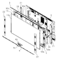
- FIG. 1 is a perspective view of a display device according to an embodiment. It is a disassembled perspective view of a display apparatus.
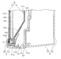
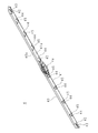
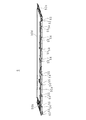
- FIG. 3 is a sectional view taken along line III-III in FIG. It is a perspective view of a covering member. It is the elements on larger scale of a covering member. It is a perspective view of a middle cabinet. It is the elements on larger scale of a middle cabinet. It is the elements on larger scale of a middle cabinet. It is the elements on larger scale of a middle cabinet. It is explanatory drawing of the assembly
- FIG. 1 is a perspective view of a display device according to an embodiment.
- FIG. 2 is an exploded perspective view of the display device.
- reference numeral 1 denotes a display device.
- the display device 1 includes a display unit 10 having a rectangular display surface 10a.
- the display device 1 includes a tuner 11 that receives broadcast waves from an antenna and a decoder 12 that decodes encoded broadcast waves.
- the display device 1 is configured as a television receiver.
- the display device 1 includes two speaker units 2 and 2 disposed so as to sandwich the display surface 10a in the longitudinal direction of the display surface 10a, a top plate 3 disposed on one long side of the display surface 10a, On the other long side, a covering member 4 that covers the peripheral edge of the display surface 10a is provided.
- the display device 1 is used so that the display surface 10a faces the front side, the top plate 3 is on the upper side, the covering member 4 is on the lower side, and the two speaker units 2 and 2 are positioned on the left and right.
- the up / down, front / rear, and left / right directions in the usage state of the display device 1 are used.
- FIG. 3 is a cross-sectional view taken along line III-III in FIG.
- the display unit 10 has a known configuration, and includes a liquid crystal panel 13 whose front surface forms a display surface 10 a and a backlight device 14 that irradiates light on the rear surface of the liquid crystal panel 13.
- the backlight device 14 includes a chassis 140 that has a rectangular bottom plate and a side plate that rises from each of the four sides of the bottom plate, and has a box shape in which the entire surface facing the bottom plate is open.
- a plurality of LEDs 141 are arranged in parallel on the bottom plate of the chassis 140, and these LEDs 141 are exposed to the front side from the reflection sheet 142 covering the entire inner surface of the chassis 140.
- the liquid crystal panel 13 is supported on the opening side of the chassis 140 via the panel chassis 144.
- the rear surface of the liquid crystal panel 13 faces the bottom plate of the chassis 140.
- a rectangular diffusion plate 145 and an optical sheet 146 are disposed between the liquid crystal panel 13 and the chassis 140.
- the panel chassis 144 sandwiches the diffusion plate 145 between the opening edge of the chassis 140 and supports the optical sheet 146 in the vicinity of the rear surface of the liquid crystal panel 13.
- the peripheral part of the display surface 10 a of the liquid crystal panel 13 is covered with the bezel 15.
- the bezel 15 rises perpendicularly from the outer peripheral edge of the rectangular frame-shaped front plate that sandwiches the peripheral portion of the liquid crystal panel 13 with the panel chassis 144, and is fixed to the chassis 140 and the panel chassis 144. And side plates.
- Each speaker unit 2 has a rectangular box shape, and its long side is arranged along the short side of the display surface 10a. As shown in FIG. 2, each speaker unit 2 includes a speaker body 20, a box 21, and a cover 22 that are stacked in the front-rear direction.
- the box 21 has an opening on the front side and is arranged at one end in the longitudinal direction of the display unit 10.
- the speaker body 20 is accommodated in the box 21.
- the box 21 forms a room in which the speaker main body 20 is accommodated by a first short side portion or a second short side portion of the middle cabinet 5 described later disposed on the opening side.
- a cover 22 is covered from the front side of the first short side portion or the second short side portion.
- the top plate 3 is long in the left-right direction and covers the upper side surface of the display unit 10 and the upper side surfaces of the speaker units 2 and 2.
- the top plate 3 improves the aesthetic appearance of the display device 1 from above.
- FIG. 4 is a rear perspective view of the covering member 4.
- the covering member 4 is a member having an L-shaped cross section including a front plate 40 and a lower plate 41 that rises from one long side of the one surface 40a of the front plate 40. Both end portions of the front plate 40 are thicker than the other portions, and the thick portions are bent obliquely rearward. Further, the center portion of the front plate 40 is curved so as to protrude to the opposite side of the lower plate 41.
- the lower plate 41 is curved at the center so as to be recessed on the opposite side of the front plate 40.
- a curved portion 4 a is formed at the center of the covering member 4 due to the curvature of the central portions of the front plate 40 and the lower plate 41.
- FIG. 5 is a partially enlarged view of the covering member 4.
- FIG. 5 shows one end of the covering member 4 in the longitudinal direction.
- On one surface 41a of the lower plate 41 a single pin 42 projects from one end in the longitudinal direction.
- the pin 42 protrudes from the one surface 41a in the same direction as the front plate 40 and has a cross-shaped cross section.
- the tip portion of the pin 42 is narrowed toward the tip.
- a single first through hole 43 penetrating in the thickness direction is provided adjacent to the pin 42 at one end of the lower plate 41 in the longitudinal direction.
- the first through hole 43 is located on one end side in the longitudinal direction from the pin 42.
- a pin 42 and a first through hole 43 are provided at the other longitudinal end of the lower plate 41.
- a plurality of engaging bodies 44 projecting from one surface 41a and a plurality of second through holes 45 penetrating in the thickness direction (eight in FIG. 4 each). Is provided.
- Each engaging body 44 and each second through hole 45 are adjacent to each other to form a pair, and four pairs are provided with the curved portion 4a interposed therebetween. Each pair is separated by a predetermined distance.
- the engaging body 44 is positioned on the end side in the longitudinal direction from the second through hole 45, and the arrangement order in each pair is reversed on both sides of the curved portion 4a. It has become.
- Each engagement body 44 is substantially the same size, protrudes from the one surface 41a in the same direction as the front plate 40, and has a long rectangular cross section along the one surface 41a.
- a claw portion 440 that protrudes toward the one surface 40 a side of the front plate 40 is provided at the distal end portion of the engaging body 44.
- the second through hole 45 penetrates in the thickness direction of the lower plate 41.
- the lower plate 41 is formed with a so-called draft and has an obtuse angle with respect to the front plate 40.
- the peripheral edge of the first through hole 43 and the peripheral edge of the second through hole 45 form a flat seat, and are formed by so-called forced punching. Due to the draft, a gap is formed between the covering member 4 and the middle cabinet 5 after assembling the display device 1 to be described later, and the warpage of each member can be absorbed.
- the covering member 4 is attached to the lower side of the display unit 10, the one surface 40 a of the front plate 40 covers the peripheral edge of the display surface 10 a, and the one surface 41 a of the lower plate 41 projects to the back side of the display unit 10 to display The lower end surface of the portion 10 is covered.
- the curved portion 4 a forms a space with the bezel 15.
- the light-emitting portion 4b is accommodated in the space (see FIG. 2).
- the light emitting unit 4b emits light upward using the LED as a light source.
- the display device 1 further includes a middle cabinet 5 arranged on the rear side of the display unit 10 as shown in FIG.
- the middle cabinet 5 has a first long side portion 50a and a second long side portion 50d that are parallel to each other, and a first short side portion 50b and a second short side portion 50c that connect both ends thereof, and has a rectangular frame shape. Make.
- the middle cabinet 5 is arranged on the rear side of the display unit 10 with the second long side portion 50d as the upper side and the first long side portion 50a as the lower side.
- the display device 1 includes a rear cabinet 6 disposed on the rear side of the middle cabinet 5.
- the rear cabinet 6 has a rectangular plate shape having a rectangular plate-like bottom plate 6a and side plates 6b rising from each of the four sides of the bottom plate 6a.
- the rear cabinet 6 is arranged with the opening facing forward, and the bottom plate 6 a faces the chassis 140 of the backlight device 14.
- FIG. 6 is a perspective view of the middle cabinet 5. 7 and 8 are partially enlarged views of the middle cabinet 5.
- FIG. FIG. 7 shows the longitudinal direction one end part side of the middle cabinet 5
- FIG. 8 shows the longitudinal direction center part.
- An insertion hole 52 and a first screw hole 53 are juxtaposed in the longitudinal direction on one end side of the first long side portion 50a.
- the end shape of the first long side portion 50 a corresponds to the end shape of the covering member 4 shown in FIG. 5, and the positions of the insertion hole 52 and the first screw hole 53 are provided at the end portion of the covering member 4.
- the pin 42 and the first through hole 43 are made to correspond to each other.
- the insertion hole 52 is a long hole that penetrates the first long side portion 50a in the thickness direction and extends in the longitudinal direction of the first long side portion 50a.
- the width of the insertion hole 52 is a dimension in which there is almost no gap when the pin 42 is inserted.
- the first screw hole 53 is located on the end side in the longitudinal direction from the insertion hole 52.
- the first screw hole 53 is aligned with the first through hole 43 when the pin 42 is fitted into the insertion hole 52.
- the insertion hole 52 and the first screw hole 53 are provided at the other end of the first long side portion 50a (see FIG. 6).
- a plurality of rectangular engagement holes 54 and second screw holes 55 are arranged in parallel in the longitudinal direction on the first long side portion 50a.
- the positions of the engagement holes 54 and the second screw holes 55 correspond to the positions of the engagement bodies 44 and the second through holes 45 provided in the covering member 4, and the respective engagement holes 54 and the respective second screw holes 55 are Pairs are adjacent to each other.
- the engagement holes 54 are located on the end side in the longitudinal direction from the second screw holes 55. Therefore, the arrangement order of the pair of the engagement hole 54 and each second screw hole 55 is reversed on both sides of the bending portion 4a.
- the engagement hole 54 is a long hole that penetrates the first long side portion 50a in the thickness direction and extends in the longitudinal direction of the first long side portion 50a, and has a width and a length that allow the engagement body 44 to be inserted. is doing.
- the second screw hole 55 is aligned with the second through hole 45 when the engaging body 44 is inserted into the engaging hole 54.
- the length L ⁇ b> 1 of the engagement hole 54 located at the center of the plurality of engagement holes 54 is smaller than the length L ⁇ b> 2 of the remaining engagement holes 54.
- the width L ⁇ b> 1 of the engagement hole 54 is a dimension that fits with almost no gap in the longitudinal direction when the engagement body 44 is inserted.
- the width L2 is a dimension with a margin for error absorption with respect to the engaging body 44 to be inserted.
- the covering member 4 is arranged with the front plate 40 along the front surface of the display unit 10 and the rear portion of the lower plate 41 overlapped with the lower edge of the first long side portion 50 a of the middle cabinet 5.
- the pins 42 protruding from both ends of the lower plate 41 are inserted into the insertion holes 52 provided at both ends of the first long side portion 50 a.
- coated member 4 can be positioned easily.
- the covering member 4 is temporarily fixed in the front-rear direction.
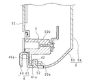
- Each engaging body 44 is elastically restored after being inserted into the engaging hole 54, and the front surface engages with the engaging hole 54 by the claw portion 440 as shown in FIG. Temporarily fixed without any positional misalignment.
- the covering member 4 holds the display unit 10 between the front plate 40 and the engagement body 44. Therefore, the clearance gap between the coating
- the engaging body 44 is inserted into the engaging hole 54 having the length L1
- the relative movement of the covering member 4 and the middle cabinet 5 in the longitudinal direction of the first long side portion 50a is restricted.
- No. 4 can prevent displacement in the left-right direction and can easily perform positioning.
- the first through holes 43 provided at both ends of the lower plate 41 of the covering member 4 are aligned with the first screw holes 53 adjacent to the insertion hole 52 provided in the first long side portion 50a, It fixes with the screw 70 as shown in FIG.
- the second through holes 45 provided in the lower plate 41 of the covering member 4 are aligned with the second screw holes 55 provided in the first long side portion 50a and adjacent to the engagement holes 54, as shown in FIG. As shown, it is fixed by screws 71.
- the covering member 4 and the middle cabinet 5 are fixed by screwing.
- the 1st through-hole 43 and the 2nd through-hole 45 are so-called fool holes, and it is set as the dimension which gave the allowance for alignment.
- the engaging body 44 and the second through hole 45 are adjacent to each other, and the engaging hole 54 and the second screw hole 55 are adjacent to each other. Therefore, the screwing position is adjacent to the engaging body 44 and the engaging hole 54. Thereby, by inserting each engaging body 44 into each engaging hole 54, the influence by the bending etc. of the coating
- Flat seats are provided at the peripheral edge portions of the first through hole 43 and the second through hole 45 and are in close contact with the first long side portion 50a after being screwed, so that the covering member 4 and the middle cabinet 5 are positioned. It can be firmly fixed without displacement. Thereby, the clearance gap between the coating
- the display unit 10 is placed on a flat work table (not shown) with the display surface 10a facing downward so that the long side portion to which the covering member 4 is attached protrudes from the work table. 5 is attached. After the middle cabinet 5 is attached, the cover plate is assembled as described above.
- each engaging body 44 is inserted into the engaging hole 54 and engaged, and even if the operator releases the hand from the covering member 4, the covering member 4 is temporarily fixed to the display unit 10 because it does not fall. .
- the operation is controlled by a control unit (not shown).
- a user of the display device 1 can transmit an instruction to the control unit by operating an operation unit such as a remote controller (hereinafter referred to as “remote controller”) that communicates with the display device 1 using infrared rays.
- remote controller a remote controller that communicates with the display device 1 using infrared rays.
- the control unit By the operation of the control unit, the light emitted from each LED 141 in the chassis 140 is diffused by the diffusion plate 145, converged by the optical sheet 146, and irradiated to the rear surface of the liquid crystal panel 13.
- the liquid crystal panel 13 modulates and transmits incident light, and displays an image on the display surface 10a which is the front surface.
- the display device 1 displays an image on the display surface 10a of the liquid crystal panel 13 based on the broadcast wave of the television broadcast received by the tuner 11 and decoded by the decoder 12, and functions as a television receiver.
- the light emitting unit 4b is turned on / off along with the image displayed on the display surface 10a.
- the covering member 4 is temporarily fixed to the display unit 10 with the display surface 10 a facing down, that is, in the posture when the backlight device 14 is attached to the liquid crystal panel 13. can do.
- the covering member 4 is fixed to the display unit 10 using the screws 70 and 71 only by the lower plate 41 that is positioned on the lower side when the display device 1 is used, the appearance of the display device 1 is improved. To do. Moreover, as shown in FIG.10 and FIG.11, since the screw
- the display device 1 may be configured to be used for an information display, a car navigation display screen, or a personal computer, instead of being configured for a television receiver.
- the covering member 4 has a surface covering the display surface 10a side of the peripheral portion, a second surface projecting to the back side, and having a pin 42, a first through hole 43, an engagement body 44, and a second through hole 45. If it has, it may not be a plate-shaped member, for example, a block-shaped member may be sufficient.
- the display unit 10 may have a configuration using not only a configuration using the liquid crystal panel 13 but also a display panel such as a plasma display or an organic EL panel.
- a display device (1) includes a display unit (10) that displays an image on a front surface (10a), and a first surface that covers a front surface (10a) side of a peripheral portion of the display unit (10).
- a covering member (4) having a surface (40a), a second surface (41a) projecting from the first surface (40a) to the back side of the display unit (10), and a back side of the display unit (10)
- a fixing member (5) to which the covering member (4) is fixed, an engaging body (44) protruding from the second surface (41a), and the fixing member (5),
- An engagement hole (54) that engages with the combined body (44) is provided.
- the covering member (4) is inserted by the engagement body (44) being inserted into the engagement hole (54). ) Can be held attached to the display portion (10). Therefore, when the front surface (10a) of the display unit (10) is facing downward, the covering member (4) can be temporarily fixed to the display unit (10). Thereby, it is possible to prevent the covering member (4) from being detached or dropped while the covering member (4) is fixed to the fixing member (5) with a screw or the like. As described above, the covering member (4) can be easily attached to the display section (10).
- the covering member (4) and the fixing member (5) extend along the peripheral edge, and are formed at both ends of the second surface (41a). Is provided with a protrusion (42), and the fixing member (5) is provided with an insertion hole (52) into which the protrusion (42) is inserted.
- the protrusion (42) inserted into the insertion hole (52) is located at the end of the covering member (4), the protrusion (42) is inserted into the insertion hole (52). Thereby, positioning with respect to the display part (10) of a coating
- the display device (1) is characterized in that a plurality of the engaging bodies (44) and engaging holes (54) are provided along the peripheral edge.
- the one engagement body (44) and the one engagement hole (54) engaged with the one engagement body (44) The relative movement of the covering member (4) and the fixing member (5) in the direction along the peripheral edge is restricted.
- the engagement body (44) is provided with a claw portion (440) that protrudes toward the first surface (40a).
- the engaging body (44) and the engaging hole (54) are engaged by the claw portion (440), and the fall of the covering member (4) from the display portion (10) is well prevented. can do.
- the display device (1) is characterized in that the covering member (4) and the engaging body (44) sandwich the display unit (10).
- the gap between the covering member (4) and the front surface (10a) can be reduced, and the aesthetic appearance is improved.
- the display device (1) is characterized in that the covering member (4) and the fixing member (5) are fixed by screwing.
- the covering member (4) can be easily fixed to the fixing member (5).
- the display device (1) according to an embodiment of the present disclosure is characterized in that the screwing position is adjacent to the engagement hole (54).
- the screwing positions are adjacent to the engaging body (44) or the engaging hole (54), respectively, so that the engaging body (44) is inserted into the engaging hole (54). Further, it is possible to reduce the influence of the bending of the covering member (4) and to easily perform screwing.
- the television receiver which concerns on one Embodiment of this indication is equipped with the above-mentioned display apparatus (1), and the receiving part (11) which receives a television broadcast, The television received by the said receiving part (11) An image is displayed on the display unit (10) based on John broadcasting.
- the covering member (4) can be easily attached to the display unit (10) in the television receiver.
Landscapes
- Engineering & Computer Science (AREA)
- Multimedia (AREA)
- Signal Processing (AREA)
- Physics & Mathematics (AREA)
- General Physics & Mathematics (AREA)
- Theoretical Computer Science (AREA)
- Devices For Indicating Variable Information By Combining Individual Elements (AREA)
Abstract
表示装置は、正面(10a)に画像を表示する表示部(10)と、該表示部(10)の周縁部の正面(10a)側を覆う第1面(40a)、及び該第1面(40a)から前記表示部(10)の背面側に張り出す第2面(41a)を有する被覆部材と、前記表示部(10)の背面側に位置し、前記被覆部材が固定される固定部材と、前記第2面(41a)から突出する係合体(44)と、前記固定部材に設けられ、前記係合体(44)に係合する係合孔(54)とを備える。
Description
本開示は、表示装置及びテレビジョン受信機に関する。
正面に画像を表示する表示部を備える表示装置は、テレビジョン受信機及びパーソナルコンピュータ等の機器に用いられている。表示部は、例えば液晶パネル及び該液晶パネルに背面から光を照射するバックライト装置を有している。表示装置は、更に、正面の周縁部と側面とを覆うように配される被覆部材(フロントキャビネット)、表示部の背面に配され、被覆部材が固定される固定部材(中間シャーシ)等を備える(例えば、特許文献1参照)。
表示装置の組み立ては、表示部の組み立て後に、表示部に被覆部材及び固定部材等を取り付けることにより行う。表示部の組み立ては、例えば、液晶パネルを、表示面を下向きにして作業台に載置し、上側からバックライト装置を取り付けることにより行われる。
表示部の組み立て後に被覆部材を表示部に取り付ける。被覆部材の取り付けは、被覆部材を表示部の正面側から被せて固定することにより行われ、この場合、表示部を表示面が上向きとなるように180度回転させる工程を経て取り付けを行う。
180度回転させる工程が煩雑であることから、被覆部材を表示部の組み立て後に、表示面を作業台に向けた状態で、表示部の側面側から、表示部に対して被覆部材を所定の位置に保持して被覆部材の固定作業を行う場合がある。
しかしながら、表示部の側面から被覆部材の固定を行う場合、落下又は位置ずれ等が生じないように表示部に対して被覆部材を所定の位置に保持することは容易でなく、被覆部材の取り付けが容易でないという問題がある。
本開示は、斯かる事情に鑑みてなされたものであり、その目的とするところは、表示部に被覆部材を容易に取り付けることができる表示装置及びテレビジョン受信機を提供することにある。
本開示の一実施形態に係る表示装置は、正面に画像を表示する表示部と、該表示部の周縁部の正面側を覆う第1面、及び該第1面から前記表示部の背面側に張り出す第2面を有する被覆部材と、前記表示部の背面側に位置し、前記被覆部材が固定される固定部材と、前記第2面から突出する係合体と、前記固定部材に設けられ、前記係合体に係合する係合孔とを備えることを特徴とする。
また、前記被覆部材及び固定部材は、前記周縁部に沿って延びており、前記第2面の両端部には、突起が設けられており、前記固定部材には、前記突起が挿入される挿入孔が設けられていることを特徴とする。
また、前記係合体及び係合孔は、前記周縁部に沿って複数設けられていることを特徴とする。
また、一の前記係合体と、該一の係合体に係合する一の前記係合孔とは、前記被覆部材及び固定部材の前記周縁部に沿った方向への相対移動を規制することを特徴とする。
また、前記係合体には、前記第1面側に突設されている爪部が設けられていることを特徴とする。
また、前記被覆部材及び係合体は、前記表示部を挟持していることを特徴とする。
また、前記被覆部材と固定部材とは、螺子止めにより固定されていることを特徴とする。
また、前記螺子止めの位置は、前記係合孔に隣接していることを特徴とする。
本開示の一実施形態に係るテレビジョン受信機は、上述に記載の表示装置と、テレビジョン放送を受信する受信部とを備え、前記受信部で受信したテレビジョン放送に基づいて前記表示部に映像を表示するようにしてあることを特徴とする。
本開示によれば、表示部に被覆部材を容易に取り付けることができる。
以下、本開示の実施形態について説明する。
図1は、実施の形態に係る表示装置の斜視図である。図2は、表示装置の分解斜視図である。図1において1は、表示装置であり、図示の如く表示装置1は、矩形状の表示面10aを有する表示部10を備える。表示装置1の内部には、アンテナから放送波を受信するチューナ11及び符号化された放送波を復号するデコーダ12が設けてあり、表示装置1はテレビジョン受信機として構成されている。
図1は、実施の形態に係る表示装置の斜視図である。図2は、表示装置の分解斜視図である。図1において1は、表示装置であり、図示の如く表示装置1は、矩形状の表示面10aを有する表示部10を備える。表示装置1の内部には、アンテナから放送波を受信するチューナ11及び符号化された放送波を復号するデコーダ12が設けてあり、表示装置1はテレビジョン受信機として構成されている。
表示装置1は、表示面10aの長手方向において、表示面10aを挟むように配置された二つのスピーカ部2,2と、表示面10aの一の長辺側に配される天板3と、他の長辺側において、表示面10aの周縁部を被覆する被覆部材4とを備える。
表示装置1は、表示面10aを前側に向けて正面とし、天板3を上側、被覆部材4を下側にし、二つのスピーカ部2,2が左右に位置するようにして使用する。以下の説明においては、表示装置1の使用状態における上下、前後、左右方向を使用する。
図3は、図1のIII-III線による断面図である。表示部10は、公知の構成であり、前面が表示面10aをなす液晶パネル13、該液晶パネル13の後面に光を照射するバックライト装置14を備える。
バックライト装置14は、矩形状の底板と、該底板の四辺の夫々から立ち上がる側板とを有し、底板との対向部の全面が開放された箱状をなすシャーシ140を備える。シャーシ140の底板上には複数のLED141が並設されており、これらのLED141は、シャーシ140の内面全体を覆う反射シート142から前側に露出させてある。
液晶パネル13は、シャーシ140の開口側にパネルシャーシ144を介して支持されている。液晶パネル13の後面は、シャーシ140の底板に対向している。液晶パネル13とシャーシ140との間には矩形状の拡散板145及び光学シート146が配されている。パネルシャーシ144は、シャーシ140の開口縁との間に拡散板145を挟持し、液晶パネル13の後面に近接して光学シート146を支持している。
液晶パネル13の表示面10aの周縁部はベゼル15に覆われている。ベゼル15は、液晶パネル13の周縁部をパネルシャーシ144との間に挟持する矩形枠形の前板と、該前板の外周縁から垂直に立ち上がり、シャーシ140及びパネルシャーシ144に固定されている側板とを有する。
各スピーカ部2は、矩形箱状をなし、長辺を表示面10aの短辺に沿わせて配されている。各スピーカ部2は、図2に示すように、前後方向に重ねられるスピーカ本体20、ボックス21及びカバー22を有する。ボックス21は、前側が開口しており、表示部10の長手方向一端部に配されている。スピーカ本体20は、ボックス21内に収容されている。ボックス21は、開口側に配される後述するミドルキャビネット5の第1短辺部又は第2短辺部とによりスピーカ本体20を収容する部屋を形成する。該第1短辺部又は第2短辺部の前側からカバー22が被せられている。
天板3は、左右方向に長く、表示部10の上側面と、スピーカ部2,2の上側面とを覆っている。天板3により、表示装置1の上方向からの美観が向上する。
図4は、被覆部材4の背面斜視図である。被覆部材4は、前板40と、該前板40の一面40aにおける一の長辺から立ち上がる下板41とを有する断面L字状の部材である。前板40の両端部は、他部よりも厚肉としてあり、厚肉部分は、斜め後ろに折り曲げられている。また、前板40の中央部は、下板41の反対側に張り出すように湾曲している。
下板41は、中央において、前板40の反対側に凹むように湾曲している。前板40及び下板41の中央部の湾曲により、被覆部材4の中央には、湾曲部4aが形成されている。
図5は、被覆部材4の部分拡大図である。図5は、被覆部材4の長手方向の一端部を示している。下板41の一面41aにおいて、長手方向の一端部には、単一のピン42が突設されている。ピン42は、一面41aから前板40と同じ方向に突出しており、断面が十字状である。ピン42の先端部分は、先端に向けて細くなっている。
下板41の長手方向の一端部には、厚さ方向に貫通する単一の第1貫通孔43がピン42に隣接して設けられている。第1貫通孔43は、ピン42よりも長手方向一端部側に位置している。
下板41の長手方向他端部には、一端部と同様に、ピン42及び第1貫通孔43が設けられている。
また、下板41において、ピン42,42間には、一面41aから突出する複数の係合体44と、厚さ方向に貫通する複数の第2貫通孔45(図4においては、夫々8個)が設けられている。
各係合体44及び各第2貫通孔45は一つずつ隣接してペアをなしており、ペアは、湾曲部4aを挟んで4対ずつ設けられている。各ペアは所定距離離隔している。隣接する係合体44及び第2貫通孔45において、係合体44は、第2貫通孔45よりも長手方向端部側に位置しており、各ペアにおける並び順は、湾曲部4aの両側において逆となっている。
各係合体44は、略同寸であり、一面41aから前板40と同じ方向に突出しており、断面が一面41aに沿って長い矩形をなしている。係合体44の先端部分には、前板40の一面40a側に突出する爪部440が設けられている。第2貫通孔45は、下板41の厚さ方向に貫通している。
下板41は、いわゆる抜き勾配をもたせて形成されており、前板40に対して鈍角をなしている。ここで、第1貫通孔43の周縁部及び第2貫通孔45の周縁部は、平坦な座部をなし、いわゆる無理抜き成形により形成されている。抜き勾配により、後述する表示装置1の組み立て後に、被覆部材4とミドルキャビネット5との間に隙間が形成されることとなり、各部材の反り等を吸収することができる。
被覆部材4は、表示部10の下側に取り付けられ、前板40の一面40aは、表示面10aの周縁部を覆い、下板41の一面41aは、表示部10の背面側に張り出し、表示部10の下側端面を覆っている。湾曲部4aは、ベゼル15との間に空間を形成する。該空間には、発光部4bが収容されている(図2参照)。発光部4bは、LEDを光源として上側に発光する。
表示装置1は、図2に示すよう、更に、表示部10の後側に配されているミドルキャビネット5を備える。ミドルキャビネット5は、互いに平行をなす第1長辺部50a及び第2長辺部50d、これらの両端部を連結する第1短辺部50b及び第2短辺部50cを有し、矩形枠状をなす。ミドルキャビネット5は、第2長辺部50dを上とし、第1長辺部50aを下として表示部10の後側に配されている。
また、表示装置1は、ミドルキャビネット5の後側に配されているリアキャビネット6を備える。リアキャビネット6は、矩形板状の底板6aと、該底板6aの四辺夫々から立ち上がる側板6bを有し、一面が開口している矩形箱状をなす。リアキャビネット6は、開口を前側に向けて配され、底板6aがバックライト装置14のシャーシ140に対向する。
図6は、ミドルキャビネット5の斜視図である。図7及び図8は、ミドルキャビネット5の部分拡大図である。図7は、ミドルキャビネット5の長手方向一端部側を示し、図8は、長手方向中央部を示す。第1長辺部50aの一端部側には、挿入孔52と、第1螺子穴53とが長手方向に隣接して並設されている。第1長辺部50aの端部形状は、図5に示す被覆部材4の端部形状に対応しており、挿入孔52及び第1螺子穴53の位置は、被覆部材4の端部に設けられたピン42及び第1貫通孔43に対応させてある。
挿入孔52は、第1長辺部50aを厚さ方向に貫通し、第1長辺部50aの長手方向に延びる長孔である。挿入孔52の幅は、ピン42が挿入された場合に隙間がほとんどなく嵌め込まれる寸法である。
挿入孔52及び第1螺子穴53において、第1螺子穴53は、挿入孔52よりも長手方向端部側に位置している。第1螺子穴53は、挿入孔52にピン42が嵌め込まれたとき、第1貫通孔43に整合する。挿入孔52及び第1螺子穴53は、第1長辺部50aの他端部にも同様に設けられている(図6参照)。
また、第1長辺部50aには、複数の矩形状の係合孔54と、第2螺子穴55(図6においては、夫々8個)とが長手方向に並設されている。係合孔54及び第2螺子穴55の位置は、被覆部材4に設けられた係合体44及び第2貫通孔45の位置に対応し、各係合孔54及び各第2螺子穴55は、一つずつ隣接してペアをなしている。隣接している各係合孔54及び第2螺子穴55において、係合孔54は、第2螺子穴55よりも長手方向端部側に位置している。したがって、係合孔54及び各第2螺子穴55のペアの並び順は、湾曲部4aの両側において逆となっている。
係合孔54は、第1長辺部50aを厚さ方向に貫通し、第1長辺部50aの長手方向に延びる長孔であり、係合体44の挿入が可能な幅及び長さを有している。第2螺子穴55は、係合孔54に係合体44が挿入されたとき、第2貫通孔45に整合する。
ここで、図8に示すように、複数の係合孔54の内、中央部に位置する係合孔54の長さL1は、残りの係合孔54の長さL2よりも小さい。係合孔54の幅L1は、係合体44が挿入された場合に、長手方向において隙間がほとんどなく嵌め込まれる寸法である。一方幅L2は、挿入される係合体44に対して誤差吸収分の余裕をもたせた寸法である。幅L1の係合孔54に係合体44が挿入されることにより、第1長辺部60aの長手方向における被覆部材4及びミドルキャビネット5の相対移動が規制される。
図9~図11は、被覆部材4の組み付け状態の説明図である。被覆部材4は、前板40を表示部10の前面に沿わせ、下板41の後部をミドルキャビネット5の第1長辺部50aの下縁部に重ねて配されている。被覆部材4の組み付けにおいて、まず、下板41の両端部に突設されている各ピン42を第1長辺部50aの両端部に設けている各挿入孔52に挿入する。これにより、被覆部材4を容易に位置決めすることができる。図9に示すように、挿入孔52には、ピン42がほとんど隙間なく嵌め込まれるので、被覆部材4は、前後方向に仮止めされる。
各係合体44は、係合孔54に挿入された後、弾性復帰して、図3に示すように、爪部440により前面が係合孔54に係合するので、被覆部材4は、上下方向の位置ずれなく仮止めされる。係合体44の前面が係合孔54の縁部分に接することにより、被覆部材4は、前板40及び係合体44により表示部10を挟持している。したがって、被覆部材4及び表示面10aの隙間を低減することができ、表示装置1の美観が向上する。
ここで、係合体44が長さL1の係合孔54に挿入されることにより、第1長辺部50aの長手方向における被覆部材4及びミドルキャビネット5の相対移動が規制されるので、被覆部材4は、左右方向における位置ずれを防止することができ、容易に位置決めを行うことができる。
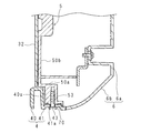
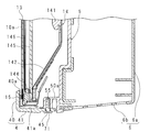
次に、被覆部材4の下板41の両端部に設けた各第1貫通孔43を、第1長辺部50aに設けた、挿入孔52に隣接する各第1螺子穴53に整合させ、図10に示すように螺子70により固定する。また、被覆部材4の下板41に設けた各第2貫通孔45を、第1長辺部50aに設けた、係合孔54に隣接する各第2螺子穴55に整合させ、図11に示すように螺子71により固定する。これにより、被覆部材4及びミドルキャビネット5は、螺子止めにより固定される。ここで、第1貫通孔43及び第2貫通孔45は、いわゆるバカ穴であり、位置合わせのために余裕をもたせた寸法とされている。
係合体44及び第2貫通孔45が隣接し、係合孔54及び第2螺子穴55が隣接している。したがって、螺子止めの位置が、係合体44及び係合孔54に隣接している。これにより、各係合体44を各係合孔54に挿入することにより、被覆部材4の撓み等による影響を低減して、第2貫通孔45及び第2螺子穴55における螺子71による固定を容易に行うことができる。また、同様に、ピン42及び第1貫通孔43が隣接し、挿入孔52及び第1螺子穴53が隣接しているので、ピン42を挿入孔52に挿入することにより、被覆部材4の撓み等による影響を低減して、第1貫通孔43及び第1螺子穴53における螺子70による固定を容易に行うことができる。
第1貫通孔43及び第2貫通孔45の周縁部には、平坦な座部が設けられており、螺子止め後に第1長辺部50aに密着するので、被覆部材4及びミドルキャビネット5を位置ずれなく強固に固定することができる。これにより、被覆部材4及び表示面10aの隙間を低減することができ、表示装置1の美観が向上する。
ここで、被覆部材4の表示部10への取り付けについて説明する。まず、平坦な作業台(不図示)に、表示部10を、表示面10aを下向きにして、被覆部材4が取り付けられる長辺部が前記作業台からはみ出すように載置し、上側からミドルキャビネット5を被せて取り付ける。ミドルキャビネット5の取り付け後、上述の如く被覆板を組み付ける。
このとき、各係合体44が係合孔54に挿入されて係合し、作業者が被覆部材4から手を放したとしても落下等しないので、被覆部材4が表示部10に仮止めされる。
以上の如く構成された表示装置1においては、図示しない制御部により動作の制御が行われる。表示装置1の使用者は、例えば、赤外線により表示装置1と通信するリモートコントローラ(以下、「リモコン」という)等の操作部を操作することにより、制御部に指示を送信することができる。
制御部の動作により、シャーシ140内の各LED141から出射した光が、拡散板145により拡散し、光学シート146により集束され、液晶パネル13の後面に照射される。液晶パネル13は、入射光を変調して透過し、前面である表示面10aに画像を表示する。表示装置1は、チューナ11により受信し、デコーダ12が復号したテレビジョン放送の放送波に基づいて、液晶パネル13の表示面10aに画像を表示し、テレビジョン受信機として機能する。また、表示面10aに表示される画像に伴って、発光部4bの点消灯等が行われる。
以上の構成によれば、表示装置1において、表示面10aを下向きとした状態、即ち、液晶パネル13にバックライト装置14を取り付ける際の姿勢のままで、被覆部材4を表示部10に仮止めすることができる。
これにより、被覆部材4をミドルキャビネット5に螺子70,71により固定する間に、被覆部材4が落下又は位置ずれ等することを防止できる。したがって、作業者は、表示部10に被覆部材4を容易に取り付けることができる。また、表示装置1の組み立て工数を低減することができ、表示装置1の製造が容易となる。また、係合体44及び係合孔54が複数あるので、被覆部材4の表示部10に対する位置ずれ及び落下等を良好に防止することができる。
また、被覆部材4は、表示装置1の使用時に下側に位置することとなる下板41だけで、螺子70,71を用いて表示部10に固定されるので、表示装置1の美観が向上する。また、図10及び図11に示すように、螺子70,71の螺子の頭部を座部に対応して設けられた凹部に収めることにより、正面から、螺子70,71が視認できなくなるので、より表示装置1の美観が向上する。被覆部材4は、前板40及び係合体44により表示部10を挟持しているので、被覆部材4及び表示面10aの隙間を低減することができ、表示装置1の美観が向上する。
なお、実施の形態に係る表示装置1は、テレビジョン受信機に用いられる構成でなく、インフォメーションディスプレイ、カーナビゲーションの表示画面又はパーソナルコンピュータに用いられる構成であってもよい。また、被覆部材4は、周縁部の表示面10a側を覆う面と、背面側に張り出しており、ピン42、第1貫通孔43、係合体44及び第2貫通孔45を有する第2面とを有していれば、板状部材でなくともよく、例えば、ブロック状部材であってもよい。更に、表示部10としては、液晶パネル13を用いる構成だけでなく、プラズマディスプレイ又は有機ELパネル等の表示パネルを用いる構成であってもよい。
本開示の一実施形態に係る表示装置(1)は、正面(10a)に画像を表示する表示部(10)と、該表示部(10)の周縁部の正面(10a)側を覆う第1面(40a)、及び該第1面(40a)から前記表示部(10)の背面側に張り出す第2面(41a)を有する被覆部材(4)と、前記表示部(10)の背面側に位置し、前記被覆部材(4)が固定される固定部材(5)と、前記第2面(41a)から突出する係合体(44)と、前記固定部材(5)に設けられ、前記係合体(44)に係合する係合孔(54)とを備えることを特徴とする。
本実施形態によれば、表示部(10)の正面(10a)を下向きとした場合であっても、係合体(44)が係合孔(54)に挿入されることにより、被覆部材(4)を表示部(10)に取り付けた状態を保持することができる。したがって、表示部(10)の正面(10a)が下向きである場合に、被覆部材(4)を表示部(10)に仮止めすることができる。これにより、被覆部材(4)を固定部材(5)に螺子等により固定する間に、被覆部材(4)が脱離又は落下等することを防止できる。以上より、表示部(10)に被覆部材(4)を容易に取り付けることができる。
本開示の一実施形態に係る表示装置(1)は、前記被覆部材(4)及び固定部材(5)は、前記周縁部に沿って延びており、前記第2面(41a)の両端部には、突起(42)が設けられており、前記固定部材(5)には、前記突起(42)が挿入される挿入孔(52)が設けられていることを特徴とする。
本実施形態によれば、挿入孔(52)に挿入される突起(42)が被覆部材(4)の端部に位置しているので、突起(42)を挿入孔(52)に挿入することにより、被覆部材(4)の表示部(10)に対する位置決めが容易となる。
本開示の一実施形態に係る表示装置(1)は、前記係合体(44)及び係合孔(54)は、前記周縁部に沿って複数設けられていることを特徴とする。
本実施形態によれば、被覆部材(4)の表示部(10)に対する位置ずれ及び落下等を良好に防止することができる。
本開示の一実施形態に係る表示装置(1)は、一の前記係合体(44)と、該一の係合体(44)に係合する一の前記係合孔(54)とは、前記被覆部材(4)及び固定部材(5)の前記周縁部に沿った方向への相対移動を規制することを特徴とする。
本実施形態によれば、一の係合体(44)を一の係合孔(54)に挿入することにより、被覆部材(4)の表示部(10)に対する位置ずれを良好に防止できる。
本開示の一実施形態に係る表示装置(1)は、前記係合体(44)には、前記第1面(40a)側に突設されている爪部(440)が設けられていることを特徴とする。
本実施形態によれば、爪部(440)により、係合体(44)及び係合孔(54)が係合し、被覆部材(4)の表示部(10)からの落下等を良好に防止することができる。
本開示の一実施形態に係る表示装置(1)は、前記被覆部材(4)及び係合体(44)は、前記表示部(10)を挟持していることを特徴とする。
本実施形態によれば、被覆部材(4)及び正面(10a)の隙間を低減することができ、美観が向上する。
本開示の一実施形態に係る表示装置(1)は、前記被覆部材(4)と固定部材(5)とは、螺子止めにより固定されていることを特徴とする。
本実施形態によれば、被覆部材(4)を固定部材(5)に容易に固定することができる。
本開示の一実施形態に係る表示装置(1)は、前記螺子止めの位置は、前記係合孔(54)に隣接していることを特徴とする。
本実施形態によれば、螺子止めの位置は夫々、係合体(44)又は係合孔(54)に隣接しているので、係合体(44)を係合孔(54)に挿入することにより、被覆部材(4)の撓み等の影響を低減して、螺子止めを容易に行うことができる。
本開示の一実施形態に係るに係るテレビジョン受信機は、上述の表示装置(1)と、テレビジョン放送を受信する受信部(11)とを備え、前記受信部(11)で受信したテレビジョン放送に基づいて前記表示部(10)に映像を表示するようにしてあることを特徴とする。
本実施形態によれば、上述の表示装置(1)を用いることにより、テレビジョン受信機において、被覆部材(4)を容易に表示部(10)に取り付けることができる。
今回開示された実施の形態はすべての点で例示であって、制限的なものではないと考えられるべきである。本発明の範囲は、上記した意味ではなく、請求の範囲によって示され、請求の範囲と均等の意味及び範囲内でのすべての変更が含まれることが意図される。即ち、請求項に示した範囲で適宜変更した技術的手段を組み合わせて得られる実施形態も本発明の技術的範囲に含まれる。
1 表示装置
11 チューナ(受信部)
10 表示部
10a 表示面(正面)
4 被覆部材
40a 一面(第1面)
41a 一面(第2面)
42 ピン(突起)
43 第1貫通孔
44 係合体
440 爪部
45 第2貫通孔
5 ミドルキャビネット(固定部材)
52 挿入孔
53 第1螺子穴
54 係合孔
55 第2螺子穴
70,71 螺子
11 チューナ(受信部)
10 表示部
10a 表示面(正面)
4 被覆部材
40a 一面(第1面)
41a 一面(第2面)
42 ピン(突起)
43 第1貫通孔
44 係合体
440 爪部
45 第2貫通孔
5 ミドルキャビネット(固定部材)
52 挿入孔
53 第1螺子穴
54 係合孔
55 第2螺子穴
70,71 螺子
Claims (9)
- 正面に画像を表示する表示部と、
該表示部の周縁部の正面側を覆う第1面、及び該第1面から前記表示部の背面側に張り出す第2面を有する被覆部材と、
前記表示部の背面側に位置し、前記被覆部材が固定される固定部材と、
前記第2面から突出する係合体と、
前記固定部材に設けられ、前記係合体に係合する係合孔と
を備えることを特徴とする表示装置。 - 前記被覆部材及び固定部材は、前記周縁部に沿って延びており、
前記第2面の両端部には、突起が設けられており、
前記固定部材には、前記突起が挿入される挿入孔が設けられている
ことを特徴とする請求項1に記載の表示装置。 - 前記係合体及び係合孔は、前記周縁部に沿って複数設けられていることを特徴とする請求項1又は請求項2に記載の表示装置。
- 一の前記係合体と、該一の係合体に係合する一の前記係合孔とは、前記被覆部材及び固定部材の前記周縁部に沿った方向への相対移動を規制することを特徴とする請求項3に記載の表示装置。
- 前記係合体には、前記第1面側に突設されている爪部が設けられていることを特徴とする請求項1から請求項3までのいずれか一つに記載の表示装置。
- 前記被覆部材及び係合体は、前記表示部を挟持していることを特徴とする請求項1から請求項5までのいずれか一つに記載の表示装置。
- 前記被覆部材と固定部材とは、螺子止めにより固定されていることを特徴とする請求項1から請求項6までのいずれか一つに記載の表示装置。
- 前記螺子止めの位置は、前記係合孔に隣接していることを特徴とする請求項7に記載の表示装置。
- 請求項1から請求項8までのいずれか1つに記載の表示装置と、
テレビジョン放送を受信する受信部と
を備え、
前記受信部で受信したテレビジョン放送に基づいて前記表示部に映像を表示するようにしてあることを特徴とするテレビジョン受信機。
Applications Claiming Priority (2)
| Application Number | Priority Date | Filing Date | Title |
|---|---|---|---|
| JP2017041028A JP6685255B2 (ja) | 2017-03-03 | 2017-03-03 | 表示装置及びテレビジョン受信機 |
| JP2017-041028 | 2017-03-03 |
Publications (1)
| Publication Number | Publication Date |
|---|---|
| WO2018159196A1 true WO2018159196A1 (ja) | 2018-09-07 |
Family
ID=63371224
Family Applications (1)
| Application Number | Title | Priority Date | Filing Date |
|---|---|---|---|
| PCT/JP2018/003038 Ceased WO2018159196A1 (ja) | 2017-03-03 | 2018-01-30 | 表示装置及びテレビジョン受信機 |
Country Status (2)
| Country | Link |
|---|---|
| JP (1) | JP6685255B2 (ja) |
| WO (1) | WO2018159196A1 (ja) |
Citations (7)
| Publication number | Priority date | Publication date | Assignee | Title |
|---|---|---|---|---|
| JP2001215896A (ja) * | 2000-02-02 | 2001-08-10 | Seiko Epson Corp | 電気光学装置及びその製造方法並びに電子機器 |
| JP2007025004A (ja) * | 2005-07-12 | 2007-02-01 | Sony Corp | 画像表示装置 |
| US20090122220A1 (en) * | 2007-11-07 | 2009-05-14 | Kyung-Rok Ko | Liquid crystal display device and method of manufacturing the same |
| US20090225252A1 (en) * | 2008-03-05 | 2009-09-10 | Lg Display Co., Ltd. | Display device |
| JP2013102420A (ja) * | 2011-10-17 | 2013-05-23 | Funai Electric Co Ltd | 表示装置およびテレビジョン装置 |
| WO2014002856A1 (ja) * | 2012-06-25 | 2014-01-03 | シャープ株式会社 | 表示装置及びテレビジョン受信機 |
| EP3015907A1 (en) * | 2014-10-27 | 2016-05-04 | LG Electronics Inc. | Display apparatus |
Family Cites Families (2)
| Publication number | Priority date | Publication date | Assignee | Title |
|---|---|---|---|---|
| US9603266B2 (en) * | 2012-11-08 | 2017-03-21 | Sharp Kabushiki Kaisha | Display device |
| JP2016066953A (ja) * | 2014-09-25 | 2016-04-28 | シャープ株式会社 | 表示装置およびテレビジョン受信機 |
-
2017
- 2017-03-03 JP JP2017041028A patent/JP6685255B2/ja not_active Expired - Fee Related
-
2018
- 2018-01-30 WO PCT/JP2018/003038 patent/WO2018159196A1/ja not_active Ceased
Patent Citations (7)
| Publication number | Priority date | Publication date | Assignee | Title |
|---|---|---|---|---|
| JP2001215896A (ja) * | 2000-02-02 | 2001-08-10 | Seiko Epson Corp | 電気光学装置及びその製造方法並びに電子機器 |
| JP2007025004A (ja) * | 2005-07-12 | 2007-02-01 | Sony Corp | 画像表示装置 |
| US20090122220A1 (en) * | 2007-11-07 | 2009-05-14 | Kyung-Rok Ko | Liquid crystal display device and method of manufacturing the same |
| US20090225252A1 (en) * | 2008-03-05 | 2009-09-10 | Lg Display Co., Ltd. | Display device |
| JP2013102420A (ja) * | 2011-10-17 | 2013-05-23 | Funai Electric Co Ltd | 表示装置およびテレビジョン装置 |
| WO2014002856A1 (ja) * | 2012-06-25 | 2014-01-03 | シャープ株式会社 | 表示装置及びテレビジョン受信機 |
| EP3015907A1 (en) * | 2014-10-27 | 2016-05-04 | LG Electronics Inc. | Display apparatus |
Also Published As
| Publication number | Publication date |
|---|---|
| JP2018148374A (ja) | 2018-09-20 |
| JP6685255B2 (ja) | 2020-04-22 |
Similar Documents
| Publication | Publication Date | Title |
|---|---|---|
| JP5657763B2 (ja) | 表示装置、液晶表示装置 | |
| US9977176B2 (en) | Backlight device and display apparatus | |
| US20150055053A1 (en) | Display device and support member thereof | |
| US10775655B2 (en) | Display apparatus and back light unit included therein | |
| JP2019144305A (ja) | 表示装置及びテレビジョン受像機 | |
| JP6469580B2 (ja) | 照明装置及び表示装置 | |
| JP4333781B2 (ja) | 液晶モジュール | |
| WO2015076100A1 (ja) | 表示装置 | |
| WO2018159196A1 (ja) | 表示装置及びテレビジョン受信機 | |
| JP6483267B2 (ja) | 表示装置 | |
| JP6297731B1 (ja) | 表示装置及びテレビジョン受信機 | |
| JP4762003B2 (ja) | 表示装置 | |
| CN205640364U (zh) | 直下型背光源及电视接收机 | |
| JP2018045197A (ja) | 表示装置及びテレビジョン受信機 | |
| JP6557508B2 (ja) | 表示装置及びテレビジョン受信機 | |
| JP2017005348A (ja) | 表示装置及びテレビジョン受信機 | |
| JP2020187983A (ja) | 光拡散レンズ、及びバックライト装置 | |
| JP2016208473A (ja) | 表示装置、及びテレビジョン受信機 | |
| JP2016066009A (ja) | 表示装置 | |
| WO2018155065A1 (ja) | 表示装置及びテレビジョン受信機 | |
| JP2017009796A (ja) | 表示装置及びテレビジョン受信機 | |
| JP2010113096A (ja) | 表示装置 | |
| JP6379064B2 (ja) | 反射シート、バックライト装置、表示装置及びテレビジョン受信機 | |
| WO2018051899A1 (ja) | 表示装置及びテレビジョン受信機 | |
| JP2015065174A (ja) | 直下型バックライトおよびテレビジョン受像機 |
Legal Events
| Date | Code | Title | Description |
|---|---|---|---|
| 121 | Ep: the epo has been informed by wipo that ep was designated in this application |
Ref document number: 18761631 Country of ref document: EP Kind code of ref document: A1 |
|
| NENP | Non-entry into the national phase |
Ref country code: DE |
|
| 122 | Ep: pct application non-entry in european phase |
Ref document number: 18761631 Country of ref document: EP Kind code of ref document: A1 |