WO2018158874A1 - 非接触給電システム、送電設備、及び受電設備 - Google Patents
非接触給電システム、送電設備、及び受電設備 Download PDFInfo
- Publication number
- WO2018158874A1 WO2018158874A1 PCT/JP2017/008076 JP2017008076W WO2018158874A1 WO 2018158874 A1 WO2018158874 A1 WO 2018158874A1 JP 2017008076 W JP2017008076 W JP 2017008076W WO 2018158874 A1 WO2018158874 A1 WO 2018158874A1
- Authority
- WO
- WIPO (PCT)
- Prior art keywords
- power
- power transmission
- airtight
- supply system
- circuit
- Prior art date
- Legal status (The legal status is an assumption and is not a legal conclusion. Google has not performed a legal analysis and makes no representation as to the accuracy of the status listed.)
- Ceased
Links
Images




Classifications
-
- B—PERFORMING OPERATIONS; TRANSPORTING
- B60—VEHICLES IN GENERAL
- B60L—PROPULSION OF ELECTRICALLY-PROPELLED VEHICLES; SUPPLYING ELECTRIC POWER FOR AUXILIARY EQUIPMENT OF ELECTRICALLY-PROPELLED VEHICLES; ELECTRODYNAMIC BRAKE SYSTEMS FOR VEHICLES IN GENERAL; MAGNETIC SUSPENSION OR LEVITATION FOR VEHICLES; MONITORING OPERATING VARIABLES OF ELECTRICALLY-PROPELLED VEHICLES; ELECTRIC SAFETY DEVICES FOR ELECTRICALLY-PROPELLED VEHICLES
- B60L53/00—Methods of charging batteries, specially adapted for electric vehicles; Charging stations or on-board charging equipment therefor; Exchange of energy storage elements in electric vehicles
- B60L53/10—Methods of charging batteries, specially adapted for electric vehicles; Charging stations or on-board charging equipment therefor; Exchange of energy storage elements in electric vehicles characterised by the energy transfer between the charging station and the vehicle
- B60L53/12—Inductive energy transfer
-
- H—ELECTRICITY
- H02—GENERATION; CONVERSION OR DISTRIBUTION OF ELECTRIC POWER
- H02J—ELECTRIC POWER NETWORKS; CIRCUIT ARRANGEMENTS OR SYSTEMS FOR SUPPLYING OR DISTRIBUTING ELECTRIC POWER; SYSTEMS FOR STORING ELECTRIC ENERGY
- H02J50/00—Circuit arrangements or systems for wireless supply or distribution of electric power
- H02J50/10—Circuit arrangements or systems for wireless supply or distribution of electric power using inductive coupling
- H02J50/12—Circuit arrangements or systems for wireless supply or distribution of electric power using inductive coupling of the resonant type
-
- B—PERFORMING OPERATIONS; TRANSPORTING
- B60—VEHICLES IN GENERAL
- B60L—PROPULSION OF ELECTRICALLY-PROPELLED VEHICLES; SUPPLYING ELECTRIC POWER FOR AUXILIARY EQUIPMENT OF ELECTRICALLY-PROPELLED VEHICLES; ELECTRODYNAMIC BRAKE SYSTEMS FOR VEHICLES IN GENERAL; MAGNETIC SUSPENSION OR LEVITATION FOR VEHICLES; MONITORING OPERATING VARIABLES OF ELECTRICALLY-PROPELLED VEHICLES; ELECTRIC SAFETY DEVICES FOR ELECTRICALLY-PROPELLED VEHICLES
- B60L2200/00—Type of vehicles
- B60L2200/32—Waterborne vessels
Definitions
- This invention relates to a non-contact power supply system, a power transmission facility, and a power reception facility.
- Patent Document 1 describes a non-contact power feeding system that includes a power feeding coil provided on the ground and a power receiving coil positioned above the power feeding coil and supplies power from the power feeding coil to the power receiving coil by non-contact power feeding. ing.
- the non-contact power supply system is provided so as to cover the power supply coil, and includes a flexible cover that occupies the space between the power supply coil and the power reception coil by being inflated.
- the space between the power feeding coil and the power receiving coil is occupied through a specific shape that can exclude foreign substances existing in the wire.
- Patent Document 2 describes a non-contact power feeding system that appropriately cools a coil that generates heat by non-contact power feeding in water.
- a power receiving side pad including a power receiving coil of a power receiving device provided in an underwater moving body and a power transmitting side pad including a power transmitting coil of a power transmitting device are provided to face each other via a liquid.
- Non-contact power feeding is performed using magnetic coupling with the coil.
- a spacer member having a gap for forming a liquid flow is provided between the power reception side pad and the power transmission side pad.
- the present invention has been made based on such a viewpoint, and an object thereof is to provide a non-contact power feeding system, a power transmission facility, and a power receiving facility that are waterproof and can safely perform non-contact power feeding.
- One of the present invention for achieving the above object is a non-contact power feeding system, a power transmission circuit for transmitting power by non-contact power feeding, a power receiving circuit for receiving power transmitted from the power transmission circuit, An airtight sheet provided to cover the power transmission surface of the power transmission circuit, the power transmission circuit is provided in the airtight space formed by the airtight sheet, and the airtight sheet is flexible and waterproof. It is made of a material having a predetermined outer shape by the internal pressure of the gas filled in the airtight space.
- the power transmission circuit is provided in an airtight space formed by an airtight sheet made of a material having flexibility and waterproofness, sufficient waterproofness can be ensured with a simple configuration.
- the airtight sheet is maintained in a predetermined outer shape by the internal pressure of the gas filled in the airtight space, and when the power transmission part of the power transmission circuit is brought close to the power reception part of the power reception circuit during non-contact power feeding,
- a flexible airtight sheet expanded by internal pressure is interposed as a buffer, and accidents such as damage due to contact can be prevented and safe non-contact power feeding can be performed.
- Another aspect of the present invention is the contactless power feeding system, wherein the airtight sheet has a curvature of a predetermined region facing the power transmission surface of the power transmission circuit in a state where the airtight sheet is maintained in the predetermined outer shape. It is assumed that the curvature is smaller than the curvature around the predetermined area.
- the power transmission circuit and the power reception circuit can be disposed at close positions (for example, the power transmission coil and the power reception coil) at the time of the non-contact power feeding, and the non-contact power feeding can be performed efficiently.
- the contactless power supply system wherein the power transmission circuit includes a power transmission coil that configures a power transmission side resonance circuit, and the power transmission surface is a power transmission surface of the power transmission coil. To do.
- Another aspect of the present invention is the above contactless power supply system, wherein a power transmission circuit that transmits power by contactless power supply, a power reception circuit that receives power transmitted from the power transmission circuit, and the power reception circuit
- a power transmission circuit that transmits power by contactless power supply
- a power reception circuit that receives power transmitted from the power transmission circuit
- the power reception circuit An airtight sheet provided so as to cover the power receiving surface, and the power receiving circuit is provided in the airtight space formed by the airtight sheet, and the airtight sheet is made of a material having flexibility and waterproofness.
- the predetermined outer shape is maintained by the internal pressure of the gas filled in the airtight space.
- the power receiving circuit is provided in an airtight space formed by an airtight sheet made of a material having flexibility and waterproofness, waterproofness can be reliably ensured while having a simple configuration.
- the airtight sheet is maintained in a predetermined outer shape by the internal pressure of the gas filled in the airtight space, and when the power transmission part of the power transmission circuit is brought close to the power reception part of the power reception circuit during non-contact power supply, the internal pressure between the two
- the flexible air-tight sheet expanded by the step is interposed as a buffer, and non-contact power feeding can be performed safely.
- Another aspect of the present invention is the contactless power feeding system, wherein the airtight sheet has a curvature of a predetermined region facing the power receiving surface of the power receiving circuit in a state where the airtight sheet is maintained in the predetermined outer shape. It is assumed that the curvature is smaller than the curvature around the predetermined area.
- the power transmission circuit and the power reception circuit (for example, the power transmission coil and the power reception coil) can be disposed at close positions during the non-contact power feeding, and the non-contact power feeding can be performed efficiently.
- the power receiving circuit includes a power receiving coil constituting a power receiving side resonance circuit, and the power receiving surface is a power receiving surface of the power receiving coil.
- Another aspect of the present invention is the non-contact power feeding system, wherein the airtight sheet is provided to protrude outside the ship at a predetermined position on a side surface of the ship.
- an airtight sheet can be easily provided at a predetermined position on a side surface of a ship by retrofitting.
- a mechanism of a non-contact power feeding system having both waterproofness and safety can be easily applied to an existing ship. Can be introduced.
- Another aspect of the present invention is the contactless power supply system, wherein the airtight sheet is provided in the ship so that a part of a surface thereof constitutes a part of a side surface of the ship.
- the airtight sheet can be provided in the ship.
- the airtight sheet in the ship so that a part of the surface thereof constitutes a part of the side surface of the ship, it is possible to efficiently perform non-contact power feeding with other ships. it can.
- Another aspect of the present invention is the non-contact power feeding system, wherein the airtight sheet is made of a resin or rubber having flexibility and waterproofness.
- Another aspect of the present invention is the non-contact power feeding system, wherein the airtight sheet has a gas injection valve for injecting gas into the airtight space.
- FIG. 1st embodiment It is a figure showing the schematic structure of the non-contact electric supply system of a 1st embodiment. It is a figure which shows the structure of the electrical part of power transmission equipment. It is a figure which shows the structure of the electrical part of a receiving device. It is a figure which shows a mode that gas is inject
- FIG. 1 shows a schematic configuration of a non-contact power feeding system 1 shown as the first embodiment.
- the non-contact power supply system 1 includes a power transmission facility 20 provided in a ship 2A that transmits power and a power reception facility 30 provided in a ship 2B that receives power.
- the ship 2A and the ship 2B are collectively referred to as the ship 2 as appropriate.
- the ship 2 is, for example, a large ship (tanker, ship, large passenger ship, large cargo ship, large fishing ship, etc.), a small ship (boat, yacht, anchor, small cargo ship, small fishing ship, etc.).
- the type is not limited.
- the ship 2A and the ship 2B may be the same type of ship or different types of ships.
- the ship 2A or the ship 2B is merely an example used on or in water, and the ship 2 may be other than the ship 2 such as a quay, a barge, a culture shelf, and the like.
- FIG. 2 shows the configuration of the electrical part of the power transmission facility 20.
- the power transmission facility 20 includes a power supply device 5 and a power transmission circuit 21.
- the power transmission circuit 21 includes a power transmission coil 211, a power transmission capacitor 212, and a control circuit 213.
- the power transmission coil 211 is obtained by winding a conductor wire such as a copper wire a predetermined number of times around a predetermined center point or winding axis, for example, a loop shape (circular, rectangular, concentric, etc.) Appearance shape such as spiral (including the case where the cross section is rectangular) is exhibited.
- the power transmission coil 211 and the power transmission capacitor 212 constitute a resonance circuit on the power transmission side.
- the control circuit 213 includes a processor (such as a microcomputer) and a driver circuit (such as a gate driver and a half bridge driver), and generates a drive current having a predetermined frequency supplied to the power transmission coil 211 based on the power supplied from the power supply device 5. Generate.
- a processor such as a microcomputer
- a driver circuit such as a gate driver and a half bridge driver
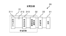
- FIG. 3 shows the configuration of the electrical part of the power receiving facility 30.
- the power receiving facility 30 includes a power receiving circuit 31, a charge / discharge control circuit 32, a storage battery 33, and a load 51.
- the power receiving circuit 31 includes a power receiving coil 311, a power receiving capacitor 312, and a rectifier circuit 313.
- the power receiving coil 311 is obtained by winding a conductor wire such as a copper wire a predetermined number of times around a predetermined center point or winding axis, for example, a loop shape (circular shape, rectangular shape, concentric circular shape, etc.) Appearance shape such as spiral (including the case where the cross section is rectangular) is exhibited.
- the power receiving coil 311 and the power receiving capacitor 312 constitute a power receiving side resonance circuit.
- the rectifying circuit 313 converts (rectifies) the AC power received by the power receiving circuit 31 into DC power and supplies the DC power to the storage battery 33.
- the charge / discharge control circuit 32 includes a processor (such as a microcomputer), a voltage sensor that measures a voltage between terminals of the storage battery 33, a current sensor that measures a current input to or output from the storage battery 33, and the like.
- the charge / discharge state (remaining amount of the storage battery 33, etc.) is monitored and the charge / discharge of the storage battery 33 is controlled.
- the storage battery 33 is, for example, a lithium ion secondary battery, a lithium polymer secondary battery, a lead storage battery, a nickel metal hydride battery, or a nickel cadmium battery.
- the electric power stored in the storage battery 33 is appropriately supplied to the load 51.
- the load 51 is, for example, various electric devices (navigation facilities, lighting, work machines, work robots, etc.) provided in the ship 2.
- the load 51 includes a motor or the like.
- a power unit is also included.
- the load 51 is an AC load, for example, a boost chopper or an inverter is provided between the storage battery 33 and the load 51 as appropriate.
- the power transmission circuit 21 is provided at a predetermined height position on the side surface 71 ⁇ / b> A of the ship 2 ⁇ / b> A, and the airtight sheet 11 ⁇ / b> A protruding outside the side surface 71 ⁇ / b> A is provided so as to cover the power transmission surface of the power transmission circuit 21.
- the power transmission surface of the power transmission circuit 21 is, for example, the power transmission surface of the power transmission coil 211 (for example, a surface perpendicular to the winding axis of the conducting wire of the power transmission coil 211).
- the airtight sheet 11A forms an airtight space 111A together with the side surface 71A, and the power transmission circuit 21 is provided in the airtight space 111A.
- the power transmission capacitor 212 and the control circuit 213 may be provided inside the airtight space 111A or outside the airtight space 111A. In this embodiment, it is assumed that at least the power transmission coil 211 is provided in the airtight space 111A.
- the control circuit 213, the power transmission capacitor 212, and the power supply device 5 may be provided, for example, on the deck 13A or the inboard 14A of the ship 2A.
- the wiring 6 that electrically connects the configuration provided inside the hermetic sheet 11A and the configuration provided outside the hermetic sheet 11A is provided, for example, along the side surface 71A of the ship 2A.
- the wiring 6 is provided so as not to affect the airtightness of the airtight space 111A.
- a part of the wiring 6 is constituted by a flat cable drawn from the inside of the airtight space 111A to the outside of the airtight space 111A through the bottom portion of the airtight sheet 11A.
- a part of the wiring 6 is constituted by a conductor having one end exposed in the airtight space 111A and the other end exposed outside the airtight space 111A.
- a part of the wiring 6 is constituted by a conductor having one end exposed in the airtight space 111A and the other end exposed inside the ship 2A.
- a power receiving circuit 31 is provided at a predetermined height position on the side surface 71B of the ship 2B, and an airtight sheet 11B protruding outside the side surface 71B is provided so as to cover the power receiving surface of the power receiving circuit 31. It has been.
- the power receiving surface of the power receiving circuit 31 is, for example, the power receiving surface of the power receiving coil 311 (for example, a surface perpendicular to the winding axis of the conducting wire of the power receiving coil 311).
- the airtight sheet 11B forms an airtight space 111B together with the side surface 71B, and the power receiving circuit 31 is provided in the airtight space 111B.
- the power receiving capacitor 312, the rectifier circuit 313, and the charge / discharge control circuit 32 may be provided inside the airtight space 111B or outside the airtight space 111B.
- the power receiving coil 311 is provided in the airtight space 111B.
- the charge / discharge control circuit 32, the power receiving capacitor 312 and the rectifier circuit 313 may be provided, for example, on the deck 13B or inboard 14B of the ship 2B.
- the wiring 7 that electrically connects the configuration provided inside the hermetic sheet 11B and the configuration provided outside the hermetic sheet 11B is provided, for example, along the side surface 71B of the ship 2B.
- the wiring 7 is provided so as not to affect the airtightness of the airtight space 111B.
- a part of the wiring 7 is constituted by a flat cable drawn out from the inside of the airtight space 111B to the outside of the airtight space 111B via the hem portion of the airtight sheet 11B.
- a part of the wiring 7 is constituted by a conductor having one end exposed in the airtight space 111B of the airtight sheet 11B and the other end exposed outside the airtight space 111B.
- a part of the wiring 7 is constituted by a conductor having one end exposed in the airtight space 111B and the other end exposed inside the ship 2B.
- the airtight sheet 11A is configured using a material (resin, rubber, or the like) that has a small amount of attenuation of power transmitted by non-contact power feeding (small shielding effect) and is excellent in flexibility and waterproofness.
- the airtight sheet 11A includes one or more gas sealing valves 12A.
- the airtight space 111A is filled with a gas such as air or an inert gas via the gas sealing valve 12A.
- the outer shape of the airtight sheet 11A is maintained by the internal pressure of the gas filled in the airtight space 111A.
- the space between the hem portion of the airtight sheet 11A and the side surface 71A of the ship 2A is securely sealed so that the gas filled in the airtight space 111A does not leak to the outside.
- the airtight sheet 11B is configured using a material (resin, rubber, or the like) that has a small amount of attenuation of power transmitted by non-contact power feeding (small shielding effect) and is excellent in flexibility and waterproofness.
- the airtight sheet 11B includes one or more gas sealing valves 12B.
- the airtight space 111B is filled with a gas such as air or an inert gas via the gas sealing valve 12B.
- the outer shape of the airtight sheet 11B is maintained by the internal pressure of the gas filled in the airtight space 111B.
- the space between the hem portion of the airtight sheet 11B and the side surface 71B of the ship 2B is securely sealed so that the gas filled in the airtight space 111B does not leak outside.
- the gas filling device 8 ⁇ / b> A (gas filling pump or the like) enters the airtight space 111 ⁇ / b> A via the gas feeding pipe 9 ⁇ / b> A and the gas sealing valve 12 ⁇ / b> A, and the gas filling device 8 ⁇ / b> B (gas filling pump or the like) A state is shown in which gas is injected into the airtight space 111B via the sealing valve 12B.
- the gas filling into the airtight space 111A and the airtight space 111B is performed, for example, from the respective decks 13A and 13B of the ships 2A and 2B and the insides 14A and 14B (for example, through the through holes provided in the side surfaces 71A and 71B).
- it may be performed from a gas filling device provided on another ship, a quay, or the like.
- a sensor for measuring the internal pressure of the airtight space 111A and the airtight space 111B in real time is provided so that when the internal pressure falls below a predetermined threshold, gas is automatically injected from the gas filling device into the airtight space 111A and the airtight space 111B. Also good.
- the airtight sheet 11A and the airtight sheet 11B inject gas into each of the airtight spaces 111A and 111B to keep the inside of each of the airtight spaces 111A and 111B at a predetermined internal pressure threshold value or more, thereby transmitting from the power transmission circuit 21 to the power reception circuit 31.
- the outer shape is maintained so that the power transmission by the non-contact power feeding is efficiently performed.
- the outer shape is, for example, a shape in which the overlapping area of the power transmission surface of the power transmission coil 221 and the power reception surface of the power reception coil 311 is as large as possible (for example, the magnetic flux output from the power transmission surface is as much as possible). It is a shape that often enters the power receiving surface).
- the airtight sheet 11A and the airtight sheet 11B are substantially hemispherical as a whole by injecting gas into the respective airtight spaces 111A and 111B and keeping the interior at a predetermined internal pressure or higher.
- the outer shape is maintained such that the curvature of the predetermined area facing the power transmission surface of the power transmission coil 221 and the power reception surface of the power reception coil 311 is smaller than the curvature around the predetermined area.
- the airtight sheet 11A and the airtight sheet 11B are configured so that corner portions are not formed (or the corner portions are reduced as much as possible) when maintaining the predetermined outer shape. It is preferable.
- FIG. 5 shows a schematic configuration of the non-contact power feeding system 1 shown as the second embodiment.
- the non-contact electric power feeding system 1 of 2nd Embodiment differs in the structure of 11 A of airtight sheets, and the airtight sheet
- the other configuration of the non-contact power feeding system 1 shown as the second embodiment is basically the same as the configuration of the first embodiment.
- the airtight sheet 11A of the second embodiment is provided at a predetermined height position on the side surface 71A of the ship 2A.
- the airtight sheet 11A of the second embodiment uses a material (resin, rubber, etc.) that has a small amount of attenuation of power transmitted by non-contact power feeding (small shielding effect) and is excellent in flexibility and waterproofness. It is configured.
- the airtight sheet 11A of the second embodiment does not protrude from the side surface 71A to the outside of the ship like the airtight sheet 11A of the first embodiment, but protrudes into the ship.
- a part of the surface of the airtight sheet 11A constitutes a part of the side surface 71A of the ship 2A.
- power is transmitted by non-contact power supply like the side surface 71A of the ship 2A made of a steel plate or the like. The power that is generated is not greatly attenuated.
- the boundary between the airtight sheet 11A and the side surface 71A is securely sealed (sealed) so that water does not enter the ship from the outside.
- the hermetic sheet 11A of the second embodiment includes one or more gas sealing valves 12A at predetermined positions.
- the outer shape of the airtight sheet 11A is maintained by the internal pressure of the gas filled in the airtight space 111A.
- the airtight space 111A of the airtight sheet 11A is filled with a gas such as air or an inert gas from a gas filling device 8A provided in the inboard 14A, for example, via the air supply pipe 9A and the gas sealing valve 12A.
- the airtight sheet 11B of the second embodiment is provided at a predetermined height position on the side surface 71B of the ship 2B.
- the hermetic sheet 11B of the second embodiment uses a material (resin, rubber, etc.) that has a small amount of attenuation of power transmitted by non-contact power feeding (small shielding effect) and is excellent in flexibility and waterproofness. It is configured.
- the airtight sheet 11B of the second embodiment does not protrude from the side surface 71B to the outside of the ship like the airtight sheet 11B of the first embodiment, but protrudes into the ship.
- a part of the surface of the airtight sheet 11B constitutes a part of the side surface 71B of the ship 2B.
- power is transmitted by non-contact power supply like the side surface 71B of the ship 2B made of a steel plate or the like. The power that is generated is not greatly attenuated.
- the boundary portion between the airtight sheet 11B and the side surface 71B is securely sealed (sealed) so that water does not enter the ship from the outside.
- the hermetic sheet 11B of the second embodiment includes one or more gas sealing valves 12B at predetermined positions.
- the outer shape of the airtight sheet 11B is maintained by the internal pressure of the gas filled in the airtight space 111B.
- An airtight space 111B of the airtight sheet 11B is filled with a gas such as air or an inert gas from a gas filling device 8B provided in the ship 14B, for example, via an air supply pipe 9B and a gas sealing valve 12B.
- the power transmission circuit 21 is formed by the airtight sheet 11A made of a material having flexibility and waterproofness.
- the airtight sheet 11A provided in the airtight space 111A is maintained in a predetermined outer shape by the internal pressure of the gas filled in the airtight space 111A. Therefore, when the power transmission coil 211 of the power transmission circuit 21 is brought close to the power reception coil 311 of the power reception circuit 31 during non-contact power feeding, a flexible airtight sheet 11A that is expanded by the internal pressure is interposed between the two as a buffer, so that the Contact power feeding can be performed.
- the receiving circuit 31 is provided in the airtight space 111B formed of the airtight sheet
- the airtight sheet 11B is maintained in a predetermined outer shape by the internal pressure of the gas filled in the airtight space 111B. Therefore, when the power transmission coil 211 of the power transmission circuit 21 is brought close to the power reception coil 311 of the power reception circuit 31 during non-contact power feeding, a flexible airtight sheet 11B that is expanded by the internal pressure is interposed between the two as a buffer, so that the Contact power feeding can be performed.
- Non-contact power feeding system 2A, 2B ship, 5 power supply, 6 wiring, 7 wiring, 8A, 8B gas filling device, 11A, 11B airtight sheet, 111A, 111B, airtight space, 12A, 12B gas sealing valve, 13A, 13B deck, 14A, 14B inboard, 71A, 71B side, 20 power transmission equipment, 21 power transmission circuit, 211 power transmission coil, 212 power transmission capacitor, 213 control circuit, 30 power reception equipment, 31 power reception circuit, 311 power reception coil, 312 power reception capacitor, 313 Rectifier circuit, 32 storage batteries, 51 loads
Landscapes
- Engineering & Computer Science (AREA)
- Power Engineering (AREA)
- Computer Networks & Wireless Communication (AREA)
- Transportation (AREA)
- Mechanical Engineering (AREA)
- Charge And Discharge Circuits For Batteries Or The Like (AREA)
Abstract
非接触給電システムは、非接触給電により電力を送電する送電回路と、送電回路から送られてくる電力を受電する受電回路と、送電回路の送電面を覆うように設けられる気密シートと、を備え、送電回路は、気密シートによって形成される気密空間内に設けられ、気密シートは、可撓性及び防水性を有する素材からなり、気密空間に充填されている気体の内圧によって所定の外形形状に維持される。また非接触給電システムは、受電回路の受電面を覆うように設けられる気密シートを備え、受電回路は、気密シートにより形成される気密空間内に設けられ、気密シートは、可撓性及び防水性を有する素材からなり、気密空間に充填されている気体の内圧によって所定の外形形状に維持される。
Description
この発明は、非接触給電システム、送電設備、及び受電設備に関する。
特許文献1には、地上に設けられた給電コイルと、給電コイルの上方に位置する受電コイルとを具備し、給電コイルから受電コイルに非接触給電によって電力供給を行う非接触給電システムについて記載されている。非接触給電システムは、給電コイルを覆うように設けられ、膨張することにより給電コイルと受電コイルとの間の空間を占拠する柔軟性カバーを具備し、柔軟性カバーは、膨張時に、自らの上に存在する異物を排除し得る特定形状を経て給電コイルと受電コイルとの間の空間を占拠する。
特許文献2には、水中において非接触給電により発熱したコイルを適切に冷却する非接触給電システムについて記載されている。非接触給電システムは、水中移動体に設けられた受電装置の受電コイルを含む受電側パッドと送電装置の送電コイルを含む送電側パッドとが液体を介して対向して設けられ、受電コイルと送電コイルとの間の磁気的な結合を用いて非接触給電を行う。受電側パッドと送電側パッドとの間には、液体の流れを形成するための隙間を有するスペーサ部材が設けられている。
例えば、非接触給電により2つの船舶の間で電力伝送を行う場合には、送電回路の送電コイルと受電回路の受電コイルとを水面に近い位置や水中で接近させる必要があり、送電コイルや受電コイルについて十分な防水性が要求される。また送電コイルと受電コイルとを近づける際は接触による破損等の事故を防ぐために何らかの安全策を講じる必要がある。
本発明はこうした観点に基づきなされたもので、防水性を備えかつ安全に非接触給電を行うことが可能な、非接触給電システム、送電設備、及び受電設備を提供することを目的としている。
上記目的を達成するための本発明の一つは、非接触給電システムであって、非接触給電により電力を送電する送電回路と、前記送電回路から送られてくる電力を受電する受電回路と、前記送電回路の送電面を覆うように設けられる気密シートと、を備え、前記送電回路は、前記気密シートによって形成される前記気密空間に設けられ、前記気密シートは、可撓性及び防水性を有する素材からなり、前記気密空間に充填されている気体の内圧によって所定の外形形状に維持される。
本発明によれば、送電回路が、可撓性及び防水性を有する素材からなる気密シートによって形成される気密空間に設けられるので、簡素な構成でありながら十分な防水性を確保することができる。また気密シートは、気密空間に充填されている気体の内圧によって所定の外形形状に維持されており、非接触給電に際して送電回路の送電部を受電回路の受電部に接近させた際、両者の間に内圧によって膨張した柔軟な気密シートが緩衝体として介在し、接触による破損等の事故を防いで安全に非接触給電を行うことができる。
本発明の他の一つは、上記非接触給電システムであって、前記気密シートは、前記所定の外形形状に維持された状態において、前記送電回路の送電面と対峙する所定領域の曲率が当該所定領域の周囲の曲率よりも小さいこととする。
本発明によれば、非接触給電に際して送電回路と受電回路とを(例えば、送電コイルと受電コイルとを)近い位置に配置することができ、効率よく非接触給電を行うことができる。
本発明の他の一つは、上記非接触給電システムであって、前記送電回路は、送電側の共振回路を構成する送電コイルを含み、前記送電面は前記送電コイルの送電面であることとする。
本発明の他の一つは、上記非接触給電システムであって、非接触給電により電力を送電する送電回路と、前記送電回路から送られてくる電力を受電する受電回路と、前記受電回路の受電面を覆うように設けられる気密シートと、を備え、前記受電回路は、前記気密シートにより形成される前記気密空間に設けられ、前記気密シートは、可撓性及び防水性を有する素材からなり、前記気密空間に充填されている気体の内圧によって所定の外形形状に維持される。
本発明によれば、受電回路が、可撓性及び防水性を有する素材からなる気密シートによって形成される気密空間に設けられるので、簡素な構成でありながら防水性を確実に確保することができる。また気密シートは、気密空間に充填されている気体の内圧によって所定の外形形状に維持され、非接触給電に際して送電回路の送電部を受電回路の受電部に接近させた際、両者の間に内圧によって膨張した柔軟な気密シートが緩衝体として介在し、安全に非接触給電を行うことができる。
本発明の他の一つは、上記非接触給電システムであって、前記気密シートは、前記所定の外形形状に維持された状態において、前記受電回路の受電面と対峙する所定領域の曲率が当該所定領域の周囲の曲率よりも小さいこととする。
本発明によれば、非接触給電に際して送電回路と受電回路と(例えば、送電コイルと受電コイルと)を近い位置に配置することができ、効率よく非接触給電を行うことができる。
本発明の他の一つは、上記非接触給電システムであって、前記受電回路は、受電側の共振回路を構成する受電コイルを含み、前記受電面は前記受電コイルの受電面である。
本発明の他の一つは、上記非接触給電システムであって、前記気密シートは、船舶の側面の所定位置に前記船舶の外側に突出して設けられる。
本発明によれば、例えば、気密シートを船舶の側面の所定位置に後付けで容易に設けることができ、例えば、防水性と安全性とを兼ね備えた非接触給電システムの仕組みを既存の船舶に容易に導入することができる。
本発明の他の一つは、上記非接触給電システムであって、前記気密シートは、その表面の一部が船舶の側面の一部を構成するように前記船舶の船内に設けられる。
このように気密シートは、船舶の船内に設けることができる。またこのように、気密シートを、その表面の一部が船舶の側面の一部を構成するように船舶の内部に設けることで、他の船舶との間で効率よく非接触給電を行うことができる。
本発明の他の一つは、上記非接触給電システムであって、前記気密シートは、可撓性及び防水性を有する樹脂又はゴムを素材とする。
本発明の他の一つは、上記非接触給電システムであって、前記気密シートは、前記気密空間に気体を注入するためのガス注入弁を有する。
その他、本願が開示する課題、及びその解決方法は、発明を実施するための形態の欄、及び図面により明らかにされる。
本発明によれば、防水性を備えかつ安全に非接触給電を行うことが可能な非接触給電システムを実現することができる。
以下、実施形態について図面とともに説明する。
[第1実施形態]
図1に第1実施形態として示す非接触給電システム1の概略的な構成を示している。非接触給電システム1は、電力を送電する側の船舶2Aに設けられる送電設備20と、電力を受電する側の船舶2Bに設けられる受電設備30とを含む。尚、以下の説明において、船舶2A及び船舶2Bのことを船舶2と適宜総称する。
図1に第1実施形態として示す非接触給電システム1の概略的な構成を示している。非接触給電システム1は、電力を送電する側の船舶2Aに設けられる送電設備20と、電力を受電する側の船舶2Bに設けられる受電設備30とを含む。尚、以下の説明において、船舶2A及び船舶2Bのことを船舶2と適宜総称する。
船舶2は、例えば、大型船(タンカー、艦船、大型客船、大型貨物船、大型漁船等)、小型船(ボート、ヨット、筏、小型貨物船、小型漁船等)等であるが、船舶2の種類は限定されない。また船舶2A及び船舶2Bは同種の船舶であってもよいし、異種の船舶であってもよい。また船舶2A又は船舶2Bは水上もしくは水中で使用されるものの一例に過ぎず、船舶2は、例えば、岸壁、はしけ、養殖棚等のように船舶2以外のものであってもよい。
図2に送電設備20の電気的な部分の構成を示している。同図に示すように、送電設備20は、電源装置5及び送電回路21を備える。
送電回路21は、送電コイル211、送電コンデンサ212、及び制御回路213を備える。送電コイル211は、例えば、銅線等の導体線を所定の中心点又は巻回軸の周りに所定回数巻回したものであり、例えば、ループ状(円状、矩形状、同心円状等)、螺旋状(断面が矩形状場合を含む)等の外観形状を呈する。送電コイル211及び送電コンデンサ212は送電側の共振回路を構成する。制御回路213は、プロセッサ(マイクロコンピュータ等)、及びドライバ回路(ゲートドライバ、ハーフブリッジドライバ等)を含み、電源装置5から供給される電力に基づき、送電コイル211に供給する所定周波数の駆動電流を生成する。
図3に受電設備30の電気的な部分の構成を示している。同図に示すように、受電設備30は、受電回路31、充放電制御回路32、蓄電池33、及び負荷51を備える。受電回路31は、受電コイル311、受電コンデンサ312、及び整流回路313を備える。
受電コイル311は、例えば、銅線等の導体線を所定の中心点又は巻回軸の周りに所定回数巻回したものであり、例えば、ループ状(円状、矩形状、同心円状等)、螺旋状(断面が矩形状場合を含む)等の外観形状を呈する。受電コイル311及び受電コンデンサ312は受電側の共振回路を構成する。
整流回路313は、受電回路31が受電した交流電力を直流電力に変換(整流)して蓄電池33に供給する。
充放電制御回路32は、プロセッサ(マイクロコンピュータ等)、蓄電池33の端子間電圧を測定する電圧センサ、蓄電池33に入力又は出力される電流を計測する電流センサ等を備えて構成され、蓄電池33の充放電状態(蓄電池33の残量等)の監視や蓄電池33の充放電の制御を行う。
蓄電池33は、例えば、リチウムイオン二次電池、リチウムポリマー二次電池、鉛蓄電池、ニッケル水素電池、ニッケルカドミウム電池である。蓄電池33に蓄えられた電力は負荷51に適宜供給される。
負荷51は、例えば、船舶2に設けられている各種電気機器(航行設備、照明、作業機械、作業ロボット等)であり、例えば、船舶2が電動船である場合、負荷51にはモータ等の動力装置も含まれる。尚、負荷51が、例えば、交流負荷である場合には、蓄電池33と負荷51との間に適宜昇圧チョッパやインバータが設けられる。
図1に戻り、船舶2Aの側面71Aの所定高さ位置に送電回路21が設けられ、また送電回路21の送電面を覆うように、側面71Aの外側に突出する気密シート11Aが設けられている。送電回路21の上記送電面は、例えば、送電コイル211の送電面(例えば、送電コイル211の導線の巻回軸に垂直な面)である。
気密シート11Aは、側面71Aとともに気密空間111Aを形成し、送電回路21は気密空間111A内に設けられている。送電回路21の構成のうち、送電コンデンサ212や制御回路213は、夫々、気密空間111A内に設けてもよいし、気密空間111A外に設けてもよい。本実施形態では、少なくとも送電コイル211については気密空間111A内に設けられているものとする。制御回路213、送電コンデンサ212、及び電源装置5は、例えば、船舶2Aの甲板13Aや船内14Aに設けてもよい。
気密シート11Aの内側に設けられる構成と気密シート11Aの外側に設けられる構成とを電気的に接続する配線6は、例えば、船舶2Aの側面71Aに沿って設けられる。尚、上記配線6は、気密空間111Aの気密性に影響を与えないように設けられる。例えば、上記配線6の一部は、気密シート11Aの裾の部分を介して気密空間111A内から気密空間111A外に引き出されるフラットケーブルで構成される。また例えば、上記配線6の一部は、一端が気密空間111A内に露出し、他端が気密空間111A外に露出する導体で構成される。また例えば、上記配線6の一部は、一端が気密空間111A内に露出し、他端が船舶2Aの内部に露出する導体で構成される。
図1に示すように、船舶2Bの側面71Bの所定高さ位置には受電回路31が設けられ、また受電回路31の受電面を覆うように、側面71Bの外側に突出する気密シート11Bが設けられている。受電回路31の上記受電面は、例えば、受電コイル311の受電面(例えば、受電コイル311の導線の巻回軸に垂直な面)である。
気密シート11Bは、側面71Bとともに気密空間111Bを形成し、受電回路31は気密空間111B内に設けられている。受電回路31の構成のうち、受電コンデンサ312、整流回路313、及び充放電制御回路32は、夫々、気密空間111B内に設けてもよいし、気密空間111B外に設けてもよい。本実施形態では、少なくとも受電コイル311については気密空間111B内に設けられているものとする。充放電制御回路32、受電コンデンサ312、及び整流回路313は、例えば、船舶2Bの甲板13Bや船内14Bに設けてもよい。
気密シート11Bの内側に設けられる構成と気密シート11Bの外部に設けられる構成とを電気的に接続する配線7は、例えば、船舶2Bの側面71Bに沿って設けられる。尚、上記配線7は、気密空間111Bの気密性に影響を与えないように設けられる。例えば、上記配線7の一部は、気密シート11Bの裾の部分を介して気密空間111B内から気密空間111B外に引き出されるフラットケーブルで構成される。また例えば、上記配線7の一部は、一端が気密シート11Bの気密空間111B内に露出し、他端が気密空間111B外に露出する導体で構成される。また例えば、上記配線7の一部は、一端が気密空間111B内に露出し、他端が船舶2Bの内部に露出する導体で構成される。
[気密シート]
気密シート11Aは、非接触給電により送電される電力の減衰量が小さく(遮蔽効果が小さく)、可撓性、及び防水性に優れた素材(樹脂やゴム等)を用いて構成されている。気密シート11Aは一つ以上の気体封入弁12Aを備える。気密空間111A内には、気体封入弁12Aを介して、空気や不活性ガス等の気体が充填される。気密シート11Aの外形形状は、気密空間111Aに充填されている気体の内圧によって維持される。気密シート11Aの裾の部分と船舶2Aの側面71Aとの間は、気密空間111Aに充填されている気体が外部に漏れ出すことのないように確実に封止(シール)されている。
気密シート11Aは、非接触給電により送電される電力の減衰量が小さく(遮蔽効果が小さく)、可撓性、及び防水性に優れた素材(樹脂やゴム等)を用いて構成されている。気密シート11Aは一つ以上の気体封入弁12Aを備える。気密空間111A内には、気体封入弁12Aを介して、空気や不活性ガス等の気体が充填される。気密シート11Aの外形形状は、気密空間111Aに充填されている気体の内圧によって維持される。気密シート11Aの裾の部分と船舶2Aの側面71Aとの間は、気密空間111Aに充填されている気体が外部に漏れ出すことのないように確実に封止(シール)されている。
気密シート11Bは、非接触給電により送電される電力の減衰量が小さく(遮蔽効果が小さく)、可撓性、及び防水性に優れた素材(樹脂やゴム等)を用いて構成されている。気密シート11Bは一つ以上の気体封入弁12Bを備える。気密空間111B内には、気体封入弁12Bを介して、空気や不活性ガス等の気体が充填される。気密シート11Bの外形形状は、気密空間111Bに充填されている気体の内圧によって維持される。気密シート11Bの裾の部分と船舶2Bの側面71Bとの間は、気密空間111Bに充填されている気体が外部に漏れ出すことのないように確実に封止(シール)されている。
図4に、気体充填装置8A(気体充填ポンプ等)により送気パイプ9A及び気体封入弁12Aを介して気密空間111Aに、また気体充填装置8B(気体充填ポンプ等)により送気パイプ9B及び気体封入弁12Bを介して気密空間111Bに、夫々、気体を注入している様子を示す。尚、気密空間111A及び気密空間111Bへのガスの充填は、例えば、船舶2A,2Bの夫々の甲板13A,13Bや船内14A,14Bから(例えば、側面71A,側面71Bに設けた貫通孔を介して)行ってもよし、また例えば、他の船舶や岸壁等に設けられた気体充填装置から行ってもよい。また気密空間111Aや気密空間111Bの内圧をリアルタイムに計測するセンサを設け、内圧が所定の閾値以下になると気体充填装置から自動的にガスが気密空間111Aや気密空間111Bに注入されるようにしてもよい。
気密シート11A及び気密シート11Bは、夫々の気密空間111A,111Bに気体を注入して夫々の気密空間111A,111Bの内部を所定の内圧閾値以上に保つことにより、送電回路21から受電回路31への非接触給電による電力伝送が効率よく行われるような外形形状に維持される。上記外形形状は、例えば、送電コイル221の送電面と受電コイル311の受電面とを対峙させた際に両者が重なる面積がなるべく大きくなるような形状(例えば、送電面から出力される磁束がなるべく多く受電面に入るような形状)である。
本実施形態の場合には、気密シート11A及び気密シート11Bは、夫々の気密空間111A,111Bに気体を注入して夫々の内部を所定の内圧以上に保つことにより、その全体が略半球状に維持され、かつ、送電コイル221の送電面と受電コイル311の受電面と対峙する所定領域の曲率が当該所定領域の周囲の曲率よりも小さくなるような外形形状に維持される。このため、船舶2Aと船舶2Bとを近づけて気密シート11Aと気密シート11Bとを接近させた際、送電コイル211の送電面と受電コイル311の受電面と平行に維持しつつ、両者を十分に近い距離まで接近させることができ、効率よく非接触給電を行うことができる。尚、応力の集中を避けるため、気密シート11A及び気密シート11Bは、所定の上記外形形状に維持した際に角部となる部分が形成されないように(もしくは角部がなるべく少なくなるように)することが好ましい。
[第2実施形態]
図5に第2実施形態として示す非接触給電システム1の概略的な構成を示している。第2実施形態の非接触給電システム1は、気密シート11A及び気密シート11Bの構成が第1実施形態と異なる。第2実施形態として示す非接触給電システム1のその他の構成については基本的に第1実施形態の構成と同様である。
図5に第2実施形態として示す非接触給電システム1の概略的な構成を示している。第2実施形態の非接触給電システム1は、気密シート11A及び気密シート11Bの構成が第1実施形態と異なる。第2実施形態として示す非接触給電システム1のその他の構成については基本的に第1実施形態の構成と同様である。
第2実施形態の気密シート11Aは、船舶2Aの側面71Aの所定の高さ位置に設けられている。第2実施形態の気密シート11Aは、非接触給電により送電される電力の減衰量が小さく(遮蔽効果が小さく)、可撓性、及び防水性に優れた素材(樹脂やゴム等)を用いて構成されている。
同図に示すように、第2実施形態の気密シート11Aは、第1実施形態の気密シート11Aのように側面71Aから船外に突出するのではなく、船内に突出している。気密シート11Aの表面の一部は船舶2Aの側面71Aの一部を構成している。尚、このように、気密シート11Aの表面の一部が船舶2Aの側面71Aの一部を構成しているため、鋼板等で構成された船舶2Aの側面71Aのように非接触給電により送電される電力を大きく減衰させてしまうことがない。気密シート11Aと側面71Aとの境界部分は外部から船内に水が浸入しないように確実に封止(シール)されている。
第2実施形態の気密シート11Aは、その所定位置に一つ以上の気体封入弁12Aを備える。気密シート11Aの外形形状は、気密空間111Aに充填されている気体の内圧によって維持されている。気密シート11Aの気密空間111Aには、送気パイプ9A及び気体封入弁12Aを介して、例えば船内14Aに設けられた気体充填装置8Aから空気や不活性ガス等の気体が充填される。
第2実施形態の気密シート11Bは、船舶2Bの側面71Bの所定の高さ位置に設けられている。第2実施形態の気密シート11Bは、非接触給電により送電される電力の減衰量が小さく(遮蔽効果が小さく)、可撓性、及び防水性に優れた素材(樹脂やゴム等)を用いて構成されている。
同図に示すように、第2実施形態の気密シート11Bは、第1実施形態の気密シート11Bのように側面71Bから船外に突出するのではなく、船内に突出している。気密シート11Bの表面の一部は船舶2Bの側面71Bの一部を構成している。尚、このように、気密シート11Bの表面の一部が船舶2Bの側面71Bの一部を構成しているため、鋼板等で構成された船舶2Bの側面71Bのように非接触給電により送電される電力を大きく減衰させてしまうことがない。気密シート11Bと側面71Bとの境界部分は外部から船内に水が浸入しないように確実に封止(シール)されている。
第2実施形態の気密シート11Bは、その所定位置に一つ以上の気体封入弁12Bを備える。気密シート11Bの外形形状は、気密空間111Bに充填されている気体の内圧によって維持されている。気密シート11Bの気密空間111Bには、送気パイプ9B及び気体封入弁12Bを介して、例えば船内14Bに設けられた気体充填装置8Bから空気や不活性ガス等の気体が充填される。
[効果]
以上に説明したように、第1実施形態及び第2実施形態の非接触給電システム1にあっては、送電回路21が、可撓性及び防水性を有する素材からなる気密シート11Aによって形成される気密空間111Aに設けられ、また気密シート11Aは、気密空間111Aに充填されている気体の内圧によって所定の外形形状に維持される。そのため、非接触給電に際して送電回路21の送電コイル211を受電回路31の受電コイル311に接近させた際、両者の間に内圧によって膨張した柔軟な気密シート11Aが緩衝体として介在し、安全に非接触給電を行うことができる。
以上に説明したように、第1実施形態及び第2実施形態の非接触給電システム1にあっては、送電回路21が、可撓性及び防水性を有する素材からなる気密シート11Aによって形成される気密空間111Aに設けられ、また気密シート11Aは、気密空間111Aに充填されている気体の内圧によって所定の外形形状に維持される。そのため、非接触給電に際して送電回路21の送電コイル211を受電回路31の受電コイル311に接近させた際、両者の間に内圧によって膨張した柔軟な気密シート11Aが緩衝体として介在し、安全に非接触給電を行うことができる。
また第1実施形態及び第2実施形態の非接触給電システム1にあっては、受電回路31が、可撓性及び防水性を有する素材からなる気密シート11Bによって形成される気密空間111Bに設けられ、また気密シート11Bは、気密空間111Bに充填されている気体の内圧によって所定の外形形状に維持される。そのため、非接触給電に際して送電回路21の送電コイル211を受電回路31の受電コイル311に接近させた際、両者の間に内圧によって膨張した柔軟な気密シート11Bが緩衝体として介在し、安全に非接触給電を行うことができる。
ところで、以上の説明は、本発明の理解を容易にするためのものであり、本発明を限定するものではない。本発明は、その趣旨を逸脱することなく、変更、改良され得ると共に、本発明にはその等価物が含まれることは勿論である。
1 非接触給電システム、2A,2B 船舶、5 電源装置、6 配線、7 配線、8A,8B 気体充填装置、11A,11B 気密シート、111A,111B、気密空間、12A,12B 気体封入弁、13A,13B 甲板、14A,14B 船内、71A,71B 側面、20 送電設備、21 送電回路、211 送電コイル、212 送電コンデンサ、213 制御回路、30 受電設備、31 受電回路、311 受電コイル、312 受電コンデンサ、313 整流回路、32 蓄電池、51 負荷
Claims (14)
- 非接触給電により電力を送電する送電回路と、
前記送電回路から送られてくる電力を受電する受電回路と、
前記送電回路の送電面を覆うように設けられる気密シートと、
を備え、
前記送電回路は、前記気密シートによって形成される前記気密空間に設けられ、
前記気密シートは、可撓性及び防水性を有する素材からなり、前記気密空間に充填されている気体の内圧によって所定の外形形状に維持される、
非接触給電システム。 - 請求項1に記載の非接触給電システムであって、
前記気密シートは、前記所定の外形形状に維持された状態において、前記送電回路の送電面と対峙する所定領域の曲率が当該所定領域の周囲の曲率よりも小さい、
非接触給電システム。 - 請求項1に記載の非接触給電システムであって、
前記送電回路は、送電側の共振回路を構成する送電コイルを含み、前記送電面は前記送電コイルの送電面である、
非接触給電システム。 - 非接触給電により電力を送電する送電回路と、
前記送電回路から送られてくる電力を受電する受電回路と、
前記受電回路の受電面を覆うように設けられる気密シートと、
を備え、
前記受電回路は、前記気密シートによって形成される前記気密空間に設けられ、
前記気密シートは、可撓性及び防水性を有する素材からなり、前記気密空間に充填されている気体の内圧によって所定の外形形状に維持される、
非接触給電システム。 - 請求項4に記載の非接触給電システムであって、
前記気密シートは、前記所定の外形形状に維持された状態において、前記受電回路の受電面と対峙する所定領域の曲率が当該所定領域の周囲の曲率よりも小さい、
非接触給電システム。 - 請求項4に記載の非接触給電システムであって、
前記受電回路は、受電側の共振回路を構成する受電コイルを含み、前記受電面は前記受電コイルの受電面である、
非接触給電システム。 - 請求項1乃至6のいずれか一項に記載の非接触給電システムであって、
前記気密シートは、船舶の側面の所定位置に前記船舶の外側に突出して設けられる、
非接触給電システム。 - 請求項1乃至6のいずれか一項に記載の非接触給電システムであって、
前記気密シートは、その表面の一部が船舶の側面の一部を構成するように前記船舶の船内に設けられる、
非接触給電システム。 - 請求項1乃至6のいずれか一項に記載の非接触給電システムであって、
前記気密シートは、可撓性及び防水性を有する樹脂又はゴムを素材とする、
非接触給電システム。 - 請求項1乃至6のいずれか一項に記載の非接触給電システムであって、
前記気密シートは、前記気密空間に気体を注入するためのガス注入弁を有する、
非接触給電システム。 - 請求項1に記載の非接触給電システムにおける送電設備であって、
前記気密シートによって形成される気密空間に設けられる前記送電回路と、
可撓性及び防水性を有する素材からなり、前記気密空間に充填されている気体の内圧によって所定の外形形状に維持される前記気密シートと、
を備える、非接触給電システムの送電設備。 - 請求項11に記載の送電設備であって、
前記気密シートは、前記所定の外形形状に維持された状態において、前記送電回路の送電面と対峙する所定領域の曲率が当該所定領域の周囲の曲率よりも小さい、
非接触給電システムの送電設備。 - 請求項4に記載の非接触給電システムにおける受電設備であって、
前記気密シートによって形成される気密空間に設けられる前記受電回路と、
可撓性及び防水性を有する素材からなり、前記気密空間に充填されている気体の内圧によって所定の外形形状に維持される前記気密シートと、
を備える、非接触給電システムの受電設備。 - 請求項13に記載の受電設備であって、
前記気密シートは、前記所定の外形形状に維持された状態において、前記受電回路の受電面と対峙する所定領域の曲率が当該所定領域の周囲の曲率よりも小さい、
非接触給電システムの受電設備。
Priority Applications (2)
| Application Number | Priority Date | Filing Date | Title |
|---|---|---|---|
| JP2017558514A JP6292364B1 (ja) | 2017-03-01 | 2017-03-01 | 非接触給電システム、送電設備、及び受電設備 |
| PCT/JP2017/008076 WO2018158874A1 (ja) | 2017-03-01 | 2017-03-01 | 非接触給電システム、送電設備、及び受電設備 |
Applications Claiming Priority (1)
| Application Number | Priority Date | Filing Date | Title |
|---|---|---|---|
| PCT/JP2017/008076 WO2018158874A1 (ja) | 2017-03-01 | 2017-03-01 | 非接触給電システム、送電設備、及び受電設備 |
Publications (1)
| Publication Number | Publication Date |
|---|---|
| WO2018158874A1 true WO2018158874A1 (ja) | 2018-09-07 |
Family
ID=61628654
Family Applications (1)
| Application Number | Title | Priority Date | Filing Date |
|---|---|---|---|
| PCT/JP2017/008076 Ceased WO2018158874A1 (ja) | 2017-03-01 | 2017-03-01 | 非接触給電システム、送電設備、及び受電設備 |
Country Status (2)
| Country | Link |
|---|---|
| JP (1) | JP6292364B1 (ja) |
| WO (1) | WO2018158874A1 (ja) |
Cited By (2)
| Publication number | Priority date | Publication date | Assignee | Title |
|---|---|---|---|---|
| JP2022034812A (ja) * | 2020-08-19 | 2022-03-04 | ソフトバンク株式会社 | 充電システム |
| JP2024503551A (ja) * | 2021-01-20 | 2024-01-25 | ヅィー ミン ジョージ リー, | 船舶の充電システム |
Families Citing this family (1)
| Publication number | Priority date | Publication date | Assignee | Title |
|---|---|---|---|---|
| KR102528100B1 (ko) * | 2021-08-18 | 2023-05-03 | 양동규 | 선박 |
Citations (3)
| Publication number | Priority date | Publication date | Assignee | Title |
|---|---|---|---|---|
| JP2013005593A (ja) * | 2011-06-16 | 2013-01-07 | Ihi Corp | 給電装置及び給電システム |
| WO2013085030A1 (ja) * | 2011-12-07 | 2013-06-13 | 株式会社Ihi | 電力伝送システム |
| WO2015029247A1 (ja) * | 2013-09-02 | 2015-03-05 | 株式会社日立製作所 | 負極活物質被覆材並びにこれを用いた負極材料、負極、リチウムイオン二次電池及び電池システム |
Family Cites Families (1)
| Publication number | Priority date | Publication date | Assignee | Title |
|---|---|---|---|---|
| WO2015129247A1 (ja) * | 2014-02-25 | 2015-09-03 | 日本電気株式会社 | 無線給電装置、無線給電システムおよび無線給電方法 |
-
2017
- 2017-03-01 WO PCT/JP2017/008076 patent/WO2018158874A1/ja not_active Ceased
- 2017-03-01 JP JP2017558514A patent/JP6292364B1/ja active Active
Patent Citations (3)
| Publication number | Priority date | Publication date | Assignee | Title |
|---|---|---|---|---|
| JP2013005593A (ja) * | 2011-06-16 | 2013-01-07 | Ihi Corp | 給電装置及び給電システム |
| WO2013085030A1 (ja) * | 2011-12-07 | 2013-06-13 | 株式会社Ihi | 電力伝送システム |
| WO2015029247A1 (ja) * | 2013-09-02 | 2015-03-05 | 株式会社日立製作所 | 負極活物質被覆材並びにこれを用いた負極材料、負極、リチウムイオン二次電池及び電池システム |
Cited By (2)
| Publication number | Priority date | Publication date | Assignee | Title |
|---|---|---|---|---|
| JP2022034812A (ja) * | 2020-08-19 | 2022-03-04 | ソフトバンク株式会社 | 充電システム |
| JP2024503551A (ja) * | 2021-01-20 | 2024-01-25 | ヅィー ミン ジョージ リー, | 船舶の充電システム |
Also Published As
| Publication number | Publication date |
|---|---|
| JP6292364B1 (ja) | 2018-03-14 |
| JPWO2018158874A1 (ja) | 2019-03-07 |
Similar Documents
| Publication | Publication Date | Title |
|---|---|---|
| US11031820B2 (en) | Power transmitting device | |
| JP5334470B2 (ja) | 非接触式の船舶用給電システム、船舶及び船舶への給電方法 | |
| JP6292364B1 (ja) | 非接触給電システム、送電設備、及び受電設備 | |
| KR101236849B1 (ko) | 해저로봇 운용 시스템 및 그 방법 | |
| CN108988449B (zh) | 一种应用于水下航行器的海底电站系统 | |
| US9634524B2 (en) | Wireless power supply system | |
| EP3941782A1 (en) | Autonomous power battery exchange system for a marine vessel | |
| US9876364B2 (en) | Power receiving device, vehicle, and power transmission device | |
| EP2354075A1 (en) | Power feeding device and rubber tired gantry crane including the same | |
| US20090008994A1 (en) | Inductive coupling method for remote powering of sensors | |
| WO2016121089A1 (ja) | 電力供給システム、及び電力供給方法 | |
| US20210166855A1 (en) | Transmission coil and power transmission apparatus | |
| US11951848B2 (en) | Power transfer device and mooring area for inductively charging a water-bound vehicle | |
| CA3080605A1 (en) | System and method for supplying watercrafts, in particular ships, in a port with electrical power and loading and unloading device for a system and method of this type | |
| JP2018006672A (ja) | コイル装置 | |
| JP6710111B2 (ja) | 陸電受電システム及び陸電受電設備 | |
| KR102431067B1 (ko) | 수중로봇용 무인 유선 충전 시스템 | |
| JP2010239853A (ja) | 電気自動車用無接触充電器 | |
| RU2744064C1 (ru) | Устройство для бесконтактной передачи электроэнергии и информационных сигналов на подводный аппарат | |
| JP2015220853A (ja) | 非接触給電システム | |
| JP5823656B1 (ja) | 電力供給方法、及び電力供給システム | |
| CN216348662U (zh) | 一种船舶状态监控终端 | |
| KR102426893B1 (ko) | 하이브리드 선박 | |
| CN216003021U (zh) | 一种船舶状态监控系统 | |
| KR101671422B1 (ko) | 수중 내압용기 및 그 운용방법 |
Legal Events
| Date | Code | Title | Description |
|---|---|---|---|
| ENP | Entry into the national phase |
Ref document number: 2017558514 Country of ref document: JP Kind code of ref document: A |
|
| 121 | Ep: the epo has been informed by wipo that ep was designated in this application |
Ref document number: 17898882 Country of ref document: EP Kind code of ref document: A1 |
|
| NENP | Non-entry into the national phase |
Ref country code: DE |
|
| 122 | Ep: pct application non-entry in european phase |
Ref document number: 17898882 Country of ref document: EP Kind code of ref document: A1 |