WO2018155496A1 - 燃焼器及びガスタービン - Google Patents
燃焼器及びガスタービン Download PDFInfo
- Publication number
- WO2018155496A1 WO2018155496A1 PCT/JP2018/006243 JP2018006243W WO2018155496A1 WO 2018155496 A1 WO2018155496 A1 WO 2018155496A1 JP 2018006243 W JP2018006243 W JP 2018006243W WO 2018155496 A1 WO2018155496 A1 WO 2018155496A1
- Authority
- WO
- WIPO (PCT)
- Prior art keywords
- burner
- circumferential direction
- main
- burners
- combustor
- Prior art date
- Legal status (The legal status is an assumption and is not a legal conclusion. Google has not performed a legal analysis and makes no representation as to the accuracy of the status listed.)
- Ceased
Links
Images





Classifications
-
- F—MECHANICAL ENGINEERING; LIGHTING; HEATING; WEAPONS; BLASTING
- F23—COMBUSTION APPARATUS; COMBUSTION PROCESSES
- F23R—GENERATING COMBUSTION PRODUCTS OF HIGH PRESSURE OR HIGH VELOCITY, e.g. GAS-TURBINE COMBUSTION CHAMBERS
- F23R3/00—Continuous combustion chambers using liquid or gaseous fuel
- F23R3/42—Continuous combustion chambers using liquid or gaseous fuel characterised by the arrangement or form of the flame tubes or combustion chambers
- F23R3/46—Combustion chambers comprising an annular arrangement of several essentially tubular flame tubes within a common annular casing or within individual casings
-
- F—MECHANICAL ENGINEERING; LIGHTING; HEATING; WEAPONS; BLASTING
- F23—COMBUSTION APPARATUS; COMBUSTION PROCESSES
- F23R—GENERATING COMBUSTION PRODUCTS OF HIGH PRESSURE OR HIGH VELOCITY, e.g. GAS-TURBINE COMBUSTION CHAMBERS
- F23R3/00—Continuous combustion chambers using liquid or gaseous fuel
- F23R3/42—Continuous combustion chambers using liquid or gaseous fuel characterised by the arrangement or form of the flame tubes or combustion chambers
-
- F—MECHANICAL ENGINEERING; LIGHTING; HEATING; WEAPONS; BLASTING
- F23—COMBUSTION APPARATUS; COMBUSTION PROCESSES
- F23R—GENERATING COMBUSTION PRODUCTS OF HIGH PRESSURE OR HIGH VELOCITY, e.g. GAS-TURBINE COMBUSTION CHAMBERS
- F23R3/00—Continuous combustion chambers using liquid or gaseous fuel
- F23R3/28—Continuous combustion chambers using liquid or gaseous fuel characterised by the fuel supply
- F23R3/286—Continuous combustion chambers using liquid or gaseous fuel characterised by the fuel supply having fuel-air premixing devices
-
- F—MECHANICAL ENGINEERING; LIGHTING; HEATING; WEAPONS; BLASTING
- F23—COMBUSTION APPARATUS; COMBUSTION PROCESSES
- F23R—GENERATING COMBUSTION PRODUCTS OF HIGH PRESSURE OR HIGH VELOCITY, e.g. GAS-TURBINE COMBUSTION CHAMBERS
- F23R3/00—Continuous combustion chambers using liquid or gaseous fuel
- F23R3/28—Continuous combustion chambers using liquid or gaseous fuel characterised by the fuel supply
- F23R3/34—Feeding into different combustion zones
-
- F—MECHANICAL ENGINEERING; LIGHTING; HEATING; WEAPONS; BLASTING
- F23—COMBUSTION APPARATUS; COMBUSTION PROCESSES
- F23R—GENERATING COMBUSTION PRODUCTS OF HIGH PRESSURE OR HIGH VELOCITY, e.g. GAS-TURBINE COMBUSTION CHAMBERS
- F23R2900/00—Special features of, or arrangements for continuous combustion chambers; Combustion processes therefor
- F23R2900/00014—Reducing thermo-acoustic vibrations by passive means, e.g. by Helmholtz resonators
Definitions
- the present invention relates to a combustor and a gas turbine.
- This application claims priority based on Japanese Patent Application No. 2017-029640 filed in Japan on February 21, 2017, the contents of which are incorporated herein by reference.
- a gas turbine combustor may include a plurality of main burners having the same shape and arranged at equal intervals in the circumferential direction.
- Patent Document 1 in order to form a wide range of combustion flames and realize stability and low emission, the shape of the mixing passage with the air in the wake of the fuel supply nozzle is made different so that a flame with a short outer diameter is large. And a technique for forming an elongated flame is described.
- Patent Document 2 in a combustor including a plurality of swirlers having swirl shafts arranged in parallel to the central axis in the circumferential direction, shear generated when outer edges of swirl flows by adjacent swirlers merge is reduced, and NOx
- a technique is described in which a swirl flow is given to each swirler so that the swirl directions of adjacent swirlers are opposite to each other.
- the shape of the flame in the circumferential direction is uniform, and the axial length of the flame is also uniform in the circumferential direction.
- the main burner described in Patent Document 2 is arranged such that the turning direction is opposite between main burners adjacent in the circumferential direction.
- the flame formed by the main burner described in Patent Document 2 also becomes uniform in the circumferential direction.
- This invention provides a combustor and a gas turbine that can suppress the occurrence of combustion vibration while suppressing an increase in the number of steps involved in manufacturing a main burner.
- the combustor includes a first burner as a main burner that swirls the primary air to generate an air-fuel mixture, and swirls the primary air in a direction opposite to the first burner for mixing. And a second burner as a main burner for generating energy.
- a plurality of the main burners are arranged at intervals in the circumferential direction, and the first burner and the second burner are arranged in a non-periodic arrangement pattern over the entire circumference in the circumferential direction.
- the first burner according to the first aspect and the second burner may be arranged in an asymmetric arrangement pattern in the circumferential direction. Since the first burner and the second burner are not arranged rotationally symmetrically, it is possible to suppress a uniform flame in the circumferential direction.
- the center of gravity position of the overall heat generation rate of the plurality of main burners is offset from the center position in the circumferential direction. It may be arranged in an arrangement pattern. By offsetting the position of the center of gravity, which is based on the heat generation rate of the flame by each main burner, from the center position of the arrangement of the plurality of main burners, it is possible to suppress the balance of the flame in the circumferential direction and to suppress a uniform flame. .
- the first burner according to the first aspect and the second burner are in the direction of the radial flow generated at the boundary between the first burner and the second burner in the circumferential direction.
- the plurality of main burners arranged at intervals in the circumferential direction are composed of one or a plurality of main burners adjacent to each other in the circumferential direction. And when it divides
- the gas turbine includes the combustor according to any one of the first to fifth aspects. By comprising in this way, it can reduce that an operating state becomes unstable by combustion vibration.
- the combustor and the gas turbine it is possible to suppress the occurrence of combustion vibration while suppressing an increase in man-hours related to the production of the main burner.
- FIG. 4 shows schematic structure of the gas turbine in 1st embodiment of this invention. It is a figure which shows schematic structure of the combustor in 1st embodiment of this invention. It is a figure which shows arrangement
- the gas turbine 1 includes a compressor 2, a combustor 3, and a turbine 4.
- the compressor 2 compresses the air A to generate compressed air.
- the combustor 3 burns the fuel F in the compressed air generated by the compressor 2 to generate high-temperature and high-pressure combustion gas.
- the turbine 4 is driven by the combustion gas generated by the combustor 3 and converts the energy of the combustion gas into rotational energy.
- the compressor 2 includes a compressor rotor 6 and a compressor casing 7.
- the turbine 4 includes a turbine rotor 8 and a turbine casing 9.
- the compressor rotor 6 and the turbine rotor 8 are arranged in series and rotate around the rotation axis Ar.
- the turbine rotor 8 and the compressor rotor 6 are integrally connected.
- the compressor rotor 6 and the turbine rotor 8 constitute a gas turbine rotor 10.
- a rotor of a generator GEN is connected to the gas turbine rotor 10.
- the compressor casing 7 covers the compressor rotor 6 and rotatably supports the compressor rotor 6.
- the turbine casing 9 covers the turbine rotor 8 and rotatably supports the turbine rotor 8.
- the compressor casing 7 and the turbine casing 9 are connected.
- the compressor rotor 6 and the turbine rotor 8 constitute a gas turbine rotor 10.
- the combustor 3 is fixed to the gas turbine casing 11.
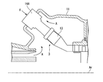
- the combustor 3 includes a combustion cylinder (or tail cylinder) 13 and a fuel ejector 14A.
- the combustion cylinder 13 burns the fuel F therein.
- the combustion cylinder 13 sends combustion gas obtained as a result of burning the fuel F to the turbine 4.
- the fuel ejector 14 ⁇ / b> A ejects fuel F and compressed air A into the combustion cylinder 13.
- the fuel ejector 14 ⁇ / b> A includes a pilot burner 15, a main burner 16, and a burner holding cylinder 17.
- the pilot burner 15 is disposed on the combustor axis Ac, and diffuses and burns fuel.
- the pilot burner 15 includes a pilot nozzle 18, a pilot burner cylinder 19, and a pilot swirler (not shown).
- the pilot nozzle 18 is formed to extend in the axial direction Da around the combustor axis Ac.
- the pilot nozzle 18 has, for example, an injection hole 18a for fuel injection at its downstream end.
- the pilot burner tube 19 includes a main body portion 21 and a cone portion 22.
- the main body 21 covers the outer periphery of the pilot nozzle 18.
- the cone portion 22 is disposed on the downstream side of the main body portion 21.
- the cone portion 22 is formed so as to gradually increase in diameter toward the downstream side.
- the pilot swirler (not shown) is arranged upstream of the position where the injection hole 18a of the pilot nozzle 18 is formed in the axial direction Da.
- This pilot swirler (not shown) turns compressed air (primary air) A flowing from the upstream side around the combustor axis Ac as a turning center.
- the pilot swirler (not shown) extends radially inward from the inner peripheral surface of the main body 21 of the pilot burner cylinder 19.
- a plurality of these pilot swirlers (not shown) are formed at intervals in the circumferential direction, for example.
- Compressed air A compressed by the compressor 2 flows into the pilot burner cylinder 19 of the pilot burner 15 from the upstream side.
- the fuel is injected from the injection hole 18 a of the pilot nozzle 18. This fuel is jetted from the pilot burner cylinder 19 toward the combustion cylinder 13 together with the compressed air A to which a swirl component is given by a pilot swirler (not shown), and diffusely burns in the combustion cylinder 13.
- a plurality of main burners 16 are provided. These main burners 16 are arranged so as to surround the outer periphery of the pilot burner 15. These main burners 16 premix and burn the fuel. These main burners 16 are arranged at intervals in the circumferential direction around the combustor axis Ac. More specifically, the main burners 16 are arranged at equal intervals in the circumferential direction around the combustor axis Ac.
- the main burner 16 includes a main nozzle 23, a main burner cylinder 24, and a main swirler 25.
- the main nozzle 23 extends in parallel with the combustor axis Ac. These main nozzles 23 have, for example, fuel injection holes 23a on the outer peripheral surface thereof.
- the main burner cylinder 24 covers the outer periphery of the main nozzle 23.
- the portion disposed on the inner side in the radial direction with the combustor axis Ac as the center also serves as a part of the pilot burner cylinder 19.
- the main swirler 25 turns the compressed air (primary air) A flowing from the upstream side with the main nozzle 23 as the turning center.
- the main swirler 25 extends from the inner peripheral surface of the main burner cylinder 24 toward the main nozzle 23.
- the main swirler 25 is provided in each of a plurality of main burners 16 provided.
- a plurality of main swirlers 25 are provided at intervals in the circumferential direction around the main nozzle 23.
- the burner holding cylinder 17 holds the pilot burner 15 and the main burner 16 described above. More specifically, the burner holding cylinder 17 holds the pilot burner 15 and the main burner 16 so that the plurality of main burners 16 surround the outer periphery of the pilot burner 15.
- Compressed air A compressed by the compressor 2 flows into the main burner cylinder 24 of the main burner 16 from the upstream side.
- the fuel F is injected from the injection hole 23 a of the main nozzle 23.
- This fuel F is mixed with the compressed air A to which the swirl component is given by the main swirler 25.
- the main swirler 25 may give a swirl component after the fuel F is injected into the compressed air A.
- the premixed gas in which the fuel and the compressed air A are mixed is ejected toward the combustion cylinder 13 and premixed and combusted in the combustion cylinder 13.
- the fuel ejector 14 includes a first burner 16 ⁇ / b> A as a main burner 16 whose turning directions by the main swirler 25 are opposite to each other, and a second burner 16 ⁇ / b> B as a main burner 16. .
- the first burner 16A and the second burner 16B have the same configuration except that the turning directions are opposite to each other.
- the pilot burner 15 is not shown.
- the main burner 16 used in this embodiment is only of two types, a first burner 16A and a second burner 16B.
- the turning direction is counterclockwise as viewed from the combustion cylinder 13 side.
- the second burner 16B in the first embodiment has a clockwise turning direction when viewed from the combustion cylinder 13 side.
- five first burners 16A are continuously arranged in the circumferential direction.
- three second burners 16B are continuously arranged in the circumferential direction.
- the fuel ejector 14A shown in FIG. 4 shows a case where eight main burners 16 are provided, but the number of the main burners 16 may be plural, for example, nine or more and seven or less. Also good.
- the positions of the eight main burners 16 in the circumferential direction are indicated by arrangement numbers “1” to “8”, respectively.
- the first burner 16A and the second burner 16B are arranged in an aperiodic arrangement pattern over the entire circumference in the circumferential direction in the fuel ejector 14A.
- the “periodic arrangement pattern” is a pattern in which the first burner 16 ⁇ / b> A and the second burner 16 ⁇ / b> B are arranged in the same order in the circumferential direction around the combustor axis Ac. It is only to be repeated.
- a periodic case when the first burner 16A and the second burner 16B are alternately arranged in the circumferential direction, only the first burner 16A is arranged, or only the second burner 16B is provided. The case where it arrange
- the arrangement pattern of the main burners 16 in the fuel injector 14A of the first embodiment is such that the first burner 16A and the second burner 16B are arranged around the combustor axis line Ac in the circumferential direction.
- the patterns in the order are not repeated with only the same pattern.
- the first burner 16A and the second burner 16B are arranged in an asymmetric arrangement pattern in the circumferential direction around the combustor axis Ac in the fuel injector 14A.
- the arrangement pattern asymmetric in the circumferential direction means that the first burner 16A and the second burner 16B are not arranged in the order of so-called rotational symmetry.
- the heat generation rate centroid and the combined vector are used as an example of an aperiodic index of the arrangement pattern of the first burner 16A and the second burner 16B. Only one of the vectors may be used.
- the first burner 16A and the second burner 16B include a combustor axis Ac in which the center of gravity g (see FIG. 5) of the overall heat generation rate of the plurality of main burners 16 is the center position in the circumferential direction in the fuel injector 14A.
- the center of gravity position g of the heat generation rate and the combustor axis line Ac substantially coincide.
- FIG. 5 “8-1”, “1-2”, “2-3”, “3-4”, “4-5”, “5-6”, and “6-7” are shown in FIG. It is a position corresponding to the arrangement number of the main burner 16 shown.
- “8-1” indicates a position between the positions “1” and “8” of the main burner 16.
- Three second burners 16B of the fuel ejector 14A of the first embodiment are continuously arranged in the circumferential direction.
- Five first burners 16A of the fuel ejector 14A are continuously arranged in the circumferential direction. Therefore, as shown in FIG. 5, the heat generation rate of the fuel injector 14A is biased in the circumferential direction and is offset outward at the position “8-1”. This bias in the heat generation rate is considered to be caused by the swirl direction at the boundary between the first burner 16A and the second burner 16B adjacent in the circumferential direction.
- the center-of-gravity position g of the heat generation rate of the fuel injector 14A is offset from the combustor axis Ac to the outside of the position “8-1”.
- the first burner 16A and the second burner 16B of the fuel ejector 14A are arranged in an arrangement pattern that is a combined vector that is larger than the unit vector.
- the unit vector is a vector corresponding to the direction of the radial flow generated at the boundary between the first burner 16A and the second burner 16B in the circumferential direction around the combustor axis Ac.
- the combined vector is a vector obtained by combining unit vectors in the fuel injector 14A. That is, the size of the combined vector obtained by combining the unit vectors corresponding to the direction of the radial flow generated at the boundary between the first burner 16A and the second burner 16B in the circumferential direction around the combustor axis Ac is the unit.
- the first burner 16 ⁇ / b> A and the second burner 16 ⁇ / b> B are arranged in an arrangement pattern that is larger than the size of the vector.
- the swirl flows act so as to cancel each other at the boundary between the adjacent main burners 16, so that the flow in the radial direction does not substantially occur.
- the swirl flows are directed in the same direction in the radial direction at the boundary between the adjacent main burners 16. That is, at the boundary between the first burner 16A and the second burner 16B, a flow that flows inward or outward in the radial direction around the combustor axis Ac is generated.
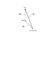
- the unit vector UA is derived from the (0, 0) coordinates.
- the (0,1) coordinate is reached.
- the unit vector UB extends from ( ⁇ 0.71, 0.71) coordinates to (0,0) coordinates.
- the sum of these unit vectors UA and UB (hereinafter referred to as a combined vector SV) is about 1.8. That is, the size of the combined vector SV of the unit vectors UA and UB is 1 or more.
- a plurality of main burners 16 arranged at intervals in the circumferential direction are divided in the circumferential direction, and are composed of a plurality of main burners 16 adjacent to each other in the circumferential direction.
- a “group” consisting of main burners 16 is formed.
- the fuel ejector 14A according to the first embodiment of the present invention is different from the other groups in the circumferential arrangement order (arrangement relationship) of the first burner 16A and the second burner 16B in at least one group. It has become.
- the fuel ejector 14A of the first embodiment if two main burners 16 adjacent in the circumferential direction are made into one group, four groups can be set in the circumferential direction.
- the arrangement number of the first group G1 composed of the two second burners 16B of “8” and “7” as the arrangement numbers of the main burner 16 and A second group G2 composed of one second burner 16B of "6" and "5" and one first burner 16A can be set.
- the third group G3 including only the first burners 16A having the arrangement numbers “4” and “3” of the main burner 16 and the two first burners 16A having the arrangement numbers “2” and “1”.
- the fourth group G4 can be set.
- the arrangement order of the first burner 16A and the second burner 16B in the circumferential direction is different from any of the second group G2 to the fourth group G4.
- the main burners 16 to be combined as a group are not limited to the arrangement numbers described above. Each group has, for example, the arrangement number “7” and “6”, “5” and “4”, “3” and “2”, “ The same thing can be said even if it is composed of “1” and “8”.
- the fuel ejector 14A of the first embodiment has eight main burners 16, the number of the plurality of main burners 16 that can be equally divided in the circumferential direction is two or four. Although illustration is omitted, the arrangement order of the first burner 16A and the second burner 16B in each group is different in the case of four as in the case of two. One group may include one main burner 16.
- the first burner 16A and the second burner 16B are arranged in a non-periodic arrangement pattern over the entire circumference in the circumferential direction centering on the combustor axis Ac.
- 14 A of fuel ejectors can form the flame which is not uniform in the circumferential direction, without using the multiple types of main burner from which an external shape differs.
- first burner 16A and the second burner 16B are not arranged rotationally symmetrically, it is possible to prevent the flame from becoming uniform in the circumferential direction.
- the balance of the flame in the circumferential direction is achieved by offsetting the center-of-gravity position g using the flame heat rate of each main burner 16 as an index from the combustor axis Ac that is the central position of the arrangement of the plurality of main burners 16. Can be prevented from breaking down into a uniform flame.
- the arrangement pattern in the circumferential direction of the first burner 16A and the second burner 16B is an arrangement pattern in which the magnitude of the combined vector SV is equal to or larger than the unit vector UA, the balance of the flame in the circumferential direction is lost. And can suppress a uniform flame.
- the plurality of main burners 16 arranged at intervals in the circumferential direction are divided in the circumferential direction into a group composed of one or a plurality of main burners 16 adjacent to each other in the circumferential direction and the same number of main burners 16.
- the arrangement relationship between the first burner 16A and the second burner 16B in at least one group is made different from that in the other groups. Therefore, it can suppress that a uniform flame is formed in the circumferential direction.
- the fuel ejector 14B in the second embodiment includes a first burner 16A and a second burner 16B as a plurality of main burners 16, similarly to the fuel ejector 14A of the first embodiment described above. And.
- the first burner 16A and the second burner 16B have the same configuration except that the turning directions are opposite to each other.
- the six first burners 16A of the fuel ejector 14B in the second embodiment are continuously arranged in the circumferential direction.
- Two second burners 16B of the fuel ejector 14B are continuously arranged in the circumferential direction.
- the fuel ejector 14B shown in FIG. 7 shows a case where the eight main burners 16 are provided as in FIG. 4, but the number of the main burners 16 may be plural, for example, nine or more, It may be 7 or less.
- the first burner 16A and the second burner 16B are disposed in a non-periodic arrangement pattern over the entire circumference in the circumferential direction, similarly to the fuel ejector 14A.
- the first burner 16A and the second burner 16B are further arranged in an arrangement pattern that is asymmetric in the circumferential direction about the combustor axis Ac (an arrangement pattern that is not rotationally symmetric).
- the center of gravity position g of the heat generation rate is offset from the combustor axis Ac, similarly to the fuel injector 14A of the first embodiment. Similar to the fuel injector 14A of the first embodiment, combined vectors obtained by combining unit vectors UA and UB corresponding to the direction of the radial flow generated at the boundary between the first burner 16A and the second burner 16B in the circumferential direction, respectively.
- the main burner 16 (first burner 16A, second burner 16B) of the fuel injector 14B is arranged in an arrangement pattern in which the magnitude of SV is greater than or equal to the magnitude of the unit vector UA (or UB).
- Fuel sprayer 14B can set four groups in the circumferential direction, if two main burners 16 adjacent in the circumferential direction are grouped. In this case, when viewed in one of the circumferential directions (for example, clockwise), the first group G1 composed of the two second burners 16B and the second group G2 to the fourth group G4 composed of the two first burners 16A. And can be set. In the first group G1, the arrangement order of the first burner 16A and the second burner 16B in the circumferential direction is different from any of the second group G2 to the fourth group G4.
- the fuel ejector 14B of the second embodiment also has eight main burners 16 as in the first embodiment. That is, the number of the plurality of main burners 16 that can be equally divided in the circumferential direction is two or four.
- the first burner 16A and the second burner 16B are non-periodic over the entire circumference in the circumferential direction centering on the combustor axis Ac. Arranged in an arrangement pattern. Thereby, the fuel ejector 14B can form a flame that is not uniform in the circumferential direction without using a plurality of types of main burners having different outer shapes. As a result, it is possible to suppress the occurrence of combustion vibration while suppressing an increase in the number of man-hours for manufacturing the main burner 16.
- first burner 16A and the second burner 16B are not arranged rotationally symmetrical, it is possible to suppress the flame from becoming uniform in the circumferential direction.
- the center of gravity position g using the flame heat generation rate by each main burner 16 as an index is offset from the combustor axis Ac which is the center position of the arrangement of the plurality of main burners 16. Therefore, the balance of the flame in the circumferential direction can be lost, and it can be suppressed that the flame becomes uniform in the circumferential direction.
- the arrangement pattern in the circumferential direction of the first burner 16A and the second burner 16B is an arrangement pattern in which the size of the combined vector SV is greater than or equal to the unit vector UA (or UB). Therefore, the balance of the flame in the circumferential direction can be lost, and it can be suppressed that the flame becomes uniform in the circumferential direction.
- the plurality of main burners 16 arranged at intervals in the circumferential direction are divided in the circumferential direction into a group composed of one or a plurality of main burners 16 adjacent to each other in the circumferential direction and the same number of main burners 16.
- the arrangement relationship between the first burner 16A and the second burner 16B in at least one group is made different from that in the other groups. Therefore, it can suppress that a flame is formed uniformly in the circumferential direction.
- the fuel ejector 14 ⁇ / b> C in the third embodiment includes a first burner 16 ⁇ / b> A and a second burner 16 ⁇ / b> B as a plurality of main burners 16, similarly to the fuel ejector 14 ⁇ / b> A of the first embodiment described above. It is equipped with.
- the first burner 16A and the second burner 16B have the same configuration except that the turning directions are opposite to each other.
- first burners 16A of the fuel ejector 14C in the third embodiment are continuously arranged in the circumferential direction.
- Four second burners 16B of the fuel ejector 14C are continuously arranged in the circumferential direction.
- the fuel ejector 14C shown in FIG. 8 shows a case where the eight main burners 16 are provided as in FIG. 4, but the number of the main burners 16 may be plural, for example, nine or more, It may be 7 or less.
- the first burner 16A and the second burner 16B of the fuel ejector 14C are arranged in a non-periodic arrangement pattern over the entire circumference in the circumferential direction, similarly to the fuel ejector 14A.
- the arrangement pattern of the first burner 16A and the second burner 16B of the third embodiment appears to be a periodic arrangement pattern at first glance.
- the periodic arrangement pattern referred to here is an arrangement pattern in which the first burner 16A and the second burner 16B are adjacent in the circumferential direction, for example, in the order of the first burner 16A and the second burner 16B in the circumferential direction.
- it means an arrangement pattern that appears twice or more while one arrangement pattern in the order of the second burner 16B and the first burner 16A makes one round in the circumferential direction.
- the first burner 16A and the second burner 16B of the fuel ejector 14B are arranged in a circumferentially asymmetric arrangement pattern (an arrangement pattern that is not rotationally symmetric) about the combustor axis Ac.
- the center-of-gravity position g of the heat generation rate of the fuel injector 14B is offset from the combustor axis Ac, similarly to the fuel injector 14A of the first embodiment.
- a combined vector SV obtained by combining unit vectors UA and UB corresponding to the direction of the radial flow generated at the boundary between the first burner 16A and the second burner 16B in the circumferential direction. Is larger than the unit vector UA (or UB).
- the main burners 16 (the first burner 16A and the second burner 16B) of the fuel ejector 14C are arranged in an arrangement pattern that becomes a combined vector SV that is equal to or larger than the unit vector UA (or UB).
- the size of the combined vector SV in the third embodiment is twice as large as the unit vector UA (or UB).
- Fuel sprayer 14B can set four groups in the circumferential direction, if two main burners 16 adjacent in the circumferential direction are grouped.
- the arrangement position of the main burner 16 is composed of one first burner 16A and one second burner 16B with “1” and “8”.
- the first group G1 the second group G2 composed of two first burners 16A
- the third group G3 composed of one second burner 16B and one first burner 16A
- the fourth group G4 can be set.
- the arrangement order of the first burner 16A and the second burner 16B in the circumferential direction is different from any of the second group G2 to the fourth group G4.
- the fuel injector 14C of the third embodiment also has eight main burners 16 as in the first embodiment. That is, the number of the plurality of main burners 16 that can be equally divided in the circumferential direction is two or four.
- the first burner 16A and the second burner 16B are arranged in a non-periodic arrangement pattern over the entire circumference in the circumferential direction centering on the combustor axis Ac. And are arranged.
- 14 C of fuel ejectors can form the flame which is not uniform in the circumferential direction, without using the multiple types of main burner from which an external shape differs.
- first burner 16A and the second burner 16B are not arranged rotationally symmetrical, it is possible to suppress the flame from becoming uniform in the circumferential direction.
- the center of gravity position g using the heat generation rate of the flame by each main burner 16 as an index is offset from the combustor axis Ac which is the center position of the arrangement of the plurality of main burners 16, the balance of the flame in the circumferential direction is improved. Breaking down, it can be suppressed that the flame becomes uniform.
- the circumferential direction of the first burner 16A and the second burner 16B is arranged as an arrangement pattern in which the magnitude of the combined vector SV is equal to or larger than the magnitude of the unit vector UA (or UB), the circumferential direction It is possible to suppress the balance of the flames and to make the flames uniform.
- the plurality of main burners 16 arranged at intervals in the circumferential direction are divided in the circumferential direction into a group composed of one or a plurality of main burners 16 adjacent to each other in the circumferential direction and the same number of main burners 16.
- the arrangement relationship between the first burner 16A and the second burner 16B in at least one group is made different from that in the other groups. Therefore, it can suppress that a flame is formed uniformly in the circumferential direction.
- the fuel injector 14D in the fourth embodiment includes a first burner 16A and a second burner 16B as a plurality of main burners 16, similarly to the fuel injector 14A of the first embodiment described above. And.
- the first burner 16A and the second burner 16B have the same configuration except that the turning directions are opposite to each other.
- first burners 16A are continuously arranged in the circumferential direction, and one second burner 16B is arranged. That is, only one of the plurality of main burners 16 arranged in the circumferential direction is the second burner 16B, and the other is the first burner 16A.
- the fuel injector 14D shown in FIG. 9 shows a case where eight main burners 16 are provided, as in FIG. However, the number of main burners 16 should just be two or more, for example, may be nine or more and seven or less.
- the first burner 16A and the second burner 16B of the fuel injector 14D are arranged in a non-periodic arrangement pattern over the entire circumference in the circumferential direction, similarly to the fuel injector 14A. Furthermore, the first burner 16A and the second burner 16B of the fuel ejector 14D are arranged in an asymmetric arrangement pattern (an arrangement pattern that is not rotationally symmetric) in the circumferential direction around the combustor axis Ac.
- center-of-gravity position g of the heat generation rate of the fuel injector 14D is offset from the combustor axis Ac, similarly to the fuel injector 1 ⁇ BR> SA of the first embodiment.
- the fuel ejector 14D if two main burners 16 adjacent in the circumferential direction are made into one group, four groups can be set in the circumferential direction.
- the first group G1 composed of one second burner 16B and one first burner 16A (arrangement number “8” of the main burner 16 and "7")
- the second group G2 to the fourth group G4 consisting of two first burners 16A (arrangement numbers "6" and "5", "4" and "3", “2” and the main burner 16) “1”) can be set.
- the arrangement order of the first burner 16A and the second burner 16B in the circumferential direction is different from any of the second group G2 to the fourth group G4.
- the fuel ejector 14D of the fourth embodiment also has eight main burners 16 as in the first embodiment. That is, the number of the plurality of main burners 16 that can be equally divided in the circumferential direction is two or four.
- the first burner 16A and the second burner 16B are arranged in a non-periodic arrangement pattern over the entire circumference in the circumferential direction centering on the combustor axis Ac. And are arranged.
- fuel ejector 14D can form the flame which is not uniform in the circumferential direction, without using the multiple types of main burner from which an external shape differs.
- first burner 16A and the second burner 16B are not arranged rotationally symmetrical, it is possible to suppress the flame from becoming uniform in the circumferential direction.
- the center of gravity position g using the flame heat generation rate by each main burner 16 as an index is offset from the combustor axis Ac which is the center position of the arrangement of the plurality of main burners 16. Therefore, it is possible to suppress the balance of the flame in the circumferential direction and to prevent the flame from becoming uniform.
- the plurality of main burners 16 arranged at intervals in the circumferential direction are divided in the circumferential direction into a group composed of one or a plurality of main burners 16 adjacent to each other in the circumferential direction and the same number of main burners 16.
- the arrangement relationship between the first burner 16A and the second burner 16B in at least one group is made different from that in the other groups. Therefore, it can suppress that a flame is formed uniformly in the circumferential direction.
- the “heat rate center of gravity” indicates the distance from the combustor axis Ac to the heat rate center of gravity.
- the arrangement of the main burner 16 in the fuel ejector 14A of the first embodiment described above is the case “6”.
- the arrangement of the main burner 16 in the fuel injector 14B of the second embodiment is the case “2”.
- the arrangement of the main burner 16 in the fuel injector 14C of the third embodiment is a case “13”.
- the arrangement of the main burner 16 in the fuel injector 14D of the fourth embodiment is the case “1”.
- the first burner 16A is indicated by “0”
- the second burner 16B is indicated by “1”.
- Case “0”, case “5”, case “20”, and case “22” in the above table are arranged in a periodic arrangement pattern over the entire circumference in the circumferential direction. Is arranged.
- Heat generation rate center of gravity The values of the heat generation rate centroids of case “0”, case “5”, case “20”, and case “22”, which are comparative examples, were all “0.0000”. On the other hand, in all cases except the comparative example, the value of the heat generation rate centroid is larger than “0.0000”.
- the solid line indicates the value of the heat generation rate centroid.
- the broken line indicates the size of the combined vector.
- the left end of the horizontal axis is the case “0”, and the right end is the case “22”. That is, on the horizontal axis, the case number increases toward the right side.
- a thick solid line extending in the horizontal direction is an example of a reference value for the value of the center of gravity of the heat generation rate and the magnitude of the combined vector.
- the size of the composite vector has a correlation with the value of the center of gravity of heat generation rate (solid line).
- the size of the combined vector and the value of the heat generation rate centroid are particularly high in the cases “2”, “6”, and “13” corresponding to the first, second, and third embodiments described above. . Although it is a numerical value lower than these cases “2”, “6”, and “13”, in the case “1” corresponding to the fourth embodiment, the size of the combined vector and the value of the heat generation rate centroid are: The value is sufficiently higher than “0”.
- the present invention is not limited to the configuration of each of the embodiments described above, and the design can be changed without departing from the gist thereof.
- the arrangement pattern is not limited to those in the first to fourth embodiments. That is, the arrangement pattern is not limited to the case “1”, “2”, “6”, “13”. For cases other than case “0”, case “5”, case “20”, and case “22” (arrangement pattern), cases other than case “1”, “2”, “6”, and “13” It may be an arrangement pattern.
- This invention can be applied to a combustor and a gas turbine. According to this invention, generation
- production of a combustion vibration can be suppressed, suppressing the man-hour concerning manufacture of a main burner increasing.
Landscapes
- Engineering & Computer Science (AREA)
- Chemical & Material Sciences (AREA)
- Combustion & Propulsion (AREA)
- Mechanical Engineering (AREA)
- General Engineering & Computer Science (AREA)
- Gas Burners (AREA)
Abstract
燃焼器は、一次空気を旋回させて混合気を生成する第一バーナー(16A)と、前記第一バーナー(16A)とは逆方向に一次空気を旋回させて混合気を生成する第二バーナー(16B)と、をメインバーナー(16)として備えている。前記メインバーナー(16)は、周方向に間隔をあけて複数配置され、前記周方向の全周に渡って非周期的な配置パターンで前記第一バーナー(16A)と前記第二バーナー(16B)とが配置されている。
Description
この発明は、燃焼器及びガスタービンに関する。
本願は、2017年2月21日に、日本に出願された特願2017-029640号に基づき優先権を主張し、その内容をここに援用する。
本願は、2017年2月21日に、日本に出願された特願2017-029640号に基づき優先権を主張し、その内容をここに援用する。
ガスタービンの燃焼器においては、周方向に等間隔で並べられた同一形状の複数のメインバーナーを備えている場合がある。
特許文献1には、広範囲な燃焼火炎を形成して安定性と低エミッションを実現するために、燃料供給ノズルの後流における空気との混合通路形状を異ならせることで、大外径の短い火炎と、細長い火炎を形成させる技術が記載されている。
特許文献2には、中心軸線に平行に配置された旋回軸を有するスワラーを周方向に複数備える燃焼器において、隣り合うスワラーによる旋回流の外縁が合流する際に生じるせん断を減少させて、NOxやCO排出の低減を図るために、各スワラーに対して、それぞれ隣り合うスワラーの旋回方向とは互いに反対方向となるような旋回流を与える技術が記載されている。
特許文献1には、広範囲な燃焼火炎を形成して安定性と低エミッションを実現するために、燃料供給ノズルの後流における空気との混合通路形状を異ならせることで、大外径の短い火炎と、細長い火炎を形成させる技術が記載されている。
特許文献2には、中心軸線に平行に配置された旋回軸を有するスワラーを周方向に複数備える燃焼器において、隣り合うスワラーによる旋回流の外縁が合流する際に生じるせん断を減少させて、NOxやCO排出の低減を図るために、各スワラーに対して、それぞれ隣り合うスワラーの旋回方向とは互いに反対方向となるような旋回流を与える技術が記載されている。
例えば、周方向に並んで配置された複数のメインバーナーによって形成される火炎が全て同じ特性の場合、周方向における火炎の形状が一様になり、火炎の軸方向長さも周方向で一様となる。
特許文献2に記載のメインバーナーは、周方向で隣接するメインバーナー同士で旋回方向が反対方向となるように配置されている。しかし、特許文献2に記載されたメインバーナーによって形成される火炎も、周方向で一様になってしまう。
このように周方向で一様な火炎が形成されると、メインバーナーに圧力変動が生じると、火炎が周方向で同じ変動を起こす。互いの火炎が同相で変動することで、燃焼器における発熱率の変動の振幅が大きくなり、燃焼振動が大きくなってしまう。
特許文献1に記載の燃焼器のように、火炎の形状を変化させるために外形が異なるメインバーナーを複数用いる場合、メインバーナーの製造に係る工数が増加してしまうという課題がある。
特許文献2に記載のメインバーナーは、周方向で隣接するメインバーナー同士で旋回方向が反対方向となるように配置されている。しかし、特許文献2に記載されたメインバーナーによって形成される火炎も、周方向で一様になってしまう。
このように周方向で一様な火炎が形成されると、メインバーナーに圧力変動が生じると、火炎が周方向で同じ変動を起こす。互いの火炎が同相で変動することで、燃焼器における発熱率の変動の振幅が大きくなり、燃焼振動が大きくなってしまう。
特許文献1に記載の燃焼器のように、火炎の形状を変化させるために外形が異なるメインバーナーを複数用いる場合、メインバーナーの製造に係る工数が増加してしまうという課題がある。
この発明は、メインバーナーの製造に係る工数が増加することを抑制しつつ、燃焼振動の発生を抑制することができる燃焼器及びガスタービンを提供する。
この発明の第一態様によれば、燃焼器は、一次空気を旋回させて混合気を生成するメインバーナーとしての第一バーナーと、前記第一バーナーとは逆方向に一次空気を旋回させて混合気を生成するメインバーナーとしての第二バーナーと、を備えている。前記メインバーナーは、周方向に間隔をあけて複数配置され、前記周方向の全周に渡って非周期的な配置パターンで前記第一バーナーと前記第二バーナーとが配置されている。
このように一次空気を旋回させる方向が互いに逆方向となる第一バーナーと第二バーナーとを周方向の全周に渡って非周期的に配置することで、周方向で一様な火炎となることを抑制できる。そのため、外形が異なる複数種のメインバーナーを用いる必要が無くなる。
したがって、メインバーナーの製造に係る工数が増加することを抑制しつつ、燃焼振動の発生を抑制することができる。
このように一次空気を旋回させる方向が互いに逆方向となる第一バーナーと第二バーナーとを周方向の全周に渡って非周期的に配置することで、周方向で一様な火炎となることを抑制できる。そのため、外形が異なる複数種のメインバーナーを用いる必要が無くなる。
したがって、メインバーナーの製造に係る工数が増加することを抑制しつつ、燃焼振動の発生を抑制することができる。
この発明の第二態様によれば、第一態様に係る第一バーナーと、第二バーナーとは、周方向で非対称な配置パターンで配置されていていてもよい。
第一バーナーと第二バーナーとを回転対称に配置しないため、周方向で一様な火炎となることを抑制できる。
第一バーナーと第二バーナーとを回転対称に配置しないため、周方向で一様な火炎となることを抑制できる。
この発明の第三態様によれば、第一態様に係る第一バーナーと、第二バーナーとは、複数の前記メインバーナーの全体の発熱率の重心位置が、前記周方向の中心位置からオフセットする配置パターンで配置されていてもよい。
各メインバーナーによる火炎の発熱率を指標とした重心位置を、複数のメインバーナーの配置の中心位置からオフセットさせることで、周方向における火炎のバランスを崩して一様な火炎となることを抑制できる。
各メインバーナーによる火炎の発熱率を指標とした重心位置を、複数のメインバーナーの配置の中心位置からオフセットさせることで、周方向における火炎のバランスを崩して一様な火炎となることを抑制できる。
この発明の第四態様によれば、第一態様に係る第一バーナーと、第二バーナーとは、周方向における前記第一バーナーと前記第二バーナーとの境界に生じる径方向の流れの向きに応じた単位ベクトルをそれぞれ合成した合成ベクトルの大きさが前記単位ベクトルの大きさ以上となる配置パターンで配置されていてもよい。
第一バーナーと第二バーナーとの周方向における配置パターンを、合成ベクトルの大きさが単位ベクトルの大きさ以上となる配置パターンとすることで、周方向における火炎のバランスを崩して一様な火炎となることを抑制できる。
第一バーナーと第二バーナーとの周方向における配置パターンを、合成ベクトルの大きさが単位ベクトルの大きさ以上となる配置パターンとすることで、周方向における火炎のバランスを崩して一様な火炎となることを抑制できる。
この発明の第五態様によれば、第一態様に係る燃焼器において、周方向に間隔をあけて配置された複数の前記メインバーナーを、一または互いに周方向に隣接する複数のメインバーナーからなり、且つ、同数のメインバーナーからなる群に周方向に分割した場合に、少なくとも一つの前記群における第一バーナー及び第二バーナーの配置関係が、他の前記群と異なるようにしても良い。
このように構成することで、周方向において一様な火炎が形成されることを抑制できる。
このように構成することで、周方向において一様な火炎が形成されることを抑制できる。
この発明の第六態様によれば、ガスタービンは、第一から第五態様の何れか一つの態様に係る燃焼器を備えている。
このように構成することで、燃焼振動により運転状態が不安定になることを低減できる。
このように構成することで、燃焼振動により運転状態が不安定になることを低減できる。
上記燃焼器及びガスタービンによれば、メインバーナーの製造に係る工数が増加することを抑制しつつ、燃焼振動の発生を抑制することができる。
(第一実施形態)
次に、この発明の第一実施形態における燃焼器及びガスタービンを図面に基づき説明する。
図1に示すように、ガスタービン1は、圧縮機2と、燃焼器3と、タービン4と、を備えている。
圧縮機2は、空気Aを圧縮して圧縮空気を生成する。燃焼器3は、燃料Fを圧縮機2で生成した圧縮空気中で燃焼させて高温高圧の燃焼ガスを生成する。タービン4は、燃焼器3により生成された燃焼ガスにより駆動され、燃焼ガスのエネルギーを回転エネルギーに変換する。
次に、この発明の第一実施形態における燃焼器及びガスタービンを図面に基づき説明する。
図1に示すように、ガスタービン1は、圧縮機2と、燃焼器3と、タービン4と、を備えている。
圧縮機2は、空気Aを圧縮して圧縮空気を生成する。燃焼器3は、燃料Fを圧縮機2で生成した圧縮空気中で燃焼させて高温高圧の燃焼ガスを生成する。タービン4は、燃焼器3により生成された燃焼ガスにより駆動され、燃焼ガスのエネルギーを回転エネルギーに変換する。
圧縮機2は、圧縮機ロータ6と、圧縮機ケーシング7と、を備えている。また、タービン4は、タービンロータ8と、タービンケーシング9と、を備えている。
圧縮機ロータ6とタービンロータ8とは、直列に配置されて回転軸線Arを中心に回転する。タービンロータ8と圧縮機ロータ6とは一体に連結されている。これら圧縮機ロータ6とタービンロータ8とによってガスタービンロータ10が構成されている。このガスタービンロータ10には、例えば、発電機GENのロータが連結されている。
圧縮機ロータ6とタービンロータ8とは、直列に配置されて回転軸線Arを中心に回転する。タービンロータ8と圧縮機ロータ6とは一体に連結されている。これら圧縮機ロータ6とタービンロータ8とによってガスタービンロータ10が構成されている。このガスタービンロータ10には、例えば、発電機GENのロータが連結されている。
圧縮機ケーシング7は、圧縮機ロータ6を覆うとともに圧縮機ロータ6を回転可能に支持している。タービンケーシング9は、タービンロータ8を覆うとともにタービンロータ8を回転可能に支持している。圧縮機ケーシング7とタービンケーシング9とは連結されている。これら圧縮機ロータ6とタービンロータ8とによってガスタービンロータ10が構成されている。このガスタービンケーシング11には、燃焼器3が固定されている。
図2に示すように、燃焼器3は、燃焼筒(又は尾筒)13と、燃料噴出器14Aとを備えている。燃焼筒13は、その内部で燃料Fを燃焼させる。燃焼筒13は、この燃料Fを燃焼させた結果得られる燃焼ガスをタービン4に送る。燃料噴出器14Aは、燃焼筒13内に燃料F及び圧縮空気Aを噴出する。
図3に示すように、燃料噴出器14Aは、パイロットバーナー15と、メインバーナー16と、バーナー保持筒17と、を備えている。
パイロットバーナー15は、燃焼器軸線Ac上に配置され、燃料を拡散燃焼させる。このパイロットバーナー15は、パイロットノズル18と、パイロットバーナー筒19と、パイロットスワラ(図示せず)と、を備えている。
パイロットバーナー15は、燃焼器軸線Ac上に配置され、燃料を拡散燃焼させる。このパイロットバーナー15は、パイロットノズル18と、パイロットバーナー筒19と、パイロットスワラ(図示せず)と、を備えている。
パイロットノズル18は、燃焼器軸線Acを中心として軸線方向Daに延びるように形成されている。このパイロットノズル18は、例えば、その下流側端部に燃料噴射用の噴射孔18aを有している。
パイロットバーナー筒19は本体部21と、コーン部22と、を備えている。本体部21は、パイロットノズル18の外周を覆っている。コーン部22は、本体部21の下流側に配置されている。このコーン部22は、下流側に向かって次第に拡径するように形成されている。
パイロットスワラ(図示せず)は、軸線方向Daでパイロットノズル18の噴射孔18aが形成されている位置よりも上流側に配置されている。このパイロットスワラ(図示せず)は、上流側から流れてきた圧縮空気(一次空気)Aを、燃焼器軸線Acを旋回中心にして旋回させる。パイロットスワラ(図示せず)は、パイロットバーナー筒19の本体部21の内周面から径方向内側に延びている。これらパイロットスワラ(図示せず)は、例えば、周方向に間隔をあけて複数形成されている。
圧縮機2で圧縮された圧縮空気Aは、上流側からパイロットバーナー15のパイロットバーナー筒19内に流入する。燃料は、パイロットノズル18の噴射孔18aから噴射される。この燃料は、パイロットスワラ(図示せず)により旋回成分を付与された圧縮空気Aと共に、パイロットバーナー筒19から燃焼筒13に向けて噴出され、燃焼筒13内で拡散燃焼する。
メインバーナー16は、複数設けられている。これらメインバーナー16は、パイロットバーナー15の外周を囲むように配置されている。これらメインバーナー16は、燃料を予混合燃焼させる。これらメインバーナー16は、燃焼器軸線Acを中心とした周方向に間隔をあけて配置されている。より具体的には、メインバーナー16は、燃焼器軸線Acを中心とした周方向に等間隔に配置されている。
メインバーナー16は、メインノズル23と、メインバーナー筒24と、メインスワラ25と、を備えている。
メインノズル23は、燃焼器軸線Acと平行に延びている。これらメインノズル23は、燃料噴射用の噴射孔23aを、例えば、その外周面に有している。
メインバーナー16は、メインノズル23と、メインバーナー筒24と、メインスワラ25と、を備えている。
メインノズル23は、燃焼器軸線Acと平行に延びている。これらメインノズル23は、燃料噴射用の噴射孔23aを、例えば、その外周面に有している。
メインバーナー筒24は、メインノズル23の外周を覆っている。図3に例示するメインバーナー筒24は、燃焼器軸線Acを中心とした径方向において内側に配置されている部分が、パイロットバーナー筒19の一部を兼ねている。
メインスワラ25は、上流側から流れてきた圧縮空気(一次空気)Aを、メインノズル23を旋回中心にして旋回させる。メインスワラ25は、メインバーナー筒24の内周面からメインノズル23に向かって延びている。メインスワラ25は、複数設けられたメインバーナー16にそれぞれ設けられている。メインスワラ25は、それぞれメインノズル23を中心とした周方向に間隔をあけて複数設けられている。
メインスワラ25は、上流側から流れてきた圧縮空気(一次空気)Aを、メインノズル23を旋回中心にして旋回させる。メインスワラ25は、メインバーナー筒24の内周面からメインノズル23に向かって延びている。メインスワラ25は、複数設けられたメインバーナー16にそれぞれ設けられている。メインスワラ25は、それぞれメインノズル23を中心とした周方向に間隔をあけて複数設けられている。
バーナー保持筒17は、上述したパイロットバーナー15及びメインバーナー16を保持している。より具体的には、バーナー保持筒17は、複数のメインバーナー16がパイロットバーナー15の外周を囲むように、パイロットバーナー15及びメインバーナー16を保持している。
圧縮機2で圧縮された圧縮空気Aは、上流側からメインバーナー16のメインバーナー筒24内に流入する。燃料Fは、メインノズル23の噴射孔23aから噴射される。この燃料Fは、メインスワラ25により旋回成分を付与された圧縮空気Aと混合される。メインスワラ25は、圧縮空気Aに燃料Fが噴射された後に、旋回成分を付与するようにしてもよい。これら燃料と圧縮空気Aとが混合された予混合気体は、燃焼筒13に向けて噴出され、燃焼筒13内で予混合燃焼する。
図4に示すように、燃料噴出器14は、メインスワラ25による旋回方向が互いに逆方向となるメインバーナー16としての第一バーナー16Aと、メインバーナー16としての第二バーナー16Bと、を備えている。これら第一バーナー16Aと第二バーナー16Bとは、旋回方向が互いに逆方向である点を除いて、同一の構成となっている。図4において、パイロットバーナー15の図示を省略している。この実施形態で用いるメインバーナー16は、第一バーナー16Aと、第二バーナー16Bとの二種類のみである。
この第一実施形態における第一バーナー16Aは、燃焼筒13側から見て旋回方向が左回りになっている。この第一実施形態における第二バーナー16Bは、燃焼筒13側から見て旋回方向が右回りになっている。この第一実施形態における燃料噴出器14Aは、5つの第一バーナー16Aが周方向に連続して配置されている。この第一実施形態における燃料噴出器14Aは、3つの第二バーナー16Bが周方向に連続して配置されている。図4に示す燃料噴出器14Aは、8つのメインバーナー16を備える場合を示しているが、メインバーナー16の数は、複数であればよく、例えば、9つ以上や、7つ以下であっても良い。図4において、周方向の8つのメインバーナー16の位置をそれぞれ配置番号「1」から「8」で示している。
第一バーナー16Aと第二バーナー16Bとは、燃料噴出器14Aにおいて、周方向の全周に渡って非周期的な配置パターンで配置されている。ここで、「周期的な配置パターン」とは、燃焼器軸線Acを中心として周方向に一周する間に、第一バーナー16Aと第二バーナー16Bとの配置されている順序のパターンが同一のパターンのみで繰り返されることである。周期的な場合の一例としては、第一バーナー16Aと第二バーナー16Bとが周方向に交互に配置されている場合や、第一バーナー16Aのみが配置される場合や、第二バーナー16Bのみが配置される場合などを挙げることができる。
つまり、この第一実施形態の燃料噴出器14Aにおけるメインバーナー16の配置パターンは、燃焼器軸線Acを中心として周方向に一周する間に、第一バーナー16Aと第二バーナー16Bとの配置されている順序のパターンが同一のパターンのみで繰り返されていない。
つまり、この第一実施形態の燃料噴出器14Aにおけるメインバーナー16の配置パターンは、燃焼器軸線Acを中心として周方向に一周する間に、第一バーナー16Aと第二バーナー16Bとの配置されている順序のパターンが同一のパターンのみで繰り返されていない。
第一バーナー16Aと第二バーナー16Bとは、燃料噴出器14Aにおいて燃焼器軸線Acを中心とした周方向で非対称な配置パターンで配置されている。この周方向で非対称な配置パターンとは、いわゆる回転対称となるような順序で第一バーナー16Aと第二バーナー16Bとが配置されていないことを意味している。以下の実施形態の説明においては、第一バーナー16Aと第二バーナー16Bとの配置パターンの非周期性の指標の一例として、発熱率重心と合成ベクトルとを用いているが、発熱率重心と合成ベクトルとの何れか一方だけ用いても良い。
第一バーナー16Aと第二バーナー16Bとは、燃料噴出器14Aにおいて、複数のメインバーナー16の全体の発熱率の重心位置g(図5参照)が、周方向の中心位置である燃焼器軸線Acからオフセットする配置パターンで配置されている。燃焼器軸線Acを中心とした周方向で全てのメインバーナー16が第一バーナー16Aである場合、燃焼器軸線Acを中心とした周方向で全てのメインバーナー16が第二バーナー16Bである場合、及び、第一バーナー16Aと第二バーナー16Bとが燃焼器軸線Acを中心とした周方向で交互に配置されている場合には、全周で発熱率がバランスされる。そのため、発熱率の重心位置gと燃焼器軸線Acとは実質的に一致する。
図5において「8-1」,「1-2」,「2-3」,「3-4」,「4-5」,「5-6」,「6-7」は、それぞれ図4に示すメインバーナー16の配置番号に対応した位置である。一例を示すと、「8-1」は、メインバーナー16の位置「1」と「8」の間の位置を示している。
第一実施形態の燃料噴出器14Aの第二バーナー16Bは、周方向に3つ連続して配置されている。燃料噴出器14Aの第一バーナー16Aは、周方向に5つ連続して配置されている。そのため、図5に示すように、この燃料噴出器14Aの発熱率は、周方向に偏りが生じて位置「8-1」で外側にオフセットしている。この発熱率の偏りは、周方向で隣り合う第一バーナー16Aと第二バーナー16Bとの境界におけるスワールの向きに起因するものと考えられる。この燃料噴出器14Aの発熱率の重心位置gは、燃焼器軸線Acから位置「8-1」の外側にオフセットしている。ここで、図5において、燃焼器軸線Acを中心とした周方向の全周に第一バーナー16Aが設けられている場合(後述するケース0の場合)、この周方向の全周に渡って発熱率が「1」となる(図5中、実線で示す)。この場合、発熱率の重心位置gは、燃焼器軸線Acと重なる。燃焼器軸線Acを中心とした径方向において、外側に向かうスワールが強い場合は、発熱率を1.5とし、径方向内側に向かうスワールが強い場合は、発熱率を0.5としている(図5中、破線で示す)。
燃料噴出器14Aの第一バーナー16Aと第二バーナー16Bとは、単位ベクトルの大きさ以上の合成ベクトルとなる配置パターンで配置されている。ここで、単位ベクトルとは、燃焼器軸線Acを中心とした周方向における第一バーナー16Aと第二バーナー16Bとの境界に生じる径方向の流れの向きに応じたベクトルである。合成ベクトルとは、燃料噴出器14Aにおいて、単位ベクトルをそれぞれ合成したベクトルである。
つまり、燃焼器軸線Acを中心とした周方向における第一バーナー16Aと第二バーナー16Bとの境界に生じる径方向の流れの向きに応じた単位ベクトルをそれぞれ合成した合成ベクトルの大きさが、単位ベクトルの大きさ以上となる配置パターンで、第一バーナー16Aと第二バーナー16Bとが配置されている。
つまり、燃焼器軸線Acを中心とした周方向における第一バーナー16Aと第二バーナー16Bとの境界に生じる径方向の流れの向きに応じた単位ベクトルをそれぞれ合成した合成ベクトルの大きさが、単位ベクトルの大きさ以上となる配置パターンで、第一バーナー16Aと第二バーナー16Bとが配置されている。
例えば、隣り合うメインバーナー16の旋回方向が同一の場合、隣り合うメインバーナー16の境界において互いの旋回流同士が打ち消し合うように作用するので、径方向の流れは実質的に生じないものとする。隣り合うメインバーナー16の旋回方向が逆方向の場合、隣り合うメインバーナー16の境界において互いの旋回流が径方向で同一の方向に向かう。つまり、第一バーナー16Aと第二バーナー16Bとの境界には、燃焼器軸線Acを中心とした径方向で内側又は外側に向かう流れが生じる。この境界に生じる径方向の流れを大きさ「1」の単位ベクトルで表すと、図4に示すような径方向外側に向かう単位ベクトルUAと、径方向内側に向かう単位ベクトルUBとを描くことができる。
図6に示すように、この第一実施形態における燃料噴出器14Aは、燃焼器軸線Acの位置を原点である(0,0)座標とすると、単位ベクトルUAは、(0,0)座標から(0,1)座標に至る。単位ベクトルUBは、(-0.71,0.71)座標から(0,0)座標に至る。これら単位ベクトルUA,UBの和(以下、合成ベクトルSVと称する)の大きさは、1.8程度となる。すなわち、単位ベクトルUA,UBの合成ベクトルSVの大きさは、1以上となっている。
燃料噴出器14Aにおいて、例えば、周方向に間隔をあけて配置された複数のメインバーナー16を、周方向に分割して、互いに周方向に隣接する複数のメインバーナー16からなり、且つ、同数のメインバーナー16からなる「群」にする。この場合、この発明の第一実施形態における燃料噴出器14Aは、少なくとも一つの群における第一バーナー16A及び第二バーナー16Bの周方向の配置順(配置関係)が、他の群と異なるようになっている。
図4に示すように、この第一実施形態の燃料噴出器14Aは、周方向に隣接する2つのメインバーナー16を一つの群とすると、周方向に4つの群が設定できる。この場合、周方向のうち一方向(例えば、右回り)で見ると、メインバーナー16の配置番号で「8」及び「7」の2つの第二バーナー16Bからなる第一群G1と、配置番号「6」及び「5」の一つの第二バーナー16Bと一つの第一バーナー16Aとからなる第二群G2と、が設定できる。さらに、メインバーナー16の配置番号で「4」及び「3」の2つの第一バーナー16Aのみからなる第三群G3と、配置番号「2」及び「1」の2つの第一バーナー16Aのみからなる第四群G4と、が設定できる。第一群G1は、第二群G2から第四群G4の何れに対しても周方向の第一バーナー16Aと第二バーナー16Bとの配置順が異なっている。群として組み合わせるメインバーナー16は、上述した配置番号のものに限られない。各群は、例えば、メインバーナー16の配置番号で「7」を周方向の始点として、配置番号「7」と「6」、「5」と「4」、「3」と「2」、「1」と「8」等により構成しても同様である。
この第一実施形態の燃料噴出器14Aは、8つのメインバーナー16を有しているため、複数のメインバーナー16を周方向に等分できる個数は、2個又は4個である。図示は省略するが、4個の場合も2個の場合と同様に、それぞれの群における第一バーナー16Aと第二バーナー16Bの配置順は異なるものとなる。なお、一つの群は、一つのメインバーナー16からなるようにしてもよい。
第一実施形態によれば、燃焼器軸線Acを中心とする周方向の全周に渡って非周期的な配置パターンで第一バーナー16Aと第二バーナー16Bとが配置されている。
これにより、燃料噴出器14Aは、外形が異なる複数種のメインバーナーを用いずに、周方向で一様ではない火炎を形成することができる。
その結果、メインバーナー16の製造に係る工数が増加することを抑制しつつ、燃焼振動の発生を抑制することができる。
これにより、燃料噴出器14Aは、外形が異なる複数種のメインバーナーを用いずに、周方向で一様ではない火炎を形成することができる。
その結果、メインバーナー16の製造に係る工数が増加することを抑制しつつ、燃焼振動の発生を抑制することができる。
また、第一バーナー16Aと第二バーナー16Bとを回転対称に配置しないため、火炎が周方向で一様になることを抑制できる。
さらに、各メインバーナー16による火炎の発熱率を指標とした重心位置gが、複数のメインバーナー16の配置の中心位置である燃焼器軸線Acからオフセットしていることで、周方向における火炎のバランスを崩して一様な火炎となることを抑制できる。
また、第一バーナー16Aと第二バーナー16Bとの周方向における配置パターンが、合成ベクトルSVの大きさを単位ベクトルUAの大きさ以上とする配置パターンであるので、周方向における火炎のバランスを崩して一様な火炎となることを抑制できる。
さらに、周方向に間隔をあけて配置された複数のメインバーナー16を、一または互いに周方向に隣接する複数のメインバーナー16からなり、且つ、同数のメインバーナー16からなる群に周方向に分割した場合に、少なくとも一つの群における第一バーナー16A及び第二バーナー16Bの配置関係が、他の群と異なるようにしている。そのため、周方向において一様な火炎が形成されることを抑制できる。
(第二実施形態)
この発明の第二実施形態を図面に基づき説明する。この第二実施形態は、上述した第一実施形態に対してメインバーナーの配置パターンを変化させたものである。そのため、第一実施形態と同一部分に同一符号を付して説明するとともに、重複する説明を省略する。
この発明の第二実施形態を図面に基づき説明する。この第二実施形態は、上述した第一実施形態に対してメインバーナーの配置パターンを変化させたものである。そのため、第一実施形態と同一部分に同一符号を付して説明するとともに、重複する説明を省略する。
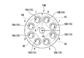
図7に示すように、この第二実施形態における燃料噴出器14Bは、上述した第一実施形態の燃料噴出器14Aと同様に、複数のメインバーナー16として第一バーナー16Aと、第二バーナー16Bと、を備えている。これら第一バーナー16Aと第二バーナー16Bとは、旋回方向が互いに逆方向である点を除いて、同一の構成となっている。
この第二実施形態における燃料噴出器14Bの第一バーナー16Aは、周方向に6つ連続して配置されている。燃料噴出器14Bの第二バーナー16Bは、周方向に2つ連続して配置されている。図7に示す燃料噴出器14Bは、図4と同様に、8つのメインバーナー16を備える場合を示しているが、メインバーナー16の数は、複数であればよく、例えば、9つ以上や、7つ以下であっても良い。
燃料噴出器14Bは、燃料噴出器14Aと同様に、周方向の全周に渡って非周期的な配置パターンで第一バーナー16Aと第二バーナー16Bとが配置されている。
燃料噴出器14Bは、さらに、第一バーナー16Aと第二バーナー16Bとが、燃焼器軸線Acを中心とした周方向で非対称な配置パターン(回転対称ではない配置パターン)で配置されている。
燃料噴出器14Bは、さらに、第一バーナー16Aと第二バーナー16Bとが、燃焼器軸線Acを中心とした周方向で非対称な配置パターン(回転対称ではない配置パターン)で配置されている。
燃料噴出器14Bは、第一実施形態の燃料噴出器14Aと同様に、その発熱率の重心位置gが、燃焼器軸線Acからオフセットしている。
第一実施形態の燃料噴出器14Aと同様に、周方向における第一バーナー16Aと第二バーナー16Bとの境界に生じる径方向の流れの向きに応じた単位ベクトルUA,UBをそれぞれ合成した合成ベクトルSVの大きさが単位ベクトルUA(又はUB)の大きさ以上となる配置パターンで、燃料噴出器14Bのメインバーナー16(第一バーナー16A、第二バーナー16B)が配置されている。
第一実施形態の燃料噴出器14Aと同様に、周方向における第一バーナー16Aと第二バーナー16Bとの境界に生じる径方向の流れの向きに応じた単位ベクトルUA,UBをそれぞれ合成した合成ベクトルSVの大きさが単位ベクトルUA(又はUB)の大きさ以上となる配置パターンで、燃料噴出器14Bのメインバーナー16(第一バーナー16A、第二バーナー16B)が配置されている。
燃料噴出器14Bは、周方向に隣接する2つのメインバーナー16を一つの群とすると、周方向に4つの群が設定できる。この場合、周方向のうち一方向(例えば、右回り)で見ると、2つの第二バーナー16Bからなる第一群G1と、二つの第一バーナー16Aからなる第二群G2から第四群G4と、が設定できる。第一群G1は、第二群G2から第四群G4の何れに対しても周方向の第一バーナー16Aと第二バーナー16Bとの配置順が異なっている。この第二実施形態の燃料噴出器14Bも、第一実施形態と同様に、8つのメインバーナー16を有している。つまり、複数のメインバーナー16を周方向に等分できる個数は、2個又は4個である。
上述した第二実施形態によれば、第一実施形態と同様に、第一バーナー16Aと第二バーナー16Bとが、燃焼器軸線Acを中心とする周方向の全周に渡って非周期的な配置パターンで配置されている。
これにより、燃料噴出器14Bは、外形が異なる複数種のメインバーナーを用いずに、周方向で一様ではない火炎を形成することができる。
その結果、メインバーナー16の製造に係る工数が増加することを抑制しつつ、燃焼振動の発生を抑制することができる。
これにより、燃料噴出器14Bは、外形が異なる複数種のメインバーナーを用いずに、周方向で一様ではない火炎を形成することができる。
その結果、メインバーナー16の製造に係る工数が増加することを抑制しつつ、燃焼振動の発生を抑制することができる。
また、第一バーナー16Aと第二バーナー16Bとを回転対称に配置しないため、火炎が、周方向で一様になることを抑制できる。
さらに、各メインバーナー16による火炎の発熱率を指標とした重心位置gが、複数のメインバーナー16の配置の中心位置である燃焼器軸線Acからオフセットしている。そのため、周方向における火炎のバランスを崩して、火炎が、周方向において一様になることを抑制できる。
また、第一バーナー16Aと第二バーナー16Bとの周方向における配置パターンが、合成ベクトルSVの大きさが単位ベクトルUA(又は、UB)の大きさ以上となる配置パターンである。そのため、周方向における火炎のバランスを崩して、火炎が、周方向において一様になることを抑制できる。
さらに、周方向に間隔をあけて配置された複数のメインバーナー16を、一または互いに周方向に隣接する複数のメインバーナー16からなり、且つ、同数のメインバーナー16からなる群に周方向に分割した場合に、少なくとも一つの群における第一バーナー16A及び第二バーナー16Bの配置関係が、他の群と異なるようにしている。そのため、火炎が、周方向において一様に形成されることを抑制できる。
(第三実施形態)
この発明の第三実施形態を図面に基づき説明する。この第三実施形態は、第二実施形態と同様に、上述した第一実施形態に対してメインバーナーの配置パターンを変化させたものである。そのため、上述した第一実施形態と同一部分に同一符号を付して説明するとともに、重複する説明を省略する。
この発明の第三実施形態を図面に基づき説明する。この第三実施形態は、第二実施形態と同様に、上述した第一実施形態に対してメインバーナーの配置パターンを変化させたものである。そのため、上述した第一実施形態と同一部分に同一符号を付して説明するとともに、重複する説明を省略する。
図8に示すように、第三実施形態における燃料噴出器14Cは、上述した第一実施形態の燃料噴出器14Aと同様に、複数のメインバーナー16として第一バーナー16Aと、第二バーナー16Bと、を備えている。これら第一バーナー16Aと第二バーナー16Bとは、旋回方向が互いに逆方向である点を除いて、同一の構成となっている。
第三実施形態における燃料噴出器14Cの第一バーナー16Aは、周方向に4つ連続して配置されている。この燃料噴出器14Cの第二バーナー16Bは、周方向に4つ連続して配置されている。図8に示す燃料噴出器14Cは、図4と同様に、8つのメインバーナー16を備える場合を示しているが、メインバーナー16の数は、複数であればよく、例えば、9つ以上や、7つ以下であっても良い。
燃料噴出器14Cの第一バーナー16Aと第二バーナー16Bとは、燃料噴出器14Aと同様に、周方向の全周に渡って非周期的な配置パターンで配置されている。
ここで、第三実施形態の第一バーナー16Aと第二バーナー16Bとの配置パターンは、一見すると周期的な配置パターンであるように見える。しかし、ここで言う周期的な配置パターンとは、周方向で第一バーナー16Aと第二バーナー16Bとが隣り合う配置パターンにおいて、例えば、周方向で第一バーナー16A、第二バーナー16Bの順、又は、第二バーナー16B、第一バーナー16Aの順の何れかの配置パターンが周方向に一周する間に2回以上現れる配置パターンを意味する。
ここで、第三実施形態の第一バーナー16Aと第二バーナー16Bとの配置パターンは、一見すると周期的な配置パターンであるように見える。しかし、ここで言う周期的な配置パターンとは、周方向で第一バーナー16Aと第二バーナー16Bとが隣り合う配置パターンにおいて、例えば、周方向で第一バーナー16A、第二バーナー16Bの順、又は、第二バーナー16B、第一バーナー16Aの順の何れかの配置パターンが周方向に一周する間に2回以上現れる配置パターンを意味する。
燃料噴出器14Bの第一バーナー16Aと第二バーナー16Bとは、燃焼器軸線Acを中心とした周方向で非対称な配置パターン(回転対称ではない配置パターン)で配置されている。
燃料噴出器14Bの発熱率の重心位置gは、第一実施形態の燃料噴出器14Aと同様に、燃焼器軸線Acからオフセットしている。
図示は省略するが、燃料噴出器14Cにおいて、周方向における第一バーナー16Aと第二バーナー16Bとの境界に生じる径方向の流れの向きに応じた単位ベクトルUA,UBをそれぞれ合成した合成ベクトルSVの大きさは、単位ベクトルUA(又は、UB)の大きさ以上となっている。つまり、燃料噴出器14Cのメインバーナー16(第一バーナー16A、第二バーナー16B)は、単位ベクトルUA(又はUB)の大きさ以上の合成ベクトルSVになる配置パターンで配置されている。なお、この第三実施形態における合成ベクトルSVの大きさは、単位ベクトルUA(又は、UB)に対して2倍の大きさとなっている。
燃料噴出器14Bの発熱率の重心位置gは、第一実施形態の燃料噴出器14Aと同様に、燃焼器軸線Acからオフセットしている。
図示は省略するが、燃料噴出器14Cにおいて、周方向における第一バーナー16Aと第二バーナー16Bとの境界に生じる径方向の流れの向きに応じた単位ベクトルUA,UBをそれぞれ合成した合成ベクトルSVの大きさは、単位ベクトルUA(又は、UB)の大きさ以上となっている。つまり、燃料噴出器14Cのメインバーナー16(第一バーナー16A、第二バーナー16B)は、単位ベクトルUA(又はUB)の大きさ以上の合成ベクトルSVになる配置パターンで配置されている。なお、この第三実施形態における合成ベクトルSVの大きさは、単位ベクトルUA(又は、UB)に対して2倍の大きさとなっている。
燃料噴出器14Bは、周方向に隣接する2つのメインバーナー16を一つの群とすると、周方向に4つの群が設定できる。この場合、周方向のうち一方向(例えば、右回り)で見ると、メインバーナー16の配置位置が「1」と「8」の1つの第一バーナー16Aと一つの第二バーナー16Bとからなる第一群G1と、二つの第一バーナー16Aからなる第二群G2と、一つの第二バーナー16Bと一つの第一バーナー16Aとからなる第三群G3と、二つの第一バーナー16Aからなる第四群G4と、が設定できる。第一群G1は、第二群G2から第四群G4の何れに対しても周方向の第一バーナー16Aと第二バーナー16Bとの配置順が異なっている。この第三実施形態の燃料噴出器14Cも、第一実施形態と同様に、8つのメインバーナー16を有している。つまり、複数のメインバーナー16を周方向に等分できる個数は、2個又は4個である。
上述した第三実施形態によれば、第一実施形態と同様に、燃焼器軸線Acを中心とする周方向の全周に渡って非周期的な配置パターンで第一バーナー16Aと第二バーナー16Bとが配置されている。
これにより、燃料噴出器14Cは、外形が異なる複数種のメインバーナーを用いずに、周方向で一様ではない火炎を形成することができる。
その結果、メインバーナー16の製造に係る工数が増加することを抑制しつつ、燃焼振動の発生を抑制することができる。
これにより、燃料噴出器14Cは、外形が異なる複数種のメインバーナーを用いずに、周方向で一様ではない火炎を形成することができる。
その結果、メインバーナー16の製造に係る工数が増加することを抑制しつつ、燃焼振動の発生を抑制することができる。
また、第一バーナー16Aと第二バーナー16Bとを回転対称に配置しないため、火炎が、周方向で一様になることを抑制できる。
さらに、各メインバーナー16による火炎の発熱率を指標とした重心位置gを、複数のメインバーナー16の配置の中心位置である燃焼器軸線Acからオフセットしているため、周方向における火炎のバランスを崩して、火炎が、一様になることを抑制できる。
また、第一バーナー16Aと第二バーナー16Bとの周方向における配置パターンを、合成ベクトルSVの大きさが単位ベクトルUA(又は、UB)の大きさ以上となる配置パターンとすることで、周方向における火炎のバランスを崩して、火炎が、一様になることを抑制できる。
さらに、周方向に間隔をあけて配置された複数のメインバーナー16を、一または互いに周方向に隣接する複数のメインバーナー16からなり、且つ、同数のメインバーナー16からなる群に周方向に分割した場合に、少なくとも一つの群における第一バーナー16A及び第二バーナー16Bの配置関係が、他の群と異なるようにしている。そのため、火炎が、周方向において一様に形成されることを抑制できる。
(第四実施形態)
次に、この発明の第四実施形態を図面に基づき説明する。この第四実施形態は、上述した第一実施形態に対してメインバーナーの配置パターンを変化させたものである。第四実施形態は、合成ベクトルの大きさが「1」未満になる点で第一実施形態と異なる。そのため、上述した第一実施形態と同一部分に同一符号を付して説明するとともに、重複する説明を省略する。
次に、この発明の第四実施形態を図面に基づき説明する。この第四実施形態は、上述した第一実施形態に対してメインバーナーの配置パターンを変化させたものである。第四実施形態は、合成ベクトルの大きさが「1」未満になる点で第一実施形態と異なる。そのため、上述した第一実施形態と同一部分に同一符号を付して説明するとともに、重複する説明を省略する。
図9に示すように、この第四実施形態における燃料噴出器14Dは、上述した第一実施形態の燃料噴出器14Aと同様に、複数のメインバーナー16として第一バーナー16Aと、第二バーナー16Bと、を備えている。これら第一バーナー16Aと第二バーナー16Bとは、旋回方向が互いに逆方向である点を除いて、同一の構成となっている。
この第四実施形態における燃料噴出器14Dは、7つの第一バーナー16Aが周方向に連続して配置されるとともに、1つの第二バーナー16Bが配置されている。つまり、周方向に配置された複数のメインバーナー16のうち、一つだけ第二バーナー16Bとされ、他の全てが第一バーナー16Aとなっている。図9に示す燃料噴出器14Dは、図4と同様に、8つのメインバーナー16を備える場合を示している。しかし、メインバーナー16の数は、複数であればよく、例えば、9つ以上や、7つ以下であっても良い。
燃料噴出器14Dの第一バーナー16Aと第二バーナー16Bとは、燃料噴出器14Aと同様に、周方向の全周に渡って非周期的な配置パターンで配置されている。
さらに、燃料噴出器14Dの第一バーナー16Aと第二バーナー16Bとは、燃焼器軸線Acを中心とした周方向で非対称な配置パターン(回転対称ではない配置パターン)で配置されている。
さらに、燃料噴出器14Dの第一バーナー16Aと第二バーナー16Bとは、燃焼器軸線Acを中心とした周方向で非対称な配置パターン(回転対称ではない配置パターン)で配置されている。
また、燃料噴出器14Dの発熱率の重心位置gは、第一実施形態の燃料噴出器1・BR>SAと同様に、燃焼器軸線Acからオフセットしている。
さらに、燃料噴出器14Dは、周方向に隣接する2つのメインバーナー16を一つの群とすると、周方向に4つの群が設定できる。この場合、周方向のうち一方向(例えば、右回り)で見ると、一つの第二バーナー16Bと一つの第一バーナー16Aとからなる第一群G1(メインバーナー16の配置番号「8」及び「7」)と、二つの第一バーナー16Aからなる第二群G2から第四群G4(メインバーナー16の配置番号「6」及び「5」,「4」及び「3」,「2」及び「1」)と、が設定できる。そして、第一群G1は、第二群G2から第四群G4の何れに対しても周方向における第一バーナー16Aと第二バーナー16Bとの配置順が異なっている。この第四実施形態の燃料噴出器14Dも、第一実施形態と同様に、8つのメインバーナー16を有している。つまり、複数のメインバーナー16を周方向に等分できる個数は、2個又は4個である。
上述した第四実施形態によれば、第一実施形態と同様に、燃焼器軸線Acを中心とする周方向の全周に渡って非周期的な配置パターンで第一バーナー16Aと第二バーナー16Bとが配置されている。
これにより、燃料噴出器14Dは、外形が異なる複数種のメインバーナーを用いずに、周方向で一様ではない火炎を形成することができる。
その結果、メインバーナー16の製造に係る工数が増加することを抑制しつつ、燃焼振動の発生を抑制することができる。
これにより、燃料噴出器14Dは、外形が異なる複数種のメインバーナーを用いずに、周方向で一様ではない火炎を形成することができる。
その結果、メインバーナー16の製造に係る工数が増加することを抑制しつつ、燃焼振動の発生を抑制することができる。
また、第一バーナー16Aと第二バーナー16Bとを回転対称に配置しないため、火炎が、周方向で一様になることを抑制できる。
さらに、各メインバーナー16による火炎の発熱率を指標とした重心位置gが、複数のメインバーナー16の配置の中心位置である燃焼器軸線Acからオフセットしている。そのため、周方向における火炎のバランスを崩して、火炎が、一様になることを抑制できる。
さらに、周方向に間隔をあけて配置された複数のメインバーナー16を、一または互いに周方向に隣接する複数のメインバーナー16からなり、且つ、同数のメインバーナー16からなる群に周方向に分割した場合に、少なくとも一つの群における第一バーナー16A及び第二バーナー16Bの配置関係が、他の群と異なるようにしている。そのため、火炎が、周方向において一様に形成されることを抑制できる。
次に、上述した各実施形態の燃料噴出器を有する燃焼器の実施例について説明する。
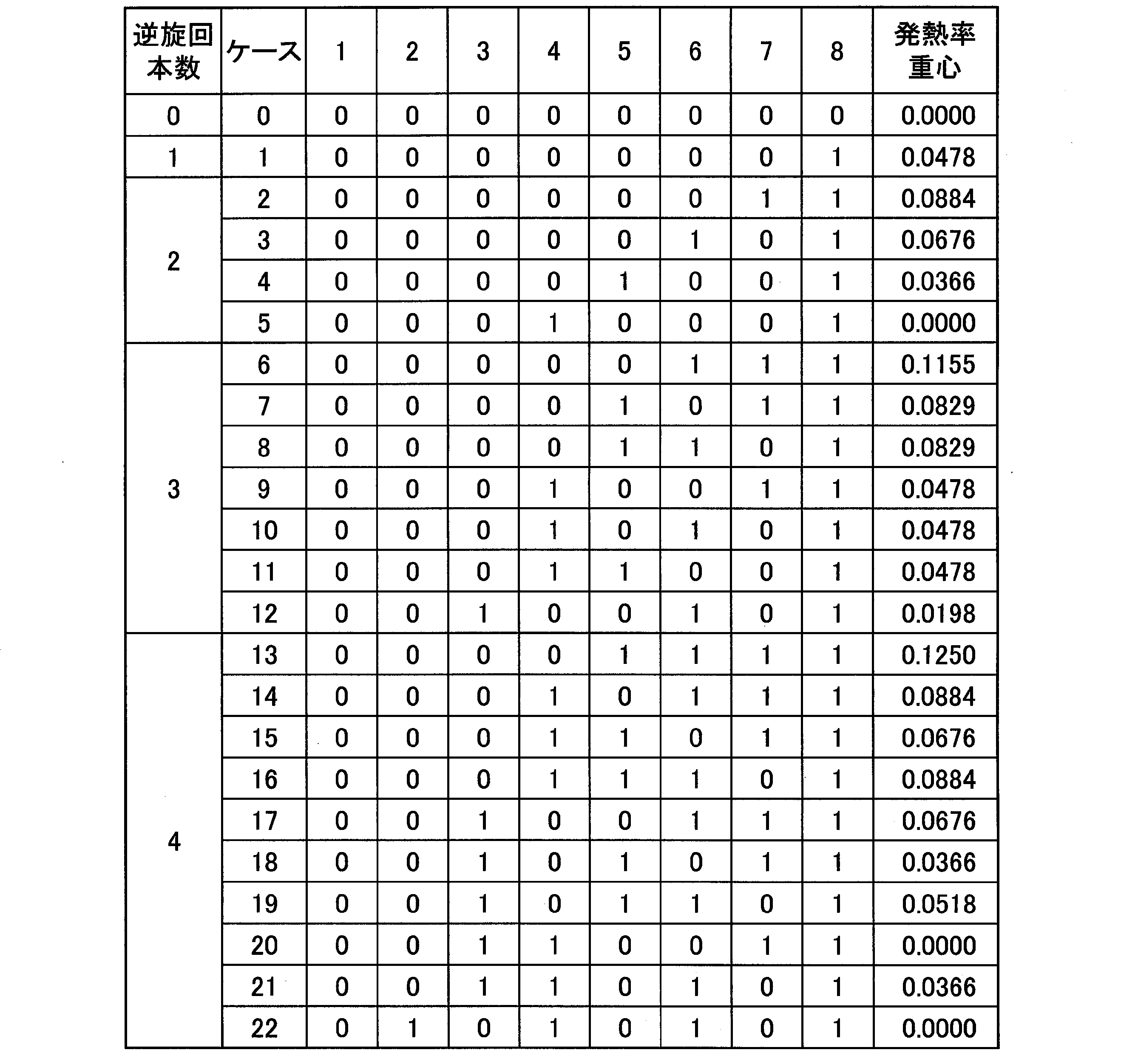
以下の表に示すケース1からケース22まで、第一バーナー16A及び第二バーナー16Bが配置される配置パターンについて、それぞれ発熱率の重心(発熱率重心)と、合成ベクトルの大きさとを求めるとともに、燃焼振動の大きさを求めた。以下の表において、各列における最も上に記載した「1」から「8」の数字は、上述した各実施形態の周方向におけるメインバーナー16の位置に対応している。以下の表において最も左側に記載された「逆旋回本数」とは、一つの燃料噴出器における第二バーナー16Bの本数である。また、「発熱率重心」は、燃焼器軸線Acから発熱率重心までの距離を示したものある。発熱率重心を計算する際、径方向外側に向かうスワールが強い場合は、発熱率を1.5とし、径方向内側に向かうスワールが強い場合は、発熱率を0.5としている。
以下の表に示すケース1からケース22まで、第一バーナー16A及び第二バーナー16Bが配置される配置パターンについて、それぞれ発熱率の重心(発熱率重心)と、合成ベクトルの大きさとを求めるとともに、燃焼振動の大きさを求めた。以下の表において、各列における最も上に記載した「1」から「8」の数字は、上述した各実施形態の周方向におけるメインバーナー16の位置に対応している。以下の表において最も左側に記載された「逆旋回本数」とは、一つの燃料噴出器における第二バーナー16Bの本数である。また、「発熱率重心」は、燃焼器軸線Acから発熱率重心までの距離を示したものある。発熱率重心を計算する際、径方向外側に向かうスワールが強い場合は、発熱率を1.5とし、径方向内側に向かうスワールが強い場合は、発熱率を0.5としている。
(実施例)
この表において、上述した第一実施形態の燃料噴出器14Aにおけるメインバーナー16の配置は、ケース「6」である。第二実施形態の燃料噴出器14Bにおけるメインバーナー16の配置は、ケース「2」である。第三実施形態の燃料噴出器14Cにおけるメインバーナー16の配置は、ケース「13」である。第四実施形態の燃料噴出器14Dにおけるメインバーナー16の配置は、ケース「1」である。
この表において、第一バーナー16Aが配置されている場合は「0」で示し、第二バーナー16Bが配置されている場合は「1」で示している。
この表において、上述した第一実施形態の燃料噴出器14Aにおけるメインバーナー16の配置は、ケース「6」である。第二実施形態の燃料噴出器14Bにおけるメインバーナー16の配置は、ケース「2」である。第三実施形態の燃料噴出器14Cにおけるメインバーナー16の配置は、ケース「13」である。第四実施形態の燃料噴出器14Dにおけるメインバーナー16の配置は、ケース「1」である。
この表において、第一バーナー16Aが配置されている場合は「0」で示し、第二バーナー16Bが配置されている場合は「1」で示している。
(比較例)
上記の表におけるケース「0」、ケース「5」、ケース「20」、ケース「22」は、それぞれ周方向の全周に渡って周期的な配置パターンで第一バーナー16Aと第二バーナー16Bとが配置されている。
上記の表におけるケース「0」、ケース「5」、ケース「20」、ケース「22」は、それぞれ周方向の全周に渡って周期的な配置パターンで第一バーナー16Aと第二バーナー16Bとが配置されている。
(発熱率重心)
比較例であるケース「0」、ケース「5」、ケース「20」、ケース「22」の発熱率重心の値は、何れも「0.0000」となった。
その一方で、比較例を除く全てのケースについては、発熱率重心の値が「0.0000」よりも大きくなっている。
比較例であるケース「0」、ケース「5」、ケース「20」、ケース「22」の発熱率重心の値は、何れも「0.0000」となった。
その一方で、比較例を除く全てのケースについては、発熱率重心の値が「0.0000」よりも大きくなっている。
(合成ベクトルの大きさ)
図10において、実線は、発熱率重心の値を示している。図10において、破線は、合成ベクトルの大きさを示している。図10において、横軸の左端部がケース「0」であり、右端部がケース「22」である。つまり、横軸においてケース番号は、右側に向かうほど大きくなっている。図10中、水平方向に延びる太い実線は、これら発熱率重心の値と合成ベクトルの大きさとの基準値の一例である。
図10において、実線は、発熱率重心の値を示している。図10において、破線は、合成ベクトルの大きさを示している。図10において、横軸の左端部がケース「0」であり、右端部がケース「22」である。つまり、横軸においてケース番号は、右側に向かうほど大きくなっている。図10中、水平方向に延びる太い実線は、これら発熱率重心の値と合成ベクトルの大きさとの基準値の一例である。
図10に示すように、合成ベクトルの大きさ(破線)は、発熱率重心の値(実線)と相関があることが分かる。これら合成ベクトルの大きさと発熱率重心の値とは、上述した第一、第二、第三実施形態に対応するケース「2」、「6」、「13」において、特に高い数値となっている。これらケース「2」、「6」、「13」よりも低い数値ではあるものの、第四実施形態に対応するケース「1」の場合も、合成ベクトルの大きさ、及び発熱率重心の値は、「0」よりも十分に高い値となっている。
燃焼振動による圧力変動の値をシミュレーション計算により検証したところ、ケース「1」、「2」、「6」、「13」において、それぞれケース「0」よりも燃焼振動が低減される傾向が確認された。
これらケース「1」、「2」、「6」、「13」は、何れも、第一バーナー16Aと第二バーナー16Bとの配置が非周期的であるとともに回転対称ではなく、さらにそれぞれの発熱率重心の値と合成ベクトルの大きさとが、ケース「0」の場合よりも大きくなっている。特に、ケース「2」、「6」において、燃焼振動の低減が顕著となった。
つまり、第一バーナー16Aと第二バーナー16Bとの配置パターンの非周期性と、燃焼振動の低減との間に相関があることが確認された。
これらケース「1」、「2」、「6」、「13」は、何れも、第一バーナー16Aと第二バーナー16Bとの配置が非周期的であるとともに回転対称ではなく、さらにそれぞれの発熱率重心の値と合成ベクトルの大きさとが、ケース「0」の場合よりも大きくなっている。特に、ケース「2」、「6」において、燃焼振動の低減が顕著となった。
つまり、第一バーナー16Aと第二バーナー16Bとの配置パターンの非周期性と、燃焼振動の低減との間に相関があることが確認された。
この発明は上述した各実施形態の構成に限られるものではなく、その要旨を逸脱しない範囲で設計変更可能である。
例えば、第一実施形態から第四実施形態の配置パターンに限られない。すなわち、ケース「1」、「2」、「6」、「13」の配置パターンに限られない。ケース「0」、ケース「5」、ケース「20」、ケース「22」を除く他のケース(配置パターン)であれば、ケース「1」、「2」、「6」、「13」以外の配置パターンであっても良い。
例えば、第一実施形態から第四実施形態の配置パターンに限られない。すなわち、ケース「1」、「2」、「6」、「13」の配置パターンに限られない。ケース「0」、ケース「5」、ケース「20」、ケース「22」を除く他のケース(配置パターン)であれば、ケース「1」、「2」、「6」、「13」以外の配置パターンであっても良い。
この発明は、燃焼器及びガスタービンに適用できる。この発明によれば、メインバーナーの製造に係る工数が増加することを抑制しつつ、燃焼振動の発生を抑制することができる。
1 ガスタービン
2 圧縮機
3 燃焼器
4 燃焼ガスをタービン
4 タービン
6 圧縮機ロータ
7 圧縮機ケーシング
8 タービンロータ
9 タービンケーシング
10 ガスタービンロータ
11 ガスタービンケーシング
13 燃焼筒
14A,14B,14C,14D 燃料噴出器
15 パイロットバーナー
16 メインバーナー
16A 第一バーナー
16B 第二バーナー
17 バーナー保持筒
18 パイロットノズル
18a 燃料噴射用の噴射孔
19 パイロットバーナー筒
21 本体部
22 コーン部
23 メインノズル
23a 燃料噴射用の噴射孔
24 メインバーナー筒
25 メインスワラ
A 圧縮空気(一次空気)
Ac 燃焼器軸線
Ar 回転軸線
Da 軸線方向
F 燃料
g 重心位置
G1 第一群
G2 第二群
G3 第三群
G4 第四群
GEN 発電機
SV 合成ベクトル
UA 単位ベクトル
UB 単位ベクトル
2 圧縮機
3 燃焼器
4 燃焼ガスをタービン
4 タービン
6 圧縮機ロータ
7 圧縮機ケーシング
8 タービンロータ
9 タービンケーシング
10 ガスタービンロータ
11 ガスタービンケーシング
13 燃焼筒
14A,14B,14C,14D 燃料噴出器
15 パイロットバーナー
16 メインバーナー
16A 第一バーナー
16B 第二バーナー
17 バーナー保持筒
18 パイロットノズル
18a 燃料噴射用の噴射孔
19 パイロットバーナー筒
21 本体部
22 コーン部
23 メインノズル
23a 燃料噴射用の噴射孔
24 メインバーナー筒
25 メインスワラ
A 圧縮空気(一次空気)
Ac 燃焼器軸線
Ar 回転軸線
Da 軸線方向
F 燃料
g 重心位置
G1 第一群
G2 第二群
G3 第三群
G4 第四群
GEN 発電機
SV 合成ベクトル
UA 単位ベクトル
UB 単位ベクトル
Claims (6)
- 一次空気を旋回させて混合気を生成するメインバーナーとしての第一バーナーと、
前記第一バーナーとは逆方向に一次空気を旋回させて混合気を生成するメインバーナーとしての第二バーナーと、を備え、
前記メインバーナーは、周方向に間隔をあけて複数配置され、
前記周方向の全周に渡って非周期的な配置パターンで前記第一バーナーと前記第二バーナーとが配置されている燃焼器。 - 前記第一バーナーと、前記第二バーナーとは、
周方向で非対称な配置パターンで配置されている請求項1に記載の燃焼器。 - 前記第一バーナーと、前記第二バーナーとは、
複数の前記メインバーナーの全体の発熱率の重心位置が、前記周方向の中心位置からオフセットする配置パターンで配置されている請求項1に記載の燃焼器。 - 前記第一バーナーと、前記第二バーナーとは、
周方向における前記第一バーナーと前記第二バーナーとの境界に生じる径方向の流れの向きに応じた単位ベクトルをそれぞれ合成した合成ベクトルの大きさが前記単位ベクトルの大きさ以上となる配置パターンで配置されている請求項1に記載の燃焼器。 - 周方向に間隔をあけて配置された複数の前記メインバーナーを、一または互いに周方向に隣接する複数のメインバーナーからなり、且つ、同数のメインバーナーからなる群に周方向に分割した場合に、
少なくとも一つの前記群における第一バーナー及び第二バーナーの配置関係が、他の前記群と異なる請求項1に記載の燃焼器。 - 請求項1から5の何れか一項に記載の燃焼器を備えるガスタービン。
Priority Applications (3)
| Application Number | Priority Date | Filing Date | Title |
|---|---|---|---|
| CN201880012407.2A CN110300872B (zh) | 2017-02-21 | 2018-02-21 | 燃烧器及燃气轮机 |
| DE112018000929.7T DE112018000929T5 (de) | 2017-02-21 | 2018-02-21 | Brennkammer und gasturbine |
| US16/486,604 US20200056788A1 (en) | 2017-02-21 | 2018-02-21 | Combustor and gas turbine |
Applications Claiming Priority (2)
| Application Number | Priority Date | Filing Date | Title |
|---|---|---|---|
| JP2017029640A JP6822868B2 (ja) | 2017-02-21 | 2017-02-21 | 燃焼器及びガスタービン |
| JP2017-029640 | 2017-12-29 |
Publications (1)
| Publication Number | Publication Date |
|---|---|
| WO2018155496A1 true WO2018155496A1 (ja) | 2018-08-30 |
Family
ID=63254413
Family Applications (1)
| Application Number | Title | Priority Date | Filing Date |
|---|---|---|---|
| PCT/JP2018/006243 Ceased WO2018155496A1 (ja) | 2017-02-21 | 2018-02-21 | 燃焼器及びガスタービン |
Country Status (5)
| Country | Link |
|---|---|
| US (1) | US20200056788A1 (ja) |
| JP (1) | JP6822868B2 (ja) |
| CN (1) | CN110300872B (ja) |
| DE (1) | DE112018000929T5 (ja) |
| WO (1) | WO2018155496A1 (ja) |
Cited By (1)
| Publication number | Priority date | Publication date | Assignee | Title |
|---|---|---|---|---|
| CN112944396A (zh) * | 2021-05-13 | 2021-06-11 | 中国人民解放军国防科技大学 | 一种壁面喷注气态燃料与超声速来流混合效率的测量方法 |
Families Citing this family (1)
| Publication number | Priority date | Publication date | Assignee | Title |
|---|---|---|---|---|
| JP7646441B2 (ja) | 2021-04-30 | 2025-03-17 | 東芝エネルギーシステムズ株式会社 | ガスタービン燃焼器構造体 |
Citations (2)
| Publication number | Priority date | Publication date | Assignee | Title |
|---|---|---|---|---|
| US1508718A (en) * | 1922-03-09 | 1924-09-16 | Ernest H Peabody | Apparatus for burning liquid fuel |
| JP2006258041A (ja) * | 2005-03-18 | 2006-09-28 | Kawasaki Heavy Ind Ltd | ガスタービン燃焼器およびその着火方法 |
Family Cites Families (8)
| Publication number | Priority date | Publication date | Assignee | Title |
|---|---|---|---|---|
| US3872664A (en) * | 1973-10-15 | 1975-03-25 | United Aircraft Corp | Swirl combustor with vortex burning and mixing |
| JPS5124937A (ja) * | 1974-08-27 | 1976-02-28 | Mitsubishi Heavy Ind Ltd | Nenryonenshosochi |
| GB2319078B (en) * | 1996-11-08 | 1999-11-03 | Europ Gas Turbines Ltd | Combustor arrangement |
| US8511097B2 (en) * | 2005-03-18 | 2013-08-20 | Kawasaki Jukogyo Kabushiki Kaisha | Gas turbine combustor and ignition method of igniting fuel mixture in the same |
| US20100192578A1 (en) * | 2009-01-30 | 2010-08-05 | General Electric Company | System and method for suppressing combustion instability in a turbomachine |
| US8763399B2 (en) * | 2009-04-03 | 2014-07-01 | Hitachi, Ltd. | Combustor having modified spacing of air blowholes in an air blowhole plate |
| EP2796789B1 (en) * | 2013-04-26 | 2017-03-01 | General Electric Technology GmbH | Can combustor for a can-annular combustor arrangement in a gas turbine |
| JP2015083779A (ja) * | 2013-10-25 | 2015-04-30 | 三菱日立パワーシステムズ株式会社 | ガスタービン燃焼器及びガスタービン燃焼器の制御方法 |
-
2017
- 2017-02-21 JP JP2017029640A patent/JP6822868B2/ja not_active Expired - Fee Related
-
2018
- 2018-02-21 DE DE112018000929.7T patent/DE112018000929T5/de not_active Withdrawn
- 2018-02-21 WO PCT/JP2018/006243 patent/WO2018155496A1/ja not_active Ceased
- 2018-02-21 CN CN201880012407.2A patent/CN110300872B/zh not_active Expired - Fee Related
- 2018-02-21 US US16/486,604 patent/US20200056788A1/en not_active Abandoned
Patent Citations (2)
| Publication number | Priority date | Publication date | Assignee | Title |
|---|---|---|---|---|
| US1508718A (en) * | 1922-03-09 | 1924-09-16 | Ernest H Peabody | Apparatus for burning liquid fuel |
| JP2006258041A (ja) * | 2005-03-18 | 2006-09-28 | Kawasaki Heavy Ind Ltd | ガスタービン燃焼器およびその着火方法 |
Cited By (2)
| Publication number | Priority date | Publication date | Assignee | Title |
|---|---|---|---|---|
| CN112944396A (zh) * | 2021-05-13 | 2021-06-11 | 中国人民解放军国防科技大学 | 一种壁面喷注气态燃料与超声速来流混合效率的测量方法 |
| CN112944396B (zh) * | 2021-05-13 | 2021-07-09 | 中国人民解放军国防科技大学 | 一种壁面喷注气态燃料与超声速来流混合效率的测量方法 |
Also Published As
| Publication number | Publication date |
|---|---|
| CN110300872B (zh) | 2021-09-14 |
| DE112018000929T5 (de) | 2019-10-31 |
| JP6822868B2 (ja) | 2021-01-27 |
| US20200056788A1 (en) | 2020-02-20 |
| CN110300872A (zh) | 2019-10-01 |
| JP2018136056A (ja) | 2018-08-30 |
Similar Documents
| Publication | Publication Date | Title |
|---|---|---|
| JP4177812B2 (ja) | タービンエンジンの燃料ノズル | |
| JP5524407B2 (ja) | ガスタービン燃焼器およびガスタービン | |
| JP5802059B2 (ja) | 燃料噴射ノズル本体上の火炎安定化用のディンプル付き/グルーブ付き面及び関連する方法 | |
| EP0952392B1 (en) | Combustor | |
| US10125992B2 (en) | Gas turbine combustor with annular flow sleeves for dividing airflow upstream of premixing passages | |
| JP2010223577A (ja) | スワーラ、少なくとも1つのスワーラを備えたバーナにおける逆火の防止方法およびバーナ | |
| JP2010223577A6 (ja) | スワーラ、少なくとも1つのスワーラを備えたバーナにおける逆火の防止方法およびバーナ | |
| US9194587B2 (en) | Gas turbine combustion chamber | |
| WO2014148166A1 (ja) | 燃焼器、および、ガスタービン | |
| CN115711176B (zh) | 具有集成喇叭形旋流器的圆顶 | |
| WO2013128572A1 (ja) | 燃焼器及びガスタービン | |
| JP2017227430A (ja) | 予混合パイロットノズルおよび燃料ノズルアセンブリ | |
| JP7257358B2 (ja) | ガスタービン燃焼器 | |
| CN105318357A (zh) | 用于燃气涡轮发动机燃烧器导流罩的圆锥-平坦隔热罩 | |
| WO2017154821A1 (ja) | バーナアセンブリ、燃焼器、及びガスタービン | |
| JP7161567B2 (ja) | 燃焼器及びガスタービン | |
| WO2018155496A1 (ja) | 燃焼器及びガスタービン | |
| JP7126346B2 (ja) | バーナ装置 | |
| JP2017180906A (ja) | ガスタービン燃焼器 | |
| JP2014178107A (ja) | NOx排出物質を制限するための拡散型燃焼器燃料ノズル | |
| JP6239943B2 (ja) | ガスタービン燃焼器 | |
| JP6692847B2 (ja) | ガスタービン燃焼器及びこれを備えたガスタービン機関 | |
| CN102692036A (zh) | 具有带有人字形肋的燃料喷嘴衬套的燃烧器 | |
| JP2017155955A (ja) | 燃焼器、ガスタービン | |
| JP5743122B2 (ja) | 燃焼器及びガスタービン |
Legal Events
| Date | Code | Title | Description |
|---|---|---|---|
| 121 | Ep: the epo has been informed by wipo that ep was designated in this application |
Ref document number: 18758318 Country of ref document: EP Kind code of ref document: A1 |
|
| 122 | Ep: pct application non-entry in european phase |
Ref document number: 18758318 Country of ref document: EP Kind code of ref document: A1 |