WO2018155320A1 - Conical roller bearing - Google Patents
Conical roller bearing Download PDFInfo
- Publication number
- WO2018155320A1 WO2018155320A1 PCT/JP2018/005397 JP2018005397W WO2018155320A1 WO 2018155320 A1 WO2018155320 A1 WO 2018155320A1 JP 2018005397 W JP2018005397 W JP 2018005397W WO 2018155320 A1 WO2018155320 A1 WO 2018155320A1
- Authority
- WO
- WIPO (PCT)
- Prior art keywords
- roughness
- tapered roller
- roller bearing
- roughness curve
- rku
- Prior art date
Links
Images


Classifications
-
- F—MECHANICAL ENGINEERING; LIGHTING; HEATING; WEAPONS; BLASTING
- F16—ENGINEERING ELEMENTS AND UNITS; GENERAL MEASURES FOR PRODUCING AND MAINTAINING EFFECTIVE FUNCTIONING OF MACHINES OR INSTALLATIONS; THERMAL INSULATION IN GENERAL
- F16C—SHAFTS; FLEXIBLE SHAFTS; ELEMENTS OR CRANKSHAFT MECHANISMS; ROTARY BODIES OTHER THAN GEARING ELEMENTS; BEARINGS
- F16C19/00—Bearings with rolling contact, for exclusively rotary movement
- F16C19/22—Bearings with rolling contact, for exclusively rotary movement with bearing rollers essentially of the same size in one or more circular rows, e.g. needle bearings
- F16C19/34—Bearings with rolling contact, for exclusively rotary movement with bearing rollers essentially of the same size in one or more circular rows, e.g. needle bearings for both radial and axial load
- F16C19/36—Bearings with rolling contact, for exclusively rotary movement with bearing rollers essentially of the same size in one or more circular rows, e.g. needle bearings for both radial and axial load with a single row of rollers
- F16C19/364—Bearings with rolling contact, for exclusively rotary movement with bearing rollers essentially of the same size in one or more circular rows, e.g. needle bearings for both radial and axial load with a single row of rollers with tapered rollers, i.e. rollers having essentially the shape of a truncated cone
-
- F—MECHANICAL ENGINEERING; LIGHTING; HEATING; WEAPONS; BLASTING
- F16—ENGINEERING ELEMENTS AND UNITS; GENERAL MEASURES FOR PRODUCING AND MAINTAINING EFFECTIVE FUNCTIONING OF MACHINES OR INSTALLATIONS; THERMAL INSULATION IN GENERAL
- F16C—SHAFTS; FLEXIBLE SHAFTS; ELEMENTS OR CRANKSHAFT MECHANISMS; ROTARY BODIES OTHER THAN GEARING ELEMENTS; BEARINGS
- F16C33/00—Parts of bearings; Special methods for making bearings or parts thereof
- F16C33/30—Parts of ball or roller bearings
- F16C33/34—Rollers; Needles
- F16C33/36—Rollers; Needles with bearing-surfaces other than cylindrical, e.g. tapered; with grooves in the bearing surfaces
- F16C33/366—Tapered rollers, i.e. rollers generally shaped as truncated cones
-
- F—MECHANICAL ENGINEERING; LIGHTING; HEATING; WEAPONS; BLASTING
- F16—ENGINEERING ELEMENTS AND UNITS; GENERAL MEASURES FOR PRODUCING AND MAINTAINING EFFECTIVE FUNCTIONING OF MACHINES OR INSTALLATIONS; THERMAL INSULATION IN GENERAL
- F16C—SHAFTS; FLEXIBLE SHAFTS; ELEMENTS OR CRANKSHAFT MECHANISMS; ROTARY BODIES OTHER THAN GEARING ELEMENTS; BEARINGS
- F16C33/00—Parts of bearings; Special methods for making bearings or parts thereof
- F16C33/30—Parts of ball or roller bearings
- F16C33/58—Raceways; Race rings
- F16C33/583—Details of specific parts of races
- F16C33/585—Details of specific parts of races of raceways, e.g. ribs to guide the rollers
-
- F—MECHANICAL ENGINEERING; LIGHTING; HEATING; WEAPONS; BLASTING
- F16—ENGINEERING ELEMENTS AND UNITS; GENERAL MEASURES FOR PRODUCING AND MAINTAINING EFFECTIVE FUNCTIONING OF MACHINES OR INSTALLATIONS; THERMAL INSULATION IN GENERAL
- F16C—SHAFTS; FLEXIBLE SHAFTS; ELEMENTS OR CRANKSHAFT MECHANISMS; ROTARY BODIES OTHER THAN GEARING ELEMENTS; BEARINGS
- F16C2240/00—Specified values or numerical ranges of parameters; Relations between them
- F16C2240/40—Linear dimensions, e.g. length, radius, thickness, gap
- F16C2240/54—Surface roughness
Definitions
- This invention relates to a tapered roller bearing.
- the roller large end surface of the tapered roller and the large collar surface of the inner ring make sliding contact.
- a preload is applied for the purpose of improving the rigidity and rotational accuracy of the tapered roller bearing.
- the rotational torque is measured in a state where it is rotated at a low speed (usually 100 r / min or less) for the convenience of the incorporation process into the counterpart device.
- the tapered roller bearing disclosed in Patent Document 1 below has a surface roughness Ra of 0.05 mm to maintain a proper lubrication state between the large collar surface of the inner ring and the large roller end surface of the tapered roller. It is formed in a range of ⁇ 0.20 ⁇ m.
- the lubrication state between the large collar surface of the inner ring and the roller large end surface of the tapered roller during mixed-in operation is a mixed lubrication of fluid lubrication and boundary lubrication.
- the friction coefficient fluctuates greatly, the variation in the measured rotational torque increases, and the preload management accuracy deteriorates.
- the surface roughness Ra of the large collar surface is 0.05 ⁇ m or more, the lubrication state becomes boundary lubrication, the friction coefficient is stabilized, and the preload can be managed with high accuracy.
- the tapered roller bearing disclosed in Patent Document 2 below has a tapered roller having a roller large end surface with a surface roughness Ra of 0.1 ⁇ m or less, and an inner ring having a large flange surface with a surface roughness Ra of 0.2 ⁇ m.
- JP 2000-170774 A (particularly paragraphs 0021 to 0023 of the specification)
- JP 2002-139055 A (particularly paragraph 0021 of the specification)
- the tapered roller bearings of Patent Documents 1 and 2 define the range of the surface roughness Ra of the large collar surface of the inner ring in order to stabilize the rotational torque during low-speed rotation when preload is set.
- the bearing also includes a super-finished roughness range (for example, Ra is 0.08 ⁇ m or less). At super-finished roughness, the rotational torque may become unstable.
- the surface roughness Ra of the large collar surface of the inner ring is made rougher than the roughness range of the superfinishing level, it is considered that the rotational torque during low-speed rotation can be stabilized.
- the seizure resistance is inferior to the range.
- the problem to be solved by the present invention is to achieve both the stability of rotational torque during low-speed rotation and the seizure resistance between the large flange surface and the large end surface in a tapered roller bearing. .
- the present invention provides a tapered roller bearing comprising a tapered roller having a roller large end surface and an inner ring having a large collar surface in sliding contact with the roller large end surface, the arithmetic average of the large collar surface
- the roughness Ra is 0.1 ⁇ m ⁇ Ra ⁇ 0.2 ⁇ m
- the skewness Rsk of the roughness surface of the large ridge surface is ⁇ 1.0 ⁇ Rsk ⁇ ⁇ 0.3
- the roughness curve of the large ridge surface is The configuration of the kurtosis Rku of 3.0 ⁇ Rku ⁇ 5.0 was adopted.
- the arithmetic average roughness Ra in the present invention refers to the arithmetic average roughness Ra defined by Japanese Industrial Standard (JIS) B0601: 2013.
- the skewness Rsk of the roughness curve in the present invention refers to the skewness Rsk of the roughness curve defined by Japanese Industrial Standard (JIS) B0601: 2013.
- the kurtosis Rku of the roughness curve in the present invention refers to the kurtosis Rku of the roughness curve defined by Japanese Industrial Standard (JIS) B0601: 2013.
- the tapered roller bearing is rotated at a low speed: in the range of 0 to 200 (r / min).
- This is a characteristic suitable for stabilizing the rotational torque at.
- This alone will cause the seizure resistance to be inferior to the roughness of the superfinishing level, and therefore the present invention further defines the surface texture characteristics of the roughness curve of the large surface. That is, when the skewness Rsk ⁇ 0 of the roughness curve, the characteristic is biased to the upper side with respect to the average line. Therefore, by setting the Rsk of the large surface to a negative numerical range, the large surface has a flat surface.
- the skewness Rsk of the roughness curve of the large ridge surface is set to -1.0 to -0.3. Further, when the kurtosis Rku of the roughness curve is smaller than 3, the shape of the surface unevenness distribution is crushed, but a roughness protrusion is also required to stabilize the rotational torque. Therefore, the kurtosis Rku of the roughness curve of the large ridge surface is set to 3.0 to 5.0. If the characteristic balance in the range of Ra, Rsk, and Rku described above is used, the stability of rotational torque during low-speed rotation and the seizure resistance between the large flange surface and the large end surface can be realized. Can do.
- the arithmetic average roughness Ra of the roller large end face may be 0.1 ⁇ m or less. Since the surface roughness of the roller large end face has less influence on the function than the surface roughness of the large collar surface of the inner ring, it is not necessary to further define the skewness Rsk and kurtosis Rku, and can be managed simply by the calculated average roughness Ra. Good.
- the large ridge surface may be a shape defined by a straight bus bar or a bus bar having a central recess or convexity of 1 ⁇ m or less.
- the roller large end face and the large collar surface can realize particularly good seizure resistance when the spherical surface and the flat surface are in a contact relationship.
- the bus bar shape of the large ridge surface is a substantially linear shape to the extent that it can be obtained with industrial products.
- the large corrugated surface has a generatrix shape that is concave or convex, if the amount of the concave or convex portion exceeds 1 ⁇ m, a good lubricating oil wedge effect cannot be obtained.
- the tapered roller bearing according to the present invention is suitable for those incorporated in a power transmission device of an automobile.
- An automobile power transmission device is an element that constitutes a path for transmitting power from a driving source of an automobile to wheels, and includes, for example, a differential, a transmission, and the like.
- Partial sectional view showing a tapered roller bearing according to an embodiment of the present invention Enlarged view of the area near the surface of Figure 1
- the fragmentary sectional view which shows another bus-bar shape of the large collar surface of FIG. Conceptual diagram illustrating the effect of the roughness curve skewness RSk on the surface properties
- Conceptual diagram illustrating the influence of the value of the kurtosis RKu of the roughness curve on the surface properties The graph which shows the relationship between the rotational speed and rotational torque of an Example and a comparative example
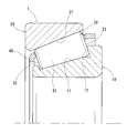
- the tapered roller bearing 1 includes an inner ring 10, an outer ring 20, a plurality of tapered rollers 30, and a cage 40 that holds these tapered rollers 30.
- the inner ring 10, the outer ring 20, and the tapered roller 30 are each made of steel.
- the inner ring 10 and the outer ring 20 are annular bearing parts arranged coaxially.
- the inner ring 10 has a track 11 and a large collar surface 12 on the outside.
- the outer ring 20 has a track 21 inside.
- the tracks 11 and 21 are each formed in a conical surface shape.
- the tapered roller 30 includes a tapered rolling surface 31, a small roller end surface 32, and a large roller end surface 33.
- the rolling surface 31 is interposed between the track 11 of the inner ring 10 and the track 21 of the outer ring 20.
- the roller small end surface 32 is a side surface on the small diameter side of the tapered roller 30.
- the roller large end surface 33 is a side surface on the large diameter side of the tapered roller 30.
- the roller large end face 33 has a spherical shape.
- the surface roughness of the roller large end surface 33 has less influence on functions such as seizure resistance than the roughness of the large collar surface 12 of the inner ring 10. For this reason, what is necessary is just to manage the surface roughness of the roller large end surface 33 by arithmetic mean roughness Ra simply.
- the arithmetic average roughness Ra of the roller large end face 33 may be 0.1 ⁇ m or less.
- the arithmetic average roughness Ra is the arithmetic average roughness Ra defined in 4.2.1 of Japanese Industrial Standard (JIS) B0601: 2013.
- the unit of arithmetic average roughness Ra is ⁇ m.
- the large collar surface 12 of the inner ring 10 is in sliding contact with the roller large end surface 33 of the tapered roller 30. That is, the large collar surface 12 is an inner ring surface portion that can come into sliding contact with the roller large end surface 33 during bearing rotation.
- the large collar surface 12 is formed in a shape (that is, a conical surface shape) defined by a straight generatrix.
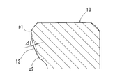
- the large ridge surface 12 may have a shape defined by a bus bar having a center recess of 1 ⁇ m or less, or may have a shape defined by a bus bar having a center projection of 1 ⁇ m or less as shown in FIG. 4. .
- the center concave is from p1 and p2 toward the center of the reference straight line. The shape gradually dented away from the roller large end face 33.
- middle convex means a shape that gradually bulges toward the center of the reference straight line from the aforementioned p1 and p2 toward the roller large end face 33.
- the phrase “middle concave or middle convex is within 1 ⁇ m” means that the maximum concave amount or bulging amount ⁇ l from the reference straight line is within 1 ⁇ m.
- the large collar surface 12 has a straight busbar (see FIG. 2), or a center recess (see FIG. 3) or a center convexity (see FIG. 4) defined by a bus within 1 ⁇ m, the large roller end face 33 and the large end surface 33 are large. Since the flange surface 12 has a contact relationship between the spherical surface and the flat surface or a contact relationship similar to this, a good wedge effect of the lubricating oil can be realized between the roller large end surface 33 and the large flange surface 12. .
- the arithmetic average roughness Ra of the large surface 12 is 0.1 ⁇ m ⁇ Ra ⁇ 0.2 ⁇ m.
- the large flange surface 12 is rotated at a low speed of the tapered roller bearing 1 shown in FIG. 1: 0 to 200 (r / min) In this range, the characteristics are suitable for stabilizing the rotational torque.
- the skewness Rsk of the roughness curve of the large surface 12 is ⁇ 1.0 ⁇ Rsk ⁇ ⁇ 0.3.
- the skewness Rsk of the roughness curve is the skewness Rsk of the roughness curve defined in 4.2.3 of Japanese Industrial Standard (JIS) B0601: 2013.
- the skewness Rsk of the roughness curve is defined by the following equation (1).
- the skewness Rsk of the roughness curve is the cube average of Z (x) at the reference length made dimensionless by the cube of the root mean square roughness Rq of the cross-sectional curve, as shown in Equation (1).
- the skewness Rsk of the roughness curve is a numerical value indicating the degree of asymmetry of the probability density function of the contour curve, and is a parameter that is strongly influenced by the protruding peaks or valleys.
- FIG. 5 illustrates a roughness curve satisfying the skewness Rsk> 0 and a roughness curve satisfying the skewness Rsk ⁇ 0.
- the kurtosis Rku of the roughness curve of the large ridge surface 12 is 3.0 ⁇ Rku ⁇ 5.0.
- the kurtosis Rku of the roughness curve refers to the kurtosis Rku of the roughness curve defined in Japanese Industrial Standards (JIS) B0601: 2013 4.2.4.
- the kurtosis Rku of the roughness curve is defined by the following equation (2).
- the kurtosis Rku of the roughness curve is the root mean square of Z (x) at the reference length made dimensionless by the square of the root mean square roughness Rq of the cross section curve, as shown in Equation (2).
- the kurtosis Rku of the roughness curve is a numerical value indicating the degree of sharpness (sharpness) of the probability density function of the contour curve, and is a parameter that is strongly influenced by protruding peaks or valleys.
- FIG. 6 illustrates a roughness curve satisfying Kurtosis Rku> 3 and a roughness curve satisfying Kurtosis Rku ⁇ 3.
- Arithmetic mean roughness Ra, roughness curve skewness Rsk, and roughness curve kurtosis Rku can all be measured by a surface roughness measuring machine.
- This tapered roller bearing 1 has an arithmetic average roughness Ra: 0.1 to 0.2 ⁇ m, a roughness curve skewness Rsk: ⁇ 1.0 to ⁇ 0.3, and a roughness curve kurtosis Rku: 3.0 to Since the large collar surface 12 having a characteristic balance in the range of 5.0 is adopted, both the stability of the rotational torque at the time of low speed rotation and the seizure resistance between the large collar surface 12 and the large end surface 33 are achieved. Can do.
- the seizure resistance is inferior to the case where the arithmetic average roughness Ra of the large collar surface 12 is less than 0.1 ⁇ m.
- the large flange surface 12 having the above-mentioned characteristic balance is ground, the roughness regulation range is too fine and the processing resistance is too large, which may cause grinding burn.
- Surface roughness Ra In order to achieve a roughness level of 0.1 to 0.2 ⁇ m by grinding, grinding using a grindstone with a coarser surface is required compared to super-finishing, resulting in high machining resistance. It is over. Therefore, since the large flange surface 12 is difficult to finish by grinding, it may be processed so as to have the above-mentioned property balance by utilizing super finishing. For example, the above-mentioned characteristic balance can be realized by performing superfinishing on the large collar surface 12 in a very short time (0.5 second to 2 seconds).
- Examples and Comparative Examples 1 and 2 are all tapered roller bearings of model number 30307D.
- the example belongs to the above-described embodiment, and the arithmetic average roughness Ra of the large corrugated surface is 0.149 ⁇ m, the skewness Rsk of the roughness curve of the large corrugated surface is ⁇ 0.96, and the large corrugated surface is The kurtosis Rku of the roughness curve is 4.005.
- the arithmetic average roughness Ra of the large surface is 0.2 ⁇ m.
- Comparative Example 2 is one in which the arithmetic mean roughness Ra of the large corrugated surface is 0.08 ⁇ m, that is, the large corrugated surface is a super-finished level.
- the skewness Rsk of the roughness curve of the large ridge surface of Comparative Example 1 is ⁇ 1.053, and the kurtosis Rku of the roughness curve of the large ridge surface of Comparative Example 1 is 2.563.
- the skewness Rsk of the roughness curve of the large ridge surface of Comparative Example 2 is ⁇ 1.298, and the kurtosis Rku of the roughness curve of the large ridge surface of Comparative Example 2 is 5.103.
- roller large end surfaces of Examples and Comparative Examples 1 and 2 have the same arithmetic average roughness Ra and 0.1 ⁇ m or less.
- the conditions of the rotational torque test performed in the example and comparative examples 1 and 2 are common.
- the number of revolutions per minute (r / min) is in the range of 0 to 200.
- the lubrication conditions of the rust preventive oil applied to the bearing are a kinematic viscosity at 40 ° C. of 16.5 mm 2 / s and a kinematic viscosity at 100 ° C. of 3.5 mm 2 / s.
- Fig. 7 shows the results of the rotational torque test.
- the example has substantially the same stability as that of comparative example 1 in which the arithmetic mean roughness Ra of the large surface is 0.2 ⁇ m. Torque characteristics are shown. This is because the wedge effect of the lubricating oil between the large flange surface and the large end surface is small in the low-speed rotation region of the embodiment, the oil film between these both surfaces is thin, and boundary lubrication between these both surfaces reaches 200 r / min (mixed) Therefore, it is considered that the example has a stable torque characteristic.
- Example and Comparative Examples 1 and 2 used for the temperature rise test are of the same production lot as the rotational torque test.
- the conditions of the temperature increase test performed in the examples and comparative examples 1 and 2 are common.
- a radial load of 17 kN and an axial load of 1.5 kN were applied to the bearing.
- the lubricating conditions were turbine oil VG56 and an axial center oil bath.
- the temperature increase test was confirmed by measuring the outer ring temperature at a predetermined bearing rotation speed. In the measurement, when it was 120 ° C. or lower, the evaluation was “ ⁇ ”, when it was higher than 120 ° C. and lower than 150 ° C., the evaluation was “ ⁇ ”, and when it was 150 ° C. or higher, the evaluation was Was marked “x”. Table 1 shows the results of the temperature increase test.
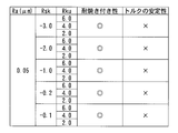
- FIG. 8 to FIG. 11 show the results of evaluation according to the above-described temperature rise test and rotational torque test in various combinations of the arithmetic average roughness Ra, the roughness curve skewness Rsk, and the roughness curve kurtosis Rku.
- the large ridge surface is finished with a particularly smooth surface property, and therefore the skewness Rsk of the roughness curve on the large ridge surface is Regardless of whether it is in the range of ⁇ 1.0 ⁇ Rsk ⁇ ⁇ 0.3, and whether or not the kurtosis Rku of the roughness curve is in the range of 3.0 ⁇ Rku ⁇ 5.0. It can be seen that the seizure resistance is particularly good while the torque stability is particularly poor.
- the large ridge surface has a particularly rough surface property, and the skewness Rsk of the roughness curve on the large ridge surface is ⁇ 1.0 ⁇ Regardless of whether or not Rsk ⁇ ⁇ 0.3, and whether the roughness curve kurtosis Rku is within the range of 3.0 ⁇ Rku ⁇ 5.0, the seizure resistance is high. It can be seen that the torque stability is particularly improved while it is particularly worse.
- the tapered roller bearing according to the present invention is suitable for an application for supporting a shaft provided in a power transmission device of an automobile, for example, a differential, a transmission, or the like. This is because a low speed rotation habituation operation is performed in a state where a preload is applied to the tapered roller bearing supporting the shaft.
- An example of the tapered roller bearing according to the above-described embodiment incorporated in the power transmission path of the automobile is shown in FIG.
- FIG. 12 is an example of a differential that is a component of a power transmission path of an automobile.
- the differential includes a drive pinion 104 rotatably supported by two tapered roller bearings 102 and 103 with respect to the housing 101, a ring gear 105 that meshes with the drive pinion 104, and a pair of tapered rollers to which the ring gear 105 is attached.
- a differential gear case 107 rotatably supported with respect to the housing 101 by a bearing 106, a pinion 108 disposed in the differential gear case 107, and a pair of side gears 109 meshing with the pinion 108; These are accommodated in a housing 101 in which gear oil is enclosed.
- This gear oil also serves as a lubricating oil for the tapered roller bearings 102, 103 and 106.
- Each tapered roller bearing 102, 103, 106 corresponds to the above-described embodiment.
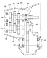
- FIG. 13 shows another example of the tapered roller bearing according to the above-described embodiment incorporated in the power transmission path of the automobile.
- FIG. 13 is an example of a transmission that is a component of a power transmission path of an automobile.
- the transmission shown in FIG. 13 is a multi-stage transmission that changes the gear ratio step by step.
- the rolling bearings 203 to 208 that rotatably support the rotation shafts (for example, the input shaft 201 and the output shaft 202) are described above.
- the tapered roller bearing according to the embodiment is provided.
- the illustrated transmission includes an input shaft 201 to which engine rotation is input, an output shaft 202 provided in parallel with the input shaft 201, and a plurality of gear trains 209 to 212 that transmit the rotation from the input shaft 201 to the output shaft 202. And a clutch (not shown) incorporated between each of the gear trains 209 to 212 and the input shaft 201 or the output shaft 202.
- the transmission switches the gear trains 209 to 212 to be used by selectively engaging the clutch, and changes the transmission gear ratio transmitted from the input shaft 201 to the output shaft 202.
- the rotation of the output shaft 202 is output to the output gear 213, and the rotation of the output gear 213 is transmitted to a differential gear or the like.
- the input shaft 201 and the output shaft 202 are rotatably supported by corresponding tapered roller bearings 203 and 204 or tapered roller bearings 205 and 206, respectively.
- the transmission is splashed or sprayed by lubricating oil splashed with the rotation of a gear or by spraying lubricating oil from a nozzle (not shown) provided inside the housing 214. Is applied to the side surface of each tapered roller bearing 203-208.
Landscapes
- Engineering & Computer Science (AREA)
- General Engineering & Computer Science (AREA)
- Mechanical Engineering (AREA)
- Rolling Contact Bearings (AREA)
Abstract
A conical roller bearing for which the arithmetic mean roughness Ra of a large-flange surface (12) of an inner ring (10) is 0.1 μm ≤ Ra ≤ 0.2 μm, the arithmetic mean roughness Ra of a roller large-end surface (33) is 0.1 μm or less, the skewness Rsk of a roughness curve of the large-flange surface (12) is −1.0 ≤ Rsk ≤ −3.0, the kurtosis Rku of the roughness curve of the large-flange surface (12) is 3.0 ≤ Rku ≤ 5.0, and the large-flange surface (12) is defined by a straight-line generatrix or a generatrix for which a middle concavity or a middle convexity is 1 μm or less.
Description
この発明は、円すいころ軸受に関する。
This invention relates to a tapered roller bearing.
円すいころ軸受では、円すいころのころ大端面と内輪の大鍔面とがすべり接触する。ころ大端面と大鍔面が金属接触することによる焼付きを防ぐため、これら両面間の油膜形成が良好になるように大鍔面の表面粗さを調整する取組みが実施されてきた。
In tapered roller bearings, the roller large end surface of the tapered roller and the large collar surface of the inner ring make sliding contact. In order to prevent seizure due to the metal contact between the roller large end face and the large collar surface, efforts have been made to adjust the surface roughness of the large collar surface so as to improve the oil film formation between these two surfaces.
また、円すいころ軸受を自動車の動力伝達経路、産業機械等の装置に使用する場合、円すいころ軸受の剛性や回転精度の向上を目的として予圧が負荷される。この場合、円すいころ軸受の回転トルクを測定して適正な予圧を判断する操作が必要である。その測定では、相手装置への組み込み工程の都合上から、低速(通常、100r/min以下)で回転させる状態で回転トルクを測定する。円すいころ軸受が低速で回転するとき、円すいころ軸受の回転トルクの発生要因の大部分は、円すいころのころ大端面と内輪の大鍔面とのすべり摩擦であり、円すいころと内輪と外輪の間に発生する転がり摩擦などによるトルクの影響はかなり小さい。したがって、円すいころ軸受の回転トルクを正確に測定するには、円すいころのころ大端面が内輪の大鍔面に接触した状態(即ち、軸受幅寸法が安定した状態)になるまで、予圧を付与しながら低速回転で充分に馴らし運転を行なう必要がある。
Also, when a tapered roller bearing is used in an apparatus such as a power transmission path of an automobile or an industrial machine, a preload is applied for the purpose of improving the rigidity and rotational accuracy of the tapered roller bearing. In this case, it is necessary to measure the rotational torque of the tapered roller bearing and determine an appropriate preload. In the measurement, the rotational torque is measured in a state where it is rotated at a low speed (usually 100 r / min or less) for the convenience of the incorporation process into the counterpart device. When tapered roller bearings rotate at low speed, most of the factors that generate torque in tapered roller bearings are sliding friction between the tapered end of the tapered roller and the large collar surface of the inner ring. The influence of torque due to rolling friction generated between them is quite small. Therefore, to accurately measure the rotational torque of a tapered roller bearing, preload is applied until the roller large end surface of the tapered roller is in contact with the large collar surface of the inner ring (that is, the bearing width dimension is stable). However, it is necessary to perform the operation at a low speed.
下記特許文献1に開示された円すいころ軸受は、内輪の大鍔面と円すいころのころ大端面間での潤滑状態を適正な状態に保つため、大鍔面の表面粗さRaを0.05~0.20μmの範囲に形成している。
The tapered roller bearing disclosed in Patent Document 1 below has a surface roughness Ra of 0.05 mm to maintain a proper lubrication state between the large collar surface of the inner ring and the large roller end surface of the tapered roller. It is formed in a range of ˜0.20 μm.
すなわち、大鍔面の表面粗さRaが0.05μm未満である場合、馴らし運転のとき、内輪の大鍔面と円すいころのころ大端面間の潤滑状態が、流体潤滑と境界潤滑の混合潤滑になるため、摩擦係数が大幅に変動し、測定される回転トルクのばらつきが大きくなり、予圧力の管理精度が悪くなる。大鍔面の表面粗さRaが0.05μm以上である場合、前記潤滑状態が境界潤滑となって摩擦係数が安定し、精度のよい予圧力の管理を行うことができる。100(r/min)を越える通常の軸受回転速度では、大鍔面ところ大端面間に十分な油膜が形成され、これら両面間の潤滑状態が流体潤滑となるため、摩擦係数が小さくなる。大鍔面の表面粗さRaが0.20μmを越えると、高速回転領域で軸受部が温度上昇し、潤滑油が粘度低下したときに、大鍔面ところ大端面間の油膜厚さが不十分となるため、焼付きの発生に注意が必要である。
That is, when the surface roughness Ra of the large collar surface is less than 0.05 μm, the lubrication state between the large collar surface of the inner ring and the roller large end surface of the tapered roller during mixed-in operation is a mixed lubrication of fluid lubrication and boundary lubrication. As a result, the friction coefficient fluctuates greatly, the variation in the measured rotational torque increases, and the preload management accuracy deteriorates. When the surface roughness Ra of the large collar surface is 0.05 μm or more, the lubrication state becomes boundary lubrication, the friction coefficient is stabilized, and the preload can be managed with high accuracy. At a normal bearing rotation speed exceeding 100 (r / min), a sufficient oil film is formed between the large end surface and the large end surface, and the lubrication state between both surfaces is fluid lubrication, so that the friction coefficient becomes small. When the surface roughness Ra of the large collar surface exceeds 0.20 μm, the bearing film temperature rises in the high-speed rotation region, and when the lubricating oil drops in viscosity, the oil film thickness between the large collar surface and the large end surface is insufficient. Therefore, attention should be paid to the occurrence of seizure.
また、下記特許文献2に開示された円すいころ軸受は、円すいころのころ大端面の表面粗さRaを0.1μm以下に形成し、かつ内輪の大鍔面の表面粗さRaを0.2μm以下に形成することにより、馴らし運転での回転トルクの安定性を向上させている。
Further, the tapered roller bearing disclosed in Patent Document 2 below has a tapered roller having a roller large end surface with a surface roughness Ra of 0.1 μm or less, and an inner ring having a large flange surface with a surface roughness Ra of 0.2 μm. By forming the following, the stability of the rotational torque in the habituation operation is improved.
特許文献1、2の円すいころ軸受は、予圧設定時の低速回転時における回転トルクを安定化させるため、内輪の大鍔面の表面粗さRaの範囲を規定しているが、どちらの円すいころ軸受も、超仕上げ水準の粗さ範囲(例えばRaが0.08μm以下)が含まれている。超仕上げ水準の粗さでは、回転トルクが不安定になることがある。
The tapered roller bearings of Patent Documents 1 and 2 define the range of the surface roughness Ra of the large collar surface of the inner ring in order to stabilize the rotational torque during low-speed rotation when preload is set. The bearing also includes a super-finished roughness range (for example, Ra is 0.08 μm or less). At super-finished roughness, the rotational torque may become unstable.
一方、内輪の大鍔面の表面粗さRaを超仕上げ水準の粗さ範囲よりも粗くすれば、低速回転時における回転トルクを安定化させることができると考えられるが、超仕上げ水準の粗さ範囲とした場合よりも耐焼付き性が劣る。
On the other hand, if the surface roughness Ra of the large collar surface of the inner ring is made rougher than the roughness range of the superfinishing level, it is considered that the rotational torque during low-speed rotation can be stabilized. The seizure resistance is inferior to the range.
このように、大鍔面の単純な表面粗さRaの設定では、低速回転時における回転トルクの安定化と、大鍔面ところ大端面間の耐焼付き性とを両立させることが困難である。
As described above, it is difficult to achieve both the stabilization of the rotational torque during low-speed rotation and the seizure resistance between the large flange surface and the large end surface by setting the simple surface roughness Ra of the large flange surface.
上述の背景に鑑み、この発明が解決しようとする課題は、円すいころ軸受において、低速回転時の回転トルクの安定性と、大鍔面ところ大端面間の耐焼付き性とを両立させることである。
In view of the above-described background, the problem to be solved by the present invention is to achieve both the stability of rotational torque during low-speed rotation and the seizure resistance between the large flange surface and the large end surface in a tapered roller bearing. .
上記の課題を達成するため、この発明は、ころ大端面を有する円すいころと、前記ころ大端面と摺接する大鍔面を有する内輪と、を備える円すいころ軸受において、前記大鍔面の算術平均粗さRaは0.1μm≦Ra≦0.2μmであり、前記大鍔面の粗さ曲線のスキューネスRskは-1.0≦Rsk≦-0.3であり、前記大鍔面の粗さ曲線のクルトシスRkuは3.0≦Rku≦5.0である構成を採用した。
In order to achieve the above object, the present invention provides a tapered roller bearing comprising a tapered roller having a roller large end surface and an inner ring having a large collar surface in sliding contact with the roller large end surface, the arithmetic average of the large collar surface The roughness Ra is 0.1 μm ≦ Ra ≦ 0.2 μm, the skewness Rsk of the roughness surface of the large ridge surface is −1.0 ≦ Rsk ≦ −0.3, and the roughness curve of the large ridge surface is The configuration of the kurtosis Rku of 3.0 ≦ Rku ≦ 5.0 was adopted.
この発明における算術平均粗さRaは、日本工業規格(JIS) B0601:2013で規定される算術平均粗さRaのことをいう。また、この発明における粗さ曲線のスキューネスRskは、日本工業規格(JIS) B0601:2013で規定される粗さ曲線のスキューネスRskのことをいう。また、この発明における粗さ曲線のクルトシスRkuは、日本工業規格(JIS) B0601:2013で規定される粗さ曲線のクルトシスRkuのことをいう。
The arithmetic average roughness Ra in the present invention refers to the arithmetic average roughness Ra defined by Japanese Industrial Standard (JIS) B0601: 2013. Further, the skewness Rsk of the roughness curve in the present invention refers to the skewness Rsk of the roughness curve defined by Japanese Industrial Standard (JIS) B0601: 2013. Further, the kurtosis Rku of the roughness curve in the present invention refers to the kurtosis Rku of the roughness curve defined by Japanese Industrial Standard (JIS) B0601: 2013.
上記構成によれば、内輪の大鍔面の算術平均粗さRaを0.1~0.2μmの範囲にしているので、円すいころ軸受の低速回転時:0~200(r/min)の範囲における回転トルクを安定化させるのに好適な特性となる。これだけでは、耐焼付き性が超仕上げ水準の粗さより劣ってしまうため、この発明では、さらに、大鍔面の粗さ曲線の表面性状の特性を規定する。
すなわち、粗さ曲線のスキューネスRsk<0の場合、平均線に対して上側に偏っている特性になるので、大鍔面のRskをマイナスの数値範囲にすることにより、大鍔面が平面を有する特性になり、油膜形成に有利に働く表面性状となる。そこで、大鍔面の粗さ曲線のスキューネスRskは、-1.0~-0.3とする。
さらに、粗さ曲線のクルトシスRkuが3より小さい場合、表面凸凹の高さ分布がつぶれているような形状となるが、回転トルクの安定化を図るためには粗さの突起も必要となる。そこで、大鍔面の粗さ曲線のクルトシスRkuは、3.0~5.0とする。
前述のRa、Rsk及びRkuの範囲とした特性バランスの大鍔面にすれば、低速回転時の回転トルクの安定性と、大鍔面ところ大端面間の耐焼付き性との両立を実現することができる。 According to the above configuration, since the arithmetic average roughness Ra of the large collar surface of the inner ring is in the range of 0.1 to 0.2 μm, the tapered roller bearing is rotated at a low speed: in the range of 0 to 200 (r / min). This is a characteristic suitable for stabilizing the rotational torque at. This alone will cause the seizure resistance to be inferior to the roughness of the superfinishing level, and therefore the present invention further defines the surface texture characteristics of the roughness curve of the large surface.
That is, when the skewness Rsk <0 of the roughness curve, the characteristic is biased to the upper side with respect to the average line. Therefore, by setting the Rsk of the large surface to a negative numerical range, the large surface has a flat surface. It becomes a characteristic, and it becomes the surface property which works favorably for oil film formation. Accordingly, the skewness Rsk of the roughness curve of the large ridge surface is set to -1.0 to -0.3.
Further, when the kurtosis Rku of the roughness curve is smaller than 3, the shape of the surface unevenness distribution is crushed, but a roughness protrusion is also required to stabilize the rotational torque. Therefore, the kurtosis Rku of the roughness curve of the large ridge surface is set to 3.0 to 5.0.
If the characteristic balance in the range of Ra, Rsk, and Rku described above is used, the stability of rotational torque during low-speed rotation and the seizure resistance between the large flange surface and the large end surface can be realized. Can do.
例えば、前記ころ大端面の算術平均粗さRaは0.1μm以下であればよい。ころ大端面の表面粗さは、内輪の大鍔面の表面粗さより機能への影響が少ないため、スキューネスRsk、クルトシスRkuを更に規定するまでもなく、算出平均粗さRaで単純に管理すればよい。
For example, the arithmetic average roughness Ra of the roller large end face may be 0.1 μm or less. Since the surface roughness of the roller large end face has less influence on the function than the surface roughness of the large collar surface of the inner ring, it is not necessary to further define the skewness Rsk and kurtosis Rku, and can be managed simply by the calculated average roughness Ra. Good.
例えば、前記大鍔面は、直線の母線、又は中凹若しくは中凸が1μm以内の母線で規定される形状であればよい。ころ大端面と大鍔面は、理想的には、球面と平面の接触関係であるとき、特に良好な耐焼付き性を実現することができる。このため、大鍔面の母線形状は、工業製品で得られる程度の概略直線状であることが好ましい。大鍔面が中凹又は中凸の母線形状をもつ場合、中凹又は中凸の量が1μmを超えると、良好な潤滑油のくさび効果を得ることができない。
For example, the large ridge surface may be a shape defined by a straight bus bar or a bus bar having a central recess or convexity of 1 μm or less. Ideally, the roller large end face and the large collar surface can realize particularly good seizure resistance when the spherical surface and the flat surface are in a contact relationship. For this reason, it is preferable that the bus bar shape of the large ridge surface is a substantially linear shape to the extent that it can be obtained with industrial products. When the large corrugated surface has a generatrix shape that is concave or convex, if the amount of the concave or convex portion exceeds 1 μm, a good lubricating oil wedge effect cannot be obtained.
この発明に係る円すいころ軸受は、自動車の動力伝達装置に組み込まれるものに好適である。自動車の動力伝達装置は、自動車の駆動源からの動力を車輪まで伝達する経路を構成する要素であり、例えば、デファレンシャル、トランスミッション等が挙げられる。
The tapered roller bearing according to the present invention is suitable for those incorporated in a power transmission device of an automobile. An automobile power transmission device is an element that constitutes a path for transmitting power from a driving source of an automobile to wheels, and includes, for example, a differential, a transmission, and the like.
上述のように、この発明は、上記構成の採用により、円すいころ軸受において、低速回転時の回転トルクの安定性と、大鍔面ところ大端面間の耐焼付き性とを両立させることができる。
As described above, according to the present invention, by adopting the above configuration, in the tapered roller bearing, it is possible to achieve both stability of rotational torque during low-speed rotation and seizure resistance between the large collar surface and the large end surface.
この発明の実施形態に係る円すいころ軸受を添付図面の図1、図2に基づいて説明する。
図1に示すように、実施形態に係る円すいころ軸受1は、内輪10と、外輪20と、複数の円すいころ30と、これら円すいころ30を保持する保持器40とを備える。 A tapered roller bearing according to an embodiment of the present invention will be described with reference to FIGS. 1 and 2 of the accompanying drawings.
As shown in FIG. 1, the tapered roller bearing 1 according to the embodiment includes aninner ring 10, an outer ring 20, a plurality of tapered rollers 30, and a cage 40 that holds these tapered rollers 30.
図1に示すように、実施形態に係る円すいころ軸受1は、内輪10と、外輪20と、複数の円すいころ30と、これら円すいころ30を保持する保持器40とを備える。 A tapered roller bearing according to an embodiment of the present invention will be described with reference to FIGS. 1 and 2 of the accompanying drawings.
As shown in FIG. 1, the tapered roller bearing 1 according to the embodiment includes an
内輪10、外輪20、円すいころ30は、それぞれ鋼によって形成されている。
The inner ring 10, the outer ring 20, and the tapered roller 30 are each made of steel.
内輪10、外輪20は、それぞれ同軸に配置された環状の軸受部品になっている。内輪10は、外側に軌道11と、大鍔面12とを有する。外輪20は、内側に軌道21を有する。軌道11、21は、それぞれ円すい面状に形成されている。
The inner ring 10 and the outer ring 20 are annular bearing parts arranged coaxially. The inner ring 10 has a track 11 and a large collar surface 12 on the outside. The outer ring 20 has a track 21 inside. The tracks 11 and 21 are each formed in a conical surface shape.
円すいころ30は、円すい面状の転動面31と、ころ小端面32と、ころ大端面33とを有する。転動面31は、内輪10の軌道11と外輪20の軌道21との間に介在する。ころ小端面32は、円すいころ30の小径側の側面である。ころ大端面33は、円すいころ30の大径側の側面である。
The tapered roller 30 includes a tapered rolling surface 31, a small roller end surface 32, and a large roller end surface 33. The rolling surface 31 is interposed between the track 11 of the inner ring 10 and the track 21 of the outer ring 20. The roller small end surface 32 is a side surface on the small diameter side of the tapered roller 30. The roller large end surface 33 is a side surface on the large diameter side of the tapered roller 30.
ころ大端面33は、球面状になっている。
The roller large end face 33 has a spherical shape.
ころ大端面33の表面粗さは、内輪10の大鍔面12の粗さより耐焼付き性等の機能への影響が少ない。このため、ころ大端面33の表面粗さは、単純に算術平均粗さRaで管理すればよい。具体的には、ころ大端面33の算術平均粗さRaは、0.1μm以下であればよい。ここで、算術平均粗さRaは、日本工業規格(JIS) B0601:2013の4.2.1で規定される算術平均粗さRaのことである。算術平均粗さRaの単位は、μmである。
The surface roughness of the roller large end surface 33 has less influence on functions such as seizure resistance than the roughness of the large collar surface 12 of the inner ring 10. For this reason, what is necessary is just to manage the surface roughness of the roller large end surface 33 by arithmetic mean roughness Ra simply. Specifically, the arithmetic average roughness Ra of the roller large end face 33 may be 0.1 μm or less. Here, the arithmetic average roughness Ra is the arithmetic average roughness Ra defined in 4.2.1 of Japanese Industrial Standard (JIS) B0601: 2013. The unit of arithmetic average roughness Ra is μm.
図2に示すように、内輪10の大鍔面12は、円すいころ30のころ大端面33と摺接する。すなわち、大鍔面12は、軸受回転中にころ大端面33とすべり接触し得る内輪表面部分である。大鍔面12は、直線の母線で規定される形状(すなわち円すい面状)に形成されている。
2, the large collar surface 12 of the inner ring 10 is in sliding contact with the roller large end surface 33 of the tapered roller 30. That is, the large collar surface 12 is an inner ring surface portion that can come into sliding contact with the roller large end surface 33 during bearing rotation. The large collar surface 12 is formed in a shape (that is, a conical surface shape) defined by a straight generatrix.
大鍔面12は、図3に示すように、中凹が1μm以内の母線で規定される形状でもよいし、図4に示すように、中凸が1μm以内の母線で規定される形状でもよい。ここで、中凹とは、大鍔面12の母線の両端p1とp2を結ぶ仮想の基準直線(図中に一点鎖線で示す)を考えたとき、p1、p2から基準直線の中央に向かって、次第にころ大端面33から遠ざかる方へ凹んだ形状のことをいう。また、中凸とは、前述のp1、p2から基準直線の中央に向かって、次第にころ大端面33に接近する方へ膨らんだ形状のことをいう。中凹又は中凸が1μm以内とは、その基準直線からの最大の凹み量又は膨らみ量Δlが1μm以内であることをいう。
As shown in FIG. 3, the large ridge surface 12 may have a shape defined by a bus bar having a center recess of 1 μm or less, or may have a shape defined by a bus bar having a center projection of 1 μm or less as shown in FIG. 4. . Here, when considering a virtual reference straight line (indicated by a one-dot chain line in the figure) connecting both ends p1 and p2 of the bus bar of the large collar surface 12, the center concave is from p1 and p2 toward the center of the reference straight line. The shape gradually dented away from the roller large end face 33. Further, the middle convex means a shape that gradually bulges toward the center of the reference straight line from the aforementioned p1 and p2 toward the roller large end face 33. The phrase “middle concave or middle convex is within 1 μm” means that the maximum concave amount or bulging amount Δl from the reference straight line is within 1 μm.
大鍔面12を直線の母線(図2参照)、又は中凹(図3参照)若しくは中凸(図4参照)が1μm以内の母線で規定される形状にすれば、ころ大端面33と大鍔面12を球面と平面の接触関係とする、又は、これと良く似た接触関係になるので、ころ大端面33と大鍔面12間で潤滑油の良好なくさび効果を実現することができる。
If the large collar surface 12 has a straight busbar (see FIG. 2), or a center recess (see FIG. 3) or a center convexity (see FIG. 4) defined by a bus within 1 μm, the large roller end face 33 and the large end surface 33 are large. Since the flange surface 12 has a contact relationship between the spherical surface and the flat surface or a contact relationship similar to this, a good wedge effect of the lubricating oil can be realized between the roller large end surface 33 and the large flange surface 12. .
大鍔面12の算術平均粗さRaは、0.1μm≦Ra≦0.2μmである。大鍔面12の算術平均粗さRaを0.1~0.2μmとすることにより、大鍔面12は、図1に示す円すいころ軸受1の低速回転時:0~200(r/min)の範囲において回転トルクを安定化させるのに好適な特性となる。
The arithmetic average roughness Ra of the large surface 12 is 0.1 μm ≦ Ra ≦ 0.2 μm. By setting the arithmetic average roughness Ra of the large flange surface 12 to 0.1 to 0.2 μm, the large flange surface 12 is rotated at a low speed of the tapered roller bearing 1 shown in FIG. 1: 0 to 200 (r / min) In this range, the characteristics are suitable for stabilizing the rotational torque.
大鍔面12の粗さ曲線のスキューネスRskは、-1.0≦Rsk≦-0.3である。ここで、粗さ曲線のスキューネスRskは、日本工業規格(JIS) B0601:2013の4.2.3で規定される粗さ曲線のスキューネスRskのことである。粗さ曲線のスキューネスRskは、次の式(1)によって定義されるものである。
The skewness Rsk of the roughness curve of the large surface 12 is −1.0 ≦ Rsk ≦ −0.3. Here, the skewness Rsk of the roughness curve is the skewness Rsk of the roughness curve defined in 4.2.3 of Japanese Industrial Standard (JIS) B0601: 2013. The skewness Rsk of the roughness curve is defined by the following equation (1).

粗さ曲線のスキューネスRskは、式(1)に示すように、断面曲線の二乗平均平方根粗さRqの三乗によって無次元化した基準長さにおけるZ(x)の三乗平均である。粗さ曲線のスキューネスRskは、輪郭曲線の確率密度関数の非対称性の度合いを示す数値であり、突出した山又は谷の影響を強く受けるパラメータである。図5に、スキューネスRsk>0を満足する粗さ曲線と、スキューネスRsk<0を満足する粗さ曲線を例示する。これら両粗さ曲線の比較から明らかなように、スキューネスRsk<0の場合、突出した山が比較的に少ない傾向の表面性状となるので、油膜が破れにくくなり、焼付きの防止に有利である。ただし、スキューネスRskの負の値が大きくなる程、谷の幅が広がり、突出した山が比較的に少ない傾向の表面(円すいころ軸受においては、ころの大端面と接触する内輪の大鍔面)が断続的となり、当該表面と谷との境界部分で応力集中が生じてしまうので、油膜形成が阻害される。図2に示す大鍔面12の粗さ曲線のスキューネスRskを-1.0~-0.3とすることにより、大鍔面12が平面を有する特性になり、油膜形成に有利に働く表面性状となる。
The skewness Rsk of the roughness curve is the cube average of Z (x) at the reference length made dimensionless by the cube of the root mean square roughness Rq of the cross-sectional curve, as shown in Equation (1). The skewness Rsk of the roughness curve is a numerical value indicating the degree of asymmetry of the probability density function of the contour curve, and is a parameter that is strongly influenced by the protruding peaks or valleys. FIG. 5 illustrates a roughness curve satisfying the skewness Rsk> 0 and a roughness curve satisfying the skewness Rsk <0. As is clear from the comparison of these two roughness curves, when the skewness Rsk <0, the surface properties tend to have relatively few protruding peaks, which makes it difficult for the oil film to break and is advantageous in preventing seizure. . However, the larger the negative value of the skewness Rsk, the wider the valley, and the surface with the tendency of relatively few protruding peaks (in the case of a tapered roller bearing, the large ring surface of the inner ring that contacts the large end surface of the roller). Becomes intermittent, and stress concentration occurs at the boundary between the surface and the valley, so that oil film formation is hindered. By setting the skewness Rsk of the roughness curve of the large ridge surface 12 shown in FIG. 2 to −1.0 to −0.3, the large ridge surface 12 has a flat surface characteristic, which is advantageous for oil film formation. It becomes.
また、大鍔面12の粗さ曲線のクルトシスRkuは、3.0≦Rku≦5.0である。ここで、粗さ曲線のクルトシスRkuは、日本工業規格(JIS) B0601:2013の4.2.4で規定される粗さ曲線のクルトシスRkuのことである。粗さ曲線のクルトシスRkuは、次の式(2)によって定義されるものである。
Further, the kurtosis Rku of the roughness curve of the large ridge surface 12 is 3.0 ≦ Rku ≦ 5.0. Here, the kurtosis Rku of the roughness curve refers to the kurtosis Rku of the roughness curve defined in Japanese Industrial Standards (JIS) B0601: 2013 4.2.4. The kurtosis Rku of the roughness curve is defined by the following equation (2).

粗さ曲線のクルトシスRkuは、式(2)に示すように、断面曲線の二乗平均平方根粗さRqの四乗によって無次元化した基準長さにおけるZ(x)の四乗平均である。粗さ曲線のクルトシスRkuは、輪郭曲線の確率密度関数のとがり(鋭さ)の度合いを示す数値であり、突出した山又は谷の影響を強く受けるパラメータである。図6に、クルトシスRku>3を満足する粗さ曲線と、クルトシスRku<3を満足する粗さ曲線とを例示する。これら両粗さ曲線の比較から明らかなように、クルトシスRku>3の場合、山が比較的に尖った傾向の表面性状となるので、適度な金属接触が起こり、トルク安定化に有利である。ただし、クルトシスRkuの正の値が大きくなる程、過度な金属接触が起こり、耐焼き付き性が悪化する。図2に示す大鍔面12の粗さ曲線のクルトシスRkuを3.0~5.0とすることにより、大鍔面12は、低速回転時における回転トルクの安定化を図るための粗さの突起をもった表面性状となる。
The kurtosis Rku of the roughness curve is the root mean square of Z (x) at the reference length made dimensionless by the square of the root mean square roughness Rq of the cross section curve, as shown in Equation (2). The kurtosis Rku of the roughness curve is a numerical value indicating the degree of sharpness (sharpness) of the probability density function of the contour curve, and is a parameter that is strongly influenced by protruding peaks or valleys. FIG. 6 illustrates a roughness curve satisfying Kurtosis Rku> 3 and a roughness curve satisfying Kurtosis Rku <3. As is apparent from the comparison of these two roughness curves, in the case of Kurtosis Rku> 3, the surface properties tend to have a relatively sharp peak, so that an appropriate metal contact occurs, which is advantageous for torque stabilization. However, as the positive value of kurtosis Rku increases, excessive metal contact occurs and the seizure resistance deteriorates. By setting the kurtosis Rku of the roughness curve of the large collar surface 12 shown in FIG. 2 to 3.0 to 5.0, the large collar surface 12 has a roughness for stabilizing the rotational torque during low-speed rotation. Surface texture with protrusions.
算術平均粗さRa、粗さ曲線のスキューネスRsk、及び粗さ曲線のクルトシスRkuは、いずれも表面粗さ測定機によって測定可能である。
Arithmetic mean roughness Ra, roughness curve skewness Rsk, and roughness curve kurtosis Rku can all be measured by a surface roughness measuring machine.
この円すいころ軸受1は、算術平均粗さRa:0.1~0.2μm、粗さ曲線のスキューネスRsk:-1.0~-0.3、及び粗さ曲線のクルトシスRku:3.0~5.0の範囲にある特性バランスの大鍔面12を採用しているので、低速回転時の回転トルクの安定性と、大鍔面12ところ大端面33間の耐焼付き性とを両立させることができる。
This tapered roller bearing 1 has an arithmetic average roughness Ra: 0.1 to 0.2 μm, a roughness curve skewness Rsk: −1.0 to −0.3, and a roughness curve kurtosis Rku: 3.0 to Since the large collar surface 12 having a characteristic balance in the range of 5.0 is adopted, both the stability of the rotational torque at the time of low speed rotation and the seizure resistance between the large collar surface 12 and the large end surface 33 are achieved. Can do.
なお、大鍔面12の算術平均粗さRaを0.1~0.2μmの範囲内とし、大鍔面12の粗さ曲線のスキューネスRsk及びクルトシスRkuをそれぞれ上述の範囲外とした場合、低速回転時の回転トルクを安定させることは可能であろうが、大鍔面12の算術平均粗さRaを0.1μm未満とした場合より耐焼付き性が劣る。
Note that when the arithmetic average roughness Ra of the large collar surface 12 is in the range of 0.1 to 0.2 μm, and the skewness Rsk and the kurtosis Rku of the roughness curve of the large collar surface 12 are outside the above ranges, respectively, the speed is low. Although it may be possible to stabilize the rotational torque at the time of rotation, the seizure resistance is inferior to the case where the arithmetic average roughness Ra of the large collar surface 12 is less than 0.1 μm.
また、上述の特性バランスを有する大鍔面12を研削仕上げにすると、粗さ規定範囲が細か過ぎて加工抵抗が大き過ぎることから、研削焼けの懸念が生じる。表面粗さRa:0.1~0.2μmの粗さ水準を研削仕上げで達成するには、超仕上げ加工と比べて目の粗い砥石を用いた研削加工を行うことになり、加工抵抗が大き過ぎるのである。それ故、大鍔面12は、研削加工で仕上げることが困難であるから、超仕上げ加工を活用して上述の特性バランスを有するように加工すればよい。例えば、大鍔面12に超短時間(0.5秒から2秒)で超仕上げ加工を施すことにより、上述の特性バランスを実現することが可能である。
Also, if the large flange surface 12 having the above-mentioned characteristic balance is ground, the roughness regulation range is too fine and the processing resistance is too large, which may cause grinding burn. Surface roughness Ra: In order to achieve a roughness level of 0.1 to 0.2 μm by grinding, grinding using a grindstone with a coarser surface is required compared to super-finishing, resulting in high machining resistance. It is over. Therefore, since the large flange surface 12 is difficult to finish by grinding, it may be processed so as to have the above-mentioned property balance by utilizing super finishing. For example, the above-mentioned characteristic balance can be realized by performing superfinishing on the large collar surface 12 in a very short time (0.5 second to 2 seconds).
実施例及び比較例1、2を用い、回転トルク試験と、昇温試験とを行った。実施例及び比較例1、2は、いずれも型番30307Dの円すいころ軸受である。
Using the examples and comparative examples 1 and 2, a rotational torque test and a temperature rise test were performed. Examples and Comparative Examples 1 and 2 are all tapered roller bearings of model number 30307D.
実施例は、上述の実施形態に属するものであって、大鍔面の算術平均粗さRaを0.149μmとし、大鍔面の粗さ曲線のスキューネスRskを-0.96とし、大鍔面の粗さ曲線のクルトシスRkuを4.005としたものである。
The example belongs to the above-described embodiment, and the arithmetic average roughness Ra of the large corrugated surface is 0.149 μm, the skewness Rsk of the roughness curve of the large corrugated surface is −0.96, and the large corrugated surface is The kurtosis Rku of the roughness curve is 4.005.
比較例1は、大鍔面の算術平均粗さRaを0.2μmとしたものである。
In Comparative Example 1, the arithmetic average roughness Ra of the large surface is 0.2 μm.
比較例2は、大鍔面の算術平均粗さRaを0.08μmとしたもの、すなわち大鍔面を超仕上げ水準としたものである。
Comparative Example 2 is one in which the arithmetic mean roughness Ra of the large corrugated surface is 0.08 μm, that is, the large corrugated surface is a super-finished level.
比較例1の大鍔面の粗さ曲線のスキューネスRskは、-1.053であり、比較例1の大鍔面の粗さ曲線のクルトシスRkuは、2.563である。比較例2の大鍔面の粗さ曲線のスキューネスRskは、-1.298であり、比較例2の大鍔面の粗さ曲線のクルトシスRkuは、5.103である。
The skewness Rsk of the roughness curve of the large ridge surface of Comparative Example 1 is −1.053, and the kurtosis Rku of the roughness curve of the large ridge surface of Comparative Example 1 is 2.563. The skewness Rsk of the roughness curve of the large ridge surface of Comparative Example 2 is −1.298, and the kurtosis Rku of the roughness curve of the large ridge surface of Comparative Example 2 is 5.103.
実施例及び比較例1、2のころ大端面は、算術平均粗さRaが同等であって0.1μm以下である。
The roller large end surfaces of Examples and Comparative Examples 1 and 2 have the same arithmetic average roughness Ra and 0.1 μm or less.
実施例及び比較例1、2で実施した回転トルク試験の条件は、共通である。その回転トルク試験において、1分当たりの回転数(r/min)は、0~200の範囲である。また、軸受に塗布された防錆油の潤滑条件は、40℃の動粘度が16.5mm2/sであり、100℃の動粘度が3.5mm2/sである。
The conditions of the rotational torque test performed in the example and comparative examples 1 and 2 are common. In the rotational torque test, the number of revolutions per minute (r / min) is in the range of 0 to 200. Moreover, the lubrication conditions of the rust preventive oil applied to the bearing are a kinematic viscosity at 40 ° C. of 16.5 mm 2 / s and a kinematic viscosity at 100 ° C. of 3.5 mm 2 / s.
回転トルク試験の結果を図7に示す。図7の実施例及び比較例1、2の測定結果を見比べれば明らかなように、実施例は、大鍔面の算術平均粗さRaが0.2μmである比較例1と略同等の安定したトルク特性を示した。これは、実施例の低速回転領域において、大鍔面ところ大端面間での潤滑油のくさび効果が小さく、これら両面間の油膜が薄く、これら両面間が200r/minまで境界潤滑となる(混合潤滑でない)ことから、実施例が安定したトルク特性を有すると考えられる。
Fig. 7 shows the results of the rotational torque test. As is clear from the comparison of the measurement results of the example of FIG. 7 and comparative examples 1 and 2, the example has substantially the same stability as that of comparative example 1 in which the arithmetic mean roughness Ra of the large surface is 0.2 μm. Torque characteristics are shown. This is because the wedge effect of the lubricating oil between the large flange surface and the large end surface is small in the low-speed rotation region of the embodiment, the oil film between these both surfaces is thin, and boundary lubrication between these both surfaces reaches 200 r / min (mixed) Therefore, it is considered that the example has a stable torque characteristic.
一方、大鍔面の算術平均粗さRaが0.08μmである比較例2は、50r/minまでに急激にトルク値が低下する。これは、比較例2の大鍔面の粗さが細かいために50r/minまでに十分な油膜厚さが形成された結果であり、50r/min以降は転動面の転がり抵抗が支配的となると考えられる。実機組立後の予圧管理(あるいはトルクチェック)は10~50r/minの範囲で行う事例が多く、この範囲でのトルクを安定化できる実施例は、実機組立性が良いと言える。
On the other hand, in Comparative Example 2 in which the arithmetic average roughness Ra of the large surface is 0.08 μm, the torque value rapidly decreases by 50 r / min. This is a result of forming a sufficient oil film thickness by 50 r / min because the roughness of the large collar surface of Comparative Example 2 is fine, and the rolling resistance of the rolling surface is dominant after 50 r / min. It is considered to be. In many cases, preload management (or torque check) after assembling the actual machine is performed in the range of 10 to 50 r / min, and the embodiment capable of stabilizing the torque in this range is said to have good assemblability.
昇温試験に用いた実施例及び比較例1、2は、それぞれ回転トルク試験と同一の製造ロットのものである。実施例及び比較例1、2で実施した昇温試験の条件は、共通である。その昇温試験において、ラジアル荷重17kN、アキシアル荷重1.5kNを軸受に負荷した。また、潤滑条件は、タービン油VG56を用い、軸心油浴とした。昇温試験は、所定の軸受回転数で外輪温度を測定して昇温を確認した。その測定において、120℃以下であったときは、評価を「○」とし、120℃を超え150℃未満であったときは、評価を「△」とし、150℃以上であったときは、評価を「×」とした。昇温試験の結果を表1に示す。
Example and Comparative Examples 1 and 2 used for the temperature rise test are of the same production lot as the rotational torque test. The conditions of the temperature increase test performed in the examples and comparative examples 1 and 2 are common. In the temperature increase test, a radial load of 17 kN and an axial load of 1.5 kN were applied to the bearing. The lubricating conditions were turbine oil VG56 and an axial center oil bath. In the temperature increase test, the temperature increase was confirmed by measuring the outer ring temperature at a predetermined bearing rotation speed. In the measurement, when it was 120 ° C. or lower, the evaluation was “◯”, when it was higher than 120 ° C. and lower than 150 ° C., the evaluation was “Δ”, and when it was 150 ° C. or higher, the evaluation was Was marked “x”. Table 1 shows the results of the temperature increase test.

表1を見れば明らかなように、実施例は、大鍔面の算術平均粗さRaが0.08μmである比較例2と同水準の耐焼付き性を有することを示した。
As is apparent from Table 1, the example showed that it had the same level of seizure resistance as Comparative Example 2 in which the arithmetic average roughness Ra of the large surface was 0.08 μm.
算術平均粗さRa、粗さ曲線のスキューネスRsk、及び粗さ曲線のクルトシスRkuの様々な組み合わせにおいて、上述の昇温試験及び回転トルク試験に準じて評価した結果を図8~図11に示す。
FIG. 8 to FIG. 11 show the results of evaluation according to the above-described temperature rise test and rotational torque test in various combinations of the arithmetic average roughness Ra, the roughness curve skewness Rsk, and the roughness curve kurtosis Rku.
図8に示すように、大鍔面における算術平均粗さRaが0.05の場合、大鍔面が特に滑らかな表面性状に仕上げられているので、大鍔面における粗さ曲線のスキューネスRskが-1.0≦Rsk≦-0.3の範囲にあるか否かを問わず、また、粗さ曲線のクルトシスRkuが3.0≦Rku≦5.0の範囲にあるか否かを問わず、耐焼付き性が特に良好になる一方、トルクの安定性が特に悪くなることが分かる。
As shown in FIG. 8, when the arithmetic average roughness Ra on the large ridge surface is 0.05, the large ridge surface is finished with a particularly smooth surface property, and therefore the skewness Rsk of the roughness curve on the large ridge surface is Regardless of whether it is in the range of −1.0 ≦ Rsk ≦ −0.3, and whether or not the kurtosis Rku of the roughness curve is in the range of 3.0 ≦ Rku ≦ 5.0. It can be seen that the seizure resistance is particularly good while the torque stability is particularly poor.
図9、図10に示すように、大鍔面における算術平均粗さRa=0.1又は0.2の場合、Ra=0.05の場合に比べて、耐焼付き性が悪化傾向を示し、トルクの安定性が改善傾向を示す。ここで、大鍔面における粗さ曲線のスキューネスRsk<-1.0の場合、油膜が形成されにくく、耐焼付き性に不利となることが分かる。一方、大鍔面における粗さ曲線のスキューネスRsk>-0.3の場合、以下に示す大鍔面における粗さ曲線のクルトシスRkuの特性との兼ね合いによって、耐焼き付き性とトルクの安定性とを両立することができない。また、大鍔面における粗さ曲線のクルトシスRku<3の場合、油膜が出来過ぎて、トルクの安定性に不利となることが分かる。一方、大鍔面における粗さ曲線のクルトシスRku>5の場合、表面の微小な山々が尖り過ぎてころ大端面と金属接触し易く、油膜が出来にくくなって、耐焼付き性に不利となることが分かる。
As shown in FIG. 9 and FIG. 10, when the arithmetic average roughness Ra = 0.1 or 0.2 on the large ridge surface, the seizure resistance tends to deteriorate compared to the case of Ra = 0.05, Torque stability shows a trend of improvement. Here, it is understood that when the skewness Rsk <−1.0 of the roughness curve on the large ridge surface, it is difficult to form an oil film, which is disadvantageous for seizure resistance. On the other hand, when the skewness Rsk of the roughness curve on the large ridge surface is greater than −0.3, the seizure resistance and the stability of torque are reduced by the balance with the characteristics of the kurtosis Rku of the roughness curve on the large ridge surface shown below. Cannot balance. Further, it is understood that when the kurtosis Rku <3 of the roughness curve on the large ridge surface, an oil film is formed too much, which is disadvantageous for torque stability. On the other hand, when the kurtosis Rku> 5 of the roughness curve on the large ridge surface, the minute peaks on the surface are too sharp and it is easy to make metal contact with the roller large end surface, making it difficult to form an oil film, which is disadvantageous for seizure resistance. I understand. *
図11に示すように、大鍔面における算術平均粗さRaが0.25の場合、大鍔面が特に粗い表面性状になり、大鍔面における粗さ曲線のスキューネスRskが-1.0≦Rsk≦-0.3の範囲にあるか否かを問わず、また、粗さ曲線のクルトシスRkuが3.0≦Rku≦5.0の範囲にあるか否かを問わず、耐焼付き性が特に悪くなる一方、トルクの安定性が特に良くなることが分かる。
As shown in FIG. 11, when the arithmetic average roughness Ra on the large ridge surface is 0.25, the large ridge surface has a particularly rough surface property, and the skewness Rsk of the roughness curve on the large ridge surface is −1.0 ≦ Regardless of whether or not Rsk ≦ −0.3, and whether the roughness curve kurtosis Rku is within the range of 3.0 ≦ Rku ≦ 5.0, the seizure resistance is high. It can be seen that the torque stability is particularly improved while it is particularly worse.
図8~図11の評価結果を総合すると、大鍔面の算術平均粗さRaは0.1μm≦Ra≦0.2μmである場合、大鍔面の粗さ曲線のスキューネスRskが-1.0≦Rsk≦-0.3であり、かつ大鍔面の粗さ曲線のクルトシスRkuが3.0≦Rku≦5.0であれば、耐焼付き性とトルクの安定性の両立を図ることが可能であると分かる。
8 to 11, when the arithmetic average roughness Ra of the large ridge surface is 0.1 μm ≦ Ra ≦ 0.2 μm, the skewness Rsk of the large ridge surface roughness curve is −1.0. ≦ Rsk ≦ −0.3, and if the kurtosis Rku of the roughness curve of the large rib surface is 3.0 ≦ Rku ≦ 5.0, it is possible to achieve both seizure resistance and torque stability. I understand that.
この発明に係る円すいころ軸受は、自動車の動力伝達装置、例えば、デファレンシャル、トランスミッション等に備わる軸を支持する用途等に好適である。これは、その軸を支持する円すいころ軸受に予圧が負荷された状態で低速回転の馴らし運転が行われるためである。自動車の動力伝達経路に組み込まれた上述の実施形態に係る円すいころ軸受の一例を図12に示す。
The tapered roller bearing according to the present invention is suitable for an application for supporting a shaft provided in a power transmission device of an automobile, for example, a differential, a transmission, or the like. This is because a low speed rotation habituation operation is performed in a state where a preload is applied to the tapered roller bearing supporting the shaft. An example of the tapered roller bearing according to the above-described embodiment incorporated in the power transmission path of the automobile is shown in FIG.
図12は、自動車の動力伝達経路の構成要素となるデファレンシャルの一例である。このデファレンシャルは、ハウジング101に対して2つの円すいころ軸受102、103で回転自在に支持されたドライブピニオン104と、このドライブピニオン104に噛み合うリングギヤ105と、このリングギヤ105が取り付けられ、一対の円すいころ軸受106でハウジング101に対して回転自在に支持された差動歯車ケース107と、この差動歯車ケース107の中に配設されたピニオン108と、ピニオン108と噛み合う一対のサイドギヤ109とを備え、これらがギヤオイルの封入されたハウジング101内に収納されている。このギヤオイルは、各円すいころ軸受102、103、106の潤滑油にもなっている。各円すいころ軸受102、103、106は、上述の実施形態に該当するものである。
FIG. 12 is an example of a differential that is a component of a power transmission path of an automobile. The differential includes a drive pinion 104 rotatably supported by two tapered roller bearings 102 and 103 with respect to the housing 101, a ring gear 105 that meshes with the drive pinion 104, and a pair of tapered rollers to which the ring gear 105 is attached. A differential gear case 107 rotatably supported with respect to the housing 101 by a bearing 106, a pinion 108 disposed in the differential gear case 107, and a pair of side gears 109 meshing with the pinion 108; These are accommodated in a housing 101 in which gear oil is enclosed. This gear oil also serves as a lubricating oil for the tapered roller bearings 102, 103 and 106. Each tapered roller bearing 102, 103, 106 corresponds to the above-described embodiment.
自動車の動力伝達経路に組み込まれた上述の実施形態に係る円すいころ軸受の別例を図13に示す。図13は、自動車の動力伝達経路の構成要素となるトランスミッションの一例である。
FIG. 13 shows another example of the tapered roller bearing according to the above-described embodiment incorporated in the power transmission path of the automobile. FIG. 13 is an example of a transmission that is a component of a power transmission path of an automobile.
図13に示すトランスミッションは、段階的に変速比を変化させる多段変速機になっており、その回転軸(例えば入力軸201および出力軸202)を回転可能に支持する転がり軸受203~208として、上述の実施形態に係る円すいころ軸受を備えている。図示のトランスミッションは、エンジンの回転が入力される入力軸201と、入力軸201と平行に設けられた出力軸202と、入力軸201から出力軸202に回転を伝達する複数のギア列209~212と、各ギア列209~212と入力軸201または出力軸202との間に組み込まれた図示しないクラッチとを有する。トランスミッションは、クラッチを選択的に係合させることで使用するギア列209~212を切り替え、入力軸201から出力軸202に伝達する回転の変速比を変化させるものである。出力軸202の回転は出力ギア213に出力され、その出力ギア213の回転がディファレンシャルギヤ等に伝達される。入力軸201と出力軸202は、それぞれ対応の円すいころ軸受203、204又は円すいころ軸受205、206で回転可能に支持されている。また、このトランスミッションは、ギアの回転に伴う潤滑油のはね掛けにより、又はハウジング214の内部に設けられたノズル(図示省略)からの潤滑油の噴射により、はね掛け又は噴射された潤滑油が各円すいころ軸受203~208の側面にかかるようになっている。
The transmission shown in FIG. 13 is a multi-stage transmission that changes the gear ratio step by step. The rolling bearings 203 to 208 that rotatably support the rotation shafts (for example, the input shaft 201 and the output shaft 202) are described above. The tapered roller bearing according to the embodiment is provided. The illustrated transmission includes an input shaft 201 to which engine rotation is input, an output shaft 202 provided in parallel with the input shaft 201, and a plurality of gear trains 209 to 212 that transmit the rotation from the input shaft 201 to the output shaft 202. And a clutch (not shown) incorporated between each of the gear trains 209 to 212 and the input shaft 201 or the output shaft 202. The transmission switches the gear trains 209 to 212 to be used by selectively engaging the clutch, and changes the transmission gear ratio transmitted from the input shaft 201 to the output shaft 202. The rotation of the output shaft 202 is output to the output gear 213, and the rotation of the output gear 213 is transmitted to a differential gear or the like. The input shaft 201 and the output shaft 202 are rotatably supported by corresponding tapered roller bearings 203 and 204 or tapered roller bearings 205 and 206, respectively. Further, the transmission is splashed or sprayed by lubricating oil splashed with the rotation of a gear or by spraying lubricating oil from a nozzle (not shown) provided inside the housing 214. Is applied to the side surface of each tapered roller bearing 203-208.
今回開示された実施形態及び実施例はすべての点で例示であって制限的なものではないと考えられるべきである。したがって、本発明の範囲は、特許請求の範囲によって示され、特許請求の範囲と均等の意味および範囲内でのすべての変更が含まれることが意図される。
The embodiments and examples disclosed this time should be considered as illustrative in all points and not restrictive. Therefore, the scope of the present invention is defined by the terms of the claims, and is intended to include any modifications within the scope and meaning equivalent to the terms of the claims.
1、102、103、106、203~208 円すいころ軸受
10 内輪
12 大鍔面
30 円すいころ
33 ころ大端面 1, 102, 103, 106, 203 to 208Tapered roller bearing 10 Inner ring 12 Large flange surface 30 Tapered roller 33 Roller large end surface
10 内輪
12 大鍔面
30 円すいころ
33 ころ大端面 1, 102, 103, 106, 203 to 208
Claims (4)
- ころ大端面を有する円すいころと、
前記ころ大端面と摺接する大鍔面を有する内輪と、を備える円すいころ軸受において、
前記大鍔面の算術平均粗さRaは0.1μm≦Ra≦0.2μmであり、
前記大鍔面の粗さ曲線のスキューネスRskは-1.0≦Rsk≦-0.3であり、
前記大鍔面の粗さ曲線のクルトシスRkuは3.0≦Rku≦5.0であることを特徴とする円すいころ軸受。 A tapered roller having a large roller end surface;
In a tapered roller bearing comprising: an inner ring having a large collar surface in sliding contact with the roller large end surface,
Arithmetic mean roughness Ra of the large surface is 0.1 μm ≦ Ra ≦ 0.2 μm,
The skewness Rsk of the roughness surface of the large ridge surface is −1.0 ≦ Rsk ≦ −0.3,
A tapered roller bearing in which the kurtosis Rku of the roughness curve of the large flange surface satisfies 3.0 ≦ Rku ≦ 5.0. - 前記ころ大端面の算術平均粗さRaは0.1μm以下である請求項1に記載の円すいころ軸受。 The tapered roller bearing according to claim 1, wherein the arithmetic average roughness Ra of the roller large end face is 0.1 µm or less.
- 前記大鍔面は、直線の母線、又は中凹若しくは中凸が1μm以内の母線で規定される形状である請求項1又は2に記載の円すいころ軸受。 The tapered roller bearing according to claim 1 or 2, wherein the large collar surface has a shape defined by a straight bus bar, or a bus bar having a center recess or center protrusion of 1 µm or less.
- 自動車の動力伝達装置に組み込まれた請求項1から3のいずれか1項に記載の円すいころ軸受。 The tapered roller bearing according to any one of claims 1 to 3, which is incorporated in a power transmission device of an automobile.
Priority Applications (3)
| Application Number | Priority Date | Filing Date | Title |
|---|---|---|---|
| EP18757785.3A EP3587847B1 (en) | 2017-02-21 | 2018-02-16 | Conical roller bearing |
| US16/486,886 US10968947B2 (en) | 2017-02-21 | 2018-02-16 | Tapered roller bearing |
| CN201880012353.XA CN110312875A (en) | 2017-02-21 | 2018-02-16 | Tapered roller bearing |
Applications Claiming Priority (2)
| Application Number | Priority Date | Filing Date | Title |
|---|---|---|---|
| JP2017-029745 | 2017-02-21 | ||
| JP2017029745A JP6934728B2 (en) | 2017-02-21 | 2017-02-21 | Tapered roller bearing |
Publications (1)
| Publication Number | Publication Date |
|---|---|
| WO2018155320A1 true WO2018155320A1 (en) | 2018-08-30 |
Family
ID=63253807
Family Applications (1)
| Application Number | Title | Priority Date | Filing Date |
|---|---|---|---|
| PCT/JP2018/005397 WO2018155320A1 (en) | 2017-02-21 | 2018-02-16 | Conical roller bearing |
Country Status (5)
| Country | Link |
|---|---|
| US (1) | US10968947B2 (en) |
| EP (1) | EP3587847B1 (en) |
| JP (1) | JP6934728B2 (en) |
| CN (1) | CN110312875A (en) |
| WO (1) | WO2018155320A1 (en) |
Cited By (2)
| Publication number | Priority date | Publication date | Assignee | Title |
|---|---|---|---|---|
| CN110753799A (en) * | 2017-06-21 | 2020-02-04 | 舍弗勒技术股份两合公司 | Rolling bearing for mounting a shaft, the bearing being optimized with respect to noise and wear |
| CN111425525A (en) * | 2019-01-09 | 2020-07-17 | 斯凯孚公司 | Rolling contact bearing with improved performance |
Families Citing this family (2)
| Publication number | Priority date | Publication date | Assignee | Title |
|---|---|---|---|---|
| EP3815226B1 (en) * | 2018-06-11 | 2023-05-31 | iFIT Inc. | Increased durability linear actuator |
| CN111188832A (en) * | 2020-03-12 | 2020-05-22 | 洛阳Lyc轴承有限公司 | Energy efficiency type tapered roller bearing |
Citations (4)
| Publication number | Priority date | Publication date | Assignee | Title |
|---|---|---|---|---|
| JP2000170774A (en) | 1998-12-01 | 2000-06-20 | Ntn Corp | Conical roller bearing and gear shaft support device for vehicle |
| JP2002139055A (en) | 2000-08-25 | 2002-05-17 | Ntn Corp | Tapered roller bearing and its preload setting method |
| JP2004324670A (en) * | 2003-04-21 | 2004-11-18 | Fuji Heavy Ind Ltd | Roller bearing |
| JP2012241805A (en) * | 2011-05-19 | 2012-12-10 | Nsk Ltd | Tapered roller bearing and method of manufacturing the same |
Family Cites Families (9)
| Publication number | Priority date | Publication date | Assignee | Title |
|---|---|---|---|---|
| US6328477B1 (en) | 1998-11-27 | 2001-12-11 | Ntn Corporation | Tapered roller bearings and gear shaft support devices |
| JP4029574B2 (en) * | 2001-01-26 | 2008-01-09 | 株式会社ジェイテクト | Tapered roller bearings |
| DE60217941T2 (en) * | 2001-05-16 | 2007-10-18 | Jtekt Corp., Osaka | Rolling bearings with line-shaped grinding marks on the roller end surfaces and on the flange surface |
| JP2011196543A (en) * | 2010-02-23 | 2011-10-06 | Nsk Ltd | Roller bearing and process of producing the same |
| US20130170780A1 (en) * | 2010-02-23 | 2013-07-04 | Nsk Ltd. | Roller Bearing and Method for Manufacturing the Same |
| JP5920221B2 (en) * | 2010-11-12 | 2016-05-18 | 日本精工株式会社 | Actuator manufacturing method |
| JP5927960B2 (en) * | 2011-05-30 | 2016-06-01 | 日本精工株式会社 | Roller bearing |
| JP5831131B2 (en) * | 2011-10-24 | 2015-12-09 | 日本精工株式会社 | Roller bearing and manufacturing method thereof |
| JP6492646B2 (en) * | 2014-12-26 | 2019-04-03 | 株式会社ジェイテクト | Tapered roller bearing |
-
2017
- 2017-02-21 JP JP2017029745A patent/JP6934728B2/en active Active
-
2018
- 2018-02-16 WO PCT/JP2018/005397 patent/WO2018155320A1/en unknown
- 2018-02-16 US US16/486,886 patent/US10968947B2/en active Active
- 2018-02-16 EP EP18757785.3A patent/EP3587847B1/en active Active
- 2018-02-16 CN CN201880012353.XA patent/CN110312875A/en active Pending
Patent Citations (4)
| Publication number | Priority date | Publication date | Assignee | Title |
|---|---|---|---|---|
| JP2000170774A (en) | 1998-12-01 | 2000-06-20 | Ntn Corp | Conical roller bearing and gear shaft support device for vehicle |
| JP2002139055A (en) | 2000-08-25 | 2002-05-17 | Ntn Corp | Tapered roller bearing and its preload setting method |
| JP2004324670A (en) * | 2003-04-21 | 2004-11-18 | Fuji Heavy Ind Ltd | Roller bearing |
| JP2012241805A (en) * | 2011-05-19 | 2012-12-10 | Nsk Ltd | Tapered roller bearing and method of manufacturing the same |
Non-Patent Citations (1)
| Title |
|---|
| See also references of EP3587847A4 |
Cited By (2)
| Publication number | Priority date | Publication date | Assignee | Title |
|---|---|---|---|---|
| CN110753799A (en) * | 2017-06-21 | 2020-02-04 | 舍弗勒技术股份两合公司 | Rolling bearing for mounting a shaft, the bearing being optimized with respect to noise and wear |
| CN111425525A (en) * | 2019-01-09 | 2020-07-17 | 斯凯孚公司 | Rolling contact bearing with improved performance |
Also Published As
| Publication number | Publication date |
|---|---|
| JP6934728B2 (en) | 2021-09-15 |
| EP3587847B1 (en) | 2021-11-10 |
| CN110312875A (en) | 2019-10-08 |
| US10968947B2 (en) | 2021-04-06 |
| EP3587847A4 (en) | 2020-02-12 |
| JP2018135921A (en) | 2018-08-30 |
| US20200011375A1 (en) | 2020-01-09 |
| EP3587847A1 (en) | 2020-01-01 |
Similar Documents
| Publication | Publication Date | Title |
|---|---|---|
| WO2018155320A1 (en) | Conical roller bearing | |
| US7540665B2 (en) | Tapered roller bearing | |
| JP2007051702A (en) | Tapered roller bearing and vehicular pinion shaft supporting device using the same | |
| CN110325748B (en) | Tapered roller bearing | |
| JP2007051703A (en) | Tapered roller bearing and bearing device for transmission using it | |
| JP2008106869A (en) | Ball bearing | |
| JP2023155324A (en) | tapered roller bearing | |
| JP6472671B2 (en) | Tapered roller bearing | |
| WO2021054279A1 (en) | Tapered roller bearing | |
| WO2021054281A1 (en) | Tapered roller bearing | |
| US20160178002A1 (en) | Double-row spherical roller bearing | |
| US20220154767A1 (en) | Tapered roller bearing | |
| JP6965007B2 (en) | Conical roller bearing | |
| JP6858051B2 (en) | Tapered roller bearing | |
| JP4206715B2 (en) | Tapered roller bearing | |
| JP7394939B2 (en) | tapered roller bearing | |
| JP2008019965A (en) | Planetary gear device and rolling bearing | |
| JP2021046914A (en) | Tapered roller bearing | |
| JP7405544B2 (en) | tapered roller bearing | |
| JP2010156425A (en) | Self-aligning roller bearing | |
| JP4547601B2 (en) | Reducer and electric power steering device using the same | |
| WO2022202895A1 (en) | Tapered roller bearing | |
| JP4492101B2 (en) | Spherical roller bearing | |
| JPH087145Y2 (en) | Roller bearings for vehicle wheels | |
| JP2023117005A (en) | tapered roller bearing |
Legal Events
| Date | Code | Title | Description |
|---|---|---|---|
| 121 | Ep: the epo has been informed by wipo that ep was designated in this application |
Ref document number: 18757785 Country of ref document: EP Kind code of ref document: A1 |
|
| NENP | Non-entry into the national phase |
Ref country code: DE |
|
| ENP | Entry into the national phase |
Ref document number: 2018757785 Country of ref document: EP Effective date: 20190923 |