WO2018154783A1 - Electric power conversion apparatus and dc power transmission system - Google Patents
Electric power conversion apparatus and dc power transmission system Download PDFInfo
- Publication number
- WO2018154783A1 WO2018154783A1 PCT/JP2017/007501 JP2017007501W WO2018154783A1 WO 2018154783 A1 WO2018154783 A1 WO 2018154783A1 JP 2017007501 W JP2017007501 W JP 2017007501W WO 2018154783 A1 WO2018154783 A1 WO 2018154783A1
- Authority
- WO
- WIPO (PCT)
- Prior art keywords
- power conversion
- power
- line
- current
- voltage
- Prior art date
Links
Images


Classifications
-
- H—ELECTRICITY
- H02—GENERATION; CONVERSION OR DISTRIBUTION OF ELECTRIC POWER
- H02M—APPARATUS FOR CONVERSION BETWEEN AC AND AC, BETWEEN AC AND DC, OR BETWEEN DC AND DC, AND FOR USE WITH MAINS OR SIMILAR POWER SUPPLY SYSTEMS; CONVERSION OF DC OR AC INPUT POWER INTO SURGE OUTPUT POWER; CONTROL OR REGULATION THEREOF
- H02M7/00—Conversion of ac power input into dc power output; Conversion of dc power input into ac power output
- H02M7/42—Conversion of dc power input into ac power output without possibility of reversal
- H02M7/44—Conversion of dc power input into ac power output without possibility of reversal by static converters
- H02M7/48—Conversion of dc power input into ac power output without possibility of reversal by static converters using discharge tubes with control electrode or semiconductor devices with control electrode
- H02M7/483—Converters with outputs that each can have more than two voltages levels
-
- H—ELECTRICITY
- H02—GENERATION; CONVERSION OR DISTRIBUTION OF ELECTRIC POWER
- H02H—EMERGENCY PROTECTIVE CIRCUIT ARRANGEMENTS
- H02H7/00—Emergency protective circuit arrangements specially adapted for specific types of electric machines or apparatus or for sectionalised protection of cable or line systems, and effecting automatic switching in the event of an undesired change from normal working conditions
- H02H7/10—Emergency protective circuit arrangements specially adapted for specific types of electric machines or apparatus or for sectionalised protection of cable or line systems, and effecting automatic switching in the event of an undesired change from normal working conditions for converters; for rectifiers
- H02H7/12—Emergency protective circuit arrangements specially adapted for specific types of electric machines or apparatus or for sectionalised protection of cable or line systems, and effecting automatic switching in the event of an undesired change from normal working conditions for converters; for rectifiers for static converters or rectifiers
- H02H7/1216—Emergency protective circuit arrangements specially adapted for specific types of electric machines or apparatus or for sectionalised protection of cable or line systems, and effecting automatic switching in the event of an undesired change from normal working conditions for converters; for rectifiers for static converters or rectifiers for AC-AC converters
-
- H—ELECTRICITY
- H02—GENERATION; CONVERSION OR DISTRIBUTION OF ELECTRIC POWER
- H02H—EMERGENCY PROTECTIVE CIRCUIT ARRANGEMENTS
- H02H7/00—Emergency protective circuit arrangements specially adapted for specific types of electric machines or apparatus or for sectionalised protection of cable or line systems, and effecting automatic switching in the event of an undesired change from normal working conditions
- H02H7/10—Emergency protective circuit arrangements specially adapted for specific types of electric machines or apparatus or for sectionalised protection of cable or line systems, and effecting automatic switching in the event of an undesired change from normal working conditions for converters; for rectifiers
- H02H7/12—Emergency protective circuit arrangements specially adapted for specific types of electric machines or apparatus or for sectionalised protection of cable or line systems, and effecting automatic switching in the event of an undesired change from normal working conditions for converters; for rectifiers for static converters or rectifiers
- H02H7/122—Emergency protective circuit arrangements specially adapted for specific types of electric machines or apparatus or for sectionalised protection of cable or line systems, and effecting automatic switching in the event of an undesired change from normal working conditions for converters; for rectifiers for static converters or rectifiers for inverters, i.e. dc/ac converters
- H02H7/1227—Emergency protective circuit arrangements specially adapted for specific types of electric machines or apparatus or for sectionalised protection of cable or line systems, and effecting automatic switching in the event of an undesired change from normal working conditions for converters; for rectifiers for static converters or rectifiers for inverters, i.e. dc/ac converters responsive to abnormalities in the output circuit, e.g. short circuit
-
- H—ELECTRICITY
- H02—GENERATION; CONVERSION OR DISTRIBUTION OF ELECTRIC POWER
- H02H—EMERGENCY PROTECTIVE CIRCUIT ARRANGEMENTS
- H02H7/00—Emergency protective circuit arrangements specially adapted for specific types of electric machines or apparatus or for sectionalised protection of cable or line systems, and effecting automatic switching in the event of an undesired change from normal working conditions
- H02H7/10—Emergency protective circuit arrangements specially adapted for specific types of electric machines or apparatus or for sectionalised protection of cable or line systems, and effecting automatic switching in the event of an undesired change from normal working conditions for converters; for rectifiers
- H02H7/12—Emergency protective circuit arrangements specially adapted for specific types of electric machines or apparatus or for sectionalised protection of cable or line systems, and effecting automatic switching in the event of an undesired change from normal working conditions for converters; for rectifiers for static converters or rectifiers
- H02H7/125—Emergency protective circuit arrangements specially adapted for specific types of electric machines or apparatus or for sectionalised protection of cable or line systems, and effecting automatic switching in the event of an undesired change from normal working conditions for converters; for rectifiers for static converters or rectifiers for rectifiers
- H02H7/1257—Emergency protective circuit arrangements specially adapted for specific types of electric machines or apparatus or for sectionalised protection of cable or line systems, and effecting automatic switching in the event of an undesired change from normal working conditions for converters; for rectifiers for static converters or rectifiers for rectifiers responsive to short circuit or wrong polarity in output circuit
-
- H—ELECTRICITY
- H02—GENERATION; CONVERSION OR DISTRIBUTION OF ELECTRIC POWER
- H02M—APPARATUS FOR CONVERSION BETWEEN AC AND AC, BETWEEN AC AND DC, OR BETWEEN DC AND DC, AND FOR USE WITH MAINS OR SIMILAR POWER SUPPLY SYSTEMS; CONVERSION OF DC OR AC INPUT POWER INTO SURGE OUTPUT POWER; CONTROL OR REGULATION THEREOF
- H02M1/00—Details of apparatus for conversion
- H02M1/32—Means for protecting converters other than automatic disconnection
-
- H—ELECTRICITY
- H02—GENERATION; CONVERSION OR DISTRIBUTION OF ELECTRIC POWER
- H02M—APPARATUS FOR CONVERSION BETWEEN AC AND AC, BETWEEN AC AND DC, OR BETWEEN DC AND DC, AND FOR USE WITH MAINS OR SIMILAR POWER SUPPLY SYSTEMS; CONVERSION OF DC OR AC INPUT POWER INTO SURGE OUTPUT POWER; CONTROL OR REGULATION THEREOF
- H02M1/00—Details of apparatus for conversion
- H02M1/36—Means for starting or stopping converters
-
- H—ELECTRICITY
- H02—GENERATION; CONVERSION OR DISTRIBUTION OF ELECTRIC POWER
- H02M—APPARATUS FOR CONVERSION BETWEEN AC AND AC, BETWEEN AC AND DC, OR BETWEEN DC AND DC, AND FOR USE WITH MAINS OR SIMILAR POWER SUPPLY SYSTEMS; CONVERSION OF DC OR AC INPUT POWER INTO SURGE OUTPUT POWER; CONTROL OR REGULATION THEREOF
- H02M5/00—Conversion of ac power input into ac power output, e.g. for change of voltage, for change of frequency, for change of number of phases
- H02M5/40—Conversion of ac power input into ac power output, e.g. for change of voltage, for change of frequency, for change of number of phases with intermediate conversion into dc
- H02M5/42—Conversion of ac power input into ac power output, e.g. for change of voltage, for change of frequency, for change of number of phases with intermediate conversion into dc by static converters
- H02M5/44—Conversion of ac power input into ac power output, e.g. for change of voltage, for change of frequency, for change of number of phases with intermediate conversion into dc by static converters using discharge tubes or semiconductor devices to convert the intermediate dc into ac
- H02M5/453—Conversion of ac power input into ac power output, e.g. for change of voltage, for change of frequency, for change of number of phases with intermediate conversion into dc by static converters using discharge tubes or semiconductor devices to convert the intermediate dc into ac using devices of a triode or transistor type requiring continuous application of a control signal
- H02M5/458—Conversion of ac power input into ac power output, e.g. for change of voltage, for change of frequency, for change of number of phases with intermediate conversion into dc by static converters using discharge tubes or semiconductor devices to convert the intermediate dc into ac using devices of a triode or transistor type requiring continuous application of a control signal using semiconductor devices only
-
- H—ELECTRICITY
- H02—GENERATION; CONVERSION OR DISTRIBUTION OF ELECTRIC POWER
- H02M—APPARATUS FOR CONVERSION BETWEEN AC AND AC, BETWEEN AC AND DC, OR BETWEEN DC AND DC, AND FOR USE WITH MAINS OR SIMILAR POWER SUPPLY SYSTEMS; CONVERSION OF DC OR AC INPUT POWER INTO SURGE OUTPUT POWER; CONTROL OR REGULATION THEREOF
- H02M7/00—Conversion of ac power input into dc power output; Conversion of dc power input into ac power output
- H02M7/02—Conversion of ac power input into dc power output without possibility of reversal
- H02M7/04—Conversion of ac power input into dc power output without possibility of reversal by static converters
- H02M7/12—Conversion of ac power input into dc power output without possibility of reversal by static converters using discharge tubes with control electrode or semiconductor devices with control electrode
- H02M7/145—Conversion of ac power input into dc power output without possibility of reversal by static converters using discharge tubes with control electrode or semiconductor devices with control electrode using devices of a thyratron or thyristor type requiring extinguishing means
- H02M7/155—Conversion of ac power input into dc power output without possibility of reversal by static converters using discharge tubes with control electrode or semiconductor devices with control electrode using devices of a thyratron or thyristor type requiring extinguishing means using semiconductor devices only
- H02M7/1552—Conversion of ac power input into dc power output without possibility of reversal by static converters using discharge tubes with control electrode or semiconductor devices with control electrode using devices of a thyratron or thyristor type requiring extinguishing means using semiconductor devices only in a biphase or polyphase arrangement
-
- H—ELECTRICITY
- H02—GENERATION; CONVERSION OR DISTRIBUTION OF ELECTRIC POWER
- H02M—APPARATUS FOR CONVERSION BETWEEN AC AND AC, BETWEEN AC AND DC, OR BETWEEN DC AND DC, AND FOR USE WITH MAINS OR SIMILAR POWER SUPPLY SYSTEMS; CONVERSION OF DC OR AC INPUT POWER INTO SURGE OUTPUT POWER; CONTROL OR REGULATION THEREOF
- H02M7/00—Conversion of ac power input into dc power output; Conversion of dc power input into ac power output
- H02M7/02—Conversion of ac power input into dc power output without possibility of reversal
- H02M7/04—Conversion of ac power input into dc power output without possibility of reversal by static converters
- H02M7/12—Conversion of ac power input into dc power output without possibility of reversal by static converters using discharge tubes with control electrode or semiconductor devices with control electrode
- H02M7/145—Conversion of ac power input into dc power output without possibility of reversal by static converters using discharge tubes with control electrode or semiconductor devices with control electrode using devices of a thyratron or thyristor type requiring extinguishing means
- H02M7/155—Conversion of ac power input into dc power output without possibility of reversal by static converters using discharge tubes with control electrode or semiconductor devices with control electrode using devices of a thyratron or thyristor type requiring extinguishing means using semiconductor devices only
- H02M7/1555—Conversion of ac power input into dc power output without possibility of reversal by static converters using discharge tubes with control electrode or semiconductor devices with control electrode using devices of a thyratron or thyristor type requiring extinguishing means using semiconductor devices only with control circuit
- H02M7/1557—Conversion of ac power input into dc power output without possibility of reversal by static converters using discharge tubes with control electrode or semiconductor devices with control electrode using devices of a thyratron or thyristor type requiring extinguishing means using semiconductor devices only with control circuit with automatic control of the output voltage or current
-
- H—ELECTRICITY
- H02—GENERATION; CONVERSION OR DISTRIBUTION OF ELECTRIC POWER
- H02M—APPARATUS FOR CONVERSION BETWEEN AC AND AC, BETWEEN AC AND DC, OR BETWEEN DC AND DC, AND FOR USE WITH MAINS OR SIMILAR POWER SUPPLY SYSTEMS; CONVERSION OF DC OR AC INPUT POWER INTO SURGE OUTPUT POWER; CONTROL OR REGULATION THEREOF
- H02M7/00—Conversion of ac power input into dc power output; Conversion of dc power input into ac power output
- H02M7/42—Conversion of dc power input into ac power output without possibility of reversal
- H02M7/44—Conversion of dc power input into ac power output without possibility of reversal by static converters
- H02M7/48—Conversion of dc power input into ac power output without possibility of reversal by static converters using discharge tubes with control electrode or semiconductor devices with control electrode
- H02M7/483—Converters with outputs that each can have more than two voltages levels
- H02M7/4835—Converters with outputs that each can have more than two voltages levels comprising two or more cells, each including a switchable capacitor, the capacitors having a nominal charge voltage which corresponds to a given fraction of the input voltage, and the capacitors being selectively connected in series to determine the instantaneous output voltage
-
- H—ELECTRICITY
- H02—GENERATION; CONVERSION OR DISTRIBUTION OF ELECTRIC POWER
- H02M—APPARATUS FOR CONVERSION BETWEEN AC AND AC, BETWEEN AC AND DC, OR BETWEEN DC AND DC, AND FOR USE WITH MAINS OR SIMILAR POWER SUPPLY SYSTEMS; CONVERSION OF DC OR AC INPUT POWER INTO SURGE OUTPUT POWER; CONTROL OR REGULATION THEREOF
- H02M7/00—Conversion of ac power input into dc power output; Conversion of dc power input into ac power output
- H02M7/42—Conversion of dc power input into ac power output without possibility of reversal
- H02M7/44—Conversion of dc power input into ac power output without possibility of reversal by static converters
- H02M7/48—Conversion of dc power input into ac power output without possibility of reversal by static converters using discharge tubes with control electrode or semiconductor devices with control electrode
- H02M7/53—Conversion of dc power input into ac power output without possibility of reversal by static converters using discharge tubes with control electrode or semiconductor devices with control electrode using devices of a triode or transistor type requiring continuous application of a control signal
- H02M7/537—Conversion of dc power input into ac power output without possibility of reversal by static converters using discharge tubes with control electrode or semiconductor devices with control electrode using devices of a triode or transistor type requiring continuous application of a control signal using semiconductor devices only, e.g. single switched pulse inverters
- H02M7/5387—Conversion of dc power input into ac power output without possibility of reversal by static converters using discharge tubes with control electrode or semiconductor devices with control electrode using devices of a triode or transistor type requiring continuous application of a control signal using semiconductor devices only, e.g. single switched pulse inverters in a bridge configuration
- H02M7/53871—Conversion of dc power input into ac power output without possibility of reversal by static converters using discharge tubes with control electrode or semiconductor devices with control electrode using devices of a triode or transistor type requiring continuous application of a control signal using semiconductor devices only, e.g. single switched pulse inverters in a bridge configuration with automatic control of output voltage or current
- H02M7/53875—Conversion of dc power input into ac power output without possibility of reversal by static converters using discharge tubes with control electrode or semiconductor devices with control electrode using devices of a triode or transistor type requiring continuous application of a control signal using semiconductor devices only, e.g. single switched pulse inverters in a bridge configuration with automatic control of output voltage or current with analogue control of three-phase output
-
- H—ELECTRICITY
- H02—GENERATION; CONVERSION OR DISTRIBUTION OF ELECTRIC POWER
- H02H—EMERGENCY PROTECTIVE CIRCUIT ARRANGEMENTS
- H02H7/00—Emergency protective circuit arrangements specially adapted for specific types of electric machines or apparatus or for sectionalised protection of cable or line systems, and effecting automatic switching in the event of an undesired change from normal working conditions
- H02H7/26—Sectionalised protection of cable or line systems, e.g. for disconnecting a section on which a short-circuit, earth fault, or arc discharge has occured
- H02H7/268—Sectionalised protection of cable or line systems, e.g. for disconnecting a section on which a short-circuit, earth fault, or arc discharge has occured for dc systems
Definitions
- the present invention relates to a power conversion device and a DC power transmission system, and more particularly to a DC power transmission system for connecting a plurality of AC systems via a DC line, and a power conversion device used therefor.
- DC transmission systems with high voltage are often used.
- a DC power transmission system in a configuration in which a plurality of AC systems are connected via a DC line, AC power from one AC system is converted into high voltage DC power by a forward converter and transmitted through the DC line. The power can be transmitted by converting the DC power of the DC line into AC power with an inverse converter and supplying it to another AC system.
- a modular multilevel converter (hereinafter also referred to as MMC) is used as one of power converters suitable for a DC power transmission system.
- the MMC has an arm in which a plurality of unit converters (cells) are connected in multiple stages via an AC terminal between two DC terminals.
- Each cell includes a plurality of semiconductor switches and DC capacitors, and there are variations in the configuration such as a chopper circuit or a bridge circuit.
- Patent Document 1 Japanese Patent Laid-Open No. 2014-180131 (Patent Document 1) describes a converter cell configured with a chopper circuit in a state where an AC circuit breaker is opened in a restart operation when an accident occurs in a DC line. A technique for supplying energy stored in a capacitor to a DC line is described. Thereby, a power converter device can be restarted at high speed by raising the voltage of a DC track.
- This invention was made in order to solve such a problem, and its purpose is in a power converter used in a DC power transmission system for connecting a plurality of AC systems via a DC line. Restarting from a stopped state is to be performed quickly and stably without requiring information exchange with other power conversion devices.
- a power converter according to the present disclosure is a power converter used in a DC power transmission system for interconnecting a plurality of AC systems via a DC line, and includes a power conversion unit, a current breaker, and a terminal controller.
- the power conversion unit performs AC to DC or DC to AC power conversion (hereinafter also referred to as AC / DC power conversion) bidirectionally between one AC system and a DC line of a plurality of AC systems. Configured to run.
- the current breaker is configured to cut off a current flowing between the one AC system and the DC line via the power conversion unit.
- the terminal control device controls the current breaker and the power conversion unit.
- the power conversion unit includes first and second DC terminals electrically connected to the DC line, an AC terminal electrically connected to the AC system, and a plurality of converter cells.
- the plurality of converter cells are connected in series between the first and second DC terminals so as to have an electrical connection point with the AC terminal.
- Each converter cell has a power storage element connected between a pair of output terminals and a plurality of switching elements for controlling charge / discharge of the power storage element between the output terminals.
- the plurality of switching elements are connected in parallel or in series with the storage element with respect to the output terminal.
- the power conversion device In the stop state, the power conversion device is in a gate block state in which the current breaker is opened and the power conversion unit has a plurality of switching elements of each converter cell fixed to OFF.
- the terminal control device In the restart operation for starting the AC / DC power conversion for controlling the DC current input / output to / from the DC line from the stop state, the terminal control device is in the stop state according to the DC terminal voltage and the voltage of the storage element. And the AC / DC power conversion is started by turning on / off the plurality of switching elements in the plurality of converter cells.
- restart from a stopped state requires communication with another power converter. It can be performed quickly and stably.
- FIG. 4 is a circuit diagram showing a first configuration example of the cell shown in FIG. 3.
- FIG. 4 is a circuit diagram showing a second configuration example of the cell shown in FIG. 3.
- FIG. 4 is a circuit diagram showing a third configuration example of the cell shown in FIG. 3.
- FIG. 4 is a circuit diagram showing a fourth configuration example of the cell shown in FIG. 3. It is a block diagram for demonstrating the power conversion control structure by a terminal control apparatus.
- FIG. 12 is a flowchart illustrating a control process of a restart control unit in the power conversion device according to the second embodiment. It is a block diagram for demonstrating the structure of the power converter device according to Embodiment 3. FIG. It is a block diagram for demonstrating the modification of the structure of the power converter device according to Embodiment 3.
- FIG. 12 is a flowchart explaining the control processing of the restart control part in the power converter device in charge of voltage control. It is a flowchart explaining the control processing according to Embodiment 1 of the restart control part in the power converter device which performs electric current control. It is a block diagram for demonstrating the structure of the power converter device according to Embodiment 2.
- FIG. 12 is a flowchart illustrating a control process of a restart control unit in the power conversion device according to the second embodiment. It is a block diagram for demonstrating the structure of the power converter device according to Embodiment 3.
- FIG. It is a block diagram for demonstrating the modification of the structure of the power converter device according to
- FIG. 12 is a flowchart illustrating a control process of a restart control unit in the power conversion device according to the third embodiment. It is a block diagram for demonstrating the structure of the power converter device according to Embodiment 4.
- FIG. 20 is a flowchart illustrating a first example of a control process of a restart control unit in the power conversion device according to the fourth embodiment.
- 12 is a flowchart illustrating a second example of control processing of a restart control unit in the power conversion device according to the fourth embodiment. It is a block diagram explaining the structure of the DC power transmission system according to Embodiment 5.
- 10 is a flowchart illustrating a control process when an accident occurs in a DC power transmission system according to a fifth embodiment.
- FIG. 1 is a schematic block diagram illustrating a configuration example of a DC power transmission system to which a power conversion device according to the present embodiment is applied.
- a DC power transmission system 100 interconnects a plurality of AC systems 10 a and 10 b through a DC line 60.
- the DC power transmission system 100 includes a DC line 60 and a plurality of power conversion devices 30.
- the power converter 30 is disposed between each AC system 10 and the DC line 60 that are interconnected by the DC power transmission system 100.
- the DC line 60 includes a power line 61 corresponding to a DC bus on the high voltage side and a power line 62 corresponding to a DC bus on the low voltage side.
- a power conversion device 30a is disposed between the AC system 10a and the DC line 60
- a power conversion device 30b is disposed between the AC system 10b and the DC line 60.
- the power conversion device 30 a performs bidirectional AC / DC power conversion between the AC system 10 a and the DC line 60
- the power conversion device 30b performs bidirectional AC / DC power conversion between the AC system 10b and the DC line 60.
- AC system 10 when a plurality of AC systems 10a and 10b are comprehensively described, they are simply referred to as an AC system 10.
- power converters 30a and 30b arranged corresponding to a plurality of AC systems 10a and 10b are also simply referred to as power converter 30 when they are comprehensively described.
- the plurality of power conversion devices 30 controls a DC power (or DC power) flowing between the power conversion device that controls the DC voltage of the DC line 60 and the DC line 60 and the corresponding AC system. It is classified as a power converter. Usually, one of the plurality of power conversion devices 30 is in charge of voltage control, and each of the remaining power conversion devices performs current control.
- each power conversion device 30 can execute current control.
- each power conversion device 30 can selectively execute either voltage control or current control in accordance with an instruction from a host controller (not shown).
- the power converter 30a controls the DC current (DC power) flowing between the DC line 60 and the AC system 10b.
- the power conversion device 30b corresponds to an example of a “first power conversion device” in charge of voltage control
- the power conversion device 30a performs “second power” for executing current control. This corresponds to an example of the “conversion device”.
- FIG. 2 is a schematic block diagram showing the configuration of the power conversion apparatus shown in FIG.
- the configuration of the power conversion device 30a that performs current control will be mainly described.
- the power conversion device 30b in charge of voltage control can also be configured in the same manner as the power conversion device 30a.
- power conversion device 30 a includes a terminal control device 40, an AC circuit breaker 45 for cutting off an alternating current, and a power conversion unit 50 that performs bidirectional AC / DC power conversion.
- the power conversion unit 50 can be configured by a known MMC, and a detailed configuration example will be described later.
- the terminal control device 40 controls the opening / closing of the AC circuit breaker 45 and the operation of the power conversion unit 50 using commands from a host controller (not shown), detection signals input from each detector described later, and the like.
- the terminal control device 40 can be composed of, for example, a microcomputer.
- the terminal control device 40 includes a memory (not shown) and a CPU (Control Processing Unit), and executes a control operation described below by software processing by the CPU executing a program stored in advance in the memory. be able to. Alternatively, part or all of the control operation can be realized by hardware processing using a built-in dedicated electronic circuit or the like instead of software processing.
- AC breaker 45 is connected between AC system 10a and power conversion unit 50.
- the AC circuit breaker 45 is opened or closed according to a command from the terminal control device 40.
- the power conversion unit 50 is disconnected from the AC system 10a.
- the current flowing between the AC system 10a and the DC line 60 via the power conversion unit 50 can be cut off. That is, the AC circuit breaker 45 corresponds to an example of a “current circuit breaker”.
- Each AC system 10 may handle either single-phase or multiple-phase AC power, but in this specification, each AC system 10 including the AC system 10a is assumed to handle three-phase AC power. Therefore, when the AC circuit breaker 45 is closed, the power conversion unit 50 converts the three-phase AC power received from the AC system 10a into DC power and transmits power to the DC line 60, or receives power from the DC line 60. The power conversion for converting the DC power to be converted into AC power and transmitting the AC power to the AC system 10b is selectively executed.
- the power conversion device 30b in charge of voltage control may have a configuration different from that of the power conversion device 30b that executes current control.
- the power conversion devices 30a and 30b are hereinafter described. That is, the configuration of each power conversion device 30 is the same. If it does in this way, the response
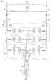
- FIG. 3 is a block diagram for illustrating a configuration of the power conversion device according to the first embodiment.
- FIG. 3 mainly shows the configuration of the power conversion unit 50 in detail.
- power conversion unit 50 includes AC terminal Na and DC terminals Nb and Nc.
- an AC terminal Na is provided for each phase (U, V, W phase) in order to support three-phase AC.
- DC terminals Nb and Nc are electrically connected to power lines 61 and 62 forming DC line 60, respectively.
- Interconnection reactor 57 can be connected between each of DC terminals Nb and Nc and each of power lines 61 and 62.
- the AC terminal Na of each phase is electrically connected to each phase (U, V, W phase) of the AC system 10a.
- the AC terminal Na and the AC system 10 a are electrically connected via an AC circuit breaker 45 and a transformer (three-phase) 56.
- a reactor for interconnection instead of the transformer 56, or it is possible to connect both in combination.
- “electrically connected” indicates a connection state in which electrical energy can be transmitted by direct connection or connection via other elements.
- the power conversion unit 50 further includes a leg circuit 55 corresponding to each phase of the AC system 10a.
- a leg circuit 55 corresponding to each phase of the AC system 10a.
- three leg circuits 55 are arranged to cope with three-phase alternating current. Since the configuration of the leg circuit 55 of each phase is the same, the configuration of the U-phase leg circuit 55 will be described with reference to FIG.
- the leg circuit 55 includes a positive arm 52p connected in series between the DC terminal Nb and the AC terminal Na, and a negative arm 52n connected between the AC terminal Na and the DC terminal Nc.
- Each of the positive side arm 52p and the negative side arm 52n has a plurality of converter cells 51 (hereinafter also simply referred to as “cells”) connected in series. Further, it is possible to connect a reactor in series with the plurality of cells 51.
- each phase leg circuit 55 of each phase is connected in parallel between the power lines 61 and 62. Further, each phase leg circuit 55 has a connection point with an AC terminal Na connected to a corresponding phase of the AC system 10a. Each leg circuit 55 is provided with a current detector 54c for detecting a passing current (arm current Iarm) of the positive arm 52p and the negative arm 52n.
- a current detector 54b for detecting the current (alternating current Iac) flowing between the AC system 10 can be arranged corresponding to the AC terminal Na of each phase.
- a current detector 54a for detecting a current (DC current Idc) flowing between the DC lines 60 can be arranged.
- the direct current Idc and the alternating current Iac can be obtained by calculation using the arm current Iarm. Therefore, the arrangement of the current detectors 54a and 54b can be omitted depending on the arrangement of the current detector 54c. is there. That is, in the present embodiment, DC current Idc and AC current Iac may be directly measured by a current detector or may be obtained by calculation.
- a voltage detector 58a for detecting a DC voltage Vdc between the DC terminals Nb and Nc is further arranged.
- the DC voltage Vdc corresponds to a DC voltage transmitted through the DC line 60.
- Values detected by the current detectors 54b to 54c and the voltage detector 58a are input to the terminal control device 40 (FIG. 2).
- FIG. 3 the configuration example in which the connection point between the positive side arm 52p and the negative side arm 52n is the AC terminal Na is illustrated, but the arrangement of the plurality of cells 51 is limited to such a configuration. It is not a thing.
- a positive arm 52p and a negative arm 52n are connected in series and connected to each phase (U, V, W) of the AC system 10a via a transformer 56.
- the plurality of cells 51 in each phase have an electrical connection point with the AC system 10a via the AC circuit breaker 45, and are connected in series between the DC terminals Nb and Nc (that is, the power lines 61 and 62). Connected to.
- the DC terminal Nb corresponds to a “first DC terminal”
- the DC terminal Nc corresponds to a “second DC terminal”.
- the DC voltage Vdc detected by the voltage detector 58a corresponds to the “DC terminal voltage”.
- the direct current Idc and the alternating current Iac can be obtained as detection values by the current detectors 54a and 54b or calculated values from the detection values of the current detector 54c.
- cell 51a according to the first configuration example has a so-called half-bridge configuration. Specifically, the cell 51a has a pair of output terminals T1, T2, a capacitor C1, and semiconductor switching elements SMp1, SMn1.
- the output terminals T1 and T2 are electrically connected to the output terminals T1 and T2, the AC terminal Na, or the DC terminals Nb and Nc of the other cell 51 for the series connection shown in FIG.
- Capacitor C1 is connected between node N3 and output terminal T1, semiconductor switching element SMp1 is connected between output terminal T1 and node N3, and semiconductor switching element SMn1 is connected between output terminals T1 and T2.
- a voltage detector 58b for detecting a voltage between terminals of the capacitor C1 (hereinafter also simply referred to as “capacitor voltage Vcap”) is arranged.
- the capacitor C1 is connected between the output terminals T1 and T2 via the semiconductor switching element SMp1.
- the output voltage between the output terminals T1 and T2 can be set to + Vcap or 0 by turning on and off the semiconductor switching elements SMp1 and SMn1 (switching operation).
- cell 51b according to the second configuration example has a so-called full bridge configuration. Specifically, the cell 51b includes output terminals T1 and T2, a capacitor C1, and semiconductor switching elements SMp1, SMp2, SMn1, and SMn2.
- the capacitor C1 is connected between the nodes N3 and N4.
- a voltage detector 58b is arranged for the capacitor C1.
- the semiconductor switching element SMp1 is connected between the node N3 and the output terminal T1.
- the semiconductor switching element SMp2 is connected between the node N3 and the output terminal T2.
- the semiconductor switching element SMn1 is connected between the node N4 and the output terminal T1.
- the semiconductor switching element SMn2 is connected between the node N4 and the output terminal T2.
- the cell 51b can switch the output voltage between the output terminals T1 and T2 between + Vcap, 0, and ⁇ Vcap according to the switching operation of the semiconductor switching elements SMp1, SMp2, SMn1, and SMn2.
- cell 51c according to the third configuration example has diode switching diode SM1 connected to semiconductor switching element SMp2 connected between node N3 and output terminal T2, as compared with cell 51b shown in FIG. It differs in that it is replaced.
- the diode D1 is connected with the current direction from the output terminal T2 to the node N3 as the forward direction.
- the structure of the other part of the cell 51c is the same as that of the cell 51b.
- the output voltage of the cell 51c can be + Vcap or 0 depending on the switching operation of the semiconductor switching elements SMp1 and SMn1. Further, when the current flows in the direction toward the output terminal T2 or the output terminal T1, the cell 51c outputs ⁇ Vcap between the output terminals T1 and T2 by turning off the semiconductor switching elements SMp1 and SMn2. be able to.
- cell 51d according to the fourth configuration example has a so-called double clamp cell configuration.
- the cell 51d includes output terminals T1 and T2, capacitors C1 and C2, semiconductor switching elements SMp1, SMp2, SMp3, SMn1, and SMn2, and diodes D1 and D2.
- the capacitor C1 is connected between the nodes N3 and N4.
- the semiconductor switching element SMp1 is connected between the output terminal T1 and the node N3.
- the semiconductor switching element SMn1 is connected between the output terminal T1 and the node N4.
- Semiconductor switching element SMp3 is connected between nodes N6 and N3.
- Diode D1 is connected between nodes N3 and N5 with the current direction from node N3 to N5 as the forward direction.
- the capacitor C2 is connected between the nodes N5 and N6.
- the semiconductor switching element SMp2 is connected between the node N5 and the output terminal T2.
- the semiconductor switching element SMn2 is connected between the node N6 and the output terminal T2.
- Diode D2 is connected between nodes N4 and N6 with the current direction from node N4 to N6 as the forward direction.
- voltage detector 58b is arranged corresponding to both capacitors C1 and C2.
- the cell 51d has Vcap (1), Vcap (2), -Vcap (1), -Vcap (2) between the output terminals T1 and T2 by the switching operation of the semiconductor switching elements SMp1, SMp2, SMp3, SMn1, and SMn2. Or 0 (zero voltage) can be output.
- Capacitor voltages Vcap (1) and Vcap (2) are voltages between terminals of capacitors C1 and C2. However, in the following, when it is not necessary to distinguish between the capacitor voltages Vcap (1) and Vcap (2), these are also collectively referred to as the capacitor voltage Vcap.
- the cell 51d is turned off between the output terminals T1 and T2 by turning off the semiconductor switching elements SMp1 and SMn2 (Vcap (1 ) + Vcap (2)) can be output.
- each of the semiconductor switching elements SMp1, SMp2, SMp3, SMn1, and SMn2 is an arbitrary self such as an IGBT (Insulated Gate Bipolar Transistor), a GCT (Gate Commutated Turn-off) thyristor.
- the arc extinguishing type switching element can be configured by connecting FWD (Freewheeling Diode) in reverse parallel.
- the semiconductor switching element is used as a “switching element” in the converter cell.
- An element for example, a mechanical switch
- the cell 51 shown in FIG. 3 can be configured using any of the cells 51a to 51d shown in FIGS. 4 to 7, the capacitors C1 and C2 correspond to an example of the “storage element”.
- the capacitor voltage Vcap detected by the voltage detector 58b corresponds to “the voltage of the storage element”.
- FIG. 8 is a block diagram for explaining a control configuration of the power conversion unit 50 by the terminal control device 40.
- the function of each block shown in FIG. 8 can be realized by software processing and / or hardware processing by the terminal control device 40.
- power conversion control system 200 that constitutes a part of the control function by terminal control device 40 includes capacitor voltage control unit 210, AC current control unit 220, DC voltage control unit 230, and DC current.
- a control unit 240, a control output synthesis unit 245, and a restart control unit 250 are included.
- the capacitor voltage control unit 210 is based on the detection value by the voltage detector 58b arranged in each cell 51, and the capacitor voltage Vcap (Vcap (1), Vcap (2) of the capacitor C1 (C1 and C2) in each cell 51. )) Is executed to charge and discharge so as to follow the capacitor voltage command value Vcap * to generate a voltage balance control command kbal and an alternating current command value Iac *.
- Capacitor voltage control unit 210 In the power conversion unit 50, the capacitor voltage Vcap in each cell 51 changes according to the balance of power transmission / reception between the AC system 10a and the DC line 60.
- Capacitor voltage control unit 210 generates AC current command value Iac * of AC current Iac so as to generate a charge / discharge current for making the average value of detected capacitor voltage Vcap coincide with capacitor voltage command value Vcap *. To do.
- the alternating current control unit 220 converts the alternating current Iac flowing into or out of the alternating current terminal Na, obtained from the current detector 54b (FIG. 3) or calculation, into an alternating current command value Iac * from the capacitor voltage control unit 210. Is executed to generate an alternating current control command kiac.
- the DC current control unit 240 executes a control calculation for causing the DC current Idc acquired by the current detector 54a or calculation to follow the DC current command value Idc *, and generates a DC current control command kidc.
- the DC voltage control unit 230 executes a control calculation for causing the DC voltage Vdc detected by the voltage detector 58a to follow the DC voltage command value Vdc *, and generates a DC voltage control command kvdc.
- Each of DC current command value Idc *, DC voltage command value Vdc *, and capacitor voltage command value Vcap * may be input from a host controller (not shown) or may be determined in advance by each terminal control device 40.
- a GATEon signal for controlling on / off of each control operation is input to the capacitor voltage control unit 210, the AC current control unit 220, the DC voltage control unit 230, and the DC current control unit 240.
- each power conversion device 30 only one of the DC voltage control unit 230 and the DC current control unit 240 is turned on and the other is turned off.
- DC voltage control unit 230 is turned off, and DC voltage control command kvdc is fixed.
- the control output combining unit 245 includes an AC control command kac from the AC current control unit 220, a DC voltage control command kvdc from the DC voltage control unit 230, a DC current control command kidc from the DC current control unit 240, and a capacitor voltage.
- the output voltage command for controlling the power conversion unit 50 is generated by combining the voltage balance control command kbal from the control unit 210.
- This output voltage command indicates an AC voltage waveform that the positive arm 52p and the negative arm 52n should generate between the AC terminal Na and the DC terminals Nb and Nc in each phase.
- a gate control signal (not shown) for controlling on / off of each semiconductor switching element for controlling the output voltage from each cell 51 is generated in accordance with the output voltage command from the control output synthesizer 245.
- the gate control signal can be generated from an output voltage command indicating an AC voltage waveform by applying pulse width modulation (PWM) control.
- PWM pulse width modulation
- the power conversion device 30a current control
- the power conversion device 30b voltage control
- the power conversion device 30b can control the DC voltage Vdc of the DC line 60 according to the DC voltage command value Vdc * while causing the capacitor voltage Vcap to follow the capacitor voltage command value Vcap *.
- the restart control unit 250 executes the stop control corresponding to the detection of the accident on the DC line 60 and the restart control after the stop for the power converter 30.
- the restart control unit 250 of the power conversion device 30a performs stop control of the power conversion device 30a based on the DC voltage Vdc, the DC current Idc, the AC current Iac, and the capacitor voltage Vcap of the power conversion device 30a.
- Execute restart control Similarly, restart control unit 250 of power conversion device 30b performs stop control and restart of power conversion device 30b based on DC voltage Vdc, DC current Idc, AC current Iac, and capacitor voltage Vcap of power conversion device 30b. Execute control. That is, the restart control unit 250 of each power conversion device 30 operates independently of each other.
- Power conversion device 30 differs in operation in restart control depending on whether voltage control or current control is performed.
- FIG. 9 is a flowchart for explaining the control process of the restart control unit in the power conversion device 30b in charge of voltage control.
- the terminal control device 40 executes the control process shown in FIG. 9, the function of the restart control unit 250 shown in FIG. 8 is realized in the power conversion device 30b.
- terminal control device 40 acquires the voltage and current of power conversion device 30b in order to detect the occurrence of an accident in DC line 60 in step S110.
- the DC voltage Vdc, the DC current Idc, the arm current Iarm, and the AC current Iac are acquired as detection values of the voltage detector 58a and the current detectors 54a to 54c, or calculated values based on the detection values.
- the terminal control device 40 confirms whether or not a stop command has been generated from the host controller in step S120, and in step S130, uses the voltage and / or current acquired in step S110, in the DC line 60. Determine whether an accident has occurred.
- step S130 the occurrence of an accident is detected when an overcurrent occurs in which the direct current Idc exceeds a predetermined reference value It.
- step S130 it is also possible to detect the occurrence of an accident when the DC voltage Vdc is substantially 0 and the DC current Idc exceeds the reference value It. If the occurrence of an accident is detected, step S130 is determined as YES. Alternatively, the occurrence of an accident can be detected also when the alternating current Iac exceeds a predetermined reference value.
- the terminal control device 40 advances the process to steps S140 and S145 when at least one of steps S120 and S130 is determined to be YES.
- step S140 a gate block signal is generated for the power conversion unit 50.
- the power conversion unit 50 is in a state (gate block state) in which each semiconductor switching element of all the cells 51 is fixed off.
- the power conversion unit 50 can execute the processes of steps S130 and S140 so that the gate block state is set when an overcurrent occurs in the DC line 60 (Idc> It).
- step S145 an opening command for the AC circuit breaker 45 is generated.
- the AC circuit breaker 45 can execute the processes of steps S130 and S145 so as to be opened when the direct current or the alternating current exceeds a reference value.
- the power conversion device 30b transits from the operation state to the stop state by the processing of these steps S140 and S145. Note that the processes of steps S140 and S145 may be performed in parallel.
- the stopped state in each cell 51, charging / discharging of the capacitor C1 (and C2) is stopped, and the output voltage becomes zero.
- steps S120 and S130 are NO, that is, during normal operation, the processes of steps S110 to S130 are repeatedly executed at a predetermined cycle.
- the terminal control device 40 responds to the generation of a stop command from the host controller or the occurrence of an accident in the DC line 60 during the operation of the power conversion device 30b by the control processing in steps S110 to S145. Stop control for putting the power conversion device 30b into a stop state can be executed.
- the terminal control device 40 confirms whether or not the start command from the host controller is generated in step S147 in the stop state of the power conversion device 30b.
- the process in step S147 is paired with step S120.
- the stop command is canceled (that is, the start command is generated).
- the power converter device 30b is brought into a stopped state in accordance with the accident detection (YES determination in S130)
- the generation of the start command by the host controller is maintained, so that the determination in step S147 is YES.
- the terminal control device 40 executes the restart control by the processing after Step S150.
- the terminal control device 40 acquires at least the DC voltage Vdc.
- step S160 the terminal control device 40 uses the voltage (and current) acquired in step S150 to determine whether or not the DC line 60 accident has been removed. Most simply, when the DC voltage Vdc, which has been reduced to almost 0 due to the occurrence of a short circuit accident, becomes higher than the reference voltage Vt1, it is determined that the soundness of the DC line 60 has been secured by removing the accident, and step S160 Can be determined as YES.
- the reference voltage Vt1 can be set to have a margin with respect to the lower limit value of the normal voltage range in which the DC line 60 is charged when the short circuit accident is removed.
- step S160 can be determined to be YES when Vdc> Vt1 and Idc ⁇ It (that is, the extinction of overcurrent) by a combination of DC voltage Vdc and DC current Idc.
- the reference voltage Vt1 corresponds to the “first reference voltage”.
- the terminal control device 40 repeatedly executes the processes in steps S150 and S160 at a predetermined cycle while the accident on the DC line 60 is not removed (NO in S160). That is, during the stop state, it is repeatedly determined whether or not the sound quality of the DC line 60 is ensured and the apparatus can be restarted.
- the terminal control device 40 proceeds to step S170 and generates a command for closing the AC circuit breaker 45 again. Thereby, the “restart operation” is started, and the AC power from the AC system 10 a is supplied to the power conversion unit 50. In each leg circuit 55, charging of the capacitor C1 (and C2) of each cell 51 by the AC power from the AC system 10b is started.
- step S185 a deblocking determination is performed to determine whether or not the gate block state of the power conversion unit 50 can be released due to the completion of capacitor charging.
- the deblocking determination can be performed by comparing the reference voltage Vct with the capacitor voltage Vc for charge level evaluation in the whole of the plurality of cells 51 based on the capacitor voltage Vcap detected in step S185.
- the reference voltage Vct can be set so that the power conversion unit 50 has a margin with respect to the minimum value of the capacitor voltage at which rated operation for voltage control can be started.
- the capacitor voltage Vc an average value or a minimum value of the capacitor voltages Vcap of all the cells 51 or a value obtained by arithmetic operation or statistical processing can be appropriately used.
- step S185 is YES and advances the process to step S190.
- step S185 is NO, the processes of steps S180 and S185 are repeatedly executed at a predetermined cycle.
- the terminal control device 40 ends the generation of the gate block signal for the power conversion unit 50 in step S190.
- the power conversion unit 50 will be in the state (gate deblocking state) in which each semiconductor switching element of all the cells 51 was released from being fixed off. Accordingly, each cell 51 can be turned on / off (switching operation) in accordance with a gate control signal generated from the output voltage command from the control output combining unit 245 shown in FIG.
- step S200 terminal control device 40 starts operation of power conversion device 30b, and performs voltage control by power conversion control system 200 shown in FIG. 8, that is, a DC voltage in accordance with DC voltage command value Vdc *. Control of the DC voltage Vdc of the line 60 is started. Thereby, the restart control is terminated, and the normal operation by the AC / DC power conversion between the AC system 10b and the DC line 60 is started. During normal operation, stop control in steps S110 to S145 is performed, which involves monitoring voltage and / or current.
- the power conversion device 30b in charge of voltage control can shift the power conversion device 30b to a stop state in response to the occurrence of an accident in the DC line 60. Furthermore, when the soundness of the DC line 60 is restored after the transition to the stop state, the restarting operation can be autonomously advanced without considering the situation of the other power conversion device (30b).
- FIG. 10 is a flowchart for explaining the control process of the restart control unit in the power conversion device 30a that executes current control.
- the terminal control device 40 executes the control processing shown in FIG. 9, the function of the restart control unit 250 shown in FIG. 8 is realized in the power conversion device 30a.
- terminal control device 40 executes stop control in steps S210 to S245 similar to steps S110 to S145.
- steps S240 and S245 the power conversion device 30a transitions from the operating state to the stopped state. Thereby, even during operation of the power conversion device 30a, the power conversion device 30a can be stopped in response to the generation of a stop command from the host controller or the occurrence of an accident in the DC line 60.
- the terminal control device 40 performs the restart control by the processing after step S250 after confirming the start command from the host controller in step S247 similar to step S147 (FIG. 9). Execute. When the soundness of the DC line 60 is ensured by steps S250 to S270 similar to steps S150 to S170 (when YES is determined in S260), the terminal control device 40 may close the AC circuit breaker 45 again. Yes (S270).
- the terminal control device 40 closes the AC circuit breaker 45 in accordance with ensuring the soundness of the DC line 60, and then re-operates the power conversion device 30b in charge of voltage control without communication through steps S310 to S330. A process for estimating the activation status is executed.
- the terminal control device 40 executes restart determination of the power conversion device 30b in charge of voltage control in step S320.
- step S320 is determined as YES, and the process proceeds to step S330.
- the processes in steps S310 and S320 are performed until the voltage of the DC line 60 rises due to the restart of the power conversion device 30b. It is repeatedly executed at a predetermined cycle.
- the reference voltage Vt2 has a margin with respect to the lower limit value of the normal voltage range of the DC voltage of the DC line 60 when the power conversion device 30 in charge of voltage control described in FIG. 9 is performing the rated operation. Can be set.
- the reference voltage Vt2 corresponds to the “second reference voltage”.
- the terminal control device 40 releases the gate block of the power conversion unit 50 in step S330.
- the off-fixing of the semiconductor switching elements of all the cells 51 is released (gate deblocked state).
- each cell 51 becomes a state in which the on / off operation (switching operation) of each semiconductor switching element is possible.
- the stopped state of the power conversion device 30a is released by the processes of steps S270 and S330.
- the terminal control device 40 allows the power conversion device 30a to control the current of the DC line 60, that is, for power flow, based on the charge state of the capacitor C1 (and C2) of each cell 51. A determination is made as to whether or not the operation can be started. As described above, the charging of the capacitor C1 (and C2) in each cell 51 is started from the time (S270) when the AC circuit breaker 45 is closed.
- step S280 similarly to step S180, the capacitor voltage Vcap is detected by the voltage detector 58b. Further, the operation start possibility determination in step S285 is executed by comparing the capacitor voltage Vc for evaluating the charge level in the plurality of cells 51 and the reference voltage Vct, similarly to the deblocking determination in step S185. Can do.
- step S285 is determined as YES, and the process proceeds to step S300.
- step S285 the terminal control device 40 repeatedly executes the processes in steps S280 and S285 at a predetermined cycle while executing the protective charging control in step S290.
- step S300 the terminal control device 40 starts operation of the power conversion device 30a and performs current control by the power conversion control system 200 shown in FIG. 8, that is, the DC line 60 according to the DC current command value Idc *. Control of the direct current Idc is started. Thereby, restart control is complete
- the DC line 60 is required before the power conversion device in charge of voltage control starts the rated operation without requiring information exchange (that is, communication) between the plurality of power conversion devices 30 (between 30a and 30b).
- the current control is started, the operation of the DC power transmission system 100 can be prevented from becoming unstable. As a result, the restart from the stopped state can be performed quickly and stably.
- Embodiment 2 a modification of the configuration of the power conversion device and control processing of the restart control unit of the power conversion device that executes current control in the configuration will be described.
- FIG. 11 is a circuit diagram illustrating a configuration of the power conversion device according to the second embodiment.
- the power conversion device according to the second embodiment has a current limiting circuit 70 arranged between AC circuit breaker 45 and AC terminal Na, as compared with the configuration of the first embodiment (FIG. 3). It differs in that it further comprises.
- the current limiting circuit 70 includes a current limiting resistor 71 connected between the AC system 10b and the AC terminal Na and a bypass switch 72 for forming a current path that bypasses the current limiting resistor 71 when the AC circuit breaker 45 is closed.
- the on / off of the bypass switch 72 can be controlled by the terminal control device 40 shown in FIG.
- the bypass switch 72 When the bypass switch 72 is off, an alternating current flows between the AC system 10a and the power conversion unit 50 (AC terminal Na) via the current limiting resistor 71.
- the bypass switch 72 when the bypass switch 72 is turned on, an alternating current flows between the AC system 10a and the power conversion unit 50 (AC terminal Na) without passing through the current limiting resistor 71.
- the current limiting circuit 70 can also be arranged on the AC system 10a side with respect to the AC circuit breaker 45.
- FIG. 12 is a flowchart illustrating a control process of the restart control unit in the power conversion device according to the second embodiment.
- FIG. 12 shows a control process in the power conversion apparatus that executes current control.
- the terminal control device 40 executes stop control by steps S210 to S245 similar to FIG. And if the power converter device 30a will be in a stop state, the terminal control apparatus 40 will perform the restart control by the process after step S250, after confirming the starting command from the high-order controller by step S247. At this time, the bypass switch 72 is continuously turned on from the normal operation.
- the terminal control device 40 executes the capacitor discharge determination based on the capacitor voltage Vcap detected by the voltage detector 58b in step S410. For example, when the same capacitor voltage Vc as in step S285 is lower than the reference voltage Vdt (Vc ⁇ Vdt), the terminal control device 40 determines that the capacitor C1 (and C2) is discharged (S410). YES determination), the process can proceed to step S420. In step S420, the bypass switch 72 is turned off. On the other hand, when the capacitor voltage Vc is equal to or higher than the reference voltage Vdt, the terminal control device 40 determines that step S410 is NO and skips step S320. Thereby, the bypass switch 72 is kept on.
- the bypass switch 72 includes the capacitor C1 (and C2) is turned on or off according to the degree of discharge. For this reason, when the AC circuit breaker 45 is closed again, the charging current of the low-voltage capacitor C1 (and C2) having a high discharge degree can be suppressed.
- the reference voltage Vdt can be determined in advance by an actual machine experiment or the like in consideration of the relationship between the capacitor voltage Vcap and the charging current generated when the bypass switch 72 is turned on.
- the terminal control device 40 executes a restart determination of the power conversion device 30b in charge of voltage control through steps S310 and S320 similar to FIG. If it is determined that the power conversion device 30b has already been restarted due to an increase in the DC voltage Vdc (YES in S320), the on / off of the bypass switch 72 is controlled in steps S430 to S460.
- the terminal control device 40 determines whether or not the bypass switch 72 is turned on in step S430. If bypass switch 72 is turned off in step S420 according to the capacitor discharge determination, step S430 is determined as NO, and the process proceeds to steps S440 to S460.
- the terminal control device 40 acquires the capacitor voltage Vcap at step S440, and executes capacitor initial charge determination at step S450. For example, as in step S410, the capacitor initial charge determination can be executed based on a comparison between the capacitor voltage Vc and the reference voltage Vich.
- step S460 the bypass switch 72 is turned on in response to the completion of the initial charging. While the capacitor voltage Vc is lower than the reference voltage Vich (when NO is determined in S450), the capacitor C1 (and C2) continues to be charged while the bypass switch 72 is kept off, and step S440 and The determination in S450 is repeatedly executed at a predetermined cycle.
- step S430 is determined as YES, so the processing of steps S440 to S460 is skipped.
- the terminal control device 40 releases the gate block of the power conversion unit 50 in step S330 with the bypass switch 72 turned on. Further, the terminal control device 40 executes steps S280 to S300 similar to those in FIG. 10, and thus, when the charging of the capacitor C1 (and C2) of each cell 51 is completed by the power conversion unit 50 gate-deblocked, The operation (current control) of the power conversion device 30a is started.
- the reference voltage Vich in the capacitor initial charge determination is set to be equal to or higher than the reference voltage Vdt in the capacitor discharge determination.
- the reference voltage Vct in the operation start determination (S320) is set higher than the reference voltage Vich and the reference voltage Vdt (Vct> Vich ⁇ Vdt).
- the capacitor voltage Vc may be obtained by different arithmetic processing.
- the average value of the capacitor voltages Vcap of the plurality of cells 51 can be set as the capacitor voltage Vc
- the minimum value of the capacitor voltages Vcap of the plurality of cells 51 can be set as the capacitor voltage Vc.
- the capacitors C1 (and C2) in the power conversion unit 50 (each cell 51) during the stop state. ) Can be restarted without causing an excessive inrush current even when the battery is discharged.
- FIG. 13 is a block diagram illustrating a configuration of the power conversion device according to the third embodiment.
- the accident current bypass unit 59 is configured to have a current path for returning the short-circuit current flowing into the power conversion unit 50 by bypassing the plurality of cells 51 in each leg circuit 55.
- the fault current bypass unit 59 may be configured with a diode connected in reverse parallel to the plurality of converter cells 51 with the forward direction being the current direction from the AC terminal Na to the DC terminal Nb in the positive arm 52p. it can.
- the fault current bypass unit 59 is configured by a diode connected in reverse parallel to the plurality of converter cells 51 with the current direction from the DC terminal Nc to the AC terminal Na as the forward direction. Can do. Note that these diodes are reverse-biased by the potential difference between the DC terminals Nb and Nc (power lines 61 and 62) and the AC terminal Na during normal times (when no accident occurs), so that no current path is formed. .
- the fault current bypass unit 59 can be configured by a semiconductor switching element such as a semiconductor relay (not shown), an electromagnetic relay, a mechanical switch, or a thyristor whose ON / OFF is controlled by the terminal control device 40. .
- the accident current bypass unit 59 cuts off the current path for returning the short-circuit current by default, but forms it when an accident occurs in the DC line 60. To be controlled.
- the fault current bypass unit 59 that can be configured as described above can be arranged corresponding to each cell 51. That is, as long as a path for bypassing the plurality of cells 51 and returning the short-circuit current flowing into the power conversion unit 50 can be ensured between the DC terminals Nc and Nb, the arrangement mode of the accident current bypass unit 59 is arbitrary.
- FIG. 15 is a flowchart illustrating control processing of stop control and restart control in the power conversion device according to the third embodiment.
- terminal control device 40 issues a command for forming an accident current bypass path to fault current bypass unit 59 in step S510.
- Output in addition, the process by step S510 can be performed in parallel with step S240 and step S245 according to YES determination of step S220 or S230.
- the terminal control device 40 confirms the start command from the host controller in step S247 in a state where the fault current path that bypasses the plurality of cells 51 is formed, and then performs steps S250 to S260 similar to FIG. Perform soundness judgment. Then, when the soundness of the DC line 60 is ensured by removing the accident (when YES is determined in S260), the terminal control device 40 issues a command for interrupting the accident current bypass path in step S520. Output for.
- the terminal control device 40 executes the restart control after step S270 similar to FIG. 10 in a state where the current path by the accident current bypass unit 59 is interrupted. Thereby, the same restart control as that of the first embodiment is realized.
- the power conversion device in addition to the effect of the power conversion device according to the first embodiment, even if an accident current flows into the power conversion unit 50, the plurality of cells 51 are bypassed. By forming the current path, device failure can be suppressed.
- FIG. 16 is a block diagram for illustrating a configuration of a power conversion device according to the fourth embodiment.
- the power conversion device according to the fourth embodiment is provided between DC terminal Nb and power line 61 and between DC terminal Nc and power line 62 as compared with the configuration according to the first embodiment (FIG. 3). It is different in that a DC circuit breaker 80 is provided between them. Further, the voltage detector 58a is arranged to detect the DC voltage Vdc on the DC line 60 side of the DC circuit breaker 80.
- the configuration of the other parts in FIG. 16 is the same as that in FIG. 3, so detailed description will not be repeated.
- the opening / closing of the DC circuit breaker 80 is controlled by the terminal control device 40.
- the terminal control device 40 opens the DC breaker 80, the power conversion unit 50 can be disconnected from the DC line 60. Therefore, by opening the DC breaker 80, the current flowing between the AC system 10a and the DC line 60 via the power conversion unit 50 can be blocked. That is, the DC circuit breaker 80 also corresponds to an example of a “current circuit breaker”. In the configuration example of FIG. 16, the power conversion unit 50 can be disconnected from both the AC system 10 a and the DC line 60 by the AC circuit breaker 45 and the DC circuit breaker 80.
- FIG. 17 is a flowchart illustrating a first example of control processing of the restart control unit in the power conversion device according to the fourth embodiment.
- terminal control device 40 opens DC circuit breaker 80 in step S610 in addition to the stop control in steps S210 to S245 similar to FIG.
- the process by step S610 can be performed in parallel with step S240 (gate block of the power conversion unit 50) and S245 (opening of the AC circuit breaker 45) according to YES determination of step S220 or S230.
- the terminal control device 40 performs the soundness determination of the DC line 60 through steps S250 to S260 similar to FIG. 10 after confirming the start command from the host controller in step S247 with the DC circuit breaker 80 opened. . Then, when the soundness of the DC line 60 is ensured by removing the accident (when YES is determined in S260), the terminal control device 40 closes the DC breaker 80 again in step S620. In addition, the process of step S620 can be performed in parallel with step S270 (reclosing circuit of the AC circuit breaker 45) according to the YES determination of step S260.
- the terminal control device 40 executes the restart control after step S270 as in FIG. 10 in a state where the DC circuit breaker 80 is closed. Thereby, the same restart control as that of the first embodiment is realized. Further, the power conversion unit 50 can be quickly disconnected from the path of the accident current by opening the DC circuit breaker 80 according to the accident detection.
- FIG. 18 is a flowchart illustrating a second example of the control process of the restart control unit in the power conversion device according to the fourth embodiment.
- FIG. 18 is compared with FIG. 17, and in the control process according to the second example, the timing at which the DC circuit breaker 80 once opened is closed again is different from the first example (FIG. 17).
- step S610 the process until the DC circuit breaker 80 is opened in step S610 is the same as that in FIG.
- the power conversion device 30a can proceed with the start-up process regardless of the soundness of the DC line 60. Therefore, after confirming the activation command from the host controller in step S247, the same steps S270 (reclosing circuit of the AC circuit breaker 45) and S330 (releasing the gate block of the power conversion unit 50) similar to FIG. 10 may be executed. it can.
- the terminal control device 40 performs the capacitor charging of each cell 51 in S280 to S290 while maintaining the state where the DC circuit breaker 80 is opened.
- steps S310 and S320 are performed. Then, it is determined whether or not the DC line 60 has been raised by the rated operation of the power conversion device 30 in charge of voltage control.
- the terminal control device 40 is stepped.
- the DC circuit breaker 80 is closed again.
- the operation of the power converter 30a is started in step S300, and the control of the DC current Idc of the DC line 60 according to the DC current command value Idc * is started. Accordingly, normal operation is started, and a power flow is generated between the AC system 10a and the DC line 60 by AC / DC power conversion.
- an accident current generated in the DC line 60 can be quickly cut off. Thereby, the apparatus failure in the power conversion unit 50 by inflow of accident current can be suppressed.
- the restart operation (capacitor charging of each cell 51) in the power conversion device 30a is advanced regardless of the state of the DC line 60. Therefore, the effect of speeding up the restarting operation is further generated.
- the arrangement of the AC circuit breaker 45 may be omitted, and only the DC circuit breaker 80 may be arranged as a “current circuit breaker”.
- the effect of the power conversion device according to the fourth embodiment can be obtained by the control processing in which steps S245 and S275 are deleted in FIGS. 17 and 18.
- FIG. 19 is a block diagram illustrating a configuration of a DC power transmission system according to the fifth embodiment.
- DC power transmission system 100 # in DC power transmission system 100 # according to the fifth embodiment, a plurality of AC systems 10a to 10c and power conversion devices 30a to 30c are connected via DC circuit breakers 64a to 64c.
- the power conversion device 30a performs bidirectional AC / DC power conversion between the AC system 10a and the DC line 60a composed of the power lines 61a and 62a.
- the power conversion device 30b performs bidirectional AC / DC power conversion between the AC system 10b and the DC line 60b configured by the power lines 61b and 62b.
- the power conversion device 30c performs bidirectional AC / DC power conversion between the AC system 10c and the DC line 60c configured by the power lines 61c and 62c.
- the DC lines 60a to 60c are connected to common power lines 65a and 65b via the DC circuit breakers 64a to 64c.
- FIG. 19 shows a control device 20 for controlling the overall operation of DC power transmission system 100 #.
- the control device 20 can be configured to execute predetermined software processing and / or hardware processing by a microcomputer or the like.
- the control device 20 has a function corresponding to the host controller described in the first to fifth embodiments.
- the opening / closing of the DC circuit breakers 64a to 64c is basically controlled by the control device 20. Or you may give the function which opens and closes the DC circuit breaker connected to a corresponding DC track
- FIG. For example, regarding the opening / closing of the DC circuit breaker 64a, in addition to the control device 20, the terminal control device 40 of the power conversion device 30a detects an accident by the terminal control device 40 (S230) or a command from the control device 20 (S220). It is also possible to configure so as to open according to the above.
- the DC circuit breakers 64a to 64c constitute a line switch 650 for switching the DC lines 60a to 60c interconnected via the common power lines 65a and 65b, that is, the AC systems 10a to 10c to be connected. can do.
- the DC circuit breakers 64a to 64c are closed.
- one of the power conversion devices 30a to 30c operates as a power conversion device in charge of voltage control according to a command from the control device 20. And the remaining power converter devices 30 perform electric current control.
- any one of the DC lines 60a to 60c is not a temporary accident caused by a lightning strike, but a continuous accident (hereinafter referred to as “recovery work”) caused by deterioration of a cable or a line.
- the control device 20 controls the line switch 650 so that the power system related to the permanent failure is disconnected from the other power systems.
- the DC line 60 in which a permanent failure has occurred is disconnected from the power lines 65a and 65b, so that the DC power transmission can be resumed using the remaining normal power system.
- each power conversion device 30 can be restarted quickly.
- FIG. 20 is a flowchart illustrating a control process when an accident occurs in the DC power transmission system according to the fifth embodiment.
- the control process shown in FIG. 20 can be executed by control device 20 for controlling the overall operation of DC power transmission system 100 #.
- control device 20 determines whether the accident is due to the occurrence of a permanent failure in step S700. Determine whether.
- the control device 20 can detect the occurrence of an accident on the DC line 60 independently of the power conversion devices 30a to 30c. Note that a known technique can be appropriately used as the determination method in step S700.
- the control device 20 When a permanent failure has occurred (when YES is determined in S710), the control device 20 replaces the DC line (any one of the DC lines 60a to 60c) of the power system in which the permanent failure has occurred with the power line 65a in step S720. , 65b and a control command for the line switch 650 are generated so as to be disconnected from the DC lines of other power systems.
- control device 20 determines whether or not a permanent failure has occurred in the power system including the power conversion device 30 in charge of voltage control in step S730. That is, if a permanent failure occurs in the power system including the power conversion device 30 that executes current control, S730 is determined as NO.
- step S730 When the determination in step S730 is YES, the control device 20 newly designates one of the electric power systems in which no permanent failure has occurred as the person in charge of voltage control in step S740. Thereby, the power converter device 30 in charge of voltage control is changed. At this time, the newly designated power conversion device 30 in charge of voltage control executes the restart control according to FIG. 9, and each other power conversion device 30 executes the restart control according to any of the first to fifth embodiments. By doing so, all the power converter devices 30 can be restarted from the stopped state without accompanying information transmission (communication) between the power converter devices 30. As a result, after the permanent failure is disconnected, the interconnection of the AC systems 10a to 10c via the DC line 60 is promptly resumed.
- the control device 20 skips the process of step S720 when NO is determined in step S730, that is, when a permanent failure occurs in the power system in charge of current control. As a result, the power conversion device 30 in charge of voltage control is maintained because it does not need to be changed. Each power conversion device 30 executes restart control without accompanying information exchange (communication) between the power conversion devices 30 according to any of the first to fifth embodiments.
- control device 20 determines the state of line switch 650 (all DC breakers 64a to 64c are closed) and power conversion devices 30a to 30a. Since it is not necessary to change the charge of voltage control between 30c, the process of steps S710 to S740 is skipped and the process is terminated.
- Each power conversion device 30 can be restarted according to any one of the first to fifth embodiments without transmitting / receiving information to / from other power conversion devices 30.
- the permanent failure may occur.
- the separation of the generated power system and the restart of the interconnection operation with the remaining healthy power system can be realized by the stable and quick restart of the power conversion device 30.
- a DC power transmission system in which two power conversion devices 30 are arranged corresponding to two AC systems is illustrated for the sake of simplicity. Even in a configuration in which three or more power conversion devices 30 are arranged corresponding to the AC system, one of the power conversion devices 30 is in charge of voltage control, and current control is performed in each of the remaining power conversion devices 30. By executing, the same control can be performed.
Abstract
This DC power transmission system (60) connects a plurality of AC systems (10a, 10b) via a DC line (60). A plurality of electric power conversion apparatuses (30a, 30b) are connected between the plurality of AC systems (10a, 10b) and the DC line (60). One of the plurality of electric power conversion apparatuses (30a, 30b) controls the voltage of the DC line (60), while the remainder control the current input and output to and from the DC line (60). In a restart which restarts electric power conversion to control the DC current of the DC line (60) from a stopped state, the electric power conversion apparatus (30b) which performs current control monitors the voltage of the DC line (60) and initiates the restart operation, without exchange of information with other electric power conversion apparatuses (30b).
Description
この発明は電力変換装置および直流送電システムに関し、より特定的には、直流線路を介して複数の交流系統を連系するための直流送電システムおよび、それに用いられる電力変換装置に関する。
The present invention relates to a power conversion device and a DC power transmission system, and more particularly to a DC power transmission system for connecting a plurality of AC systems via a DC line, and a power conversion device used therefor.
電力の輸送距離が長くなる系統においては、高電圧による直流送電システムがしばしば用いられる。直流送電システムは、複数の交流系統が直流線路を介して接続された構成において、1つの交流系統からの交流電力を順変換器で高電圧の直流電力へと変換して直流線路によって伝送するとともに、直流線路の直流電力を逆変換器で交流電力へと変換して他の交流系統に供給することで、電力を伝送することができる。
In systems where the transport distance of power is long, DC transmission systems with high voltage are often used. In a DC power transmission system, in a configuration in which a plurality of AC systems are connected via a DC line, AC power from one AC system is converted into high voltage DC power by a forward converter and transmitted through the DC line. The power can be transmitted by converting the DC power of the DC line into AC power with an inverse converter and supplying it to another AC system.
直流送電システムに適した電力変換装置の一つとして、モジュラーマルチレベル変換器(以下、MMCとも称する)が用いられている。MMCは、2つの直流端子間に、複数の単位変換器(セル)が、交流端を経由して多段接続されたアームを有する。各セルは、複数の半導体スイッチと直流キャパシタを備えており、その構成は、チョッパ回路またはブリッジ回路など、バリエーションがある。
A modular multilevel converter (hereinafter also referred to as MMC) is used as one of power converters suitable for a DC power transmission system. The MMC has an arm in which a plurality of unit converters (cells) are connected in multiple stages via an AC terminal between two DC terminals. Each cell includes a plurality of semiconductor switches and DC capacitors, and there are variations in the configuration such as a chopper circuit or a bridge circuit.
たとえば、特開2014-180131号公報(特許文献1)には、直流線路に事故が発生した場合の再起動動作において、交流遮断器を開放した状態で、チョッパ回路で構成された変換器セルのキャパシタに蓄積されたエネルギを直流線路に供給する技術が記載されている。これにより、直流線路の電圧を上昇させることによって、電力変換装置を高速に再起動することができる。
For example, Japanese Patent Laid-Open No. 2014-180131 (Patent Document 1) describes a converter cell configured with a chopper circuit in a state where an AC circuit breaker is opened in a restart operation when an accident occurs in a DC line. A technique for supplying energy stored in a capacitor to a DC line is described. Thereby, a power converter device can be restarted at high speed by raising the voltage of a DC track.
直流送電システムでは、直流線路での事故発生時には、複数の交流系統の各々を一旦解列するとともに、直流線路および複数の交流系統の間にそれぞれ接続された複数の電力変換装置を停止する必要がある。
In a DC power transmission system, when an accident occurs in a DC line, it is necessary to temporarily disconnect each of the plurality of AC systems and stop a plurality of power conversion devices connected respectively between the DC line and the plurality of AC systems. is there.
落雷等による一時的な事故の発生時には、当該事故原因が除去されると、複数の電力変換装置を再起動することにより、潮流による電力伝送を再開することができる。しかしながら、その際に各電力変換装置が無秩序に再起動動作を行うと、システムの健全性の回復を十分に確認できないまま電力変換装置が動作を始めることにより、システム全体の動作が不安定になることが懸念される。
When a temporary accident such as a lightning strike occurs, if the cause of the accident is removed, power transmission by power flow can be resumed by restarting a plurality of power conversion devices. However, if each power conversion device performs a disorderly restart operation at that time, the operation of the entire system becomes unstable because the power conversion device starts operating without sufficiently confirming the restoration of the soundness of the system. There is concern.
一方で、複数の電力変換装置間での情報の授受による確認を伴って各電力変換装置を動作させると、通信時間を含む処理時間の増大によって迅速な再起動が妨げられることが懸念される。
On the other hand, if each power conversion device is operated with confirmation by exchanging information among a plurality of power conversion devices, there is a concern that rapid restart may be hindered due to an increase in processing time including communication time.
この発明はこのような問題点を解決するためになされたものであって、その目的は、直流線路を介して複数の交流系統を連系するための直流送電システムに用いられる電力変換装置において、停止状態からの再起動を、他の電力変換装置との情報の授受を要することなく迅速かつ安定的に行うことである。
This invention was made in order to solve such a problem, and its purpose is in a power converter used in a DC power transmission system for connecting a plurality of AC systems via a DC line. Restarting from a stopped state is to be performed quickly and stably without requiring information exchange with other power conversion devices.
本開示に係る電力変換装置は、直流線路を介して複数の交流系統を連系するための直流送電システムに用いられる電力変換装置であって、電力変換ユニットと、電流遮断器と、端子制御装置とを備える。電力変換ユニットは、複数の交流系統のうちの1つの交流系統と直流線路との間で双方向に交流から直流、または、直流から交流の電力変換(以下、交流/直流電力変換とも称する)を実行するように構成される。電流遮断器は、電力変換ユニットを経由して前記1つの交流系統および前記直流線路の間を流れる電流を遮断するように構成される。端子制御装置は、電流遮断器および電力変換ユニットを制御する。電力変換ユニットは、直流線路と電気的に接続された第1および第2の直流端子と、交流系統と電気的に接続された交流端子と、複数の変換器セルとを含む。複数の変換器セルは、交流端子との電気的な接続点を有するように第1および第2の直流端子間に直列に接続される。各変換器セルの各々は、一対の出力端子間に接続された蓄電素子と、出力端子間に対する蓄電素子の充放電を制御するための複数のスイッチング素子とを有する。複数のスイッチング素子は、出力端子に対する蓄電素子に対して並列または直列に接続される。電力変換装置は、停止状態では、電流遮断器が開放され、かつ、電力変換ユニットが各変換器セルの複数のスイッチング素子がオフに固定されたゲートブロック状態である。端子制御装置は、停止状態から直流線路へ入出力する直流電流を制御するための交流/直流電力変換を開始するための再起動動作において、直流端子電圧および蓄電素子の電圧に応じて、停止状態を解除し、複数の変換器セルでの複数のスイッチング素子のオンオフによる交流/直流電力変換を開始する。
A power converter according to the present disclosure is a power converter used in a DC power transmission system for interconnecting a plurality of AC systems via a DC line, and includes a power conversion unit, a current breaker, and a terminal controller. With. The power conversion unit performs AC to DC or DC to AC power conversion (hereinafter also referred to as AC / DC power conversion) bidirectionally between one AC system and a DC line of a plurality of AC systems. Configured to run. The current breaker is configured to cut off a current flowing between the one AC system and the DC line via the power conversion unit. The terminal control device controls the current breaker and the power conversion unit. The power conversion unit includes first and second DC terminals electrically connected to the DC line, an AC terminal electrically connected to the AC system, and a plurality of converter cells. The plurality of converter cells are connected in series between the first and second DC terminals so as to have an electrical connection point with the AC terminal. Each converter cell has a power storage element connected between a pair of output terminals and a plurality of switching elements for controlling charge / discharge of the power storage element between the output terminals. The plurality of switching elements are connected in parallel or in series with the storage element with respect to the output terminal. In the stop state, the power conversion device is in a gate block state in which the current breaker is opened and the power conversion unit has a plurality of switching elements of each converter cell fixed to OFF. In the restart operation for starting the AC / DC power conversion for controlling the DC current input / output to / from the DC line from the stop state, the terminal control device is in the stop state according to the DC terminal voltage and the voltage of the storage element. And the AC / DC power conversion is started by turning on / off the plurality of switching elements in the plurality of converter cells.
本開示によれば、直流線路を介して複数の交流系統を連系するための直流送電システムに用いられる電力変換装置において、停止状態からの再起動を、他の電力変換装置との通信を要することなく、迅速かつ安定的に行うことができる。
According to the present disclosure, in a power converter used in a DC power transmission system for connecting a plurality of AC systems via a DC line, restart from a stopped state requires communication with another power converter. It can be performed quickly and stably.
以下に、本発明の実施の形態について図面を参照して詳細に説明する。なお、以下では図中の同一または相当部分には同一符号を付してその説明は原則的に繰返さないものとする。
Hereinafter, embodiments of the present invention will be described in detail with reference to the drawings. In the following description, the same or corresponding parts in the drawings are denoted by the same reference numerals, and the description thereof will not be repeated in principle.
実施の形態1.
図1は、本実施の形態に従う電力変換装置が適用される直流送電システムの構成例を説明する概略ブロック図である。Embodiment 1 FIG.
FIG. 1 is a schematic block diagram illustrating a configuration example of a DC power transmission system to which a power conversion device according to the present embodiment is applied.
図1は、本実施の形態に従う電力変換装置が適用される直流送電システムの構成例を説明する概略ブロック図である。
FIG. 1 is a schematic block diagram illustrating a configuration example of a DC power transmission system to which a power conversion device according to the present embodiment is applied.
図1を参照して、直流送電システム100は、直流線路60を介して複数の交流系統10aおよび10bを連系する。直流送電システム100は、直流線路60と、複数の電力変換装置30とを有する。電力変換装置30は、直流送電システム100によって連系される各交流系統10と直流線路60との間にそれぞれ配置される。直流線路60は、高電圧側の直流母線に相当する電力線61と、低電圧側の直流母線に相当する電力線62を有する。
Referring to FIG. 1, a DC power transmission system 100 interconnects a plurality of AC systems 10 a and 10 b through a DC line 60. The DC power transmission system 100 includes a DC line 60 and a plurality of power conversion devices 30. The power converter 30 is disposed between each AC system 10 and the DC line 60 that are interconnected by the DC power transmission system 100. The DC line 60 includes a power line 61 corresponding to a DC bus on the high voltage side and a power line 62 corresponding to a DC bus on the low voltage side.
図1の構成例では、交流系統10aおよび直流線路60の間に電力変換装置30aが配置され、交流系統10bおよび直流線路60の間には、電力変換装置30bが配置される。電力変換装置30aは、交流系統10aおよび直流線路60の間で、双方向の交流/直流電力変換を実行する。同様に、電力変換装置30bは、交流系統10bおよび直流線路60の間で、双方向の交流/直流電力変換を実行する。
1, a power conversion device 30a is disposed between the AC system 10a and the DC line 60, and a power conversion device 30b is disposed between the AC system 10b and the DC line 60. The power conversion device 30 a performs bidirectional AC / DC power conversion between the AC system 10 a and the DC line 60. Similarly, the power conversion device 30b performs bidirectional AC / DC power conversion between the AC system 10b and the DC line 60.
以下では、複数の交流系統10a,10bを包括的に表記する場合には、単に交流系統10と称する。同様に、複数の交流系統10a,10bにそれぞれ対応して配置される電力変換装置30a,30bについても、包括的に表記する場合には単に電力変換装置30と称する。
Hereinafter, when a plurality of AC systems 10a and 10b are comprehensively described, they are simply referred to as an AC system 10. Similarly, power converters 30a and 30b arranged corresponding to a plurality of AC systems 10a and 10b are also simply referred to as power converter 30 when they are comprehensively described.
直流送電システム100において、複数の電力変換装置30は、直流線路60の直流電圧を制御する電力変換装置と、直流線路60および対応の交流系統の間を流れる直流電流(または直流電力)を制御する電力変換装置とに分類される。通常、複数の電力変換装置30のうちの1つが電圧制御を担当し、残りの電力変換装置の各々は電流制御を実行する。
In the DC power transmission system 100, the plurality of power conversion devices 30 controls a DC power (or DC power) flowing between the power conversion device that controls the DC voltage of the DC line 60 and the DC line 60 and the corresponding AC system. It is classified as a power converter. Usually, one of the plurality of power conversion devices 30 is in charge of voltage control, and each of the remaining power conversion devices performs current control.
たとえば、発電側の交流系統と接続された電力変換装置が電圧制御を担当する一方で、その他の電力変換装置は電流制御を実行することができる。ただし、各電力変換装置30が、双方向の交流/直流電力変換を実行可能に構成されている場合には、潮流の方向などに応じて、運転動作中に、電圧制御を担当する電力変換装置30を切換えることができる。たとえば、図示しない上位コントローラからの指示に従って、各電力変換装置30は電圧制御および電流制御のいずれかを選択的に実行することができる。
For example, while the power converter connected to the AC system on the power generation side is in charge of voltage control, other power converters can execute current control. However, when each power conversion device 30 is configured to be able to perform bidirectional AC / DC power conversion, the power conversion device in charge of voltage control during the operation operation according to the direction of power flow or the like. 30 can be switched. For example, each power conversion device 30 can selectively execute either voltage control or current control in accordance with an instruction from a host controller (not shown).
以下では、電力変換装置30bによって直流線路60の直流電圧が制御される一方で、電力変換装置30aは、直流線路60および交流系統10bの間を流れる直流電流(直流電力)を制御するものとする。すなわち、直流送電システムにおいて、電力変換装置30bは、電圧制御を担当する「第1の電力変換装置」の一実施例に対応し、電力変換装置30aは、電流制御を実行する「第2の電力変換装置」の一実施例に対応する。
Hereinafter, while the DC voltage of the DC line 60 is controlled by the power converter 30b, the power converter 30a controls the DC current (DC power) flowing between the DC line 60 and the AC system 10b. . In other words, in the DC power transmission system, the power conversion device 30b corresponds to an example of a “first power conversion device” in charge of voltage control, and the power conversion device 30a performs “second power” for executing current control. This corresponds to an example of the “conversion device”.
図2は、図1に示された電力変換装置の構成を示す概略ブロック図である。なお、以下では、電流制御を実行する電力変換装置30aの構成について主に説明するが、電圧制御を担当する電力変換装置30bについても、電力変換装置30aと同様に構成することが可能である。
FIG. 2 is a schematic block diagram showing the configuration of the power conversion apparatus shown in FIG. In the following, the configuration of the power conversion device 30a that performs current control will be mainly described. However, the power conversion device 30b in charge of voltage control can also be configured in the same manner as the power conversion device 30a.
図2を参照して、電力変換装置30aは、端子制御装置40と、交流電流を遮断するための交流遮断器45と、双方向の交流/直流電力変換を実行する電力変換ユニット50とを有する。電力変換ユニット50は、公知のMMCによって構成することができるが、その詳細な構成例は、後程説明する。
Referring to FIG. 2, power conversion device 30 a includes a terminal control device 40, an AC circuit breaker 45 for cutting off an alternating current, and a power conversion unit 50 that performs bidirectional AC / DC power conversion. . The power conversion unit 50 can be configured by a known MMC, and a detailed configuration example will be described later.
端子制御装置40は、図示しない上位コントローラからの指令や、後に説明する各検出器から入力された検出信号等を用いて、交流遮断器45の開閉および電力変換ユニット50の動作を制御する。端子制御装置40は、たとえばマイクロコンピュータ等で構成することが可能である。一例として、端子制御装置40は、図示しないメモリおよびCPU(Control Processing Unit)を内蔵し、メモリに予め格納されたプログラムをCPUが実行することによるソフトウェア処理によって、以下で説明する制御動作を実行することができる。あるいは、当該制御動作の一部または全部については、ソフトウェア処理に代えて、内蔵された専用の電子回路等を用いたハードウェア処理によって実現することも可能である。
The terminal control device 40 controls the opening / closing of the AC circuit breaker 45 and the operation of the power conversion unit 50 using commands from a host controller (not shown), detection signals input from each detector described later, and the like. The terminal control device 40 can be composed of, for example, a microcomputer. As an example, the terminal control device 40 includes a memory (not shown) and a CPU (Control Processing Unit), and executes a control operation described below by software processing by the CPU executing a program stored in advance in the memory. be able to. Alternatively, part or all of the control operation can be realized by hardware processing using a built-in dedicated electronic circuit or the like instead of software processing.
交流遮断器45は、交流系統10aおよび電力変換ユニット50の間に接続される。交流遮断器45は、端子制御装置40からの指令に応じて開放または閉路される。交流遮断器45を開放することによって、電力変換ユニット50は、交流系統10aから解列される。この結果、電力変換ユニット50を経由した、交流系統10aおよび直流線路60の間を流れる電流を遮断することができる。すなわち、交流遮断器45は「電流遮断器」の一実施例に対応する。
AC breaker 45 is connected between AC system 10a and power conversion unit 50. The AC circuit breaker 45 is opened or closed according to a command from the terminal control device 40. By opening the AC circuit breaker 45, the power conversion unit 50 is disconnected from the AC system 10a. As a result, the current flowing between the AC system 10a and the DC line 60 via the power conversion unit 50 can be cut off. That is, the AC circuit breaker 45 corresponds to an example of a “current circuit breaker”.
各交流系統10は、単相および複数相交流電力のいずれ取り扱うものでもよいが、本明細書では、交流系統10aを含む各交流系統10は、三相交流電力を取り扱うものとする。したがって、交流遮断器45の閉路時において、電力変換ユニット50は、交流系統10aから受電する三相交流電力を直流電力へと変換し直流線路60へ送電する電力変換、または、直流線路60から受電する直流電力を交流電力へと変換して交流系統10bへ送電する電力変換を選択的に実行する。
Each AC system 10 may handle either single-phase or multiple-phase AC power, but in this specification, each AC system 10 including the AC system 10a is assumed to handle three-phase AC power. Therefore, when the AC circuit breaker 45 is closed, the power conversion unit 50 converts the three-phase AC power received from the AC system 10a into DC power and transmits power to the DC line 60, or receives power from the DC line 60. The power conversion for converting the DC power to be converted into AC power and transmitting the AC power to the AC system 10b is selectively executed.
なお、電圧制御を担当する電力変換装置30bは、電流制御を実行する電力変換装置30bと異なる構成を有してもよいが、以下、本明細書では、簡単のため、電力変換装置30aおよび30b、すなわち、各電力変換装置30の構成は同様であるものとする。このようにすると、上述したような、上位コントローラ等からの指示に従った、各電力変換装置30での電圧制御および電流制御の切換えへの対応が容易となる。
The power conversion device 30b in charge of voltage control may have a configuration different from that of the power conversion device 30b that executes current control. However, in the present specification, for the sake of simplicity, the power conversion devices 30a and 30b are hereinafter described. That is, the configuration of each power conversion device 30 is the same. If it does in this way, the response | compatibility to the switching of the voltage control in each power converter device 30 and current control according to the instruction | indication from a high-order controller etc. as mentioned above becomes easy.
次に、電力変換ユニット50の構成を詳細に説明する。
図3は、実施の形態1に従う電力変換装置の構成を説明するためのブロック図である。図3には、主に電力変換ユニット50の構成が詳細に示される。 Next, the configuration of thepower conversion unit 50 will be described in detail.
FIG. 3 is a block diagram for illustrating a configuration of the power conversion device according to the first embodiment. FIG. 3 mainly shows the configuration of thepower conversion unit 50 in detail.
図3は、実施の形態1に従う電力変換装置の構成を説明するためのブロック図である。図3には、主に電力変換ユニット50の構成が詳細に示される。 Next, the configuration of the
FIG. 3 is a block diagram for illustrating a configuration of the power conversion device according to the first embodiment. FIG. 3 mainly shows the configuration of the
図3を参照して、電力変換ユニット50は、交流端子Naと、直流端子NbおよびNcとを備える。図3の例では、三相交流に対応するために、各相(U、V,W相)に交流端子Naが設けられる。直流端子NbおよびNcは、直流線路60を形成する電力線61および62とそれぞれ電気的に接続される。直流端子NbおよびNcの各々と、電力線61および62の各々との間には、連系用リアクトル57を接続することができる。
Referring to FIG. 3, power conversion unit 50 includes AC terminal Na and DC terminals Nb and Nc. In the example of FIG. 3, an AC terminal Na is provided for each phase (U, V, W phase) in order to support three-phase AC. DC terminals Nb and Nc are electrically connected to power lines 61 and 62 forming DC line 60, respectively. Interconnection reactor 57 can be connected between each of DC terminals Nb and Nc and each of power lines 61 and 62.
各相(U,V,W相)の交流端子Naは、交流系統10aの各相(U,V,W相)と電気的に接続される。図3の例では、交流端子Naおよび交流系統10a(各相)の間は、交流遮断器45およびトランス(三相)56を経由して、電気的に接続されている。あるいは、交流端子Naおよび交流系統10aの間の電気的な接続において、トランス56に代えて連系用のリアクトルを接続することも可能であるし、その両方を組み合わせて接続することも可能である。なお、本開示において「電気的に接続」とは、直接的な接続、あるいは、他要素を介した接続によって、電気エネルギの伝達が可能な接続状態を示すものとする。
The AC terminal Na of each phase (U, V, W phase) is electrically connected to each phase (U, V, W phase) of the AC system 10a. In the example of FIG. 3, the AC terminal Na and the AC system 10 a (each phase) are electrically connected via an AC circuit breaker 45 and a transformer (three-phase) 56. Alternatively, in the electrical connection between the AC terminal Na and the AC system 10a, it is possible to connect a reactor for interconnection instead of the transformer 56, or it is possible to connect both in combination. . In the present disclosure, “electrically connected” indicates a connection state in which electrical energy can be transmitted by direct connection or connection via other elements.
電力変換ユニット50は、さらに、交流系統10aの各相に対応してレグ回路55を有する。図3の構成例では、三相交流に対応するために、3個のレグ回路55が配置されている。各相のレグ回路55の構成は同一であるので、図3では、U相のレグ回路55の構成を説明する。
The power conversion unit 50 further includes a leg circuit 55 corresponding to each phase of the AC system 10a. In the configuration example of FIG. 3, three leg circuits 55 are arranged to cope with three-phase alternating current. Since the configuration of the leg circuit 55 of each phase is the same, the configuration of the U-phase leg circuit 55 will be described with reference to FIG.
レグ回路55は、直流端子Nbおよび交流端子Naの間に直列に接続された正側アーム52pと、交流端子Naおよび直流端子Ncの間に接続された負側アーム52nとを有する。正側アーム52pおよび負側アーム52nの各々は、直列接続された複数の変換器セル51(以下、単に「セル」とも称する)を有する。さらに、複数のセル51と直列にリアクトルを接続することも可能である。
The leg circuit 55 includes a positive arm 52p connected in series between the DC terminal Nb and the AC terminal Na, and a negative arm 52n connected between the AC terminal Na and the DC terminal Nc. Each of the positive side arm 52p and the negative side arm 52n has a plurality of converter cells 51 (hereinafter also simply referred to as “cells”) connected in series. Further, it is possible to connect a reactor in series with the plurality of cells 51.
各相のレグ回路55は、電力線61および62の間に並列に接続される。さらに、各相のレグ回路55は、交流系統10aの対応する相と接続された交流端子Naとの接続点を有する。各レグ回路55には、正側アーム52pおよび負側アーム52nの通過電流(アーム電流Iarm)を検出するための電流検出器54cが配置される。
The leg circuit 55 of each phase is connected in parallel between the power lines 61 and 62. Further, each phase leg circuit 55 has a connection point with an AC terminal Na connected to a corresponding phase of the AC system 10a. Each leg circuit 55 is provided with a current detector 54c for detecting a passing current (arm current Iarm) of the positive arm 52p and the negative arm 52n.
さらに、各相の交流端子Naに対応して、交流系統10との間に流れる電流(交流電流Iac)を検出するための電流検出器54bを配置することができる。また、直流端子NbおよびNcにそれぞれ対応して、直流線路60との間に流れる電流(直流電流Idc)を検出するための電流検出器54aを配置することができる。
Furthermore, a current detector 54b for detecting the current (alternating current Iac) flowing between the AC system 10 can be arranged corresponding to the AC terminal Na of each phase. Corresponding to DC terminals Nb and Nc, a current detector 54a for detecting a current (DC current Idc) flowing between the DC lines 60 can be arranged.
なお、上記直流電流Idcおよび交流電流Iacは、アーム電流Iarmを用いた演算によっても求めることができるので、電流検出器54cの配置によって、電流検出器54aおよび54bの配置を省略することも可能である。すなわち、本実施の形態において、直流電流Idcおよび交流電流Iacは、電流検出器によって直接測定されてもよく、演算によって求められてもよい。
The direct current Idc and the alternating current Iac can be obtained by calculation using the arm current Iarm. Therefore, the arrangement of the current detectors 54a and 54b can be omitted depending on the arrangement of the current detector 54c. is there. That is, in the present embodiment, DC current Idc and AC current Iac may be directly measured by a current detector or may be obtained by calculation.
さらに、直流端子NbおよびNcの間の直流電圧Vdcを検出するための電圧検出器58aがさらに配置される。直流電圧Vdcは、直流線路60によって伝送される直流電圧に相当する。これらの電流検出器54b~54cおよび電圧検出器58aによる検出値は、端子制御装置40(図2)に入力される。
Further, a voltage detector 58a for detecting a DC voltage Vdc between the DC terminals Nb and Nc is further arranged. The DC voltage Vdc corresponds to a DC voltage transmitted through the DC line 60. Values detected by the current detectors 54b to 54c and the voltage detector 58a are input to the terminal control device 40 (FIG. 2).
なお、図3では、このように正側アーム52pと負側アーム52nとの接続点が交流端子Naとなる構成例を例示したが、複数のセル51の配置はこのような構成に限定されるものではない。たとえば、例えば、各相のレグ回路55について、正側アーム52pと負側アーム52nとが直列接続され、トランス56を介して交流系統10aの各相(U,V,W)に接続される構成でもよい。すなわち、各相における複数のセル51は、交流遮断器45を経由して交流系統10aとの電気的な接続点を有するとともに、直流端子NbおよびNc(すなわち、電力線61および62)の間に直列に接続される。
In FIG. 3, the configuration example in which the connection point between the positive side arm 52p and the negative side arm 52n is the AC terminal Na is illustrated, but the arrangement of the plurality of cells 51 is limited to such a configuration. It is not a thing. For example, for each leg circuit 55, for example, a positive arm 52p and a negative arm 52n are connected in series and connected to each phase (U, V, W) of the AC system 10a via a transformer 56. But you can. That is, the plurality of cells 51 in each phase have an electrical connection point with the AC system 10a via the AC circuit breaker 45, and are connected in series between the DC terminals Nb and Nc (that is, the power lines 61 and 62). Connected to.
図3において、直流端子Nbは「第1の直流端子」に対応し、直流端子Ncは「第2の直流端子」に対応する。電圧検出器58aによって検出される直流電圧Vdcは「直流端子電圧」に対応する。また、直流電流Idcおよび交流電流Iacは、電流検出器54a,54bによる検出値、または、電流検出器54cの検出値からの算出値として取得することができる。
In FIG. 3, the DC terminal Nb corresponds to a “first DC terminal”, and the DC terminal Nc corresponds to a “second DC terminal”. The DC voltage Vdc detected by the voltage detector 58a corresponds to the “DC terminal voltage”. Further, the direct current Idc and the alternating current Iac can be obtained as detection values by the current detectors 54a and 54b or calculated values from the detection values of the current detector 54c.
次に、図4から図7を用いて図3に示されたセル51の構成例を説明する。
図4を参照して、第1の構成例に従うセル51aは、いわゆるハーフブリッジ構成を有する。具体的には、セル51aは、1対の出力端子T1,T2と、キャパシタC1と、半導体スイッチング素子SMp1,SMn1を有する。出力端子T1,T2は、図3に示した直列接続のために、他セル51の出力端子T1,T2、交流端子Na、または、直流端子Nb,Ncと電気的に接続される。 Next, a configuration example of thecell 51 shown in FIG. 3 will be described with reference to FIGS.
Referring to FIG. 4,cell 51a according to the first configuration example has a so-called half-bridge configuration. Specifically, the cell 51a has a pair of output terminals T1, T2, a capacitor C1, and semiconductor switching elements SMp1, SMn1. The output terminals T1 and T2 are electrically connected to the output terminals T1 and T2, the AC terminal Na, or the DC terminals Nb and Nc of the other cell 51 for the series connection shown in FIG.
図4を参照して、第1の構成例に従うセル51aは、いわゆるハーフブリッジ構成を有する。具体的には、セル51aは、1対の出力端子T1,T2と、キャパシタC1と、半導体スイッチング素子SMp1,SMn1を有する。出力端子T1,T2は、図3に示した直列接続のために、他セル51の出力端子T1,T2、交流端子Na、または、直流端子Nb,Ncと電気的に接続される。 Next, a configuration example of the
Referring to FIG. 4,
キャパシタC1は、ノードN3および出力端子T1の間に接続され、半導体スイッチング素子SMp1は、出力端子T1およびノードN3の間に接続され、半導体スイッチング素子SMn1は、出力端子T1およびT2の間に接続される。セル51aには、キャパシタC1の端子間電圧(以下、単に「キャパシタ電圧Vcap」とも称する)を検出するための電圧検出器58bが配置される。
Capacitor C1 is connected between node N3 and output terminal T1, semiconductor switching element SMp1 is connected between output terminal T1 and node N3, and semiconductor switching element SMn1 is connected between output terminals T1 and T2. The In the cell 51a, a voltage detector 58b for detecting a voltage between terminals of the capacitor C1 (hereinafter also simply referred to as “capacitor voltage Vcap”) is arranged.
したがって、キャパシタC1は、出力端子T1およびT2の間に、半導体スイッチング素子SMp1を経由して接続される。セル51aは、半導体スイッチング素子SMp1,SMn1のオンオフ(スイッチング動作)により、出力端子T1,T2間の出力電圧を、+Vcapまたは0にすることができる。
Therefore, the capacitor C1 is connected between the output terminals T1 and T2 via the semiconductor switching element SMp1. In the cell 51a, the output voltage between the output terminals T1 and T2 can be set to + Vcap or 0 by turning on and off the semiconductor switching elements SMp1 and SMn1 (switching operation).
図5を参照して、第2の構成例に従うセル51bは、いわゆるフルブリッジ構成を有する。具体的には、セル51bは、出力端子T1,T2と、キャパシタC1と、半導体スイッチング素子SMp1,SMp2,SMn1,SMn2とを有する。
Referring to FIG. 5, cell 51b according to the second configuration example has a so-called full bridge configuration. Specifically, the cell 51b includes output terminals T1 and T2, a capacitor C1, and semiconductor switching elements SMp1, SMp2, SMn1, and SMn2.
キャパシタC1は、ノードN3およびN4の間に接続される。キャパシタC1に対して電圧検出器58bが配置される。半導体スイッチング素子SMp1は、ノードN3および出力端子T1の間に接続される。半導体スイッチング素子SMp2は、ノードN3および出力端子T2の間に接続される。同様に、半導体スイッチング素子SMn1は、ノードN4および出力端子T1の間に接続される。半導体スイッチング素子SMn2は、ノードN4および出力端子T2の間に接続される。
The capacitor C1 is connected between the nodes N3 and N4. A voltage detector 58b is arranged for the capacitor C1. The semiconductor switching element SMp1 is connected between the node N3 and the output terminal T1. The semiconductor switching element SMp2 is connected between the node N3 and the output terminal T2. Similarly, the semiconductor switching element SMn1 is connected between the node N4 and the output terminal T1. The semiconductor switching element SMn2 is connected between the node N4 and the output terminal T2.
セル51bは、半導体スイッチング素子SMp1,SMp2,SMn1,SMn2のスイッチング動作に応じて、出力端子T1,T2間の出力電圧を、+Vcap,0,-Vcapの間で切替えることができる。
The cell 51b can switch the output voltage between the output terminals T1 and T2 between + Vcap, 0, and −Vcap according to the switching operation of the semiconductor switching elements SMp1, SMp2, SMn1, and SMn2.
図6を参照して、第3の構成例に従うセル51cは、図5に示したセル51bと比較して、ノードN3および出力端子T2の間に接続される半導体スイッチング素子SMp2が、ダイオードD1に置換される点で異なる。ダイオードD1は、出力端子T2からノードN3への電流方向を順方向として接続される。セル51cのその他の部分の構成は、セル51bと同様である。
Referring to FIG. 6, cell 51c according to the third configuration example has diode switching diode SM1 connected to semiconductor switching element SMp2 connected between node N3 and output terminal T2, as compared with cell 51b shown in FIG. It differs in that it is replaced. The diode D1 is connected with the current direction from the output terminal T2 to the node N3 as the forward direction. The structure of the other part of the cell 51c is the same as that of the cell 51b.
セル51cの出力電圧は、半導体スイッチング素子SMp1,SMn1のスイッチング動作に応じて、+Vcapまたは0とすることができる。さらに、セル51cは、電流が出力端子T2か出力端子T1に向かう方向に流れている場合には、半導体スイッチング素子SMp1およびSMn2をオフすることにより、出力端子T1,T2間に-Vcapを出力することができる。
The output voltage of the cell 51c can be + Vcap or 0 depending on the switching operation of the semiconductor switching elements SMp1 and SMn1. Further, when the current flows in the direction toward the output terminal T2 or the output terminal T1, the cell 51c outputs −Vcap between the output terminals T1 and T2 by turning off the semiconductor switching elements SMp1 and SMn2. be able to.
図7を参照して、第4の構成例に従うセル51dは、いわゆる、ダブルクランプセルと呼ばれる構成を有する。セル51dは、出力端子T1,T2と、キャパシタC1,C2と、半導体スイッチング素子SMp1,SMp2,SMp3,SMn1,SMn2と、ダイオードD1,D2とを有する。
Referring to FIG. 7, cell 51d according to the fourth configuration example has a so-called double clamp cell configuration. The cell 51d includes output terminals T1 and T2, capacitors C1 and C2, semiconductor switching elements SMp1, SMp2, SMp3, SMn1, and SMn2, and diodes D1 and D2.
キャパシタC1は、ノードN3およびN4の間に接続される。半導体スイッチング素子SMp1は、出力端子T1およびノードN3の間に接続される。半導体スイッチング素子SMn1は、出力端子T1およびノードN4の間に接続される。半導体スイッチング素子SMp3は、ノードN6およびN3の間に接続される。ダイオードD1は、ノードN3およびノードN5の間に、ノードN3からN5への電流方向を順方向として接続される。
The capacitor C1 is connected between the nodes N3 and N4. The semiconductor switching element SMp1 is connected between the output terminal T1 and the node N3. The semiconductor switching element SMn1 is connected between the output terminal T1 and the node N4. Semiconductor switching element SMp3 is connected between nodes N6 and N3. Diode D1 is connected between nodes N3 and N5 with the current direction from node N3 to N5 as the forward direction.
キャパシタC2は、ノードN5およびN6の間に接続される。半導体スイッチング素子SMp2は、ノードN5および出力端子T2の間に接続される。半導体スイッチング素子SMn2は、ノードN6および出力端子T2の間に接続される。ダイオードD2は、ノードN4およびノードN6の間に、ノードN4からN6への電流方向を順方向として接続される。セル51dでは、キャパシタC1およびC2の両方に対応して、電圧検出器58bが配置される。
The capacitor C2 is connected between the nodes N5 and N6. The semiconductor switching element SMp2 is connected between the node N5 and the output terminal T2. The semiconductor switching element SMn2 is connected between the node N6 and the output terminal T2. Diode D2 is connected between nodes N4 and N6 with the current direction from node N4 to N6 as the forward direction. In cell 51d, voltage detector 58b is arranged corresponding to both capacitors C1 and C2.
セル51dは、半導体スイッチング素子SMp1,SMp2,SMp3,SMn1,SMn2のスイッチング動作により、出力端子T1,T2間に、Vcap(1)、Vcap(2)、-Vcap(1)、-Vcap(2)、または、0(零電圧)を出力することができる。なお、キャパシタ電圧Vcap(1)およびVcap(2)は、キャパシタC1およびC2の端子間電圧である。ただし、以下では、キャパシタ電圧Vcap(1)およびVcap(2)を特に区別する必要が無い場合には、これらについても包括的にキャパシタ電圧Vcapと表記する。
The cell 51d has Vcap (1), Vcap (2), -Vcap (1), -Vcap (2) between the output terminals T1 and T2 by the switching operation of the semiconductor switching elements SMp1, SMp2, SMp3, SMn1, and SMn2. Or 0 (zero voltage) can be output. Capacitor voltages Vcap (1) and Vcap (2) are voltages between terminals of capacitors C1 and C2. However, in the following, when it is not necessary to distinguish between the capacitor voltages Vcap (1) and Vcap (2), these are also collectively referred to as the capacitor voltage Vcap.
さらに、セル51dは、電流が出力端子T2から出力端子T1に向かう方向に流れている場合には、半導体スイッチング素子SMp1およびSMn2がオフすることにより、出力端子T1,T2間に-(Vcap(1)+Vcap(2))の負電圧を出力することができる。
Further, when current flows in the direction from the output terminal T2 to the output terminal T1, the cell 51d is turned off between the output terminals T1 and T2 by turning off the semiconductor switching elements SMp1 and SMn2 (Vcap (1 ) + Vcap (2)) can be output.
図4~図7のセル51a~51dを通じて、半導体スイッチング素子SMp1,SMp2,SMp3,SMn1,SMn2の各々は、IGBT(Insulated Gate Bipolar Transistor)、GCT(Gate Commutated Turn-off)サイリスタ等の任意の自己消弧型のスイッチング素子に対して、FWD(Freewheeling Diode)が逆並列を接続することによって構成することができる。本実施の形態では、半導体スイッチング素子を変換器セル内の「スイッチング素子」として使用するが、端子制御装置40によってオンオフが制御されて、電流の通過および遮断が制御可能であれば、その他のスイッチング素子(たとえば、機械スイッチ)を、半導体スイッチング素子に代えて用いることも可能である。
Through the cells 51a to 51d in FIGS. 4 to 7, each of the semiconductor switching elements SMp1, SMp2, SMp3, SMn1, and SMn2 is an arbitrary self such as an IGBT (Insulated Gate Bipolar Transistor), a GCT (Gate Commutated Turn-off) thyristor. The arc extinguishing type switching element can be configured by connecting FWD (Freewheeling Diode) in reverse parallel. In the present embodiment, the semiconductor switching element is used as a “switching element” in the converter cell. However, if the on / off is controlled by the terminal control device 40 and the passage and interruption of current can be controlled, other switching elements are used. An element (for example, a mechanical switch) can be used instead of the semiconductor switching element.
図3に示されたセル51については、図4~図7に示されたセル51a~51dのいずれを用いて構成することも可能である。また、図4~図7において、キャパシタC1,C2は、「蓄電素子」の一実施例に相当する。また、電圧検出器58bによって検出されるキャパシタ電圧Vcapは、「蓄電素子の電圧」に対応する。
The cell 51 shown in FIG. 3 can be configured using any of the cells 51a to 51d shown in FIGS. 4 to 7, the capacitors C1 and C2 correspond to an example of the “storage element”. The capacitor voltage Vcap detected by the voltage detector 58b corresponds to “the voltage of the storage element”.
図8は、端子制御装置40による電力変換ユニット50の制御構成を説明するためのブロック図である。図8に示される各ブロックの機能は、端子制御装置40によるソフトウェア処理および/またはハードウェア処理によって実現することができる。
FIG. 8 is a block diagram for explaining a control configuration of the power conversion unit 50 by the terminal control device 40. The function of each block shown in FIG. 8 can be realized by software processing and / or hardware processing by the terminal control device 40.
図8を参照して、端子制御装置40による制御機能の一部を構成する電力変換制御系200は、キャパシタ電圧制御部210と、交流電流制御部220と、直流電圧制御部230と、直流電流制御部240と、制御出力合成部245と、再起動制御部250とを含む。
Referring to FIG. 8, power conversion control system 200 that constitutes a part of the control function by terminal control device 40 includes capacitor voltage control unit 210, AC current control unit 220, DC voltage control unit 230, and DC current. A control unit 240, a control output synthesis unit 245, and a restart control unit 250 are included.
キャパシタ電圧制御部210は、各セル51に配置された電圧検出器58bによる検出値に基づいて、各セル51内のキャパシタC1(C1およびC2)のキャパシタ電圧Vcap(Vcap(1),Vcap(2))をキャパシタ電圧指令値Vcap*に追従させるように充放電するための制御演算を実行して、電圧バランス制御指令kbalおよび交流電流指令値Iac*を生成する。
The capacitor voltage control unit 210 is based on the detection value by the voltage detector 58b arranged in each cell 51, and the capacitor voltage Vcap (Vcap (1), Vcap (2) of the capacitor C1 (C1 and C2) in each cell 51. )) Is executed to charge and discharge so as to follow the capacitor voltage command value Vcap * to generate a voltage balance control command kbal and an alternating current command value Iac *.
電力変換ユニット50において、各セル51内のキャパシタ電圧Vcapは、交流系統10aおよび直流線路60の間での送受電電力のバランスに従って変化する。キャパシタ電圧制御部210は、検出されたキャパシタ電圧Vcapの平均値を、キャパシタ電圧指令値Vcap*と一致させるための充放電電流を発生するように、交流電流Iacの交流電流指令値Iac*を生成する。
In the power conversion unit 50, the capacitor voltage Vcap in each cell 51 changes according to the balance of power transmission / reception between the AC system 10a and the DC line 60. Capacitor voltage control unit 210 generates AC current command value Iac * of AC current Iac so as to generate a charge / discharge current for making the average value of detected capacitor voltage Vcap coincide with capacitor voltage command value Vcap *. To do.
交流電流制御部220は、電流検出器54b(図3)または演算によって取得される、交流端子Naに対して流入または流出する交流電流Iacを、キャパシタ電圧制御部210からの交流電流指令値Iac*に追従させるための制御演算を実行して、交流電流制御指令kiacを生成する。
The alternating current control unit 220 converts the alternating current Iac flowing into or out of the alternating current terminal Na, obtained from the current detector 54b (FIG. 3) or calculation, into an alternating current command value Iac * from the capacitor voltage control unit 210. Is executed to generate an alternating current control command kiac.
直流電流制御部240は、電流検出器54aまたは演算によって取得される直流電流Idcを直流電流指令値Idc*に追従させるための制御演算を実行して、直流電流制御指令kidcを生成する。
The DC current control unit 240 executes a control calculation for causing the DC current Idc acquired by the current detector 54a or calculation to follow the DC current command value Idc *, and generates a DC current control command kidc.
直流電圧制御部230は、電圧検出器58aによって検出される直流電圧Vdcを直流電圧指令値Vdc*に追従させるための制御演算を実行して、直流電圧制御指令kvdcを生成する。
The DC voltage control unit 230 executes a control calculation for causing the DC voltage Vdc detected by the voltage detector 58a to follow the DC voltage command value Vdc *, and generates a DC voltage control command kvdc.
直流電流指令値Idc*、直流電圧指令値Vdc*、および、キャパシタ電圧指令値Vcap*の各々は、図示しない上位コントローラから入力されてもよく、各端子制御装置40において予め定められてもよい。
Each of DC current command value Idc *, DC voltage command value Vdc *, and capacitor voltage command value Vcap * may be input from a host controller (not shown) or may be determined in advance by each terminal control device 40.
また、直流電流制御部240には、再起動制御部250からの係数Idconを乗算した直流電流指令値Idc*が入力される。したがって、再起動制御部250がIdcon=0に設定すると、直流電流指令値Idc*=0とされる。通常は、Idcon=1に設定することにより、上位コントローラからの入力値を維持して、直流電流指令値Idc*を設定することができる。
Also, the direct current control unit 240 receives the direct current command value Idc * multiplied by the coefficient Idcon from the restart control unit 250. Therefore, when restart control unit 250 sets Idcon = 0, DC current command value Idc * = 0. Normally, by setting Idcon = 1, the DC current command value Idc * can be set while maintaining the input value from the host controller.
さらに、キャパシタ電圧制御部210、交流電流制御部220、直流電圧制御部230、および、直流電流制御部240に対しては、それぞれの制御動作のオンオフを制御するためのGATEon信号が入力される。たとえば、キャパシタ電圧制御部210は、GATEon信号が入力されない制御オフ時には、Iac*=0に固定する。
Furthermore, a GATEon signal for controlling on / off of each control operation is input to the capacitor voltage control unit 210, the AC current control unit 220, the DC voltage control unit 230, and the DC current control unit 240. For example, capacitor voltage control unit 210 fixes Iac * = 0 at the time of control OFF when the GATEon signal is not input.
また、交流電流制御部220は、GATEon信号が入力されない制御オフ時には、kiacc=0に固定する。同様に、直流電圧制御部230は、GATEon信号が入力されない制御オフ時には、kvdc=const(一定値)に固定し、直流電流制御部240は、GATEon信号が入力されない制御オフ時には、kidc=0に固定する。
Also, the alternating current control unit 220 fixes kiacc = 0 when the control is turned off when the GATEon signal is not input. Similarly, the DC voltage controller 230 is fixed at kvdc = const (a constant value) when the GATEon signal is not input, and the DC current controller 240 is set to kidc = 0 when the GATEon signal is not input. Fix it.
各電力変換装置30において、直流電圧制御部230および直流電流制御部240は一方のみがオンされて、他方はオフされる。たとえば、電流制御を実行する電力変換装置30aでは、直流電圧制御部230がオフされて、直流電圧制御指令kvdcは固定される。一方で、電圧制御を担当する電力変換装置30bでは、直流電流制御部240がオフされて、直流電流制御指令kidc=0に固定される。
In each power conversion device 30, only one of the DC voltage control unit 230 and the DC current control unit 240 is turned on and the other is turned off. For example, in power converter 30a that executes current control, DC voltage control unit 230 is turned off, and DC voltage control command kvdc is fixed. On the other hand, in the power converter 30b in charge of voltage control, the DC current control unit 240 is turned off and the DC current control command kidc = 0 is fixed.
制御出力合成部245は、交流電流制御部220からの交流制御指令kacと、直流電圧制御部230からの直流電圧制御指令kvdcと、直流電流制御部240からの直流電流制御指令kidcと、キャパシタ電圧制御部210からの電圧バランス制御指令kbalとを合成して、電力変換ユニット50を制御するための出力電圧指令を生成する。
The control output combining unit 245 includes an AC control command kac from the AC current control unit 220, a DC voltage control command kvdc from the DC voltage control unit 230, a DC current control command kidc from the DC current control unit 240, and a capacitor voltage. The output voltage command for controlling the power conversion unit 50 is generated by combining the voltage balance control command kbal from the control unit 210.
この出力電圧指令は、各相において、正側アーム52pおよび負側アーム52nが、交流端子Naと各直流端子Nb,Ncとの間に発生するべき交流電圧波形を示すものである。制御出力合成部245からの出力電圧指令に従って、各セル51からの出力電圧を制御するための各半導体スイッチング素子のオンオフを制御するゲート制御信号(図示せず)が生成される。たとえば、パルス幅変調(PWM)制御を適用することによって、交流電圧波形を示す出力電圧指令から、上記ゲート制御信号を生成することができる。
This output voltage command indicates an AC voltage waveform that the positive arm 52p and the negative arm 52n should generate between the AC terminal Na and the DC terminals Nb and Nc in each phase. A gate control signal (not shown) for controlling on / off of each semiconductor switching element for controlling the output voltage from each cell 51 is generated in accordance with the output voltage command from the control output synthesizer 245. For example, the gate control signal can be generated from an output voltage command indicating an AC voltage waveform by applying pulse width modulation (PWM) control.
各セル51の半導体スイッチング素子がゲート制御信号に応じてオンオフすることにより、出力電流指令に従った交流電圧が各相のレグ回路55で発生される。これにより、電力変換装置30a(電流制御)は、キャパシタ電圧Vcapをキャパシタ電圧指令値Vcap*に追従させながら、直流電流指令値Idc*に従って、直流線路60に対して入出力される直流電流Idcを制御することができる。同様に、電力変換装置30b(電圧制御)は、キャパシタ電圧Vcapをキャパシタ電圧指令値Vcap*に追従させながら、直流電圧指令値Vdc*に従って、直流線路60の直流電圧Vdcを制御することができる。
When the semiconductor switching element of each cell 51 is turned on / off according to the gate control signal, an AC voltage according to the output current command is generated in the leg circuit 55 of each phase. As a result, the power conversion device 30a (current control) changes the DC current Idc input / output to / from the DC line 60 in accordance with the DC current command value Idc * while causing the capacitor voltage Vcap to follow the capacitor voltage command value Vcap *. Can be controlled. Similarly, the power conversion device 30b (voltage control) can control the DC voltage Vdc of the DC line 60 according to the DC voltage command value Vdc * while causing the capacitor voltage Vcap to follow the capacitor voltage command value Vcap *.
再起動制御部250は、当該電力変換装置30を対象とする、直流線路60での事故検出に応じた停止制御および停止後の再起動制御を実行する。具体的には、電力変換装置30aの再起動制御部250は、電力変換装置30aの直流電圧Vdc、直流電流Idc、交流電流Iacおよび、キャパシタ電圧Vcapに基づいて、電力変換装置30aの停止制御および再起動制御を実行する。同様に、電力変換装置30bの再起動制御部250は、電力変換装置30bの直流電圧Vdc、直流電流Idc、交流電流Iacおよび、キャパシタ電圧Vcapに基づいて、電力変換装置30bの停止制御および再起動制御を実行する。すなわち、各電力変換装置30の再起動制御部250は、互いに独立に動作する。
The restart control unit 250 executes the stop control corresponding to the detection of the accident on the DC line 60 and the restart control after the stop for the power converter 30. Specifically, the restart control unit 250 of the power conversion device 30a performs stop control of the power conversion device 30a based on the DC voltage Vdc, the DC current Idc, the AC current Iac, and the capacitor voltage Vcap of the power conversion device 30a. Execute restart control. Similarly, restart control unit 250 of power conversion device 30b performs stop control and restart of power conversion device 30b based on DC voltage Vdc, DC current Idc, AC current Iac, and capacitor voltage Vcap of power conversion device 30b. Execute control. That is, the restart control unit 250 of each power conversion device 30 operates independently of each other.
再起動制御部250は、停止制御および再起動制御のために、交流遮断器45の開閉指令、電力変換ユニット50の全セル51の半導体スイッチング素子をオフ固定するためのゲートブロック信号と、各制御動作のオンオフを制御するためのGateON信号とを生成する。さらに、再起動制御部250は、直流電流指令値Idc*=0に設定するための係数Idconをさらに出力する。
For the stop control and the restart control, the restart control unit 250 includes an open / close command for the AC circuit breaker 45, a gate block signal for fixing off the semiconductor switching elements of all the cells 51 of the power conversion unit 50, and each control. A GateON signal for controlling on / off of the operation is generated. Furthermore, restart control unit 250 further outputs a coefficient Idcon for setting DC current command value Idc * = 0.
さらに、図9および図10を用いて、再起動制御部250による停止制御および再起動制御の詳細を説明する。本実施の形態に従う電力変換装置30は、電圧制御および電流制御のいずれを行うかによって、再起動制御での動作が異なる。
Further, details of stop control and restart control by the restart control unit 250 will be described with reference to FIGS. 9 and 10. Power conversion device 30 according to the present embodiment differs in operation in restart control depending on whether voltage control or current control is performed.
図9は、電圧制御を担当する電力変換装置30bにおける再起動制御部の制御処理を説明するフローチャートである。図9に示される制御処理を端子制御装置40が実行することにより、電力変換装置30bでは、図8に示した再起動制御部250の機能が実現される。
FIG. 9 is a flowchart for explaining the control process of the restart control unit in the power conversion device 30b in charge of voltage control. When the terminal control device 40 executes the control process shown in FIG. 9, the function of the restart control unit 250 shown in FIG. 8 is realized in the power conversion device 30b.
図9を参照して、端子制御装置40は、ステップS110により、直流線路60での事故発生を検出するために、電力変換装置30bの電圧および電流を取得する。たとえば、直流電圧Vdc、直流電流Idc、アーム電流Iarmおよび交流電流Iacが、電圧検出器58aおよび電流検出器54a~54cの検出値、または検出値に基づく計算値として取得される。
Referring to FIG. 9, terminal control device 40 acquires the voltage and current of power conversion device 30b in order to detect the occurrence of an accident in DC line 60 in step S110. For example, the DC voltage Vdc, the DC current Idc, the arm current Iarm, and the AC current Iac are acquired as detection values of the voltage detector 58a and the current detectors 54a to 54c, or calculated values based on the detection values.
さらに、端子制御装置40は、ステップS120により上位コントローラから停止指令が発生されたか否かを確認するとともに、ステップS130により、ステップS110で取得された電圧および/または電流を用いた、直流線路60で事故が発生したか否かを判定する。
Further, the terminal control device 40 confirms whether or not a stop command has been generated from the host controller in step S120, and in step S130, uses the voltage and / or current acquired in step S110, in the DC line 60. Determine whether an accident has occurred.
たとえば、ステップS130では、直流電流Idcが予め定められた基準値Itを超える過電流が発生したときに、事故の発生が検出される。あるいは、判定をより確実化するために、直流電圧Vdcがほぼ0となり、かつ、直流電流Idcが基準値Itを超えたときに、事故の発生を検出することも可能である。事故発生が検知されると、ステップS130はYES判定とされる。または、交流電流Iacが予め定められた基準値を超えたときにも、事故の発生を検出することができる。
For example, in step S130, the occurrence of an accident is detected when an overcurrent occurs in which the direct current Idc exceeds a predetermined reference value It. Alternatively, in order to make the determination more reliable, it is also possible to detect the occurrence of an accident when the DC voltage Vdc is substantially 0 and the DC current Idc exceeds the reference value It. If the occurrence of an accident is detected, step S130 is determined as YES. Alternatively, the occurrence of an accident can be detected also when the alternating current Iac exceeds a predetermined reference value.
端子制御装置40は、ステップS120およびS130の少なくとも一方がYES判定とされると、処理をステップS140,S145に進める。ステップS140では、電力変換ユニット50に対してゲートブロック信号が発生される。ゲートブロック信号の発生中において、電力変換ユニット50は、全セル51の各半導体スイッチング素子がオフに固定された状態(ゲートブロック状態)となる。たとえば、電力変換ユニット50は、直流線路60での過電流発生時(Idc>It)にゲートブロック状態に設定されるように、ステップS130およびS140の処理を実行することができる。
The terminal control device 40 advances the process to steps S140 and S145 when at least one of steps S120 and S130 is determined to be YES. In step S140, a gate block signal is generated for the power conversion unit 50. During generation of the gate block signal, the power conversion unit 50 is in a state (gate block state) in which each semiconductor switching element of all the cells 51 is fixed off. For example, the power conversion unit 50 can execute the processes of steps S130 and S140 so that the gate block state is set when an overcurrent occurs in the DC line 60 (Idc> It).
さらに、ステップS145では、交流遮断器45に対する開放指令が発生される。これにより、交流遮断器45が開放されることにより、電力変換ユニット50は、交流系統10bから解列される。たとえば、交流遮断器45は、直流電流または交流電流が基準値を超えたときに開放されるように、ステップS130およびS145の処理を実行することができる。
Furthermore, in step S145, an opening command for the AC circuit breaker 45 is generated. As a result, when the AC circuit breaker 45 is opened, the power conversion unit 50 is disconnected from the AC system 10b. For example, the AC circuit breaker 45 can execute the processes of steps S130 and S145 so as to be opened when the direct current or the alternating current exceeds a reference value.
これらのステップS140およびS145の処理により、電力変換装置30bは運転状態から停止状態へ遷移する。なお、ステップS140およびS145の処理は、並列に行ってもよい。停止状態では、各セル51において、キャパシタC1(およびC2)の充放電が停止されるとともに、出力電圧が0となる。
The power conversion device 30b transits from the operation state to the stop state by the processing of these steps S140 and S145. Note that the processes of steps S140 and S145 may be performed in parallel. In the stopped state, in each cell 51, charging / discharging of the capacitor C1 (and C2) is stopped, and the output voltage becomes zero.
ステップS120およびS130の両方がNO判定である間、すなわち、正常運転中は、ステップS110~S130による処理が、所定周期で繰り返し実行される。この結果、端子制御装置40は、ステップS110~S145の制御処理により、電力変換装置30bの運転中において、上位コントローラからの停止指令の発生、または、直流線路60での事故発生に対応して、電力変換装置30bを停止状態とするための停止制御を実行することができる。
間 While both steps S120 and S130 are NO, that is, during normal operation, the processes of steps S110 to S130 are repeatedly executed at a predetermined cycle. As a result, the terminal control device 40 responds to the generation of a stop command from the host controller or the occurrence of an accident in the DC line 60 during the operation of the power conversion device 30b by the control processing in steps S110 to S145. Stop control for putting the power conversion device 30b into a stop state can be executed.
端子制御装置40は、電力変換装置30bの停止状態において、ステップS147により、上位コントローラからの起動指令が生成されているか否かを確認する。ステップS147による処理は、ステップS120と対を成すものであり、上位コントローラからの停止指令に応じて電力変換装置30bが停止状態となった場合に、当該停止指令の解除(すなわち、起動指令の生成)を確認するものである。なお、事故検出(S130のYES判定)に伴って電力変換装置30bが停止状態とされた場合には、上位コントローラによる起動指令の生成が維持されているので、ステップS147はYES判定とされる。
The terminal control device 40 confirms whether or not the start command from the host controller is generated in step S147 in the stop state of the power conversion device 30b. The process in step S147 is paired with step S120. When the power conversion device 30b is stopped in response to a stop command from the host controller, the stop command is canceled (that is, the start command is generated). ). In addition, when the power converter device 30b is brought into a stopped state in accordance with the accident detection (YES determination in S130), the generation of the start command by the host controller is maintained, so that the determination in step S147 is YES.
端子制御装置40は、上位コントローラによる起動指令の生成が確認されると(S147のYES判定時)、ステップS150以降の処理による再起動制御を実行する。端子制御装置40は、ステップS150において、少なくとも直流電圧Vdcを取得する。あるいは、ステップS110と同様に、直流電流Idc等をさらに取得することも可能である。
When the generation of the start command by the host controller is confirmed (when YES is determined in S147), the terminal control device 40 executes the restart control by the processing after Step S150. In step S150, the terminal control device 40 acquires at least the DC voltage Vdc. Alternatively, as in step S110, it is possible to further acquire the direct current Idc and the like.
端子制御装置40は、ステップS160により、ステップS150で取得された電圧(および電流)を用いて、直流線路60の事故が除去されたかどうかを判断する、健全性判定を実行する。最も簡易には、短絡事故の発生によりほぼ0まで低下した直流電圧Vdcが基準電圧Vt1よりも高くなったときに、事故の除去により直流線路60の健全性が確保されたと判断して、ステップS160をYES判定とすることができる。
In step S160, the terminal control device 40 uses the voltage (and current) acquired in step S150 to determine whether or not the DC line 60 accident has been removed. Most simply, when the DC voltage Vdc, which has been reduced to almost 0 due to the occurrence of a short circuit accident, becomes higher than the reference voltage Vt1, it is determined that the soundness of the DC line 60 has been secured by removing the accident, and step S160 Can be determined as YES.
なお、基準電圧Vt1は、短絡事故が除去されたときに直流線路60が充電される正常電圧範囲の下限値に対してマージンを有するように設定することができる。あるいは、直流電圧Vdcおよび直流電流Idcの組み合わせにより、Vdc>Vt1、かつ、Idc<It(すなわち、過電流の消滅)のときに、ステップS160をYES判定とすることも可能である。基準電圧Vt1は「第1の基準電圧」に対応する。
The reference voltage Vt1 can be set to have a margin with respect to the lower limit value of the normal voltage range in which the DC line 60 is charged when the short circuit accident is removed. Alternatively, step S160 can be determined to be YES when Vdc> Vt1 and Idc <It (that is, the extinction of overcurrent) by a combination of DC voltage Vdc and DC current Idc. The reference voltage Vt1 corresponds to the “first reference voltage”.
端子制御装置40は、直流線路60の事故が除去されていない(S160のNO判定時)間は、ステップS150,S160による処理を所定周期で繰り返し実行する。すなわち、停止状態中には、直流線路60の健全性が確保されて再起動可能な状態となったか否かが、繰り返し判定される。
The terminal control device 40 repeatedly executes the processes in steps S150 and S160 at a predetermined cycle while the accident on the DC line 60 is not removed (NO in S160). That is, during the stop state, it is repeatedly determined whether or not the sound quality of the DC line 60 is ensured and the apparatus can be restarted.
端子制御装置40は、直流線路60の健全性が確保されると(S160のYES判定時)には、ステップS170に処理を進めて、交流遮断器45を再び閉路するための指令を生成する。これにより、「再起動動作」が開始されて、電力変換ユニット50に対して、交流系統10aからの交流電力が供給される。そして、各レグ回路55では、交流系統10bからの交流電力による各セル51のキャパシタC1(およびC2)の充電が開始される。
When the soundness of the DC line 60 is ensured (when YES is determined in S160), the terminal control device 40 proceeds to step S170 and generates a command for closing the AC circuit breaker 45 again. Thereby, the “restart operation” is started, and the AC power from the AC system 10 a is supplied to the power conversion unit 50. In each leg circuit 55, charging of the capacitor C1 (and C2) of each cell 51 by the AC power from the AC system 10b is started.
端子制御装置40は、交流遮断器45の閉路によりキャパシタC1(およびC2)の充電が開始されると、ステップS180により、電圧検出器58bによりキャパシタ電圧Vcapを検出する。そして、ステップS185では、キャパシタ充電の完了により、電力変換ユニット50のゲートブロック状態を解除可能な状態であるか否かを判断するためのデブロック判定が実行される。
When the charging of the capacitor C1 (and C2) is started by closing the AC circuit breaker 45, the terminal control device 40 detects the capacitor voltage Vcap by the voltage detector 58b in step S180. In step S185, a deblocking determination is performed to determine whether or not the gate block state of the power conversion unit 50 can be released due to the completion of capacitor charging.
たとえば、デブロック判定は、ステップS185で検出されたキャパシタ電圧Vcapに基づく、複数のセル51全体での充電レベル評価用のキャパシタ電圧Vcと、基準電圧Vctとの比較によって実行することができる。基準電圧Vctは、電力変換ユニット50が、電圧制御のための定格運転を開始できるキャパシタ電圧の最低値に対してマージンを有するように設定することができる。また、本実施の形態において、キャパシタ電圧Vcとしては、全てのセル51のキャパシタ電圧Vcapの平均値、最低値、あるいは、算術演算や統計処理によって求められる値を適宜用いることができる。
For example, the deblocking determination can be performed by comparing the reference voltage Vct with the capacitor voltage Vc for charge level evaluation in the whole of the plurality of cells 51 based on the capacitor voltage Vcap detected in step S185. The reference voltage Vct can be set so that the power conversion unit 50 has a margin with respect to the minimum value of the capacitor voltage at which rated operation for voltage control can be started. In the present embodiment, as the capacitor voltage Vc, an average value or a minimum value of the capacitor voltages Vcap of all the cells 51 or a value obtained by arithmetic operation or statistical processing can be appropriately used.
端子制御装置40は、複数のセル51全体での充電レベル評価用のキャパシタ電圧Vcが基準電圧Vctよりも高いときには、ステップS185をYES判定として、ステップS190に処理を進める。一方で、ステップS185がNO判定である間は、ステップS180,S185による処理が、所定周期で繰り返し実行される。
When the capacitor voltage Vc for charge level evaluation in the whole of the plurality of cells 51 is higher than the reference voltage Vct, the terminal control device 40 determines that step S185 is YES and advances the process to step S190. On the other hand, while step S185 is NO, the processes of steps S180 and S185 are repeatedly executed at a predetermined cycle.
端子制御装置40は、ステップS190では、電力変換ユニット50に対するゲートブロック信号の発生を終了する。これにより、電力変換ユニット50は、全セル51の各半導体スイッチング素子のオフ固定が解除された状態(ゲートデブロック状態)となる。これにより、各セル51は、図8に示された制御出力合成部245からの出力電圧指令から生成されるゲート制御信号に従ってオンオフすること(スイッチング動作)が可能となる。
The terminal control device 40 ends the generation of the gate block signal for the power conversion unit 50 in step S190. Thereby, the power conversion unit 50 will be in the state (gate deblocking state) in which each semiconductor switching element of all the cells 51 was released from being fixed off. Accordingly, each cell 51 can be turned on / off (switching operation) in accordance with a gate control signal generated from the output voltage command from the control output combining unit 245 shown in FIG.
さらに、端子制御装置40は、ステップS200により、電力変換装置30bの運転を開始して、図8に示された電力変換制御系200による電圧制御、すなわち、直流電圧指令値Vdc*に従った直流線路60の直流電圧Vdcの制御を開始する。これにより、再起動制御は終了されて、交流系統10bおよび直流線路60の間での交流/直流電力変換による通常運転が開始される。通常運転中には、電圧および/または電流の監視を伴う、ステップS110~S145による停止制御が実行される。
Further, in step S200, terminal control device 40 starts operation of power conversion device 30b, and performs voltage control by power conversion control system 200 shown in FIG. 8, that is, a DC voltage in accordance with DC voltage command value Vdc *. Control of the DC voltage Vdc of the line 60 is started. Thereby, the restart control is terminated, and the normal operation by the AC / DC power conversion between the AC system 10b and the DC line 60 is started. During normal operation, stop control in steps S110 to S145 is performed, which involves monitoring voltage and / or current.
このように、電圧制御を担当する電力変換装置30bは、直流線路60での事故発生に応じて電力変換装置30bを停止状態に移行することができる。さらに、停止状態への移行後に、直流線路60の健全性が回復したときには、他の電力変換装置(30b)の状況を考慮することなく、自律的に再起動動作を進めることができる。
Thus, the power conversion device 30b in charge of voltage control can shift the power conversion device 30b to a stop state in response to the occurrence of an accident in the DC line 60. Furthermore, when the soundness of the DC line 60 is restored after the transition to the stop state, the restarting operation can be autonomously advanced without considering the situation of the other power conversion device (30b).
図10は、電流制御を実行する電力変換装置30aにおける再起動制御部の制御処理を説明するフローチャートである。図9に示される制御処理を端子制御装置40が実行することにより、電力変換装置30aでは、図8に示した再起動制御部250の機能が実現される。
FIG. 10 is a flowchart for explaining the control process of the restart control unit in the power conversion device 30a that executes current control. When the terminal control device 40 executes the control processing shown in FIG. 9, the function of the restart control unit 250 shown in FIG. 8 is realized in the power conversion device 30a.
図10を参照して、端子制御装置40は、ステップS110~S145と同様のステップS210~S245による停止制御を実行する。ステップS240およびS245の処理により、電力変換装置30aは運転状態から停止状態へ遷移する。これにより、電力変換装置30aの運転中においても、上位コントローラからの停止指令の発生、または、直流線路60での事故発生に対応して、電力変換装置30aを停止状態とすることができる。
Referring to FIG. 10, terminal control device 40 executes stop control in steps S210 to S245 similar to steps S110 to S145. By the processes of steps S240 and S245, the power conversion device 30a transitions from the operating state to the stopped state. Thereby, even during operation of the power conversion device 30a, the power conversion device 30a can be stopped in response to the generation of a stop command from the host controller or the occurrence of an accident in the DC line 60.
さらに、端子制御装置40は、電力変換装置30aが停止状態になると、ステップS147(図9)と同様のステップS247による上位コントローラからの起動指令の確認後、ステップS250以降の処理による再起動制御を実行する。端子制御装置40は、ステップS150~S170と同様のステップS250~S270により、直流線路60の健全性が確保されると(S260のYES判定時)には、交流遮断器45を再び閉路することができる(S270)。
Further, when the power conversion device 30a is stopped, the terminal control device 40 performs the restart control by the processing after step S250 after confirming the start command from the host controller in step S247 similar to step S147 (FIG. 9). Execute. When the soundness of the DC line 60 is ensured by steps S250 to S270 similar to steps S150 to S170 (when YES is determined in S260), the terminal control device 40 may close the AC circuit breaker 45 again. Yes (S270).
しかしながら、この状態から直流線路60の電圧制御と電流制御とが無秩序に開始されると、直流線路60の充電が不十分な状態で大きな直流電流Idcが流出することで直流電圧Vdcが変動する現象等によって、直流送電システム100の動作が不安定化することが懸念される。
However, when voltage control and current control of the DC line 60 are started in a disorderly manner from this state, a phenomenon in which the DC voltage Vdc fluctuates because a large DC current Idc flows out while the DC line 60 is not fully charged. For example, there is a concern that the operation of the DC power transmission system 100 may become unstable.
一方で、電圧制御担当の電力変換装置30bからの情報を用いて電流制御を実行する電力変換装置30aでの再起動を制御すると、情報の授受のための通信時間が必要となるため、迅速な再起動が妨げられることが懸念される。
On the other hand, when the restart in the power conversion device 30a that executes current control is controlled using information from the power conversion device 30b in charge of voltage control, a communication time for information exchange is required. There is concern that the restart will be hindered.
したがって、端子制御装置40は、直流線路60の健全性の確保に応じて交流遮断器45を閉路した後、ステップS310~S330により、通信を伴うことなく電圧制御を担当する電力変換装置30bの再起動状況を推定するための処理を実行する。
Therefore, the terminal control device 40 closes the AC circuit breaker 45 in accordance with ensuring the soundness of the DC line 60, and then re-operates the power conversion device 30b in charge of voltage control without communication through steps S310 to S330. A process for estimating the activation status is executed.
端子制御装置40は、ステップS310により、電圧検出器58aの検出値から直流線路60の直流電圧Vdcを取得すると、ステップS320により、電圧制御担当の電力変換装置30bの再起動判定を実行する。
When the terminal control device 40 acquires the DC voltage Vdc of the DC line 60 from the detection value of the voltage detector 58a in step S310, the terminal control device 40 executes restart determination of the power conversion device 30b in charge of voltage control in step S320.
たとえば、ステップS310で取得された直流電圧Vdcが、基準電圧Vt2よりも高いときには、電力変換装置30bが既に再起動されており、電流制御を安定的に開始できる状態であると推定する。すなわち、ステップS320がYES判定とされて、処理がステップS330へ進められる。一方で、直流電圧Vdcが基準電圧Vt2よりも低く、ステップS310がNO判定である間は、電力変換装置30bの再起動によって直流線路60の電圧が上昇するまで、ステップS310,S320による処理が、所定周期で繰り返し実行される。
For example, when the DC voltage Vdc acquired in step S310 is higher than the reference voltage Vt2, it is estimated that the power conversion device 30b has already been restarted and current control can be started stably. That is, step S320 is determined as YES, and the process proceeds to step S330. On the other hand, while the DC voltage Vdc is lower than the reference voltage Vt2 and step S310 is NO, the processes in steps S310 and S320 are performed until the voltage of the DC line 60 rises due to the restart of the power conversion device 30b. It is repeatedly executed at a predetermined cycle.
なお、基準電圧Vt2は、図9で説明した電圧制御担当の電力変換装置30が定格運転を行っているときの直流線路60の直流電圧の正常電圧範囲の下限値に対してマージンを有するように設定することができる。基準電圧Vt2は「第2の基準電圧」に対応する。
The reference voltage Vt2 has a margin with respect to the lower limit value of the normal voltage range of the DC voltage of the DC line 60 when the power conversion device 30 in charge of voltage control described in FIG. 9 is performing the rated operation. Can be set. The reference voltage Vt2 corresponds to the “second reference voltage”.
端子制御装置40は、ステップS330により、電力変換ユニット50のゲートブロックを解除する。これにより、電力変換ユニット50では、全セル51の各半導体スイッチング素子のオフ固定が解除される(ゲートデブロック状態)。これにより、各セル51は、各半導体スイッチング素子のオンオフ動作(スイッチング動作)が可能な状態となる。このように、ステップS270およびS330の処理により、電力変換装置30aの停止状態が解除される。
The terminal control device 40 releases the gate block of the power conversion unit 50 in step S330. As a result, in the power conversion unit 50, the off-fixing of the semiconductor switching elements of all the cells 51 is released (gate deblocked state). Thereby, each cell 51 becomes a state in which the on / off operation (switching operation) of each semiconductor switching element is possible. As described above, the stopped state of the power conversion device 30a is released by the processes of steps S270 and S330.
さらに、端子制御装置40は、ステップS280およびS285により、各セル51のキャパシタC1(およびC2)の充電状態に基づいて、電力変換装置30aが、直流線路60の電流制御、すなわち、潮流のための運転を開始できる状態であるか否かの判定を実行する。なお、上述のように、各セル51でのキャパシタC1(およびC2)の充電は、交流遮断器45が閉路された時点(S270)から開始されている。
Further, in step S280 and S285, the terminal control device 40 allows the power conversion device 30a to control the current of the DC line 60, that is, for power flow, based on the charge state of the capacitor C1 (and C2) of each cell 51. A determination is made as to whether or not the operation can be started. As described above, the charging of the capacitor C1 (and C2) in each cell 51 is started from the time (S270) when the AC circuit breaker 45 is closed.
ステップS280では、ステップS180と同様に、電圧検出器58bによりキャパシタ電圧Vcapが検出される。さらに、ステップS285での運転開始可能判定は、ステップS185でのデブロック判定と同様に、複数のセル51全体での充電レベル評価用のキャパシタ電圧Vcと、基準電圧Vctとの比較によって実行することができる。
In step S280, similarly to step S180, the capacitor voltage Vcap is detected by the voltage detector 58b. Further, the operation start possibility determination in step S285 is executed by comparing the capacitor voltage Vc for evaluating the charge level in the plurality of cells 51 and the reference voltage Vct, similarly to the deblocking determination in step S185. Can do.
すなわち、複数のセル51全体でのキャパシタ電圧Vcが基準電圧Vctよりも高いときには、ステップS285をYES判定として、ステップS300に処理が進められる。
That is, when the capacitor voltage Vc across the plurality of cells 51 is higher than the reference voltage Vct, step S285 is determined as YES, and the process proceeds to step S300.
一方で端子制御装置40は、ステップS285がNO判定である間は、ステップS290による保護充電制御を実行しながら、ステップS280およびS285による処理を所定周期で繰り返し実行する。
On the other hand, while step S285 is NO, the terminal control device 40 repeatedly executes the processes in steps S280 and S285 at a predetermined cycle while executing the protective charging control in step S290.
電力変換ユニット50のゲートデブロック後には、半導体スイッチング素子のスイッチング動作を用いて、すなわち、図8に示したキャパシタ電圧制御部210を用いて、各セル51のキャパシタC1(およびC2)を充電することができる。したがって、ステップS290による保護充電制御では、潮流が発生しないようにIdcon=0としてIdc*=0に固定した状態で、キャパシタ電圧制御のための交流電流指令値Iac*に従って、電力変換ユニット50が動作する。これにより、キャパシタC1(およびC2)を高速に充電することができる。
After the gate deblocking of the power conversion unit 50, the capacitor C1 (and C2) of each cell 51 is charged using the switching operation of the semiconductor switching element, that is, using the capacitor voltage control unit 210 shown in FIG. be able to. Therefore, in the protective charge control in step S290, power conversion unit 50 operates in accordance with AC current command value Iac * for capacitor voltage control in a state where Idcon = 0 and Idc * = 0 are fixed so that no power flow occurs. To do. Thereby, capacitor C1 (and C2) can be charged at high speed.
端子制御装置40は、ステップS300では、電力変換装置30aの運転を開始して、図8に示された電力変換制御系200による電流制御、すなわち、直流電流指令値Idc*に従った直流線路60の直流電流Idcの制御を開始する。これにより、再起動制御は終了されて、通常運転が開始される。通常運転では、交流/直流電力変換によって、交流系統10aおよび直流線路60の間に潮流が生じる。電力変換装置30aの通常運転中には、電圧および電流の監視を伴う、ステップS210~S245による停止制御が実行される。
In step S300, the terminal control device 40 starts operation of the power conversion device 30a and performs current control by the power conversion control system 200 shown in FIG. 8, that is, the DC line 60 according to the DC current command value Idc *. Control of the direct current Idc is started. Thereby, restart control is complete | finished and a normal driving | operation is started. In normal operation, a power flow is generated between the AC system 10a and the DC line 60 by AC / DC power conversion. During normal operation of the power conversion device 30a, stop control in steps S210 to S245 accompanied with voltage and current monitoring is executed.
以上説明したように、実施の形態1に従う電力変換装置によれば、複数の電力変換装置30が直流線路60を介して接続される直流送電システム100への適用時に、電流制御を実行する電力変換装置(30a)についても、他の電力変換装置との間での情報の授受を伴うことなく、自端(すなわち、電力変換装置30aの直流端子Nb,Nc)での直流電圧Vdcに基づいて、事故発生からの復帰時における再起動処理を自律的に進めることができる。これにより、複数の電力変換装置30間(30aおよび30b間)での情報の授受(すなわち、通信)を要することなく、電圧制御を担当する電力変換装置が定格運転を開始する前に直流線路60の電流制御が開始されることによって、直流送電システム100の動作が不安定化することを回避できる。この結果、停止状態からの再起動を迅速かつ安定的に行うことができる。
As described above, according to the power conversion device according to the first embodiment, the power conversion that performs current control when applied to the DC power transmission system 100 in which the plurality of power conversion devices 30 are connected via the DC line 60. For the device (30a) as well, based on the DC voltage Vdc at its own end (that is, the DC terminals Nb and Nc of the power conversion device 30a) without any information exchange with other power conversion devices. The restart process at the time of return from an accident can be autonomously advanced. Thus, the DC line 60 is required before the power conversion device in charge of voltage control starts the rated operation without requiring information exchange (that is, communication) between the plurality of power conversion devices 30 (between 30a and 30b). When the current control is started, the operation of the DC power transmission system 100 can be prevented from becoming unstable. As a result, the restart from the stopped state can be performed quickly and stably.
実施の形態2.
以下の実施の形態2~5では、電力変換装置の構成の変形例と、当該構成において電流制御を実行する電力変換装置の再起動制御部の制御処理について説明する。 Embodiment 2. FIG.
In the following second to fifth embodiments, a modification of the configuration of the power conversion device and control processing of the restart control unit of the power conversion device that executes current control in the configuration will be described.
図11は、実施の形態2に従う電力変換装置の構成を説明する回路図である。
図11を参照して、実施の形態2に従う電力変換装置は、実施の形態1の構成(図3)と比較して、交流遮断器45および交流端子Naの間に配置された電流制限回路70をさらに備える点で異なる。電流制限回路70は、交流遮断器45の閉路時に、交流系統10bおよび交流端子Naの間に接続される電流制限抵抗71と、電流制限抵抗71をバイパスする電流経路を形成するためのバイパススイッチ72を有する。図11のその他の部分の構成は図3と同じであるので、詳細な説明は繰返さない。 FIG. 11 is a circuit diagram illustrating a configuration of the power conversion device according to the second embodiment.
Referring to FIG. 11, the power conversion device according to the second embodiment has a current limitingcircuit 70 arranged between AC circuit breaker 45 and AC terminal Na, as compared with the configuration of the first embodiment (FIG. 3). It differs in that it further comprises. The current limiting circuit 70 includes a current limiting resistor 71 connected between the AC system 10b and the AC terminal Na and a bypass switch 72 for forming a current path that bypasses the current limiting resistor 71 when the AC circuit breaker 45 is closed. Have Since the configuration of the other parts in FIG. 11 is the same as in FIG. 3, detailed description will not be repeated.
図11を参照して、実施の形態2に従う電力変換装置は、実施の形態1の構成(図3)と比較して、交流遮断器45および交流端子Naの間に配置された電流制限回路70をさらに備える点で異なる。電流制限回路70は、交流遮断器45の閉路時に、交流系統10bおよび交流端子Naの間に接続される電流制限抵抗71と、電流制限抵抗71をバイパスする電流経路を形成するためのバイパススイッチ72を有する。図11のその他の部分の構成は図3と同じであるので、詳細な説明は繰返さない。 FIG. 11 is a circuit diagram illustrating a configuration of the power conversion device according to the second embodiment.
Referring to FIG. 11, the power conversion device according to the second embodiment has a current limiting
バイパススイッチ72のオンオフは、図2に示した端子制御装置40によって制御することができる。バイパススイッチ72のオフ時には、電流制限抵抗71を経由して、交流系統10aおよび電力変換ユニット50(交流端子Na)の間に交流電流が流れる。一方で、バイパススイッチ72をオンすると、電流制限抵抗71を経由することなく、交流系統10aおよび電力変換ユニット50(交流端子Na)の間に交流電流が流れる。
The on / off of the bypass switch 72 can be controlled by the terminal control device 40 shown in FIG. When the bypass switch 72 is off, an alternating current flows between the AC system 10a and the power conversion unit 50 (AC terminal Na) via the current limiting resistor 71. On the other hand, when the bypass switch 72 is turned on, an alternating current flows between the AC system 10a and the power conversion unit 50 (AC terminal Na) without passing through the current limiting resistor 71.
したがって、再起動制御では、バイパススイッチ72をオフすると、キャパシタC1(およびC2)の充電量が少ないときの突入電流を、電流制限抵抗71によって抑制することができる。一方で、バイパススイッチ72をオンすると、電流制限抵抗71による電力損失を伴うことなく、交流系統10aおよび電力変換ユニット50の間で電力を授受することができる。なお、電流制限回路70は、交流遮断器45よりも交流系統10a側に配置することも可能である。
Therefore, in the restart control, when the bypass switch 72 is turned off, the inrush current when the charge amount of the capacitor C1 (and C2) is small can be suppressed by the current limiting resistor 71. On the other hand, when the bypass switch 72 is turned on, power can be exchanged between the AC system 10a and the power conversion unit 50 without accompanying power loss due to the current limiting resistor 71. The current limiting circuit 70 can also be arranged on the AC system 10a side with respect to the AC circuit breaker 45.
図12には、実施の形態2に従う電力変換装置における再起動制御部の制御処理を説明するフローチャートである。図12には、電流制御を実行する電力変換装置における制御処理が示される。
FIG. 12 is a flowchart illustrating a control process of the restart control unit in the power conversion device according to the second embodiment. FIG. 12 shows a control process in the power conversion apparatus that executes current control.
端子制御装置40は、図10と同様のステップS210~S245による停止制御を実行する。そして、端子制御装置40は、電力変換装置30aが停止状態となると、ステップS247による上位コントローラからの起動指令の確認後、ステップS250以降の処理による再起動制御を実行する。このとき、バイパススイッチ72は、通常運転時から継続的にオンされている。
The terminal control device 40 executes stop control by steps S210 to S245 similar to FIG. And if the power converter device 30a will be in a stop state, the terminal control apparatus 40 will perform the restart control by the process after step S250, after confirming the starting command from the high-order controller by step S247. At this time, the bypass switch 72 is continuously turned on from the normal operation.
再起動制御において、図10のステップS250およびS260による直流線路60の健全性判定とともに、ステップS410,S420により、バイパススイッチ72のオンオフが制御される。
In the restart control, on / off of the bypass switch 72 is controlled by steps S410 and S420 together with the soundness determination of the DC line 60 in steps S250 and S260 of FIG.
端子制御装置40は、ステップS410により、電圧検出器58bによって検出されたキャパシタ電圧Vcapに基づき、キャパシタ放電判定を実行する。たとえば、端子制御装置40は、ステップS285と同様のキャパシタ電圧Vcが基準電圧Vdtよりも低いとき(Vc<Vdt)には、キャパシタC1(およびC2)は放電されていると判定して(S410をYES判定)、ステップS420に処理を進めることができる。ステップS420では、バイパススイッチ72がオフされる。一方で、端子制御装置40は、キャパシタ電圧Vcが基準電圧Vdt以上のときには、ステップS410をNO判定として、ステップS320をスキップする。これにより、バイパススイッチ72はオンに維持される。
The terminal control device 40 executes the capacitor discharge determination based on the capacitor voltage Vcap detected by the voltage detector 58b in step S410. For example, when the same capacitor voltage Vc as in step S285 is lower than the reference voltage Vdt (Vc <Vdt), the terminal control device 40 determines that the capacitor C1 (and C2) is discharged (S410). YES determination), the process can proceed to step S420. In step S420, the bypass switch 72 is turned off. On the other hand, when the capacitor voltage Vc is equal to or higher than the reference voltage Vdt, the terminal control device 40 determines that step S410 is NO and skips step S320. Thereby, the bypass switch 72 is kept on.
このように、直流線路60の健全性が確保されて(S260のYES判定時)、交流遮断器45が再び閉路される段階(S270)において、バイパススイッチ72は、その時点でのキャパシタC1(およびC2)の放電度に応じてオンまたはオフされている。このため、交流遮断器45の再閉路時に、放電度が高い低電圧のキャパシタC1(およびC2)の充電電流を抑制することができる。なお、基準電圧Vdtは、キャパシタ電圧Vcapとバイパススイッチ72のオン時に発生する充電電流との関係を考慮して、実機実験等によって予め定めることができる。
In this way, in the stage where the soundness of the DC line 60 is ensured (when YES is determined in S260) and the AC circuit breaker 45 is closed again (S270), the bypass switch 72 includes the capacitor C1 (and C2) is turned on or off according to the degree of discharge. For this reason, when the AC circuit breaker 45 is closed again, the charging current of the low-voltage capacitor C1 (and C2) having a high discharge degree can be suppressed. The reference voltage Vdt can be determined in advance by an actual machine experiment or the like in consideration of the relationship between the capacitor voltage Vcap and the charging current generated when the bypass switch 72 is turned on.
続いて、端子制御装置40は、図10と同様のステップS310,S320により、電圧制御担当の電力変換装置30bの再起動判定を実行する。そして、直流電圧Vdcの上昇により、電力変換装置30bが既に再起動されていると判断すると(S320のYES判定時)、ステップS430~S460により、バイパススイッチ72のオンオフを制御する。
Subsequently, the terminal control device 40 executes a restart determination of the power conversion device 30b in charge of voltage control through steps S310 and S320 similar to FIG. If it is determined that the power conversion device 30b has already been restarted due to an increase in the DC voltage Vdc (YES in S320), the on / off of the bypass switch 72 is controlled in steps S430 to S460.
端子制御装置40は、ステップS430により、バイパススイッチ72がオンされているか否かを判定する。キャパシタ放電判定に従ってステップS420によりバイパススイッチ72がオフされている場合には、ステップS430がNO判定とされて、ステップS440~S460へ処理が進められる。
The terminal control device 40 determines whether or not the bypass switch 72 is turned on in step S430. If bypass switch 72 is turned off in step S420 according to the capacitor discharge determination, step S430 is determined as NO, and the process proceeds to steps S440 to S460.
端子制御装置40は、ステップS440によりキャパシタ電圧Vcapを取得するとともに、ステップS450により、キャパシタ初期充電判定を実行する。たとえば、ステップS410と同様に、キャパシタ電圧Vcと基準電圧Vichとの比較に基づいて、キャパシタ初期充電判定を実行することができる。
The terminal control device 40 acquires the capacitor voltage Vcap at step S440, and executes capacitor initial charge determination at step S450. For example, as in step S410, the capacitor initial charge determination can be executed based on a comparison between the capacitor voltage Vc and the reference voltage Vich.
端子制御装置40は、複数のセル51全体での充電レベルを評価するキャパシタ電圧Vcが基準電圧Vichよりも高いときには、キャパシタC1(およびC2)の初期充電が完了していると判定して(S450がYES判定)、処理をステップS460へ進める。ステップS460では、初期充電の完了に応じて、バイパススイッチ72がオンされる。キャパシタ電圧Vcが基準電圧Vichよりも低い間(S450のNO判定時)には、バイパススイッチ72のオフが維持された状態で、キャパシタC1(およびC2)の充電が継続されるとともに、ステップS440およびS450による判定が所定周期で繰り返し実行される。
When the capacitor voltage Vc for evaluating the charge level of the plurality of cells 51 as a whole is higher than the reference voltage Vich, the terminal control device 40 determines that the initial charge of the capacitor C1 (and C2) has been completed (S450). Is YES), the process proceeds to step S460. In step S460, the bypass switch 72 is turned on in response to the completion of the initial charging. While the capacitor voltage Vc is lower than the reference voltage Vich (when NO is determined in S450), the capacitor C1 (and C2) continues to be charged while the bypass switch 72 is kept off, and step S440 and The determination in S450 is repeatedly executed at a predetermined cycle.
一方で、キャパシタ放電判定(S410)によってバイパススイッチ72のオンが維持されている場合(S410のNO判定時)には、ステップS430がYES判定とされるので、ステップS440~S460の処理はスキップされる。
On the other hand, when the bypass switch 72 is kept on by the capacitor discharge determination (S410) (at the time of NO determination in S410), step S430 is determined as YES, so the processing of steps S440 to S460 is skipped. The
このように、端子制御装置40は、バイパススイッチ72がオンされた状態で、ステップS330により、電力変換ユニット50のゲートブロックを解除する。さらに、端子制御装置40は、図10と同様のステップS280~S300を実行して、により、ゲートデブロックされた電力変換ユニット50により各セル51のキャパシタC1(およびC2)の充電が完了すると、電力変換装置30aの運転(電流制御)を開始する。
Thus, the terminal control device 40 releases the gate block of the power conversion unit 50 in step S330 with the bypass switch 72 turned on. Further, the terminal control device 40 executes steps S280 to S300 similar to those in FIG. 10, and thus, when the charging of the capacitor C1 (and C2) of each cell 51 is completed by the power conversion unit 50 gate-deblocked, The operation (current control) of the power conversion device 30a is started.
なお、キャパシタ初期充電判定での基準電圧Vichは、キャパシタ放電判定での基準電圧Vdt以上に設定される。また、運転開始判定(S320)での基準電圧Vctは、基準電圧Vichおよび基準電圧Vdtよりも高く設定される(Vct>Vich≧Vdt)。
Note that the reference voltage Vich in the capacitor initial charge determination is set to be equal to or higher than the reference voltage Vdt in the capacitor discharge determination. The reference voltage Vct in the operation start determination (S320) is set higher than the reference voltage Vich and the reference voltage Vdt (Vct> Vich ≧ Vdt).
また、キャパシタ電圧を評価するステップS410,S450,S285において、キャパシタ電圧Vcは異なる演算処理で求めてもよい。たとえば、ステップS285では、複数のセル51のキャパシタ電圧Vcapの平均値をキャパシタ電圧Vcとする一方で、ステップS410では、複数のセル51のキャパシタ電圧Vcapの最小値をキャパシタ電圧Vcとすることができる。
Further, in steps S410, S450, and S285 for evaluating the capacitor voltage, the capacitor voltage Vc may be obtained by different arithmetic processing. For example, in step S285, the average value of the capacitor voltages Vcap of the plurality of cells 51 can be set as the capacitor voltage Vc, while in step S410, the minimum value of the capacitor voltages Vcap of the plurality of cells 51 can be set as the capacitor voltage Vc. .
このように、実施の形態2に従う電力変換装置によれば、実施の形態1に従う電力変換装置による効果に加えて、停止状態中に電力変換ユニット50(各セル51)内のキャパシタC1(およびC2)が放電された場合でも、過大な突入電流を発生させることなく、電力変換装置を再起動することができる。
As described above, according to the power conversion device according to the second embodiment, in addition to the effects of the power conversion device according to the first embodiment, the capacitors C1 (and C2) in the power conversion unit 50 (each cell 51) during the stop state. ) Can be restarted without causing an excessive inrush current even when the battery is discharged.
実施の形態3.
図13は実施の形態3に従う電力変換装置の構成を説明するブロック図である。 Embodiment 3 FIG.
FIG. 13 is a block diagram illustrating a configuration of the power conversion device according to the third embodiment.
図13は実施の形態3に従う電力変換装置の構成を説明するブロック図である。 Embodiment 3 FIG.
FIG. 13 is a block diagram illustrating a configuration of the power conversion device according to the third embodiment.
図13を参照して、実施の形態3に従う電力変換装置では、実施の形態1の構成(図3)と比較して、電力変換ユニット50の各レグ回路55において、正側アーム52pおよび負側アーム52nの各々に対応して、事故電流バイパス部59が配置される点が異なる。
Referring to FIG. 13, in the power conversion device according to the third embodiment, compared to the configuration of the first embodiment (FIG. 3), in each leg circuit 55 of power conversion unit 50, positive side arm 52 p and negative side Corresponding to each of the arms 52n, the point where the accident current bypass part 59 is arranged is different.
直流線路60に短絡経路65が発生すると、事故電流が電力線61から電力線62へ向かう方向に発生する。この事故電流が電力変換ユニット50に流入すると、大電流の通過によってセル51に故障が生じることが懸念される。
When the short circuit path 65 is generated in the DC line 60, an accident current is generated in the direction from the power line 61 to the power line 62. When this accident current flows into the power conversion unit 50, there is a concern that a failure may occur in the cell 51 due to the passage of a large current.
したがって、事故電流バイパス部59は、電力変換ユニット50に流入した短絡電流を、各レグ回路55内で複数のセル51をバイパスして還流するための電流経路を有するように構成される。たとえば、事故電流バイパス部59は、正側アーム52pでは、交流端子Naから直流端子Nbへの電流方向を順方向として、複数の変換器セル51と逆並列に接続されたダイオードによって構成することができる。同様に、負側アーム52nでは、事故電流バイパス部59は、直流端子Ncから交流端子Naへの電流方向を順方向として、複数の変換器セル51と逆並列に接続されたダイオードによって構成することができる。なお、これらのダイオードは、通常時(事故非発生時)には、直流端子Nb,Nc(電力線61,62)と交流端子Naとの間の電位差によって逆バイアスされるので、電流経路を形成しない。
Therefore, the accident current bypass unit 59 is configured to have a current path for returning the short-circuit current flowing into the power conversion unit 50 by bypassing the plurality of cells 51 in each leg circuit 55. For example, the fault current bypass unit 59 may be configured with a diode connected in reverse parallel to the plurality of converter cells 51 with the forward direction being the current direction from the AC terminal Na to the DC terminal Nb in the positive arm 52p. it can. Similarly, in the negative side arm 52n, the fault current bypass unit 59 is configured by a diode connected in reverse parallel to the plurality of converter cells 51 with the current direction from the DC terminal Nc to the AC terminal Na as the forward direction. Can do. Note that these diodes are reverse-biased by the potential difference between the DC terminals Nb and Nc (power lines 61 and 62) and the AC terminal Na during normal times (when no accident occurs), so that no current path is formed. .
あるいは、事故電流バイパス部59は、端子制御装置40によってオンオフが制御される半導体リレー(図示せず)、電磁リレー、あるいは機械スイッチ、または、サイリスタ等の半導体スイッチング素子によって構成することも可能である。この場合には、事故電流バイパス部59は、端子制御装置40からの指令に従って、上記短絡電流を還流するための電流経路を、デフォルトでは遮断する一方で、直流線路60での事故発生時には形成するように制御される。
Alternatively, the fault current bypass unit 59 can be configured by a semiconductor switching element such as a semiconductor relay (not shown), an electromagnetic relay, a mechanical switch, or a thyristor whose ON / OFF is controlled by the terminal control device 40. . In this case, according to the command from the terminal control device 40, the accident current bypass unit 59 cuts off the current path for returning the short-circuit current by default, but forms it when an accident occurs in the DC line 60. To be controlled.
あるいは、図14に示されるように、上記のように構成可能である事故電流バイパス部59については、各セル51に対応して配置することも可能である。すなわち、複数のセル51をバイパスして、電力変換ユニット50に流入した短絡電流を還流させる経路を直流端子NcおよびNbの間に確保できる限り、事故電流バイパス部59の配置態様は任意である。
Alternatively, as shown in FIG. 14, the fault current bypass unit 59 that can be configured as described above can be arranged corresponding to each cell 51. That is, as long as a path for bypassing the plurality of cells 51 and returning the short-circuit current flowing into the power conversion unit 50 can be ensured between the DC terminals Nc and Nb, the arrangement mode of the accident current bypass unit 59 is arbitrary.
図15は、実施の形態3に従う電力変換装置における、停止制御および再起動制御の制御処理を説明するフローチャートである。
FIG. 15 is a flowchart illustrating control processing of stop control and restart control in the power conversion device according to the third embodiment.
図15を参照して、端子制御装置40は、図10と同様のステップS210~S245による停止制御に加えて、ステップS510により、事故電流バイパス経路を形成するための指令を事故電流バイパス部59に対して出力する。なお、ステップS510による処理は、ステップS220またはS230のYES判定に応じて、ステップS240およびステップS245と並列に実行することができる。
Referring to FIG. 15, in addition to the stop control in steps S210 to S245 similar to FIG. 10, terminal control device 40 issues a command for forming an accident current bypass path to fault current bypass unit 59 in step S510. Output. In addition, the process by step S510 can be performed in parallel with step S240 and step S245 according to YES determination of step S220 or S230.
端子制御装置40は、複数のセル51をバイパスする事故電流経路が形成された状態で、ステップS247による上位コントローラからの起動指令の確認後、図10と同様のステップS250~S260により直流線路60の健全性判定を実行する。そして、端子制御装置40は、事故除去によって直流線路60の健全性が確保されると(S260のYES判定時)、ステップS520により、事故電流バイパス経路を遮断するための指令を事故電流バイパス部59に対して出力する。
The terminal control device 40 confirms the start command from the host controller in step S247 in a state where the fault current path that bypasses the plurality of cells 51 is formed, and then performs steps S250 to S260 similar to FIG. Perform soundness judgment. Then, when the soundness of the DC line 60 is ensured by removing the accident (when YES is determined in S260), the terminal control device 40 issues a command for interrupting the accident current bypass path in step S520. Output for.
さらに、端子制御装置40は、事故電流バイパス部59による電流経路が遮断された状態で、図10と同様のステップS270以降の再起動制御を実行する。これにより、実施の形態1と同様の再起動制御が実現される。
Furthermore, the terminal control device 40 executes the restart control after step S270 similar to FIG. 10 in a state where the current path by the accident current bypass unit 59 is interrupted. Thereby, the same restart control as that of the first embodiment is realized.
このように、実施の形態3に従う電力変換装置によれば、実施の形態1に従う電力変換装置による効果に加えて、電力変換ユニット50に事故電流が流入しても、複数のセル51をバイパスさせる電流経路を形成することにより、機器故障を抑制することができる。
Thus, according to the power conversion device according to the third embodiment, in addition to the effect of the power conversion device according to the first embodiment, even if an accident current flows into the power conversion unit 50, the plurality of cells 51 are bypassed. By forming the current path, device failure can be suppressed.
実施の形態4.
図16は、実施の形態4に従う電力変換装置の構成を説明するためのブロック図である。Embodiment 4 FIG.
FIG. 16 is a block diagram for illustrating a configuration of a power conversion device according to the fourth embodiment.
図16は、実施の形態4に従う電力変換装置の構成を説明するためのブロック図である。
FIG. 16 is a block diagram for illustrating a configuration of a power conversion device according to the fourth embodiment.
図16を参照して、実施の形態4に従う電力変換装置は、実施の形態1に従う構成(図3)と比較して、直流端子Nbおよび電力線61の間、および、直流端子Ncおよび電力線62の間に、直流遮断器80を備える点で異なる。さらに、電圧検出器58aは、直流遮断器80よりも直流線路60側において、直流電圧Vdcを検出するように配置される。図16のその他の部分の構成は、図3と同様であるので詳細な説明は繰返さない。
Referring to FIG. 16, the power conversion device according to the fourth embodiment is provided between DC terminal Nb and power line 61 and between DC terminal Nc and power line 62 as compared with the configuration according to the first embodiment (FIG. 3). It is different in that a DC circuit breaker 80 is provided between them. Further, the voltage detector 58a is arranged to detect the DC voltage Vdc on the DC line 60 side of the DC circuit breaker 80. The configuration of the other parts in FIG. 16 is the same as that in FIG. 3, so detailed description will not be repeated.
直流遮断器80の開閉は、端子制御装置40によって制御される。端子制御装置40が直流遮断器80を開放することにより、電力変換ユニット50を直流線路60から解列することが可能となる。したがって、直流遮断器80を開放することによって、電力変換ユニット50を経由した、交流系統10aおよび直流線路60の間を流れる電流を遮断することができる。すなわち、直流遮断器80についても「電流遮断器」の一実施例に対応する。図16の構成例では、交流遮断器45および直流遮断器80によって、交流系統10aおよび直流線路60の両方から電力変換ユニット50を切り離すことができる。
The opening / closing of the DC circuit breaker 80 is controlled by the terminal control device 40. When the terminal control device 40 opens the DC breaker 80, the power conversion unit 50 can be disconnected from the DC line 60. Therefore, by opening the DC breaker 80, the current flowing between the AC system 10a and the DC line 60 via the power conversion unit 50 can be blocked. That is, the DC circuit breaker 80 also corresponds to an example of a “current circuit breaker”. In the configuration example of FIG. 16, the power conversion unit 50 can be disconnected from both the AC system 10 a and the DC line 60 by the AC circuit breaker 45 and the DC circuit breaker 80.
図17は、実施の形態4に従う電力変換装置における再起動制御部の制御処理の第1の例を説明するフローチャートである。
FIG. 17 is a flowchart illustrating a first example of control processing of the restart control unit in the power conversion device according to the fourth embodiment.
図17を参照して、端子制御装置40は、図10と同様のステップS210~S245による停止制御に加えて、ステップS610により、直流遮断器80を開放する。なお、ステップS610による処理は、ステップS220またはS230のYES判定に応じて、ステップS240(電力変換ユニット50のゲートブロック)およびS245(交流遮断器45の開放)と並列に実行することができる。
Referring to FIG. 17, terminal control device 40 opens DC circuit breaker 80 in step S610 in addition to the stop control in steps S210 to S245 similar to FIG. In addition, the process by step S610 can be performed in parallel with step S240 (gate block of the power conversion unit 50) and S245 (opening of the AC circuit breaker 45) according to YES determination of step S220 or S230.
端子制御装置40は、直流遮断器80が開放された状態で、ステップS247による上位コントローラからの起動指令の確認後、図10と同様のステップS250~S260により直流線路60の健全性判定を実行する。そして、端子制御装置40は、事故除去によって直流線路60の健全性が確保されると(S260のYES判定時)、ステップS620により、直流遮断器80を再び閉路する。なお、ステップS620の処理は、ステップS260のYES判定に応じて、ステップS270(交流遮断器45の再閉路)と並列に実行することができる。
The terminal control device 40 performs the soundness determination of the DC line 60 through steps S250 to S260 similar to FIG. 10 after confirming the start command from the host controller in step S247 with the DC circuit breaker 80 opened. . Then, when the soundness of the DC line 60 is ensured by removing the accident (when YES is determined in S260), the terminal control device 40 closes the DC breaker 80 again in step S620. In addition, the process of step S620 can be performed in parallel with step S270 (reclosing circuit of the AC circuit breaker 45) according to the YES determination of step S260.
さらに、端子制御装置40は、直流遮断器80が閉路された状態で、図10と同様のステップS270以降の再起動制御を実行する。これにより、実施の形態1と同様の再起動制御が実現される。さらに、事故検出に応じた直流遮断器80の開放により、事故電流の経路から電力変換ユニット50を速やかに切り離すことが可能となる。
Further, the terminal control device 40 executes the restart control after step S270 as in FIG. 10 in a state where the DC circuit breaker 80 is closed. Thereby, the same restart control as that of the first embodiment is realized. Further, the power conversion unit 50 can be quickly disconnected from the path of the accident current by opening the DC circuit breaker 80 according to the accident detection.
図18は、実施の形態4に従う電力変換装置における再起動制御部の制御処理の第2の例を説明するフローチャートである。
FIG. 18 is a flowchart illustrating a second example of the control process of the restart control unit in the power conversion device according to the fourth embodiment.
図18を図17と比較して、第2の例に従う制御処理では、一旦開放された直流遮断器80を再び閉路するタイミングが第1の例(図17)と異なる。
FIG. 18 is compared with FIG. 17, and in the control process according to the second example, the timing at which the DC circuit breaker 80 once opened is closed again is different from the first example (FIG. 17).
図18において、ステップS610により直流遮断器80を開放するまでの処理は、図17と同様である。直流遮断器80が開放されることにより、電力変換装置30aでは、直流線路60の健全性によらず、起動処理を進めることが可能となる。したがって、ステップS247による上位コントローラからの起動指令の確認後、図10と同様のステップS270(交流遮断器45の再閉路)、および、S330(電力変換ユニット50のゲートブロック解除)を実行することができる。
In FIG. 18, the process until the DC circuit breaker 80 is opened in step S610 is the same as that in FIG. By opening the DC breaker 80, the power conversion device 30a can proceed with the start-up process regardless of the soundness of the DC line 60. Therefore, after confirming the activation command from the host controller in step S247, the same steps S270 (reclosing circuit of the AC circuit breaker 45) and S330 (releasing the gate block of the power conversion unit 50) similar to FIG. 10 may be executed. it can.
さらに、端子制御装置40は、直流遮断器80が開放された状態を維持して、S280~S290による各セル51のキャパシタ充電を実行する。そして、キャパシタ充電の完了によって電力変換装置30aが、交流/直流電力変換の実行によって、運転(交流/直流電力変換)を開始可能な状態となると(S285のYES判定時)、ステップS310,S320によって、電圧制御担当の電力変換装置30の定格運転によって直流線路60が上昇しているか否かの判定を実行する。
Further, the terminal control device 40 performs the capacitor charging of each cell 51 in S280 to S290 while maintaining the state where the DC circuit breaker 80 is opened. When capacitor conversion is completed and power conversion device 30a is ready to start operation (AC / DC power conversion) by executing AC / DC power conversion (when YES is determined in S285), steps S310 and S320 are performed. Then, it is determined whether or not the DC line 60 has been raised by the rated operation of the power conversion device 30 in charge of voltage control.
端子制御装置40は、電力変換装置30aが運転開始可能な状態となり、かつ、電圧制御担当の電力変換装置30が定格運転を開始していると推定されると(S320のYES判定時)、ステップS620により、直流遮断器80を再閉路する。そして、直流遮断器80が閉路された状態で、ステップS300により、電力変換装置30aの運転を開始して、直流電流指令値Idc*に従った直流線路60の直流電流Idcの制御を開始する。これにより、通常運転が開始されて、交流/直流電力変換によって、交流系統10aおよび直流線路60の間に潮流が生じる。
When it is estimated that the power conversion device 30a is ready to start operation and the power conversion device 30 in charge of voltage control has started the rated operation (when determining YES in S320), the terminal control device 40 is stepped. In S620, the DC circuit breaker 80 is closed again. Then, in a state where the DC breaker 80 is closed, the operation of the power converter 30a is started in step S300, and the control of the DC current Idc of the DC line 60 according to the DC current command value Idc * is started. Accordingly, normal operation is started, and a power flow is generated between the AC system 10a and the DC line 60 by AC / DC power conversion.
以上説明したように、実施の形態4に従う電力変換装置によれば、実施の形態1に従う電力変換装置による効果に加えて、直流線路60で発生した事故電流を速やかに遮断することができる。これにより、事故電流の流入による電力変換ユニット50での機器故障を抑制することができる。
As described above, according to the power conversion device according to the fourth embodiment, in addition to the effects of the power conversion device according to the first embodiment, an accident current generated in the DC line 60 can be quickly cut off. Thereby, the apparatus failure in the power conversion unit 50 by inflow of accident current can be suppressed.
さらに、図18に示した制御処理に従って直流遮断器80の再閉路を制御することにより、直流線路60の状態に関わらず電力変換装置30aでの再起動動作(各セル51のキャパシタ充電)を進めることができるので、再起動動作が迅速化をする効果がさらに生じる。
Furthermore, by restarting the DC circuit breaker 80 according to the control process shown in FIG. 18, the restart operation (capacitor charging of each cell 51) in the power conversion device 30a is advanced regardless of the state of the DC line 60. Therefore, the effect of speeding up the restarting operation is further generated.
また、図17および図18の制御処理の変形として、「電流遮断器」として交流遮断器45および直流遮断器80の両方が配置された構成(図16)では、交流遮断器45の開放(S245)および交流遮断器45の再閉路(S275)の処理を省略することも可能である。
As a modification of the control processing of FIGS. 17 and 18, in the configuration in which both the AC circuit breaker 45 and the DC circuit breaker 80 are arranged as “current circuit breakers” (FIG. 16), the AC circuit breaker 45 is opened (S245). ) And reclosing (S275) of the AC circuit breaker 45 may be omitted.
さらに、図16の構成例において、交流遮断器45の配置を省略して、直流遮断器80のみを「電流遮断器」として配置する構成とすることも可能である。このような構成では、図17および図18において、上記ステップS245およびS275を削除した制御処理によって、実施の形態4に従う電力変換装置の効果を得ることができる。
Further, in the configuration example of FIG. 16, the arrangement of the AC circuit breaker 45 may be omitted, and only the DC circuit breaker 80 may be arranged as a “current circuit breaker”. In such a configuration, the effect of the power conversion device according to the fourth embodiment can be obtained by the control processing in which steps S245 and S275 are deleted in FIGS. 17 and 18.
実施の形態5.
図19は、実施の形態5に従う直流送電システムの構成を説明するブロック図である。 Embodiment 5 FIG.
FIG. 19 is a block diagram illustrating a configuration of a DC power transmission system according to the fifth embodiment.
図19は、実施の形態5に従う直流送電システムの構成を説明するブロック図である。 Embodiment 5 FIG.
FIG. 19 is a block diagram illustrating a configuration of a DC power transmission system according to the fifth embodiment.
図19を参照して、実施の形態5に従う直流送電システム100♯は、複数の交流系統10a~10cおよび電力変換装置30a~30cが、直流遮断器64a~64cを経由して接続される。
Referring to FIG. 19, in DC power transmission system 100 # according to the fifth embodiment, a plurality of AC systems 10a to 10c and power conversion devices 30a to 30c are connected via DC circuit breakers 64a to 64c.
電力変換装置30aは、交流系統10aと電力線61a,62aで構成される直流線路60aとの間で、双方向の交流/直流電力変換を実行する。同様に、電力変換装置30bは、交流系統10bと電力線61b,62bで構成される直流線路60bとの間で、双方向の交流/直流電力変換を実行する。また、電力変換装置30cは、交流系統10cと電力線61c,62cで構成される直流線路60cとの間で、双方向の交流/直流電力変換を実行する。
The power conversion device 30a performs bidirectional AC / DC power conversion between the AC system 10a and the DC line 60a composed of the power lines 61a and 62a. Similarly, the power conversion device 30b performs bidirectional AC / DC power conversion between the AC system 10b and the DC line 60b configured by the power lines 61b and 62b. Further, the power conversion device 30c performs bidirectional AC / DC power conversion between the AC system 10c and the DC line 60c configured by the power lines 61c and 62c.
直流線路60a~60cは、直流遮断器64a~64cを経由して、共通の電力線65a,65bと接続される。
The DC lines 60a to 60c are connected to common power lines 65a and 65b via the DC circuit breakers 64a to 64c.
さらに、図19中には、直流送電システム100♯の全体動作を制御するための制御装置20が示される。制御装置20についても、端子制御装置40と同様に、マイクロコンピュータ等によって、所定のソフトウェア処理および/またはハードウェア処理を実行するように構成することができる。制御装置20は、実施の形態1~5で説明した上位コントローラに相当する機能を有する。
Further, FIG. 19 shows a control device 20 for controlling the overall operation of DC power transmission system 100 #. Similarly to the terminal control device 40, the control device 20 can be configured to execute predetermined software processing and / or hardware processing by a microcomputer or the like. The control device 20 has a function corresponding to the host controller described in the first to fifth embodiments.
直流遮断器64a~64cの開閉は、基本的には、制御装置20によって制御される。あるいは、各電力変換装置30の端子制御装置40について、対応する直流線路に接続される直流遮断器を開閉する機能を持たせてもよい。たとえば、直流遮断器64aの開閉については、制御装置20に加えて、電力変換装置30aの端子制御装置40が、当該端子制御装置40による事故検出(S230)または制御装置20からの指令(S220)に応じて開放するように構成することも可能である。
The opening / closing of the DC circuit breakers 64a to 64c is basically controlled by the control device 20. Or you may give the function which opens and closes the DC circuit breaker connected to a corresponding DC track | line about the terminal control apparatus 40 of each power converter device 30. FIG. For example, regarding the opening / closing of the DC circuit breaker 64a, in addition to the control device 20, the terminal control device 40 of the power conversion device 30a detects an accident by the terminal control device 40 (S230) or a command from the control device 20 (S220). It is also possible to configure so as to open according to the above.
直流遮断器64a~64cによって、共通の電力線65a,65bを経由して相互接続される直流線路60a~60c、すなわち、連系対象となる交流系統10a~10cを切替えるための回線切換器650を構成することができる。
The DC circuit breakers 64a to 64c constitute a line switch 650 for switching the DC lines 60a to 60c interconnected via the common power lines 65a and 65b, that is, the AC systems 10a to 10c to be connected. can do.
直流線路60a~60cの全てが正常である場合には、直流遮断器64a~64cがそれぞれ閉路されている。この状態では、制御装置20からの指令によって、電力変換装置30a~30cのうちの1つが電圧制御担当の電力変換装置として動作する。そして、残りの電力変換装置30は、電流制御を実行する。
When all of the DC lines 60a to 60c are normal, the DC circuit breakers 64a to 64c are closed. In this state, one of the power conversion devices 30a to 30c operates as a power conversion device in charge of voltage control according to a command from the control device 20. And the remaining power converter devices 30 perform electric current control.
このような正常状態から、直流線路60a~60cのいずれかにおいて、落雷等に起因する一時的な事故ではなく、ケーブルや線路の劣化等に起因する、復旧作業を有する継続的な事故(以下、「永久事故」とも称する)が発生すると、制御装置20は、永久故障に係る電力系統を、他の電力系統から切り離すように回線切換器650を制御する。具体的には、永久故障が発生した直流線路60が、電力線65a,65bから切り離されることにより、残りの正常な電力系統を用いて直流送電を再開することができる。
From such a normal state, any one of the DC lines 60a to 60c is not a temporary accident caused by a lightning strike, but a continuous accident (hereinafter referred to as “recovery work”) caused by deterioration of a cable or a line. When a “permanent accident” occurs), the control device 20 controls the line switch 650 so that the power system related to the permanent failure is disconnected from the other power systems. Specifically, the DC line 60 in which a permanent failure has occurred is disconnected from the power lines 65a and 65b, so that the DC power transmission can be resumed using the remaining normal power system.
この際に、電圧制御担当の電力変換装置に対応する電力系統で永久故障が発生した場合には、制御装置20によって、電圧制御担当の電力変換装置を新たに指定することができる。これにより、実施の形態1~5に従って、各電力変換装置30の再起動を迅速に実行することが可能となる。
At this time, if a permanent failure occurs in the power system corresponding to the power converter in charge of voltage control, the power converter in charge of voltage control can be newly designated by the control device 20. Thereby, according to the first to fifth embodiments, each power conversion device 30 can be restarted quickly.
図20は、実施の形態5に従う直流送電システムにおける事故発生時の制御処理を説明するフローチャートである。図20に示された制御処理は、直流送電システム100♯の全体動作を制御するための制御装置20によって実行することができる。
FIG. 20 is a flowchart illustrating a control process when an accident occurs in the DC power transmission system according to the fifth embodiment. The control process shown in FIG. 20 can be executed by control device 20 for controlling the overall operation of DC power transmission system 100 #.
図20を参照して、制御装置20は、電力変換装置30a~30cの少なくともいずれかにおいて直流線路60の事故発生が検出されると、ステップS700により、当該事故が永久故障の発生によるものか否かを判定する。あるいは、制御装置20は、電力変換装置30a~30cとは独立に直流線路60の事故発生を検出することも可能である。なお、ステップS700での判定手法は、公知の技術を適宜用いることが可能である。
Referring to FIG. 20, when the occurrence of an accident in DC line 60 is detected in at least one of power conversion devices 30a-30c, control device 20 determines whether the accident is due to the occurrence of a permanent failure in step S700. Determine whether. Alternatively, the control device 20 can detect the occurrence of an accident on the DC line 60 independently of the power conversion devices 30a to 30c. Note that a known technique can be appropriately used as the determination method in step S700.
制御装置20は、永久故障が発生しているとき(S710のYES判定時)には、ステップS720により、永久故障が発生した電力系統の直流線路(直流線路60a~60cのいずれか)を電力線65a,65bおよび他の電力系統の直流線路から切り離すように、回線切換器650の制御指令を生成する。
When a permanent failure has occurred (when YES is determined in S710), the control device 20 replaces the DC line (any one of the DC lines 60a to 60c) of the power system in which the permanent failure has occurred with the power line 65a in step S720. , 65b and a control command for the line switch 650 are generated so as to be disconnected from the DC lines of other power systems.
さらに、制御装置20は、ステップS730により、電圧制御を担当する電力変換装置30を含む電力系統で永久故障が発生したか否かを判定する。すなわち、電流制御を実行する電力変換装置30を含む電力系統で永久故障が発生した場合には、S730はNO判定とされる。
Further, the control device 20 determines whether or not a permanent failure has occurred in the power system including the power conversion device 30 in charge of voltage control in step S730. That is, if a permanent failure occurs in the power system including the power conversion device 30 that executes current control, S730 is determined as NO.
制御装置20は、ステップS730のYES判定時には、ステップS740により、永久故障が発生していない電力系統のうちの1つを電圧制御担当に新たに指定する。これにより、電圧制御を担当する電力変換装置30が変更される。このとき、新たに指定された電圧制御担当の電力変換装置30が図9に従って再起動制御を実行し、その他の各電力変換装置30が実施の形態1~5のいずれかに従って再起動制御を実行することにより、全ての電力変換装置30は、電力変換装置30間での情報の授受(通信)を伴うことなく、停止状態からの再起動することができる。これにより、永久故障の切り離し後に、直流線路60を経由した、交流系統10a~10cの連系が速やかに再開される。
When the determination in step S730 is YES, the control device 20 newly designates one of the electric power systems in which no permanent failure has occurred as the person in charge of voltage control in step S740. Thereby, the power converter device 30 in charge of voltage control is changed. At this time, the newly designated power conversion device 30 in charge of voltage control executes the restart control according to FIG. 9, and each other power conversion device 30 executes the restart control according to any of the first to fifth embodiments. By doing so, all the power converter devices 30 can be restarted from the stopped state without accompanying information transmission (communication) between the power converter devices 30. As a result, after the permanent failure is disconnected, the interconnection of the AC systems 10a to 10c via the DC line 60 is promptly resumed.
制御装置20は、ステップS730のNO判定時、すなわち、電流制御を担当する電力系統での永久故障の発生時には、ステップS720の処理をスキップする。これにより、電圧制御を担当する電力変換装置30は、変更の必要が無いため維持される。各電力変換装置30は、実施の形態1~5のいずれかに従って、電力変換装置30間での情報の授受(通信)を伴うことなく、各電力変換装置30が再起動制御を実行する。
The control device 20 skips the process of step S720 when NO is determined in step S730, that is, when a permanent failure occurs in the power system in charge of current control. As a result, the power conversion device 30 in charge of voltage control is maintained because it does not need to be changed. Each power conversion device 30 executes restart control without accompanying information exchange (communication) between the power conversion devices 30 according to any of the first to fifth embodiments.
一方で、制御装置20は、永久故障が発生していないとき(S710のNO判定時)には、回線切換器650の状態(直流遮断器64a~64cの全てが閉路)および電力変換装置30a~30cの間での電圧制御の担当を変更する必要がないため、ステップS710~S740の処理をスキップして処理を終了する。そして、各電力変換装置30は、他の電力変換装置30との間で情報を授受することなく、実施の形態1~5のいずれかに従って再起動することができる。
On the other hand, when no permanent failure has occurred (NO determination in S710), control device 20 determines the state of line switch 650 (all DC breakers 64a to 64c are closed) and power conversion devices 30a to 30a. Since it is not necessary to change the charge of voltage control between 30c, the process of steps S710 to S740 is skipped and the process is terminated. Each power conversion device 30 can be restarted according to any one of the first to fifth embodiments without transmitting / receiving information to / from other power conversion devices 30.
このように実施の形態5に従う直流送電システムによれば、直流線路を経由して複数の交流系統が連系される構成において、いずれかの電力系統に永久故障が発生した場合に、永久故障が発生した電力系統の切り離し、および、健全な残りの電力系統による連系運転の再開を、電力変換装置30の安定的かつ迅速な再起動によって実現することができる。
As described above, according to the DC power transmission system according to the fifth embodiment, in a configuration in which a plurality of AC systems are interconnected via a DC line, if a permanent failure occurs in any one of the power systems, the permanent failure may occur. The separation of the generated power system and the restart of the interconnection operation with the remaining healthy power system can be realized by the stable and quick restart of the power conversion device 30.
なお、以上で説明した複数の実施の形態1~6について、明細書内で言及されていない組み合わせを含めて、不整合や矛盾が生じない範囲内で、各実施の形態で説明された構成を適宜組合わせることは出願当初から予定されている。
It should be noted that the configurations described in the respective embodiments are included in a range in which inconsistencies and contradictions do not occur with respect to the plurality of first to sixth embodiments described above, including combinations not mentioned in the specification. Appropriate combinations are planned from the beginning of the application.
また、実施の形態1~5では、説明を簡略化するために、2個の交流系統に対応して2個の電力変換装置30が配置される直流送電システムを例示したが、3個以上の交流系統に対応して3個以上の電力変換装置30が配置される構成においても、そのうちの1個の電力変換装置30を電圧制御の担当とし、残りの電力変換装置30の各々で電流制御を実行することによって、同様の制御を行うことができる。
In the first to fifth embodiments, a DC power transmission system in which two power conversion devices 30 are arranged corresponding to two AC systems is illustrated for the sake of simplicity. Even in a configuration in which three or more power conversion devices 30 are arranged corresponding to the AC system, one of the power conversion devices 30 is in charge of voltage control, and current control is performed in each of the remaining power conversion devices 30. By executing, the same control can be performed.
今回開示された実施の形態はすべての点で例示であって制限的なものではないと考えられるべきである。本発明の範囲は上記した説明ではなくて請求の範囲によって示され、請求の範囲と均等の意味および範囲内でのすべての変更が含まれることが意図される。
The embodiment disclosed this time should be considered as illustrative in all points and not restrictive. The scope of the present invention is defined by the terms of the claims, rather than the description above, and is intended to include any modifications within the scope and meaning equivalent to the terms of the claims.
10,10a,10b,10c 交流系統、20 制御装置、30,30a,30b,30c 電力変換装置、40 端子制御装置、45 交流遮断器、50 電力変換ユニット、51,51a,51b,51c,51d 変換器セル、52n 負側アーム、52p 正側アーム、54a,54b,54c 電流検出器、55 レグ回路、56 トランス、57 連系用リアクトル、58a,58b 電圧検出器、59 事故電流バイパス部、60,60a~60c 直流線路、61,61a~61c,62,62a~62c 電力線、64a~64c,80 直流遮断器、65 短絡経路、70 電流制限回路、71 電流制限抵抗、72 バイパススイッチ、100 直流送電システム、200 電力変換制御系、210 キャパシタ電圧制御部、220 交流電流制御部、230 直流電圧制御部、240 直流電流制御部、245 制御出力合成部、250 再起動制御部、650 回線切換器、C1,C2 キャパシタ、D1,D2 ダイオード、Iarm アーム電流、Idc 直流電流、Idc* 直流電流指令値、N3~N6 ノード、Na 交流端子、Nb,Nc 直流端子、SMn1,SMn2,SMp1~SMp3 半導体スイッチング素子、T1,T2 出力端子、Vcap キャパシタ電圧、Vcap* キャパシタ電圧指令値、Vdc* 直流電圧指令値、Vdc 直流電圧、kbal 電圧バランス制御指令、kiac 交流電流制御指令、kidc 直流電流制御指令、kvdc 直流電圧制御指令。
10, 10a, 10b, 10c AC system, 20 control device, 30, 30a, 30b, 30c power conversion device, 40 terminal control device, 45 AC circuit breaker, 50 power conversion unit, 51, 51a, 51b, 51c, 51d conversion Instrument cell, 52n negative arm, 52p positive arm, 54a, 54b, 54c current detector, 55 leg circuit, 56 transformer, 57 interconnection reactor, 58a, 58b voltage detector, 59 accident current bypass section, 60, 60a-60c DC line, 61, 61a-61c, 62, 62a-62c power line, 64a-64c, 80 DC circuit breaker, 65 short circuit, 70 current limiting circuit, 71 current limiting resistor, 72 bypass switch, 100 DC power transmission system , 200 power conversion control system, 210 capacitor Pressure control unit, 220 AC current control unit, 230 DC voltage control unit, 240 DC current control unit, 245 control output synthesis unit, 250 restart control unit, 650 line switch, C1, C2 capacitor, D1, D2 diode, Iarm Arm current, Idc DC current, Idc * DC current command value, N3-N6 node, Na AC terminal, Nb, Nc DC terminal, SMn1, SMn2, SMp1-SMp3 semiconductor switching element, T1, T2 output terminal, Vcap capacitor voltage, Vcap * capacitor voltage command value, Vdc * DC voltage command value, Vdc DC voltage, kbal voltage balance control command, kiac AC current control command, kidc DC current control command, kvdc DC voltage control command.
Claims (19)
- 直流線路を介して複数の交流系統を連系するための直流送電システムに用いられる電力変換装置であって、
前記複数の交流系統のうちの1つの交流系統と前記直流線路との間で双方向の交流/直流電力変換を実行する電力変換ユニットと、
前記電力変換ユニットを経由して前記1つの交流系統および前記直流線路の間を流れる電流を遮断する電流遮断器と、
前記電流遮断器および前記電力変換ユニットを制御する端子制御装置とを備え、
前記電力変換ユニットは、
前記直流線路と電気的に接続された第1および第2の直流端子と、
前記交流系統と電気的に接続された交流端子と、
前記交流端子との電気的な接続点を有するように前記第1および第2の直流端子間に直列に接続された複数の変換器セルとを含み、
前記複数の変換器セルの各々は、
一対の出力端子間に接続された蓄電素子と、
前記出力端子に対する前記蓄電素子の充放電を制御するために前記蓄電素子に対して並列または直列に接続された複数のスイッチング素子とを有し、
前記端子制御装置は、
前記電流遮断器が開放され、かつ、前記電力変換ユニットが各前記変換器セルの前記複数のスイッチング素子がオフに固定されたゲートブロック状態である停止状態から、前記直流線路へ入出力する直流電流を制御するための前記交流/直流電力変換を開始するための再起動動作において、前記第1および第2の直流端子間の直流端子電圧および前記蓄電素子の電圧に応じて、前記停止状態を解除し、前記複数の変換器セルでの前記複数のスイッチング素子のオンオフによる前記交流/直流電力変換を開始する、電力変換装置。 A power conversion device used in a DC power transmission system for connecting a plurality of AC systems via a DC line,
A power conversion unit that performs bidirectional AC / DC power conversion between one of the plurality of AC systems and the DC line;
A current breaker that cuts off a current flowing between the one AC system and the DC line via the power conversion unit;
A terminal control device for controlling the current breaker and the power conversion unit;
The power conversion unit is
First and second DC terminals electrically connected to the DC line;
An AC terminal electrically connected to the AC system;
A plurality of converter cells connected in series between the first and second DC terminals so as to have an electrical connection point with the AC terminal;
Each of the plurality of transducer cells is
A power storage element connected between the pair of output terminals;
A plurality of switching elements connected in parallel or in series with the power storage element to control charging and discharging of the power storage element with respect to the output terminal;
The terminal control device
DC current to be input / output to / from the DC line from a stop state in which the current breaker is opened and the power conversion unit is in a gate block state in which the plurality of switching elements of each converter cell are fixed off In the restart operation for starting the AC / DC power conversion for controlling the power, the stop state is released according to the DC terminal voltage between the first and second DC terminals and the voltage of the storage element. Then, the power conversion device starts the AC / DC power conversion by turning on and off the plurality of switching elements in the plurality of converter cells. - 前記電流遮断器は、前記1つの交流系統と前記電力変換ユニットの前記交流端子との間に接続されて、前記端子制御装置からの指令に応じて開閉される交流遮断器を含む、請求項1記載の電力変換装置。 The current breaker includes an AC breaker connected between the one AC system and the AC terminal of the power conversion unit, and opened and closed according to a command from the terminal control device. The power converter described.
- 前記端子制御装置は、前記停止状態において、前記直流端子電圧が予め定められた第1の基準電圧よりも上昇すると、前記交流遮断器を閉路して前記再起動動作を開始する、請求項2記載の電力変換装置。 The said terminal control apparatus closes the said AC circuit breaker, and starts the said restart operation | movement, if the said DC terminal voltage rises from the predetermined 1st reference voltage in the said stop state. Power converter.
- 前記第1の基準電圧は、前記直流送電システムの事故の非発生時における前記直流線路の正常電圧範囲に対応して設定される、請求項3記載の電力変換装置。 The power converter according to claim 3, wherein the first reference voltage is set corresponding to a normal voltage range of the DC line when no accident occurs in the DC power transmission system.
- 前記端子制御装置は、前記再起動動作において、前記交流遮断器が閉路された状態で前記直流端子電圧が予め定められた第2の基準電圧よりも上昇すると、前記電力変換ユニットの前記ゲートブロック状態を解除し、
前記第2の基準電圧は前記第1の基準電圧よりも高い、請求項3記載の電力変換装置。 In the restart operation, when the DC terminal voltage rises above a predetermined second reference voltage in a state in which the AC circuit breaker is closed in the restart operation, the terminal block state of the power conversion unit Is released,
The power converter according to claim 3, wherein the second reference voltage is higher than the first reference voltage. - 前記直流送電システムにおいて、前記直流線路の直流電圧は、前記直流線路と前記複数の交流系統のうちの他の1つの交流系統の間に接続された他の電力変換装置によって制御され、
前記第2の基準電圧は、前記他の電力変換装置の定格運転時における前記直流線路の正常電圧範囲に対応して設定される、請求項5記載の電力変換装置。 In the DC power transmission system, the DC voltage of the DC line is controlled by another power conversion device connected between the DC line and another AC system among the plurality of AC systems,
The power converter according to claim 5, wherein the second reference voltage is set corresponding to a normal voltage range of the DC line during rated operation of the other power converter. - 前記端子制御装置は、前記停止状態の解除後に、各前記変換器セルの前記蓄電素子の電圧が予め定められた第3の基準電圧よりも上昇すると、前記複数の変換器セルでの前記複数のスイッチング素子のオンオフによる前記交流/直流電力変換を開始する、請求項1記載の電力変換装置。 When the voltage of the power storage element of each of the converter cells rises above a predetermined third reference voltage after the stop state is released, the terminal control device, the plurality of converter cells in the plurality of converter cells. The power conversion device according to claim 1, wherein the AC / DC power conversion is started by turning on / off a switching element.
- 前記第3の基準電圧は、前記電力変換装置が定格運転を開始できる、前記蓄電素子の最低電圧に対応して設定される、請求項7記載の電力変換装置。 The power conversion device according to claim 7, wherein the third reference voltage is set corresponding to a minimum voltage of the power storage element at which the power conversion device can start rated operation.
- 前記端子制御装置は、前記直流線路に事故が発生したことを検知すると、前記電流遮断器を開放するとともに前記電力変換ユニットを前記ゲートブロック状態に設定する、請求項1記載の電力変換装置。 The power conversion device according to claim 1, wherein when detecting that an accident has occurred in the DC line, the terminal control device opens the current breaker and sets the power conversion unit to the gate block state.
- 前記端子制御装置は、前記電力変換装置および前記直流線路の間を流れる直流電流が予め定められたしきい値を超えた場合に、前記電力変換ユニットを前記ゲートブロック状態に設定する、請求項9記載の電力変換装置。 The terminal control device sets the power conversion unit to the gate block state when a direct current flowing between the power conversion device and the DC line exceeds a predetermined threshold value. The power converter described.
- 前記端子制御装置は、前記電力変換装置および前記直流線路の間を流れる直流電流が予め定められた第1のしきい値を超える第1の条件、および、前記交流端子を流れる交流電流が予め定められた第2のしきい値を超える第2の条件の少なくとも一方が成立すると、前記電流遮断器を開放して前記電力変換ユニットを前記1つの交流系統から解列する、請求項9記載の電力変換装置。 The terminal control device has a first condition in which a direct current flowing between the power converter and the direct current line exceeds a predetermined first threshold, and an alternating current flowing through the alternating current terminal is predetermined. The electric power according to claim 9, wherein when at least one of the second conditions exceeding the set second threshold is satisfied, the current breaker is opened to disconnect the power conversion unit from the one AC system. Conversion device.
- 前記電流遮断器は、前記1つの交流系統に対して前記交流端子と直列に接続された交流遮断器を含み、
前記電力変換装置は、
前記交流遮断器と前記交流端子との間に接続された電流制限抵抗と、
前記電流制限抵抗と並列に接続されるとともに、開閉を前記端子制御装置からの指令に従って開閉するように構成されたバイパススイッチとをさらに備え、
前記端子制御装置は、前記再起動動作において、各前記変換器セルの前記蓄電素子の電圧が予め定められた第4の基準電圧よりも高いときに前記バイパススイッチをオンする一方で、前記蓄電素子の電圧が前記第4の基準電圧よりも低いときに前記バイパススイッチをオフする、請求項1~11のいずれか1項に記載の電力変換装置。 The current breaker includes an AC breaker connected in series with the AC terminal with respect to the one AC system,
The power converter is
A current limiting resistor connected between the AC circuit breaker and the AC terminal;
A bypass switch connected in parallel with the current limiting resistor and configured to open and close according to a command from the terminal control device;
In the restart operation, the terminal control device turns on the bypass switch when the voltage of the storage element of each converter cell is higher than a predetermined fourth reference voltage, while the storage element The power conversion device according to any one of claims 1 to 11, wherein the bypass switch is turned off when the voltage of the power supply is lower than the fourth reference voltage. - 前記第1および第2の直流端子間に前記複数の変換器セルをバイパスする電流経路を形成する事故電流バイパス部をさらに備え、
前記事故電流バイパス部は、前記直流線路における事故の発生時に、前記事故による短絡電流を還流するために前記電流経路を形成するように構成される、請求項1~11のいずれか1項に記載の電力変換装置。 An accident current bypass unit that forms a current path that bypasses the plurality of converter cells between the first and second DC terminals;
The accident current bypass unit is configured to form the current path to recirculate a short-circuit current due to the accident when an accident occurs in the DC line. Power converter. - 前記電流遮断器は、前記電力変換ユニットと前記直流線路の間に接続されて、前記端子制御装置からの指令に応じて開閉される直流遮断器を含み、
前記端子制御装置は、前記電力変換装置および前記直流線路の間を流れる直流電流が予め定められたしきい値を超えた場合に、前記直流遮断器を開放して前記電力変換ユニットを前記直流線路から解列する、請求項1~9のいずれか1項に記載の電力変換装置。 The current breaker includes a DC breaker connected between the power conversion unit and the DC line, and opened and closed according to a command from the terminal control device,
The terminal control device opens the DC circuit breaker to connect the power conversion unit to the DC line when a DC current flowing between the power conversion apparatus and the DC line exceeds a predetermined threshold value. The power conversion device according to any one of claims 1 to 9, wherein the power conversion device is disconnected. - 前記端子制御装置は、前記直流遮断器の開放後の前記再起動動作の開始時において、前記直流遮断器を再度閉路する、請求項14記載の電力変換装置。 The power conversion device according to claim 14, wherein the terminal control device closes the DC circuit breaker again at the start of the restart operation after the DC circuit breaker is opened.
- 前記電流遮断器は、前記電力変換ユニットと前記直流線路の間に接続されて、前記端子制御装置からの指令に応じて開閉される直流遮断器を含む、請求項1記載の電力変換装置。 The power conversion device according to claim 1, wherein the current breaker includes a DC breaker connected between the power conversion unit and the DC line and opened and closed according to a command from the terminal control device.
- 前記端子制御装置は、前記直流遮断器の開放後の前記再起動動作において、前記電力変換ユニットの前記ゲートブロック状態の解除後に、前記電力変換装置が定格運転を開始できる電圧まで各前記変換器セルの前記蓄電素子の電圧が上昇すると、前記直流遮断器を再度閉路する、請求項16記載の電力変換装置。 In the restart operation after the DC circuit breaker is opened, the terminal control device is configured so that each of the converter cells reaches a voltage at which the power converter can start rated operation after the gate block state of the power converter unit is released. The power conversion device according to claim 16, wherein when the voltage of the storage element increases, the DC circuit breaker is closed again.
- 直流線路を介して複数の交流系統を連系するための直流送電システムであって、
前記直流線路と前記複数の交流系統との間にそれぞれ配置される複数の電力変換装置を備え、
前記複数の電力変換装置の各々は、前記複数の交流系統のうちの対応する1つの交流系統と前記直流線路との間で双方向の交流/直流電力変換を実行し、
前記複数の電力変換装置は、
前記交流/直流電力変換によって前記直流線路の直流電圧を電圧指令値に従って制御する第1の電力変換装置と、
前記交流/直流電力変換によって前記直流線路に対して入出力する直流電流を電流指令値に従って制御する第2の電力変換装置とを含み、
前記第2の電力変換装置は、請求項1~11のいずれか1項に記載された前記電力変換装置によって構成される、直流送電システム。 A DC power transmission system for connecting a plurality of AC systems via a DC line,
A plurality of power conversion devices respectively disposed between the DC line and the plurality of AC systems,
Each of the plurality of power conversion devices performs bidirectional AC / DC power conversion between a corresponding one of the plurality of AC systems and the DC line,
The plurality of power conversion devices include:
A first power converter that controls a DC voltage of the DC line according to a voltage command value by the AC / DC power conversion;
A second power conversion device that controls a DC current that is input to and output from the DC line by the AC / DC power conversion according to a current command value;
The DC power transmission system, wherein the second power conversion device is configured by the power conversion device according to any one of claims 1 to 11. - 前記直流線路は、前記複数の交流系統の各々に対応して配置され、
前記複数の交流系統に共通の電力線と各前記直流線路との間に接続された直流遮断器を有する回線切換器と、
前記回線切換器を制御する制御装置とをさらに備え、
前記回線切換器は、前記複数の交流系統のいずれかにおいて前記直流線路に永久故障が発生した場合に、前記永久故障が発生した前記直流線路を、前記共通の電力線および他の各前記直流線路から切り離す、請求項18記載の直流送電システム。 The DC line is arranged corresponding to each of the plurality of AC systems,
A line switch having a DC circuit breaker connected between a power line common to the plurality of AC systems and each of the DC lines;
A control device for controlling the line switch,
In the case where a permanent fault has occurred in the DC line in any of the plurality of AC systems, the line switcher connects the DC line in which the permanent fault has occurred to the common power line and each of the other DC lines. The DC power transmission system according to claim 18, wherein the DC power transmission system is disconnected.
Priority Applications (4)
| Application Number | Priority Date | Filing Date | Title |
|---|---|---|---|
| EP17897560.3A EP3588764A4 (en) | 2017-02-27 | 2017-02-27 | Electric power conversion apparatus and dc power transmission system |
| PCT/JP2017/007501 WO2018154783A1 (en) | 2017-02-27 | 2017-02-27 | Electric power conversion apparatus and dc power transmission system |
| US16/479,252 US10790761B2 (en) | 2017-02-27 | 2017-02-27 | Power conversion device and DC power transmission system |
| JP2019501007A JP6824379B2 (en) | 2017-02-27 | 2017-02-27 | Power converter and DC transmission system |
Applications Claiming Priority (1)
| Application Number | Priority Date | Filing Date | Title |
|---|---|---|---|
| PCT/JP2017/007501 WO2018154783A1 (en) | 2017-02-27 | 2017-02-27 | Electric power conversion apparatus and dc power transmission system |
Publications (1)
| Publication Number | Publication Date |
|---|---|
| WO2018154783A1 true WO2018154783A1 (en) | 2018-08-30 |
Family
ID=63252499
Family Applications (1)
| Application Number | Title | Priority Date | Filing Date |
|---|---|---|---|
| PCT/JP2017/007501 WO2018154783A1 (en) | 2017-02-27 | 2017-02-27 | Electric power conversion apparatus and dc power transmission system |
Country Status (4)
| Country | Link |
|---|---|
| US (1) | US10790761B2 (en) |
| EP (1) | EP3588764A4 (en) |
| JP (1) | JP6824379B2 (en) |
| WO (1) | WO2018154783A1 (en) |
Cited By (2)
| Publication number | Priority date | Publication date | Assignee | Title |
|---|---|---|---|---|
| JP2020054223A (en) * | 2018-09-19 | 2020-04-02 | 東芝三菱電機産業システム株式会社 | Power converting device |
| KR20210024063A (en) * | 2019-03-06 | 2021-03-04 | 도시바 미쓰비시덴키 산교시스템 가부시키가이샤 | controller |
Families Citing this family (11)
| Publication number | Priority date | Publication date | Assignee | Title |
|---|---|---|---|---|
| WO2018095405A1 (en) * | 2016-11-25 | 2018-05-31 | 南京南瑞继保电气有限公司 | On-line input and quit control method and device for voltage-source converter unit |
| US10819217B2 (en) * | 2017-03-03 | 2020-10-27 | Mitsubishi Electric Corporation | Power conversion device and communication method |
| WO2018184671A1 (en) * | 2017-04-05 | 2018-10-11 | Siemens Aktiengesellschaft | Multi-phase multi-stage power converter |
| US11201461B2 (en) * | 2017-06-08 | 2021-12-14 | Mitsubishi Electric Corporation | Power control system and control device for restoring AC system from power failure |
| EP3639360B1 (en) * | 2017-07-27 | 2021-11-17 | Siemens Energy Global GmbH & Co. KG | Converter arrangement having phase module arrester and method for short-circuit protection thereof |
| CN110383659B (en) * | 2018-02-23 | 2021-09-17 | Abb电网瑞士股份公司 | Energizing a hybrid converter comprising half-bridge and full-bridge submodules |
| EP3905504A4 (en) * | 2018-12-25 | 2021-12-15 | Mitsubishi Electric Corporation | Power conversion device |
| EP4071996A4 (en) * | 2019-12-03 | 2022-11-23 | Mitsubishi Electric Corporation | Power conversion device |
| WO2021181583A1 (en) * | 2020-03-11 | 2021-09-16 | 三菱電機株式会社 | Power conversion device |
| KR102416993B1 (en) * | 2020-03-26 | 2022-07-06 | 효성중공업 주식회사 | Apparatus and method for controlling Modular Multilevel Converter |
| EP4156442A4 (en) * | 2020-05-21 | 2023-05-31 | Mitsubishi Electric Corporation | Power conversion system |
Citations (3)
| Publication number | Priority date | Publication date | Assignee | Title |
|---|---|---|---|---|
| JP2014180131A (en) | 2013-03-14 | 2014-09-25 | Toshiba Corp | Power conversion device |
| JP2016100926A (en) * | 2014-11-19 | 2016-05-30 | 三菱電機株式会社 | Power conversion device |
| WO2016207976A1 (en) * | 2015-06-23 | 2016-12-29 | 三菱電機株式会社 | Power conversion device and dc power transmission system |
Family Cites Families (12)
| Publication number | Priority date | Publication date | Assignee | Title |
|---|---|---|---|---|
| WO2012140008A2 (en) * | 2011-04-15 | 2012-10-18 | Siemens Aktiengesellschaft | Multilevel converter and method of starting up a multilevel converter |
| WO2013115915A1 (en) * | 2012-01-31 | 2013-08-08 | Atlantic Grid Operations A., Llc | Control and protection of a dc power grid |
| EP2645552B1 (en) | 2012-02-09 | 2020-04-22 | Hitachi, Ltd. | Switching element, power converter, direct current transmission system, current control device, method of controlling power converter, and method of controlling current in voltage source converter |
| GB201209110D0 (en) * | 2012-05-24 | 2012-07-04 | Alstom Technology Ltd | Method of fault clearance |
| JP6099951B2 (en) * | 2012-11-29 | 2017-03-22 | 株式会社東芝 | Power converter |
| CN103078539B (en) * | 2013-01-15 | 2015-02-11 | 南京南瑞继保电气有限公司 | Charging method of modular multilevel converter |
| FR3019949B1 (en) * | 2014-04-10 | 2018-01-05 | Moteurs Leroy-Somer | ROTOR OF ELECTRIC ROTATING MACHINE. |
| EP3026803A1 (en) * | 2014-11-25 | 2016-06-01 | Alstom Technology Ltd | Start-up of HVDC converters |
| EP3046196B1 (en) * | 2015-01-16 | 2019-05-15 | General Electric Technology GmbH | A method of clearing a fault in a HVDC electrical network |
| EP3070799B1 (en) * | 2015-03-16 | 2018-11-21 | General Electric Technology GmbH | Start-up of hvdc networks |
| CN107580737A (en) * | 2015-04-02 | 2018-01-12 | 西门子公司 | Converter apparatus and its short-circuit protection method |
| WO2016191187A1 (en) * | 2015-05-27 | 2016-12-01 | University Of Pittsburgh-Of The Commonwealth System Of Higher Education | Communication-less fault section identification for hybrid hvdc transmission systems |
-
2017
- 2017-02-27 EP EP17897560.3A patent/EP3588764A4/en active Pending
- 2017-02-27 WO PCT/JP2017/007501 patent/WO2018154783A1/en active Application Filing
- 2017-02-27 JP JP2019501007A patent/JP6824379B2/en active Active
- 2017-02-27 US US16/479,252 patent/US10790761B2/en active Active
Patent Citations (3)
| Publication number | Priority date | Publication date | Assignee | Title |
|---|---|---|---|---|
| JP2014180131A (en) | 2013-03-14 | 2014-09-25 | Toshiba Corp | Power conversion device |
| JP2016100926A (en) * | 2014-11-19 | 2016-05-30 | 三菱電機株式会社 | Power conversion device |
| WO2016207976A1 (en) * | 2015-06-23 | 2016-12-29 | 三菱電機株式会社 | Power conversion device and dc power transmission system |
Non-Patent Citations (1)
| Title |
|---|
| See also references of EP3588764A4 |
Cited By (4)
| Publication number | Priority date | Publication date | Assignee | Title |
|---|---|---|---|---|
| JP2020054223A (en) * | 2018-09-19 | 2020-04-02 | 東芝三菱電機産業システム株式会社 | Power converting device |
| JP7105216B2 (en) | 2018-09-19 | 2022-07-22 | 東芝三菱電機産業システム株式会社 | power converter |
| KR20210024063A (en) * | 2019-03-06 | 2021-03-04 | 도시바 미쓰비시덴키 산교시스템 가부시키가이샤 | controller |
| KR102566565B1 (en) | 2019-03-06 | 2023-08-11 | 도시바 미쓰비시덴키 산교시스템 가부시키가이샤 | controller |
Also Published As
| Publication number | Publication date |
|---|---|
| JP6824379B2 (en) | 2021-02-03 |
| EP3588764A4 (en) | 2020-02-26 |
| US20190386578A1 (en) | 2019-12-19 |
| US10790761B2 (en) | 2020-09-29 |
| JPWO2018154783A1 (en) | 2019-11-21 |
| EP3588764A1 (en) | 2020-01-01 |
Similar Documents
| Publication | Publication Date | Title |
|---|---|---|
| WO2018154783A1 (en) | Electric power conversion apparatus and dc power transmission system | |
| JP6180693B1 (en) | Power converter | |
| JP6261491B2 (en) | Power converter | |
| JP6062132B1 (en) | Power converter and power system | |
| JP6359205B1 (en) | Power control system and control device | |
| KR20190047038A (en) | Fault current limit control and protection cooperating method in single operation state of flexible DC transmission system converter | |
| EP3293852A1 (en) | Isolated parallel ups system with fault location detection | |
| JP6559388B1 (en) | Power conversion system | |
| JP6275352B1 (en) | Power converter | |
| CN107765112B (en) | Converter valve overcurrent turn-off test circuit, method and device | |
| Abedrabbo et al. | Impact of DC grid contingencies on AC system stability | |
| JP6517862B2 (en) | Converter apparatus having short circuit fault detection function and short circuit fault detection method for converter apparatus | |
| JP6599071B1 (en) | Power converter | |
| KR101635805B1 (en) | Apparatus and method for breaking dc current in hvdc system | |
| JP4868575B2 (en) | Power converter | |
| JP2010130741A (en) | Device and method for controlling pwm converter | |
| JP6333746B2 (en) | SWITCH DEVICE, POWER CONVERSION DEVICE, AND SWITCH SHORT JUDGMENT METHOD | |
| JP6746046B1 (en) | Power converter | |
| WO2019198300A1 (en) | Power conversion system | |
| JPH0365031A (en) | Uninterruptible power supply controller | |
| JP2007252164A (en) | Distributed power supply system | |
| JP4044533B2 (en) | Switching device | |
| JPH11318025A (en) | Semiconductor power conversion system | |
| JP2024023046A (en) | Earth fault detection system | |
| JPH0880057A (en) | Protective system of ac-dc converter |
Legal Events
| Date | Code | Title | Description |
|---|---|---|---|
| 121 | Ep: the epo has been informed by wipo that ep was designated in this application |
Ref document number: 17897560 Country of ref document: EP Kind code of ref document: A1 |
|
| ENP | Entry into the national phase |
Ref document number: 2019501007 Country of ref document: JP Kind code of ref document: A |
|
| NENP | Non-entry into the national phase |
Ref country code: DE |
|
| WWE | Wipo information: entry into national phase |
Ref document number: 2017897560 Country of ref document: EP |