WO2018153138A1 - Dispatch method and apparatus for combined heat and power system - Google Patents
Dispatch method and apparatus for combined heat and power system Download PDFInfo
- Publication number
- WO2018153138A1 WO2018153138A1 PCT/CN2017/114317 CN2017114317W WO2018153138A1 WO 2018153138 A1 WO2018153138 A1 WO 2018153138A1 CN 2017114317 W CN2017114317 W CN 2017114317W WO 2018153138 A1 WO2018153138 A1 WO 2018153138A1
- Authority
- WO
- WIPO (PCT)
- Prior art keywords
- chp
- chs
- period
- eps
- during
- Prior art date
- Legal status (The legal status is an assumption and is not a legal conclusion. Google has not performed a legal analysis and makes no representation as to the accuracy of the status listed.)
- Ceased
Links
Images


Classifications
-
- F—MECHANICAL ENGINEERING; LIGHTING; HEATING; WEAPONS; BLASTING
- F24—HEATING; RANGES; VENTILATING
- F24D—DOMESTIC- OR SPACE-HEATING SYSTEMS, e.g. CENTRAL HEATING SYSTEMS; DOMESTIC HOT-WATER SUPPLY SYSTEMS; ELEMENTS OR COMPONENTS THEREFOR
- F24D19/00—Details
- F24D19/10—Arrangement or mounting of control or safety devices
- F24D19/1006—Arrangement or mounting of control or safety devices for water heating systems
- F24D19/1009—Arrangement or mounting of control or safety devices for water heating systems for central heating
-
- G—PHYSICS
- G05—CONTROLLING; REGULATING
- G05B—CONTROL OR REGULATING SYSTEMS IN GENERAL; FUNCTIONAL ELEMENTS OF SUCH SYSTEMS; MONITORING OR TESTING ARRANGEMENTS FOR SUCH SYSTEMS OR ELEMENTS
- G05B13/00—Adaptive control systems, i.e. systems automatically adjusting themselves to have a performance which is optimum according to some preassigned criterion
- G05B13/02—Adaptive control systems, i.e. systems automatically adjusting themselves to have a performance which is optimum according to some preassigned criterion electric
- G05B13/04—Adaptive control systems, i.e. systems automatically adjusting themselves to have a performance which is optimum according to some preassigned criterion electric involving the use of models or simulators
- G05B13/042—Adaptive control systems, i.e. systems automatically adjusting themselves to have a performance which is optimum according to some preassigned criterion electric involving the use of models or simulators in which a parameter or coefficient is automatically adjusted to optimise the performance
-
- G—PHYSICS
- G06—COMPUTING OR CALCULATING; COUNTING
- G06Q—INFORMATION AND COMMUNICATION TECHNOLOGY [ICT] SPECIALLY ADAPTED FOR ADMINISTRATIVE, COMMERCIAL, FINANCIAL, MANAGERIAL OR SUPERVISORY PURPOSES; SYSTEMS OR METHODS SPECIALLY ADAPTED FOR ADMINISTRATIVE, COMMERCIAL, FINANCIAL, MANAGERIAL OR SUPERVISORY PURPOSES, NOT OTHERWISE PROVIDED FOR
- G06Q10/00—Administration; Management
- G06Q10/04—Forecasting or optimisation specially adapted for administrative or management purposes, e.g. linear programming or "cutting stock problem"
-
- G—PHYSICS
- G06—COMPUTING OR CALCULATING; COUNTING
- G06Q—INFORMATION AND COMMUNICATION TECHNOLOGY [ICT] SPECIALLY ADAPTED FOR ADMINISTRATIVE, COMMERCIAL, FINANCIAL, MANAGERIAL OR SUPERVISORY PURPOSES; SYSTEMS OR METHODS SPECIALLY ADAPTED FOR ADMINISTRATIVE, COMMERCIAL, FINANCIAL, MANAGERIAL OR SUPERVISORY PURPOSES, NOT OTHERWISE PROVIDED FOR
- G06Q50/00—Information and communication technology [ICT] specially adapted for implementation of business processes of specific business sectors, e.g. utilities or tourism
- G06Q50/06—Energy or water supply
-
- H—ELECTRICITY
- H02—GENERATION; CONVERSION OR DISTRIBUTION OF ELECTRIC POWER
- H02J—ELECTRIC POWER NETWORKS; CIRCUIT ARRANGEMENTS OR SYSTEMS FOR SUPPLYING OR DISTRIBUTING ELECTRIC POWER; SYSTEMS FOR STORING ELECTRIC ENERGY
- H02J3/00—Circuit arrangements for AC mains or AC distribution networks
- H02J3/38—Arrangements for feeding a single network from two or more generators or sources in parallel; Arrangements for feeding already energised networks from additional generators or sources in parallel
-
- H—ELECTRICITY
- H02—GENERATION; CONVERSION OR DISTRIBUTION OF ELECTRIC POWER
- H02J—ELECTRIC POWER NETWORKS; CIRCUIT ARRANGEMENTS OR SYSTEMS FOR SUPPLYING OR DISTRIBUTING ELECTRIC POWER; SYSTEMS FOR STORING ELECTRIC ENERGY
- H02J3/00—Circuit arrangements for AC mains or AC distribution networks
- H02J3/38—Arrangements for feeding a single network from two or more generators or sources in parallel; Arrangements for feeding already energised networks from additional generators or sources in parallel
- H02J3/381—Dispersed generators
-
- H—ELECTRICITY
- H02—GENERATION; CONVERSION OR DISTRIBUTION OF ELECTRIC POWER
- H02J—ELECTRIC POWER NETWORKS; CIRCUIT ARRANGEMENTS OR SYSTEMS FOR SUPPLYING OR DISTRIBUTING ELECTRIC POWER; SYSTEMS FOR STORING ELECTRIC ENERGY
- H02J3/00—Circuit arrangements for AC mains or AC distribution networks
- H02J3/38—Arrangements for feeding a single network from two or more generators or sources in parallel; Arrangements for feeding already energised networks from additional generators or sources in parallel
- H02J3/46—Controlling the sharing of generated power between the generators, sources or networks
-
- H—ELECTRICITY
- H02—GENERATION; CONVERSION OR DISTRIBUTION OF ELECTRIC POWER
- H02J—ELECTRIC POWER NETWORKS; CIRCUIT ARRANGEMENTS OR SYSTEMS FOR SUPPLYING OR DISTRIBUTING ELECTRIC POWER; SYSTEMS FOR STORING ELECTRIC ENERGY
- H02J2101/00—Supply or distribution of decentralised, dispersed or local electric power generation
- H02J2101/20—Dispersed power generation using renewable energy sources
- H02J2101/28—Wind energy
-
- H—ELECTRICITY
- H02—GENERATION; CONVERSION OR DISTRIBUTION OF ELECTRIC POWER
- H02J—ELECTRIC POWER NETWORKS; CIRCUIT ARRANGEMENTS OR SYSTEMS FOR SUPPLYING OR DISTRIBUTING ELECTRIC POWER; SYSTEMS FOR STORING ELECTRIC ENERGY
- H02J2103/00—Details of circuit arrangements for mains or AC distribution networks
- H02J2103/30—Simulating, planning, modelling, reliability check or computer assisted design [CAD] of electric power networks
-
- Y—GENERAL TAGGING OF NEW TECHNOLOGICAL DEVELOPMENTS; GENERAL TAGGING OF CROSS-SECTIONAL TECHNOLOGIES SPANNING OVER SEVERAL SECTIONS OF THE IPC; TECHNICAL SUBJECTS COVERED BY FORMER USPC CROSS-REFERENCE ART COLLECTIONS [XRACs] AND DIGESTS
- Y02—TECHNOLOGIES OR APPLICATIONS FOR MITIGATION OR ADAPTATION AGAINST CLIMATE CHANGE
- Y02E—REDUCTION OF GREENHOUSE GAS [GHG] EMISSIONS, RELATED TO ENERGY GENERATION, TRANSMISSION OR DISTRIBUTION
- Y02E10/00—Energy generation through renewable energy sources
- Y02E10/70—Wind energy
- Y02E10/76—Power conversion electric or electronic aspects
-
- Y—GENERAL TAGGING OF NEW TECHNOLOGICAL DEVELOPMENTS; GENERAL TAGGING OF CROSS-SECTIONAL TECHNOLOGIES SPANNING OVER SEVERAL SECTIONS OF THE IPC; TECHNICAL SUBJECTS COVERED BY FORMER USPC CROSS-REFERENCE ART COLLECTIONS [XRACs] AND DIGESTS
- Y02—TECHNOLOGIES OR APPLICATIONS FOR MITIGATION OR ADAPTATION AGAINST CLIMATE CHANGE
- Y02E—REDUCTION OF GREENHOUSE GAS [GHG] EMISSIONS, RELATED TO ENERGY GENERATION, TRANSMISSION OR DISTRIBUTION
- Y02E40/00—Technologies for an efficient electrical power generation, transmission or distribution
- Y02E40/70—Smart grids as climate change mitigation technology in the energy generation sector
-
- Y—GENERAL TAGGING OF NEW TECHNOLOGICAL DEVELOPMENTS; GENERAL TAGGING OF CROSS-SECTIONAL TECHNOLOGIES SPANNING OVER SEVERAL SECTIONS OF THE IPC; TECHNICAL SUBJECTS COVERED BY FORMER USPC CROSS-REFERENCE ART COLLECTIONS [XRACs] AND DIGESTS
- Y02—TECHNOLOGIES OR APPLICATIONS FOR MITIGATION OR ADAPTATION AGAINST CLIMATE CHANGE
- Y02P—CLIMATE CHANGE MITIGATION TECHNOLOGIES IN THE PRODUCTION OR PROCESSING OF GOODS
- Y02P80/00—Climate change mitigation technologies for sector-wide applications
- Y02P80/10—Efficient use of energy, e.g. using compressed air or pressurized fluid as energy carrier
- Y02P80/15—On-site combined power, heat or cool generation or distribution, e.g. combined heat and power [CHP] supply
-
- Y—GENERAL TAGGING OF NEW TECHNOLOGICAL DEVELOPMENTS; GENERAL TAGGING OF CROSS-SECTIONAL TECHNOLOGIES SPANNING OVER SEVERAL SECTIONS OF THE IPC; TECHNICAL SUBJECTS COVERED BY FORMER USPC CROSS-REFERENCE ART COLLECTIONS [XRACs] AND DIGESTS
- Y04—INFORMATION OR COMMUNICATION TECHNOLOGIES HAVING AN IMPACT ON OTHER TECHNOLOGY AREAS
- Y04S—SYSTEMS INTEGRATING TECHNOLOGIES RELATED TO POWER NETWORK OPERATION, COMMUNICATION OR INFORMATION TECHNOLOGIES FOR IMPROVING THE ELECTRICAL POWER GENERATION, TRANSMISSION, DISTRIBUTION, MANAGEMENT OR USAGE, i.e. SMART GRIDS
- Y04S10/00—Systems supporting electrical power generation, transmission or distribution
- Y04S10/50—Systems or methods supporting the power network operation or management, involving a certain degree of interaction with the load-side end user applications
Definitions
- the present disclosure relates to the power system operation technology field, and more particularly, to a dispatch method and a dispatch apparatus for a combined heat and power system.
- a combined heat and power (CHP for short) system may include electric power systems (EPSs for short) and central heating systems (CHSs for short) .
- the CHP system may include CHP units, non-CHP thermal units, wind farms and heating boilers.
- the CHP units are configured to generate electricity for the EPSs and useful heat for the CHSs at the same time.
- utilization of wind power in the CHP system has encountered a critical problem in winter. For example, the wind resources are abundant but the electricity load is insufficient. More seriously, a significant conflict exists between the CHSs and wind power utilization.
- CHSs are supplied by the CHP units, and the generation output of a CHP unit is determined solely by the heat load demand.
- a typical daily residential heat load curve peak occurs at nighttime, which is exactly when the daily curve of wind power peaks. Due to heating supply priority, CHP units must generate a large amount of electricity overnight, and thus wind power generation must be restricted. This conflict between the central heating supply and wind power utilization exists in urban areas with CHSs all over the world.
- Embodiments of the present disclosure provide a dispatch method for controlling a combined heat and power (CHP for short) system.
- the CHP system includes CHP units, non-CHP thermal units, wind farms and heating boilers; the CHP units, the non-CHP thermal units and the wind farms form an electric power system (EPS for short) of the CHP system; the CHP units and the heating boilers form a central heating system (CHS for short) of the CHP system; and the EPS and the CHS are isolable.
- EPS electric power system
- CHS central heating system
- the method includes: establishing a combined heat and power dispatch (CHPD for short) model of the CHP system, in which an objective function of the CHPD model is a minimizing function of a total generation cost of the CHP units, the non-CHP thermal units, the wind farms and the heating boilers and constraints of the CHPD model are established based on generation cost of the CHP units, the non-CHP thermal units, the wind farms and the heating boilers; solving the CHPD model based on Benders decomposition to obtain dispatch parameters for the EPS and the CHS; and controlling the EPS and the CHS according to the corresponding dispatch parameters respectively.
- CHPD combined heat and power dispatch
- Embodiments of the present disclosure provide a dispatch device for controlling a CHP system.
- the CHP system includes CHP units, non-CHP thermal units, wind farms and heating boilers; the CHP units, the non-CHP thermal units and the wind farms form an EPS of the CHP system; the CHP units and the heating boilers form a CHS of the CHP system; and the EPS and the CHS are isolable.
- the device includes a processor; and a memory for storing instructions executable by the processor, in which the processor is configured to perform the above dispatch method for controlling a CHP system.
- Embodiments of the present disclosure provide a non-transitory computer-readable storage medium having stored therein instructions that, when executed by a processor of a computer, causes the computer to perform the above dispatch method for controlling a CHP system.
- Fig. 1 is a schematic diagram of a combined heat and power (CHP) system according to an exemplary embodiment.
- CHP combined heat and power
- Fig. 2 is a flow chart of a dispatch method for a CHP system according to an exemplary embodiment.
- Fig. 3 is a flow chart of a method for solving a CHPD model according to another exemplary embodiment.
- Fig. 1 is a schematic diagram of a combined heat and power (CHP for short) system according to an exemplary embodiment.
- the CHP system includes a non-CHP thermal unit1, a non-CHP thermal unit 2, a wind farm 3, a CHP unit 4, and a heating boiler 5.
- the non-CHP thermal unit1, the non-CHP thermal unit 2, the wind farm 3 and the CHP unit 4 form an electric power system (EPS for short) of the CHP system.
- the CHP unit 4 and the heating boiler 5 form a central heating system (CHS for short) of the CHP system.
- the EPS and the CHS are isolable.
- Fig. 1 also illustrates loads and first nodes in the EPS, and second nodes and heat exchange stations in the CHS.
- Fig. 2 is a flow chart of a dispatch method for a CHP system according to an exemplary embodiment. As illustrated in Fig. 2, the method includes followings.
- a combined heat and power dispatch (CHPD for short) model of the CHP system is established.
- An objective function of the CHPD model is a minimizing function of a total generation cost of the CHP units, the non-CHP thermal units, the wind farms and the heating boilers and constraints of the CHPD model are established based on generation cost of the CHP units, the non-CHP thermal units, the wind farms and the heating boilers.
- the CHPD model is solved based on Benders decomposition to obtain dispatch parameters for the EPS and the CHS.
- the EPS and the CHS are controlled respectively according to the corresponding dispatch parameters.
- the CHPD model of the CHP system is established.
- the CHPD model includes the objective function and the constraints.
- the CHPD model is described in detail as follows.
- the objective function of the CHPD model aims to minimize a total generation cost of the CHP units, the non-CHP thermal units, the wind farms and the heating boilers.
- the total generation cost is established by a formula of
- t represents a dispatch time period
- T represents an index set of dispatch time periods
- I CHP represents an index set of the CHP units
- I TU represents an index set of the non-CHP thermal units
- I WD represents an index set of the wind farms
- I HB represents an index set of the heating boilers
- a generation cost function of wind farm i during the period t represents a generation cost function of heating boiler i during the period t.
- the generation cost function of the CHP unit i during the period t is established by a formula of
- generation cost coefficients of the CHP unit i represents a power output of the CHP unit i during the period t, and represents a heat output of the CHP unit i during the period t.
- the generation cost coefficients are characteristic parameters of the CHP unit.
- the generation cost function of the non-CHP thermal unit i during the period t is established by a formula of
- generation cost coefficients are characteristic parameters of the non-CHP thermal unit.
- the generation cost function of the wind farm i during the period t is established by a formula of
- a penalty coefficient represents an available power output of the wind farm i during the period t and represents a power output of the wind farm i during the period t.
- a value of the penalty coefficient is determined according to consumption demands of wind power, which is adjusted by a power system dispatching center according to a dispatch feedback result.
- the generation cost function of the heating boiler i during the period t is established by a formula of
- the constraints of the CHPD model include constraints of the EPS and constraints of the CHS.
- the constraints of the EPS include operation constraints of the CHP units, ramping up and down constraints of the CHP units, operation constraints of the non-CHP thermal units, ramping up and down constraints of the non-CHP thermal units, spinning reserve constraints of the non-CHP thermal units, operation constraints of the wind farms, a power balance constraint of the EPS, a line flow limit constraint of the EPS, and a spinning reserve constraint of the EPS.
- the constraints of the CHS include: constraints between supply/return water temperature differences of nodes and heat outputs, heat output constraints of the heating boilers, supply water temperature constraints at nodes with heat sources connected, constraints between supply/return water temperature differences of nodes and heat exchanges of heat exchange stations, return water temperature constraints of heat exchange stations, and operation constraints of heating networks of the CHS.
- NE i represents an index set of extreme points of the CHP unit i, represent respectively a power output at extreme point ⁇ of the CHP unit i and a heat output at the extreme point ⁇ of the CHP unit i, and represents a convex combination coefficient of the extreme point ⁇ of the CHP unit i during the period t.
- the extreme points refer to points formed by heat output limits and power output limits of the CHP units.
- the power balance constraint of the EPS is denoted by a formula of
- I LD represents an index set of loads in the EPS and D m
- t represents a power demand of load m in the EPS during the period t.
- the line flow limit constraint of the EPS is denoted by a formula of
- I EPS represents an index set of buses in the EPS
- SF j-l represents a shift factor for bus l on line j of the EPS
- L j represents a flow limit of the line j of the EPS
- I LN represents an index set of lines in the EPS.
- the spinning reserve constraint of the EPS is denoted by a formula of
- SRU t represents an upward spinning reserve demand of the EPS during the period t and SRD t represents a downward spinning reserve demand of the EPS during the period t.
- C represents a specific heat capacity of water
- C represents a total mass flow rate of water at the node k of the CHS
- C represents a specific heat capacity of water
- C represents a total mass flow rate of water at the node k of the CHS
- represents a mass flow rate of water transferred from node k2 to node k1 in supply pipelines of the CHS represents a mass flow rate of return water transferred from the node k2 to the node k1 in return pipelines of the CHS
- represents an index set of child nodes of the node k1 in supply pipelines of the CHS represents an index set of child nodes of the node k1 in return pipelines of the CHS
- the CHPD model is summarized as a following quadratic programming (QP) problem in the matrix form by a formula of:
- x E represents variables of the EPS
- the variables of the EPS comprises and and
- x H represents variables of the CHS
- the variables of the CHS comprises and
- C E represents the objective function of the EPS and C H represents the objective function of the CHS.
- C E refers to and C H refers to
- a E x E ⁇ b E refers to the constraints of the EPS, which includes all constraints described in (1-2-1) .
- Each row in A E and b E has one-to-one correspondence with each constraint in the EPS.
- Each column in A E and b E has one-to-one correspondence with each variable in the EPS.
- Each element in A E is a coefficient of a variable corresponding to a column where the element is located in a constraint corresponding to a row where the element is located.
- Elements in each row in b E are inequality constant terms in the constraint corresponding to the elements.
- a H x H ⁇ b H refers to the constraints of the CHS except the constraints between the supply/return water temperature differences of the nodes and the heat outputs, which includes the constraints described in (1-2-2) except the constraints between the supply/return water temperature differences of the nodes and the heat outputs.
- Each row in A H and b H has one-to-one correspondence with each constraint in the CHS.
- Each column in A H and b H has one-to-one correspondence with each variable in the CHS.
- Each element in A H is a coefficient of a variable corresponding to a column where the element is located in a constraint corresponding to a row where the element is located.
- Elements in each row in b H are inequality constant terms in the constraint corresponding to the elements.
- Dx E +Ex H ⁇ f refers to the constraints between the supply/return water temperature differences of the nodes and the heat outputs described in (1-2-2) , i.e. coupling constraints on the EPS and the CHS.
- Each row in D, E and f has one-to-one correspondence with each constraint in the coupling constraints on the EPS and the CHS.
- Each row in D has one-to-one correspondence with each variable in the EPS.
- Each row in E has one-to-one correspondence with each variable in the CHS.
- Each element in D and E is a coefficient of a variable corresponding to a column where the element is located in a constraint corresponding to a row where the element is located.
- Elements in each row in f are inequality constant terms in the constraint corresponding to the elements.
- Fig. 3 is a flow chart of a method for solving a CHPD model according to another exemplary embodiment. As illustrated in Fig. 3, the method includes followings.
- ⁇ represents a Lagrange multiplier of a constraint in (3-2) , and represents an objective value of the CHS problem in (3-2) .
- (3-2-2-3) denoting a Lagrange multiplier of a constraint A H x H ⁇ b H in the relaxed feasibility problem of the CHS problem (3-2-2-2) as and a Lagrange multiplier of a constraint in the relaxed feasibility problem (3-2-2-2) as and calculating and according to a formula of:
- Embodiments of the present disclosure further provide a dispatch apparatus for controlling a CHP system.
- the device includes: a processor; and a memory for storing instructions executable by the processor.
- the processor is configured to perform the above method.
- Embodiments of the present disclosure further provide a non-transitory computer readable storage medium.
- the non-transitory computer readable storage medium may include instructions that, when executed by a processor of an apparatus, causes the apparatus to execute the above method.
- the CHPD model can be established by combining the dispatch model of the EPS and the dispatch model of the CHS.
- An algorithm for solving the proposed CHPD model is provided based on Benders decomposition.
- the operator of the EPS and the operator of the CHS can optimize corresponding internal systems independently, and the global optimal solution of the CHPD model can be obtained based on the interactive iteration between the boundary conditions of the EPS and CHS.
- the provided algorithm for solving the proposed CHPD model may have a good convergence rate and significantly improve an operation flexibility of the CHS.
- Any process or method described in the flowing diagram or other means may be understood as a module, segment or portion including one or more executable instruction codes of the procedures configured to achieve a certain logic function or process, and the preferred embodiments of the present disclosure include other performances, in which the performance may be achieved in other orders instead of the order shown or discussed, such as in an almost simultaneous way or in an opposite order, which should be appreciated by those having ordinary skills in the art to which embodiments of the present disclosure belong.
- the logic and/or procedures indicated in the flowing diagram or described in other means herein, such as a constant sequence table of the executable code for performing a logical function, may be implemented in any computer readable storage medium so as to be adopted by the code execution system, the device or the equipment (such a system based on the computer, a system including a processor or other systems fetching codes from the code execution system, the device and the equipment , and executing the codes) or to be combined with the code execution system, the device or the equipment to be used.
- the computer readable storage medium may include any device including, storing, communicating, propagating or transmitting program so as to be used by the code execution system, the device and the equipment or to be combined with the code execution system, the device or the equipment to be used.
- the computer readable medium includes specific examples (a non-exhaustive list) : the connecting portion (electronic device) having one or more arrangements of wire, the portable computer disc cartridge (a magnetic device) , the random access memory (RAM) , the read only memory (ROM) , the electrically programmable read only memory (EPROMM or the flash memory) , the optical fiber device and the compact disk read only memory (CDROM) .
- the computer readable storage medium even may be papers or other proper medium printed with program, as the papers or the proper medium may be optically scanned, then edited, interpreted or treated in other ways if necessary to obtain the program electronically which may be stored in the computer memory.
- each part of the present disclosure may be implemented by the hardware, software, firmware or the combination thereof.
- the plurality of procedures or methods may be implemented by the software or hardware stored in the computer memory and executed by the proper code execution system.
- any one of the following known technologies or the combination thereof may be used, such as discrete logic circuits having logic gates for implementing various logic functions upon an application of one or more data signals, application specific integrated circuits having appropriate logic gates, programmable gate arrays (PGA) , field programmable gate arrays (FPGA) .
- each functional unit in the present disclosure may be integrated in one progressing module, or each functional unit exists as an independent unit, or two or more functional units may be integrated in one module.
- the integrated module can be embodied in hardware, or software. If the integrated module is embodied in software and sold or used as an independent product, it can be stored in the computer readable storage medium.
- the non-transitory computer-readable storage medium may be, but is not limited to, read-only memories, magnetic disks, or optical disks.
Landscapes
- Engineering & Computer Science (AREA)
- Physics & Mathematics (AREA)
- Power Engineering (AREA)
- Business, Economics & Management (AREA)
- Economics (AREA)
- Mechanical Engineering (AREA)
- Combustion & Propulsion (AREA)
- General Engineering & Computer Science (AREA)
- Chemical & Material Sciences (AREA)
- Thermal Sciences (AREA)
- General Physics & Mathematics (AREA)
- Health & Medical Sciences (AREA)
- Human Resources & Organizations (AREA)
- Strategic Management (AREA)
- Marketing (AREA)
- Theoretical Computer Science (AREA)
- Tourism & Hospitality (AREA)
- General Business, Economics & Management (AREA)
- Evolutionary Computation (AREA)
- Automation & Control Theory (AREA)
- Software Systems (AREA)
- Medical Informatics (AREA)
- Artificial Intelligence (AREA)
- Computer Vision & Pattern Recognition (AREA)
- Water Supply & Treatment (AREA)
- Public Health (AREA)
- General Health & Medical Sciences (AREA)
- Primary Health Care (AREA)
- Development Economics (AREA)
- Game Theory and Decision Science (AREA)
- Entrepreneurship & Innovation (AREA)
- Operations Research (AREA)
- Quality & Reliability (AREA)
- Wind Motors (AREA)
- Feedback Control In General (AREA)
- Management, Administration, Business Operations System, And Electronic Commerce (AREA)
Abstract
A dispatch method and apparatus for controlling a combined heat and power CHP system is disclosed. The CHP system includes CHP units, non-CHP thermal units, wind farms and heating boilers; the CHP units, the non-CHP thermal units and the wind farms form an electric power system EPS of the CHP system; the CHP units and the heating boilers form a central heating system CHS of the CHP system; and the EPS and the CHS are isolable. The method includes: establishing a combined heat and power dispatch CHPD model, an objective function being a minimizing function of a total generation cost of the CHP units, the non-CHP thermal units, the wind farms and the heating boilers; solving the CHPD model based on Benders decomposition to obtain dispatch parameters for the EPS and the CHS; and controlling the EPS and the CHS according to the corresponding dispatch parameters respectively.
Description
CROSS-REFERENCE TO RELATED APPLICATION
This application claims priority to and benefits of Chinese Patent Application No. 201710097510.9, filed with the State Intellectual Property Office of P. R. China on February 22, 2017, the entire contents of which are incorporated herein by reference.
The present disclosure relates to the power system operation technology field, and more particularly, to a dispatch method and a dispatch apparatus for a combined heat and power system.
A combined heat and power (CHP for short) system may include electric power systems (EPSs for short) and central heating systems (CHSs for short) . For example, the CHP system may include CHP units, non-CHP thermal units, wind farms and heating boilers. The CHP units are configured to generate electricity for the EPSs and useful heat for the CHSs at the same time. However, utilization of wind power in the CHP system has encountered a critical problem in winter. For example, the wind resources are abundant but the electricity load is insufficient. More seriously, a significant conflict exists between the CHSs and wind power utilization. CHSs are supplied by the CHP units, and the generation output of a CHP unit is determined solely by the heat load demand. A typical daily residential heat load curve peak occurs at nighttime, which is exactly when the daily curve of wind power peaks. Due to heating supply priority, CHP units must generate a large amount of electricity overnight, and thus wind power generation must be restricted. This conflict between the central heating supply and wind power utilization exists in urban areas with CHSs all over the world.
SUMMARY
Embodiments of the present disclosure provide a dispatch method for controlling a combined heat and power (CHP for short) system. The CHP system includes CHP units, non-CHP thermal units, wind farms and heating boilers; the CHP units, the non-CHP thermal units and the wind
farms form an electric power system (EPS for short) of the CHP system; the CHP units and the heating boilers form a central heating system (CHS for short) of the CHP system; and the EPS and the CHS are isolable. The method includes: establishing a combined heat and power dispatch (CHPD for short) model of the CHP system, in which an objective function of the CHPD model is a minimizing function of a total generation cost of the CHP units, the non-CHP thermal units, the wind farms and the heating boilers and constraints of the CHPD model are established based on generation cost of the CHP units, the non-CHP thermal units, the wind farms and the heating boilers; solving the CHPD model based on Benders decomposition to obtain dispatch parameters for the EPS and the CHS; and controlling the EPS and the CHS according to the corresponding dispatch parameters respectively.
Embodiments of the present disclosure provide a dispatch device for controlling a CHP system. The CHP system includes CHP units, non-CHP thermal units, wind farms and heating boilers; the CHP units, the non-CHP thermal units and the wind farms form an EPS of the CHP system; the CHP units and the heating boilers form a CHS of the CHP system; and the EPS and the CHS are isolable. The device includes a processor; and a memory for storing instructions executable by the processor, in which the processor is configured to perform the above dispatch method for controlling a CHP system.
Embodiments of the present disclosure provide a non-transitory computer-readable storage medium having stored therein instructions that, when executed by a processor of a computer, causes the computer to perform the above dispatch method for controlling a CHP system.
It is to be understood that both the foregoing general description and the following detailed description are exemplary and explanatory only and are not restrictive of the invention, as claimed.
In order to explicitly illustrate embodiments of the present disclosure, a brief introduction for the accompanying drawings corresponding to the embodiments will be listed as follows. Apparently, the drawings described below are only corresponding to some embodiments of the present disclosure, and those skilled in the art may obtain other drawings according to these drawings without creative labor.
Fig. 1 is a schematic diagram of a combined heat and power (CHP) system according to an exemplary embodiment.
Fig. 2 is a flow chart of a dispatch method for a CHP system according to an exemplary embodiment.
Fig. 3 is a flow chart of a method for solving a CHPD model according to another exemplary embodiment.
In order to make objectives, technical solutions and advantages of the present disclosure clearer, in the following the present disclosure will be described in detail with reference to drawings. Apparently, the described embodiments are only some embodiments of the present disclosure and do not represent all the embodiments. Based on the embodiment described herein, all the other embodiments obtained by those skilled in the art without creative labor belong to the protection scope of the present disclosure.
Fig. 1 is a schematic diagram of a combined heat and power (CHP for short) system according to an exemplary embodiment. As illustrated in Fig. 1, the CHP system includes a non-CHP thermal unit1, a non-CHP thermal unit 2, a wind farm 3, a CHP unit 4, and a heating boiler 5. The non-CHP thermal unit1, the non-CHP thermal unit 2, the wind farm 3 and the CHP unit 4 form an electric power system (EPS for short) of the CHP system. The CHP unit 4 and the heating boiler 5 form a central heating system (CHS for short) of the CHP system. The EPS and the CHS are isolable. In addition, Fig. 1 also illustrates loads and first nodes in the EPS, and second nodes and heat exchange stations in the CHS.
Fig. 2 is a flow chart of a dispatch method for a CHP system according to an exemplary embodiment. As illustrated in Fig. 2, the method includes followings.
At block 10, a combined heat and power dispatch (CHPD for short) model of the CHP system is established. An objective function of the CHPD model is a minimizing function of a total generation cost of the CHP units, the non-CHP thermal units, the wind farms and the heating boilers and constraints of the CHPD model are established based on generation cost of the CHP units, the non-CHP thermal units, the wind farms and the heating boilers.
At block 20, the CHPD model is solved based on Benders decomposition to obtain dispatch parameters for the EPS and the CHS.
At block 30, the EPS and the CHS are controlled respectively according to the corresponding dispatch parameters.
In the following, the dispatch method will be described in detail.
(1) The CHPD model of the CHP system is established. The CHPD model includes the objective function and the constraints. The CHPD model is described in detail as follows.
(1-1) The objective function of the CHPD model
The objective function of the CHPD model aims to minimize a total generation cost of the CHP units, the non-CHP thermal units, the wind farms and the heating boilers. The total generation cost is established by a formula of

where, t represents a dispatch time period, T represents an index set of dispatch time periods, ICHP represents an index set of the CHP units, ITU represents an index set of the non-CHP thermal units, IWD represents an index set of the wind farms, IHB represents an index set of the heating boilers,  represents a generation cost function of CHP unit i during period t,
  represents a generation cost function of non-CHP thermal unit i during the period t,
  represents a generation cost function of wind farm i during the period t, and
 represents a generation cost function of heating boiler i during the period t.
The generation cost function of the CHP unit i during the period t is established by a formula of

where,  and
and represent generation cost coefficients of the CHP unit i,
  represents a power output of the CHP unit i during the period t, and
 represents a heat output of the CHP unit i during the period t. The generation cost coefficients are characteristic parameters of the CHP unit.
The generation cost function of the non-CHP thermal unit i during the period t is established by a formula of

where,  and
and represent generation cost coefficients of the non-CHP thermal unit i, and
 represents a power output of the non-CHP thermal unit i during the period t. Similarly, the generation cost coefficients are characteristic parameters of the non-CHP thermal unit.
The generation cost function of the wind farm i during the period t is established by a formula of

where,  represents a penalty coefficient,
  represents an available power output of the wind farm i during the period t and
 represents a power output of the wind farm i during the period t. A value of the penalty coefficient is determined according to consumption demands of wind power, which is adjusted by a power system dispatching center according to a dispatch feedback result.
The generation cost function of the heating boiler i during the period t is established by a formula of

where,  represents a generation cost coefficient of the heating boiler i, which is a characteristic parameter of the heating boiler i, and
 represents a heat output of the wind farm i during the period t.
(1-2) The constraints of the CHPD model
The constraints of the CHPD model include constraints of the EPS and constraints of the CHS.
The constraints of the EPS include operation constraints of the CHP units, ramping up and down constraints of the CHP units, operation constraints of the non-CHP thermal units, ramping up and down constraints of the non-CHP thermal units, spinning reserve constraints of the non-CHP thermal units, operation constraints of the wind farms, a power balance constraint of the EPS, a line flow limit constraint of the EPS, and a spinning reserve constraint of the EPS.
The constraints of the CHS include: constraints between supply/return water temperature differences of nodes and heat outputs, heat output constraints of the heating boilers, supply water temperature constraints at nodes with heat sources connected, constraints between supply/return water temperature differences of nodes and heat exchanges of heat exchange stations, return water temperature constraints of heat exchange stations, and operation constraints of heating networks of the CHS.
(1-2-1) The constraints of the EPS.
The operation constraints of the CHP units are denoted by a formula of


where, NEi represents an index set of extreme points of the CHP unit i,  represent respectively a power output at extreme point γ of the CHP unit i and a heat output at the extreme point γ of the CHP unit i, and
 represents a convex combination coefficient of the extreme point γ of the CHP unit i during the period t. The extreme points refer to points formed by heat output limits and power output limits of the CHP units.
The ramping up and down constraints of the CHP units are denoted by a formula of

where,  represents an upward ramp rate of the CHP unit i,
  represents a downward ramp rate of the CHP unit i,
  represents a power output of the CHP unit i during period t+1, and ΔT represents a dispatch interval.
The operation constraints of the non-CHP thermal units are denoted by a formula of

where,  represents an upper output bound of the non-CHP thermal unit i, and
 represents a lower output bound of the non-CHP thermal unit i.
The ramping up and down constraints of the non-CHP thermal units are denoted by a formula of

where,  represents an upward ramp rate of the non-CHP thermal unit i,
  represents a downward ramp rate of the non-CHP thermal unit i, and
 represents a power output of the non-CHP thermal unit i during period t+1.
The spinning reserve constraints of the non-CHP thermal units are denoted by a formula of


where,  represents an upward spinning reserve contribution of the non-CHP thermal unit i during the period t, and
 represents a downward spinning reserve contribution of the non-CHP thermal unit i during the period t.
The operation constraints of the wind farms are denoted by a formula of

where,  represents a power output of the wind farm i during the period t, and
 represents an available power output of the wind farm i during the period t.
The power balance constraint of the EPS is denoted by a formula of

where, ILD represents an index set of loads in the EPS and Dm, t represents a power demand of load m in the EPS during the period t.
The line flow limit constraint of the EPS is denoted by a formula of

where, IEPS represents an index set of buses in the EPS, SFj-l represents a shift factor for bus l on line j of the EPS,  represents an index set of CHP units connected to the bus l of the EPS,
  represents an index set of non-CHP thermal units connected to the bus l of the EPS,
  represents an index set of wind farms connected to the bus l of the EPS,
  represents an index set of loads connected to the bus l of the EPS, Lj represents a flow limit of the line j of the EPS, and ILN represents an index set of lines in the EPS.
The spinning reserve constraint of the EPS is denoted by a formula of

where, SRUt represents an upward spinning reserve demand of the EPS during the period t and SRDt represents a downward spinning reserve demand of the EPS during the period t.
(1-2-2) The constraints of the CHS
(1-2-2-1) Heating constraints of heat sources of the CHP units and the heating boilers
The constraints between the supply/return water temperature differences of the nodes and the heat outputs are denoted by a formula of

where,  represents an index set of CHP units connected to node k of the CHS,
  represents an index set of heating boilers connected to the node k of the CHS, C represents a specific heat capacity of water,
  represents a total mass flow rate of water at the node k of the CHS,
  represents a water temperature of the node k in supply pipelines of the CHS during the period t,
  represents a water temperature of the node k in return pipelines of the CHS during the period t, and
 represents an index set of nodes with heat sources connected
in the CHS.
represents an index set of nodes with heat sources connected
in the CHS.
The heat output constraints of the heating boilers are denoted by a formula of

where,  represents an upper heat output bound of the heating boiler i.
The supply water temperature constraints at the nodes with heat sources connected are denoted by a formula of

where,  represents an upper bound of the water temperature at the node k in the supply pipelines of the CHS and
 represents a lower bound of the water temperature at the node k in the supply pipelines of the CHS.
(1-2-2-2) Operation constraints of the heat exchange stations
The constraints between the supply/return water temperature differences of the nodes and the heat exchanges of the heat exchange stations in the CHS are denoted by a formula of

where,  represents an index set of heat exchange stations connected to node k of the CHS,
  represents a heat exchange of heat exchange station n during the period t, C represents a specific heat capacity of water,
  represents a total mass flow rate of water at the node k of the CHS, and
 represents an index set of nodes with heat exchange stations connected in the CHS.
The return water temperature constraints of the heat exchange stations are denoted by a formula of

where,  represents an upper bound of the water temperature at the node k in the return pipelines of the CHS and
 represents a lower bound of the water temperature at the node k in the return pipelines of the CHS.
(1-2-2-3) Operation constraints of heating networks
The operation constraints of the heating networks of the CHS are denoted by a formula of


where,  represents a mass flow rate of water transferred from node k2 to node k1 in supply pipelines of the CHS,
  represents a mass flow rate of return water transferred from the node k2 to the node k1 in return pipelines of the CHS,
  represents an index set of child nodes of the node k1 in supply pipelines of the CHS,
  represents an index set of child nodes of the node k1 in return pipelines of the CHS,
  represents an ambient temperature during the period t,
  represents a heat transfer factor of water transferred from the node k2 to the node k1 in supply pipelines of the CHS,
  represents a heat transfer factor of water transferred from the node k2 to the node k1 in return pipelines of the CHS.


where,  represents a heat transfer coefficient per unit length of pipeline from the node k2 to the node k1 in the supply pipelines of the CHS,
  represents a heat transfer coefficient per unit length of pipeline from the node k2 to the node k1 in the return pipelines of the CHS,
  represents a length of the supply pipeline from the node k2 to the node k1,
  represents a length of the return pipeline from the node k2 to the node k1.


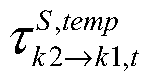


where,  represents transfer time periods of water from the node k2 to the node k1 in supply pipelines of the CHS,
  represents transfer time periods of water from the node k2 to the node k1 in return pipelines of the CHS, and
 represents a rounding down operator.
(2) The CHPD model established in (1) is transformed into a model in a matrix form.
In detail, the CHPD model is summarized as a following quadratic programming (QP) problem in the matrix form by a formula of:

where, xE represents variables of the EPS, and the variables of the EPS comprises
 and
and and xH represents variables of the CHS, and the variables of the CHS comprises
 and
and
CE represents the objective function of the EPS and CH represents the objective function of the CHS. CE refers to and CH refers to
AExE≤bE refers to the constraints of the EPS, which includes all constraints described in (1-2-1) . Each row in AE and bE has one-to-one correspondence with each constraint in the EPS. Each column in AE and bE has one-to-one correspondence with each variable in the EPS. Each element in AE is a coefficient of a variable corresponding to a column where the element is located in a constraint corresponding to a row where the element is located. Elements in each row in bE are inequality constant terms in the constraint corresponding to the elements.
AHxH≤bH refers to the constraints of the CHS except the constraints between the supply/return water temperature differences of the nodes and the heat outputs, which includes the constraints described in (1-2-2) except the constraints between the supply/return water temperature differences of the nodes and the heat outputs. Each row in AH and bH has one-to-one correspondence with each constraint in the CHS. Each column in AH and bH has one-to-one correspondence with each variable in the CHS. Each element in AH is a coefficient of a variable corresponding to a column where the element is located in a constraint corresponding to a row where the element is located. Elements in each row in bH are inequality constant terms in the constraint corresponding to the elements.
DxE+ExH≤f refers to the constraints between the supply/return water temperature differences of the nodes and the heat outputs described in (1-2-2) , i.e. coupling constraints on the EPS and the CHS. Each row in D, E and f has one-to-one correspondence with each constraint in the coupling constraints on the EPS and the CHS. Each row in D has one-to-one correspondence with each variable in the EPS. Each row in E has one-to-one correspondence with each variable in the CHS. Each element in D and E is a coefficient of a variable corresponding to a column where the element is located in a constraint corresponding to a row
where the element is located. Elements in each row in f are inequality constant terms in the constraint corresponding to the elements.
(3) The CHPD model in the matrix form described in (2) is solved by the Benders decomposition.
Fig. 3 is a flow chart of a method for solving a CHPD model according to another exemplary embodiment. As illustrated in Fig. 3, the method includes followings.
(3-1) Initializing: an iteration number m is initialized as 0, the number of optimal cuts p is initialized as 0 and the number of feasible cuts q is initialized as 0. Then an EPS problem is solved to obtain a solution as by a formula of

(3-2) A CHS problem is solved according to the solution by a formula of

(3-2-1) If the CHS problem in (3-2) is feasible, p is increased by 1 and an optimal cut is generated as follows,

where,  and λ represents a Lagrange multiplier of a constraint
 in (3-2) , and
 represents an objective value of the CHS problem in (3-2) .
(3-2-2) If the CHS problem in (3-2) is infeasible, q is increased by 1 and an feasible cut is generated as follows,


(3-2-2-1) denoting a feasibility problem of the CHS problem as a formula of:

(3-2-2-2) introducing a relaxation term ε to relax the feasibility problem of the CHS problem in (3-2-2-1) as a formula of:

(3-2-2-3) denoting a Lagrange multiplier of a constraint AHxH≤bH in the relaxed feasibility problem of the CHS problem (3-2-2-2) as and a Lagrange multiplier of a constraint
  in the relaxed feasibility problem (3-2-2-2) as
 and calculating
 and
and according to a formula of:

(3-3) The EPS problem is solved by a formula of

the iteration number m is increased by 1 and a solution is denoted as
(3-4) A convergence is checked.  the iteration is terminated to obtain the dispatch parameters for the EPS and the CHS according to the solution, in which Δ is a convergence threshold, for example, a value of Δ is 0.001, and then (3-5) is executed; and
  (3-2) is returned.
(3-5) The obtained solution is used as the dispatch parameters for the EPS and the CHS.
Embodiments of the present disclosure further provide a dispatch apparatus for controlling a CHP system. The device includes: a processor; and a memory for storing instructions executable by the processor. The processor is configured to perform the above method.
Embodiments of the present disclosure further provide a non-transitory computer readable storage medium. The non-transitory computer readable storage medium according to embodiments of the present disclosure may include instructions that, when executed by a processor of an apparatus, causes the apparatus to execute the above method.
The technical solutions provided by embodiments of the present disclosure have following advantageous effects.
In the technical solutions of the present disclosure, the CHPD model can be established by combining the dispatch model of the EPS and the dispatch model of the CHS. An algorithm for
solving the proposed CHPD model is provided based on Benders decomposition. In the provided algorithm for solving the proposed CHPD model, the operator of the EPS and the operator of the CHS can optimize corresponding internal systems independently, and the global optimal solution of the CHPD model can be obtained based on the interactive iteration between the boundary conditions of the EPS and CHS. The provided algorithm for solving the proposed CHPD model may have a good convergence rate and significantly improve an operation flexibility of the CHS.
Any process or method described in the flowing diagram or other means may be understood as a module, segment or portion including one or more executable instruction codes of the procedures configured to achieve a certain logic function or process, and the preferred embodiments of the present disclosure include other performances, in which the performance may be achieved in other orders instead of the order shown or discussed, such as in an almost simultaneous way or in an opposite order, which should be appreciated by those having ordinary skills in the art to which embodiments of the present disclosure belong.
The logic and/or procedures indicated in the flowing diagram or described in other means herein, such as a constant sequence table of the executable code for performing a logical function, may be implemented in any computer readable storage medium so as to be adopted by the code execution system, the device or the equipment (such a system based on the computer, a system including a processor or other systems fetching codes from the code execution system, the device and the equipment , and executing the codes) or to be combined with the code execution system, the device or the equipment to be used. With respect to the description of the present invention, “the computer readable storage medium” may include any device including, storing, communicating, propagating or transmitting program so as to be used by the code execution system, the device and the equipment or to be combined with the code execution system, the device or the equipment to be used. The computer readable medium includes specific examples (a non-exhaustive list) : the connecting portion (electronic device) having one or more arrangements of wire, the portable computer disc cartridge (a magnetic device) , the random access memory (RAM) , the read only memory (ROM) , the electrically programmable read only memory (EPROMM or the flash memory) , the optical fiber device and the compact disk read only memory (CDROM) . In addition, the computer readable storage medium even may be papers or other proper medium printed with program, as the papers or the proper medium may be optically scanned, then edited, interpreted or treated in other ways if necessary to obtain the program electronically which
may be stored in the computer memory.
It should be understood that, each part of the present disclosure may be implemented by the hardware, software, firmware or the combination thereof. In the above embodiments of the present invention, the plurality of procedures or methods may be implemented by the software or hardware stored in the computer memory and executed by the proper code execution system. For example, if the plurality of procedures or methods is to be implemented by the hardware, like in another embodiment of the present invention, any one of the following known technologies or the combination thereof may be used, such as discrete logic circuits having logic gates for implementing various logic functions upon an application of one or more data signals, application specific integrated circuits having appropriate logic gates, programmable gate arrays (PGA) , field programmable gate arrays (FPGA) .
It can be understood by those having the ordinary skills in the related art that all or part of the steps in the method of the above embodiments can be implemented by instructing related hardware via programs, the program may be stored in a computer readable storage medium, and the program includes one step or combinations of the steps of the method when the program is executed.
In addition, each functional unit in the present disclosure may be integrated in one progressing module, or each functional unit exists as an independent unit, or two or more functional units may be integrated in one module. The integrated module can be embodied in hardware, or software. If the integrated module is embodied in software and sold or used as an independent product, it can be stored in the computer readable storage medium.
The non-transitory computer-readable storage medium may be, but is not limited to, read-only memories, magnetic disks, or optical disks.
Reference throughout this specification to “an embodiment, ” “some embodiments, ” “one embodiment” , “another example, ” “an example, ” “a specific example, ” or “some examples, ” means that a particular feature, structure, material, or characteristic described in connection with the embodiment or example is included in at least one embodiment or example of the present disclosure. Thus, the appearances of the phrases such as “in some embodiments, ” “in one embodiment” , “in an embodiment” , “in another example, ” “in an example, ” “in a specific example, ” or “in some examples, ” in various places throughout this specification are not necessarily referring to the same embodiment or example of the present disclosure. Furthermore, the particular features, structures, materials, or characteristics may be combined in any suitable
manner in one or more embodiments or examples.
Although explanatory embodiments have been shown and described, it would be appreciated by those skilled in the art that the above embodiments cannot be construed to limit the present disclosure, and changes, alternatives, and modifications can be made in the embodiments without departing from spirit, principles and scope of the present disclosure.
Claims (19)
- A dispatch method for a combined heat and power CHP system, wherein, the CHP system comprises CHP units, non-CHP thermal units, wind farms and heating boilers; the CHP units, the non-CHP thermal units and the wind farms form an electric power system EPS of the CHP system; the CHP units and the heating boilers form a central heating system CHS of the CHP system; the EPS and the CHS are isolable; and the method comprises:establishing a combined heat and power dispatch CHPD model of the CHP system, wherein an objective function of the CHPD model is a minimizing function of a total generation cost of the CHP units, the non-CHP thermal units, the wind farms and the heating boilers and constraints of the CHPD model are established based on generation cost of the CHP units, the non-CHP thermal units, the wind farms and the heating boilers;solving the CHPD model based on Benders decomposition to obtain dispatch parameters for the EPS and the CHS; andcontrolling the EPS and the CHS according to the corresponding dispatch parameters respectively.
- The method according to claim 1, wherein the total generation cost is established by a formula of
 where, t represents a dispatch time period, T represents an index set of dispatch time periods, ICHP represents an index set of the CHP units, ITU represents an index set of the non-CHP thermal units, IWD represents an index set of the wind farms, IHB represents an index set of the heating boilers,represents a generation cost function of CHP unit i during period t,
 represents a generation cost function of non-CHP thermal unit i during the period t,
 represents a generation cost function of wind farm i during the period t, and
 represents a generation cost function of heating boiler i during the period t.
- The method according to claim 2, wherein the generation cost function of the CHP unit i during the period t is established by a formula of
 where,and
 represent generation cost coefficients of the CHP unit i,
 represents a power output of the CHP unit i during the period t, and
 represents a heat output of the CHP unit i during the period t.
- The method according to claim 2, wherein the generation cost function of the non-CHP thermal unit i during the period t is established by a formula of
 where,and
 represent generation cost coefficients of the non-CHP thermal unit i, and
 represents a power output of the non-CHP thermal unit i during the period t.
- The method according to claim 2, wherein the generation cost function of the wind farm i during the period t is established by a formula of
 where,represents a penalty coefficient,
 represents an available power output of the wind farm i during the period t and
 represents a power output of the wind farm i during the period t.
- The method according to claim 2, wherein the generation cost function of the heating boiler i during the period t is established by a formula of
 where,represents a generation cost coefficient of the heating boiler i, and
 represents a heat output of the wind farm i during the period t.
- The method according to claim 2, wherein, the constraints comprise constraints of the EPS and constraints of the CHS;the constraints of the EPS comprise: operation constraints of the CHP units, ramping up and down constraints of the CHP units, operation constraints of the non-CHP thermal units, ramping up and down constraints of the non-CHP thermal units, spinning reserve constraints of the non-CHP thermal units, operation constraints of the wind farms, a power balance constraint of the EPS, a line flow limit constraint of the EPS, and a spinning reserve constraint of the EPS; andthe constraints of the CHS comprise: constraints between supply/return water temperature differences of nodes and heat outputs, heat output constraints of the heating boilers, supply water temperature constraints at nodes with heat sources connected, constraints between supply/return water temperature differences of nodes and heat exchanges of heat exchange stations, return water temperature constraints of heat exchange stations, and operation constraints of heating networks of the CHS.
- The method according to claim 7, wherein the operation constraints of the CHP units are denoted by a formula of

 where,represents a power output of the CHP unit i during the period t,
 represents a heat output of the CHP unit i during the period t, NEi represents an index set of extreme points of the CHP unit i,
 represent respectively a power output at extreme point γ of the CHP unit i and a heat output at the extreme point γ of the CHP unit i, and
 represents a convex combination coefficient of the extreme point γ of the CHP unit i during the period t; and
 the ramping up and down constraints of the CHP units are denoted by a formula of
 where,represents an upward ramp rate of the CHP unit i,
 represents a downward ramp rate of the CHP unit i,
 represents a power output of the CHP unit i during period t+1, and ΔT represents a dispatch interval.
- The method according to claim 7, wherein the operation constraints of the non-CHP thermal units are denoted by a formula of
 where,represents an upper output bound of the non-CHP thermal unit i, Pi TU represents a lower output bound of the non-CHP thermal unit i and
 represents a power output of the non-CHP thermal unit i during the period t;
 the ramping up and down constraints of the non-CHP thermal units are denoted by a formula of
 where,represents an upward ramp rate of the non-CHP thermal unit i,
 represents a downward ramp rate of the non-CHP thermal unit,
 represents a power output of the non-CHP thermal unit i during period t+1, and ΔT represents a dispatch interval; and
 the spinning reserve constraints of the non-CHP thermal units are denoted by a formula of
 where,represents an upward spinning reserve contribution of the non-CHP thermal unit i during the period t, and
 represents a downward spinning reserve contribution of the non-CHP thermal unit i during the period t.
- The method according to claim 7, wherein the operation constraints of the wind farms are denoted by a formula of
 where,represents a power output of the wind farm i during the period t, and
 represents an available power output of the wind farm i during the period t.
- The method according to claim 7, wherein the power balance constraint of the EPS is denoted by a formula of
 where,represents a power output of the CHP unit i during the period t,
 represents a power output of the non-CHP thermal unit i during the period t,
 represents a power output of the wind farm i during the period t, ILD represents an index set of loads in the EPS and Dm, t represents a power demand of load m in the EPS during the period t;
 the line flow limit constraint of the EPS is denoted by a formula of
 where, IEPS represents an index set of buses in the EPS, SFj-l represents a shift factor for bus l on line j of the EPS,represents an index set of CHP units connected to the bus l of the EPS,
 represents an index set of non-CHP thermal units connected to the bus l of the EPS,
 represents an index set of wind farms connected to the bus l of the EPS,
 represents an index set of loads connected to the bus l of the EPS, Lj represents a flow limit of the line j of the EPS, and ILN represents an index set of lines in the EPS; and
 the spinning reserve constraint of the EPS is denoted by a formula of
 where,represents an upward spinning reserve contribution of the non-CHP thermal unit i during the period t,
 represents a downward spinning reserve contribution of the non-CHP thermal unit i during the period t, SRUt represents an upward spinning reserve demand of the EPS during the period t and SRDt represents a downward spinning reserve demand of the EPS during the period t.
- The method according to claim 7, wherein the constraints between the supply/return water temperature differences of the nodes and the heat outputs are denoted by a formula of
 where,represents an index set of CHP units connected to node k of the CHS,
 represents an index set of heating boilers connected to the node k of the CHS,
 represents a heat output of the CHP unit i during the period t,
 represents a heat output of the heating boiler i during the period t, C represents a specific heat capacity of water,
 represents a total mass flow rate of water at the node k of the CHS,
 represents a water temperature of the node k in supply pipelines of the CHS during the period t,
 represents a water temperature of the node k in return pipelines of the CHS during the period t, and
 represents an index set of nodes with heat sources connected in the CHS;
 the heat output constraints of the heating boilers are denoted by a formula of
 where,represents an upper heat output bound of the heating boiler i; and
 the supply water temperature constraints at the nodes with heat sources connected are denoted by a formula of
 where,represents an upper bound of the water temperature at the node k in the supply pipelines of the CHS and
 represents a lower bound of the water temperature at the node k in the supply pipelines of the CHS.
- The method according to claim 7, wherein the constraints between the supply/return water temperature differences of the nodes and the heat exchanges of the heat exchange stations in the CHS are denoted by a formula of
 where,represents an index set of heat exchange stations connected to node k of the CHS,
 represents a heat exchange of heat exchange station n during the period t, C represents a specific heat capacity of water,
 represents a total mass flow rate of water at the node k of the CHS,
 represents a water temperature of the node k in supply pipelines of the CHS during the period t,
 represents a water temperature of the node k in return pipelines of the CHS during the period t, and
 represents an index set of nodes with heat exchange stations connected in the CHS; and
 the return water temperature constraints of the heat exchange stations are denoted by a formula of
 where,represents an upper bound of the water temperature at the node k in the return pipelines of the CHS and
 represents a lower bound of the water temperature at the node k in the return pipelines of the CHS.
- The method according to claim 7, wherein the operation constraints of the heating networks of the CHS are denoted by a formula of

 where,represents a mass flow rate of water transferred from node k2 to node k1 in supply pipelines of the CHS,
 represents a mass flow rate of return water transferred from the node k2 to the node k1 in return pipelines of the CHS,
 represents an index set of child nodes of the node k1 in supply pipelines of the CHS,
 represents an index set of child nodes of the node k1 in return pipelines of the CHS,
 represents an ambient temperature during the period t,
 represents a heat transfer factor of water transferred from the node k2 to the node k1 in supply pipelines of the CHS,
 represents a heat transfer factor of water transferred from the node k2 to the node k1 in return pipelines of the CHS, wherein
 and
and are calculated by a formula of
 where,represents a heat transfer coefficient per unit length of pipeline from the node k2 to the node k1 in the supply pipelines of the CHS,
 represents a heat transfer coefficient per unit length of pipeline from the node k2 to the node k1 in the return pipelines of the CHS,
 represents a length of the supply pipeline from the node k2 to the node k1,
 represents a length of the return pipeline from the node k2 to the node k1;
 and
and are intermediate variables representing temperature of the node k1 and only considering a transfer delay of water from its child node k2, wherein
 and
and are denoted by a formula of
 where,represents transfer time periods of water from the node k2 to the node k1 in supply pipelines of the CHS,
 represents transfer time periods of water from the node k2 to the node k1 in return pipelines of the CHS, and
 represents a rounding down operator.
- The method according to claim 7, wherein the CHPD model is summarized as a following quadratic programming QP problem by a formula of:
 where, xE represents variables of the EPS, and the variables of the EPS comprises
 and
and in which
 represents a power output of the non-CHP thermal unit i during the period t,
 represents an upward spinning reserve contribution of the non-CHP thermal unit i during the period t,
 represents a downward spinning reserve contribution of the non-CHP thermal unit i during the period t,
 represents a power output of the wind farm i during the period t,
 represents a power output of the CHP unit i during the period t,
 represents a heat output of the CHP unit i during the period t and
 represents a coefficient of extreme point γ of the CHP unit i during the period t; xH represents variables of the CHS, and the variables of the CHS comprises
 and
and in which
 represents a heat output of the heating boiler i during the period t,
 represents a water temperature of the node k in supply pipelines of the CHS during the period t, and
 represents a water temperature of the node k in return pipelines of the CHS during the period t; AExE≤bE refers to the constraints of the EPS; AHxH≤bH refers to the constraints of the CHS except the constraints between the supply/return water temperature differences of the nodes and the heat outputs; and DxE+ExH≤f refers to the constraints between the supply/return water temperature differences of the nodes and the heat outputs.
- The method according to claim 15, wherein solving the CHPD model based on Benders decomposition to obtain dispatch parameters for the EPS and the CHS comprises:splitting the QP problem into an EPS problem and a CHS problem;initializing an iteration number m as 0, the number of optimal cuts p as 0, and the number of feasible cuts q as 0;solving the EPS problem to obtain a solution asby a formula of

 solving the CHS problem according to the solutionby a formula of
 if the CHS problem is feasible, increasing p by 1 and generating an optimal cut of
 if the CHS problem is infeasible, increasing q by 1 and generating an feasible cut of
 solving the EPS problem by a formula of
 increasing the iteration number m by 1 and denoting a solution as
 ifterminating the iteration to obtain the dispatch parameters for the EPS and the CHS according to the solution; and
 ifreturning to act of solving the CHS problem according to the solution

- The method according to claim 16, whereinand λ represents a Lagrange multiplier of a constraint
 and
and represents an objective value of the CHS problem;
 and
and are calculated according to following acts:
 denoting a feasibility problem of the CHS problem as a formula of:
 introducing a relaxation term ε to relax the feasibility problem of the CHS problem as a formula of:
 denoting a Lagrange multiplier of a constraint AHxH≤bH in the relaxed feasibility problem of the CHS problem asand a Lagrange multiplier of a constraint
 in the relaxed feasibility problem of the CHS problem as
 and calculating
 and
and according to a formula of:

- A dispatch apparatus for controlling a combined heat and power CHP system, wherein, the CHP system comprises CHP units, non-CHP thermal units, wind farms and heating boilers; the CHP units, the non-CHP thermal units and the wind farms form an electric power system EPS of the CHP system; the CHP units and the heating boilers form a central heating system CHS of the CHP system; the EPS and the CHS are isolable; and the device comprises:a processor; anda memory for storing instructions executable by the processor,wherein the processor is configured to:establish a combined heat and power dispatch CHPD model of the CHP system, wherein an objective function of the CHPD model is a minimizing function of a total generation cost of the CHP units, the non-CHP thermal units, the wind farms and the heating boilers and constraints of the CHPD model are established based on generation cost of the CHP units, the non-CHP thermal units, the wind farms and the heating boilers;solve the CHPD model based on Benders decomposition to obtain dispatch parameters for the EPS and the CHS; andcontrol the EPS and the CHS according to the corresponding dispatch parameters respectively.
- A non-transitory computer-readable storage medium having stored therein instructions that, when executed by a processor of a computer, causes the computer to perform a dispatch method for a combined heat and power CHP system, wherein the CHP system comprises CHP units, non-CHP thermal units, wind farms and heating boilers; the CHP units, the non-CHP thermal units and the wind farms form an electric power system EPS of the CHP system; the CHP units and the heating boilers form a central heating system CHS of the CHP system; the EPS and the CHS are isolable; and the method comprises:establishing a combined heat and power dispatch CHPD model of the CHP system, wherein an objective function of the CHPD model is a minimizing function of a total generation cost of the CHP units, the non-CHP thermal units, the wind farms and the heating boilers and constraints of the CHPD model are established based on generation cost of the CHP units, the non-CHP thermal units, the wind farms and the heating boilers;solving the CHPD model based on Benders decomposition to obtain dispatch parameters for the EPS and the CHS; andcontrolling the EPS and the CHS according to the corresponding dispatch parameters respectively.
Priority Applications (1)
| Application Number | Priority Date | Filing Date | Title |
|---|---|---|---|
| US15/736,576 US10620594B2 (en) | 2017-02-22 | 2017-12-01 | Dispatch method and apparatus for combined heat and power system |
Applications Claiming Priority (2)
| Application Number | Priority Date | Filing Date | Title |
|---|---|---|---|
| CN201710097510.9A CN106815661B (en) | 2017-02-22 | 2017-02-22 | A Decomposition Coordination Scheduling Method for Combined Heat and Power System |
| CN201710097510.9 | 2017-02-22 |
Publications (1)
| Publication Number | Publication Date |
|---|---|
| WO2018153138A1 true WO2018153138A1 (en) | 2018-08-30 |
Family
ID=59111684
Family Applications (1)
| Application Number | Title | Priority Date | Filing Date |
|---|---|---|---|
| PCT/CN2017/114317 Ceased WO2018153138A1 (en) | 2017-02-22 | 2017-12-01 | Dispatch method and apparatus for combined heat and power system |
Country Status (3)
| Country | Link |
|---|---|
| US (1) | US10620594B2 (en) |
| CN (1) | CN106815661B (en) |
| WO (1) | WO2018153138A1 (en) |
Cited By (5)
| Publication number | Priority date | Publication date | Assignee | Title |
|---|---|---|---|---|
| CN109783986A (en) * | 2019-02-26 | 2019-05-21 | 上海交通大学 | Isolated island pattern synthesis energy resource system based on power conservation combines trend acquisition methods |
| CN109978233A (en) * | 2019-02-20 | 2019-07-05 | 中国电力科学研究院有限公司 | The Optimization Scheduling a few days ago and system of long-term electricity trade contract in a kind of consideration |
| CN112308433A (en) * | 2020-11-03 | 2021-02-02 | 东北电力大学 | Wind power dispatching method and system |
| CN115496378A (en) * | 2022-09-27 | 2022-12-20 | 四川省电力行业协会 | An economical dispatching method of power system considering the benefits of wind energy emission reduction |
| CN116624915A (en) * | 2021-08-25 | 2023-08-22 | 陕西启迪瑞行清洁能源研究院有限公司 | A Method for Determining Hydraulic Disorder of Pipe Network Based on Temperature Difference Between Supply and Return Water |
Families Citing this family (38)
| Publication number | Priority date | Publication date | Assignee | Title |
|---|---|---|---|---|
| CN106815661B (en) | 2017-02-22 | 2020-10-20 | 清华大学 | A Decomposition Coordination Scheduling Method for Combined Heat and Power System |
| CN106998079B (en) * | 2017-04-28 | 2020-05-05 | 东南大学 | A Modeling Method for Combined Heat and Power Optimal Scheduling Model |
| CN107887903B (en) * | 2017-10-31 | 2020-12-04 | 深圳供电局有限公司 | Robust optimal scheduling method for microgrid considering frequency characteristics of components |
| CN107977744B (en) * | 2017-11-30 | 2021-07-13 | 三峡大学 | A Day-ahead Robust Scheduling Method for Power System Based on Traditional Benders Decomposition Method |
| CN107862419A (en) * | 2017-12-08 | 2018-03-30 | 清华大学 | The low-carbon Optimization Scheduling and system of a kind of multipotency source network |
| CN108155644B (en) * | 2017-12-26 | 2020-04-24 | 清华大学 | Dynamic heat supply system and power system coupling scheduling method considering auxiliary service |
| CN108599266B (en) * | 2018-03-21 | 2020-05-08 | 浙江大学 | Demand side response scheduling method under electricity-gas-heat multi-energy flow coupling |
| CN108876196B (en) * | 2018-07-18 | 2021-10-19 | 国网冀北电力有限公司 | Alternate Iterative Optimal Scheduling Method Based on Non-salient Force Characteristics of Cogeneration Units |
| CN109634113A (en) * | 2018-10-18 | 2019-04-16 | 国网安徽省电力有限公司 | The control method and device of compressed-air energy-storage system in coupled thermomechanics market |
| CN109657984A (en) * | 2018-12-20 | 2019-04-19 | 清华-伯克利深圳学院筹备办公室 | Optimization Scheduling, device, electronic equipment and the storage medium of energy resource system |
| CN109657885A (en) * | 2019-02-25 | 2019-04-19 | 华南理工大学 | A kind of electric-thermal net coordinated operation optimization method based on more searcher algorithms |
| CN111697615A (en) * | 2019-03-15 | 2020-09-22 | 新奥数能科技有限公司 | Method and device for determining abandoned wind absorption and gear adjustment times |
| CN110230842A (en) * | 2019-03-25 | 2019-09-13 | 国网辽宁省电力有限公司 | A kind of heat storage electric boiler " peak load shifting " control method based on multiple agent |
| CN112016726B (en) * | 2019-05-28 | 2025-07-15 | 中国电力科学研究院有限公司 | A coordination optimization method and system for inter-regional contact lines |
| CN112288120A (en) * | 2019-07-26 | 2021-01-29 | 上海漕泾热电有限责任公司 | Production scheduling real-time optimization system and method for cogeneration unit |
| CN110535120A (en) * | 2019-08-16 | 2019-12-03 | 华南理工大学 | Distributed Optimal Scheduling Method of Electric-Gas Interconnected System Considering Air Pollution Diffusion |
| CN110826228B (en) * | 2019-11-07 | 2022-07-01 | 国网四川省电力公司电力科学研究院 | Regional power grid operation quality limit evaluation method |
| CN110991845B (en) * | 2019-11-25 | 2023-06-23 | 国网节能服务有限公司 | Distributed cooperative scheduling method for electric-thermal coupling system |
| CN111415045B (en) * | 2020-03-24 | 2022-10-11 | 华北电力大学 | Two-stage operation optimization method for rural biomass comprehensive energy system |
| CN111952956B (en) * | 2020-07-02 | 2024-07-09 | 清华大学 | A power system dispatching method considering voltage sensitive load reserve |
| CN114069603A (en) * | 2020-08-06 | 2022-02-18 | 中国电力科学研究院有限公司 | New energy consumption method and system considering electric heating boiler |
| CN112070358A (en) * | 2020-08-11 | 2020-12-11 | 山东电力研究院 | Method and system for determining electric load adjustment interval of low-vacuum heat supply unit |
| CN112013446B (en) * | 2020-08-27 | 2021-09-14 | 常州英集动力科技有限公司 | Heat supply network balanced heating and cooling method and system for solving temperature transmission delay |
| CN112734591A (en) * | 2020-11-26 | 2021-04-30 | 清华大学 | Electric heating comprehensive coordination scheduling method and device, equipment and medium |
| CN112636330B (en) * | 2020-12-02 | 2023-01-10 | 上海交通大学 | Comprehensive energy system peak regulation method based on user contribution behaviors |
| CN113177185B (en) * | 2021-04-25 | 2023-05-23 | 国网吉林省电力有限公司 | Comprehensive thermoelectric system scheduling method based on tightening McCormick method |
| CN113191638B (en) * | 2021-04-30 | 2024-10-29 | 清华大学 | Electricity and heat coordinated scheduling method and device taking into account dynamic characteristics of heat transfer in heating network |
| CN115579889A (en) * | 2021-06-21 | 2023-01-06 | 青岛海尔智能技术研发有限公司 | Combined heat and power system and its island operation control method and device |
| CN113762781B (en) * | 2021-09-10 | 2022-07-12 | 国网江苏省电力有限公司常州供电分公司 | Optimized scheduling method and device for electricity-gas integrated energy system considering electricity to gas |
| CN114021911A (en) * | 2021-10-21 | 2022-02-08 | 国网山西省电力公司电力科学研究院 | Low-carbon optimization scheduling method for comprehensive energy system of carbon-containing capture device |
| CN114861404B (en) * | 2022-04-12 | 2025-01-14 | 华南理工大学 | A real-time dispatching method for electric-thermal integrated energy system with guaranteed feasibility |
| CN115660304A (en) * | 2022-07-20 | 2023-01-31 | 国网山东省电力公司 | A planning method for rural comprehensive energy system based on multi-industry collaboration |
| CN115342421B (en) * | 2022-08-15 | 2025-07-08 | 华能国际电力股份有限公司 | Control method, device and equipment for load of heat supply unit and storage medium |
| CN116341814A (en) * | 2022-12-23 | 2023-06-27 | 清华大学 | Electrothermal coupling system optimization scheduling method, device, electronic equipment and storage medium |
| US20250226653A1 (en) * | 2023-04-13 | 2025-07-10 | Dalian University Of Technology | A coordination method of electricity supply and recipient market day-ahead spot clearing considering hydropower absorption |
| CN117151426B (en) * | 2023-10-25 | 2024-02-09 | 广东电网有限责任公司中山供电局 | Electrothermal energy system scheduling method and related device based on asymmetry of electrothermal information |
| CN117826907B (en) * | 2024-03-01 | 2024-06-11 | 中集安瑞科能源系统(上海)有限公司 | Control method of cascade cogeneration device |
| CN120975405B (en) * | 2025-10-17 | 2026-02-10 | 东南大学 | CHP Low-Carbon Dispatch Method and System Considering Carbon Emission-Fuel-Power Coupling |
Citations (7)
| Publication number | Priority date | Publication date | Assignee | Title |
|---|---|---|---|---|
| CN102410594A (en) * | 2011-10-23 | 2012-04-11 | 重庆市电力公司 | Wind power output dispatching system and method based on joint control of combined heat and power generation and cooling load |
| CN102510099A (en) * | 2011-10-23 | 2012-06-20 | 西安交通大学 | Heat and electricity joint scheduling system with gas combined cycle unit and scheduling method thereof |
| EP2779040A1 (en) * | 2013-03-15 | 2014-09-17 | Honeywell International Inc. | Modeling energy conversion in systems |
| CN106294961A (en) * | 2016-08-03 | 2017-01-04 | 清华大学 | A kind of meter and the central heating system modeling method of pipe network heat accumulation benefit |
| CN106339772A (en) * | 2016-08-11 | 2017-01-18 | 清华大学 | Heat supply pipe network thermal storage efficiency-based thermal-electric joint optimal dispatching method |
| CN106815661A (en) * | 2017-02-22 | 2017-06-09 | 清华大学 | A kind of composition decomposition dispatching method of CHP system |
| CN106992555A (en) * | 2017-04-25 | 2017-07-28 | 国网吉林省电力有限公司 | A Distributed Scheduling Method for Combined Heat and Power System in Auxiliary Service Market Environment |
Family Cites Families (8)
| Publication number | Priority date | Publication date | Assignee | Title |
|---|---|---|---|---|
| US7991512B2 (en) * | 2007-08-28 | 2011-08-02 | General Electric Company | Hybrid robust predictive optimization method of power system dispatch |
| US20150318699A2 (en) * | 2011-09-29 | 2015-11-05 | James Frederick Wolter | Power generation system with integrated renewable energy generation, energy storage, and power control |
| CN102506519B (en) * | 2011-10-23 | 2013-12-11 | 重庆市电力公司电力科学研究院 | Heat and power cogenerator unit and wind power generator unit combined heat supply system and scheduling method thereof |
| CN103728653A (en) | 2013-07-02 | 2014-04-16 | 中国工程物理研究院核物理与化学研究所 | Sample preparation system of carbon-14 in solid sample |
| US10290064B2 (en) * | 2014-10-21 | 2019-05-14 | Accenture Global Services Limited | System, method and apparatus for capacity determination for micro grid and tangible computer readable medium |
| US10211637B2 (en) * | 2014-11-13 | 2019-02-19 | The University Of Hong Kong | Fast generation adjustment algorithm for energy management system |
| CN106253350B (en) * | 2016-08-11 | 2019-03-05 | 清华大学 | Combination method of combined heat-electricity unit based on heat storage benefit of heating pipe network |
| CN106208075B (en) * | 2016-08-29 | 2019-03-05 | 清华大学 | Multi-region decomposition coordination dynamic economic dispatch method based on modified generalized Benders decomposition |
-
2017
- 2017-02-22 CN CN201710097510.9A patent/CN106815661B/en active Active
- 2017-12-01 US US15/736,576 patent/US10620594B2/en active Active
- 2017-12-01 WO PCT/CN2017/114317 patent/WO2018153138A1/en not_active Ceased
Patent Citations (7)
| Publication number | Priority date | Publication date | Assignee | Title |
|---|---|---|---|---|
| CN102410594A (en) * | 2011-10-23 | 2012-04-11 | 重庆市电力公司 | Wind power output dispatching system and method based on joint control of combined heat and power generation and cooling load |
| CN102510099A (en) * | 2011-10-23 | 2012-06-20 | 西安交通大学 | Heat and electricity joint scheduling system with gas combined cycle unit and scheduling method thereof |
| EP2779040A1 (en) * | 2013-03-15 | 2014-09-17 | Honeywell International Inc. | Modeling energy conversion in systems |
| CN106294961A (en) * | 2016-08-03 | 2017-01-04 | 清华大学 | A kind of meter and the central heating system modeling method of pipe network heat accumulation benefit |
| CN106339772A (en) * | 2016-08-11 | 2017-01-18 | 清华大学 | Heat supply pipe network thermal storage efficiency-based thermal-electric joint optimal dispatching method |
| CN106815661A (en) * | 2017-02-22 | 2017-06-09 | 清华大学 | A kind of composition decomposition dispatching method of CHP system |
| CN106992555A (en) * | 2017-04-25 | 2017-07-28 | 国网吉林省电力有限公司 | A Distributed Scheduling Method for Combined Heat and Power System in Auxiliary Service Market Environment |
Cited By (7)
| Publication number | Priority date | Publication date | Assignee | Title |
|---|---|---|---|---|
| CN109978233A (en) * | 2019-02-20 | 2019-07-05 | 中国电力科学研究院有限公司 | The Optimization Scheduling a few days ago and system of long-term electricity trade contract in a kind of consideration |
| CN109783986A (en) * | 2019-02-26 | 2019-05-21 | 上海交通大学 | Isolated island pattern synthesis energy resource system based on power conservation combines trend acquisition methods |
| CN112308433A (en) * | 2020-11-03 | 2021-02-02 | 东北电力大学 | Wind power dispatching method and system |
| CN112308433B (en) * | 2020-11-03 | 2023-11-24 | 东北电力大学 | A wind power power dispatching method and system |
| CN116624915A (en) * | 2021-08-25 | 2023-08-22 | 陕西启迪瑞行清洁能源研究院有限公司 | A Method for Determining Hydraulic Disorder of Pipe Network Based on Temperature Difference Between Supply and Return Water |
| CN115496378A (en) * | 2022-09-27 | 2022-12-20 | 四川省电力行业协会 | An economical dispatching method of power system considering the benefits of wind energy emission reduction |
| CN115496378B (en) * | 2022-09-27 | 2023-12-01 | 四川省电力行业协会 | Economic dispatching method for electric power system with wind energy emission reduction benefit |
Also Published As
| Publication number | Publication date |
|---|---|
| CN106815661A (en) | 2017-06-09 |
| US10620594B2 (en) | 2020-04-14 |
| CN106815661B (en) | 2020-10-20 |
| US20180356774A1 (en) | 2018-12-13 |
Similar Documents
| Publication | Publication Date | Title |
|---|---|---|
| US10620594B2 (en) | Dispatch method and apparatus for combined heat and power system | |
| US10361561B2 (en) | Dispatching method and device for integrated transmission and distribution network | |
| Liang et al. | A zoom feature for a dynamic programming solution to economic dispatch including transmission losses | |
| US11923685B2 (en) | Reactive power and voltage control method | |
| US10673237B2 (en) | Reactive power optimization method | |
| US9721313B2 (en) | Method and device for identifying feasibility of transmission interface constraint in online rolling dispatching | |
| US11239658B2 (en) | Dispatching method and device for integrated transmission and distribution network | |
| CN109546646A (en) | A kind of decentralized clearing method, device, equipment and medium for regional electricity spot market | |
| CN113270895B (en) | A Day-ahead Robust Joint Optimization Method and System for Electric Energy and Ancillary Services Markets | |
| CN116345564B (en) | Multi-time-scale distributed collaborative optimization scheduling method and system for comprehensive energy system | |
| CN113360289B (en) | Distributed collaborative optimization method of multi-region integrated energy system based on edge computing | |
| Mishra et al. | Enabling cyber‐physical demand response in smart grids via conjoint communication and controller design | |
| US11411406B2 (en) | Method, apparatus, and storage medium for controlling combined heat and power system | |
| CN112653122A (en) | Storage-transmission joint planning method for coping with peak shaving deficiency and transmission blockage | |
| CN111930681B (en) | Computing device and related product | |
| CN115659098A (en) | Distributed new energy consumption capacity calculation method, device, equipment and medium | |
| CN112256427B (en) | Large-scale resource rapid allocation device based on improved branch limit method | |
| US11947325B2 (en) | Controller for microgrid powered interconnected greenhouses | |
| CN113469328B (en) | Devices, boards, methods and readable storage media for performing revolution pass-through | |
| CN112699922A (en) | Self-adaptive clustering method and system based on intra-region distance | |
| CN115000957B (en) | Resource scheduling optimization method and system considering uncertainty of net load among moments | |
| CN113469326B (en) | Integrated circuit device and board for executing pruning optimization in neural network model | |
| JP6670403B2 (en) | Power system evaluation method and evaluation device | |
| CN117039851A (en) | Power grid dispatching methods, devices, equipment and storage media | |
| CN114418232A (en) | Energy storage system operation optimization method and system, server and storage medium |
Legal Events
| Date | Code | Title | Description |
|---|---|---|---|
| 121 | Ep: the epo has been informed by wipo that ep was designated in this application |
Ref document number: 17898015 Country of ref document: EP Kind code of ref document: A1 |
|
| NENP | Non-entry into the national phase |
Ref country code: DE |
|
| 122 | Ep: pct application non-entry in european phase |
Ref document number: 17898015 Country of ref document: EP Kind code of ref document: A1 |