WO2018150699A1 - Optical fiber sensor - Google Patents
Optical fiber sensor Download PDFInfo
- Publication number
- WO2018150699A1 WO2018150699A1 PCT/JP2017/044173 JP2017044173W WO2018150699A1 WO 2018150699 A1 WO2018150699 A1 WO 2018150699A1 JP 2017044173 W JP2017044173 W JP 2017044173W WO 2018150699 A1 WO2018150699 A1 WO 2018150699A1
- Authority
- WO
- WIPO (PCT)
- Prior art keywords
- core
- optical fiber
- central core
- fiber sensor
- refractive index
- Prior art date
Links
- 239000013307 optical fiber Substances 0.000 title claims abstract description 104
- 230000002093 peripheral effect Effects 0.000 claims abstract description 61
- 230000003287 optical effect Effects 0.000 claims abstract description 42
- 229910052732 germanium Inorganic materials 0.000 claims description 19
- GNPVGFCGXDBREM-UHFFFAOYSA-N germanium atom Chemical compound [Ge] GNPVGFCGXDBREM-UHFFFAOYSA-N 0.000 claims description 19
- 239000000654 additive Substances 0.000 claims description 16
- 230000000996 additive effect Effects 0.000 claims description 14
- 239000000835 fiber Substances 0.000 claims description 13
- 239000011162 core material Substances 0.000 description 284
- 239000000463 material Substances 0.000 description 11
- 238000005259 measurement Methods 0.000 description 8
- 238000009987 spinning Methods 0.000 description 6
- 239000011248 coating agent Substances 0.000 description 5
- 238000000576 coating method Methods 0.000 description 5
- 238000004519 manufacturing process Methods 0.000 description 5
- 238000000034 method Methods 0.000 description 5
- 238000002168 optical frequency-domain reflectometry Methods 0.000 description 5
- VYPSYNLAJGMNEJ-UHFFFAOYSA-N Silicium dioxide Chemical compound O=[Si]=O VYPSYNLAJGMNEJ-UHFFFAOYSA-N 0.000 description 3
- 238000010586 diagram Methods 0.000 description 3
- 230000000694 effects Effects 0.000 description 3
- 238000009826 distribution Methods 0.000 description 2
- ZOXJGFHDIHLPTG-UHFFFAOYSA-N Boron Chemical compound [B] ZOXJGFHDIHLPTG-UHFFFAOYSA-N 0.000 description 1
- PXGOKWXKJXAPGV-UHFFFAOYSA-N Fluorine Chemical compound FF PXGOKWXKJXAPGV-UHFFFAOYSA-N 0.000 description 1
- 238000003491 array Methods 0.000 description 1
- 229910052796 boron Inorganic materials 0.000 description 1
- 238000005253 cladding Methods 0.000 description 1
- 229910052731 fluorine Inorganic materials 0.000 description 1
- 239000011737 fluorine Substances 0.000 description 1
- 239000011521 glass Substances 0.000 description 1
- 230000001678 irradiating effect Effects 0.000 description 1
- 238000002844 melting Methods 0.000 description 1
- 230000008018 melting Effects 0.000 description 1
- 230000000737 periodic effect Effects 0.000 description 1
- 238000004804 winding Methods 0.000 description 1
Images


Classifications
-
- G—PHYSICS
- G01—MEASURING; TESTING
- G01D—MEASURING NOT SPECIALLY ADAPTED FOR A SPECIFIC VARIABLE; ARRANGEMENTS FOR MEASURING TWO OR MORE VARIABLES NOT COVERED IN A SINGLE OTHER SUBCLASS; TARIFF METERING APPARATUS; MEASURING OR TESTING NOT OTHERWISE PROVIDED FOR
- G01D5/00—Mechanical means for transferring the output of a sensing member; Means for converting the output of a sensing member to another variable where the form or nature of the sensing member does not constrain the means for converting; Transducers not specially adapted for a specific variable
- G01D5/26—Mechanical means for transferring the output of a sensing member; Means for converting the output of a sensing member to another variable where the form or nature of the sensing member does not constrain the means for converting; Transducers not specially adapted for a specific variable characterised by optical transfer means, i.e. using infrared, visible, or ultraviolet light
- G01D5/32—Mechanical means for transferring the output of a sensing member; Means for converting the output of a sensing member to another variable where the form or nature of the sensing member does not constrain the means for converting; Transducers not specially adapted for a specific variable characterised by optical transfer means, i.e. using infrared, visible, or ultraviolet light with attenuation or whole or partial obturation of beams of light
- G01D5/34—Mechanical means for transferring the output of a sensing member; Means for converting the output of a sensing member to another variable where the form or nature of the sensing member does not constrain the means for converting; Transducers not specially adapted for a specific variable characterised by optical transfer means, i.e. using infrared, visible, or ultraviolet light with attenuation or whole or partial obturation of beams of light the beams of light being detected by photocells
- G01D5/353—Mechanical means for transferring the output of a sensing member; Means for converting the output of a sensing member to another variable where the form or nature of the sensing member does not constrain the means for converting; Transducers not specially adapted for a specific variable characterised by optical transfer means, i.e. using infrared, visible, or ultraviolet light with attenuation or whole or partial obturation of beams of light the beams of light being detected by photocells influencing the transmission properties of an optical fibre
- G01D5/3537—Optical fibre sensor using a particular arrangement of the optical fibre itself
- G01D5/3538—Optical fibre sensor using a particular arrangement of the optical fibre itself using a particular type of fiber, e.g. fibre with several cores, PANDA fiber, fiber with an elliptic core or the like
-
- G—PHYSICS
- G01—MEASURING; TESTING
- G01D—MEASURING NOT SPECIALLY ADAPTED FOR A SPECIFIC VARIABLE; ARRANGEMENTS FOR MEASURING TWO OR MORE VARIABLES NOT COVERED IN A SINGLE OTHER SUBCLASS; TARIFF METERING APPARATUS; MEASURING OR TESTING NOT OTHERWISE PROVIDED FOR
- G01D5/00—Mechanical means for transferring the output of a sensing member; Means for converting the output of a sensing member to another variable where the form or nature of the sensing member does not constrain the means for converting; Transducers not specially adapted for a specific variable
- G01D5/26—Mechanical means for transferring the output of a sensing member; Means for converting the output of a sensing member to another variable where the form or nature of the sensing member does not constrain the means for converting; Transducers not specially adapted for a specific variable characterised by optical transfer means, i.e. using infrared, visible, or ultraviolet light
- G01D5/32—Mechanical means for transferring the output of a sensing member; Means for converting the output of a sensing member to another variable where the form or nature of the sensing member does not constrain the means for converting; Transducers not specially adapted for a specific variable characterised by optical transfer means, i.e. using infrared, visible, or ultraviolet light with attenuation or whole or partial obturation of beams of light
- G01D5/34—Mechanical means for transferring the output of a sensing member; Means for converting the output of a sensing member to another variable where the form or nature of the sensing member does not constrain the means for converting; Transducers not specially adapted for a specific variable characterised by optical transfer means, i.e. using infrared, visible, or ultraviolet light with attenuation or whole or partial obturation of beams of light the beams of light being detected by photocells
- G01D5/353—Mechanical means for transferring the output of a sensing member; Means for converting the output of a sensing member to another variable where the form or nature of the sensing member does not constrain the means for converting; Transducers not specially adapted for a specific variable characterised by optical transfer means, i.e. using infrared, visible, or ultraviolet light with attenuation or whole or partial obturation of beams of light the beams of light being detected by photocells influencing the transmission properties of an optical fibre
-
- G—PHYSICS
- G01—MEASURING; TESTING
- G01B—MEASURING LENGTH, THICKNESS OR SIMILAR LINEAR DIMENSIONS; MEASURING ANGLES; MEASURING AREAS; MEASURING IRREGULARITIES OF SURFACES OR CONTOURS
- G01B11/00—Measuring arrangements characterised by the use of optical techniques
- G01B11/16—Measuring arrangements characterised by the use of optical techniques for measuring the deformation in a solid, e.g. optical strain gauge
- G01B11/161—Measuring arrangements characterised by the use of optical techniques for measuring the deformation in a solid, e.g. optical strain gauge by interferometric means
-
- G—PHYSICS
- G02—OPTICS
- G02B—OPTICAL ELEMENTS, SYSTEMS OR APPARATUS
- G02B6/00—Light guides; Structural details of arrangements comprising light guides and other optical elements, e.g. couplings
- G02B6/02—Optical fibres with cladding with or without a coating
- G02B6/02004—Optical fibres with cladding with or without a coating characterised by the core effective area or mode field radius
- G02B6/02028—Small effective area or mode field radius, e.g. for allowing nonlinear effects
-
- G—PHYSICS
- G02—OPTICS
- G02B—OPTICAL ELEMENTS, SYSTEMS OR APPARATUS
- G02B6/00—Light guides; Structural details of arrangements comprising light guides and other optical elements, e.g. couplings
- G02B6/02—Optical fibres with cladding with or without a coating
- G02B6/02042—Multicore optical fibres
-
- G—PHYSICS
- G02—OPTICS
- G02B—OPTICAL ELEMENTS, SYSTEMS OR APPARATUS
- G02B6/00—Light guides; Structural details of arrangements comprising light guides and other optical elements, e.g. couplings
- G02B6/02—Optical fibres with cladding with or without a coating
- G02B6/02057—Optical fibres with cladding with or without a coating comprising gratings
- G02B6/02076—Refractive index modulation gratings, e.g. Bragg gratings
-
- G—PHYSICS
- G01—MEASURING; TESTING
- G01D—MEASURING NOT SPECIALLY ADAPTED FOR A SPECIFIC VARIABLE; ARRANGEMENTS FOR MEASURING TWO OR MORE VARIABLES NOT COVERED IN A SINGLE OTHER SUBCLASS; TARIFF METERING APPARATUS; MEASURING OR TESTING NOT OTHERWISE PROVIDED FOR
- G01D5/00—Mechanical means for transferring the output of a sensing member; Means for converting the output of a sensing member to another variable where the form or nature of the sensing member does not constrain the means for converting; Transducers not specially adapted for a specific variable
- G01D5/26—Mechanical means for transferring the output of a sensing member; Means for converting the output of a sensing member to another variable where the form or nature of the sensing member does not constrain the means for converting; Transducers not specially adapted for a specific variable characterised by optical transfer means, i.e. using infrared, visible, or ultraviolet light
- G01D5/32—Mechanical means for transferring the output of a sensing member; Means for converting the output of a sensing member to another variable where the form or nature of the sensing member does not constrain the means for converting; Transducers not specially adapted for a specific variable characterised by optical transfer means, i.e. using infrared, visible, or ultraviolet light with attenuation or whole or partial obturation of beams of light
- G01D5/34—Mechanical means for transferring the output of a sensing member; Means for converting the output of a sensing member to another variable where the form or nature of the sensing member does not constrain the means for converting; Transducers not specially adapted for a specific variable characterised by optical transfer means, i.e. using infrared, visible, or ultraviolet light with attenuation or whole or partial obturation of beams of light the beams of light being detected by photocells
- G01D5/353—Mechanical means for transferring the output of a sensing member; Means for converting the output of a sensing member to another variable where the form or nature of the sensing member does not constrain the means for converting; Transducers not specially adapted for a specific variable characterised by optical transfer means, i.e. using infrared, visible, or ultraviolet light with attenuation or whole or partial obturation of beams of light the beams of light being detected by photocells influencing the transmission properties of an optical fibre
- G01D5/35306—Mechanical means for transferring the output of a sensing member; Means for converting the output of a sensing member to another variable where the form or nature of the sensing member does not constrain the means for converting; Transducers not specially adapted for a specific variable characterised by optical transfer means, i.e. using infrared, visible, or ultraviolet light with attenuation or whole or partial obturation of beams of light the beams of light being detected by photocells influencing the transmission properties of an optical fibre using an interferometer arrangement
- G01D5/35309—Mechanical means for transferring the output of a sensing member; Means for converting the output of a sensing member to another variable where the form or nature of the sensing member does not constrain the means for converting; Transducers not specially adapted for a specific variable characterised by optical transfer means, i.e. using infrared, visible, or ultraviolet light with attenuation or whole or partial obturation of beams of light the beams of light being detected by photocells influencing the transmission properties of an optical fibre using an interferometer arrangement using multiple waves interferometer
- G01D5/35316—Mechanical means for transferring the output of a sensing member; Means for converting the output of a sensing member to another variable where the form or nature of the sensing member does not constrain the means for converting; Transducers not specially adapted for a specific variable characterised by optical transfer means, i.e. using infrared, visible, or ultraviolet light with attenuation or whole or partial obturation of beams of light the beams of light being detected by photocells influencing the transmission properties of an optical fibre using an interferometer arrangement using multiple waves interferometer using a Bragg gratings
Landscapes
- Physics & Mathematics (AREA)
- General Physics & Mathematics (AREA)
- Optics & Photonics (AREA)
- Nonlinear Science (AREA)
- Optical Transform (AREA)
- Optical Fibers, Optical Fiber Cores, And Optical Fiber Bundles (AREA)
- Investigating Or Analysing Materials By Optical Means (AREA)
Abstract
This optical fiber sensor is provided with a central core formed in the center of an optical fiber and at least one peripheral core formed so as to surround the periphery of the central core in a spiral shape. The ratio between the effective refractive index of the central core and the effective refractive index of the peripheral core is set so that the optical path length difference between the central core and peripheral core is smaller than the optical path length difference would be if the effective refractive indexes of the central core and peripheral core were the same.
Description
本発明は、光ファイバセンサに関する。
本願は、2017年2月15日に、日本に出願された特願2017-026270号に基づき優先権を主張し、その内容をここに援用する。 The present invention relates to an optical fiber sensor.
This application claims priority based on Japanese Patent Application No. 2017-026270 for which it applied to Japan on February 15, 2017, and uses the content here.
本願は、2017年2月15日に、日本に出願された特願2017-026270号に基づき優先権を主張し、その内容をここに援用する。 The present invention relates to an optical fiber sensor.
This application claims priority based on Japanese Patent Application No. 2017-026270 for which it applied to Japan on February 15, 2017, and uses the content here.
従来から、光ファイバをセンサとして用いて、各種物理量(例えば、応力、歪、温度等)を測定する光ファイバセンサが知られている。この光ファイバセンサは、センサとしての光ファイバの第1端部から光を入射させ、光ファイバの第2端部から射出される透過光(或いは、散乱光)、又は、前記第1端部から射出される反射光(或いは、散乱光)を受光して得られる受光結果に基づいて上記の各種物理量を測定する。このような光ファイバセンサの代表的な例として、FBG型の光ファイバセンサ、散乱光型の光ファイバセンサ等が挙げられる。
Conventionally, optical fiber sensors that measure various physical quantities (for example, stress, strain, temperature, etc.) using an optical fiber as a sensor are known. This optical fiber sensor makes light incident from the first end of an optical fiber as a sensor, and transmits light (or scattered light) emitted from the second end of the optical fiber, or from the first end. The various physical quantities are measured based on the light reception result obtained by receiving the reflected light (or scattered light) emitted. Typical examples of such an optical fiber sensor include an FBG type optical fiber sensor and a scattered light type optical fiber sensor.
FBG型の光ファイバセンサでは、光ファイバのコアにFBG(Fiber Bragg Grating:ファイバブラッググレーティング)が形成されている。FBG型の光ファイバセンサは、FBGの反射特性が周囲環境に応じて変化するという特性を利用して、光ファイバの長手方向における各種物理量の分布を測定するために用いられる。尚、FBG型の光ファイバセンサは、例えばOFDR(Optical Frequency Domain Reflectometry:光周波数領域反射測定法)で用いられる。
散乱光型の光ファイバセンサでは、FBG等が形成されていない通常の光ファイバがセンサとして用いられる。散乱光型の光ファイバセンサは、光ファイバ内で生ずる散乱光(例えば、レイリー散乱光)が周囲環境に応じて変化するという特性を利用して、光ファイバの長手方向における各種物理量の分布を測定するために用いられる。 In the FBG type optical fiber sensor, an FBG (Fiber Bragg Grating) is formed in the core of the optical fiber. The FBG type optical fiber sensor is used to measure the distribution of various physical quantities in the longitudinal direction of the optical fiber by utilizing the characteristic that the reflection characteristic of the FBG changes according to the surrounding environment. The FBG type optical fiber sensor is used in, for example, OFDR (Optical Frequency Domain Reflectometry).
In the scattered light type optical fiber sensor, a normal optical fiber in which FBG or the like is not formed is used as the sensor. Scattered optical fiber sensors measure the distribution of various physical quantities in the longitudinal direction of an optical fiber by using the property that scattered light (for example, Rayleigh scattered light) generated in an optical fiber changes according to the surrounding environment. Used to do.
以下の特許文献1,2には、FBG型の光ファイバセンサを用いてOFDRにより、例えば構造物に生ずる歪みを計測する発明が開示されている。また、以下の特許文献3~6及び非特許文献1,2には、複数のコアを有するマルチコアファイバにFBGが形成された光ファイバセンサが開示されている。例えば、以下の非特許文献2では、OFDRにより光ファイバセンサの形状(光ファイバセンサが取り付けられた構造物の形状)を測定している。
The following Patent Documents 1 and 2 disclose inventions for measuring, for example, strain generated in a structure by OFDR using an FBG type optical fiber sensor. Patent Documents 3 to 6 and Non-Patent Documents 1 and 2 below disclose optical fiber sensors in which an FBG is formed on a multicore fiber having a plurality of cores. For example, in the following non-patent document 2, the shape of the optical fiber sensor (the shape of the structure to which the optical fiber sensor is attached) is measured by OFDR.
ここで、上記のマルチコアファイバは、例えば、光ファイバの中心に形成されたコア(中心コア)と、その中心コアの周囲を螺旋状に取り巻くように形成された複数のコア(外周コア)とを備える光ファイバである。例えば、外周コアは120°の間隔をもって3つ配置される。以下の特許文献3~6及び非特許文献1,2では、このようなマルチコアファイバのコアの各々にFBGが形成されている。
Here, the multi-core fiber includes, for example, a core (center core) formed at the center of the optical fiber and a plurality of cores (outer core) formed so as to surround the center core in a spiral shape. It is an optical fiber provided. For example, three outer peripheral cores are arranged with an interval of 120 °. In the following Patent Documents 3 to 6 and Non-Patent Documents 1 and 2, an FBG is formed in each of the cores of such a multi-core fiber.
ところで、上述した中心コア及び外周コアを有するマルチコアファイバでは、中心コアが、光ファイバの軸に対して平行であることから直線的な光路である。これに対し、外周コアは螺旋状に巻回されているため、外周コアの光路長は中心コアの光路長よりも長くなる。このため、このようなマルチコアファイバを光ファイバセンサとして用いると、中心コアの測定点と外周コアの測定点との位置ずれが生ずる。例えば、上述の非特許文献1に開示されたマルチコアファイバの構成で、ファイバ長を2[m]とし、コア間距離を35[μm]とし、単位長さ当たりの外周コアの螺旋回数を50[ターン/m]とすると、光ファイバの第1端部から第2端部までの中心コアと外周コアとの光路長差は、120[μm]程度になる。
By the way, in the multi-core fiber having the above-described center core and outer peripheral core, the center core is a straight optical path because it is parallel to the axis of the optical fiber. On the other hand, since the outer core is wound spirally, the optical path length of the outer core is longer than the optical path length of the central core. For this reason, when such a multi-core fiber is used as an optical fiber sensor, a positional shift occurs between the measurement point of the central core and the measurement point of the outer core. For example, in the configuration of the multi-core fiber disclosed in Non-Patent Document 1 described above, the fiber length is 2 [m], the inter-core distance is 35 [μm], and the number of spirals of the outer core per unit length is 50 [ [Turn / m], the optical path length difference between the central core and the outer core from the first end to the second end of the optical fiber is about 120 [μm].
ここで、OFDRにおいてファイバの長手方向における分解能は、例えば40[μm]程度である。このため、中心コアの周囲に外周コアが螺旋状に巻回されたマルチコアファイバを光ファイバセンサとして用いた場合には、中心コアと外周コアとの光路長差によって、長手方向の位置精度が悪化してしまうという問題がある。特に、光ファイバセンサの長さを長くした場合には、中心コアと外周コアとの光路長差に起因する位置誤差が累積されて大きくなるため、光ファイバセンサの全長に亘って測定精度を確保することが困難になるという問題がある。
Here, in the OFDR, the resolution in the longitudinal direction of the fiber is, for example, about 40 [μm]. For this reason, when a multi-core fiber in which the outer core is spirally wound around the center core is used as an optical fiber sensor, the positional accuracy in the longitudinal direction deteriorates due to the optical path length difference between the center core and the outer core. There is a problem of end up. In particular, when the length of the optical fiber sensor is increased, the position error caused by the optical path length difference between the central core and the outer core increases and becomes larger, ensuring measurement accuracy over the entire length of the optical fiber sensor. There is a problem that it becomes difficult to do.
本発明は上記事情に鑑みてなされたものであり、光ファイバセンサを長尺化した場合であっても全長に亘って高い測定精度を実現することを目的とする。
The present invention has been made in view of the above circumstances, and an object thereof is to realize high measurement accuracy over the entire length even when the optical fiber sensor is elongated.
上記課題を解決するために、本発明の一態様に係る光ファイバセンサは、光ファイバの中心に形成された中心コアと、該中心コアの周囲を螺旋状に取り巻くように形成された少なくとも1つの外周コアとを備える光ファイバセンサであって、前記中心コアと前記外周コアとの距離をdとし、単位長さ当たりの前記外周コアの螺旋回数をfwとすると、前記中心コアの実効屈折率ne1及び前記外周コアの実効屈折率ne2は、以下の(1)式を満たす。

ここで前記光ファイバセンサは、前記外周コアの実効屈折率ne2が、前記中心コアと前記外周コアとの光路長の比率に合うように、前記中心コアの実効屈折率ne1よりも低く設定されていても良い。
また、前記光ファイバセンサは、前記中心コアの実効屈折率ne1と前記外周コアの実効屈折率ne2との比率は、以下の(2)式を満たすように設定されていても良い。

また、前記光ファイバセンサは、前記中心コアに添加される添加剤のモル濃度m1と前記外周コアに添加される添加剤のモル濃度m2との比率は、以下の(3)式を満たすように設定されていても良い。

また、前記光ファイバセンサは、前記中心コア及び前記外周コアには、同じ濃度のゲルマニウムが第1添加剤として添加されており、前記外周コアには、屈折率を下げる作用を有する第2添加剤が添加されていても良い。
また、前記光ファイバセンサは、長手方向の全長に亘り、或いは長手方向の一部の領域にFBGが形成されていても良い。 In order to solve the above problems, an optical fiber sensor according to an aspect of the present invention includes a central core formed at the center of the optical fiber, and at least one formed so as to surround the central core in a spiral shape. an optical fiber sensor comprising an outer peripheral core, and the distance between the outer circumferential core and the center core is d, the spiral number of the peripheral core per unit length and f w, the effective refractive index of the central core n e1 and the effective refractive index n e2 of the outer peripheral core satisfy the following expression (1).
Here, the optical fiber sensor is set lower than the effective refractive index n e1 of the central core so that the effective refractive index n e2 of the outer core matches the ratio of the optical path lengths of the central core and the outer core. May be.
Further, the optical fiber sensor, the ratio of the effective refractive index n e2 of the outer peripheral core and the effective refractive index n e1 of the central core, may be set so as to satisfy the following equation (2).
In the optical fiber sensor, the ratio between the molar concentration m 1 of the additive added to the central core and the molar concentration m 2 of the additive added to the outer core satisfies the following expression (3). It may be set as follows.
In the optical fiber sensor, germanium of the same concentration is added as the first additive to the central core and the outer core, and the second additive has a function of lowering the refractive index in the outer core. May be added.
The optical fiber sensor may have an FBG formed over the entire length in the longitudinal direction or in a partial region in the longitudinal direction.
また、前記光ファイバセンサは、前記中心コアの実効屈折率ne1と前記外周コアの実効屈折率ne2との比率は、以下の(2)式を満たすように設定されていても良い。
また、前記光ファイバセンサは、長手方向の全長に亘り、或いは長手方向の一部の領域にFBGが形成されていても良い。 In order to solve the above problems, an optical fiber sensor according to an aspect of the present invention includes a central core formed at the center of the optical fiber, and at least one formed so as to surround the central core in a spiral shape. an optical fiber sensor comprising an outer peripheral core, and the distance between the outer circumferential core and the center core is d, the spiral number of the peripheral core per unit length and f w, the effective refractive index of the central core n e1 and the effective refractive index n e2 of the outer peripheral core satisfy the following expression (1).
Further, the optical fiber sensor, the ratio of the effective refractive index n e2 of the outer peripheral core and the effective refractive index n e1 of the central core, may be set so as to satisfy the following equation (2).
The optical fiber sensor may have an FBG formed over the entire length in the longitudinal direction or in a partial region in the longitudinal direction.
本発明の上記態様によれば、光ファイバセンサの中心コアの実効屈折率ne1及び外周コアの実効屈折率ne2を、上記の(1)式を満たすように設定している。このため、中心コアと外周コアとの光路長差を、中心コア及び外周コアの実効屈折率が同じ場合の光路長差Aよりも小さくすることができる。これにより、光ファイバセンサを長尺化した場合であっても全長に亘って高い測定精度を実現することが可能である。
According to this aspect of the present invention, the effective refractive index n e2 of the central core effective refractive index n e1 and the outer core of the optical fiber sensor is set so as to satisfy the above equation (1). Therefore, the optical path length difference between the central core and the outer core can be made smaller than the optical path length difference A when the effective refractive indexes of the central core and the outer core are the same. Thereby, even if the length of the optical fiber sensor is increased, high measurement accuracy can be realized over the entire length.
以下、図面を参照して本発明の実施形態による光ファイバセンサについて詳細に説明する。尚、以下で参照する図面では、理解を容易にするために、必要に応じて各部材の寸法の縮尺を適宜変えて図示することがある。また、以下では、光ファイバのコアにFBGが形成されたFBG型の光ファイバセンサを例に挙げて説明する。但し、光ファイバセンサが、FBG型の光ファイバセンサに限定されるという趣旨ではなく、散乱光型の光ファイバセンサ等の他の光ファイバセンサにも適用可能である。
Hereinafter, an optical fiber sensor according to an embodiment of the present invention will be described in detail with reference to the drawings. In the drawings referred to below, in order to facilitate understanding, the scale of each member may be appropriately changed as necessary. Hereinafter, an FBG type optical fiber sensor in which an FBG is formed in the core of the optical fiber will be described as an example. However, the optical fiber sensor is not limited to the FBG type optical fiber sensor, and can be applied to other optical fiber sensors such as a scattered light type optical fiber sensor.
〈光ファイバセンサの構成〉
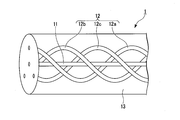
図1は、本発明の一実施形態による光ファイバセンサを示す斜視透視図である。また、図2は、本発明の一実施形態による光ファイバセンサの断面図である。これら図1,図2に示す通り、本実施形態の光ファイバセンサ1は、中心コア11、複数の外周コア12(外周コア12a~12c)、及びクラッド13を備えるマルチコアファイバの光ファイバセンサである。尚、クラッド13の外周面は、被覆(図示省略)に覆われていても良い。 <Configuration of optical fiber sensor>
FIG. 1 is a perspective perspective view showing an optical fiber sensor according to an embodiment of the present invention. FIG. 2 is a cross-sectional view of an optical fiber sensor according to an embodiment of the present invention. As shown in FIGS. 1 and 2, theoptical fiber sensor 1 of the present embodiment is a multi-core fiber optical fiber sensor including a central core 11, a plurality of outer cores 12 (outer cores 12 a to 12 c), and a clad 13. . The outer peripheral surface of the clad 13 may be covered with a coating (not shown).
図1は、本発明の一実施形態による光ファイバセンサを示す斜視透視図である。また、図2は、本発明の一実施形態による光ファイバセンサの断面図である。これら図1,図2に示す通り、本実施形態の光ファイバセンサ1は、中心コア11、複数の外周コア12(外周コア12a~12c)、及びクラッド13を備えるマルチコアファイバの光ファイバセンサである。尚、クラッド13の外周面は、被覆(図示省略)に覆われていても良い。 <Configuration of optical fiber sensor>
FIG. 1 is a perspective perspective view showing an optical fiber sensor according to an embodiment of the present invention. FIG. 2 is a cross-sectional view of an optical fiber sensor according to an embodiment of the present invention. As shown in FIGS. 1 and 2, the
中心コア11は、光ファイバセンサ1の中心に、光ファイバセンサ1の軸に対して平行に形成されたコアである。この中心コア11によって、光ファイバセンサ1の中心には、光ファイバセンサ1の長手方向に対して直線的な光路が形成される。中心コア11は、例えばゲルマニウム(Ge)(第1添加剤)を含む石英ガラスによって形成されている。また、中心コア11には、その全長に亘ってFBGが形成されている。尚、中心コア11の径は、例えば5~7[μm]の範囲に設定される。
The center core 11 is a core formed in the center of the optical fiber sensor 1 in parallel with the axis of the optical fiber sensor 1. By the central core 11, a linear optical path is formed in the center of the optical fiber sensor 1 with respect to the longitudinal direction of the optical fiber sensor 1. The central core 11 is made of, for example, quartz glass containing germanium (Ge) (first additive). Moreover, FBG is formed in the center core 11 over the full length. The diameter of the central core 11 is set in the range of 5 to 7 [μm], for example.
外周コア12は、中心コア11の周囲を螺旋状に取り巻くように形成されたコアである。本実施形態では、3つの外周コア12a~12cが、中心コア11に対して径方向で所定の距離d(図2参照)だけ離間し、長手方向に直交する断面において互いに角度θ(例えば、120°)の間隔をもって配置されている。これら外周コア12a~12cは、互いに角度θの間隔を維持しながら、中心コア11の周囲を螺旋状に取り巻くように光ファイバセンサ1の長手方向に延びている(図1参照)。これら外周コア12a~12cによって、光ファイバセンサ1内には、中心コア11を取り巻く螺旋状の3つの光路が形成される。
The outer peripheral core 12 is a core formed so as to spiral around the central core 11. In the present embodiment, the three outer cores 12a to 12c are separated from the central core 11 by a predetermined distance d (see FIG. 2) in the radial direction, and are mutually angle θ (for example, 120) in a cross section orthogonal to the longitudinal direction. Are arranged at intervals of °). These outer peripheral cores 12a to 12c extend in the longitudinal direction of the optical fiber sensor 1 so as to surround the central core 11 in a spiral shape while maintaining an interval of an angle θ (see FIG. 1). These outer peripheral cores 12a to 12c form three spiral optical paths surrounding the central core 11 in the optical fiber sensor 1.
複数の外周コア12a~12cは、中心コア11と同様に、例えばゲルマニウム(Ge)(第1添加剤)を含む石英ガラスによって形成されている。また、外周コア12a~12cには、その全長に亘ってFBGが形成されている。ここで、例えば中心コア11に添加されるゲルマニウムの濃度(モル濃度)と、外周コア12a~12cに添加されるゲルマニウムの濃度(モル濃度)との比率は、予め規定された関係(詳細は後述する)を満たすように設定される。外周コア12a~12cは、中心コア11と同径(或いは、ほぼ同じ径)であり、例えば5~7[μm]の範囲に設定される。
The plurality of outer peripheral cores 12a to 12c are formed of, for example, quartz glass containing germanium (Ge) (first additive), like the central core 11. Further, FBGs are formed over the entire length of the outer cores 12a to 12c. Here, for example, the ratio between the concentration (molar concentration) of germanium added to the central core 11 and the concentration (molar concentration) of germanium added to the outer cores 12a to 12c is a predetermined relationship (details will be described later). To meet). The outer peripheral cores 12a to 12c have the same diameter (or substantially the same diameter) as the central core 11, and are set in a range of 5 to 7 [μm], for example.
これは、屈折率を上げる作用を有する添加剤であるゲルマニウムの濃度を調整することで、中心コア11と外周コア12との実効屈折率の比率を調整して、中心コア11と外周コア12との光路長差を無くす(或いは、少なくする)ためである。尚、中心コア11及び外周コア12a~12cの実効屈折率の具体的な調整については後述する。
This is because the ratio of the effective refractive index between the central core 11 and the outer peripheral core 12 is adjusted by adjusting the concentration of germanium, which is an additive having the effect of increasing the refractive index. This is to eliminate (or reduce) the optical path length difference. The specific adjustment of the effective refractive index of the central core 11 and the outer cores 12a to 12c will be described later.
中心コア11と外周コア12a~12cとの距離dは、コア間のクロストーク、中心コア11と外周コア12a~12cとの光路長差、光ファイバセンサ1が屈曲したときの中心コア11と外周コア12a~12cとの歪量の差等を考慮して設定される。例えば、光ファイバセンサ1が、自身の形状(光ファイバセンサが取り付けられた構造物の形状)を測定する用途に用いられる場合、中心コア11と外周コア12a~12cとの距離が、例えば35[μm]程度であり、単位長さ当たりの外周コアの螺旋回数が、例えば50[ターン/m]程度であることが望ましい。
The distance d between the center core 11 and the outer cores 12a to 12c is the crosstalk between the cores, the optical path length difference between the center core 11 and the outer cores 12a to 12c, and the center core 11 and the outer periphery when the optical fiber sensor 1 is bent. It is set in consideration of the difference in distortion amount with the cores 12a to 12c. For example, when the optical fiber sensor 1 is used for measuring its own shape (the shape of a structure to which the optical fiber sensor is attached), the distance between the central core 11 and the outer cores 12a to 12c is, for example, 35 [ It is desirable that the number of spirals of the outer core per unit length is, for example, about 50 [turns / m].
クラッド13は、中心コア11及び外周コア12a~12cの周囲を覆う共通のクラッドである。クラッド13の外形は円柱形状である。中心コア11及び外周コア12a~12cは、共通のクラッド13に覆われていることから、中心コア11及び外周コア12a~12cは、クラッド13の内部に形成されている、と言うこともできる。このクラッド13は、例えば石英ガラスによって形成されている。
The clad 13 is a common clad covering the periphery of the central core 11 and the outer peripheral cores 12a to 12c. The outer shape of the clad 13 is a cylindrical shape. Since the central core 11 and the outer cores 12a to 12c are covered with the common clad 13, it can be said that the central core 11 and the outer cores 12a to 12c are formed inside the clad 13. The clad 13 is made of, for example, quartz glass.
〈実効屈折率の調整〉
次に、中心コア11及び外周コア12の実効屈折率の調整について詳細に説明する。図3は、本発明の一実施形態において中心コア及び外周コアの光路長差を説明するための図である。尚、以下では、光ファイバセンサ1の中心コア11と外周コア12(外周コア12a~12c)との距離をdとし、光ファイバセンサ1の単位長さ当たりの外周コア12の螺旋回数をfwとする。 <Adjusting the effective refractive index>
Next, adjustment of the effective refractive indexes of thecentral core 11 and the outer peripheral core 12 will be described in detail. FIG. 3 is a diagram for explaining the optical path length difference between the central core and the outer core in the embodiment of the present invention. In the following, the distance between the central core 11 of the optical fiber sensor 1 and the outer core 12 (outer cores 12a to 12c) is d, and the number of spirals of the outer core 12 per unit length of the optical fiber sensor 1 is fw. And
次に、中心コア11及び外周コア12の実効屈折率の調整について詳細に説明する。図3は、本発明の一実施形態において中心コア及び外周コアの光路長差を説明するための図である。尚、以下では、光ファイバセンサ1の中心コア11と外周コア12(外周コア12a~12c)との距離をdとし、光ファイバセンサ1の単位長さ当たりの外周コア12の螺旋回数をfwとする。 <Adjusting the effective refractive index>
Next, adjustment of the effective refractive indexes of the
図3において、符号P1が付された直線は中心コア11を表しており、符号P2が付された直線は外周コア12を表している。但し、図3においては、外周コア12の螺旋1周期に相当する中心コア11及び外周コア12のみを図示している。外周コア12の螺旋1周期に相当する中心コア11の光路長をL1とし、外周コア12の光路長をL2とすると、これらの関係は以下の(4)式で示される。
In FIG. 3, the straight line denoted by reference sign P 1 represents the central core 11, and the straight line denoted by reference sign P 2 represents the outer core 12. However, in FIG. 3, only the central core 11 and the outer peripheral core 12 corresponding to one spiral period of the outer peripheral core 12 are illustrated. When the optical path length of the central core 11, which corresponds to helix 1 cycle of the outer core 12 and L 1, the optical path length of the outer core 12 and L 2, these relationships are expressed by the following equation (4).

外周コア12は中心コア11の周囲を螺旋状に取り巻くように形成されているため、中心コア11及び外周コア12の実効屈折率が同じ場合には、外周コア12の光路長L2は、中心コア11の光路長L1よりも長くなる。具体的に、中心コア11と外周コア12との光路長差をAとし、外周コア12の長さをL1+Aと表すと、中心コア11と外周コア12との光路長差Aは以下の(5)式で表される。
Since the outer peripheral core 12 are formed so as to surround the periphery of the central core 11 helically, when the effective refractive index of the central core 11 and the outer peripheral core 12 are the same, the optical path length L 2 of the outer core 12, the center It becomes longer than the optical path length L 1 of the core 11. Specifically, if the optical path length difference between the central core 11 and the outer core 12 is A and the length of the outer core 12 is expressed as L 1 + A, the optical path length difference A between the central core 11 and the outer core 12 is as follows. It is represented by the formula (5).

また、上記(5)式で示される光路長差Aに相当する中心コア11の長さB(言い換えると、光路長差Aの光ファイバセンサ1の長手方向における長さB)は、以下の(6)式で示される。
Further, the length B of the central core 11 corresponding to the optical path length difference A expressed by the above equation (5) (in other words, the length B of the optical fiber sensor 1 in the longitudinal direction of the optical path length difference A) is as follows: 6) It is shown by a formula.

ここで、中心コア11の実効屈折率をne1とし、外周コア12の実効屈折率をne2とする。これら実効屈折率ne1,ne2が以下の(7)式を満たすとき、中心コア11と外周コア12との光路長差は、中心コア11及び外周コア12の実効屈折率が同じ場合の光路長差Aよりも小さくなる。つまり、以下の(7)式が満たされるように、中心コア11の実効屈折率ne1及び外周コア12の実効屈折率ne2を設定すれば、中心コア11及び外周コア12の実効屈折率が同じ場合に比べて光路長差を小さくすることができる。その結果として、長尺化した場合であっても全長に亘って高い測定精度を実現することが可能である。
Here, the effective refractive index of the central core 11 is set to ne1, and the effective refractive index of the outer core 12 is set to ne2 . When these effective refractive indexes n e1 and n e2 satisfy the following expression (7), the optical path length difference between the central core 11 and the outer core 12 is the optical path when the effective refractive indexes of the central core 11 and the outer core 12 are the same. It becomes smaller than the length difference A. That is, as the following equation (7) is satisfied, by setting the effective refractive index n e2 of the effective refractive index n e1 and the outer peripheral core 12 of the central core 11, the central core 11 and the effective refractive index of the outer core 12 Compared with the same case, the optical path length difference can be reduced. As a result, even when the length is increased, high measurement accuracy can be realized over the entire length.

次に、中心コア11及び複数の外周コア12に形成されるFBGについて検討する。中心コア11及び複数の外周コア12に形成されるFBGは、光ファイバセンサ1の長手方向に沿って同一の周期で形成される。上述の通り、外周コア12は中心コア11の周囲を螺旋状に取り巻くように形成されているため、中心コア11及び外周コア12の実効屈折率が同じ場合には、外周コア12の光路長L2は、中心コア11の光路長L1よりも長くなる。
Next, FBGs formed on the central core 11 and the plurality of outer peripheral cores 12 will be examined. The FBGs formed on the central core 11 and the plurality of outer peripheral cores 12 are formed with the same period along the longitudinal direction of the optical fiber sensor 1. As described above, since the outer core 12 is formed so as to surround the center core 11 in a spiral shape, the optical path length L of the outer core 12 is the same when the effective refractive indices of the center core 11 and the outer core 12 are the same. 2 is longer than the optical path length L 1 of the central core 11.
従って、外周コア12に形成されるFBGの周期(外周コア12に沿った周期)は、中心コア11に形成されるFBGの周期よりも長くなる。中心コア11に形成されたFBGのブラッグ波長をλ1とし、外周コア12に形成されたFBGのブラッグ波長をλ2とすると、これらの関係は以下の(8)式で示される。
Therefore, the cycle of the FBG formed on the outer core 12 (the cycle along the outer core 12) is longer than the cycle of the FBG formed on the center core 11. The Bragg wavelength of the FBG formed in the center core 11 and lambda 1, when the Bragg wavelength of the FBG formed on the outer periphery core 12 and lambda 2, these relationships are expressed by the following equation (8).

FBGのブラッグ波長λBは、光ファイバセンサ1に形成される屈折率の周期構造の1周期の長さをΛとし、実効屈折率をneとすると、以下の(9)式で示される。
Bragg wavelength lambda B of the FBG, the length of one period of the periodic structure of refractive index formed in the optical fiber sensor 1 and lambda, when the effective refractive index n e, is represented by the following equation (9).

中心コア11の実効屈折率ne1と外周コア12の実効屈折率ne2との比率を以下の(10)式に示す通りに設定すれば、中心コア11と外周コア12との光路長の比率がキャンセルされる。(10)式では、右辺が1よりも小さい値となるため、実効屈折率ne2の値は実効屈折率ne1の値よりも小さくなる。つまり、外周コア12の実効屈折率ne2は、中心コア11と外周コア12との光路長の比率に合うように、中心コア11の実効屈折率ne1よりも低く設定されている。これにより、中心コア11と外周コア12との光路長差、及び中心コア11と外周コア12とのブラッグ波長差を零に(或いは少なく)することができる。その結果として、光ファイバセンサ1を長尺化した場合であっても全長に亘って高い測定精度を実現することが可能である。
By setting the ratio of the effective refractive index n e2 of the effective refractive index n e1 and the outer core 12 of the central core 11 as shown in the following equation (10), the ratio of the optical path length between the center core 11 and the outer core 12 Will be cancelled. In (10), since the right side is a value smaller than 1, the value of the effective refractive index n e2 is smaller than the value of the effective refractive index n e1. That is, the effective refractive index n e2 of the outer core 12 is set lower than the effective refractive index n e1 of the center core 11 so as to match the ratio of the optical path lengths of the center core 11 and the outer core 12. Thereby, the optical path length difference between the central core 11 and the outer core 12 and the Bragg wavelength difference between the central core 11 and the outer core 12 can be made zero (or less). As a result, even when the length of the optical fiber sensor 1 is increased, it is possible to achieve high measurement accuracy over the entire length.

尚、例えば中心コア11及び外周コア12に添加されるゲルマニウムの比率を調整することで、上記(10)式に示される実効屈折率ne1,ne2の比率を実現することが可能である。具体的には、中心コア11に添加されるゲルマニウムのモル濃度m1と外周コア12に添加されるゲルマニウムのモル濃度m2との比率を、以下の(11)式を満たすように設定すれば良い。
For example, by adjusting the ratio of germanium added to the central core 11 and the outer peripheral core 12, it is possible to realize the ratio of the effective refractive indexes n e1 and n e2 shown in the above equation (10). Specifically, the ratio of the molar concentration m 2 of germanium is added to the molarity m 1 and the outer core 12 of germanium is added to the central core 11, it is set so as to satisfy the following expression (11) good.

〈光ファイバセンサの製造方法〉
次に、上述した光ファイバセンサの製造方法について説明する。図4は、本発明の一実施形態による光ファイバセンサの製造方法を示すフローチャートである。光ファイバセンサを製造する場合には、まず、実効屈折率が互いに異なっていて、所望の実効屈折率差を有する中心コア11のコア材及び外周コア12のコア材を形成する工程が行われる(工程S1)。なお、外周コア12のコア材は、1つであっても複数であってもよい。 <Manufacturing method of optical fiber sensor>
Next, a method for manufacturing the above-described optical fiber sensor will be described. FIG. 4 is a flowchart illustrating a method of manufacturing an optical fiber sensor according to an embodiment of the present invention. In the case of manufacturing an optical fiber sensor, first, a process of forming the core material of thecentral core 11 and the core material of the outer peripheral core 12 having different effective refractive indexes and having a desired effective refractive index difference is performed. Step S1). In addition, the core material of the outer periphery core 12 may be one or more.
次に、上述した光ファイバセンサの製造方法について説明する。図4は、本発明の一実施形態による光ファイバセンサの製造方法を示すフローチャートである。光ファイバセンサを製造する場合には、まず、実効屈折率が互いに異なっていて、所望の実効屈折率差を有する中心コア11のコア材及び外周コア12のコア材を形成する工程が行われる(工程S1)。なお、外周コア12のコア材は、1つであっても複数であってもよい。 <Manufacturing method of optical fiber sensor>
Next, a method for manufacturing the above-described optical fiber sensor will be described. FIG. 4 is a flowchart illustrating a method of manufacturing an optical fiber sensor according to an embodiment of the present invention. In the case of manufacturing an optical fiber sensor, first, a process of forming the core material of the
具体的には、屈折率を上げる作用を有する添加剤であるゲルマニウムが予め規定された濃度で添加された中心コア11のコア材と、中心コア11のコア材よりも低い濃度でゲルマニウムが添加された外周コア12のコア材とが形成される。例えば、中心コア11のコア材に添加されるゲルマニウムのモル濃度m1と外周コア12のコア材に添加されるゲルマニウムのモル濃度m2との比率は、例えば上述した(11)式を満たすように調整される。形成されたコア材をプリフォームアナライザで測定し、所望の実効屈折率差が得られているかを確認することが望ましい。
Specifically, the core material of the central core 11 to which germanium, which is an additive having an effect of increasing the refractive index, is added in a predetermined concentration, and germanium is added at a lower concentration than the core material of the central core 11 is added. The core material of the outer peripheral core 12 is formed. For example, the ratio between the molar concentration m 1 of germanium added to the core material of the central core 11 and the molar concentration m 2 of germanium added to the core material of the outer peripheral core 12 satisfies, for example, the above-described formula (11). Adjusted to It is desirable to measure the formed core material with a preform analyzer to confirm whether a desired effective refractive index difference is obtained.
次に、形成された中心コア11及び外周コア12のコア材をガラス管(キャピラリ)に挿入し、光ファイバセンサ1の母材を作成する工程が行われる(工程S2)。具体的には、中心コア11及び外周コア12のコア材が配置される位置に孔が形成されたキャピラリに、上記の工程S1で形成された中心コア11及び外周コア12のコア材をそれぞれ挿入し、溶融、延伸することで光ファイバの母材が作成される。尚、上記のキャピラリは、最終的には光ファイバセンサ1のクラッド13となる。
Next, a step of inserting the formed core material of the central core 11 and the outer peripheral core 12 into a glass tube (capillary) to create a base material of the optical fiber sensor 1 is performed (step S2). Specifically, the core materials of the central core 11 and the outer peripheral core 12 formed in the above-described step S1 are respectively inserted into the capillaries in which holes are formed at positions where the core materials of the central core 11 and the outer peripheral core 12 are arranged. Then, the base material of the optical fiber is created by melting and stretching. The capillary finally becomes the cladding 13 of the optical fiber sensor 1.
次いで、母材を回転させながら紡糸するとともに、紫外線(UV:UltraViolet)透過性を有する被覆材をクラッドの外側に形成する工程が行われる(工程S3)。具体的には、上記工程S2で作成された母材が紡糸機にセットされ、紡糸機によって母材を回転させながらの紡糸が行われる。このとき、紡糸によって得られた素線の外周、つまりクラッド13の外周に紫外線透過性を有する被覆材が形成される。ここで、母材を回転させながら紡糸を行うのは、外周コア12を螺旋状にするためである。また、クラッドの外周に紫外線透過性を有する被覆材を形成するのは、光ファイバを巻き取りながら紫外線を照射して中心コア11及び外周コア12にFBGを形成するためである。
Next, a process of spinning the base material while rotating the base material and forming a coating material having ultraviolet (UV) transparency on the outer side of the clad is performed (step S3). Specifically, the base material created in step S2 is set in a spinning machine, and spinning is performed while the base material is rotated by the spinning machine. At this time, a coating material having ultraviolet transparency is formed on the outer periphery of the strand obtained by spinning, that is, on the outer periphery of the clad 13. Here, the reason why spinning is performed while rotating the base material is to make the outer peripheral core 12 spiral. The reason why the coating material having ultraviolet transparency is formed on the outer periphery of the clad is to form FBGs on the central core 11 and the outer core 12 by irradiating ultraviolet rays while winding the optical fiber.
続いて、位相マスクを透過した紫外光を被覆材上から照射して、中心コア11及び外周コア12にFBGを形成する工程が行われる(工程S4)。中心コア11及び外周コア12にはゲルマニウムが添加されており、位相マスクを介して紫外光が中心コア11及び外周コア12に照射されることにより、中心コア11及び外周コア12に添加されたゲルマニウムが紫外光と反応する。これにより、屈折率が長手方向に周期的に変化する構造を有するFBGが中心コア11及び外周コア12に形成される。
Subsequently, an ultraviolet light transmitted through the phase mask is irradiated from above the coating material to form an FBG on the central core 11 and the outer core 12 (step S4). Germanium is added to the central core 11 and the outer peripheral core 12, and germanium added to the central core 11 and the outer peripheral core 12 is irradiated with ultraviolet light through the phase mask to the central core 11 and the outer peripheral core 12. Reacts with ultraviolet light. Thereby, FBGs having a structure in which the refractive index periodically changes in the longitudinal direction are formed on the central core 11 and the outer core 12.
ここで、中心コア11及び外周コア12の径が5~7[μm]程度であり、中心コア11と外周コア12との距離dが35[μm]であり、単位長さ当たりの外周コアの螺旋回数fwが50[ターン/m]である場合には、前述した(8)式から、中心コア11と外周コア12とのブラッグ波長の差は、1.55μm帯の波長域においては、95[pm]程度である。ゲルマニウムが添加されたコアの実効屈折率は、例えば約1.48であり、このブラッグ波長の差を補正するための外周コア12の実効屈折率差(中心コア11に対する外周コア12の実効屈折率差)は0.0001程度である。
Here, the diameters of the central core 11 and the outer peripheral core 12 are about 5 to 7 [μm], the distance d between the central core 11 and the outer peripheral core 12 is 35 [μm], and the outer core per unit length is When the number of spirals fw is 50 [turns / m], the difference between the Bragg wavelengths of the central core 11 and the outer core 12 from the above-described equation (8) is 1.55 μm in the wavelength range. It is about 95 [pm]. The effective refractive index of the core to which germanium is added is, for example, about 1.48, and the effective refractive index difference of the outer peripheral core 12 for correcting this Bragg wavelength difference (effective refractive index of the outer peripheral core 12 with respect to the central core 11). The difference is about 0.0001.
また、中心コア11と外周コア12との距離dが50[μm]であり、単位長さ当たりの外周コアの螺旋回数fwが100[ターン/m]である場合には、前述した(8)式から、中心コア11と外周コア12とのブラッグ波長の差は770[pm]となり大きくなる。このブラッグ波長の差を補正するためには、外周コア12の実効屈折率差(中心コア11に対する外周コア12の実効屈折率差)を0.0007程度にする必要がある。
The distance d between the center core 11 and the outer core 12 is 50 [[mu] m], if the spiral number f w of the outer core per unit length is 100 [turns / m] is the aforementioned (8 ), The difference in Bragg wavelength between the central core 11 and the outer core 12 is increased to 770 [pm]. In order to correct this difference in Bragg wavelength, the effective refractive index difference of the outer peripheral core 12 (effective refractive index difference of the outer peripheral core 12 with respect to the central core 11) needs to be about 0.0007.
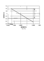
図5は、本発明の一実施形態による光ファイバセンサの特性の一例を示す図である。具体的に、図5は、中心コア11及び外周コア12の実効屈折率比(ne2/ne1)と、中心コア11及び外周コア12の光路長差との関係を示す図である。尚、図5においては、横軸に中心コア11及び外周コア12の実効屈折率比をとり、縦軸に中心コア11及び外周コア12の光路長差をとってある。
FIG. 5 is a diagram illustrating an example of characteristics of the optical fiber sensor according to the embodiment of the present invention. Specifically, FIG. 5 is a diagram illustrating the relationship between the effective refractive index ratio (n e2 / n e1 ) of the central core 11 and the outer core 12 and the optical path length difference between the central core 11 and the outer core 12. In FIG. 5, the horizontal axis represents the effective refractive index ratio between the central core 11 and the outer core 12, and the vertical axis represents the optical path length difference between the central core 11 and the outer core 12.
図5に示す特性は、中心コア11と外周コア12との距離dが35[μm]であり、光ファイバセンサ1の長手方向における外周コア12の螺旋1周期の長さが20[mm]であり、光ファイバセンサ1の全長が2[m]以上である場合のものである。図5に示す通り、中心コア11及び外周コア12の光路長差は、中心コア11及び外周コア12の実効屈折率比に比例する関係にある。
The characteristic shown in FIG. 5 is that the distance d between the central core 11 and the outer core 12 is 35 [μm], and the length of one spiral of the outer core 12 in the longitudinal direction of the optical fiber sensor 1 is 20 [mm]. Yes, the total length of the optical fiber sensor 1 is 2 [m] or more. As shown in FIG. 5, the optical path length difference between the central core 11 and the outer core 12 is proportional to the effective refractive index ratio between the central core 11 and the outer core 12.
ここで、図5に示す通り、中心コア11及び外周コア12の光路長差が図中のΔで示される範囲であれば、両者の実効屈折率が同じ場合の光路長差よりも両者の光路長差が小さくなる。このため、上記の場合には、中心コア11及び外周コア12の実効屈折率比(ne2/ne1)を、以下の式が満たされるように設定するのが望ましい。
0.99988<(ne2/ne1)<1 Here, as shown in FIG. 5, if the optical path length difference between thecentral core 11 and the outer core 12 is in the range indicated by Δ in the figure, the optical path length between the two is greater than the optical path length difference when both effective refractive indexes are the same. The difference in length is reduced. Therefore, in the above case, it is desirable to set the effective refractive index ratio (n e2 / n e1 ) of the central core 11 and the outer core 12 so that the following expression is satisfied.
0.99988 <(n e2 / n e1 ) <1
0.99988<(ne2/ne1)<1 Here, as shown in FIG. 5, if the optical path length difference between the
0.99988 <(n e2 / n e1 ) <1
以上の通り、本実施形態では、光ファイバセンサ1の中心コア11の実効屈折率ne1及び外周コアの実効屈折率ne2を、前述した(7)式を満たすように設定している。従って、中心コア11と外周コア12との光路長差を、中心コア11及び外周コア12の実効屈折率が同じ場合の光路長差Aよりも小さくすることができる。これにより、光ファイバセンサ1が長尺化した場合であっても全長に亘って高い測定精度を実現することが可能である。
As described above, in the present embodiment, the effective refractive index n e1 and effective refractive index n e2 of the outer core of the center core 11 of the optical fiber sensor 1 is set so as to satisfy the aforementioned equation (7). Therefore, the optical path length difference between the central core 11 and the outer peripheral core 12 can be made smaller than the optical path length difference A when the effective refractive indexes of the central core 11 and the outer peripheral core 12 are the same. Thereby, even when the optical fiber sensor 1 is elongated, it is possible to achieve high measurement accuracy over the entire length.
以上、本発明の実施形態について説明したが、本発明は上記実施形態に制限されることなく、本発明の範囲内で自由に変更が可能である。例えば、上述した実施形態では、屈折率を上げる作用を有する添加剤であるゲルマニウムの濃度を調整することで、外周コア12の実効屈折率を調整する例について説明した。しかしながら、中心コア11及び複数の外周コア12に添加するゲルマニウムの濃度を同じにし、例えばホウ素(B)やフッ素(F)等の屈折率を下げる作用を有する添加剤(第2添加剤)を複数の外周コア12a~12cに添加することにより、外周コア12a~12cの実効屈折率を調整するようにしても良い。
As mentioned above, although embodiment of this invention was described, this invention is not restrict | limited to the said embodiment, It can change freely within the scope of the present invention. For example, in the above-described embodiment, an example in which the effective refractive index of the outer peripheral core 12 is adjusted by adjusting the concentration of germanium, which is an additive having an effect of increasing the refractive index, has been described. However, the concentration of germanium added to the central core 11 and the plurality of outer peripheral cores 12 is the same, and a plurality of additives (second additives) having an action of lowering the refractive index, such as boron (B) and fluorine (F), are used. The effective refractive indexes of the outer peripheral cores 12a to 12c may be adjusted by adding them to the outer peripheral cores 12a to 12c.
また、中心コア11及び外周コア12の実効屈折率を調整する方法は、添加剤の濃度や種類を変える方法に限られない。例えば、中心コア11及び外周コア12の径を変えることによって実効屈折率を調整しても良い。或いは、例えば外周コア12a~12cの周囲に個別に低屈折率層を設けることによって実効屈折率を調整しても良い。
Further, the method of adjusting the effective refractive index of the central core 11 and the outer core 12 is not limited to the method of changing the concentration and type of the additive. For example, the effective refractive index may be adjusted by changing the diameters of the central core 11 and the outer peripheral core 12. Alternatively, for example, the effective refractive index may be adjusted by individually providing a low refractive index layer around the outer peripheral cores 12a to 12c.
また、上述した実施形態では、中心コア11の周囲を螺旋状に取り巻くように形成された外周コア12が、3つの外周コア12a~12cからなる例について説明した。しかしながら、外周コア12の数は任意で良く、例えば1つのみであっても良く、4つ以上であっても良い。例えば、外周コア12の数を6つとすると、光ファイバセンサ1の断面で見た場合に、中心コア11と合わせて最密充填配列にすることができるため望ましい。
In the above-described embodiment, the example in which the outer peripheral core 12 formed so as to surround the center core 11 in a spiral shape includes three outer peripheral cores 12a to 12c has been described. However, the number of outer peripheral cores 12 may be arbitrary, for example, only one may be sufficient and four or more may be sufficient. For example, when the number of the outer peripheral cores 12 is six, it is desirable that when viewed in the cross section of the optical fiber sensor 1, it is possible to form a close-packed arrangement together with the central core 11.
また、上述した実施形態では、理解を容易にするために、光ファイバセンサ1の中心コア11及び外周コア12a~12cに、光ファイバセンサ1の長手方向の全長に亘ってFBGが形成されている例について説明した。しかしながら、FBGは必ずしも光ファイバセンサ1の長手方向の全長に亘って形成されている必要は無く、長手方向の一部の領域にのみ形成されていても良い。
In the above-described embodiment, in order to facilitate understanding, the FBG is formed on the central core 11 and the outer cores 12a to 12c of the optical fiber sensor 1 over the entire length in the longitudinal direction of the optical fiber sensor 1. An example was described. However, the FBG does not necessarily have to be formed over the entire length in the longitudinal direction of the optical fiber sensor 1, and may be formed only in a partial region in the longitudinal direction.
また、中心コア11及び外周コア12a~12cに形成されるFBGは、一定周期のものであっても良く、周期が連続的に変化するもの(チャープグレーティング)であっても良い。また、光ファイバセンサ1の中心コア11及び外周コア12a~12cには、必ずしもFBGが形成されている必要は無く、FBGが形成されていなくとも良い。
Further, the FBGs formed on the central core 11 and the outer cores 12a to 12c may have a constant cycle or may have a continuously changing cycle (chirp grating). Further, the FBG is not necessarily formed on the central core 11 and the outer cores 12a to 12c of the optical fiber sensor 1, and the FBG may not be formed.
1…光ファイバセンサ、11…中心コア、12…外周コア、12a~12c…外周コア
DESCRIPTION OF SYMBOLS 1 ... Optical fiber sensor, 11 ... Central core, 12 ... Outer core, 12a-12c ... Outer core
Claims (6)
- 光ファイバの中心に形成された中心コアと、該中心コアの周囲を螺旋状に取り巻くように形成された少なくとも1つの外周コアとを備える光ファイバセンサであって、
前記中心コアと前記外周コアとの距離をdとし、単位長さ当たりの前記外周コアの螺旋回数をfwとすると、前記中心コアの実効屈折率ne1及び前記外周コアの実効屈折率ne2は、以下の(1)式を満たす、光ファイバセンサ。

The distance between the outer circumferential core and the center core is d, the spiral number of the peripheral core per unit length and f w, the effective refractive index of the central core n e1 and the outer circumferential core of the effective refractive index n e2 Is an optical fiber sensor that satisfies the following expression (1).
- 前記外周コアの実効屈折率ne2は、前記中心コアと前記外周コアとの光路長の比率に合うように、前記中心コアの実効屈折率ne1よりも低く設定されている、請求項1記載の光ファイバセンサ。 The effective refractive index ne2 of the outer peripheral core is set lower than the effective refractive index ne1 of the central core so as to match the ratio of the optical path lengths of the central core and the outer peripheral core. Fiber optic sensor.
- 前記中心コアの実効屈折率ne1と前記外周コアの実効屈折率ne2との比率は、以下の(2)式を満たすように設定されている、請求項1又は請求項2記載の光ファイバセンサ。

- 前記中心コアに添加される添加剤のモル濃度m1と前記外周コアに添加される添加剤のモル濃度m2との比率は、以下の(3)式を満たすように設定されている、請求項1から請求項3の何れか一項に記載の光ファイバセンサ。

- 前記中心コア及び前記外周コアには、同じ濃度のゲルマニウムが第1添加剤として添加されており、
前記外周コアには、屈折率を下げる作用を有する第2添加剤が添加されている、
請求項1から請求項4の何れか一項に記載の光ファイバセンサ。 In the central core and the outer peripheral core, germanium of the same concentration is added as a first additive,
A second additive having an action of lowering the refractive index is added to the outer core.
The optical fiber sensor as described in any one of Claims 1-4. - 長手方向の全長に亘り、或いは長手方向の一部の領域にFBGが形成されている、請求項1から請求項5の何れか一項に記載の光ファイバセンサ。 The optical fiber sensor according to any one of claims 1 to 5, wherein the FBG is formed over the entire length in the longitudinal direction or in a partial region in the longitudinal direction.
Priority Applications (3)
| Application Number | Priority Date | Filing Date | Title |
|---|---|---|---|
| CN201780085908.9A CN110268229B (en) | 2017-02-15 | 2017-12-08 | Optical fiber sensor |
| US16/485,096 US10883860B2 (en) | 2017-02-15 | 2017-12-08 | Optical fiber sensor |
| EP17897198.2A EP3584542B1 (en) | 2017-02-15 | 2017-12-08 | Optical fiber sensor |
Applications Claiming Priority (2)
| Application Number | Priority Date | Filing Date | Title |
|---|---|---|---|
| JP2017026270A JP6360929B1 (en) | 2017-02-15 | 2017-02-15 | Optical fiber sensor |
| JP2017-026270 | 2017-02-15 |
Publications (1)
| Publication Number | Publication Date |
|---|---|
| WO2018150699A1 true WO2018150699A1 (en) | 2018-08-23 |
Family
ID=62904921
Family Applications (1)
| Application Number | Title | Priority Date | Filing Date |
|---|---|---|---|
| PCT/JP2017/044173 WO2018150699A1 (en) | 2017-02-15 | 2017-12-08 | Optical fiber sensor |
Country Status (5)
| Country | Link |
|---|---|
| US (1) | US10883860B2 (en) |
| EP (1) | EP3584542B1 (en) |
| JP (1) | JP6360929B1 (en) |
| CN (1) | CN110268229B (en) |
| WO (1) | WO2018150699A1 (en) |
Families Citing this family (7)
| Publication number | Priority date | Publication date | Assignee | Title |
|---|---|---|---|---|
| JP6360929B1 (en) | 2017-02-15 | 2018-07-18 | 株式会社フジクラ | Optical fiber sensor |
| US10989865B2 (en) * | 2018-02-05 | 2021-04-27 | University Of Georgia Research Foundation, Inc | Stretchable fiber optic sensor |
| WO2020017565A1 (en) * | 2018-07-17 | 2020-01-23 | 株式会社フジクラ | Multi-core optical fiber and method of manufacturing multi-core optical fiber |
| KR102127897B1 (en) * | 2019-01-21 | 2020-06-29 | 한국광기술원 | Current Sensing System Having Multi-core Optical Fiber and Sensing Method Thereof |
| US20210282867A1 (en) * | 2020-03-16 | 2021-09-16 | St. Jude Medical International Holding S.À.R.L. | System and method for optical sensor reference frame alignment |
| CN112697231B (en) * | 2020-11-19 | 2021-10-26 | 电子科技大学 | Spirally arranged fiber bragg grating liquid level sensor |
| US11726257B2 (en) | 2021-03-05 | 2023-08-15 | Corning Incorporated | Multicore optical fiber |
Citations (27)
| Publication number | Priority date | Publication date | Assignee | Title |
|---|---|---|---|---|
| FR802503A (en) | 1935-03-05 | 1936-09-07 | Kampens Mek Verksted As | Screw press |
| JPS5232982B2 (en) | 1975-04-16 | 1977-08-25 | ||
| JPS5413931B2 (en) | 1974-06-07 | 1979-06-04 | ||
| JP2006003197A (en) * | 2004-06-17 | 2006-01-05 | Hitachi Cable Ltd | Optical cable for fbg sensor |
| US7317849B1 (en) | 2006-06-08 | 2008-01-08 | Institut National D'optique | Optical fiber sensor and method |
| JP2008175560A (en) * | 2007-01-16 | 2008-07-31 | Fujikura Ltd | Optical fiber sensor cable |
| KR20090039421A (en) | 2007-10-18 | 2009-04-22 | 세크론 주식회사 | Apparatus for molding substrates |
| KR20090039426A (en) | 2007-10-18 | 2009-04-22 | 흥성윈 주식회사 | Window frame for building |
| WO2009154216A1 (en) | 2008-06-20 | 2009-12-23 | 国立大学法人横浜国立大学 | Distributed optical-fiber hydrogen sensor, distributed optical-fiber hydrogen sensor for multipoint observation, hydrogen-sensitive film, and process for producing the same |
| BRPI0903197A2 (en) | 2008-05-06 | 2010-05-25 | Draka Comteq Bv | single mode fiber optic |
| JP2010517938A (en) | 2006-10-27 | 2010-05-27 | ジュセッペ・トリジャンテ | Compounds and methods for preventing hair loss |
| JP2010185729A (en) * | 2009-02-10 | 2010-08-26 | Fujikura Ltd | Distributed optical fiber pressure sensor cable |
| JP2010274663A (en) | 2010-08-27 | 2010-12-09 | Seiko Epson Corp | Liquid jetting apparatus, recorder, and electric field generating unit |
| US8116601B2 (en) | 2008-06-30 | 2012-02-14 | Intuitive Surgical Operations, Inc. | Fiber optic shape sensing |
| JP2012134673A (en) | 2010-12-20 | 2012-07-12 | Toshiba Corp | Directional coupler and coupling degree adjustment method |
| JP2013505663A (en) | 2009-09-22 | 2013-02-14 | サムスン エレクトロニクス カンパニー リミテッド | Method and system for idle timeout notification time for power saving operation of wireless network |
| US8630515B2 (en) | 2009-11-06 | 2014-01-14 | Baker Hughes Incorporated | Rotated single or multicore optical fiber |
| CA2920157A1 (en) | 2012-08-09 | 2014-02-13 | Corning Incorporated | Two-core optical fibers for distributed fiber sensors and systems |
| US8773650B2 (en) | 2009-09-18 | 2014-07-08 | Intuitive Surgical Operations, Inc. | Optical position and/or shape sensing |
| JP5595888B2 (en) | 2010-12-09 | 2014-09-24 | 株式会社フジクラ | Multi-core fiber |
| EP2806297A1 (en) | 2012-01-19 | 2014-11-26 | Fujikura Ltd. | Multi-core fiber |
| US9128234B2 (en) | 2011-08-08 | 2015-09-08 | Furukawa Electric Co., Ltd. | Multi-core optical fiber and optical transmission system |
| JP2015526585A (en) | 2012-08-31 | 2015-09-10 | ダウ グローバル テクノロジーズ エルエルシー | Heat-resistant polyolefin composition suitable as a film |
| US9417057B2 (en) | 2012-03-16 | 2016-08-16 | Koninklijke Philips N.V. | Optical sensing system for determining the position and/or shape of an associated object |
| JP2017026270A (en) | 2015-07-27 | 2017-02-02 | パナソニックIpマネジメント株式会社 | Dust collection system and dust collection method |
| JP2019085147A (en) | 2017-11-08 | 2019-06-06 | サーモス株式会社 | Bite valve and pouch for beverage container with bite valve |
| EP3584542A1 (en) | 2017-02-15 | 2019-12-25 | Fujikura Ltd. | Optical fiber sensor |
Family Cites Families (13)
| Publication number | Priority date | Publication date | Assignee | Title |
|---|---|---|---|---|
| US20070201793A1 (en) * | 2006-02-17 | 2007-08-30 | Charles Askins | Multi-core optical fiber and method of making and using same |
| JP5232982B2 (en) | 2008-08-28 | 2013-07-10 | 株式会社フジクラ | OPTICAL FIBER SENSOR HAVING OPTICAL MARKING PART FOR LOCATION OF OPTICAL FIBER, MEASURING METHOD OF OPTICAL FIBER SENSOR, AND OPTICAL FIBER SENSOR DEVICE |
| JP5678679B2 (en) * | 2010-01-22 | 2015-03-04 | 住友電気工業株式会社 | Multi-core fiber |
| CN101881858B (en) * | 2010-06-11 | 2012-07-11 | 哈尔滨工程大学 | Satellite-type helical multi-core fiber optical micro-tweezers capable of achieving rotation of small particles and preparation method thereof |
| WO2012029721A1 (en) * | 2010-08-30 | 2012-03-08 | 住友電気工業株式会社 | Multicore optical fiber |
| JP2012168453A (en) * | 2011-02-16 | 2012-09-06 | Hitachi Cable Ltd | Multi-core optical fiber, method of manufacturing multi-core optical fiber, and method of interconnecting multi-core optical fibers |
| JP2012211964A (en) | 2011-03-30 | 2012-11-01 | Fujikura Ltd | Multi-core fiber |
| US9031368B2 (en) * | 2012-04-26 | 2015-05-12 | Sumitomo Electric Industries, Ltd. | Multi-core optical fiber, multi-core optical fiber cable, and multi-core optical fiber transmission system |
| JP5413931B2 (en) | 2013-02-20 | 2014-02-12 | 株式会社フジクラ | OPTICAL FIBER SENSOR HAVING OPTICAL MARKING PART FOR LOCATION OF OPTICAL FIBER, MEASURING METHOD OF OPTICAL FIBER SENSOR, AND OPTICAL FIBER SENSOR DEVICE |
| WO2016122742A2 (en) * | 2014-11-11 | 2016-08-04 | Luna Innovations Incorporated | Optical fiber and method and apparatus for accurate fiber optic sensing under multiple stimuli |
| US10132614B2 (en) * | 2014-12-15 | 2018-11-20 | Intuitive Surgical Operations, Inc. | Dissimilar cores in multicore optical fiber for strain and temperature separation |
| US9885825B2 (en) * | 2016-04-18 | 2018-02-06 | Chiral Photonics, Inc. | Pitch reducing optical fiber array and multicore fiber comprising at least one chiral fiber grating |
| US10429584B2 (en) * | 2016-11-22 | 2019-10-01 | Lumentum Operations Llc | Rotary optical beam generator |
-
2017
- 2017-02-15 JP JP2017026270A patent/JP6360929B1/en active Active
- 2017-12-08 US US16/485,096 patent/US10883860B2/en active Active
- 2017-12-08 WO PCT/JP2017/044173 patent/WO2018150699A1/en unknown
- 2017-12-08 EP EP17897198.2A patent/EP3584542B1/en active Active
- 2017-12-08 CN CN201780085908.9A patent/CN110268229B/en active Active
Patent Citations (36)
| Publication number | Priority date | Publication date | Assignee | Title |
|---|---|---|---|---|
| FR802503A (en) | 1935-03-05 | 1936-09-07 | Kampens Mek Verksted As | Screw press |
| JPS5413931B2 (en) | 1974-06-07 | 1979-06-04 | ||
| JPS5232982B2 (en) | 1975-04-16 | 1977-08-25 | ||
| JP2006003197A (en) * | 2004-06-17 | 2006-01-05 | Hitachi Cable Ltd | Optical cable for fbg sensor |
| US7317849B1 (en) | 2006-06-08 | 2008-01-08 | Institut National D'optique | Optical fiber sensor and method |
| JP2010517938A (en) | 2006-10-27 | 2010-05-27 | ジュセッペ・トリジャンテ | Compounds and methods for preventing hair loss |
| JP2008175560A (en) * | 2007-01-16 | 2008-07-31 | Fujikura Ltd | Optical fiber sensor cable |
| KR20090039421A (en) | 2007-10-18 | 2009-04-22 | 세크론 주식회사 | Apparatus for molding substrates |
| KR20090039426A (en) | 2007-10-18 | 2009-04-22 | 흥성윈 주식회사 | Window frame for building |
| PL2116877T3 (en) | 2008-05-06 | 2012-04-30 | Draka Comteq Bv | Single mode optical fiber |
| DK2116878T3 (en) | 2008-05-06 | 2012-03-05 | Draka Comteq Bv | Bending-resistant optical single-mode fiber |
| BRPI0903858A2 (en) | 2008-05-06 | 2010-07-20 | Draka Comteq Bv | single-mode optical fiber insensitive to curvature |
| KR101614943B1 (en) | 2008-05-06 | 2016-04-22 | 드라카 콤텍 비.브이. | Single mode optical fiber |
| RU2009117161A (en) | 2008-05-06 | 2010-11-10 | Драка Комтек Б.В. (Nl) | SINGLE-MODE OPTICAL FIBER |
| RU2009117160A (en) | 2008-05-06 | 2010-11-20 | Драка Комтек Б.В. (Nl) | SINGLE-MODE OPTICAL FIBER NON-BENDABLE |
| BRPI0903197A2 (en) | 2008-05-06 | 2010-05-25 | Draka Comteq Bv | single mode fiber optic |
| WO2009154216A1 (en) | 2008-06-20 | 2009-12-23 | 国立大学法人横浜国立大学 | Distributed optical-fiber hydrogen sensor, distributed optical-fiber hydrogen sensor for multipoint observation, hydrogen-sensitive film, and process for producing the same |
| US8116601B2 (en) | 2008-06-30 | 2012-02-14 | Intuitive Surgical Operations, Inc. | Fiber optic shape sensing |
| JP2010185729A (en) * | 2009-02-10 | 2010-08-26 | Fujikura Ltd | Distributed optical fiber pressure sensor cable |
| US8773650B2 (en) | 2009-09-18 | 2014-07-08 | Intuitive Surgical Operations, Inc. | Optical position and/or shape sensing |
| JP2013505663A (en) | 2009-09-22 | 2013-02-14 | サムスン エレクトロニクス カンパニー リミテッド | Method and system for idle timeout notification time for power saving operation of wireless network |
| US8630515B2 (en) | 2009-11-06 | 2014-01-14 | Baker Hughes Incorporated | Rotated single or multicore optical fiber |
| JP2010274663A (en) | 2010-08-27 | 2010-12-09 | Seiko Epson Corp | Liquid jetting apparatus, recorder, and electric field generating unit |
| JP5595888B2 (en) | 2010-12-09 | 2014-09-24 | 株式会社フジクラ | Multi-core fiber |
| JP2012134673A (en) | 2010-12-20 | 2012-07-12 | Toshiba Corp | Directional coupler and coupling degree adjustment method |
| US9128234B2 (en) | 2011-08-08 | 2015-09-08 | Furukawa Electric Co., Ltd. | Multi-core optical fiber and optical transmission system |
| JP5916525B2 (en) | 2012-01-19 | 2016-05-11 | 株式会社フジクラ | Multi-core fiber |
| EP2806297B1 (en) | 2012-01-19 | 2019-09-25 | Fujikura Ltd. | Multi-core fiber |
| EP2806297A1 (en) | 2012-01-19 | 2014-11-26 | Fujikura Ltd. | Multi-core fiber |
| US9417057B2 (en) | 2012-03-16 | 2016-08-16 | Koninklijke Philips N.V. | Optical sensing system for determining the position and/or shape of an associated object |
| US20170089834A1 (en) | 2012-08-09 | 2017-03-30 | Corning Incorporated | Two-core optical fibers for distributed fiber sensors and systems |
| CA2920157A1 (en) | 2012-08-09 | 2014-02-13 | Corning Incorporated | Two-core optical fibers for distributed fiber sensors and systems |
| JP2015526585A (en) | 2012-08-31 | 2015-09-10 | ダウ グローバル テクノロジーズ エルエルシー | Heat-resistant polyolefin composition suitable as a film |
| JP2017026270A (en) | 2015-07-27 | 2017-02-02 | パナソニックIpマネジメント株式会社 | Dust collection system and dust collection method |
| EP3584542A1 (en) | 2017-02-15 | 2019-12-25 | Fujikura Ltd. | Optical fiber sensor |
| JP2019085147A (en) | 2017-11-08 | 2019-06-06 | サーモス株式会社 | Bite valve and pouch for beverage container with bite valve |
Non-Patent Citations (3)
| Title |
|---|
| "LUNA Fiber Optic Shape Sensing", 21 June 2013, LUNA INNOVATIONS INCORPORATED |
| P. S. WESTBROOK ET AL.: "Integrated optical fiber shape senor modules based on twisted multicore fiber grating arrays", PROC. SPIE 8938, OPTICAL FIBERS AND SENSORS FOR MEDICAL DIAGNOSTICS AND TREATMENT APPLICATIONS XIV, vol. XIV, 20 February 2014 (2014-02-20), pages 89380H |
| See also references of EP3584542A4 |
Also Published As
| Publication number | Publication date |
|---|---|
| US20200041313A1 (en) | 2020-02-06 |
| JP2018132421A (en) | 2018-08-23 |
| US10883860B2 (en) | 2021-01-05 |
| EP3584542B1 (en) | 2022-08-17 |
| EP3584542A4 (en) | 2020-12-02 |
| JP6360929B1 (en) | 2018-07-18 |
| CN110268229B (en) | 2021-09-28 |
| CN110268229A (en) | 2019-09-20 |
| EP3584542A1 (en) | 2019-12-25 |
Similar Documents
| Publication | Publication Date | Title |
|---|---|---|
| WO2018150699A1 (en) | Optical fiber sensor | |
| US20070201793A1 (en) | Multi-core optical fiber and method of making and using same | |
| EP3234667B1 (en) | Dissimilar cores in multicore optical fiber for strain and temperature separation | |
| EP2110652B1 (en) | Multi-core fiber grating sensor | |
| US11473943B2 (en) | Optical fiber sensor | |
| JP6226905B2 (en) | Multi-core optical fiber and method for manufacturing multi-core optical fiber | |
| US20100166358A1 (en) | Dual Fiber Grating and Methods of Making and Using Same | |
| AU2013360255A1 (en) | Hydrogen resistant downhole optical fiber sensing | |
| JP6722368B2 (en) | Multi-core optical fiber | |
| MX2012006300A (en) | Bend insensitive optical fiber with improved hydrogen resistance. | |
| Chen et al. | Temperature insensitive bending sensor based on in-line Mach-Zehnder interferometer | |
| Askins et al. | Inscription of fiber Bragg gratings in multicore fiber | |
| Vincent et al. | Curvature and shape sensing for continuum robotics using draw tower gratings in multi core fiber | |
| Makovetskii et al. | A study of the optical properties of a multimode silica optical fiber with a reflective shell from a fluorinated thermoplastic polymer | |
| KR20220102916A (en) | Double-clad fiber Mach-Zehnder interferometer based on long-period fiber grating and apparatus and method for simultaneous measuring of bending and temperature insensitive to strain using thereof | |
| KR20040027737A (en) | Long period grating with long length and Fiber optic sensor for measuring the weight |
Legal Events
| Date | Code | Title | Description |
|---|---|---|---|
| 121 | Ep: the epo has been informed by wipo that ep was designated in this application |
Ref document number: 17897198 Country of ref document: EP Kind code of ref document: A1 |
|
| NENP | Non-entry into the national phase |
Ref country code: DE |
|
| ENP | Entry into the national phase |
Ref document number: 2017897198 Country of ref document: EP Effective date: 20190916 |