EP2806297A1 - Multi-core fiber - Google Patents
Multi-core fiber Download PDFInfo
- Publication number
- EP2806297A1 EP2806297A1 EP20120866305 EP12866305A EP2806297A1 EP 2806297 A1 EP2806297 A1 EP 2806297A1 EP 20120866305 EP20120866305 EP 20120866305 EP 12866305 A EP12866305 A EP 12866305A EP 2806297 A1 EP2806297 A1 EP 2806297A1
- Authority
- EP
- European Patent Office
- Prior art keywords
- cores
- core
- refractive index
- clad
- core fiber
- Prior art date
- Legal status (The legal status is an assumption and is not a legal conclusion. Google has not performed a legal analysis and makes no representation as to the accuracy of the status listed.)
- Granted
Links
- 239000000835 fiber Substances 0.000 title claims abstract description 178
- 230000001902 propagating effect Effects 0.000 claims abstract description 27
- 230000014509 gene expression Effects 0.000 claims description 50
- 238000005452 bending Methods 0.000 description 107
- 239000013307 optical fiber Substances 0.000 description 67
- 239000011295 pitch Substances 0.000 description 56
- 238000010586 diagram Methods 0.000 description 41
- 238000000034 method Methods 0.000 description 18
- 238000009826 distribution Methods 0.000 description 12
- 239000011521 glass Substances 0.000 description 10
- 230000000644 propagated effect Effects 0.000 description 9
- 230000003287 optical effect Effects 0.000 description 8
- 238000004891 communication Methods 0.000 description 7
- 239000011241 protective layer Substances 0.000 description 7
- 238000013461 design Methods 0.000 description 5
- 239000006185 dispersion Substances 0.000 description 5
- 230000004048 modification Effects 0.000 description 5
- 238000012986 modification Methods 0.000 description 5
- 238000011835 investigation Methods 0.000 description 4
- 239000000463 material Substances 0.000 description 4
- 230000005540 biological transmission Effects 0.000 description 2
- 230000000694 effects Effects 0.000 description 2
- 238000004519 manufacturing process Methods 0.000 description 2
- 230000009467 reduction Effects 0.000 description 2
- VYPSYNLAJGMNEJ-UHFFFAOYSA-N Silicium dioxide Chemical compound O=[Si]=O VYPSYNLAJGMNEJ-UHFFFAOYSA-N 0.000 description 1
- 230000004888 barrier function Effects 0.000 description 1
- 230000008859 change Effects 0.000 description 1
- 230000000052 comparative effect Effects 0.000 description 1
- 238000006073 displacement reaction Methods 0.000 description 1
- 238000007526 fusion splicing Methods 0.000 description 1
- 239000004038 photonic crystal Substances 0.000 description 1
- 235000012239 silicon dioxide Nutrition 0.000 description 1
- 230000007480 spreading Effects 0.000 description 1
- 238000003892 spreading Methods 0.000 description 1
- 239000011800 void material Substances 0.000 description 1
Images


Classifications
-
- G—PHYSICS
- G02—OPTICS
- G02B—OPTICAL ELEMENTS, SYSTEMS OR APPARATUS
- G02B6/00—Light guides; Structural details of arrangements comprising light guides and other optical elements, e.g. couplings
- G02B6/02—Optical fibres with cladding with or without a coating
- G02B6/02042—Multicore optical fibres
-
- G—PHYSICS
- G02—OPTICS
- G02B—OPTICAL ELEMENTS, SYSTEMS OR APPARATUS
- G02B6/00—Light guides; Structural details of arrangements comprising light guides and other optical elements, e.g. couplings
- G02B6/02—Optical fibres with cladding with or without a coating
- G02B6/036—Optical fibres with cladding with or without a coating core or cladding comprising multiple layers
- G02B6/03616—Optical fibres characterised both by the number of different refractive index layers around the central core segment, i.e. around the innermost high index core layer, and their relative refractive index difference
- G02B6/03638—Optical fibres characterised both by the number of different refractive index layers around the central core segment, i.e. around the innermost high index core layer, and their relative refractive index difference having 3 layers only
- G02B6/0365—Optical fibres characterised both by the number of different refractive index layers around the central core segment, i.e. around the innermost high index core layer, and their relative refractive index difference having 3 layers only arranged - - +
-
- G—PHYSICS
- G02—OPTICS
- G02B—OPTICAL ELEMENTS, SYSTEMS OR APPARATUS
- G02B6/00—Light guides; Structural details of arrangements comprising light guides and other optical elements, e.g. couplings
- G02B6/02—Optical fibres with cladding with or without a coating
- G02B6/036—Optical fibres with cladding with or without a coating core or cladding comprising multiple layers
Definitions
- the refractive index difference between the first clad 13 and the clad 20 is often nearly zero.
- the refractive index difference is appropriately set to positive and negative values in order to adjust the wavelength dispersion characteristics.
- the refractive index n 2 of the first clad 13 is set similar to the refractive index n 4 of the clad 20.
- the refractive indices n 2 of the first clads 13 are equal to each other in the core elements 11a and 12a
- the refractive indices n 3 of the second clads 14 are equal to each other in the core elements 11a and 12a.
- the refractive index n 2 of the first clad 13 in the core element 11a and the refractive index n 2 of the first clad 13 in the core element 12a may have different refractive indices from each other depending on the effective refractive index difference ⁇ n eff between the core 11 and the core 12.
- the numbers of the core elements 11a and 12a according to the second embodiment are increased, and the number of the core elements is 12 in total.
- the inter-center pitches between the cores 11 and 12 are equal to each other, and the cores 11 and 12 are disposed in a regular dodecagon in which the center is aligned with the axis of the clad 20. It is noted that it can be thought as well that the cores 11 and 12 are annularly disposed in which the center is aligned with the axis of the clad 20.
- the average fusion splicing loss of this multi-core fiber was significantly small as 0.09 dB. As described above, it was shown that the splicing loss was small in the case where a plurality of the multi-core fibers was connected because the multi-core fiber according to the example had a small mode field diameter difference between the cores.
- multi-core fibers similar to the multi-core fibers in the third example to the fifth example were prepared as core pitches were 33 ⁇ m.
- the parameters of the multi-core fiber according to a ninth example were similarly set to the parameters of the third example
- the parameters of the multi-core fiber according to a tenth example were similarly set to the parameters of the fourth embodiment
- the parameters of the multi-core fiber according to an eleventh example were similarly set to the parameters of the fifth example.
Landscapes
- Physics & Mathematics (AREA)
- General Physics & Mathematics (AREA)
- Optics & Photonics (AREA)
- Optical Integrated Circuits (AREA)
- Lasers (AREA)
- Optical Fibers, Optical Fiber Cores, And Optical Fiber Bundles (AREA)
- Optical Communication System (AREA)
Abstract
Description
- The present invention relates to a multi-core fiber that can suppress the crosstalk between cores adjacent to each other even in the case where the multi-core fiber is nonlinearly disposed while suppressing splicing losses.
- Currently, optical fibers used for optical fiber communication systems which are generally spreading adopt a structure in which an outer periphery of one core is surrounded by a clad, and information is transmitted when an optical signal propagates in this core. Further, as the optical fiber communication systems spread, the amount of information to be transmitted is dramatically increasing in recent years. Following an increase in the amount of information to be transmitted, the optical fiber communication systems use several tens or several hundreds of multiple optical fibers to perform long-distance optical communication of a large volume.
- It is known that, to reduce the number of optical fibers in such an optical fiber communication system, a plurality of signals are transmitted by means of light propagating in respective cores using a multi-core fiber in which outer peripheries of a plurality of cores are surrounded by one clad.
- Non-Patent Document 1 below describes such a multi-core fiber. In this multi-core fiber, a plurality of cores are arranged in one clad. For an example of this multi-core fiber, an example is taken in which a single core is disposed in the center of a clad and six cores are disposed around the core disposed in the center. Such a configuration is a structure in which cores can be closely packed, so that a large number of cores can be disposed with respect to the specific outer diameter of the clad. However, as is pointed out in Non-Patent Document 1, in the multi-core fiber, optical signals propagating in respective cores interfere each other, and noise is superimposed on the optical signals propagating in the respective cores in some case. Therefore, Non-Patent Document 1 describes a method for reducing crosstalk in which refractive index differences are changed between the clad and cores adjacent to each other to vary the propagation constants (the wave guide conditions) of the cores adjacent to each other. Moreover, Patent Document 1 below describes a method for varying propagation constants from each other in which refractive index differences or the diameters of cores, for example, are varied from each other. Propagation constants are varied between the cores adjacent to each other as decried above, so that crosstalk can be reduced.
- However, even in the multi-core fiber in which the propagation constants of the cores adjacent to each other are different as in Non-Patent Document 1 and Patent Document 1, in the case where the multi-core fiber is bent in a specific bending diameter, one of the cores adjacent to each other is located on the inner side of the arc and the other is located on the outer side of the arc, which sometimes causes the propagation constants of the cores to be matched with each other. Non-Patent
Document 2 below describes a multi-core fiber in which an inter-center pitch between cores is set to 30 µm, the MFDs (mode field diameters) of the cores are set to 8.1 µm and 9.4 µm, respectively, and a propagation constant difference is given between the cores. Even in this case, the propagation constants of the cores are matched with each other to degrade crosstalk in the case where the bending radius of the multi-core fiber is about 100 mm. - An optical fiber accommodated in a cable is in a state in which a bend corresponding to a certain radius is applied to the optical fiber. Although the bending radius is greatly different depending on cable designs, the probability of fatigue failure is increased to cause an issue in durability, and bending losses are increased to reduce communication quality at a banding radius smaller than 100 mm. From the viewpoints, such a design is not generally provided in which the bending radius is smaller than a bending radius of 100 mm. Such a bend whose radius is below 100 mm is sometimes applied to input/output ends, branch portions, and the like because of accommodating excessive lengths. However, the lengths are limited as compared with lengths in cable portions, and crosstalk rarely occurs on input/output ends, branch portions, and the like.
-
- Non-Patent Document 1: Masanori KOSHIBA "Heterogeneous multi-core fibers: proposal and design principle" IEICE Electronics Express, Vol.6, No.2, 98-103
- Non-Patent Document 2: Crosstalk Variation of Multi-core Fiber Due to Fiber Bend:ECOC2010, We.8.F6
- Patent Document 1: International Publication No.
WO2010/0388863 - An optical fiber is generally disposed linearly as well as disposed nonlinearly in some cases. For example, in a cable having a plurality of optical fibers accommodated in the cable, the optical fibers are often spirally disposed in the cable. In this case, even in the case where the propagation constants of cores adjacent to each other are varied as in Non-Patent Document 1 and Patent Document 1 described above, the optical propagation constants of the cores adjacent to each other are sometimes matched with each other as described in
Non-Patent Document 2 above. The state repeatedly occurs or continues for a long time, and the crosstalk between the cores adjacent to each other is prone to deteriorate. - In the case where a multi-core fiber is nonlinearly disposed as described above, in order to suppress the crosstalk between cores adjacent to each other, such a configuration may be performed in which the mode field diameter (MFD) of light propagating through cores is greatly changed to considerably alter the propagation constants of the cores adjacent to each other. However, in the case where the mode field diameter of light propagating through cores is greatly changed as described above, in connecting a plurality of multi-core fibers, attenuation caused by connection becomes considerably large when cores whose mode field diameters are different from each other are connected to each other.
- Therefore, it is an object of the present invention to provide a multi-core fiber that can suppress the crosstalk between cores adjacent to each other even in the case where the multi-core fiber is nonlinearly disposed while suppressing splicing losses.
- The present inventors dedicatedly conducted investigations in order to achieve the objects. In the case where a multi-core fiber is bent, the crosstalk between cores adjacent to each other sharply deteriorates at a certain bending radius specific to the multi-core fiber. Therefore, the present inventors considered that when the bending radius at which this crosstalk is at a peak is smaller than the minimum bending radius under a general use environment of an optical fiber, the crosstalk between cores adjacent to each other can be suppressed without the necessity to considerably change the mode field diameter (MFD) of light propagating through cores adjacent to each other.
- As described above, when an optical fiber is bent at a small bending radius, the probability of fatigue failure is increased and the attenuation of light propagating through a core due to the bend becomes large, for example. Because of the reasons, the minimum bending radius of an optical fiber in a cable is generally set to 100 mm. Therefore, it is considered that when the bending radius of an optical fiber at which crosstalk is at a peak is smaller than a bending radius of 100 mm, which is the minimum bending radius under a general use environment of an optical fiber, crosstalk can be sufficiently suppressed under a general use environment of a multi-core fiber.
- Moreover, a general core pitch (an inter-center pitch between cores adjacent to each other) in a multi-core fiber generally ranges from 30 µm to 50 µm from the viewpoint of preventing the crosstalk between cores adjacent to each other and from the viewpoint of preventing the outer diameter of a clad from becoming too large. The bending radius of an optical fiber at which crosstalk is at a peak can be generally determined from the effective refractive index difference between cores adjacent to each other and the core pitch between the cores. Therefore, the present inventors considered that it would work in which the effective refractive index difference between cores adjacent to each other is set in such a way that the bending radius of an optical fiber at which crosstalk is at a peak is a bending radius smaller than a bending radius of 100 mm, which is the minimum bending radius under a general use environment of an optical fiber, in a range in which the core pitch ranges from 30 µm to 50 µm.
- As a result of dedicated investigations, the present inventors found that the effective refractive index difference between cores adjacent to each other is a predetermined value or more, which is changed according to a core pitch, in order that the bending radius of an optical fiber at which crosstalk is at a peak is made smaller than a bending radius of 100 mm, in a range in which the core pitch ranges from 30 µm to 50 µm. Thus, the present inventors thought that the objects can be achieved when the effective refractive index difference between cores adjacent to each other in a multi-core fiber is made greater than this predetermined value.
- However, it was revealed that even though the effective refractive index difference between cores adjacent to each other is simply made greater than this predetermined value to design a multi-core fiber, it is sometimes difficult to dispose cores as similar to a previously existing multi-core fiber in an allowable range of the radius of a core through which a fundamental mode can propagate and the refractive index difference between cores and a clad.
- Therefore, the present inventors further dedicatedly conducted investigations to achieve the present invention.
- Namely, a multi-core fiber according to the present invention includes: an even number of six or more of cores; and a clad surrounding outer circumferential surfaces of the cores. The even number of cores is formed of two types of cores between which an effective refractive index difference in a fundamental mode is different. In the even number of cores, the two types of cores are alternately disposed at regular spacings, and the cores are annularly disposed at an interior angle formed of lines connecting centers of the cores adjacent to each other, the interior angle being greater than an angle of 90°. A difference in a mode field diameter of light propagating through the cores is 1 µm or less. An expression is satisfied:

- According to such a multi-core fiber, the difference in the mode field diameter of light propagating through the cores is 1 µm or less, so that splicing losses can be made smaller even in the case where different types of cores are connected to each other when a plurality of the multi-core fibers is connected.
- Moreover, as a result of dedicated investigations conducted by the present inventors, it was found that in order that the bending radius of an optical fiber at which crosstalk is at a peak is made smaller than a bending radius of 100 mm, the effective refractive index difference between cores adjacent to each other is a predetermined value or more, which is changed according to a core pitch, as described above. More specifically, it was found that the following expression is satisfied:

- From the result found as described above, the present inventors reached the conclusion that the objects can be achieved by such a multi-core fiber in a configuration in which an even number of six or more of cores are formed of two types of cores between which the effective refractive index difference Δneff is a predetermined value or more and 0.002 or less derived from the expression changed according to the core pitch and the two types of the cores are annularly disposed in which an interior angle formed of lines connecting the centers of two cores adjacent to each other is greater than an angle of 90°. According to such a multi-core fiber, the bending radius of the optical fiber at which crosstalk is at a peak can be made smaller than a bending radius of 100 mm, which is the minimum bending radius under a general use environment of an optical fiber.
- Thus, according to such a multi-core fiber, the mode field diameter of light propagating through the cores adjacent to each other is not changed so much, crosstalk can be suppressed in the general use state while splicing losses can be suppressed.
- Moreover, preferably, the inter-center pitch and the effective refractive index difference further satisfy an expression:

- By satisfying the conditions, the bending radius of the optical fiber at which crosstalk is at a peak can be 70 mm or less that is much smaller than a bending radius of 100 mm, which is the minimum bending radius under a general use environment of an optical fiber.
- Furthermore, the inter-center pitch and the effective refractive index difference may further satisfy an expression:

- In addition, preferably, when the number of cores is n, the cores are disposed in an n-sided regular polygon.
- The fact that the cores are disposed as described above can be thought as well that the cores are annularly disposed. The cores are disposed in this manner, so that the influence exerted from the adjacent core is made equal between the cores, and the cores can maintain the uniformity of light propagating through the cores.
- Moreover, preferably, the cores are disposed in a regular hexagon.
- For a method of manufacture of a multi-core optical fiber, a stack-and-draw method and a boring method are known. The stack-and-draw method is a method also for use in manufacture of a photonic crystal fiber. In this method, cores are disposed in which cylindrical glass rods including a region to be a core are combined in a close-packed hexagonal lattice. The combined glass rods to be these cores are inserted into a glass tube and solidified to obtain a multi-core fiber base material, and this base material is drawn to obtain a multi-core fiber. In the stack-and-draw method, such multi-core fibers can be easily produced including a seven-core multi-core fiber in which six cores are disposed in a hexagon around the center core and a 19-core multi-core fiber in which 12 cores are disposed in a hexagon further around the outer circumference of a seven-core multi-core fiber. For example, in the stack-and-draw method, when a glass rod with no core is used instead of a glass rod to be a core disposed in the center part and 12 glass rods with cores are disposed around the glass rod, such a multi-core fiber can be implemented in which 12 cores are annularly disposed in a hexagon. Also in the case of multi-core fibers having cores whose number is a multiple of six greater than 12 such as 18 cores and 24 cores, these multi-core fibers can be similarly manufactured. Thus, in the case where cores are disposed in a regular hexagon, multi-core fibers including a larger number of cores can be easily manufactured by existing methods.
- On the other hand, a multi-core fiber can be implemented by the boring method in which a hole is bored in a glass base material prepared beforehand using a drill, for example, a cylindrical glass rod including a region to be a core is inserted into the hole, and a void is squeezed. In the boring method, since cores can be disposed at given locations in a glass base material, the method is suited to implement cores annularly disposed.
- Moreover, preferably, the multi-core fiber further includes: a first clad surrounding outer circumferential surfaces of the cores; and a second clad surrounding an outer circumferential surface of the first clad, an outer circumferential surface of the second clad being surrounded by the clad. All of expressions are satisfied:


- In the case where the core, the first clad, and the second clad are considered to be a core element, the core is surrounded by the first clad having the refractive index n2 smaller than the refractive indices n1-1 and n1-2 of the cores, and the first clad is surrounded by the second clad having the refractive index n3 smaller than the refractive index n2 of the first clad. Thus, in the case where the core elements are seen from the viewpoint of the refractive indices, the core elements have a trench structure. In the multi-core fiber in the structure, since the refractive index n3 of the second clad is smaller than the refractive index n2 of the first clad for light propagating through the core, so that light is more properly confined in the core, and it is suppressed that light leaks out of the core elements. Accordingly, according to such a multi-core fiber, the crosstalk between cores can be further reduced.
- As described above, according to the present invention, there is provided a multi-core fiber that can suppress the crosstalk between cores adjacent to each other even in the case where the multi-core fiber is nonlinearly disposed while suppressing splicing losses.
-
-
FIGS. 1A and 1B are diagrams of a multi-core fiber according to a first embodiment of the present invention; -
FIG. 2 is a diagram of the distribution of the effective refractive index difference between cores for individual effective refractive index differences in the case where a core pitch in the multi-core fiber and a bending radius at which crosstalk is at a peak are determined; -
FIG. 3 is a diagram of the dependence of the effective refractive index difference between cores adjacent to each other on the core pitch in the case where the bending radius is 100 mm and in the case where the bending radius is 70 mm; -
FIG. 4 is a diagram of the distribution of the effective refractive index of a core for individual effective refractive indices at a wavelength of 1,550 nm, in the case where the radius of the core and the refractive index difference between the core and a clad are determined; -
FIG. 5 is a diagram of the distribution of the effective refractive index of a core for individual effective refractive indices, in the case where the radius of the core and the refractive index difference between the core and a clad are determined at a wavelength of 1,450 nm; -
FIG. 6 is a diagram of the distribution of the effective refractive index of a core for individual effective refractive indices at a wavelength of 1,625 nm, in the case where the radius of the core and the refractive index difference between the core and a clad are determined; -
FIGS. 7A and 7B are diagrams of a multi-core fiber according to a second embodiment of the present invention; -
FIG. 8 is a diagram of the distribution of the effective refractive index of a core shown by a method similar to the method inFIG. 4 in the case where the radius of the core and the refractive index difference between the core and a clad are determined at a wavelength of 1,550 nm in an optical fiber including a core element in a trench structure in which the ratio of the thickness of a second clad to the radius of the core is 1.0 and the ratio of the radius of the circumference of a first clad to the radius of the core is 2.0; -
FIG. 9 is a diagram similar toFIG. 8 in the case where the ratio of the thickness of a second clad to the radius of the core is 1.1 and the ratio of the radius of the circumference of a first clad to the radius of the core is 1.9; -
FIG. 10 is a diagram similar toFIG. 8 in the case where the ratio of the thickness of a second clad to the radius of the core is 1.2 and the ratio of the radius of the circumference of a first clad to the radius of the core is 1.8; -
FIG. 11 is a diagram similar toFIG. 8 in the case where the ratio of the thickness of a second clad to the radius of the core is 1.3 and the ratio of the radius of the circumference of a first clad to the radius of the core is 1.7; -
FIG. 12 is a diagram of an exemplary modification of the multi-core fiber according to the second embodiment; -
FIG. 13 is a diagram of another exemplary modification of the multi-core fiber according to the second embodiment; -
FIG. 14 is a diagram of the relationship between crosstalk and the bending radius of a multi-core fiber according to a first example; -
FIG. 15 is a diagram of the relationship between crosstalk and the bending radius of a multi-core fiber according to a second example; -
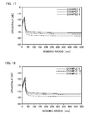
FIG. 16 is a diagram of the relationship between crosstalk and the bending radii of multi-core fibers according to a third example to a fifth example; -
FIG. 17 is a diagram of the relationship between crosstalk and the bending radii of multi-core fibers according to a sixth example to an eighth example; -
FIG. 18 is a diagram of the relationship between crosstalk and the bending radii of multi-core fibers according to a ninth example to an eleventh example; -
FIG. 19 is a diagram of the distribution of the effective refractive index Δneff of a core at a wavelength of 1,550 nm according to a twelfth example and a thirteenth example similar toFIG. 8 ; -
FIG. 20 is a diagram of the relationship between crosstalk and the bending radius of a multi-core fiber according to the twelfth example; and -
FIG. 21 is a diagram of the relationship between crosstalk and the bending radius of a multi-core fiber according to the thirteenth example. - A preferred embodiment of a multi-core fiber according to the present invention will be described in detail below referring to the drawings. In addition, for ease of understanding, a scale disclosed in each drawing and a scale disclosed below are different in some cases.
-
FIGS. 1A and 1B are diagrams of a multi-core fiber according to an embodiment of the present invention. More specifically,FIG. 1A is a diagram of a structure on a cross section perpendicular to the longitudinal direction of the multi-core fiber, andFIG. 1B is a schematic diagram of effective refractive indices along a line B-B of the multi-core fiber 1 inFIG. 1A . It is noted thatFIG. 1B schematically depicts the effective refractive indices in the case where the multi-core fiber is disposed linearly. - As depicted in
FIG. 1A , the multi-core fiber 1 according to the embodiment includes a plurality of two types ofcores cores cores cores protective layer 31 that covers the outer circumferential surface of the clad 20, and an outerprotective layer 32 that covers the outer circumferential surface of the innerprotective layer 31. - As depicted by a solid line in
FIG. 1B , the refractive indices of thecores cores core 11 and the core 12 are alternately disposed, a core pitch D between the core 11 and the core 12 adjacent to each other is set constant, and thecores cores cores cores core 11 is disposed is matched with the axis of the clad 20. The fact that thecores cores cores cores 11 and thecores 12 is an even number. - Moreover, the core pitch D of the multi-core fiber 1 ranges from 30 µm to 50 µm. The core pitch D is 30 µm or more, so that the crosstalk between cores adjacent to each other can be suppressed. Furthermore, the core pitch D is 50 µm or less, and the diameter of the multi-core fiber 1 can be kept smaller. Thus, even in the case where the multi-core fiber 1 is disposed in the state in which the multi-core fiber 1 is bent, the possibility of breakage can be reduced.
- Furthermore, a mode field diameter difference ΔMFD between the
cores cores core 11 and an effective refractive index neff12 of the core 12 adjacent to each other, and the difference is indicated by broken lines inFIG. 1B . The effective refractive index difference Δneff between thecores 
- In order to obtain the effective refractive index difference Δneff satisfying Expression (1) and the mode field diameter difference ΔMFD, although not particularly specified, such a configuration may be possible in the
core 11, for example, in which a radius d1 is 4.5 µm and a refractive index difference Δ11 with respect to the clad 20 is 0.40%, and in thecore 12, a radius d2 is 4.0 µm and a refractive index difference Δ12 with respect to the clad 20 is 0.35%. Moreover, the diameter of the clad 20 is 160 µm, for example. It is noted that in the multi-core fiber 1 according to the embodiment, as depicted inFIG. 1A , the number of the cores is six in total, and thecores - Next, the relationship between the effective refractive index difference between the cores adjacent to each other and the bending radius of the multi-core fiber at which the crosstalk between the cores adjacent to each other is at a peak will be described.
- A bending radius Rpk of the multi-core fiber at which the crosstalk between the cores adjacent to each other is at a peak is given by Expression (2) below. However, in Expression (2) below, neff11 is the effective refractive index of the core 11, which is one of the
cores cores cores 
-
FIG. 2 is a diagram of the distribution of the effective refractive index difference between the cores for individual effective refractive index differences in the case where a core pitch in the multi-core fiber and a bending radius at which crosstalk is at a peak are determined.FIG. 2 can be depicted using Expression (2) above. It is noted that inFIG. 2 , the effective refractive index of the core 11 neff11 is 1.45. However, the effective refractive index of the core 11 neff11 is a considerably larger value than the value of the effective refractive index difference Δneff between thecores FIG. 2 is not changed so much. - However, when the optical fiber is bent at a small bending radius as described above, the probability of fatigue failure is increased and the attenuation of light propagating through the core due to the bend becomes large, for example. Because of the reasons, the minimum bending radius of the optical fiber is generally 100 mm. Thus, it is considered that crosstalk can be sufficiently suppressed under a general use environment of an optical fiber when the bending radius Rpk of an optical fiber at which crosstalk is at a peak is smaller than the minimum bending radius. Thus, in a range in which the core pitch ranges from 30 µm to 50 µm, the effective refractive index difference Δneff between the
cores margin 30% or more of the margin of a minimum bending radius of 100 mm for an optical fiber. -
FIG. 3 is a diagram thatFIG. 2 is rewritten on the dependence of the effective refractive index difference Δneff between thecores FIG. 3 , in the case where the bending radius Rpk is 100 mm and in the case where the bending radius Rpk is 70 mm, the dependence of the effective refractive index difference Δneff between thecores - As depicted in
FIG. 3 , in the case where the bending radius Rpk is 100 mm, the relationship between the effective refractive index difference Δneff and the core pitch D is expressed by Expression (3).
- In order to achieve the bending radius Rpk smaller than 100 mm, the effective refractive index difference Δneff may be greater than a value expressed by Expression (3). Therefore, Expression (4), which is a part of Expression (1), can be obtained by removing the second term ten digits smaller in units.

- It is shown that the peak of crosstalk becomes smaller than 100 mm when Expression (4) is satisfied.
- Moreover, in the case where the bending radius Rpk is 70 mm, Expression (5) is satisfied.

- Thus, more preferably, in the multi-core fiber 1 depicted in
FIGS. 1A and 1B , the effective refractive index difference Δneff between thecores 
- In this case, the peak of crosstalk becomes 70 mm or less.
- Furthermore, it is shown from
FIG. 2 that the effective refractive index difference Δneff at which the bending radius Rpk is 70 mm or less is generally 0.001 or more regardless of the core pitch. Therefore, in the multi-core fiber 1 depicted inFIGS. 1A and 1B , the effective refractive index difference Δneff between thecores cores - Next, as described above, cores that can be disposed in the multi-core fiber will be described in the case where the effective refractive index difference Δneff between the
cores -
FIG. 4 is a diagram of the distribution of the effective refractive index of a core for individual effective refractive indices at a wavelength of 1,550 nm in the case where the radius of the core and the refractive index difference between the core and a clad are determined in a typical optical fiber. InFIG. 4 , the horizontal axis expresses the radius of the core, and the vertical axis expresses the refractive index difference between the core and the clad. Moreover, a hatched region is a region in which the bending loss is 0.5 dB or more in the case where light at a wavelength of 1,625 nm is wound at 100 turns at a radius of 30 mm. This region is a region that is not allowed for use in optical fibers in a waveband of 1.5 µm because bending losses are large. Furthermore, λc indicated by a dotted line expresses a cutoff wavelength of 1,530 nm. In the optical fiber in a waveband of 1.5 µm, the region on the right side of λc indicated by a dotted line is a region not allowed for use. - In
FIG. 4 , solid lines indicate the distributions of effective refractive indices. Here, attention is focused on two effective refractive indices 1.4530 and 1.4520 between which the effective refractive index difference Δneff is 0.001, for example. As apparent fromFIG. 4 , a solid line at which the effective refractive index is 1.4530 and a solid line at which the effective refractive index is 1.4520 are distributed in a wider range than the region in which the multi-core fiber can be used (the region not included in the hatched region and on the left side of λc indicated by a dotted line). Thus, two types of cores between which the effective refractive index difference Δneff is 0.001 can be designed in such a way that the cores are located in the region in which the optical fiber can be used. Here, when the core pitch D ranges from 30 µm to 50 µm, which are the maximum values of a practical core pitch, from Expression (3) above, the effective refractive index difference Δneff ranges 0.000435 to 0.000725, which are smaller than 0.001. It is noted that the second term of Expression (3) is ignored because the value is considerably small. Thus, the effective refractive index difference Δneff that the second term of Expression (3) above is ignored is distributed in a wide range in which the multi-core fiber can be used. In other words, in this case, the cores can coexist in a single clad. - On the other hand, from
FIG. 4 , in the case where attention is focused on two effective refractive indices between which the effective refractive index difference Δneff exceeds 0.002, when the effective refractive index is determined for one of the cores in such a way that the core is located in the usable region, it is difficult to determine the effective refractive index for the other core in such a way that the core is located in the usable region. In other words, in order to dispose two cores in a single clad in the usable state, the effective refractive index difference Δneff may be 0.002 or less. - This means that the effective refractive index difference Δneff between the core 11 and the
core 12 of the multi-core fiber 1 satisfies Expression (1) above. -
FIG. 5 is a diagram similar toFIG. 4 in the case of a wavelength of 1,450 nm. Also inFIG. 5 , as similar to the description usingFIG. 4 , it is shown that two cores can be disposed in a single clad when the effective refractive index difference Δneff satisfies Expression (1) above. Moreover,FIG. 6 is a diagram similar toFIG. 4 in the case of a wavelength of 1,625 nm. As also apparent fromFIG. 6 , as similar toFIG. 4 , it is shown that two cores can be disposed in a single clad when the effective refractive index difference Δneff satisfies Expression (1) above. In other words, as apparent from the description usingFIGS. 4 to 6 , it is shown that in order to dispose two cores in a single clad regardless of the wavelength, the effective refractive index difference Δneff satisfies Expression (1) above. - Next, the splicing loss caused by the difference in the mode field diameter of light propagating through the cores will be described.
- Suppose that there are two optical fibers whose mode field diameter of light propagating through the core is different from each other, and the mode field diameters of light are MFD1 and MFD2. An optical attenuation a produced in the case where the optical fibers are connected to each other can be expressed by Expression (7) below.

- From Expression (7) above, for example, in the case where the mode field diameters of light propagating through the cores of two optical fibers are 9 µm and 8.4 µm, the splicing loss a is 0.04 dB. At such a splicing loss, two optical fibers can be connected to each other with no practical troubles. Moreover, in the case where the mode field diameter difference between the optical fibers is 1 µm, the splicing loss a becomes 0.06 dB. Also in this case, two optical fibers can be connected to each other with no practical troubles. As described above, since the mode field diameter difference between the core 11 and the
core 12 of the multi-core fiber 1 is 1 µm or less, in the case where a plurality of the multi-core fibers 1 is connected, splicing losses with no practical troubles are achieved even though thecore 11 and the core 12 are connected to each other. Moreover, the fact that thecore 11 and the core 12 may have different mode field diameters means that the diameter of the core can be adjusted in a range in which the difference in the mode field diameter of light propagating through the cores is 1 µm or less in the multi-core fiber 1. Thus, even in the case where the refractive index difference between the cores and the clad is varied, it is shown that the diameter of the core is adjusted to achieve the effective refractive index at an appropriate value. - It is noted that single mode fibers generally widely used are defined in ITU-T G.652 Recommendation (version in November 2009), and the tolerance of the mode field diameter is specified in ±0.6 µm. Moreover, long distance transmission fibers such as a submarine line are defined in ITU-T G.654 Recommendation (in December 2006), and the tolerance of the mode field diameter is specified in ±0.7 µm. The tolerances are defined from the viewpoint of splicing losses including axial displacement. Thus, when the mode field diameter difference is 1 µm or less as described above, splicing losses low enough can be secured in compliance with the international recommendations.
- Furthermore,
FIGS. 4 to 6 are diagrams of the distribution of the effective area Aeff of the core for individual effective areas expressed by broken lines in the case where the radius of the core and the refractive index difference between the core and the clad are determined. The relationship between the mode field diameter MFD of light propagating through the optical fiber and the effective area Aeff at this time is expressed by Expression (8) below.
- In the case where the mode field diameter is 10 µm, Aeff takes a value reneging from 75 µm2 to 77 µm2. Suppose that a variation in the mode field diameter MFD is Δ in the case where the mode field diameter MFD is changed from MFD1 to MFD2, a variation ΔAeff in the effective area Aeff of the core is given by Expression (9) below. It is noted that Aeff1 expresses the effective area in the case where the mode field diameter is MFD1, and Aeff2 expresses the effective area in the case where the mode field diameter is MFD2.

- Therefore, when the mode field diameter is changed by 1 µm from 10 µm to 11 µm, the effective area of the core is changed from 15.8 µm2 to 16.2 µm2. Thus, for example, in
FIG. 4 , cores between which the mode field diameter difference is smaller than 1 µm are designed in such a way that the effective areas Aeff of the cores are 70 µm2 and 80 µm2 and the effective refractive index difference Δneff satisfies Expression (1) above. In such a design, a reduction in crosstalk and a reduction in splicing losses can be combined. Two cores between which the mode field diameter is different by 1 µm as described above are both located in the region in which the optical fiber can be used, so that these two cores can be disposed simultaneously in a single clad. Thus, as described above, since the mode field diameter difference between the core 11 and thecore 12 of the multi-core fiber 1 is 1 µm or less, so that thecore 11 and the core 12 are in the usable state. - As described above, in accordance with the multi-core fiber 1 according to the embodiment, the difference in the mode field diameter of light propagating through the cores is 1 µm or less, so that splicing losses can be made smaller regardless of the combination of cores in the case where a plurality of the multi-core fibers is connected.
- Moreover, in the multi-core fiber 1, an even number of six or more of cores are annularly disposed as described above, and a specific core is not disposed adjacently to three or more of cores. Thus, different types of cores can be always alternately disposed using two types of the
cores cores - Next, a second embodiment of the present invention will be described in detail with reference to
FIGS. 7A and 7B . It is noted that components the same as or equivalent to the components of the first embodiment are designated the same reference numerals and signs, and the overlapping description is omitted unless otherwise specified. -
FIGS. 7A and 7B are diagrams of a multi-core fiber according to the second embodiment of the present invention. More specifically,FIG. 7A is a diagram of a structure on a cross section perpendicular to the length direction of amulti-core fiber 2 according to the embodiment, andFIG. 7B is a schematic diagram of refractive index profiles and effective refractive indices along line B-B inFIG. 7A . Thus, the relationship between the refractive index and the effective refractive index does not always fall as inFIG. 7B . - As depicted in
FIG. 7A , themulti-core fiber 2 according to the embodiment is different from the multi-core fiber 1 according to the first embodiment in that themulti-core fiber 2 includes a first clad 13 that surrounds the outer circumferential surfaces ofcores core 11, the first clad 13 surrounding thecore 11, and the second clad 14 surrounding the first clad 13 are referred to as afirst core element 11a, and thecore 12, the first clad 13 surrounding thecore 12, and the second clad 14 surrounding the first clad 13 are referred to as asecond core element 12a. In the embodiment, the outer diameters of the first clads 13 are equal to each other, and the outer diameters of the second clads 14 are equal to each other. Thus, the thicknesses of the first clads 13 are equal to each other, and the thicknesses of the second clads 14 are equal to each other. Moreover, although not limited particularly, for example, the outer diameter of the first clad 13 is 19 µm, and the outer diameter of the second clad 14 is 27 µm. - Furthermore, suppose that the refractive index of the
core 11 is n1-1 and the refractive index of thecore 12 is n1-2. As depicted inFIG. 7B , a refractive index n2 of the first clad 13 is made lower than the refractive index n1-1 of thecore 11 and the refractive index n1-2 of the core 12, and a refractive index n3 of the second clad 14 is further made lower than the refractive index n2 of the first clad 13. In addition, a refractive index n4 of the clad 20 is made lower than the refractive index n1-1 of thecore 11 and the refractive index n1-2 of the core 12, and made higher than the refractive index n3 of the second clad 14. In other words, the refractive indices n1-1 to n4 satisfy all of expressions.


- Thus, in the case where the
core elements core elements - It is noted that in
FIG. 7B , the refractive indices of an innerprotective layer 31 and an outerprotective layer 32 are omitted. - As described above, the refractive index n3 of the second clad 14 is made smaller than the refractive index n2 of the first clad 13 and the refractive index n4 of the clad 20, so that the optical confinement effect of the
cores cores core elements cores - As similar to the multi-core fiber 1 according to the first embodiment, a mode field diameter difference ΔMFD between the core 11 of the
core element 11a and thecore 12 of thecore element 12a adjacent to each other is 1 µm or less, and an effective refractive index difference Δneff between the core 11 of thecore element 11a and thecore 12 of thecore element 12a adjacent to each other satisfies Expression (1) above. - It is noted that the refractive index difference between the first clad 13 and the clad 20 is often nearly zero. However, the refractive index difference is appropriately set to positive and negative values in order to adjust the wavelength dispersion characteristics. Thus, in
FIG. 7B , the refractive index n2 of the first clad 13 is set similar to the refractive index n4 of the clad 20. However, the refractive index n2 of the first clad 13 may be set between the refractive index n4 of the clad 20 and the refractive index n1-1 of thecore 11 and the refractive index n1-2 of the core 12, or may be set between the refractive index n4 of the clad 20 and the refractive index n3 of the second clad 14. -
FIG. 8 is a diagram of the distribution of the effective refractive index of a core shown by a method similar to the method inFIG. 4 in the case where the radius of the core and the refractive index difference between the core and a clad are determined at a wavelength of 1,550 nm, in an optical fiber including a core element in a trench structure in which the ratio of the thickness of a second clad to the radius of the core is 1.0 and the ratio of the radius of the circumference of a first clad to the radius of the core is 2.0. Also inFIG. 8 , a hatched region is a region in which the bending loss is 0.5 dB or more in the case where light at a wavelength of 1,625 nm is wound at 100 turns at a radius of 30 mm and is the region not usable in the optical fiber in a waveband of 1.5 µm, and the cutoff wavelength is a wavelength of 1,530 nm or more in the region at the upper right of a dotted line indicated as λc. - In
FIG. 8 , as similar to the description usingFIG. 4 , attention is focused on two effective refractive indices 1.4530 and 1.4520 between which the effective refractive index difference Δneff is 0.001, for example. A solid line at which the effective refractive index is 1.4530 and a solid line at which the effective refractive index is 1.4520 are distributed in a wider range than the region in which the multi-core fiber can be used (the region not included in the hatched region and on the left side of λc indicated by a dotted line). Thus, two types of cores between which the mode field diameter difference is smaller than 1 µm and between which the effective refractive index difference Δneff is 0.001 can be designed in such a way that the cores are located in the region in which the optical fiber can be used. Moreover, as described in the first embodiment, when the core pitch D ranges from 30 µm to 50 µm from Expression (3), the effective refractive index difference Δneff is smaller than 0.001. Thus, the effective refractive index difference Δneff given by Expression (3) is distributed in a wide range in which the multi-core fiber can be used. In other words, even in the multi-core fiber having the core elements in the trench structure, in this case, the core elements can coexist in a single clad. - On the other hand, also in
FIG. 8 , as similar toFIG. 4 , attention is focused on two effective refractive indices between which the mode field diameter difference is smaller than 1 µm and between which the effective refractive index difference Δneff exceeds 0.002. When the effective refractive index is determined for one of the cores in such a way that the core is located in the usable region, it is difficult to determine the effective refractive index for the other core in such a way that the core is located in the usable region. Thus, even in the multi-core fiber having the core elements in the trench structure, in order to dispose two cores in a single clad in the usable state, the effective refractive index difference Δneff may be 0.002 or less. - This means that the effective refractive index difference Δneff between the core 11 and the
core 12 of themulti-core fiber 2 satisfies Expression (1) above, as described above. -
FIG. 9 is a diagram similar toFIG. 8 in the case of an optical fiber in which the ratio of the thickness of a second clad to the radius of the core is 1.1 and the ratio of the radius of the circumference of a first clad to the radius of the core is 1.9. Also inFIG. 9 , as similar to the description usingFIG. 8 , it is shown that two cores can be disposed in a single clad when the effective refractive index difference Δneff satisfies Expression (1) above. Moreover,FIG. 10 is a diagram similar toFIG. 8 in the case of an optical fiber in which the ratio of the thickness of a second clad to the radius of the core is 1.2 and the ratio of the radius of the circumference of a first clad to the radius of the core is 1.8.FIG. 11 is a diagram similar toFIG. 8 in the case of an optical fiber in which the ratio of the thickness of a second clad to the radius of the core is 1.3 and the ratio of the radius of the circumference of a first clad to the radius of the core is 1.7. Also inFIGS. 10 and 11 , as similar toFIG. 4 , it is shown that two cores can be disposed in a single clad when the effective refractive index difference Δneff satisfies Expression (1) above. In other words, as apparent from the description usingFIGS. 8 to 11 , it is shown that in order to dispose two cores in a single clad regardless of the ratio of the thickness of the second clad to the radius of the core and the ratio of the radius of the circumference of the first clad to the radius of the core, the effective refractive index difference Δneff satisfies Expression (1) above. - It is noted that in the embodiment, the refractive indices n2 of the first clads 13 are equal to each other in the
core elements core elements core element 11a and the refractive index n2 of the first clad 13 in thecore element 12a may have different refractive indices from each other depending on the effective refractive index difference Δneff between the core 11 and thecore 12. Similarly, the refractive index n3 of the second clad 14 in thecore element 11a and the refractive index n3 of the second clad 14 in thecore element 12a may have different refractive indices from each other depending on the effective refractive index difference Δneff between the core 11 and thecore 12. - As described above, in accordance with the
multi-core fiber 2 according to the embodiment, in thecore elements cores core 11 and the refractive index n1-2 of the core 12, and the first clad 13 is surrounded by the second clad 14 having the refractive index n3 smaller than the refractive index n2 of the first clad 13. Thus, light propagating through thecores cores core 11 and the refractive index n1-2 of the core 12, light is attracted to thecores cores core elements multi-core fiber 2, the crosstalk between thecores - It is noted that in the description above, the outer diameters of the first clads 13 are equal to each other, and the outer diameters of the second clads 14 are equal to each other. However, for example, the outer diameter of the first clad 13 in the
core element 11a and the outer diameter of the first clad 13 in thecore element 12a may be different from each other depending on the effective refractive index difference Δneff between the core 11 and thecore 12, and the outer diameter of the second clad 13 in thecore element 11a and the outer diameter of the second clad 14 in thecore element 12a may be different from each other depending on the effective refractive index difference Δneff between the core 11 and thecore 12. - Although the present invention has been described above by reference to a certain embodiment as an example, the present invention is not limited thereto.
- For example, in the first and the second embodiments, the number of the cores is six. However, the number of the cores is an even number of six or more, and the number is not limited specifically as long as the cores can be accommodated in the clad 20.
FIG. 12 is a diagram of an example of this multi-core fiber, and is a diagram of an exemplary modification of the multi-core fiber according to the second embodiment. It is noted that in describingFIG. 12 , components the same as or equivalent to the components of the second embodiment are designated the same reference numerals and signs, and the overlapping description is omitted unless otherwise specified. In amulti-core fiber 3 depicted inFIG. 12 , the numbers of thecore elements cores cores cores - Moreover, in the case where the number of the
cores cores FIG. 13 is a diagram of an example of this multi-core fiber, and is a diagram of another exemplary modification of the multi-core fiber according to the second embodiment. It is noted that in describingFIG. 13 , components the same as or equivalent to the components of the second embodiment are designated the same reference numerals and signs, and the overlapping description is omitted unless otherwise specified. In amulti-core fiber 4 depicted inFIG. 13 , as similar to the multi-core fiber depicted inFIG. 12 , the numbers of thecore elements cores cores cores 11 is n, the cores may be disposed in a regular hexagon as a whole in which the cores are disposed at vertices and on sides and the core pitches are equal as in the exemplary modification. In this case, the number of the cores is a multiple of six, 12 or more. As described above, even though thecores cores - Hereinafter, although the present invention will be more concretely explained with examples and comparative examples, the present invention is not limited thereto.
- A multi-core fiber made of pure silica glass was prepared in which six cores formed of two types of cores were disposed in a clad having a diameter of 160 µm in a regular hexagon as a whole at regular spacings. Two types of the cores were alternately disposed, and the core pitch between the cores adjacent to each other was 40 µm. In one of the two types of the cores, the radius was 4.5 µm, the refractive index difference with respect to the clad was 0.40%, and the effective refractive index was 1.453. Moreover, in the other of the two types of the cores, the radius was 4.0 µm, the refractive index difference with respect to the clad was 0.35%, and the effective refractive index was 1.452. Thus, the effective refractive index difference between the cores adjacent to each other is 0.001.
- In the case where light at a wavelength of 1,550 nm was propagated through this multi-core fiber, in one of the two types of the cores, the cutoff wavelength was a wavelength of 1,382 nm, the effective area was 76.8 µm2, the mode field diameter was 10.1 µm, a bending loss at a bending radius of 10 mm was 1.6 dB/m, and the wavelength dispersion was 18.6. Moreover, in the other of the two types of the cores, the cutoff wavelength was a wavelength of 1,147 nm, the effective area was 78.3 µm2, the mode field diameter was 10.6 µm, a bending loss at a bending radius of 10 mm was 93 dB, and the wavelength dispersion was 16.1 ps/nm/km. Thus, the mode field diameter difference between the two types of the cores was 0.5 µm. Even in the case where different cores were fusion-spliced to each other, a significantly excellent value was obtained for the splicing loss as 0.12 dB.
- Next, signal light at a wavelength of 1,550 nm was propagated through this multi-core fiber for 100 km, and the relationship between the bending radius and the crosstalk was examined. The result is shown in
FIG. 14 . - From
FIG. 14 , a bending radius at which crosstalk was at a peak was about 50 mm. Moreover, at a bending radius of 100 mm, which is the minimum bending radius at which a typical optical fiber can be used, the crosstalk was rarely degraded. - In one of two types of cores, the radius was 4.8 µm, the refractive index difference with respect to the clad was 0.41%, and the effective refractive index was 1.4534. Moreover, in the other of the two types of the cores, the radius was 4.3 µm, the refractive index difference with respect to the clad was 0.36%, and the effective refractive index was 1.4524. Thus, the effective refractive index difference between the cores adjacent to each other is 0.001. The conditions other than these were set similar to the conditions in the first embodiment.
- In the case where light at a wavelength of 1,550 nm was propagated through this multi-core fiber, in one of the two types of the cores, the cutoff wavelength was a wavelength of 1,489 nm, the effective area was 80.2 µm2, the mode field diameter was 10.2 µm, a bending loss at a bending radius of 10 mm was 0.37 dB/m, and the wavelength dispersion was 19.5. Moreover, in the other of the two types of the cores, the cutoff wavelength was a wavelength of 1,247 nm, the effective area was 79.5 µm2, the mode field diameter was 10.5 µm, a bending loss at a bending radius of 10 mm was 25 dB, and the wavelength dispersion was 17.5 ps/nm/km. Thus, the mode field diameter difference between the two types of the cores was 0.3 µm.
- The average fusion splicing loss of this multi-core fiber was significantly small as 0.09 dB. As described above, it was shown that the splicing loss was small in the case where a plurality of the multi-core fibers was connected because the multi-core fiber according to the example had a small mode field diameter difference between the cores.
- Next, signal light at a wavelength of 1,550 nm was propagated through this multi-core fiber for 100 km, and the relationship between the bending radius and the crosstalk was examined. The result is shown in
FIG. 15 . - From
FIG. 15 , a bending radius at which crosstalk was at a peak was about 50 mm. Crosstalk was rarely degraded at a bending radius of 100 mm, which is the minimum bending radius at which the optical fiber can be generally used. - Parameters shown in Table 1 below were used to prepare a multi-core fiber in which 12 of two types of cores elements were disposed in a regular dodecagon as a whole as depicted in
FIG. 12 and a multi-core fiber in which 12 of two types of cores elements were disposed in a regular hexagon as a whole as depicted inFIG. 13 . However, the core pitch was set to 31 µm. The outer diameter of the clad of the multi-core fiber in which the cores were disposed in a regular dodecagon as a whole ranged from 188 µm to 196 µm, and the outer diameter of the clad of the multi-core fiber in which the cores were disposed in a regular hexagon as a whole ranged from 192 µm to 200 µm. Moreover, the effective areas Aeff of the cores at a wavelength of 1,550 nm were 90 µm2, and the cable cutoff wavelength was a wavelength of 1,530 nm. It is noted that in Table 1, w expresses the thickness of the second clad, r1 expresses the radii of the cores, and r2 expresses the radius of the circumference of the first clad. Thus, w/r1 expresses the ratio of the thickness of the second clad to the radius of the core, and r2/r1 expresses the ratio of the radius of the circumference of the first clad to the radius of the core. Furthermore, Δ1 expresses the refractive index difference between the cores and the clad. In addition, since differences in characteristics were not observed between the multi-core fiber in which the cores were disposed in a regular dodecagon as a whole and the multi-core fiber in which the cores were disposed in a regular hexagon as a whole specifically, the multi-core fiber in which the cores were disposed in a regular dodecagon as a whole and the multi-core fiber in which the cores were disposed in a regular hexagon as a whole, which were prepared according to the parameters below, are categorized in one embodiment.Table 1 w/r1 r2/r1 core 1 core 2Δneff r1 [µm] Δ1 [%] r1 [µm] Δ1 [%] Third Example 1.0 2.0 5.00 0.330 4.59 0.268 0.00099 Fourth Example 1.1 1.9 5.00 0.322 4.59 0.255 0.00105 Fifth Example 1.2 1.8 5.00 0.308 4.62 0.244 0.00100 - Next, signal light at a wavelength of 1,550 nm was propagated through these multi-core fibers for 100 km, and the relationship between the bending radius and the crosstalk was examined. The result is shown in
FIG. 16 . - From
FIG. 16 , a bending radius at which crosstalk was at a peak was about 20 mm. Moreover, at a bending radius of 100 mm, which is the minimum bending radius at which a typical optical fiber can be used, the crosstalk was rarely degraded. - Next, multi-core fibers similar to the multi-core fibers according to the third example to the fifth example were prepared as core pitches were 32 µm. The parameters of the multi-core fiber according to a sixth example were similarly set to the parameters of the third example, the parameters of the multi-core fiber according to a seventh example were similarly set to the parameters of the fourth embodiment, and the parameters of the multi-core fiber according to an eight example were similarly set to the parameters of the fifth example.
- Next, signal light at a wavelength of 1,550 nm was propagated through these multi-core fibers for 100 km, and the relationship between the bending radius and the crosstalk was examined. The result is shown in
FIG. 17 . - From
FIG. 17 , a bending radius at which crosstalk was at a peak was about 20 mm. Moreover, at a bending radius of 100 mm, which is the minimum bending radius at which a typical optical fiber can be used, the crosstalk was rarely degraded. - Next, multi-core fibers similar to the multi-core fibers in the third example to the fifth example were prepared as core pitches were 33 µm. The parameters of the multi-core fiber according to a ninth example were similarly set to the parameters of the third example, the parameters of the multi-core fiber according to a tenth example were similarly set to the parameters of the fourth embodiment, and the parameters of the multi-core fiber according to an eleventh example were similarly set to the parameters of the fifth example.
- Next, signal light at a wavelength of 1,550 nm was propagated through these multi-core fibers for 100 km, and the relationship between the bending radius and the crosstalk was examined. The result is shown in
FIG. 18 . - From
FIG. 18 , a bending radius at which crosstalk was at a peak was about 25 mm. Moreover, at a bending radius of 100 mm, which is the minimum bending radius at which a typical optical fiber can be used, the crosstalk was rarely degraded. - An analysis was conducted on the structure of a multi-core fiber in which two types of ten core elements in a trench structure in total were alternately disposed, in which the core pitches were equal to each other and the cores were disposed in a rectangular decagon as in the
multi-core fiber 2 according to the second embodiment. In a multi-core fiber according to a twelfth example, the effective refractive index Aeff was 110 µm2, and in a multi-core fiber according to a thirteenth example, the effective refractive index Aeff was 100 µm2. Moreover, in the multi-core fibers, a refractive index difference Δ2 between the first clad and the clad was 0.0%, and a refractive index difference Δ3 between the second clad and the clad was - 0.7%. Furthermore, the other parameters were set as parameters in Table 2 below.Table 2 w/r1 r2/r1 core 1 core 2Δneff r1 [µm] Δ1 [%] r1 [µm] Δ1 [%] Twelfth Example 1.0 2.0 5.56 0.269 5.03 0.213 0.0009 Thirteenth Example 1.0 2.0 5.30 0.300 4.82 0.238 0.001 - The distribution of the effective refractive index Δneff of the core at a wavelength of 1,550 nm was calculated. The calculated reset is shown in
FIG. 19 . - Δneff of the cores according to the twelfth example and the thirteenth example was values satisfying Expression (1). As depicted in
FIG. 19 , it was enabled to be confirmed that the cores according to the twelfth example and the thirteenth example were located in a usable region. - Next, the parameters according to the twelfth example were used to prepare a multi-core fiber in which the core pitch was 34 µm and the pitch from the outer circumferential surface of the clad to the core (the thickness of the outer clad) was 40 µm, and a multi-core fiber in which the core pitch was 37 µm and the thickness of the outer clad was 40 µm. The outer diameter of the clad was 190 µm for the multi-core fiber in which the core pitch was 34 µm, and the outer diameter of the clad was 200 µm for the multi-core fiber in which the core pitch was 37 µm.
- Next, signal light at a wavelength of 1,550 nm was propagated through the multi-core fibers for 100 km, and the relationship between the bending radius and the crosstalk was examined. The result is shown in
FIG. 20 . - From
FIG. 20 , a bending radius at which crosstalk was at a peak was about 60 mm to 70 mm. Moreover, at a bending radius of 100 mm, which is the minimum bending radius at which a typical optical fiber can be used, crosstalk was rarely degraded. The multi-core fiber in which the core pitch was 34 µm achieved a low crosstalk as about -40 dB at the usable bending radius. The multi-core fiber in which the core pitch was 37 µm achieved a much lower crosstalk as about -50 dB at the usable bending radius. - Next, the parameters according to the thirteenth example were used to prepare a multi-core fiber in which the core pitch was 33 µm and the thickness of the outer clad was 37 µm and a multi-core fiber in which the core pitch was 38 µm and the thickness of the outer clad was 37 µm. The outer diameter of the clad was 181 µm for the multi-core fiber in which the core pitch was 33 µm, and the outer diameter of the clad was 197 µm for the multi-core fiber in which the core pitch was 38 µm.
- Next, signal light at a wavelength of 1,550 nm was propagated through the multi-core fibers for 100 km, and the relationship between the bending radius and the crosstalk was examined. The result is shown in
FIG. 21 . - From
FIG. 21 , a bending radius at which crosstalk was at a peak was about 50 mm to 60 mm. Moreover, at a bending radius of 100 mm, which is the minimum bending radius at which a typical optical fiber can be used, crosstalk was rarely degraded. The multi-core fiber in which the core pitch was 33 µm achieved a low crosstalk as about -40 dB at the usable bending radius. The multi-core fiber in which the core pitch was 38 µm achieved a much lower crosstalk as about -50 dB at the usable bending radius. - As described above, from the results of the examples, it was confirmed that the effective refractive index difference between the cores adjacent to each other satisfies Expression (1) and the bending radius of the optical fiber at which crosstalk is at a peak is a bending radius smaller than a bending radius of 100 mm, which is the minimum bending radius at which a typical optical fiber can be used. Moreover, it was confirmed that the difference in the mode field diameter of light propagating through the cores is as small as 1 µm or less, and splicing losses can be suppressed. Thus, according to the present invention, it can be considered that the crosstalk between cores adjacent to each other can be suppressed even in the case where the multi-core fiber 1 is nonlinearly disposed while suppressing splicing losses.
- As described above, according to the present invention, there is provided a multi-core fiber that can suppress the crosstalk between cores adjacent to each other even in the case where the multi-core fiber is nonlinearly disposed while suppressing splicing losses, and the multi-core fiber can be excellently used for communication cables, for example.
-
- 1 to 4
- Multi-core fiber
- 11, 12
- Core
- 11a, 12a
- Core element
- 13
- First clad
- 14
- Second clad
- 20
- Clad
- 31
- Inner protective layer
- 32
- Outer protective layer
Claims (6)
- A multi-core fiber comprising:an even number of six or more of cores; anda clad surrounding outer circumferential surfaces of the cores, wherein:the even number of cores are formed of two types of cores between which an effective refractive index difference in a fundamental mode is different;in the cores, the two types of cores are alternately disposed at regular spacings, and the cores are annularly disposed at an interior angle formed of lines connecting centers of the cores adjacent to each other, the interior angle being greater than an angle of 90°;a difference in a mode field diameter of light propagating through the cores is 1 µm or less; andan expression is satisfied:wherein an inter-center pitch between the cores adjacent to each other is D µm and an effective refractive index difference between the cores adjacent to each other is Δneff.

- The multi-core fiber according to claim 1, wherein the inter-center pitch and the effective refractive index difference further satisfy an expression:

- The multi-core fiber according to claim 2, wherein the effective refractive index difference further satisfies an expression:

- The multi-core fiber according to claims any one of 1 to 3, wherein when the number of cores is n, the cores are disposed in an n-sided regular polygon.
- The multi-core fiber according to claims any one of 1 to 3, wherein the cores are disposed in a regular hexagon.
- The multi-core fiber according to claims any one of 1 to 5, further comprising:a first clad surrounding outer circumferential surfaces of the cores; anda second clad surrounding an outer circumferential surface of the first clad, an outer circumferential surface of the second clad being surrounded by the clad,wherein all of expressions are satisfied:wherein a refractive index of one of the two types of cores is n1-1, a refractive index of the other of the two types of cores is n1-2, a refractive index of the first clad is n2, a refractive index of the second clad is n3, and a refractive index of the clad is n4.


Applications Claiming Priority (3)
| Application Number | Priority Date | Filing Date | Title |
|---|---|---|---|
| JP2012009458 | 2012-01-19 | ||
| JP2012134673A JP5916525B2 (en) | 2012-01-19 | 2012-06-14 | Multi-core fiber |
| PCT/JP2012/082284 WO2013108523A1 (en) | 2012-01-19 | 2012-12-13 | Multi-core fiber |
Publications (3)
| Publication Number | Publication Date |
|---|---|
| EP2806297A1 true EP2806297A1 (en) | 2014-11-26 |
| EP2806297A4 EP2806297A4 (en) | 2015-06-17 |
| EP2806297B1 EP2806297B1 (en) | 2019-09-25 |
Family
ID=48798960
Family Applications (1)
| Application Number | Title | Priority Date | Filing Date |
|---|---|---|---|
| EP12866305.1A Active EP2806297B1 (en) | 2012-01-19 | 2012-12-13 | Multi-core fiber |
Country Status (4)
| Country | Link |
|---|---|
| US (1) | US9081129B2 (en) |
| EP (1) | EP2806297B1 (en) |
| JP (1) | JP5916525B2 (en) |
| WO (1) | WO2013108523A1 (en) |
Cited By (6)
| Publication number | Priority date | Publication date | Assignee | Title |
|---|---|---|---|---|
| US9291768B2 (en) | 2013-11-25 | 2016-03-22 | Fujikura Ltd. | Multicore fiber |
| EP3029498A1 (en) * | 2014-03-07 | 2016-06-08 | Fujikura Ltd. | Multi-core fiber |
| WO2018150699A1 (en) | 2017-02-15 | 2018-08-23 | 株式会社フジクラ | Optical fiber sensor |
| CN112099130A (en) * | 2020-09-25 | 2020-12-18 | 东北大学 | Slope-type refractive index distribution multi-core optical fiber with low crosstalk between cores |
| WO2021040687A1 (en) * | 2019-08-26 | 2021-03-04 | Corning Incorporated | Multicore fiber crosstalk sensor with matched effective index |
| EP3761087A4 (en) * | 2018-02-28 | 2021-10-27 | Furukawa Electric Co., Ltd. | Multicore fiber and manufacturing method therefor, and optical transmission system and optical transmission method |
Families Citing this family (174)
| Publication number | Priority date | Publication date | Assignee | Title |
|---|---|---|---|---|
| US10009065B2 (en) | 2012-12-05 | 2018-06-26 | At&T Intellectual Property I, L.P. | Backhaul link for distributed antenna system |
| US9113347B2 (en) | 2012-12-05 | 2015-08-18 | At&T Intellectual Property I, Lp | Backhaul link for distributed antenna system |
| US9525524B2 (en) | 2013-05-31 | 2016-12-20 | At&T Intellectual Property I, L.P. | Remote distributed antenna system |
| US9999038B2 (en) | 2013-05-31 | 2018-06-12 | At&T Intellectual Property I, L.P. | Remote distributed antenna system |
| US8897697B1 (en) | 2013-11-06 | 2014-11-25 | At&T Intellectual Property I, Lp | Millimeter-wave surface-wave communications |
| US9209902B2 (en) | 2013-12-10 | 2015-12-08 | At&T Intellectual Property I, L.P. | Quasi-optical coupler |
| US9692101B2 (en) | 2014-08-26 | 2017-06-27 | At&T Intellectual Property I, L.P. | Guided wave couplers for coupling electromagnetic waves between a waveguide surface and a surface of a wire |
| US9768833B2 (en) | 2014-09-15 | 2017-09-19 | At&T Intellectual Property I, L.P. | Method and apparatus for sensing a condition in a transmission medium of electromagnetic waves |
| US10063280B2 (en) | 2014-09-17 | 2018-08-28 | At&T Intellectual Property I, L.P. | Monitoring and mitigating conditions in a communication network |
| US9628854B2 (en) | 2014-09-29 | 2017-04-18 | At&T Intellectual Property I, L.P. | Method and apparatus for distributing content in a communication network |
| US9615269B2 (en) | 2014-10-02 | 2017-04-04 | At&T Intellectual Property I, L.P. | Method and apparatus that provides fault tolerance in a communication network |
| US9685992B2 (en) | 2014-10-03 | 2017-06-20 | At&T Intellectual Property I, L.P. | Circuit panel network and methods thereof |
| US9503189B2 (en) | 2014-10-10 | 2016-11-22 | At&T Intellectual Property I, L.P. | Method and apparatus for arranging communication sessions in a communication system |
| US9762289B2 (en) | 2014-10-14 | 2017-09-12 | At&T Intellectual Property I, L.P. | Method and apparatus for transmitting or receiving signals in a transportation system |
| US9973299B2 (en) | 2014-10-14 | 2018-05-15 | At&T Intellectual Property I, L.P. | Method and apparatus for adjusting a mode of communication in a communication network |
| US9627768B2 (en) | 2014-10-21 | 2017-04-18 | At&T Intellectual Property I, L.P. | Guided-wave transmission device with non-fundamental mode propagation and methods for use therewith |
| US9564947B2 (en) | 2014-10-21 | 2017-02-07 | At&T Intellectual Property I, L.P. | Guided-wave transmission device with diversity and methods for use therewith |
| US9577306B2 (en) | 2014-10-21 | 2017-02-21 | At&T Intellectual Property I, L.P. | Guided-wave transmission device and methods for use therewith |
| US9653770B2 (en) | 2014-10-21 | 2017-05-16 | At&T Intellectual Property I, L.P. | Guided wave coupler, coupling module and methods for use therewith |
| US9520945B2 (en) | 2014-10-21 | 2016-12-13 | At&T Intellectual Property I, L.P. | Apparatus for providing communication services and methods thereof |
| US9769020B2 (en) | 2014-10-21 | 2017-09-19 | At&T Intellectual Property I, L.P. | Method and apparatus for responding to events affecting communications in a communication network |
| US9780834B2 (en) | 2014-10-21 | 2017-10-03 | At&T Intellectual Property I, L.P. | Method and apparatus for transmitting electromagnetic waves |
| US9312919B1 (en) | 2014-10-21 | 2016-04-12 | At&T Intellectual Property I, Lp | Transmission device with impairment compensation and methods for use therewith |
| US10243784B2 (en) | 2014-11-20 | 2019-03-26 | At&T Intellectual Property I, L.P. | System for generating topology information and methods thereof |
| US9544006B2 (en) | 2014-11-20 | 2017-01-10 | At&T Intellectual Property I, L.P. | Transmission device with mode division multiplexing and methods for use therewith |
| US9654173B2 (en) | 2014-11-20 | 2017-05-16 | At&T Intellectual Property I, L.P. | Apparatus for powering a communication device and methods thereof |
| US9461706B1 (en) | 2015-07-31 | 2016-10-04 | At&T Intellectual Property I, Lp | Method and apparatus for exchanging communication signals |
| US9954287B2 (en) | 2014-11-20 | 2018-04-24 | At&T Intellectual Property I, L.P. | Apparatus for converting wireless signals and electromagnetic waves and methods thereof |
| US10009067B2 (en) | 2014-12-04 | 2018-06-26 | At&T Intellectual Property I, L.P. | Method and apparatus for configuring a communication interface |
| US9800327B2 (en) | 2014-11-20 | 2017-10-24 | At&T Intellectual Property I, L.P. | Apparatus for controlling operations of a communication device and methods thereof |
| US10340573B2 (en) | 2016-10-26 | 2019-07-02 | At&T Intellectual Property I, L.P. | Launcher with cylindrical coupling device and methods for use therewith |
| US9997819B2 (en) | 2015-06-09 | 2018-06-12 | At&T Intellectual Property I, L.P. | Transmission medium and method for facilitating propagation of electromagnetic waves via a core |
| US9680670B2 (en) | 2014-11-20 | 2017-06-13 | At&T Intellectual Property I, L.P. | Transmission device with channel equalization and control and methods for use therewith |
| US9742462B2 (en) | 2014-12-04 | 2017-08-22 | At&T Intellectual Property I, L.P. | Transmission medium and communication interfaces and methods for use therewith |
| US10144036B2 (en) | 2015-01-30 | 2018-12-04 | At&T Intellectual Property I, L.P. | Method and apparatus for mitigating interference affecting a propagation of electromagnetic waves guided by a transmission medium |
| US9876570B2 (en) | 2015-02-20 | 2018-01-23 | At&T Intellectual Property I, Lp | Guided-wave transmission device with non-fundamental mode propagation and methods for use therewith |
| US9749013B2 (en) | 2015-03-17 | 2017-08-29 | At&T Intellectual Property I, L.P. | Method and apparatus for reducing attenuation of electromagnetic waves guided by a transmission medium |
| US10224981B2 (en) | 2015-04-24 | 2019-03-05 | At&T Intellectual Property I, Lp | Passive electrical coupling device and methods for use therewith |
| US9705561B2 (en) | 2015-04-24 | 2017-07-11 | At&T Intellectual Property I, L.P. | Directional coupling device and methods for use therewith |
| US9793954B2 (en) | 2015-04-28 | 2017-10-17 | At&T Intellectual Property I, L.P. | Magnetic coupling device and methods for use therewith |
| US9948354B2 (en) | 2015-04-28 | 2018-04-17 | At&T Intellectual Property I, L.P. | Magnetic coupling device with reflective plate and methods for use therewith |
| US9748626B2 (en) | 2015-05-14 | 2017-08-29 | At&T Intellectual Property I, L.P. | Plurality of cables having different cross-sectional shapes which are bundled together to form a transmission medium |
| US9490869B1 (en) | 2015-05-14 | 2016-11-08 | At&T Intellectual Property I, L.P. | Transmission medium having multiple cores and methods for use therewith |
| US9871282B2 (en) | 2015-05-14 | 2018-01-16 | At&T Intellectual Property I, L.P. | At least one transmission medium having a dielectric surface that is covered at least in part by a second dielectric |
| US10679767B2 (en) | 2015-05-15 | 2020-06-09 | At&T Intellectual Property I, L.P. | Transmission medium having a conductive material and methods for use therewith |
| US10650940B2 (en) | 2015-05-15 | 2020-05-12 | At&T Intellectual Property I, L.P. | Transmission medium having a conductive material and methods for use therewith |
| US9917341B2 (en) | 2015-05-27 | 2018-03-13 | At&T Intellectual Property I, L.P. | Apparatus and method for launching electromagnetic waves and for modifying radial dimensions of the propagating electromagnetic waves |
| JP6340342B2 (en) * | 2015-05-27 | 2018-06-06 | 株式会社フジクラ | Multi-core fiber |
| US9912381B2 (en) | 2015-06-03 | 2018-03-06 | At&T Intellectual Property I, Lp | Network termination and methods for use therewith |
| US10812174B2 (en) | 2015-06-03 | 2020-10-20 | At&T Intellectual Property I, L.P. | Client node device and methods for use therewith |
| US10103801B2 (en) | 2015-06-03 | 2018-10-16 | At&T Intellectual Property I, L.P. | Host node device and methods for use therewith |
| US10154493B2 (en) | 2015-06-03 | 2018-12-11 | At&T Intellectual Property I, L.P. | Network termination and methods for use therewith |
| US10348391B2 (en) | 2015-06-03 | 2019-07-09 | At&T Intellectual Property I, L.P. | Client node device with frequency conversion and methods for use therewith |
| US9866309B2 (en) | 2015-06-03 | 2018-01-09 | At&T Intellectual Property I, Lp | Host node device and methods for use therewith |
| US9913139B2 (en) | 2015-06-09 | 2018-03-06 | At&T Intellectual Property I, L.P. | Signal fingerprinting for authentication of communicating devices |
| US9608692B2 (en) | 2015-06-11 | 2017-03-28 | At&T Intellectual Property I, L.P. | Repeater and methods for use therewith |
| US10142086B2 (en) | 2015-06-11 | 2018-11-27 | At&T Intellectual Property I, L.P. | Repeater and methods for use therewith |
| US9820146B2 (en) | 2015-06-12 | 2017-11-14 | At&T Intellectual Property I, L.P. | Method and apparatus for authentication and identity management of communicating devices |
| US9667317B2 (en) | 2015-06-15 | 2017-05-30 | At&T Intellectual Property I, L.P. | Method and apparatus for providing security using network traffic adjustments |
| US9509415B1 (en) | 2015-06-25 | 2016-11-29 | At&T Intellectual Property I, L.P. | Methods and apparatus for inducing a fundamental wave mode on a transmission medium |
| US9865911B2 (en) | 2015-06-25 | 2018-01-09 | At&T Intellectual Property I, L.P. | Waveguide system for slot radiating first electromagnetic waves that are combined into a non-fundamental wave mode second electromagnetic wave on a transmission medium |
| US9640850B2 (en) | 2015-06-25 | 2017-05-02 | At&T Intellectual Property I, L.P. | Methods and apparatus for inducing a non-fundamental wave mode on a transmission medium |
| US10320586B2 (en) | 2015-07-14 | 2019-06-11 | At&T Intellectual Property I, L.P. | Apparatus and methods for generating non-interfering electromagnetic waves on an insulated transmission medium |
| US10044409B2 (en) | 2015-07-14 | 2018-08-07 | At&T Intellectual Property I, L.P. | Transmission medium and methods for use therewith |
| US10170840B2 (en) | 2015-07-14 | 2019-01-01 | At&T Intellectual Property I, L.P. | Apparatus and methods for sending or receiving electromagnetic signals |
| US9836957B2 (en) | 2015-07-14 | 2017-12-05 | At&T Intellectual Property I, L.P. | Method and apparatus for communicating with premises equipment |
| US10033108B2 (en) | 2015-07-14 | 2018-07-24 | At&T Intellectual Property I, L.P. | Apparatus and methods for generating an electromagnetic wave having a wave mode that mitigates interference |
| US10205655B2 (en) | 2015-07-14 | 2019-02-12 | At&T Intellectual Property I, L.P. | Apparatus and methods for communicating utilizing an antenna array and multiple communication paths |
| US10148016B2 (en) | 2015-07-14 | 2018-12-04 | At&T Intellectual Property I, L.P. | Apparatus and methods for communicating utilizing an antenna array |
| US9628116B2 (en) | 2015-07-14 | 2017-04-18 | At&T Intellectual Property I, L.P. | Apparatus and methods for transmitting wireless signals |
| US9722318B2 (en) | 2015-07-14 | 2017-08-01 | At&T Intellectual Property I, L.P. | Method and apparatus for coupling an antenna to a device |
| US10341142B2 (en) | 2015-07-14 | 2019-07-02 | At&T Intellectual Property I, L.P. | Apparatus and methods for generating non-interfering electromagnetic waves on an uninsulated conductor |
| US9853342B2 (en) | 2015-07-14 | 2017-12-26 | At&T Intellectual Property I, L.P. | Dielectric transmission medium connector and methods for use therewith |
| US9882257B2 (en) | 2015-07-14 | 2018-01-30 | At&T Intellectual Property I, L.P. | Method and apparatus for launching a wave mode that mitigates interference |
| US10033107B2 (en) | 2015-07-14 | 2018-07-24 | At&T Intellectual Property I, L.P. | Method and apparatus for coupling an antenna to a device |
| US9847566B2 (en) | 2015-07-14 | 2017-12-19 | At&T Intellectual Property I, L.P. | Method and apparatus for adjusting a field of a signal to mitigate interference |
| US9793951B2 (en) | 2015-07-15 | 2017-10-17 | At&T Intellectual Property I, L.P. | Method and apparatus for launching a wave mode that mitigates interference |
| US9608740B2 (en) | 2015-07-15 | 2017-03-28 | At&T Intellectual Property I, L.P. | Method and apparatus for launching a wave mode that mitigates interference |
| US10090606B2 (en) | 2015-07-15 | 2018-10-02 | At&T Intellectual Property I, L.P. | Antenna system with dielectric array and methods for use therewith |
| US9948333B2 (en) | 2015-07-23 | 2018-04-17 | At&T Intellectual Property I, L.P. | Method and apparatus for wireless communications to mitigate interference |
| US9749053B2 (en) | 2015-07-23 | 2017-08-29 | At&T Intellectual Property I, L.P. | Node device, repeater and methods for use therewith |
| US9871283B2 (en) | 2015-07-23 | 2018-01-16 | At&T Intellectual Property I, Lp | Transmission medium having a dielectric core comprised of plural members connected by a ball and socket configuration |
| US10784670B2 (en) | 2015-07-23 | 2020-09-22 | At&T Intellectual Property I, L.P. | Antenna support for aligning an antenna |
| US9912027B2 (en) | 2015-07-23 | 2018-03-06 | At&T Intellectual Property I, L.P. | Method and apparatus for exchanging communication signals |
| US10020587B2 (en) | 2015-07-31 | 2018-07-10 | At&T Intellectual Property I, L.P. | Radial antenna and methods for use therewith |
| US9735833B2 (en) | 2015-07-31 | 2017-08-15 | At&T Intellectual Property I, L.P. | Method and apparatus for communications management in a neighborhood network |
| US9967173B2 (en) | 2015-07-31 | 2018-05-08 | At&T Intellectual Property I, L.P. | Method and apparatus for authentication and identity management of communicating devices |
| US9904535B2 (en) | 2015-09-14 | 2018-02-27 | At&T Intellectual Property I, L.P. | Method and apparatus for distributing software |
| US10136434B2 (en) | 2015-09-16 | 2018-11-20 | At&T Intellectual Property I, L.P. | Method and apparatus for use with a radio distributed antenna system having an ultra-wideband control channel |
| US10009901B2 (en) | 2015-09-16 | 2018-06-26 | At&T Intellectual Property I, L.P. | Method, apparatus, and computer-readable storage medium for managing utilization of wireless resources between base stations |
| US10051629B2 (en) | 2015-09-16 | 2018-08-14 | At&T Intellectual Property I, L.P. | Method and apparatus for use with a radio distributed antenna system having an in-band reference signal |
| US9705571B2 (en) | 2015-09-16 | 2017-07-11 | At&T Intellectual Property I, L.P. | Method and apparatus for use with a radio distributed antenna system |
| US10009063B2 (en) | 2015-09-16 | 2018-06-26 | At&T Intellectual Property I, L.P. | Method and apparatus for use with a radio distributed antenna system having an out-of-band reference signal |
| US10079661B2 (en) | 2015-09-16 | 2018-09-18 | At&T Intellectual Property I, L.P. | Method and apparatus for use with a radio distributed antenna system having a clock reference |
| US9769128B2 (en) | 2015-09-28 | 2017-09-19 | At&T Intellectual Property I, L.P. | Method and apparatus for encryption of communications over a network |
| US9729197B2 (en) | 2015-10-01 | 2017-08-08 | At&T Intellectual Property I, L.P. | Method and apparatus for communicating network management traffic over a network |
| US9882277B2 (en) | 2015-10-02 | 2018-01-30 | At&T Intellectual Property I, Lp | Communication device and antenna assembly with actuated gimbal mount |
| US10074890B2 (en) | 2015-10-02 | 2018-09-11 | At&T Intellectual Property I, L.P. | Communication device and antenna with integrated light assembly |
| US9876264B2 (en) | 2015-10-02 | 2018-01-23 | At&T Intellectual Property I, Lp | Communication system, guided wave switch and methods for use therewith |
| US10355367B2 (en) | 2015-10-16 | 2019-07-16 | At&T Intellectual Property I, L.P. | Antenna structure for exchanging wireless signals |
| US10051483B2 (en) | 2015-10-16 | 2018-08-14 | At&T Intellectual Property I, L.P. | Method and apparatus for directing wireless signals |
| US10665942B2 (en) | 2015-10-16 | 2020-05-26 | At&T Intellectual Property I, L.P. | Method and apparatus for adjusting wireless communications |
| US9912419B1 (en) | 2016-08-24 | 2018-03-06 | At&T Intellectual Property I, L.P. | Method and apparatus for managing a fault in a distributed antenna system |
| US9860075B1 (en) | 2016-08-26 | 2018-01-02 | At&T Intellectual Property I, L.P. | Method and communication node for broadband distribution |
| US10291311B2 (en) | 2016-09-09 | 2019-05-14 | At&T Intellectual Property I, L.P. | Method and apparatus for mitigating a fault in a distributed antenna system |
| US11032819B2 (en) | 2016-09-15 | 2021-06-08 | At&T Intellectual Property I, L.P. | Method and apparatus for use with a radio distributed antenna system having a control channel reference signal |
| US10135147B2 (en) | 2016-10-18 | 2018-11-20 | At&T Intellectual Property I, L.P. | Apparatus and methods for launching guided waves via an antenna |
| US10135146B2 (en) | 2016-10-18 | 2018-11-20 | At&T Intellectual Property I, L.P. | Apparatus and methods for launching guided waves via circuits |
| US10340600B2 (en) | 2016-10-18 | 2019-07-02 | At&T Intellectual Property I, L.P. | Apparatus and methods for launching guided waves via plural waveguide systems |
| US9876605B1 (en) | 2016-10-21 | 2018-01-23 | At&T Intellectual Property I, L.P. | Launcher and coupling system to support desired guided wave mode |
| US10374316B2 (en) | 2016-10-21 | 2019-08-06 | At&T Intellectual Property I, L.P. | System and dielectric antenna with non-uniform dielectric |
| US10811767B2 (en) | 2016-10-21 | 2020-10-20 | At&T Intellectual Property I, L.P. | System and dielectric antenna with convex dielectric radome |
| US9991580B2 (en) | 2016-10-21 | 2018-06-05 | At&T Intellectual Property I, L.P. | Launcher and coupling system for guided wave mode cancellation |
| US10312567B2 (en) | 2016-10-26 | 2019-06-04 | At&T Intellectual Property I, L.P. | Launcher with planar strip antenna and methods for use therewith |
| US10225025B2 (en) | 2016-11-03 | 2019-03-05 | At&T Intellectual Property I, L.P. | Method and apparatus for detecting a fault in a communication system |
| US10291334B2 (en) | 2016-11-03 | 2019-05-14 | At&T Intellectual Property I, L.P. | System for detecting a fault in a communication system |
| US10224634B2 (en) | 2016-11-03 | 2019-03-05 | At&T Intellectual Property I, L.P. | Methods and apparatus for adjusting an operational characteristic of an antenna |
| US10498044B2 (en) | 2016-11-03 | 2019-12-03 | At&T Intellectual Property I, L.P. | Apparatus for configuring a surface of an antenna |
| US10340603B2 (en) | 2016-11-23 | 2019-07-02 | At&T Intellectual Property I, L.P. | Antenna system having shielded structural configurations for assembly |
| US10340601B2 (en) | 2016-11-23 | 2019-07-02 | At&T Intellectual Property I, L.P. | Multi-antenna system and methods for use therewith |
| US10178445B2 (en) | 2016-11-23 | 2019-01-08 | At&T Intellectual Property I, L.P. | Methods, devices, and systems for load balancing between a plurality of waveguides |
| US10535928B2 (en) | 2016-11-23 | 2020-01-14 | At&T Intellectual Property I, L.P. | Antenna system and methods for use therewith |
| US10090594B2 (en) | 2016-11-23 | 2018-10-02 | At&T Intellectual Property I, L.P. | Antenna system having structural configurations for assembly |
| US10361489B2 (en) | 2016-12-01 | 2019-07-23 | At&T Intellectual Property I, L.P. | Dielectric dish antenna system and methods for use therewith |
| US10305190B2 (en) | 2016-12-01 | 2019-05-28 | At&T Intellectual Property I, L.P. | Reflecting dielectric antenna system and methods for use therewith |
| US10637149B2 (en) | 2016-12-06 | 2020-04-28 | At&T Intellectual Property I, L.P. | Injection molded dielectric antenna and methods for use therewith |
| US10020844B2 (en) | 2016-12-06 | 2018-07-10 | T&T Intellectual Property I, L.P. | Method and apparatus for broadcast communication via guided waves |
| US10727599B2 (en) | 2016-12-06 | 2020-07-28 | At&T Intellectual Property I, L.P. | Launcher with slot antenna and methods for use therewith |
| US10326494B2 (en) | 2016-12-06 | 2019-06-18 | At&T Intellectual Property I, L.P. | Apparatus for measurement de-embedding and methods for use therewith |
| US10694379B2 (en) | 2016-12-06 | 2020-06-23 | At&T Intellectual Property I, L.P. | Waveguide system with device-based authentication and methods for use therewith |
| US10135145B2 (en) | 2016-12-06 | 2018-11-20 | At&T Intellectual Property I, L.P. | Apparatus and methods for generating an electromagnetic wave along a transmission medium |
| US10382976B2 (en) | 2016-12-06 | 2019-08-13 | At&T Intellectual Property I, L.P. | Method and apparatus for managing wireless communications based on communication paths and network device positions |
| US10439675B2 (en) | 2016-12-06 | 2019-10-08 | At&T Intellectual Property I, L.P. | Method and apparatus for repeating guided wave communication signals |
| US10755542B2 (en) | 2016-12-06 | 2020-08-25 | At&T Intellectual Property I, L.P. | Method and apparatus for surveillance via guided wave communication |
| US10819035B2 (en) | 2016-12-06 | 2020-10-27 | At&T Intellectual Property I, L.P. | Launcher with helical antenna and methods for use therewith |
| US9927517B1 (en) | 2016-12-06 | 2018-03-27 | At&T Intellectual Property I, L.P. | Apparatus and methods for sensing rainfall |
| US10139820B2 (en) | 2016-12-07 | 2018-11-27 | At&T Intellectual Property I, L.P. | Method and apparatus for deploying equipment of a communication system |
| US10359749B2 (en) | 2016-12-07 | 2019-07-23 | At&T Intellectual Property I, L.P. | Method and apparatus for utilities management via guided wave communication |
| US10446936B2 (en) | 2016-12-07 | 2019-10-15 | At&T Intellectual Property I, L.P. | Multi-feed dielectric antenna system and methods for use therewith |
| US9893795B1 (en) | 2016-12-07 | 2018-02-13 | At&T Intellectual Property I, Lp | Method and repeater for broadband distribution |
| US10243270B2 (en) | 2016-12-07 | 2019-03-26 | At&T Intellectual Property I, L.P. | Beam adaptive multi-feed dielectric antenna system and methods for use therewith |
| US10547348B2 (en) | 2016-12-07 | 2020-01-28 | At&T Intellectual Property I, L.P. | Method and apparatus for switching transmission mediums in a communication system |
| US10168695B2 (en) | 2016-12-07 | 2019-01-01 | At&T Intellectual Property I, L.P. | Method and apparatus for controlling an unmanned aircraft |
| US10027397B2 (en) | 2016-12-07 | 2018-07-17 | At&T Intellectual Property I, L.P. | Distributed antenna system and methods for use therewith |
| US10389029B2 (en) | 2016-12-07 | 2019-08-20 | At&T Intellectual Property I, L.P. | Multi-feed dielectric antenna system with core selection and methods for use therewith |
| US10389037B2 (en) | 2016-12-08 | 2019-08-20 | At&T Intellectual Property I, L.P. | Apparatus and methods for selecting sections of an antenna array and use therewith |
| US10530505B2 (en) | 2016-12-08 | 2020-01-07 | At&T Intellectual Property I, L.P. | Apparatus and methods for launching electromagnetic waves along a transmission medium |
| US10777873B2 (en) | 2016-12-08 | 2020-09-15 | At&T Intellectual Property I, L.P. | Method and apparatus for mounting network devices |
| US10601494B2 (en) | 2016-12-08 | 2020-03-24 | At&T Intellectual Property I, L.P. | Dual-band communication device and method for use therewith |
| US9998870B1 (en) | 2016-12-08 | 2018-06-12 | At&T Intellectual Property I, L.P. | Method and apparatus for proximity sensing |
| US9911020B1 (en) | 2016-12-08 | 2018-03-06 | At&T Intellectual Property I, L.P. | Method and apparatus for tracking via a radio frequency identification device |
| US10916969B2 (en) | 2016-12-08 | 2021-02-09 | At&T Intellectual Property I, L.P. | Method and apparatus for providing power using an inductive coupling |
| US10938108B2 (en) | 2016-12-08 | 2021-03-02 | At&T Intellectual Property I, L.P. | Frequency selective multi-feed dielectric antenna system and methods for use therewith |
| US10326689B2 (en) | 2016-12-08 | 2019-06-18 | At&T Intellectual Property I, L.P. | Method and system for providing alternative communication paths |
| US10411356B2 (en) | 2016-12-08 | 2019-09-10 | At&T Intellectual Property I, L.P. | Apparatus and methods for selectively targeting communication devices with an antenna array |
| US10103422B2 (en) | 2016-12-08 | 2018-10-16 | At&T Intellectual Property I, L.P. | Method and apparatus for mounting network devices |
| US10069535B2 (en) | 2016-12-08 | 2018-09-04 | At&T Intellectual Property I, L.P. | Apparatus and methods for launching electromagnetic waves having a certain electric field structure |
| US9838896B1 (en) | 2016-12-09 | 2017-12-05 | At&T Intellectual Property I, L.P. | Method and apparatus for assessing network coverage |
| US10264586B2 (en) | 2016-12-09 | 2019-04-16 | At&T Mobility Ii Llc | Cloud-based packet controller and methods for use therewith |
| US10340983B2 (en) | 2016-12-09 | 2019-07-02 | At&T Intellectual Property I, L.P. | Method and apparatus for surveying remote sites via guided wave communications |
| US9973940B1 (en) | 2017-02-27 | 2018-05-15 | At&T Intellectual Property I, L.P. | Apparatus and methods for dynamic impedance matching of a guided wave launcher |
| US10298293B2 (en) | 2017-03-13 | 2019-05-21 | At&T Intellectual Property I, L.P. | Apparatus of communication utilizing wireless network devices |
| JP6623190B2 (en) * | 2017-03-17 | 2019-12-18 | 株式会社フジクラ | Multi-core fiber |
| EP3745170A4 (en) | 2018-01-25 | 2021-10-06 | Furukawa Electric Co., Ltd. | Multicore fiber and method of manufacture therefor |
| JP6560806B1 (en) * | 2018-11-21 | 2019-08-14 | 日本電信電話株式会社 | Multi-core optical fiber, multi-core optical fiber design method, and optical transmission method |
| JP7172634B2 (en) * | 2019-01-18 | 2022-11-16 | 日本電信電話株式会社 | Multi-core optical fiber and design method |
| CN110346864B (en) * | 2019-06-04 | 2020-10-27 | 烽火通信科技股份有限公司 | Multi-core few-mode optical fiber and manufacturing method thereof |
| JP7326933B2 (en) * | 2019-07-03 | 2023-08-16 | 住友電気工業株式会社 | multicore optical fiber |
| JP2023518466A (en) | 2020-03-19 | 2023-05-01 | コーニング インコーポレイテッド | Multicore fiber with outer cladding region |
| JP7501640B2 (en) * | 2020-08-12 | 2024-06-18 | 日本電信電話株式会社 | Multi-core optical fiber and design method |
| JP7543789B2 (en) * | 2020-09-01 | 2024-09-03 | 住友電気工業株式会社 | Multi-core optical fiber and multi-core optical fiber cable |
| JP7528703B2 (en) * | 2020-10-09 | 2024-08-06 | 住友電気工業株式会社 | Multi-core optical fiber and multi-core optical fiber cable |
| US11378735B1 (en) * | 2021-03-05 | 2022-07-05 | Furukawa Electric Co., Ltd. | Multi-core fiber |
| US12032200B2 (en) * | 2021-12-28 | 2024-07-09 | Sterlite Technologies Limited | Trench assisted multi-core optical fiber with reduced crosstalk |
Family Cites Families (6)
| Publication number | Priority date | Publication date | Assignee | Title |
|---|---|---|---|---|
| JPS58115403A (en) * | 1981-12-28 | 1983-07-09 | Fujikura Ltd | Multicore constant polarization optical fiber and its manufacture |
| JP5460011B2 (en) | 2008-09-30 | 2014-04-02 | 東京エレクトロン株式会社 | Silicon nitride film forming method, computer-readable storage medium, and plasma CVD apparatus |
| JP5168702B2 (en) | 2008-10-03 | 2013-03-27 | 国立大学法人横浜国立大学 | Multi-core fiber core placement method |
| JP2010286548A (en) * | 2009-06-09 | 2010-12-24 | Sumitomo Electric Ind Ltd | Multiple core fiber and optical connector including the same |
| JP5678679B2 (en) * | 2010-01-22 | 2015-03-04 | 住友電気工業株式会社 | Multi-core fiber |
| WO2011114795A1 (en) * | 2010-03-16 | 2011-09-22 | 古河電気工業株式会社 | Multi-core optical fibre and production method for same |
-
2012
- 2012-06-14 JP JP2012134673A patent/JP5916525B2/en active Active
- 2012-12-13 WO PCT/JP2012/082284 patent/WO2013108523A1/en active Application Filing
- 2012-12-13 EP EP12866305.1A patent/EP2806297B1/en active Active
-
2014
- 2014-07-17 US US14/334,115 patent/US9081129B2/en active Active
Cited By (9)
| Publication number | Priority date | Publication date | Assignee | Title |
|---|---|---|---|---|
| US9291768B2 (en) | 2013-11-25 | 2016-03-22 | Fujikura Ltd. | Multicore fiber |
| EP3029498A1 (en) * | 2014-03-07 | 2016-06-08 | Fujikura Ltd. | Multi-core fiber |
| EP3029498A4 (en) * | 2014-03-07 | 2017-03-29 | Fujikura Ltd. | Multi-core fiber |
| WO2018150699A1 (en) | 2017-02-15 | 2018-08-23 | 株式会社フジクラ | Optical fiber sensor |
| EP3761087A4 (en) * | 2018-02-28 | 2021-10-27 | Furukawa Electric Co., Ltd. | Multicore fiber and manufacturing method therefor, and optical transmission system and optical transmission method |
| US11474292B2 (en) | 2018-02-28 | 2022-10-18 | Furukawa Electric Co., Ltd. | Multi-core fibers and method of manufacturing the same, and optical transmission system and optical transmission method |
| WO2021040687A1 (en) * | 2019-08-26 | 2021-03-04 | Corning Incorporated | Multicore fiber crosstalk sensor with matched effective index |
| US11585684B2 (en) | 2019-08-26 | 2023-02-21 | Corning Incorporated | Multicore fiber crosstalk sensor with matched effective index |
| CN112099130A (en) * | 2020-09-25 | 2020-12-18 | 东北大学 | Slope-type refractive index distribution multi-core optical fiber with low crosstalk between cores |
Also Published As
| Publication number | Publication date |
|---|---|
| EP2806297B1 (en) | 2019-09-25 |
| US20140334789A1 (en) | 2014-11-13 |
| JP2013167861A (en) | 2013-08-29 |
| WO2013108523A1 (en) | 2013-07-25 |
| EP2806297A4 (en) | 2015-06-17 |
| US9081129B2 (en) | 2015-07-14 |
| JP5916525B2 (en) | 2016-05-11 |
Similar Documents
| Publication | Publication Date | Title |
|---|---|---|
| EP2806297B1 (en) | Multi-core fiber | |
| EP3432041B1 (en) | Multicore fiber | |
| US10094974B2 (en) | Multicore optical fiber with a randomized core structure | |
| US9557476B2 (en) | Multi-core fiber | |
| JP5855351B2 (en) | Multi-core fiber | |
| US9513431B2 (en) | Optical waveguide and optical fiber transmission system | |
| CN106489087B (en) | Multi-core polarization maintaining optical fiber | |
| EP3171205B1 (en) | Multicore fiber | |
| EP2682793B1 (en) | Multicore fiber | |
| US20140178024A1 (en) | Multicore fiber for communication | |
| US20140010508A1 (en) | Optical fan-in/fan-out device | |
| EP2657732B1 (en) | Multi-core fiber | |
| US20140369659A1 (en) | Fan-in/fan-out device for multicore fiber | |
| EP2963465A1 (en) | Multi-core fiber | |
| EP3018508B1 (en) | Multi-core optical fiber and multi-core optical fiber cable | |
| JP2017072818A (en) | Multicore optical fiber, multicore optical fiber cable, and optical fiber transmission system | |
| EP2639606A2 (en) | Gradient-index multimode optical fibers for optical fiber connectors | |
| US20110026890A1 (en) | Holey fibers | |
| EP2765443A1 (en) | Optical fiber and optical transmission system | |
| JP6096268B2 (en) | Multi-core fiber | |
| EP4231071A1 (en) | Optical fiber cable | |
| KR101788628B1 (en) | Ribbon fiber composed of downsized single-mode fibers |
Legal Events
| Date | Code | Title | Description |
|---|---|---|---|
| PUAI | Public reference made under article 153(3) epc to a published international application that has entered the european phase |
Free format text: ORIGINAL CODE: 0009012 |
|
| 17P | Request for examination filed |
Effective date: 20140818 |
|
| AK | Designated contracting states |
Kind code of ref document: A1 Designated state(s): AL AT BE BG CH CY CZ DE DK EE ES FI FR GB GR HR HU IE IS IT LI LT LU LV MC MK MT NL NO PL PT RO RS SE SI SK SM TR |
|
| DAX | Request for extension of the european patent (deleted) | ||
| RA4 | Supplementary search report drawn up and despatched (corrected) |
Effective date: 20150515 |
|
| RIC1 | Information provided on ipc code assigned before grant |
Ipc: G02B 6/02 20060101ALI20150508BHEP Ipc: G02B 6/04 20060101AFI20150508BHEP Ipc: G02B 6/036 20060101ALI20150508BHEP |
|
| STAA | Information on the status of an ep patent application or granted ep patent |
Free format text: STATUS: EXAMINATION IS IN PROGRESS |
|
| 17Q | First examination report despatched |
Effective date: 20180329 |
|
| GRAP | Despatch of communication of intention to grant a patent |
Free format text: ORIGINAL CODE: EPIDOSNIGR1 |
|
| STAA | Information on the status of an ep patent application or granted ep patent |
Free format text: STATUS: GRANT OF PATENT IS INTENDED |
|
| INTG | Intention to grant announced |
Effective date: 20190429 |
|
| RIN1 | Information on inventor provided before grant (corrected) |
Inventor name: MATSUO, SHOICHIRO Inventor name: KOSHIBA, MASANORI Inventor name: SAITOH, KUNIMASA |
|
| GRAS | Grant fee paid |
Free format text: ORIGINAL CODE: EPIDOSNIGR3 |
|
| GRAA | (expected) grant |
Free format text: ORIGINAL CODE: 0009210 |
|
| STAA | Information on the status of an ep patent application or granted ep patent |
Free format text: STATUS: THE PATENT HAS BEEN GRANTED |
|
| AK | Designated contracting states |
Kind code of ref document: B1 Designated state(s): AL AT BE BG CH CY CZ DE DK EE ES FI FR GB GR HR HU IE IS IT LI LT LU LV MC MK MT NL NO PL PT RO RS SE SI SK SM TR |
|
| REG | Reference to a national code |
Ref country code: GB Ref legal event code: FG4D |
|
| REG | Reference to a national code |
Ref country code: CH Ref legal event code: EP |
|
| REG | Reference to a national code |
Ref country code: DE Ref legal event code: R096 Ref document number: 602012064380 Country of ref document: DE |
|
| REG | Reference to a national code |
Ref country code: AT Ref legal event code: REF Ref document number: 1184361 Country of ref document: AT Kind code of ref document: T Effective date: 20191015 |
|
| REG | Reference to a national code |
Ref country code: IE Ref legal event code: FG4D |
|
| REG | Reference to a national code |
Ref country code: NL Ref legal event code: MP Effective date: 20190925 |
|
| PG25 | Lapsed in a contracting state [announced via postgrant information from national office to epo] |
Ref country code: HR Free format text: LAPSE BECAUSE OF FAILURE TO SUBMIT A TRANSLATION OF THE DESCRIPTION OR TO PAY THE FEE WITHIN THE PRESCRIBED TIME-LIMIT Effective date: 20190925 Ref country code: SE Free format text: LAPSE BECAUSE OF FAILURE TO SUBMIT A TRANSLATION OF THE DESCRIPTION OR TO PAY THE FEE WITHIN THE PRESCRIBED TIME-LIMIT Effective date: 20190925 Ref country code: NO Free format text: LAPSE BECAUSE OF FAILURE TO SUBMIT A TRANSLATION OF THE DESCRIPTION OR TO PAY THE FEE WITHIN THE PRESCRIBED TIME-LIMIT Effective date: 20191225 Ref country code: FI Free format text: LAPSE BECAUSE OF FAILURE TO SUBMIT A TRANSLATION OF THE DESCRIPTION OR TO PAY THE FEE WITHIN THE PRESCRIBED TIME-LIMIT Effective date: 20190925 Ref country code: BG Free format text: LAPSE BECAUSE OF FAILURE TO SUBMIT A TRANSLATION OF THE DESCRIPTION OR TO PAY THE FEE WITHIN THE PRESCRIBED TIME-LIMIT Effective date: 20191225 Ref country code: LT Free format text: LAPSE BECAUSE OF FAILURE TO SUBMIT A TRANSLATION OF THE DESCRIPTION OR TO PAY THE FEE WITHIN THE PRESCRIBED TIME-LIMIT Effective date: 20190925 |
|
| REG | Reference to a national code |
Ref country code: LT Ref legal event code: MG4D |
|
| PG25 | Lapsed in a contracting state [announced via postgrant information from national office to epo] |
Ref country code: RS Free format text: LAPSE BECAUSE OF FAILURE TO SUBMIT A TRANSLATION OF THE DESCRIPTION OR TO PAY THE FEE WITHIN THE PRESCRIBED TIME-LIMIT Effective date: 20190925 Ref country code: GR Free format text: LAPSE BECAUSE OF FAILURE TO SUBMIT A TRANSLATION OF THE DESCRIPTION OR TO PAY THE FEE WITHIN THE PRESCRIBED TIME-LIMIT Effective date: 20191226 Ref country code: LV Free format text: LAPSE BECAUSE OF FAILURE TO SUBMIT A TRANSLATION OF THE DESCRIPTION OR TO PAY THE FEE WITHIN THE PRESCRIBED TIME-LIMIT Effective date: 20190925 |
|
| REG | Reference to a national code |
Ref country code: AT Ref legal event code: MK05 Ref document number: 1184361 Country of ref document: AT Kind code of ref document: T Effective date: 20190925 |
|
| PG25 | Lapsed in a contracting state [announced via postgrant information from national office to epo] |
Ref country code: ES Free format text: LAPSE BECAUSE OF FAILURE TO SUBMIT A TRANSLATION OF THE DESCRIPTION OR TO PAY THE FEE WITHIN THE PRESCRIBED TIME-LIMIT Effective date: 20190925 Ref country code: AL Free format text: LAPSE BECAUSE OF FAILURE TO SUBMIT A TRANSLATION OF THE DESCRIPTION OR TO PAY THE FEE WITHIN THE PRESCRIBED TIME-LIMIT Effective date: 20190925 Ref country code: NL Free format text: LAPSE BECAUSE OF FAILURE TO SUBMIT A TRANSLATION OF THE DESCRIPTION OR TO PAY THE FEE WITHIN THE PRESCRIBED TIME-LIMIT Effective date: 20190925 Ref country code: PT Free format text: LAPSE BECAUSE OF FAILURE TO SUBMIT A TRANSLATION OF THE DESCRIPTION OR TO PAY THE FEE WITHIN THE PRESCRIBED TIME-LIMIT Effective date: 20200127 Ref country code: PL Free format text: LAPSE BECAUSE OF FAILURE TO SUBMIT A TRANSLATION OF THE DESCRIPTION OR TO PAY THE FEE WITHIN THE PRESCRIBED TIME-LIMIT Effective date: 20190925 Ref country code: RO Free format text: LAPSE BECAUSE OF FAILURE TO SUBMIT A TRANSLATION OF THE DESCRIPTION OR TO PAY THE FEE WITHIN THE PRESCRIBED TIME-LIMIT Effective date: 20190925 Ref country code: IT Free format text: LAPSE BECAUSE OF FAILURE TO SUBMIT A TRANSLATION OF THE DESCRIPTION OR TO PAY THE FEE WITHIN THE PRESCRIBED TIME-LIMIT Effective date: 20190925 Ref country code: AT Free format text: LAPSE BECAUSE OF FAILURE TO SUBMIT A TRANSLATION OF THE DESCRIPTION OR TO PAY THE FEE WITHIN THE PRESCRIBED TIME-LIMIT Effective date: 20190925 Ref country code: EE Free format text: LAPSE BECAUSE OF FAILURE TO SUBMIT A TRANSLATION OF THE DESCRIPTION OR TO PAY THE FEE WITHIN THE PRESCRIBED TIME-LIMIT Effective date: 20190925 |
|
| PG25 | Lapsed in a contracting state [announced via postgrant information from national office to epo] |
Ref country code: SM Free format text: LAPSE BECAUSE OF FAILURE TO SUBMIT A TRANSLATION OF THE DESCRIPTION OR TO PAY THE FEE WITHIN THE PRESCRIBED TIME-LIMIT Effective date: 20190925 Ref country code: CZ Free format text: LAPSE BECAUSE OF FAILURE TO SUBMIT A TRANSLATION OF THE DESCRIPTION OR TO PAY THE FEE WITHIN THE PRESCRIBED TIME-LIMIT Effective date: 20190925 Ref country code: SK Free format text: LAPSE BECAUSE OF FAILURE TO SUBMIT A TRANSLATION OF THE DESCRIPTION OR TO PAY THE FEE WITHIN THE PRESCRIBED TIME-LIMIT Effective date: 20190925 Ref country code: IS Free format text: LAPSE BECAUSE OF FAILURE TO SUBMIT A TRANSLATION OF THE DESCRIPTION OR TO PAY THE FEE WITHIN THE PRESCRIBED TIME-LIMIT Effective date: 20200224 |
|
| REG | Reference to a national code |
Ref country code: DE Ref legal event code: R097 Ref document number: 602012064380 Country of ref document: DE |
|
| PG2D | Information on lapse in contracting state deleted |
Ref country code: IS |
|
| PG25 | Lapsed in a contracting state [announced via postgrant information from national office to epo] |
Ref country code: DK Free format text: LAPSE BECAUSE OF FAILURE TO SUBMIT A TRANSLATION OF THE DESCRIPTION OR TO PAY THE FEE WITHIN THE PRESCRIBED TIME-LIMIT Effective date: 20190925 Ref country code: IS Free format text: LAPSE BECAUSE OF FAILURE TO SUBMIT A TRANSLATION OF THE DESCRIPTION OR TO PAY THE FEE WITHIN THE PRESCRIBED TIME-LIMIT Effective date: 20200126 |
|
| PLBE | No opposition filed within time limit |
Free format text: ORIGINAL CODE: 0009261 |
|
| REG | Reference to a national code |
Ref country code: CH Ref legal event code: PL |
|
| STAA | Information on the status of an ep patent application or granted ep patent |
Free format text: STATUS: NO OPPOSITION FILED WITHIN TIME LIMIT |
|
| REG | Reference to a national code |
Ref country code: BE Ref legal event code: MM Effective date: 20191231 |
|
| PG25 | Lapsed in a contracting state [announced via postgrant information from national office to epo] |
Ref country code: MC Free format text: LAPSE BECAUSE OF FAILURE TO SUBMIT A TRANSLATION OF THE DESCRIPTION OR TO PAY THE FEE WITHIN THE PRESCRIBED TIME-LIMIT Effective date: 20190925 |
|
| 26N | No opposition filed |
Effective date: 20200626 |
|
| PG25 | Lapsed in a contracting state [announced via postgrant information from national office to epo] |
Ref country code: IE Free format text: LAPSE BECAUSE OF NON-PAYMENT OF DUE FEES Effective date: 20191213 Ref country code: LU Free format text: LAPSE BECAUSE OF NON-PAYMENT OF DUE FEES Effective date: 20191213 |
|
| PG25 | Lapsed in a contracting state [announced via postgrant information from national office to epo] |
Ref country code: CH Free format text: LAPSE BECAUSE OF NON-PAYMENT OF DUE FEES Effective date: 20191231 Ref country code: LI Free format text: LAPSE BECAUSE OF NON-PAYMENT OF DUE FEES Effective date: 20191231 Ref country code: BE Free format text: LAPSE BECAUSE OF NON-PAYMENT OF DUE FEES Effective date: 20191231 Ref country code: SI Free format text: LAPSE BECAUSE OF FAILURE TO SUBMIT A TRANSLATION OF THE DESCRIPTION OR TO PAY THE FEE WITHIN THE PRESCRIBED TIME-LIMIT Effective date: 20190925 |
|
| PG25 | Lapsed in a contracting state [announced via postgrant information from national office to epo] |
Ref country code: CY Free format text: LAPSE BECAUSE OF FAILURE TO SUBMIT A TRANSLATION OF THE DESCRIPTION OR TO PAY THE FEE WITHIN THE PRESCRIBED TIME-LIMIT Effective date: 20190925 |
|
| PG25 | Lapsed in a contracting state [announced via postgrant information from national office to epo] |
Ref country code: MT Free format text: LAPSE BECAUSE OF FAILURE TO SUBMIT A TRANSLATION OF THE DESCRIPTION OR TO PAY THE FEE WITHIN THE PRESCRIBED TIME-LIMIT Effective date: 20190925 Ref country code: HU Free format text: LAPSE BECAUSE OF FAILURE TO SUBMIT A TRANSLATION OF THE DESCRIPTION OR TO PAY THE FEE WITHIN THE PRESCRIBED TIME-LIMIT; INVALID AB INITIO Effective date: 20121213 |
|
| PGFP | Annual fee paid to national office [announced via postgrant information from national office to epo] |
Ref country code: FR Payment date: 20211109 Year of fee payment: 10 Ref country code: GB Payment date: 20211028 Year of fee payment: 10 |
|
| PG25 | Lapsed in a contracting state [announced via postgrant information from national office to epo] |
Ref country code: TR Free format text: LAPSE BECAUSE OF FAILURE TO SUBMIT A TRANSLATION OF THE DESCRIPTION OR TO PAY THE FEE WITHIN THE PRESCRIBED TIME-LIMIT Effective date: 20190925 |
|
| PG25 | Lapsed in a contracting state [announced via postgrant information from national office to epo] |
Ref country code: MK Free format text: LAPSE BECAUSE OF FAILURE TO SUBMIT A TRANSLATION OF THE DESCRIPTION OR TO PAY THE FEE WITHIN THE PRESCRIBED TIME-LIMIT Effective date: 20190925 |
|
| GBPC | Gb: european patent ceased through non-payment of renewal fee |
Effective date: 20221213 |
|
| PG25 | Lapsed in a contracting state [announced via postgrant information from national office to epo] |
Ref country code: GB Free format text: LAPSE BECAUSE OF NON-PAYMENT OF DUE FEES Effective date: 20221213 |
|
| PG25 | Lapsed in a contracting state [announced via postgrant information from national office to epo] |
Ref country code: FR Free format text: LAPSE BECAUSE OF NON-PAYMENT OF DUE FEES Effective date: 20221231 |
|
| PGFP | Annual fee paid to national office [announced via postgrant information from national office to epo] |
Ref country code: DE Payment date: 20231031 Year of fee payment: 12 |