WO2018147348A1 - 外面防食性に優れたアルミニウム押出扁平多穴管及びそれを用いてなるアルミニウム製熱交換器 - Google Patents
外面防食性に優れたアルミニウム押出扁平多穴管及びそれを用いてなるアルミニウム製熱交換器 Download PDFInfo
- Publication number
- WO2018147348A1 WO2018147348A1 PCT/JP2018/004301 JP2018004301W WO2018147348A1 WO 2018147348 A1 WO2018147348 A1 WO 2018147348A1 JP 2018004301 W JP2018004301 W JP 2018004301W WO 2018147348 A1 WO2018147348 A1 WO 2018147348A1
- Authority
- WO
- WIPO (PCT)
- Prior art keywords
- aluminum
- tube
- sacrificial anode
- flat multi
- hole
- Prior art date
- Legal status (The legal status is an assumption and is not a legal conclusion. Google has not performed a legal analysis and makes no representation as to the accuracy of the status listed.)
- Ceased
Links
Images

Classifications
-
- F—MECHANICAL ENGINEERING; LIGHTING; HEATING; WEAPONS; BLASTING
- F28—HEAT EXCHANGE IN GENERAL
- F28F—DETAILS OF HEAT-EXCHANGE AND HEAT-TRANSFER APPARATUS, OF GENERAL APPLICATION
- F28F1/00—Tubular elements; Assemblies of tubular elements
- F28F1/02—Tubular elements of cross-section which is non-circular
- F28F1/022—Tubular elements of cross-section which is non-circular with multiple channels
-
- B—PERFORMING OPERATIONS; TRANSPORTING
- B21—MECHANICAL METAL-WORKING WITHOUT ESSENTIALLY REMOVING MATERIAL; PUNCHING METAL
- B21C—MANUFACTURE OF METAL SHEETS, WIRE, RODS, TUBES, PROFILES OR LIKE SEMI-MANUFACTURED PRODUCTS OTHERWISE THAN BY ROLLING; AUXILIARY OPERATIONS USED IN CONNECTION WITH METAL-WORKING WITHOUT ESSENTIALLY REMOVING MATERIAL
- B21C23/00—Extruding metal; Impact extrusion
- B21C23/22—Making metal-coated products; Making products from two or more metals
-
- B—PERFORMING OPERATIONS; TRANSPORTING
- B21—MECHANICAL METAL-WORKING WITHOUT ESSENTIALLY REMOVING MATERIAL; PUNCHING METAL
- B21C—MANUFACTURE OF METAL SHEETS, WIRE, RODS, TUBES, PROFILES OR LIKE SEMI-MANUFACTURED PRODUCTS OTHERWISE THAN BY ROLLING; AUXILIARY OPERATIONS USED IN CONNECTION WITH METAL-WORKING WITHOUT ESSENTIALLY REMOVING MATERIAL
- B21C25/00—Profiling tools for metal extruding
- B21C25/02—Dies
-
- C—CHEMISTRY; METALLURGY
- C23—COATING METALLIC MATERIAL; COATING MATERIAL WITH METALLIC MATERIAL; CHEMICAL SURFACE TREATMENT; DIFFUSION TREATMENT OF METALLIC MATERIAL; COATING BY VACUUM EVAPORATION, BY SPUTTERING, BY ION IMPLANTATION OR BY CHEMICAL VAPOUR DEPOSITION, IN GENERAL; INHIBITING CORROSION OF METALLIC MATERIAL OR INCRUSTATION IN GENERAL
- C23F—NON-MECHANICAL REMOVAL OF METALLIC MATERIAL FROM SURFACE; INHIBITING CORROSION OF METALLIC MATERIAL OR INCRUSTATION IN GENERAL; MULTI-STEP PROCESSES FOR SURFACE TREATMENT OF METALLIC MATERIAL INVOLVING AT LEAST ONE PROCESS PROVIDED FOR IN CLASS C23 AND AT LEAST ONE PROCESS COVERED BY SUBCLASS C21D OR C22F OR CLASS C25
- C23F13/00—Inhibiting corrosion of metals by anodic or cathodic protection
- C23F13/02—Inhibiting corrosion of metals by anodic or cathodic protection cathodic; Selection of conditions, parameters or procedures for cathodic protection, e.g. of electrical conditions
- C23F13/06—Constructional parts, or assemblies of cathodic-protection apparatus
- C23F13/08—Electrodes specially adapted for inhibiting corrosion by cathodic protection; Manufacture thereof; Conducting electric current thereto
- C23F13/10—Electrodes characterised by the structure
-
- C—CHEMISTRY; METALLURGY
- C23—COATING METALLIC MATERIAL; COATING MATERIAL WITH METALLIC MATERIAL; CHEMICAL SURFACE TREATMENT; DIFFUSION TREATMENT OF METALLIC MATERIAL; COATING BY VACUUM EVAPORATION, BY SPUTTERING, BY ION IMPLANTATION OR BY CHEMICAL VAPOUR DEPOSITION, IN GENERAL; INHIBITING CORROSION OF METALLIC MATERIAL OR INCRUSTATION IN GENERAL
- C23F—NON-MECHANICAL REMOVAL OF METALLIC MATERIAL FROM SURFACE; INHIBITING CORROSION OF METALLIC MATERIAL OR INCRUSTATION IN GENERAL; MULTI-STEP PROCESSES FOR SURFACE TREATMENT OF METALLIC MATERIAL INVOLVING AT LEAST ONE PROCESS PROVIDED FOR IN CLASS C23 AND AT LEAST ONE PROCESS COVERED BY SUBCLASS C21D OR C22F OR CLASS C25
- C23F13/00—Inhibiting corrosion of metals by anodic or cathodic protection
- C23F13/02—Inhibiting corrosion of metals by anodic or cathodic protection cathodic; Selection of conditions, parameters or procedures for cathodic protection, e.g. of electrical conditions
- C23F13/06—Constructional parts, or assemblies of cathodic-protection apparatus
- C23F13/08—Electrodes specially adapted for inhibiting corrosion by cathodic protection; Manufacture thereof; Conducting electric current thereto
- C23F13/12—Electrodes characterised by the material
- C23F13/14—Material for sacrificial anodes
-
- F—MECHANICAL ENGINEERING; LIGHTING; HEATING; WEAPONS; BLASTING
- F28—HEAT EXCHANGE IN GENERAL
- F28F—DETAILS OF HEAT-EXCHANGE AND HEAT-TRANSFER APPARATUS, OF GENERAL APPLICATION
- F28F1/00—Tubular elements; Assemblies of tubular elements
- F28F1/10—Tubular elements and assemblies thereof with means for increasing heat-transfer area, e.g. with fins, with projections, with recesses
- F28F1/12—Tubular elements and assemblies thereof with means for increasing heat-transfer area, e.g. with fins, with projections, with recesses the means being only outside the tubular element
-
- F—MECHANICAL ENGINEERING; LIGHTING; HEATING; WEAPONS; BLASTING
- F28—HEAT EXCHANGE IN GENERAL
- F28F—DETAILS OF HEAT-EXCHANGE AND HEAT-TRANSFER APPARATUS, OF GENERAL APPLICATION
- F28F19/00—Preventing the formation of deposits or corrosion, e.g. by using filters or scrapers
- F28F19/02—Preventing the formation of deposits or corrosion, e.g. by using filters or scrapers by using coatings, e.g. vitreous or enamel coatings
- F28F19/06—Preventing the formation of deposits or corrosion, e.g. by using filters or scrapers by using coatings, e.g. vitreous or enamel coatings of metal
-
- F—MECHANICAL ENGINEERING; LIGHTING; HEATING; WEAPONS; BLASTING
- F28—HEAT EXCHANGE IN GENERAL
- F28F—DETAILS OF HEAT-EXCHANGE AND HEAT-TRANSFER APPARATUS, OF GENERAL APPLICATION
- F28F21/00—Constructions of heat-exchange apparatus characterised by the selection of particular materials
- F28F21/08—Constructions of heat-exchange apparatus characterised by the selection of particular materials of metal
- F28F21/081—Heat exchange elements made from metals or metal alloys
- F28F21/084—Heat exchange elements made from metals or metal alloys from aluminium or aluminium alloys
-
- C—CHEMISTRY; METALLURGY
- C23—COATING METALLIC MATERIAL; COATING MATERIAL WITH METALLIC MATERIAL; CHEMICAL SURFACE TREATMENT; DIFFUSION TREATMENT OF METALLIC MATERIAL; COATING BY VACUUM EVAPORATION, BY SPUTTERING, BY ION IMPLANTATION OR BY CHEMICAL VAPOUR DEPOSITION, IN GENERAL; INHIBITING CORROSION OF METALLIC MATERIAL OR INCRUSTATION IN GENERAL
- C23F—NON-MECHANICAL REMOVAL OF METALLIC MATERIAL FROM SURFACE; INHIBITING CORROSION OF METALLIC MATERIAL OR INCRUSTATION IN GENERAL; MULTI-STEP PROCESSES FOR SURFACE TREATMENT OF METALLIC MATERIAL INVOLVING AT LEAST ONE PROCESS PROVIDED FOR IN CLASS C23 AND AT LEAST ONE PROCESS COVERED BY SUBCLASS C21D OR C22F OR CLASS C25
- C23F2201/00—Type of materials to be protected by cathodic protection
-
- C—CHEMISTRY; METALLURGY
- C23—COATING METALLIC MATERIAL; COATING MATERIAL WITH METALLIC MATERIAL; CHEMICAL SURFACE TREATMENT; DIFFUSION TREATMENT OF METALLIC MATERIAL; COATING BY VACUUM EVAPORATION, BY SPUTTERING, BY ION IMPLANTATION OR BY CHEMICAL VAPOUR DEPOSITION, IN GENERAL; INHIBITING CORROSION OF METALLIC MATERIAL OR INCRUSTATION IN GENERAL
- C23F—NON-MECHANICAL REMOVAL OF METALLIC MATERIAL FROM SURFACE; INHIBITING CORROSION OF METALLIC MATERIAL OR INCRUSTATION IN GENERAL; MULTI-STEP PROCESSES FOR SURFACE TREATMENT OF METALLIC MATERIAL INVOLVING AT LEAST ONE PROCESS PROVIDED FOR IN CLASS C23 AND AT LEAST ONE PROCESS COVERED BY SUBCLASS C21D OR C22F OR CLASS C25
- C23F2213/00—Aspects of inhibiting corrosion of metals by anodic or cathodic protection
- C23F2213/30—Anodic or cathodic protection specially adapted for a specific object
- C23F2213/32—Pipes
-
- F—MECHANICAL ENGINEERING; LIGHTING; HEATING; WEAPONS; BLASTING
- F28—HEAT EXCHANGE IN GENERAL
- F28D—HEAT-EXCHANGE APPARATUS, NOT PROVIDED FOR IN ANOTHER SUBCLASS, IN WHICH THE HEAT-EXCHANGE MEDIA DO NOT COME INTO DIRECT CONTACT
- F28D1/00—Heat-exchange apparatus having stationary conduit assemblies for one heat-exchange medium only, the media being in contact with different sides of the conduit wall, in which the other heat-exchange medium is a large body of fluid, e.g. domestic or motor car radiators
- F28D1/02—Heat-exchange apparatus having stationary conduit assemblies for one heat-exchange medium only, the media being in contact with different sides of the conduit wall, in which the other heat-exchange medium is a large body of fluid, e.g. domestic or motor car radiators with heat-exchange conduits immersed in the body of fluid
- F28D1/04—Heat-exchange apparatus having stationary conduit assemblies for one heat-exchange medium only, the media being in contact with different sides of the conduit wall, in which the other heat-exchange medium is a large body of fluid, e.g. domestic or motor car radiators with heat-exchange conduits immersed in the body of fluid with tubular conduits
- F28D1/053—Heat-exchange apparatus having stationary conduit assemblies for one heat-exchange medium only, the media being in contact with different sides of the conduit wall, in which the other heat-exchange medium is a large body of fluid, e.g. domestic or motor car radiators with heat-exchange conduits immersed in the body of fluid with tubular conduits the conduits being straight
-
- F—MECHANICAL ENGINEERING; LIGHTING; HEATING; WEAPONS; BLASTING
- F28—HEAT EXCHANGE IN GENERAL
- F28F—DETAILS OF HEAT-EXCHANGE AND HEAT-TRANSFER APPARATUS, OF GENERAL APPLICATION
- F28F2255/00—Heat exchanger elements made of materials having special features or resulting from particular manufacturing processes
- F28F2255/16—Heat exchanger elements made of materials having special features or resulting from particular manufacturing processes extruded
-
- F—MECHANICAL ENGINEERING; LIGHTING; HEATING; WEAPONS; BLASTING
- F28—HEAT EXCHANGE IN GENERAL
- F28F—DETAILS OF HEAT-EXCHANGE AND HEAT-TRANSFER APPARATUS, OF GENERAL APPLICATION
- F28F2275/00—Fastening; Joining
- F28F2275/04—Fastening; Joining by brazing
Definitions
- the present invention relates to an aluminum extruded flat multi-hole tube having excellent outer surface anticorrosion properties and an aluminum heat exchanger using the same, and in particular, transmission of heat exchangers, particularly automobile heat exchangers such as car air conditioners and radiators.
- the present invention relates to an aluminum extruded flat multi-hole tube for a heat exchanger that can be suitably used as a heat tube and has excellent outer surface corrosion resistance.
- an aluminum extruded flat multi-hole tube having a flat cross-sectional shape as a whole obtained by extrusion processing of an aluminum material has been used as a refrigerant passage tube of an automotive heat exchanger, and a refrigerant is provided in the refrigerant passage.
- a heat exchanger is constructed by assembling and brazing and fixing aluminum fins clad with an Al-Si-based aluminum brazing material in a direction perpendicular to the refrigerant passage tube, and By flowing air as a heat exchange fluid along such fins, heat exchange is performed between the refrigerant and the air.
- Patent Document 1 Japanese Patent Laid-Open No. 6-142755
- Patent Document 2 JP-A-5-222480
- Patent Document 3 JP-A-5-222480
- Patent Document 3 JP-A-5-222480
- Patent Document 3 JP-A-5-222480
- Patent Document 3 JP-A-5-222480
- Patent Document 3 JP-A-5-222480
- Patent Document 3 JP-A-5-222480
- Patent Document 3 disclose flat multi-hole tubes having various cross-sectional shapes.
- Zn is adhered to the surface of the extruded flat multi-hole tube in advance by a method such as spraying or painting. Then, Zn is diffused by subsequent brazing heating, and at that time, the Zn diffusion layer formed on the tube surface layer acts as a sacrificial anode for the tube layer deeper than that, and corrodes in the tube thickness direction. Is used to extend the penetrating life of the tube.
- the extruded flat multi-hole tube requires a Zn adhesion step such as spraying or coating of Zn after being extruded, and further, after that, a fluoride flux required for brazing is applied. From the point where a flux coating process to the entire core is required after being assembled to the process or heat exchanger core, the increase in the manufacturing process is unavoidable, and there are problems such as increasing the manufacturing cost. Yes.
- Patent Document 2 Japanese Patent Application Laid-Open No. 5-222480
- JP-A-63-97309 uses a composite billet composed of an aluminum core material forming material and a skin material forming material made of an Al—Si based aluminum brazing alloy material.
- a method of manufacturing a clad tube in which a brazing filler metal layer is clad on the outer surface flat portion of the tube peripheral wall by simultaneously extruding has been proposed, but such a clad tube has a sacrificial anode effect. There is no external anticorrosive property.
- the sacrificial anode part can be advantageously exposed to form a sacrificial anode part, and the sacrificial anode effect exhibited by the presence of the sacrificial anode part can be Thus, it has been found that excellent outer surface corrosion resistance can be imparted.
- the present invention has been completed based on such knowledge, and the problem to be solved is an aluminum extrusion flattened shape which is obtained by extrusion processing of an aluminum material and exhibits a flat cross-sectional shape as a whole.
- the multi-hole tube there is to effectively enhance the anticorrosion property at the outer peripheral portion of the tube, and another problem is that the aluminum extruded flat multi-hole tube in which the anticorrosion property at the outer peripheral portion of the tube is remarkably enhanced by the sacrificial anode effect
- Another object of the present invention is to provide an aluminum heat exchanger having excellent corrosion resistance obtained by using the heat exchanger.
- an extruded tube having an overall flat cross-sectional shape obtained by extrusion processing of an aluminum material, the tube shafts independently of each other.
- An aluminum extruded flat multi-hole tube having a plurality of flow paths extending in parallel to the direction and arranged in the longitudinal direction of the flat shape through internal partition walls extending in the tube axis direction.
- the aluminum material is formed by extrusion using an aluminum tube main body material and an aluminum sacrificial anode material that is electrochemically lower than the aluminum tube main body material, and is formed over the entire outer peripheral surface of the tube or at least the tube.
- the outer surface anticorrosion characterized in that the sacrificial anode part is formed by exposing the aluminum sacrificial anode material to a part of the flat part on the outer peripheral surface.
- an aluminum alloy material containing Zn is used as the aluminum sacrificial anode material.
- this invention is comprised including the aluminum extrusion flat multi-hole pipe
- the gist of the present invention is also an aluminum heat exchanger.
- a sacrificial anode portion made of an aluminum sacrificial anode material is formed over the entire outer peripheral surface of the tube or at least a part of the flat portion of the outer peripheral surface of the tube. Is exposed, and the sacrificial anode effect based on the sacrificial anode material can effectively enhance the outer surface anticorrosive property, and thereby, tubes such as radiators, heaters, etc. It can be advantageously used as a heat transfer tube of a heat exchanger excellent in corrosion resistance on the outer surface side.
- the aluminum extruded flat multi-hole tube according to the present invention is composed of an aluminum tube main body material and an aluminum sacrificial anode material, and is formed by co-extrusion of these two materials.
- the outer surface anticorrosion property can be effectively exhibited by the aluminum sacrificial anode material while ensuring the aluminum tube body material, which allows the design of the desired extruded flat multi-hole tube. It also has the advantage that the degree can be increased advantageously.
- the aluminum extruded flat in an aluminum heat exchanger constructed by assembling an aluminum extruded flat multi-hole tube according to the present invention and an aluminum outer fin and joining them by brazing heating, the aluminum extruded flat
- the excellent outer surface anticorrosive properties of the hole tube can advantageously increase the anticorrosion properties as a heat exchanger.
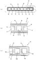
- FIG. 1 schematically shows an example of an aluminum extruded flat multi-hole pipe according to the present invention in the form of a cross section that is a cross section perpendicular to the longitudinal direction (tube axis direction).
- the flat multi-hole tube 10 according to the present invention is an extruded tube made of an aluminum material having a flat cross-sectional shape as a whole, and is composed of rectangular holes extending in parallel to the tube axis direction independently of each other.
- the thickness Ts is 90% or less, desirably 80% or less, and the lower limit thereof is preferably 1% or more, more preferably 5% or more. . That is, Ta ⁇ 0.9 ⁇ Ts and Ta ⁇ 0.01 ⁇ Ts are preferable.
- the thickness Ta of the sacrificial anode portion 18 exceeds 90% of the wall thickness Ts of the tube peripheral wall portion 14, Zn contained in the sacrificial anode portion 18 becomes thicker in the tube peripheral wall portion 14 during brazing heating.
- the pipe peripheral wall part 14 is liable to cause through corrosion, and the thickness of the pipe peripheral wall part 14 becomes too thin. As a result, problems such as a decrease in pressure resistance are caused.
- the sacrificial anode portion 18 is configured to be present on the outer peripheral surface side of the tube peripheral wall portion 14 at a predetermined thickness, whereby the pipe peripheral wall portion 14 is preferentially corroded by the sacrificial anode effect. As a result, excellent outer surface anticorrosive properties can be advantageously imparted to the outer peripheral portion of the pipe.
- the sacrificial anode portion 18 as described above is exposed over the entire tube circumferential length L of the flat multi-hole tube 10 or at least on the outer surface side of the tube peripheral wall portion 14 of a part of the flat portion.
- the exposure range is desirably configured to be exposed in a range corresponding to 50% or more and 100% or less of the total circumference L of the outer peripheral surface of the pipe, preferably 60% or more, more preferably 70% or more is advantageously employed.
- the corrosion resistance due to the sacrificial anode effect can be expressed more advantageously.
- the most preferable state is a case where the sacrificial anode portion 18 exists over the entire circumference L of the tube as shown in FIG.
- the thickness of the sacrificial anode portion 18 in the entire circumference L of the tube does not have to be the same over the entire exposed region.
- it is desirable that the sacrificial anode portion 18 is continuously exposed with respect to the entire circumference L of the tube, but is partially discontinuous or at a predetermined length. Even if it is exposed in a form extending in the pipe axis direction at a plurality of positions in the pipe circumferential direction, there is no problem.
- the aluminum sacrificial anode material used in the present invention is electrochemically less basic than the aluminum tube body material. Therefore, the potential difference between these materials exceeds 0 mV, but is preferably in the range of 5 mV to 300 mV. When this potential difference is 5 mV or more, the sacrificial anode effect is surely easily exhibited even in a more severe corrosive environment. On the other hand, when the potential difference exceeds 300 mV, the sacrificial anode effect becomes prominent, and problems such as severe corrosion consumption of the sacrificial anode material are caused.
- the sacrificial anode portion 18 is effective in the sacrificial anode effect due to being lower in potential than the flow passage 12 side portion made of the aluminum tube main body material in the tube peripheral wall portion 14, and the like. This is because the corrosion resistance of the inner surface of the flow path can be expressed more advantageously.
- surroundings of the flow path 12 containing the internal partition part 16 located between the adjacent flow paths 12 and 12 is conventionally used by extrusion process.
- Aluminum materials used in the production of flat multi-hole tubes can be used as they are, and for example, JIS-named A1000 series pure aluminum materials, A3000 series aluminum alloy materials, etc. can be used.
- a predetermined amount (for example, about 0.1 to 0.7 mass%) of Cu may be contained as an alloy component.
- the sacrificial anode material for providing the sacrificial anode portion 18 a known aluminum alloy material that is electrochemically lower than the above-described tube body material, in other words, has a lower natural potential, is used.
- the alloy component an aluminum alloy containing a predetermined amount of Zn, generally about 0.1 to 10% by mass, or the like is used.
- the flat multi-hole tube 10 uses the above-described tube body material and sacrificial anode material as the aluminum material to be extruded, and simultaneously extrudes these materials from the port hole die.
- the tube body material and the sacrificial anode material are generally used as a composite billet having a core-sheath structure.
- the hollow portion provided in the sacrificial anode material for example, a rectangular shape (including a curved corner portion), a circle, an oval, an ellipse, an oval and an oval
- a pipe body material having a cross-sectional shape corresponding to the hollow portion such as a combination of polygons and the like, and having a cross-sectional dimension optimized, and joining and integrating them by welding or the like, thereby
- a composite billet having a structure in which a sheath portion made of a sacrificial anode material is integrally formed around a core portion made of a main body material is used.
- a sheath billet is formed by providing a through-hole of a predetermined size at the center of a billet made of a sacrificial anode material, and
- a sheath billet is produced in the form of being divided into two, and the core is formed in the space of the two divided billets.
- the target composite billet it is possible to form the target composite billet by a method of fixing the whole by welding or the like and integrating them.
- a method of hot extrusion using a die having a plurality of extrusion ports, a so-called porthole die is applied to such a composite billet as in the case of manufacturing a conventional extruded flat multi-hole tube.
- the target extruded flat multi-hole tube can be obtained.
- a die having a long extrusion port arranged to correspond to a plurality of flow paths of the flat multi-hole tube the composite billet is arranged so that the longitudinal direction in the predetermined cross-sectional shape of the tube body material arranged inside the composite billet coincides with the longitudinal direction of the extrusion port of the die, Extrusion is performed.
- the sacrificial anode material arranged on the outer surface of the composite billet is effective over the circumference of the flat shape of the resulting flat multi-hole tube. Therefore, the sacrificial anode part can be advantageously exposed to the pipe outer peripheral surface of the pipe peripheral wall part.
- the aluminum extruded flat multi-hole tube according to the present invention as described above can be suitably used as a refrigerant flow path member in a heat exchanger.
- the aluminum extrusion flat multi-hole pipe according to the present invention as a refrigerant passage pipe, for example, a pair of aluminum header tanks arranged at a distance from each other, and a width direction ventilation direction between both header tanks And a plurality of extruded aluminum flat multi-hole tubes arranged in parallel with each other at intervals in the longitudinal direction of the header tank and connected to both header tanks, and adjacent flat multi-holes
- the heat exchanger is constructed in a structure comprising an aluminum side plate brazed to such fins.
- the aluminum extruded flat multi-hole pipe according to the present invention can be used as a refrigerant passage pipe in various known heat exchangers. That's where it is.
- a pair of header tanks in a heat exchanger distributes and flows refrigerant or coolant from one header tank to a flat multi-hole tube, and the other header tank is flat flat.
- the coolant or coolant that has flowed out of the hole tube is gathered.
- the header plate and the header plate are brazed oppositely, or the plate is bent into a tubular shape.
- an extruded tube extruded into a tubular shape or the like is used.
- Composite billets a to h and j made of a tube body material and a sacrificial anode material having the component composition (%: mass basis) shown in Table 1 below are manufactured, and each of them is a flat multi-hole tube by hot extrusion. A to H and J were obtained. Moreover, the single billet i of the component composition shown in following Table 1 was manufactured, and the flat multi-hole pipe I was obtained by the hot extrusion process. Then, using the obtained flat multi-hole tubes A to J, the following (1) measurement of the formation range of the sacrificial anode part, (2) potential measurement, and (3) evaluation of the outer surface anticorrosion property were performed.
- various pipe body billets of 90 mm ⁇ were produced by DC casting in accordance with a conventional method using the components for the pipe body materials in the composite billets a to h and j shown in Table 1.
- sacrificial anode billets prepared in the same manner using the components for sacrificial anode materials in the composite billets a to h and j shown in Table 1 above are variously combined in a circular dimension within the range of 5 mm to 85 mm to obtain a predetermined number.
- a through hole into which the processed tube body material billet can be inserted is formed in the central portion of the cross section of the sacrificial anode billet, and the tube body billet is inserted into the through hole, and the tubes are further inserted.
- the main body billet and the sacrificial anode billet are fixed and joined to each other in the longitudinal direction by MIG welding, and each composite billet ah and j has a cross-sectional shape as shown in FIG. It was produced as an integral composite billet 20.
- the simple billet i which consists of a pipe
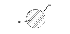
- the single billet i made of the tube body material component is a single billet shown as 30 in FIG. 3, which is the same as the conventional material not using the sacrificial anode billet.
- reference numerals 22 and 32 denote tube body billets
- reference numeral 24 denotes a sacrificial anode billet.
- the composite billet 20 or the single billet 30 thus obtained is heated to 500 ° C. with a billet heater, and then provided with an extrusion port for forming eight rectangular holes (eight flow paths).
- an extrusion port for forming eight rectangular holes (eight flow paths).
- the thickness of the sacrificial anode portion (18) formed on the tube peripheral wall portion (14) is the thickest. In the region, it is 80% or less of the thickness of the pipe peripheral wall (14), and more than 50% of the pipe outer peripheral length (L) of such a flat multi-hole pipe (10). It was observed that the sacrificial anode part (18) was exposed.
- the sacrificial anode portion (18) formed by the sacrificial anode billet in the longitudinal direction of the extrusion has a tube peripheral wall portion. It was also confirmed that (14) was stably exposed on the outer periphery of the tube.
- a flat multi-hole tube I obtained by carrying out hot extrusion using a porthole die using a single billet 30 composed of a billet composition i (Al-0.4% Cu) is a sacrificial anode billet. Since it was not used, no exposed portion of the sacrificial anode portion 18 was present on the outer peripheral surface of the tube. Moreover, in the flat multi-hole pipe J obtained from the composite billet j produced using the billet processed into a square shape of 60 mm ⁇ 60 mm as the pipe body billet, the sacrifice formed on the pipe peripheral wall portion (14) The thickness of the anode part (18) was 93% of the thickness of the pipe peripheral wall part (14) at the thickest part. Further, the ratio of the total length of the sacrificial anode portion (18) to the tube outer peripheral length (L) was 90%.
- brazing heating for fin bonding is assumed for flat multi-hole tubes A to H and flat multi-hole tubes I and J, respectively, when they are used as heat transfer tubes in a heat exchanger. And after heat-processing 600 degreeC * 3 minutes, they were cut
- the entire surface with the silicone resin except for the part where the lead wire for potential measurement is connected to one side of the cut end face leaving the exposed surface of the 10mm x 10mm sacrificial anode part (18) at the center in the width direction on the inner surface side.
- the test material for measuring the potential of the sacrificial anode part (18) leaves an exposed surface of the sacrificial anode material of 10 mm ⁇ 10 mm at the center in the width direction of the outer surface on one side of the peripheral wall part, All the portions except for the portion where the potential measurement lead wire was connected to one side of the cut end face were masked with silicone resin to be electrically insulated.
- a saturated KCl calomel electrode (SCE) is used as a reference electrode, while a 5% NaCl aqueous solution adjusted to pH 3 with acetic acid is used as a test solution.
- SCE saturated KCl calomel electrode
- a 5% NaCl aqueous solution adjusted to pH 3 with acetic acid is used as a test solution.
- a method of measuring each potential after immersing the test material in the solution for 24 hours while stirring at room temperature was employed.
- the potential difference between the sacrificial anode portion (18) (sacrificial anode material) and the tube body material of the flat multi-hole tubes A to H after the assumed brazing heating is as follows. 3 to 350 mV, all showing results having an effective sacrificial anode effect.
- the flat multi-hole tube I is composed of only the tube main body material similar to the conventional material without using the sacrificial anode material.
- the potential difference was 0 mV because it was a flat multi-hole tube.
- the sacrificial anode portion (18) (sacrificial anode material) of the flat multi-hole tube J after the assumed brazing heating was performed.
- the tube body material was 150 mV, which resulted in a sacrificial anode effect.
- brazing heating for fin bonding is assumed for flat multi-hole tubes A to H and flat multi-hole tubes I to J when they are used as heat transfer tubes in a heat exchanger. After heat treatment at 600 ° C. for 3 minutes, they were cut to a length of 100 mm in the longitudinal direction of extrusion, and both ends of the cut end face where the flow channel was exposed were masked with silicone resin.
- the test liquid used for the SWAAT test produced the artificial seawater by ASTM D1141, and added acetic acid to this artificial seawater, and adjusted it to pH3.
- the test condition was 0.5 hour spray-wet 1.5 hour as one cycle, and this cycle was repeated, and the outer surface anticorrosion evaluation test was conducted for three levels of 10 days, 20 days, and 30 days. .
- the cross-section was made with water-resistant paper for the maximum corroded part, and further mirror-finished by buffing.
- the corrosion situation of the pipe outer peripheral surface of the material was observed.
- penetration did not occur after 20 days, and if penetration was observed after 30 days or not penetrated ( ⁇ ), penetration after 10 days. When it did not occur and penetration was observed after 20 days, it was evaluated as ( ⁇ ), and when penetration was observed after 10 days, it was evaluated as (x).
- Table 4 below shows the results of evaluating the flat multi-hole tubes A to H and flat multi-hole tubes I to J by performing the above SWAAT test for 10, 20, and 30 days, respectively.
- the flat multi-hole tubes A to H had no through-holes penetrating the peripheral wall portion in the evaluation after 10 days of the SWAAT test. Further, in the evaluation after 20 days, in the flat multi-hole tubes B, C, F, and H, a through-hole penetrating the tube peripheral wall portion was confirmed. Furthermore, in the evaluation after 30 days, no through hole was observed in any flat multi-hole tube other than B, C, F, and H. Therefore, it was recognized that all of the flat multi-hole tubes A to H are effectively protected from the outer surface by the sacrificial anode effect due to the presence of the sacrificial anode portion (18).
- the flat multi-hole tube I is a flat multi-hole tube using only the tube main body material similar to the conventional material without using the sacrificial anode material, and therefore the SWAAT test is performed for 10, 20, and 30 days.
- the SWAAT test is performed for 10, 20, and 30 days.
- corrosion holes penetrating the pipe peripheral wall portion were generated in all the evaluations after the test.
- the sacrificial anode portion (18) does not exist on the outer peripheral portion of the tube, so the sacrificial anode effect cannot be obtained and the outer surface anticorrosive effect cannot be exhibited. It was recognized that penetration had occurred early.
- each of the penetrating portions is a portion where the sacrificial anode portion (18) is formed to exceed 90%, and the Zn contained in the sacrificial anode portion (18) is heat treatment corresponding to brazing heating. Occasionally, it diffused throughout the pipe wall (14), and as a result, the sacrificial anode part (18) was consumed at an early stage, and it was recognized that penetration occurred early.
Landscapes
- Engineering & Computer Science (AREA)
- Mechanical Engineering (AREA)
- Physics & Mathematics (AREA)
- Thermal Sciences (AREA)
- General Engineering & Computer Science (AREA)
- Chemical & Material Sciences (AREA)
- Materials Engineering (AREA)
- Metallurgy (AREA)
- Organic Chemistry (AREA)
- Geometry (AREA)
- Prevention Of Electric Corrosion (AREA)
- Heat-Exchange Devices With Radiators And Conduit Assemblies (AREA)
- Extrusion Of Metal (AREA)
Abstract
アルミニウム押出扁平多穴管において、その管外周面における防食性を効果的に高めること。 アルミニウム管本体材料と、それよりも電気化学的に卑なアルミニウム犠牲陽極材料とを用いて、押出加工により形成されるアルミニウム押出扁平多穴管10において、管周壁部14の外面側の管外周長Lの全周に亘って、又はその少なくとも平坦部の一部において、アルミニウム犠牲陽極材料を露呈せしめて、犠牲陽極部18を形成した。
Description
本発明は、外面防食性に優れたアルミニウム押出扁平多穴管とそれを用いてなるアルミニウム製熱交換器に係り、特に、熱交換器、中でもカーエアコン、ラジエータ等の自動車用熱交換器の伝熱管として好適に用いることが出来る、外面防食性に優れた熱交換器用アルミニウム押出扁平多穴管に関するものである。
従来より、アルミニウム材料の押出加工によって得られた、全体として扁平な横断面形状を呈するアルミニウム押出扁平多穴管は、自動車用熱交換器の冷媒通路管として使用されており、その冷媒通路に冷媒を流通せしめる一方、かかる冷媒通路管に対して直角な方向に、Al-Si系のアルミニウムろう材がクラッドされたアルミニウムフィンを組み付け、ろう付け固定することによって、熱交換器を構成し、そして、そのようなフィンに沿って、熱交換流体としての空気を流すことによって、冷媒と空気との間で熱交換が行われるようになっている。
また、そこで用いられる押出扁平多穴管としては、通常、アルミニウム若しくはアルミニウム合金のビレットをポートホール押出しして得られたものが採用されており、例えば、特開平6-142755号公報(特許文献1)、特開平5-222480号公報(特許文献2)、WO2013/125625(特許文献3)等には、各種の断面形態を呈する扁平多穴管が、明らかにされている。
しかしながら、かかる熱交換器の伝熱チューブとして用いられる、押出加工によって得られる扁平多穴管にあっては、一般に、その管外周部の表面には、何等防食処理が施されていないために、腐食が惹起されるという問題が内在しており、そしてそのような腐食の進行によって、管壁を貫通する腐食孔等が生じたりすると、熱交換器としての機能を全く喪失することとなるのである。
そこで、そのような熱交換器においては、押出扁平多穴管の管外表面の腐食を防止するために、従来から、押出扁平多穴管の表面に予め溶射或いは塗装等の方法によってZnを付着させておき、その後のろう付け加熱によりZnを拡散させ、その際、チューブ表層に形成されたZn拡散層が、それより深部のチューブ層に対して犠牲陽極として働き、管肉厚方向への腐食を抑制する手法が採用され、これによって、管の貫通寿命の延長が図られている。而して、この場合、押出扁平多穴管には、押し出された後に、Znの溶射或いは塗装等のZn付着工程が必要となり、更にその後に、ろう付けに必要となるフッ化物系フラックスの塗布工程、又は熱交換器コアに組み付けられた後にコア全体へのフラックス塗布工程が必要となるところから、製造工程の増加が避けられず、製造コストの上昇を招いてしまう等の問題が内在している。
このため、上記した押出扁平多穴管の一つとして、前記特開平5-222480号公報(特許文献2)にも明らかにされている如く、特定の成分組成のアルミニウム合金を単一で用いて、そのビレットを押出加工することによって、適切な防食性を具備する扁平多穴管を製造することが、一つの対策として提案されているのであるが、外面耐食性においては充分でなく、近年における高い防食性、コスト低減の要請に充分に応え得ないのみならず、チューブ全体を特定材質のアルミニウム合金にて構成するものであるところから、得られるチューブの特性が、かかる特定合金組成のアルミニウム合金によって制限を受けるという問題も内在している。
なお、特開昭63-97309号公報(特許文献4)には、アルミニウム芯材形成材料とAl-Si系のアルミニウムろう合金材料からなる表皮材形成材料とから構成された複合ビレットを用いて、同時に押出加工することによって、管周壁部の外面平坦部に対し、ろう材層がクラッドされてなるクラッド管を製造する方法が提案されているが、そのようなクラッド管には、犠牲陽極効果がなく、外面防食性を有していない。
かかる状況下、本発明者らは、アルミニウム材料の押出加工によって得られるアルミニウム押出扁平多穴管において、その管外周部の外面耐食性を向上させるべく鋭意検討した結果、押出加工されるアルミニウム材料として、通常のアルミニウム管本体材料と、Al-Zn系のアルミニウム犠牲陽極材料とを用いて、同時に熱間押出加工することにより、得られるアルミニウム押出扁平多穴管の管外周部に、かかるAl-Zn系のアルミニウム犠牲陽極材料を有利に露呈せしめて、犠牲陽極部を形成することが出来、そしてその犠牲陽極部の存在によって発揮される犠牲陽極効果により、アルミニウム押出扁平多穴管の管外周部に対して、優れた外面防食性を付与し得ることを見出したのである。
従って、本発明は、かくの如き知見に基づいて完成されたものであって、その解決課題とするところは、アルミニウム材料の押出加工によって得られる、全体として扁平な横断面形状を呈するアルミニウム押出扁平多穴管において、その管外周部における防食性を効果的に高めることにあり、また他の課題とするところは、管外周部の防食性を犠牲陽極効果によって著しく高めたアルミニウム押出扁平多穴管と、それを用いて得られる防食性に優れたアルミニウム製熱交換器を提供することにある。
そして、本発明にあっては、かくの如き課題の解決のために、アルミニウム材料の押出加工によって得られた、全体として扁平な横断面形状を呈する押出管であって、互いに独立して管軸方向に平行に延びる複数の流路を有し、且つそれら流路が、管軸方向に延びる内部隔壁部を介して、扁平形状の長手方向に配列せしめられているアルミニウム押出扁平多穴管にして、前記アルミニウム材料としてアルミニウム管本体材料とこのアルミニウム管本体材料よりも電気化学的に卑なアルミニウム犠牲陽極材料とを用いた押出加工によって形成されていると共に、管外周面の全域に、又は少なくとも管外周面における平坦部の一部に、前記アルミニウム犠牲陽極材料が露呈せしめられて、犠牲陽極部が形成されていることを特徴とする外面防食性に優れたアルミニウム押出扁平多穴管を、その要旨とするものである。
なお、かかる本発明において、有利には、管横断面における前記内部隔壁部以外の管周壁部において、前記犠牲陽極部が、該管周壁部の厚さの90%以下の割合で存在せしめられている。
また、本発明にあっては、上記した犠牲陽極部は、管横断面において、前記管外周面の周長の50%以上、100%以下の割合で存在させられて、管外周面に露呈せしめられていることが望ましいのである。
さらに、かかる本発明に従うアルミニウム押出扁平多穴管の望ましい態様の一つにあっては、前記アルミニウム犠牲陽極材料は、前記アルミニウム管本体材料よりも電気化学的に卑であり、その電位差は、5mV以上、300mV以下であることが好ましい。
更にまた、本発明に従うアルミニウム押出扁平多穴管の別の望ましい態様の一つにあっては、前記押出加工されるアルミニウム材料として、前記アルミニウム管本体材料と前記アルミニウム犠牲陽極材料とから構成される複合ビレットが用いられることとなる。
加えて、本発明の他の望ましい態様にあっては、前記複合ビレットが、前記アルミニウム管本体材料からなる芯ビレットと、該芯ビレットの周囲に位置する、前記アルミニウム犠牲陽極材料からなる鞘ビレットとからなる一体的な芯鞘構造を有している。
また、本発明に従うアルミニウム押出扁平多穴管にあっては、前記押出管が、一般に、ポートホールダイスを用いた前記アルミニウム材料の押出加工によって、形成されることとなる。
なお、本発明に従うアルミニウム押出扁平多穴管の好ましい態様の一つにあっては、前記アルミニウム管本体材料として、JIS称呼のA1000系純アルミニウム材料又はA3000系アルミニウム合金材料が用いられることとなる。
さらに、本発明の他の好ましい態様の一つにあっては、前記アルミニウム犠牲陽極材料として、Znを含有するアルミニウム合金材料が用いられる。
そして、本発明にあっては、上述の如き本発明に従うアルミニウム押出扁平多穴管と、このアルミニウム押出扁平多穴管の外面にろう付け接合されたアルミニウム製アウターフィンとを含んで構成されていることを特徴とするアルミニウム製熱交換器をも、その要旨とするものである。
このように、本発明に従う構成とされたアルミニウム押出扁平多穴管においては、その管外周面の全域に、又は少なくとも管外周面における平坦部の一部に、アルミニウム犠牲陽極材料からなる犠牲陽極部が露呈して存在せしめられているところから、かかる犠牲陽極材料に基づくところの犠牲陽極効果によって、外面防食性が効果的に高められ得ることとなるのであり、これによって、ラジエータやヒータ等、チューブ外面側の防食性に優れた熱交換器の伝熱管として有利に用いられ得ることとなったのである。
また、かかる本発明に従うアルミニウム押出扁平多穴管は、アルミニウム管本体材料とアルミニウム犠牲陽極材料とから構成され、それら2つの材料の同時押出加工によって形成されるものであるところから、管としての特性は、アルミニウム管本体材料にて確保しつつ、外面防食性は、アルミニウム犠牲陽極材料にて効果的に発揮せしめ得ることとなるのであって、これにより、目的とする押出扁平多穴管の設計自由度を有利に高め得る利点も有しているのである。
さらに、本発明に従うアルミニウム押出扁平多穴管を用いて、それとアルミニウム製アウターフィンとを組み付け、ろう付け加熱により接合して、構成されるアルミニウム製熱交換器にあっては、かかるアルミニウム押出扁平多穴管の優れた外面防食特性によって、熱交換器としての防食性も有利に高められ得るものとなるのである。
以下、本発明を更に具体的に明らかにするために、本発明の代表的な実施の形態について、図面を参照しつつ、詳細に説明することとする。
先ず、図1には、本発明に従うアルミニウム押出扁平多穴管の一例が、その長手方向(管軸方向)に対して直角な方向の断面となる横断面の形態において、模式的に示されている。そこにおいて、本発明に従う扁平多穴管10は、全体として扁平な横断面形状を呈するアルミニウム材料の押出管であって、互いに独立して管軸方向に平行に延びる矩形形状の空孔からなる流路12の複数を備えていると共に、それら複数の流路12が、管幅方向において、換言すれば扁平形状の長手方向(図において左右方向)に、所定間隔を隔てて配列せしめられてなる構造とされている。また、この扁平多穴管10の対応する上面と下面は、それぞれ平坦面とされて、そこに、従来と同様に、アルミニウム又はその合金からなる公知のプレートフィンやコルゲートフィンの如きアウターフィン(図示せず)が、ろう付け等の接合手法により取り付けられて、熱交換器として用いられ得るようになっている。なお、流路12の横断面形状は、ここでは、矩形形状とされているが、公知の円形、楕円形、三角形、台形等の形状、又は、それらを組み合わせた各種の形状を採用することが可能である。
そして、本発明にあっては、このような構造の扁平多穴管10において、図1の(a)から明らかな如く、その管周壁部14の外周面の全周に又は少なくとも平坦部の一部において(ここでは、全周において)、アルミニウム犠牲陽極材料からなる犠牲陽極部18が露呈せしめられるようにする一方、この犠牲陽極部18が露呈されていない部位、つまり隣り合う流路12、12の間に位置する内部隔壁部16を含む流路12の周囲には、通常のアルミニウム管本体材料が存在せしめられて、管としての特性を保持し得るようになっている。なお、ここで、管周壁部14は、図示の如く、扁平多穴管10の外周壁を構成するものであって、各流路12に対して外部隔壁部として機能するものである。
また、管周壁部14に形成される犠牲陽極部18は、図1の(b)に示される如く、管周壁部14に位置する場合においては、その厚さTaは、かかる管周壁部14の厚さTsの90%以下、望ましくは80%以下の割合において存在せしめられ、その下限としては、好ましくは1%以上、より好ましくは5%以上の割合となるように、存在せしめられることとなる。即ち、Ta≦0.9×Tsであり、またTa≧0.01×Tsであることが好ましいのである。なお、犠牲陽極部18の厚さTaが管周壁部14の肉厚Tsの90%を超えるようになると、犠牲陽極部18に含有されるZnが、ろう付け加熱時に管周壁部14の厚さ全体に拡散してしまい易くなって、犠牲陽極部18の腐食消耗後に、管周壁部14に貫通腐食が生じ易くなると共に、管周壁部14の厚さが薄くなり過ぎて、扁平多穴管10としての耐圧強度が低下する等の問題を惹起する。このように、犠牲陽極部18が、所定厚さにおいて、管周壁部14の外周面側に存在するように構成することにより、管周壁部14においては、犠牲陽極効果により優先して腐食が進行することとなり、以て管外周部に対して、優れた外面防食性が有利に付与され得ることとなるのである。
さらに、上述の如き犠牲陽極部18は、扁平多穴管10の管全周長Lの全体に亘って、又はその少なくとも平坦部の一部の管周壁部14の外面側において、露呈せしめられるものであって、その露呈範囲は、管外周面の全周長Lの50%以上、100%以下に相当する範囲において露呈するように構成されていることが望ましく、好ましくは60%以上、より好ましくは70%以上が有利に採用されることとなる。このように、犠牲陽極部18が管全周長Lの50%以上の領域に亘って露呈せしめられていることにより、犠牲陽極効果による防食性が、より有利に発現され得ることとなるのであり、特に、最も好ましい状態としては、図1の(a)に示される如く、犠牲陽極部18が管全周長Lの全体に亘って存在している場合である。なお、管全周長Lにおける犠牲陽極部18の厚さを露呈領域の全てに亘って同一とする必要はなく、例えば、図1の(c)に示されるように、管周方向に異なる厚さ割合を有する犠牲陽極部18が、露呈されるようにすることも可能である。更に、そのような犠牲陽極部18は、管全周長Lに対し、連続して露呈せしめられていることが望ましいのであるが、また部分的に非連続となっていたり、或いは所定長さにおいて管周方向の複数の位置で管軸方向に延びる形態において露呈せしめられていても、何等差し支えない。
なお、本発明において用いられるアルミニウム犠牲陽極材料は、アルミニウム管本体材料よりも、電気化学的に卑となるものである。従って、それら材料の電位差は、0mV超えとなるものであるが、好ましくは5mV以上、300mV以下の範囲である。この電位差が5mV以上となることで、より厳しい腐食環境下においても、確実に犠牲陽極効果を発揮しやすくなるのである。一方、電位差が300mV超えとなると、犠牲陽極効果が顕著となり、犠牲陽極材の腐食消耗が激しくなる等の問題が惹起される。このように、犠牲陽極部18が、管周壁部14における、アルミニウム管本体材料からなる流路12側部位等より、電位的に卑であることによって、有効な犠牲陽極効果が発揮され得て、流路内面の防食性が、より有利に発現され得ることとなるのである。
ところで、かくの如き扁平多穴管10において、隣り合う流路12、12の間に位置する内部隔壁部16を含む流路12の周囲を構成するアルミニウム管本体材料には、従来から押出加工による扁平多穴管の製造に用いられているアルミニウム材料がそのまま用いられ得るものであって、例えば、JIS称呼のA1000系純アルミニウム材料や、A3000系アルミニウム合金材料等を用いることが出来、更には、そのようなアルミニウム材料に、電位を貴にするため、合金成分としてCuが所定量(例えば、0.1~0.7質量%程度)含有せしめられていてもよい。また、犠牲陽極部18を与える犠牲陽極材料には、上記の管本体材料よりも電気化学的に卑となる、換言すれば自然電位が卑となる、公知のアルミニウム合金材料が用いられ、例えば、合金成分としてZnを所定量、一般に0.1~10質量%程度含むアルミニウム合金等が用いられることとなる。
そして、上述の如き本発明に従う扁平多穴管10は、押出加工されるアルミニウム材料として、上記した管本体材料と犠牲陽極材料とを用い、それら材料を、ポートホールダイスから同時押出加工することによって、製造されるものであるが、それら管本体材料と犠牲陽極材料とは、一般に、芯鞘構造の複合ビレットとして用いられることとなる。具体的には、犠牲陽極材料の内部(中心部)に設けた空洞部に、例えば矩形形状(角部が曲線状のものを含む)、円形、長円形、楕円形、長円形と楕円形との組合せ、多角形などの、該空洞部に対応した断面形状を有すると共に、断面寸法を最適化した管本体材料を配置せしめて、それらを溶接等によって接合して、一体化することにより、管本体材料からなる芯部分の周りに、犠牲陽極材料からなる鞘部分が一体的に形成されてなる構造の複合ビレットが、用いられるのである。
なお、このような複合ビレットの製造には、公知の各種の手段が採用され得、例えば、犠牲陽極材料からなるビレットの中心部に所定大きさの貫通孔を設けて鞘ビレットを形成し、そしてその貫通孔内に管本体材料からなる芯ビレットを挿入して、一体化せしめる手法の他、そのような鞘ビレットを二つ割りにした形態において作製し、そしてそれら二つ割りの鞘ビレットの空所に、芯ビレットを配置した形態において、全体を溶接等により固定して、一体化せしめる手法等によって、目的とする複合ビレットを形成することが可能である。
また、かかる複合ビレットには、従来の押出扁平多穴管の製造の場合と同様な、複数の押出口を有するダイス、所謂ポートホールダイスを用いて、熱間押出加工する手法が適用され、これによって、目的とする押出扁平多穴管を得ることが出来ることとなるのであるが、その際、扁平多穴管の複数の流路に対応するように配設された長手の押出口を有するダイスに対して、複合ビレットの内部に配置せしめられた管本体材料の所定の断面形状における長手方向が、かかるダイスの押出口の長手方向と一致するように、当該複合ビレットを配置して、熱間押出加工が実施されるのである。このような複合ビレットのポートホールダイスに対する押出形態の採用により、得られる扁平多穴管の扁平形状の外周部に位置する管周長に亘り、複合ビレットの外面に配置された犠牲陽極材料を効果的に配分せしめ得て、犠牲陽極部を管周壁部の管外周面に有利に露出せしめ得ることとなる。
ところで、上述の如き本発明に従うアルミニウム押出扁平多穴管は、熱交換器における冷媒流路部材として、好適に用いられ得るものである。そして、本発明に従うアルミニウム押出扁平多穴管を冷媒通路管として用いる場合においては、例えば、互いに間隔を置いて配置された一対のアルミニウム製ヘッダータンクと、両ヘッダータンク間に、幅方向を通風方向に平行に向けた状態で、ヘッダータンクの長手方向に間隔を置いて互いに平行に配列され、かつ両端部が両ヘッダータンクに接続された複数のアルミニウム押出扁平多穴管と、隣り合う扁平多穴管同士の間及び両端の扁平多穴管の外側に配置されて、それら扁平多穴管にろう付け固定された、アウターフィンであるアルミニウム製コルゲート状フィンと、両端のコルゲート状フィンの外側に配置されて、かかるフィンにろう付けされたアルミニウム製サイドプレートとを備えてなる構造において、熱交換器が構成されることとなるが、勿論、そのような構造の熱交換器の他にも、公知の各種の熱交換器における冷媒通路管として、本発明に従うアルミニウム押出扁平多穴管を用いることが出来ることは、言うまでもないところである。
なお、よく知られているように、熱交換器における一対のヘッダータンクは、一方のヘッダータンクから扁平多穴管に冷媒若しくは冷却液を分配して流入させると共に、他方のヘッダータンクは、扁平多穴管から流出した冷媒若しくは冷却液を集合させるようにしたものであって、例えば、公知の如く、ヘッダープレートとヘッダープレートとを対向してろう付けしたものや、板を管状に曲げ成形して、その管状とされたものの合わせ部を溶接又はろう付けして構成されたものの他、管状に押し出された押出管等が、用いられることとなる。
以上、本発明の代表的な実施形態について詳述してきたが、それは、あくまでも例示に過ぎないものであって、本発明は、そのような実施形態に係る具体的な記述によって何等限定的に解釈されるものではないことが、理解されるべきである。
そして、本発明が、当業者の知識に基づいて、種々なる変更、修正、改良等を加えた態様において実施され得るものであり、またそのような実施の態様が、本発明の趣旨を逸脱しない限りにおいて、何れも、本発明の範疇に属するものであることは、言うまでもないところである。
以下に、本発明の代表的な実施例を示し、本発明を更に具体的に明らかにすることとするが、本発明が、そのような実施例の記載によって、何等の制約をも受けるものでないことも、また、理解されるべきである。
下記表1に示される成分組成(%:質量基準)を有する管本体材料と犠牲陽極材料からなる複合ビレットa~h及びjを製作し、それらの熱間押出加工によって、それぞれ、扁平多穴管A~H及びJを得た。また、下記表1に示される成分組成の単体ビレットiを製作し、その熱間押出加工によって、扁平多穴管Iを得た。そして、それら得られた扁平多穴管A~Jを用いて、以下の(1)犠牲陽極部の形成範囲の測定、(2)電位測定、及び(3)外面防食性評価を実施した。

具体的には、先ず、かかる表1に示される複合ビレットa~h及びjにおける管本体材料用成分を用いて、常法に従って、DC鋳造により、90mmφの各種の管本体用ビレットをそれぞれ作製した。一方、上記表1に示される複合ビレットa~h及びjにおける犠牲陽極材料用成分を用いて同様に作製した犠牲陽極用ビレットを、円形の寸法が5mm~85mmの範囲内において種々組み合せて、所定の寸法に成形・加工した。そして、前記犠牲陽極用ビレットの断面中央部に、かかる加工済みの管本体材料用ビレットを挿入し得る貫通孔を形成せしめて、その貫通孔内に、管本体用ビレットを嵌入し、更にそれら管本体用ビレットと犠牲陽極用ビレットとを、それらの長手方向両端面において、MIG溶接により固定・接合せしめて、それぞれの複合ビレットa~h及びjを、図2に示される如き断面形態を有する、一体的な複合ビレット20として、作製した。また、上記表1に示される管本体材料用成分からなる単体ビレットiを作製した。この管本体材料用成分からなる単体ビレットiは、犠牲陽極用ビレットを用いていない従来材と同様な、図3において、30として示される単体ビレットである。なお、図2、3において、22及び32は、管本体用ビレットであり、24は犠牲陽極用ビレットである。
次いで、かかる得られた複合ビレット20又は単体ビレット30を、ビレットヒータにて500℃まで加熱した後、8穴の矩形穴(8個の流路)を形成するための押出口を備えた、従来と同様なポートホールダイスを用いて、熱間押出加工することにより、図1に示される如き8穴の扁平多穴管A~H及びI~J(全体厚さ:2.0mm、扁平方向の幅:16mm、管周壁部及び内部隔壁部の肉厚:0.25mm)を、それぞれ製造した。
(1)犠牲陽極部の形成範囲の測定
かくして得られた8穴の各種の扁平多穴管(10)について、それらを押出長手方向の1/2の位置でそれぞれ切断して、その断面を観察した。即ち、かかる断面のミクロ組織を倍率25倍で撮影した写真を用いて、その犠牲陽極部(18)の領域を物差しで計測することにより、犠牲陽極部(18)の形成範囲を測定した。そして、このような犠牲陽極部(18)の形成範囲の測定において、犠牲陽極部(18)の厚さ(最大厚さ)が、管周壁部(14)の厚さの90%以下である場合は(〇)とし、90%を超える場合は(×)として、評価した。更に、管周壁部(14)の管外周長(L)に対する犠牲陽極部(18)の露呈部位の長さの割合(扁平多穴管の外周面に犠牲陽極材料部(18)が形成された範囲の合計長さ)が50%以上である場合は(〇)とし、管外周長(L)が0%以上、50%未満である場合は(×)として、評価した。下記の表2には、扁平多穴管A~H及び扁平多穴管I及びJについて、上記の犠牲陽極部(18)の形成範囲を測定した結果が、管周壁部(14)の厚さに対する犠牲陽極部(18)の最大厚さとなる部位の比率及び管外周長(L)に対する犠牲陽極部(18)の合計長さの割合において、示されている。
かくして得られた8穴の各種の扁平多穴管(10)について、それらを押出長手方向の1/2の位置でそれぞれ切断して、その断面を観察した。即ち、かかる断面のミクロ組織を倍率25倍で撮影した写真を用いて、その犠牲陽極部(18)の領域を物差しで計測することにより、犠牲陽極部(18)の形成範囲を測定した。そして、このような犠牲陽極部(18)の形成範囲の測定において、犠牲陽極部(18)の厚さ(最大厚さ)が、管周壁部(14)の厚さの90%以下である場合は(〇)とし、90%を超える場合は(×)として、評価した。更に、管周壁部(14)の管外周長(L)に対する犠牲陽極部(18)の露呈部位の長さの割合(扁平多穴管の外周面に犠牲陽極材料部(18)が形成された範囲の合計長さ)が50%以上である場合は(〇)とし、管外周長(L)が0%以上、50%未満である場合は(×)として、評価した。下記の表2には、扁平多穴管A~H及び扁平多穴管I及びJについて、上記の犠牲陽極部(18)の形成範囲を測定した結果が、管周壁部(14)の厚さに対する犠牲陽極部(18)の最大厚さとなる部位の比率及び管外周長(L)に対する犠牲陽極部(18)の合計長さの割合において、示されている。
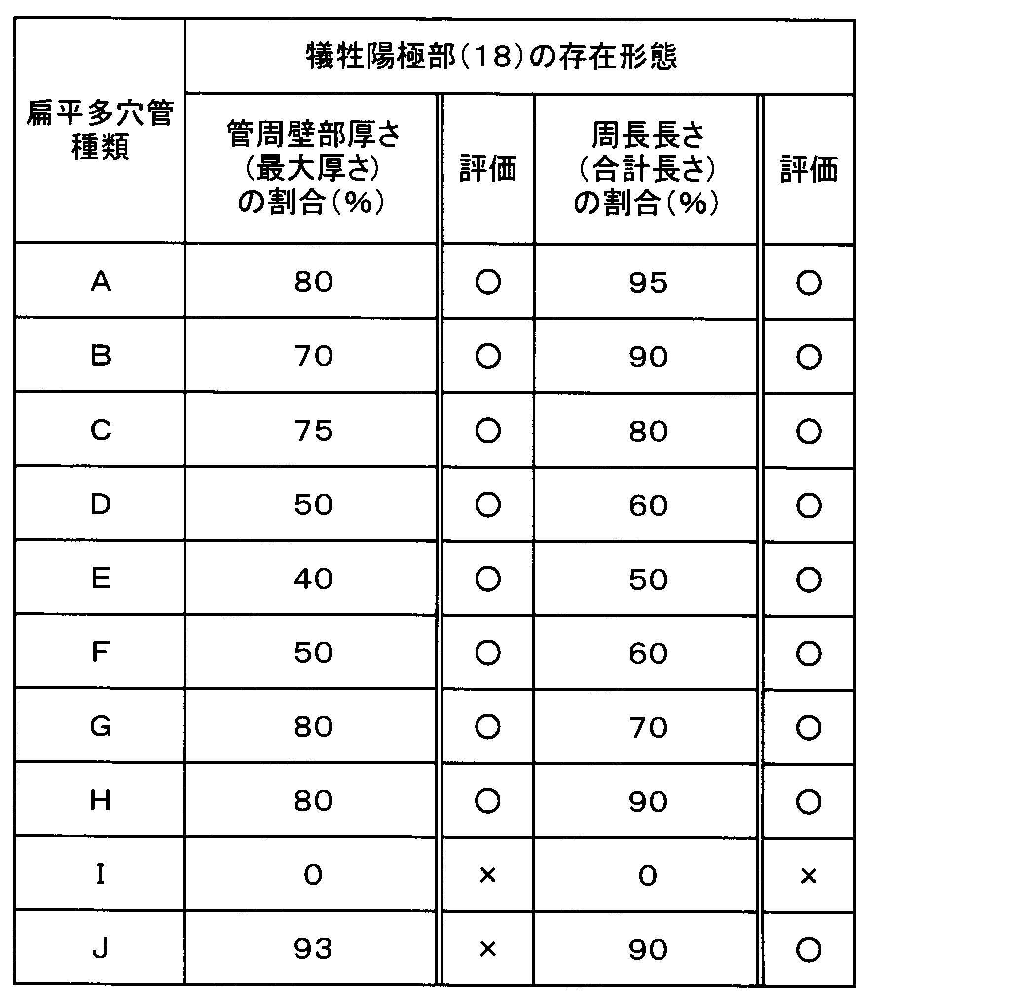
かかる断面観察の結果、上記の押出加工によって得られた扁平多穴管A~Hにおいては、管周壁部(14)に形成される犠牲陽極部(18)の厚さは、何れも、最も厚い部位で、管周壁部(14)の厚さの80%以下であり、更に、そのような扁平多穴管(10)の管外周長(L)に対して、50%を超える長さ範囲において、犠牲陽極部(18)が露呈されていることが認められた。
また、このように熱間押出して得られた扁平多穴管(10)にあっては、その押出長手方向において、犠牲陽極用ビレットにて形成される犠牲陽極部(18)が、管周壁部(14)の管外周部に安定して露呈せしめられていることも、確認された。
一方、ビレット組成i(Al-0.4%Cu)からなる単体ビレット30を用いて、ポートホールダイスによる熱間押出加工を実施して得られた扁平多穴管Iは、犠牲陽極用ビレットを用いていないため、犠牲陽極部18の露呈部位は、管外周面に何等存在していなかった。また、管本体用ビレットとして、60mm×60mmの正方形状に加工されたビレットを用いて作製された複合ビレットjから得られた扁平多穴管Jにおいて、管周壁部(14)に形成された犠牲陽極部(18)の厚さは、最も厚い部位で、管周壁部(14)の厚さの93%となった。また、管外周長(L)に対する犠牲陽極部(18)の合計長さの割合は、90%となるものであった。
(2)電位測定
上記で得られた、扁平多穴管A~H及び扁平多穴管I及びJを用いて、それぞれ、管本体材料と犠牲陽極材料の電位を測定した。なお、扁平多穴管Iは管本体材料のみで構成された単一ビレットから製造されており、犠牲陽極部(18)は形成されていないものである。
上記で得られた、扁平多穴管A~H及び扁平多穴管I及びJを用いて、それぞれ、管本体材料と犠牲陽極材料の電位を測定した。なお、扁平多穴管Iは管本体材料のみで構成された単一ビレットから製造されており、犠牲陽極部(18)は形成されていないものである。
具体的には、扁平多穴管A~H及び扁平多穴管I及びJに対して、それぞれ、それらが熱交換器における伝熱管として用いられる際の、フィン接合のためのろう付け加熱を想定して、600℃×3分の加熱処理を施した後、それらを押出長手方向に40mmの長さでそれぞれ切断した。そして、管本体材料の電位を測定する供試材は、その扁平形状の長手方向(管軸に直角な方向)に延びる切断面において、厚さ1/2の位置で切断し、その半体の内表面側の幅方向中央部に10mm×10mmの犠牲陽極部(18)の露出面を残して、切断端面の片側に電位測定用のリード線を接続する部位を除く全てをシリコーン樹脂にてマスキングすることにより、電気的に絶縁した。また、犠牲陽極部(18)(犠牲陽極材料)の電位を測定する供試材は、その周壁部の片側の外表面の幅方向中央部に10mm×10mmの犠牲陽極材料の露出面を残し、切断端面の片側に電位測定用のリード線を接続する部位を除く全てをシリコーン樹脂にてマスキングすることにより、電気的に絶縁した。
また、電位の測定方法としては、参照電極として、飽和KClカロメル電極(SCE:Saturated Calomel Electrode )を用いる一方、試験溶液としては、酢酸にてpH3に調整された5%NaCl水溶液を用い、それを室温下にて撹拌しつつ、その溶液に供試材を24h浸漬した後、それぞれの電位を測定する方法を、採用した。
そして、上記測定で得られた管本体材料と犠牲陽極材料との電位差の結果を、下記表3に示す。なお、かかる管本体材料と犠牲陽極材料との電位差が、5mV以上、300mV以下の場合は(◎)とし、その電位差が0mVを超え、5mV未満の場合及び300mVを超える場合は(〇)とし、0mVの場合は(×)として、評価した。
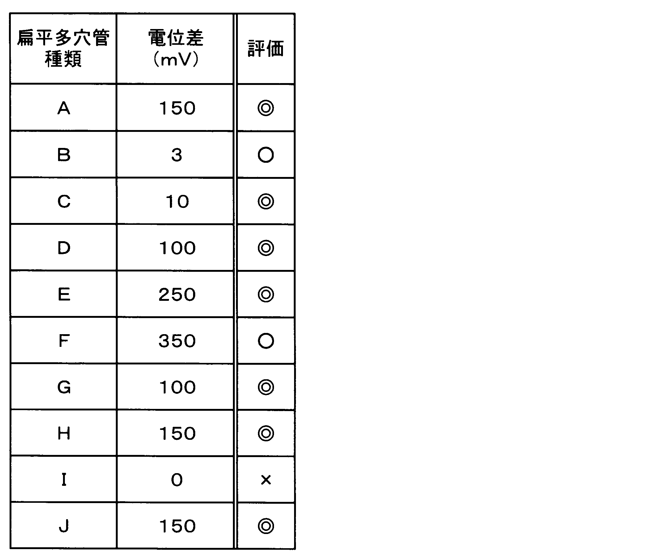
かかる表3に示される電位測定結果より明らかな如く、扁平多穴管A~Hの、想定されるろう付け加熱後における犠牲陽極部(18)(犠牲陽極材料)と管本体材料との電位差は、3~350mVであり、何れも、有効な犠牲陽極効果を有する結果を示すものであった。
これに対して、扁平多穴管Iを供試材とした場合にあっては、当該扁平多穴管Iが、犠牲陽極材料を用いることなく、従来材と同様の、管本体材料のみで構成された扁平多穴管であるところから、その電位差は0mVであった。
また、扁平多穴管Jを供試材として、上記と同様な電位測定を行ったところ、当該扁平多穴管Jの、想定されるろう付け加熱後における犠牲陽極部(18)(犠牲陽極材料)と管本体材料との電位差は150mVとなり、犠牲陽極効果を有する結果となった。
(3)外面防食性評価
上記で得られた、扁平多穴管A~Hと扁平多穴管I及びJとを供試材として、それぞれ、ASTM-G85-Annex A3に規定されるSWAAT試験を実施し、それぞれの外面防食の効果を検証した。このSWAAT試験は、定温度(49℃)条件下で、人工海水噴霧と湿潤環境を繰返して曝露負荷することによって、外面防食性を評価するものである。また、腐食試験期間は10日、20日及び30日間の3水準の期間とし、貫通が無いものは(○)と評価し、貫通しているものを(×)と評価した。
上記で得られた、扁平多穴管A~Hと扁平多穴管I及びJとを供試材として、それぞれ、ASTM-G85-Annex A3に規定されるSWAAT試験を実施し、それぞれの外面防食の効果を検証した。このSWAAT試験は、定温度(49℃)条件下で、人工海水噴霧と湿潤環境を繰返して曝露負荷することによって、外面防食性を評価するものである。また、腐食試験期間は10日、20日及び30日間の3水準の期間とし、貫通が無いものは(○)と評価し、貫通しているものを(×)と評価した。
具体的には、扁平多穴管A~H及び扁平多穴管I~Jに対して、それらが熱交換器における伝熱管として用いられる際の、フィン接合のためのろう付け加熱を想定して、600℃×3分の加熱処理を施した後、それらを押出長手方向に100mmの長さで切断し、流路が露出した切断端面の両端をシリコーン樹脂にてマスキングした。また、SWAAT試験に用いた試験液は、ASTM D1141による人工海水を作製し、この人工海水に酢酸を添加してpH3に調整した。また、試験条件は0.5時間噴霧-湿潤1.5時間を1サイクルとし、このサイクルを繰り返し、10日、20日及び30日の3水準の期間での外面防食性の評価試験を実施した。
そして、かかる外面防食性の評価試験の終了した供試材に対しては、両端部のシリコーンシーラント樹脂を剥離した後、ヒータで昇温したリン酸クロム酸液に投入して、供試材表面の腐食生成物を除去して、供試材表面における貫通孔の有無を調べた。具体的には、扁平多穴管のそれぞれの流路に、浸透性の高い着色された探傷液を滴下し、扁平多穴管の内面からその探傷液の染み出しを確認する方法により貫通孔の有無を調べた。更に、その貫通孔を調べた供試材を、埋め込み樹脂で埋包した後、最大腐食部に対して耐水ペーパーによる断面出しを施し、更にバフ研磨にて鏡面仕上げすることにより、それぞれの供試材の管外周面の腐食状況を観察した。なお、上記試験で使用された供試材のSWAAT試験において、20日後では貫通は発生せず、30日後に貫通が認められた場合或いは未貫通の場合は(◎)とし、10日後では貫通は発生せず、20日後に貫通が認められた場合は(○)とし、10日後に貫通が認められた場合を(×)として、評価した。
以下の表4には、扁平多穴管A~H及び扁平多穴管I~Jについて、上記のSWAAT試験を10、20、及び30日間実施して評価した結果が、それぞれ示されている。
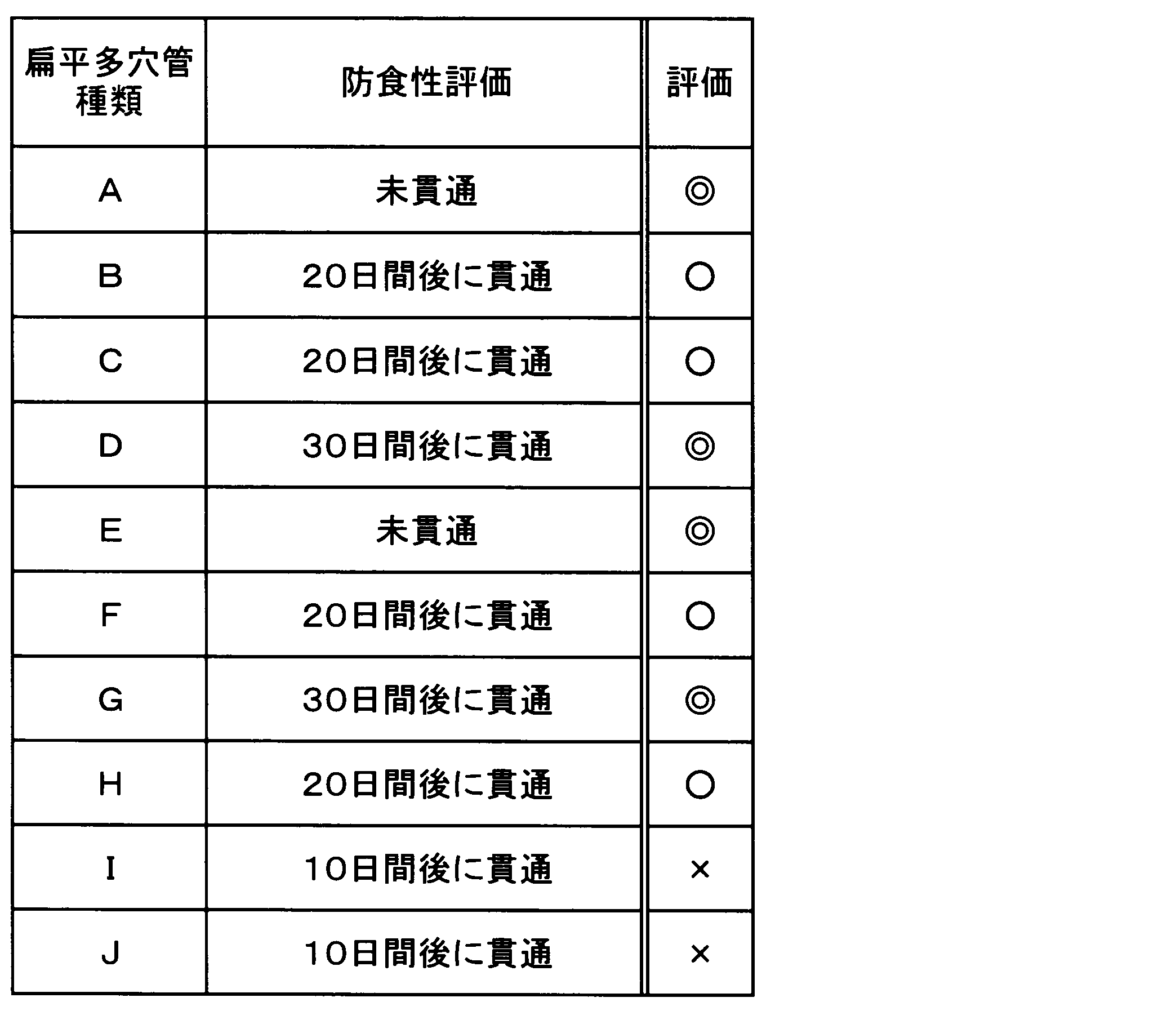
かかる表4の結果より明らかな如く、扁平多穴管A~Hは、SWAAT試験の10日後の評価において、管周壁部を貫通する貫通孔が生じていないことが認められた。また、20日後の評価においては、扁平多穴管B、C、F、Hにおいて、管周壁部を貫通する貫通孔が確認された。更に、30日後の評価においては、B、C、F、H以外の何れの扁平多穴管にも、貫通孔は認められなかった。従って、扁平多穴管A~Hは、何れも、犠牲陽極部(18)の存在による犠牲陽極効果によって、有効な外面防食が施されていることが、認められた。
これに対して、扁平多穴管Iは、犠牲陽極材料を用いることなく、従来材と同様の管本体材料のみを用いた扁平多穴管であるため、SWAAT試験を10、20、及び30日間実施したところ、全ての試験後の評価において、管周壁部を貫通する腐食孔が生じていることが、認められた。これは、本発明に係る扁平多穴管の如く、犠牲陽極部(18)が管外周部に存在しないために、犠牲陽極効果が得られず、外面防食効果が発揮され得なかったことにより、早期に貫通が生じたものと認められた。
また、扁平多穴管Jは、上記と同様なSWAAT試験を10、20、及び30日間実施したところ、全ての試験後の評価において、管周壁部を貫通する腐食孔が生じていることが認められた。この貫通部は、何れも、犠牲陽極部(18)が90%を超えて形成されている部位であり、かかる犠牲陽極部(18)に含有されるZnが、ろう付け加熱に相当する加熱処理時に管周壁部(14)全体に拡散してしまい、その結果、犠牲陽極部(18)が早期に消耗したために、早期に貫通が生じたものと認められた。
10 扁平多穴管 12 流路(空孔)
14 管周壁部 16 内部隔壁部
18 犠牲陽極部 20 複合ビレット
22 管本体ビレット 24 犠牲陽極ビレット
30 単体ビレット 32 管本体ビレット
14 管周壁部 16 内部隔壁部
18 犠牲陽極部 20 複合ビレット
22 管本体ビレット 24 犠牲陽極ビレット
30 単体ビレット 32 管本体ビレット
Claims (10)
- アルミニウム材料の押出加工によって得られた、全体として扁平な横断面形状を呈する押出管であって、互いに独立して管軸方向に平行に延びる複数の流路を有し、且つそれら流路が、管軸方向に延びる内部隔壁部を介して、扁平形状の長手方向に配列せしめられているアルミニウム押出扁平多穴管にして、
前記アルミニウム材料としてアルミニウム管本体材料とこのアルミニウム管本体材料よりも電気化学的に卑なアルミニウム犠牲陽極材料とを用いた押出加工によって形成されていると共に、管外周面の全域に、又は少なくとも管外周面における平坦部の一部に、前記アルミニウム犠牲陽極材料が露呈せしめられて、犠牲陽極部が形成されていることを特徴とする外面防食性に優れたアルミニウム押出扁平多穴管。 - 管横断面における前記内部隔壁部以外の管周壁部において、前記犠牲陽極部が、該管周壁部の厚さの90%以下の割合で存在せしめられている請求項1に記載の外面防食性に優れたアルミニウム押出扁平多穴管。
- 前記犠牲陽極部が、管横断面において、前記管外周面の周長の50%以上、100%以下の割合で存在せしめられている請求項1又は請求項2に記載の外面防食性に優れたアルミニウム押出扁平多穴管。
- 前記アルミニウム犠牲陽極材料と前記アルミニウム管本体材料との電位差は、5mV以上、300mV以下であることを特徴とする請求項1乃至請求項3の何れか1項に記載の外面防食性に優れたアルミニウム押出扁平多穴管。
- 前記押出加工されるアルミニウム材料が、前記アルミニウム管本体材料と前記アルミニウム犠牲陽極材料とから構成される複合ビレットである請求項1乃至請求項4の何れか1項に記載の外面防食性に優れたアルミニウム押出扁平多穴管。
- 前記複合ビレットが、前記アルミニウム管本体材料からなる芯ビレットと、該芯ビレットの周囲に位置する、前記アルミニウム犠牲陽極材料からなる鞘ビレットとからなる一体的な芯鞘構造を有している請求項5に記載の外面防食性に優れたアルミニウム押出扁平多穴管。
- 前記押出管が、ポートホールダイスを用いた前記アルミニウム材料の押出加工によって形成されている請求項1乃至請求項6の何れか1項に記載の外面防食性に優れたアルミニウム押出扁平多穴管。
- 前記アルミニウム管本体材料が、JIS称呼のA1000系純アルミニウム材料又はA3000系アルミニウム合金材料である請求項1乃至請求項7の何れか1項に記載の外面防食性に優れたアルミニウム押出扁平多穴管。
- 前記アルミニウム犠牲陽極材料が、Znを含有するアルミニウム合金材料である請求項1乃至請求項8の何れか1項に記載の外面防食性に優れたアルミニウム押出扁平多穴管。
- 請求項1乃至請求項9の何れか1項に記載のアルミニウム押出扁平多穴管と、該アルミニウム押出扁平多穴管の外面にろう付け接合されたアルミニウム製アウターフィンとを含んで構成されていることを特徴とするアルミニウム製熱交換器。
Priority Applications (3)
| Application Number | Priority Date | Filing Date | Title |
|---|---|---|---|
| CN201880011537.4A CN110290884A (zh) | 2017-02-13 | 2018-02-08 | 外表面防腐蚀性优异的铝挤出扁平多孔管及使用其而成的铝制热交换器 |
| JP2018567476A JPWO2018147348A1 (ja) | 2017-02-13 | 2018-02-08 | 外面防食性に優れたアルミニウム押出扁平多穴管及びそれを用いてなるアルミニウム製熱交換器 |
| DE112018000792.8T DE112018000792T5 (de) | 2017-02-13 | 2018-02-08 | Stranggepresste flache perforierte Aluminiumröhre mit hervorragenderAußenoberflächenkorrosionsbeständigkeit, und unter Verwendung davon erhaltenerAluminiumwärmetauscher |
Applications Claiming Priority (2)
| Application Number | Priority Date | Filing Date | Title |
|---|---|---|---|
| JP2017023867 | 2017-02-13 | ||
| JP2017-023867 | 2017-02-13 |
Publications (1)
| Publication Number | Publication Date |
|---|---|
| WO2018147348A1 true WO2018147348A1 (ja) | 2018-08-16 |
Family
ID=63107580
Family Applications (1)
| Application Number | Title | Priority Date | Filing Date |
|---|---|---|---|
| PCT/JP2018/004301 Ceased WO2018147348A1 (ja) | 2017-02-13 | 2018-02-08 | 外面防食性に優れたアルミニウム押出扁平多穴管及びそれを用いてなるアルミニウム製熱交換器 |
Country Status (4)
| Country | Link |
|---|---|
| JP (1) | JPWO2018147348A1 (ja) |
| CN (1) | CN110290884A (ja) |
| DE (1) | DE112018000792T5 (ja) |
| WO (1) | WO2018147348A1 (ja) |
Citations (5)
| Publication number | Priority date | Publication date | Assignee | Title |
|---|---|---|---|---|
| JPH05164496A (ja) * | 1991-12-17 | 1993-06-29 | Tokyo Gas Co Ltd | オープンラック型気化器用フィンチューブ |
| JPH06142755A (ja) * | 1992-11-05 | 1994-05-24 | Nippondenso Co Ltd | 多穴管押出用ダイスおよびこの多穴管押出用ダイスを用いて製造された多穴管 |
| US20060118282A1 (en) * | 2004-12-03 | 2006-06-08 | Baolute Ren | Heat exchanger tubing by continuous extrusion |
| WO2009020171A1 (ja) * | 2007-08-07 | 2009-02-12 | Showa Denko K.K. | 熱交換器用部材の製造方法および熱交換器用部材 |
| WO2017026510A1 (ja) * | 2015-08-11 | 2017-02-16 | 株式会社Uacj | 内面防食性に優れたアルミニウム押出扁平多穴管及びそれを用いてなるアルミニウム製熱交換器 |
Family Cites Families (2)
| Publication number | Priority date | Publication date | Assignee | Title |
|---|---|---|---|---|
| JP2012007872A (ja) * | 2010-05-24 | 2012-01-12 | Kobe Steel Ltd | 複層伝熱管、複層伝熱管の製造方法、及びその製造方法に用いられる成形治具 |
| CN103658216B (zh) * | 2013-11-29 | 2016-03-09 | 中国船舶重工集团公司第七二五研究所 | 一种开架式气化器用铝合金翅片管挤压模具 |
-
2018
- 2018-02-08 JP JP2018567476A patent/JPWO2018147348A1/ja active Pending
- 2018-02-08 DE DE112018000792.8T patent/DE112018000792T5/de not_active Withdrawn
- 2018-02-08 WO PCT/JP2018/004301 patent/WO2018147348A1/ja not_active Ceased
- 2018-02-08 CN CN201880011537.4A patent/CN110290884A/zh active Pending
Patent Citations (5)
| Publication number | Priority date | Publication date | Assignee | Title |
|---|---|---|---|---|
| JPH05164496A (ja) * | 1991-12-17 | 1993-06-29 | Tokyo Gas Co Ltd | オープンラック型気化器用フィンチューブ |
| JPH06142755A (ja) * | 1992-11-05 | 1994-05-24 | Nippondenso Co Ltd | 多穴管押出用ダイスおよびこの多穴管押出用ダイスを用いて製造された多穴管 |
| US20060118282A1 (en) * | 2004-12-03 | 2006-06-08 | Baolute Ren | Heat exchanger tubing by continuous extrusion |
| WO2009020171A1 (ja) * | 2007-08-07 | 2009-02-12 | Showa Denko K.K. | 熱交換器用部材の製造方法および熱交換器用部材 |
| WO2017026510A1 (ja) * | 2015-08-11 | 2017-02-16 | 株式会社Uacj | 内面防食性に優れたアルミニウム押出扁平多穴管及びそれを用いてなるアルミニウム製熱交換器 |
Also Published As
| Publication number | Publication date |
|---|---|
| DE112018000792T5 (de) | 2019-10-31 |
| CN110290884A (zh) | 2019-09-27 |
| JPWO2018147348A1 (ja) | 2019-11-21 |
Similar Documents
| Publication | Publication Date | Title |
|---|---|---|
| JP6799951B2 (ja) | 内面防食性に優れたアルミニウム押出扁平多穴管及びそれを用いてなるアルミニウム製熱交換器 | |
| CN101676667B (zh) | 铝合金制热交换器及其制造方法 | |
| US10386134B2 (en) | Heat transfer tube and method for producing same | |
| EP2565573A1 (en) | Heat exchanger and method for producing heat exchanger | |
| JP2009041880A (ja) | 給湯機用水熱交換器 | |
| CN100470185C (zh) | 热交换器及其制造方法 | |
| US9581398B2 (en) | Heat exchanger | |
| WO2017026510A1 (ja) | 内面防食性に優れたアルミニウム押出扁平多穴管及びそれを用いてなるアルミニウム製熱交換器 | |
| US20210207901A1 (en) | Aluminum alloy heat exchanger | |
| JP6003778B2 (ja) | 熱交換器の製造方法 | |
| WO2018147375A1 (ja) | ろう付け性及び外面防食性に優れたアルミニウム押出扁平多穴管及びそれを用いてなるアルミニウム製熱交換器 | |
| WO2018147348A1 (ja) | 外面防食性に優れたアルミニウム押出扁平多穴管及びそれを用いてなるアルミニウム製熱交換器 | |
| WO2018147349A1 (ja) | 内外面防食性に優れたアルミニウム押出扁平多穴管及びそれを用いてなるアルミニウム製熱交換器 | |
| JP6959111B2 (ja) | アルミニウム押出管製扁平多流路管及びその製造方法 | |
| JP2019070499A (ja) | 熱交換器の製造方法 | |
| WO2016022812A1 (en) | Brazed heat exchanger and manufacturing process | |
| JP6329924B2 (ja) | 熱交換器用アルミニウム合金管および熱交換器コア | |
| JP2019158186A (ja) | 内面防食性に優れたアルミニウム押出扁平多穴管及びそれを用いてなるアルミニウム製熱交換器 | |
| CN103857973A (zh) | 微通道加热交换器合金系统 | |
| US12287161B2 (en) | Aluminum alloy heat exchanger | |
| JP6518804B2 (ja) | 熱交換器用アルミニウム合金管の製造方法 | |
| JPH11106855A (ja) | 熱交換器 | |
| JP2019035567A (ja) | アルミニウム製熱交換器及びその製造方法 | |
| US20190072344A1 (en) | Heat exchanger | |
| CN117002104A (zh) | 一种用于换热器的换热管及换热器 |
Legal Events
| Date | Code | Title | Description |
|---|---|---|---|
| 121 | Ep: the epo has been informed by wipo that ep was designated in this application |
Ref document number: 18750756 Country of ref document: EP Kind code of ref document: A1 |
|
| WWE | Wipo information: entry into national phase |
Ref document number: 2018567476 Country of ref document: JP |
|
| 122 | Ep: pct application non-entry in european phase |
Ref document number: 18750756 Country of ref document: EP Kind code of ref document: A1 |