WO2018143790A1 - Hydrogen gas generating system and method thereof - Google Patents
Hydrogen gas generating system and method thereof Download PDFInfo
- Publication number
- WO2018143790A1 WO2018143790A1 PCT/MY2017/050007 MY2017050007W WO2018143790A1 WO 2018143790 A1 WO2018143790 A1 WO 2018143790A1 MY 2017050007 W MY2017050007 W MY 2017050007W WO 2018143790 A1 WO2018143790 A1 WO 2018143790A1
- Authority
- WO
- WIPO (PCT)
- Prior art keywords
- liquid
- reactant
- generating system
- hydrogen
- hydrogen generating
- Prior art date
Links
Images

Classifications
-
- C—CHEMISTRY; METALLURGY
- C01—INORGANIC CHEMISTRY
- C01B—NON-METALLIC ELEMENTS; COMPOUNDS THEREOF; METALLOIDS OR COMPOUNDS THEREOF NOT COVERED BY SUBCLASS C01C
- C01B3/00—Hydrogen; Gaseous mixtures containing hydrogen; Separation of hydrogen from mixtures containing it; Purification of hydrogen
- C01B3/02—Production of hydrogen or of gaseous mixtures containing a substantial proportion of hydrogen
- C01B3/06—Production of hydrogen or of gaseous mixtures containing a substantial proportion of hydrogen by reaction of inorganic compounds containing electro-positively bound hydrogen, e.g. water, acids, bases, ammonia, with inorganic reducing agents
- C01B3/065—Production of hydrogen or of gaseous mixtures containing a substantial proportion of hydrogen by reaction of inorganic compounds containing electro-positively bound hydrogen, e.g. water, acids, bases, ammonia, with inorganic reducing agents from a hydride
-
- H—ELECTRICITY
- H01—ELECTRIC ELEMENTS
- H01M—PROCESSES OR MEANS, e.g. BATTERIES, FOR THE DIRECT CONVERSION OF CHEMICAL ENERGY INTO ELECTRICAL ENERGY
- H01M8/00—Fuel cells; Manufacture thereof
- H01M8/06—Combination of fuel cells with means for production of reactants or for treatment of residues
- H01M8/0662—Treatment of gaseous reactants or gaseous residues, e.g. cleaning
-
- B—PERFORMING OPERATIONS; TRANSPORTING
- B01—PHYSICAL OR CHEMICAL PROCESSES OR APPARATUS IN GENERAL
- B01D—SEPARATION
- B01D5/00—Condensation of vapours; Recovering volatile solvents by condensation
- B01D5/0033—Other features
- B01D5/0054—General arrangements, e.g. flow sheets
-
- B—PERFORMING OPERATIONS; TRANSPORTING
- B01—PHYSICAL OR CHEMICAL PROCESSES OR APPARATUS IN GENERAL
- B01D—SEPARATION
- B01D5/00—Condensation of vapours; Recovering volatile solvents by condensation
- B01D5/0057—Condensation of vapours; Recovering volatile solvents by condensation in combination with other processes
- B01D5/0072—Condensation of vapours; Recovering volatile solvents by condensation in combination with other processes with filtration
-
- B—PERFORMING OPERATIONS; TRANSPORTING
- B01—PHYSICAL OR CHEMICAL PROCESSES OR APPARATUS IN GENERAL
- B01J—CHEMICAL OR PHYSICAL PROCESSES, e.g. CATALYSIS OR COLLOID CHEMISTRY; THEIR RELEVANT APPARATUS
- B01J8/00—Chemical or physical processes in general, conducted in the presence of fluids and solid particles; Apparatus for such processes
- B01J8/001—Controlling catalytic processes
-
- B—PERFORMING OPERATIONS; TRANSPORTING
- B01—PHYSICAL OR CHEMICAL PROCESSES OR APPARATUS IN GENERAL
- B01J—CHEMICAL OR PHYSICAL PROCESSES, e.g. CATALYSIS OR COLLOID CHEMISTRY; THEIR RELEVANT APPARATUS
- B01J8/00—Chemical or physical processes in general, conducted in the presence of fluids and solid particles; Apparatus for such processes
- B01J8/005—Separating solid material from the gas/liquid stream
- B01J8/006—Separating solid material from the gas/liquid stream by filtration
-
- B—PERFORMING OPERATIONS; TRANSPORTING
- B01—PHYSICAL OR CHEMICAL PROCESSES OR APPARATUS IN GENERAL
- B01J—CHEMICAL OR PHYSICAL PROCESSES, e.g. CATALYSIS OR COLLOID CHEMISTRY; THEIR RELEVANT APPARATUS
- B01J8/00—Chemical or physical processes in general, conducted in the presence of fluids and solid particles; Apparatus for such processes
- B01J8/02—Chemical or physical processes in general, conducted in the presence of fluids and solid particles; Apparatus for such processes with stationary particles, e.g. in fixed beds
- B01J8/0278—Feeding reactive fluids
-
- B—PERFORMING OPERATIONS; TRANSPORTING
- B01—PHYSICAL OR CHEMICAL PROCESSES OR APPARATUS IN GENERAL
- B01J—CHEMICAL OR PHYSICAL PROCESSES, e.g. CATALYSIS OR COLLOID CHEMISTRY; THEIR RELEVANT APPARATUS
- B01J8/00—Chemical or physical processes in general, conducted in the presence of fluids and solid particles; Apparatus for such processes
- B01J8/02—Chemical or physical processes in general, conducted in the presence of fluids and solid particles; Apparatus for such processes with stationary particles, e.g. in fixed beds
- B01J8/0285—Heating or cooling the reactor
-
- F—MECHANICAL ENGINEERING; LIGHTING; HEATING; WEAPONS; BLASTING
- F17—STORING OR DISTRIBUTING GASES OR LIQUIDS
- F17C—VESSELS FOR CONTAINING OR STORING COMPRESSED, LIQUEFIED OR SOLIDIFIED GASES; FIXED-CAPACITY GAS-HOLDERS; FILLING VESSELS WITH, OR DISCHARGING FROM VESSELS, COMPRESSED, LIQUEFIED, OR SOLIDIFIED GASES
- F17C11/00—Use of gas-solvents or gas-sorbents in vessels
- F17C11/005—Use of gas-solvents or gas-sorbents in vessels for hydrogen
-
- H—ELECTRICITY
- H01—ELECTRIC ELEMENTS
- H01M—PROCESSES OR MEANS, e.g. BATTERIES, FOR THE DIRECT CONVERSION OF CHEMICAL ENERGY INTO ELECTRICAL ENERGY
- H01M16/00—Structural combinations of different types of electrochemical generators
- H01M16/003—Structural combinations of different types of electrochemical generators of fuel cells with other electrochemical devices, e.g. capacitors, electrolysers
- H01M16/006—Structural combinations of different types of electrochemical generators of fuel cells with other electrochemical devices, e.g. capacitors, electrolysers of fuel cells with rechargeable batteries
-
- H—ELECTRICITY
- H01—ELECTRIC ELEMENTS
- H01M—PROCESSES OR MEANS, e.g. BATTERIES, FOR THE DIRECT CONVERSION OF CHEMICAL ENERGY INTO ELECTRICAL ENERGY
- H01M8/00—Fuel cells; Manufacture thereof
- H01M8/04—Auxiliary arrangements, e.g. for control of pressure or for circulation of fluids
- H01M8/04298—Processes for controlling fuel cells or fuel cell systems
- H01M8/04694—Processes for controlling fuel cells or fuel cell systems characterised by variables to be controlled
- H01M8/04701—Temperature
- H01M8/04708—Temperature of fuel cell reactants
-
- H—ELECTRICITY
- H01—ELECTRIC ELEMENTS
- H01M—PROCESSES OR MEANS, e.g. BATTERIES, FOR THE DIRECT CONVERSION OF CHEMICAL ENERGY INTO ELECTRICAL ENERGY
- H01M8/00—Fuel cells; Manufacture thereof
- H01M8/04—Auxiliary arrangements, e.g. for control of pressure or for circulation of fluids
- H01M8/04298—Processes for controlling fuel cells or fuel cell systems
- H01M8/04694—Processes for controlling fuel cells or fuel cell systems characterised by variables to be controlled
- H01M8/04746—Pressure; Flow
- H01M8/04753—Pressure; Flow of fuel cell reactants
-
- H—ELECTRICITY
- H01—ELECTRIC ELEMENTS
- H01M—PROCESSES OR MEANS, e.g. BATTERIES, FOR THE DIRECT CONVERSION OF CHEMICAL ENERGY INTO ELECTRICAL ENERGY
- H01M8/00—Fuel cells; Manufacture thereof
- H01M8/06—Combination of fuel cells with means for production of reactants or for treatment of residues
- H01M8/0606—Combination of fuel cells with means for production of reactants or for treatment of residues with means for production of gaseous reactants
- H01M8/065—Combination of fuel cells with means for production of reactants or for treatment of residues with means for production of gaseous reactants by dissolution of metals or alloys; by dehydriding metallic substances
-
- B—PERFORMING OPERATIONS; TRANSPORTING
- B01—PHYSICAL OR CHEMICAL PROCESSES OR APPARATUS IN GENERAL
- B01J—CHEMICAL OR PHYSICAL PROCESSES, e.g. CATALYSIS OR COLLOID CHEMISTRY; THEIR RELEVANT APPARATUS
- B01J2208/00—Processes carried out in the presence of solid particles; Reactors therefor
- B01J2208/00008—Controlling the process
- B01J2208/00017—Controlling the temperature
- B01J2208/00389—Controlling the temperature using electric heating or cooling elements
- B01J2208/00407—Controlling the temperature using electric heating or cooling elements outside the reactor bed
-
- B—PERFORMING OPERATIONS; TRANSPORTING
- B01—PHYSICAL OR CHEMICAL PROCESSES OR APPARATUS IN GENERAL
- B01J—CHEMICAL OR PHYSICAL PROCESSES, e.g. CATALYSIS OR COLLOID CHEMISTRY; THEIR RELEVANT APPARATUS
- B01J2208/00—Processes carried out in the presence of solid particles; Reactors therefor
- B01J2208/00008—Controlling the process
- B01J2208/00017—Controlling the temperature
- B01J2208/00389—Controlling the temperature using electric heating or cooling elements
- B01J2208/00415—Controlling the temperature using electric heating or cooling elements electric resistance heaters
-
- B—PERFORMING OPERATIONS; TRANSPORTING
- B01—PHYSICAL OR CHEMICAL PROCESSES OR APPARATUS IN GENERAL
- B01J—CHEMICAL OR PHYSICAL PROCESSES, e.g. CATALYSIS OR COLLOID CHEMISTRY; THEIR RELEVANT APPARATUS
- B01J2208/00—Processes carried out in the presence of solid particles; Reactors therefor
- B01J2208/00008—Controlling the process
- B01J2208/00539—Pressure
-
- B—PERFORMING OPERATIONS; TRANSPORTING
- B01—PHYSICAL OR CHEMICAL PROCESSES OR APPARATUS IN GENERAL
- B01J—CHEMICAL OR PHYSICAL PROCESSES, e.g. CATALYSIS OR COLLOID CHEMISTRY; THEIR RELEVANT APPARATUS
- B01J2208/00—Processes carried out in the presence of solid particles; Reactors therefor
- B01J2208/00008—Controlling the process
- B01J2208/00548—Flow
-
- B—PERFORMING OPERATIONS; TRANSPORTING
- B01—PHYSICAL OR CHEMICAL PROCESSES OR APPARATUS IN GENERAL
- B01J—CHEMICAL OR PHYSICAL PROCESSES, e.g. CATALYSIS OR COLLOID CHEMISTRY; THEIR RELEVANT APPARATUS
- B01J2208/00—Processes carried out in the presence of solid particles; Reactors therefor
- B01J2208/00008—Controlling the process
- B01J2208/00628—Controlling the composition of the reactive mixture
- B01J2208/00637—Means for stopping or slowing down the reaction
-
- B—PERFORMING OPERATIONS; TRANSPORTING
- B01—PHYSICAL OR CHEMICAL PROCESSES OR APPARATUS IN GENERAL
- B01J—CHEMICAL OR PHYSICAL PROCESSES, e.g. CATALYSIS OR COLLOID CHEMISTRY; THEIR RELEVANT APPARATUS
- B01J2208/00—Processes carried out in the presence of solid particles; Reactors therefor
- B01J2208/00796—Details of the reactor or of the particulate material
- B01J2208/00805—Details of the particulate material
- B01J2208/00814—Details of the particulate material the particulate material being provides in prefilled containers
-
- C—CHEMISTRY; METALLURGY
- C01—INORGANIC CHEMISTRY
- C01B—NON-METALLIC ELEMENTS; COMPOUNDS THEREOF; METALLOIDS OR COMPOUNDS THEREOF NOT COVERED BY SUBCLASS C01C
- C01B2203/00—Integrated processes for the production of hydrogen or synthesis gas
- C01B2203/06—Integration with other chemical processes
- C01B2203/066—Integration with other chemical processes with fuel cells
-
- C—CHEMISTRY; METALLURGY
- C01—INORGANIC CHEMISTRY
- C01B—NON-METALLIC ELEMENTS; COMPOUNDS THEREOF; METALLOIDS OR COMPOUNDS THEREOF NOT COVERED BY SUBCLASS C01C
- C01B2203/00—Integrated processes for the production of hydrogen or synthesis gas
- C01B2203/10—Catalysts for performing the hydrogen forming reactions
- C01B2203/1041—Composition of the catalyst
- C01B2203/1047—Group VIII metal catalysts
- C01B2203/1052—Nickel or cobalt catalysts
-
- Y—GENERAL TAGGING OF NEW TECHNOLOGICAL DEVELOPMENTS; GENERAL TAGGING OF CROSS-SECTIONAL TECHNOLOGIES SPANNING OVER SEVERAL SECTIONS OF THE IPC; TECHNICAL SUBJECTS COVERED BY FORMER USPC CROSS-REFERENCE ART COLLECTIONS [XRACs] AND DIGESTS
- Y02—TECHNOLOGIES OR APPLICATIONS FOR MITIGATION OR ADAPTATION AGAINST CLIMATE CHANGE
- Y02E—REDUCTION OF GREENHOUSE GAS [GHG] EMISSIONS, RELATED TO ENERGY GENERATION, TRANSMISSION OR DISTRIBUTION
- Y02E60/00—Enabling technologies; Technologies with a potential or indirect contribution to GHG emissions mitigation
- Y02E60/10—Energy storage using batteries
-
- Y—GENERAL TAGGING OF NEW TECHNOLOGICAL DEVELOPMENTS; GENERAL TAGGING OF CROSS-SECTIONAL TECHNOLOGIES SPANNING OVER SEVERAL SECTIONS OF THE IPC; TECHNICAL SUBJECTS COVERED BY FORMER USPC CROSS-REFERENCE ART COLLECTIONS [XRACs] AND DIGESTS
- Y02—TECHNOLOGIES OR APPLICATIONS FOR MITIGATION OR ADAPTATION AGAINST CLIMATE CHANGE
- Y02E—REDUCTION OF GREENHOUSE GAS [GHG] EMISSIONS, RELATED TO ENERGY GENERATION, TRANSMISSION OR DISTRIBUTION
- Y02E60/00—Enabling technologies; Technologies with a potential or indirect contribution to GHG emissions mitigation
- Y02E60/30—Hydrogen technology
- Y02E60/32—Hydrogen storage
-
- Y—GENERAL TAGGING OF NEW TECHNOLOGICAL DEVELOPMENTS; GENERAL TAGGING OF CROSS-SECTIONAL TECHNOLOGIES SPANNING OVER SEVERAL SECTIONS OF THE IPC; TECHNICAL SUBJECTS COVERED BY FORMER USPC CROSS-REFERENCE ART COLLECTIONS [XRACs] AND DIGESTS
- Y02—TECHNOLOGIES OR APPLICATIONS FOR MITIGATION OR ADAPTATION AGAINST CLIMATE CHANGE
- Y02E—REDUCTION OF GREENHOUSE GAS [GHG] EMISSIONS, RELATED TO ENERGY GENERATION, TRANSMISSION OR DISTRIBUTION
- Y02E60/00—Enabling technologies; Technologies with a potential or indirect contribution to GHG emissions mitigation
- Y02E60/30—Hydrogen technology
- Y02E60/36—Hydrogen production from non-carbon containing sources, e.g. by water electrolysis
-
- Y—GENERAL TAGGING OF NEW TECHNOLOGICAL DEVELOPMENTS; GENERAL TAGGING OF CROSS-SECTIONAL TECHNOLOGIES SPANNING OVER SEVERAL SECTIONS OF THE IPC; TECHNICAL SUBJECTS COVERED BY FORMER USPC CROSS-REFERENCE ART COLLECTIONS [XRACs] AND DIGESTS
- Y02—TECHNOLOGIES OR APPLICATIONS FOR MITIGATION OR ADAPTATION AGAINST CLIMATE CHANGE
- Y02E—REDUCTION OF GREENHOUSE GAS [GHG] EMISSIONS, RELATED TO ENERGY GENERATION, TRANSMISSION OR DISTRIBUTION
- Y02E60/00—Enabling technologies; Technologies with a potential or indirect contribution to GHG emissions mitigation
- Y02E60/30—Hydrogen technology
- Y02E60/50—Fuel cells
Definitions
- the present invention relates generally to a hydrogen gas generating system and method thereof, and more particularly to such a system and method that generates hydrogen gas from a chemical reaction between a solid reactant and a gaseous reactant.
- Fuel cells that produce electricity using hydrogen gas as a fuel source are well known. Fuel cell applications are for the most part mobile, and that creates a problem to provide a constant supply of hydrogen gas to power the fuel cell. A traditional solution to this is to carry hydrogen gas in pressurized tanks. These pressurized tanks are often heavy and bulky, which is not suitable for applications where weight is a concern, such as UAV and bicycle applications. Another problem is pressurized hydrogen gas tanks is the low energy storage density. Yet another problem is the risk of leakage. Hydrogen gas is odourless and burns without any flame, making it especially hazardous in the case of a leak.
- An alternative to carrying hydrogen gas around in pressurized tanks is to generate hydrogen gas in situ, and “on demand”. It is known that certain solid hydrides or borohydrides, when mixed with liquids such as water, can undergo a hydrolysis chemical reaction that produces hydrogen gas. This eradicates all the technical and hazardous drawbacks of carrying hydrogen gas around in pressurized tanks.
- a typical example of solid hydride hydrogen gas generation is using sodium borohydride (NaBH4) as fuel.
- NaBH4 sodium borohydride
- NaOH sodium hydroxide
- a noble metal catalyst such as platinum or ruthenium
- hydrolysis of NaBH4 will take place and hydrogen gas is produced.
- NaBH4 will be transformed into sodium borate (NaBO2), which is insoluble in the alkaline aqueous. NaBO2 precipitation also tends to cloak up the catalyst surface area and render the reaction terminated.
- liquid NaBH4 as a fuel also presents other technical problems in a hydrogen generating system.
- the presence of excess water gives rise to unwanted weight, thus reducing the specific storage density of the hydrogen generator.
- a liquid mixture also poses a higher risk of an uncontrollable runaway reaction, which may lead to catastrophic consequences.
- the present invention seeks to overcome the aforementioned disadvantages by providing a hydrogen gas generating system that gasifies a liquid reactant such as water, then channeling the resultant gaseous reactant to a reaction chamber containing a solid hydride.
- a liquid reactant such as water
- the chemical reaction between the gasified liquid reactant and solid hydride forming hydrogen gas.
- This hydrogen gas can be filtered and regulated before being used in a fuel cell to produce electricity.
- a control unit is used to control important parameters such as pressure and temperature of the various components, as well as initiate the hydrogen generating process when an energy storage device such as a battery goes below a preset level.
- This invention thus relates to a hydrogen generating system, which includes a control unit having an energy storage reading input, a pressure reading input, a temperature reading input, a liquid driving unit controlling output, a heating controlling output, and a gaseous release controlling output.
- This hydrogen generating system also includes a liquid storage having an intake port for receiving a liquid reactant from an external source, an exhaust port for expelling the liquid reactant from the liquid storage, and an excess intake port for receiving excess liquid recovered from a condensation unit.
- This hydrogen generating system also includes a liquid gasification unit having an exhaust port, an intake port for receiving liquid reactant from the liquid storage, heating elements controllable by the control unit via the heating controlling output, the liquid gasification unit adapted to heat an amount of liquid reactant such that a portion of the liquid reactant enters a gaseous phase.
- This hydrogen generating system also includes a reaction chamber having an intake port in fluid communication with the liquid gasification unit exhaust port via a control valve, the control valve controlled by the gaseous release controlling output, the reaction chamber containing a solid reactant, such as a metal hydride, and adapted to receive an amount of gaseous reactant from the liquid gasification unit, the gaseous reactant dispersed into the solid reactant thereby forming a chemical reaction that produces hydrogen gas.
- This hydrogen generating system also includes a pressure sensing means for taking a pressure reading at the reaction chamber intake port and relaying the pressure reading to the control unit.
- This hydrogen generating system also includes a temperature sensing means for taking a temperature reading inside the reaction chamber and relaying the temperature reading to the control unit.
- This hydrogen generating system also includes a condensation unit having an intake port for receiving the product gas from the reaction chamber, an exhaust port for channeling primarily hydrogen gas out of the condensation unit, an excess liquid port for channeling a condensate of the gaseous reactant out of the condensation unit and back into the liquid storage, the condensation unit adapted to substantially condense the gaseous reactant.
- this hydrogen generating system further comprises a filter unit adapted to filter said primarily hydrogen gas thereby substantially removing unwanted particles from said primarily hydrogen gas.
- this hydrogen generating system further comprises a liquid driving unit provided between the said liquid storage exhaust port and said liquid gasification unit intake port, and adapted to propel liquid reactant from said liquid storage and into said liquid gasification unit, said liquid driving unit controllable by the said control unit.
- this hydrogen generating system further comprises a control valve adapted to allow release of said product gas from said reaction chamber, said control valve controllable by the said control unit.
- the liquid gasification unit is adapted to store an amount of said gaseous reactant.
- this hydrogen generating system further comprises a heat transfer means adapted to transfer heat from said reaction chamber to said liquid gasification unit.
- this hydrogen generating system further comprises an energy storage, such as a battery, said energy storage adapted to store an amount of electrical energy it receives. A storage level of this energy storage is relayed to the control unit.
- an energy storage such as a battery
- control unit initiates a hydrogen gas generating process when the said storage level of the energy storage is reduced to a preset level.
- this hydrogen generating system further comprises a fuel cell having an intake port for receiving an amount of the primarily hydrogen gas for conversion to electrical energy.
- a portion of the electrical energy produced by the fuel cell is used to power an external electrical load and another portion of the electrical energy produced is used to charge the energy storage.
- this hydrogen generating system further comprises a means of ensuring that the liquid reactant flows out of the liquid storage so long as there is adequate liquid reactant in the liquid storage.
- This means of ensuring that the liquid reactant flows out of the liquid storage comprises a flexible hose with a first end connected to a floatation device, and a second end in fluid communication with the liquid storage exhaust port, and such that the floatation device is adapted to keep the first end of the flexible hose underneath the surface of the liquid reactant, as long as there is adequate liquid reactant in the liquid storage. In this way, the flexible hose is able to extract liquid reactant from the liquid storage regardless of the orientation of the liquid storage.
- the liquid reactant includes any of: water, acidic liquid, alkaline liquid, organic or inorganic liquids or a combination thereof.
- the solid reactant comprises of a mixture of hydrogen fuel and a metal based catalyst.
- the hydrogen fuel is sodium borohydride.
- the hydrogen fuel is any of: boron hydride, nitrogen hydride, carbon hydride, metal hydride, boron nitrogen hydride, boron carbon hydride, nitrogen carbon hydride, metal boron hydride, metal nitrogen hydride, metal carbon hydride, metal boron nitrogen hydride, metal boron carbon hydride, metal carbon nitrogen hydride, boron nitrogen carbon hydride, metal boron nitrogen carbon hydride, or the combination thereof.
- the hydrogen fuel is any of: NaH, LiBH4, LiH, CaH2, Ca(BH4)2, MgBH4, KBH4, Al(BH3)3, or the combination thereof.
- the solid reactant may be various compounds having BxNyHz, where x, y and z are any integer numbers.
- Tthe various compounds may include: H3BNH3, H2B(NH3)2BH3, NH2BH2, B3N3H6, morpholineborane (C4H12BNO), (CH2)4O composite material, B2H4, or a combination thereof.
- the metal based catalyst is any of: a cobalt based oxide, a boride, a solid acid, a salt, or a combination thereof.
- the salt can be a compound of the ions of any of: ruthenium (Ru), cobalt (Co), nickel (Ni), copper (Cu), iron (Fe) or a combination thereof.
- the hydrogen generating system further comprises a gas regulating means located after a filter and before a fuel cell, the gas regulating means adapted to regulate a pressure and flow rate of a gas passing through it.
- the reaction chamber is easily removable from the system and provided with means of temporarily closing the intake port and gas outlet during its removal. This facilitates easy changing of a reaction chamber when the solid reactant inside is used up.
- Another aspect of this invention is a method of generating hydrogen gas, comprising the following steps:
- a hydrogen gas generating system that gasifies a liquid reactant such as water, then channeling the resultant gaseous reactant to a reaction chamber containing a solid hydride.
- the chemical reaction between the liquid reactant and solid hydride forming hydrogen gas.
- This hydrogen gas can be filtered and regulated before being used in a fuel cell to produce electricity.
- a control unit is used to control important parameters such as pressure and temperature of the various components, as well as initiate the hydrogen generating process when an energy storage device such as a battery goes below a preset level.
- the hydrogen gas generating system of this invention also recovers extra heat from the reaction to assist in gasifying the liquid reactant.
- FIG. 1 illustrates a diagrammatic view of a hydrogen generating system in an embodiment of the present invention.
- FIG. 1 illustrates a cross-sectional view of a reaction chamber in an embodiment of the present invention.
- FIG. 1 illustrates a cross-sectional view of a liquid storage in an embodiment of the present invention.
- FIG. 1 illustrates an external and cross-sectional view of a liquid gasification unit in an embodiment of the present invention.
- FIG. 1 illustrates a diagrammatic view of a portion of a hydrogen generating system in an embodiment of the present invention.
- a hydrogen generating system there is shown a hydrogen generating system.
- the overall purpose of this system is to generate hydrogen gas for electricity production in a fuel cell in situ , thus eliminating the need for storing large amounts of pressurized hydrogen gas.
- an energy storage (13) which in preferred embodiments can be a battery or capacitor.
- a control unit (10) initiates a hydrogen gas generating process.
- the control unit (10) includes a microcontroller.
- This hydrogen gas generating process includes the control unit (10), via heating controlling output (15), switching on heating elements (56) of a liquid gasification unit (50). This causes an internal temperature of the liquid gasification unit (50) to increase.
- the control unit (10) will, via liquid driving unit controlling output (164), activate a liquid driving unit (64).
- This liquid driving unit (64) is adapted to pump liquid reactant (91) that is stored in a liquid storage (60), out via a liquid storage exhaust port (63), through a liquid flow guide (635), and into the liquid gasification unit (50) via a liquid gasification unit intake port (55).
- liquid reactant (91) enters the liquid gasification unit (50), it rapidly heats up until it undergoes a change into a gaseous phase, thus becoming a gaseous reactant (90).
- This gaseous reactant (90) is stored and pressurized in the liquid gasification unit (50).
- the control unit (10 via a gaseous release controlling output (152), activates a control valve (52).
- This control valve (52) when activated releases the stored gaseous reactant (90) out from the liquid gasification unit (50) via a liquid gasification unit exhaust port (51).
- the gaseous reactant (90) then passes through the control valve (52) and enters a reaction chamber (40) via a reaction chamber intake port (43).
- the gaseous reactant Upon entering the reaction chamber (40), the gaseous reactant reacts chemically with a solid reactant (47) that is stored in the reaction chamber (40).
- a pressure of the reaction chamber (40) is measured by a pressure sensing means (14). This pressure reading is fed back to the control unit (10).
- a temperature of the reaction chamber (40) is also measured by a temperature sensing means (170), and this temperature reading is also fed back to the control unit (10).
- the control unit (10) is able to shut down the reaction in the reaction chamber (40) by closing the control valve (52) thereby stopping the supply of gaseous reactant (90) into the reaction chamber (40). This is a safety measure.
- the reaction between the gaseous reactant and the solid reactant (47) in the reaction chamber (40) produces hydrogen gas, among other by-products.
- This reaction is an exothermic reaction, and thus increases the temperature of the reaction chamber (40).
- This excess heat energy is transferred back to the liquid gasification unit (50) via a heat transfer device (53) located in between the reaction chamber (40) and the liquid gasification unit (50).
- This heat transfer device (53) conductively transfers the excess heat produced in the reaction chamber (40) to the liquid gasification unit (50) by means of a heat conductor (54). This reduces the power requirement of the heating element (56) in the liquid gasification unit (50) and further enhances the output performance of this hydrogen gas generating system.
- a product gas which is a mixture of this primarily hydrogen gas and any excess said gaseous reactant (90) which did not react with the solid reactant (47), is channeled out from the reaction chamber (40) through a gas outlet (42) and via a gas flow guide (41) into a condensation unit (70).
- This gaseous reactant (90) reacts with a solid reactant (47) provided in the reaction chamber (40); this reaction producing primarily hydrogen gas and some by-products.
- a product gas which is a mixture of said primarily hydrogen gas and any excess gaseous reactant (90), is expelled from the reaction chamber.
- This condensation unit (70) is provided with an intake port (71) for receiving the said product gas from the reaction chamber (40).
- the primary function of this condensation unit (70), is to condense the said gaseous reactant (90) back into a liquid, so that it separates from the primarily hydrogen gas.
- the resulting condense liquid is then channeled out through an excess liquid port (73) to return to the liquid storage via a liquid storage return port (62).
- the primarily hydrogen gas is expelled from the condensation unit (70) via an exhaust port (72) into a filter unit (80).
- the filter unit (80) traps unwanted particles in the primarily hydrogen gas, to make it purer.
- the hydrogen gas is channeled into a fuel cell unit (30) through an intake port (31), which in a preferred embodiment, is a valve.
- the hydrogen gas undergoes an electrochemical conversion in the fuel cell (30) to produce electrical energy.
- An exhaust gas produced by the fuel cell (30) is channeled out through an exhaust means (33), which in a preferred embodiment, is a valve.
- the fuel cell (30) can be any device which converts hydrogen gas into usable electric energy, and can be any of, but not limited to, the following: a proton exchange membrane fuel cell (PEMFC), alkaline fuel cell (AFC), phosphoric acid fuel cell (PAFC), molten carbonate fuel cell (MCFC), solid oxide fuel cell (SOFC), or other sorts of fuel cells.
- PEMFC proton exchange membrane fuel cell
- AFC alkaline fuel cell
- PAFC phosphoric acid fuel cell
- MCFC molten carbonate fuel cell
- SOFC solid oxide fuel cell
- electrical energy produced by the fuel cell (30) is channeled through an electric power converter (20), which can be any of, but not limited to: DC converter, inverter, or charge controller.
- the electric power converter (20) then outputs a portion of the said electrical energy to an electric load (21) through load interconnect (22).
- another portion of the said electrical energy is sent back to the energy storage (13) via a recharge interconnect (12). This charges the energy storage (13) when needed.
- Yet another portion of the said electrical energy is used to power the control unit (10).
- the hydrogen generating system of the present invention can be used without the fuel cell, in any application where a supply of hydrogen gas is needed.
- the liquid storage (60) is provided with a liquid storage intake port (61) through which liquid reactant (91) can be added.
- the liquid reactant (91) is water.
- the liquid reactant (91) can also be a diluted concoction of methyl alcohol, ethyl alcohol, and any other organic or inorganic solvent, such as ethylene glycol.
- the solid reactant stored in the reaction chamber (40) comprises of a powder mixture of hydrogen fuel with a metal based catalyst.
- the hydrogen fuel is sodium borohydride.
- this hydrogen fuel can also be other types of solid hydrides, such as boron hydride, nitrogen hydride, carbon hydride, metal hydride, boron nitrogen hydride, boron carbon hydride, nitrogen carbon hydride, metal boron hydride, metal nitrogen hydride, metal carbon hydride, metal boron nitrogen hydride, metal boron carbon hydride, metal carbon nitrogen hydride, boron nitrogen carbon hydride, metal carbon nitrogen hydride, boron nitrogen carbon hydride, metal boron nitrogen carbon hydride, or combinations thereof.
- This hydrogen fuel can also include: NaH, LiBH4, LiH, CaH2, Ca(BH4)2, MgBH4, KBH4 and Al(BH3)3, or combinations thereof.
- the solid reactant may be various compounds having BxNyHz and include, but not limited thereto, H3BNH3, H2B(NH3)2BH3, NH2BH2, B3N3H6, morpholineborane (C4H12BNO), (CH2)4O composite material, B2H4, or combinations thereof.
- the metal based catalyst is made of cobalt based oxide or boride, or may be solid acid or salt including ruthenium (Ru), cobalt (Co), nickel (Ni), copper (Cu), iron (Fe) or compound manufactured by the ions thereof.
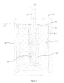
- FIG. 2 there is shown a cross-sectional view of a reaction chamber (40) in an embodiment of the present invention.
- This reaction chamber (40) is encased in a casing (44), which in a preferred embodiment is made from a metallic material.
- This reaction chamber (40) is provided on its top side with an intake port (43), said intake port (43) adapted to receive gaseous reactant (90) from the liquid gasification unit (50) for filling said gaseous reactant (90) into the reaction chamber (40).
- the intake port (43) is a pipe structure, or a plurality of pipe structures protruding into the reaction chamber (40). At an end of the pipe structure (43) that protrudes into the reaction chamber (40), there is provided a plurality of holes (49) that allow said gaseous reactant (90) to be expelled from the pipe structure (43) and into the reaction chamber (40).
- the plurality of holes (49) is surrounded by a first porous material (48).
- the pipe structure (43) and the first porous material (48) are disposed in concentric arrangement with respect to the reaction chamber (40), when looked at from a top side of the reaction chamber (40).
- the pipe structure (43) is located at the center of the concentric arrangement, and is enclosed concentrically by the first porous material (48).
- the first porous material is in turn enclosed concentrically by the solid reactant (47).
- the first porous material (48) is permeable to the gaseous reactant (90) but not to the solid reactant (47). In this way, the first porous material (48) allows the gaseous reactant (90) to pass into the solid reactant (47) but it does not allow the solid reactant (47) from escaping the reaction chamber (40).
- the gaseous reactant (90) when the gaseous reactant (90) is introduced into the reaction chamber (40) through the pipe structure (43), it diffuses out through the plurality of holes (49), through the first porous material (48), and is dispersed into the solid reactant (47), with which it reacts chemically. Hydrogen gas is produced by this chemical reaction.
- This hydrogen gas permeates through a second porous material (46) located at a top side of the solid reactant (47) and expelled from the reaction chamber (40) through the gas outlet (42).
- the solid reactant (47) is further encapsulated around its side by a third porous material (45).
- This third porous material (45) allows the hydrogen gas to permeate through, but it does not allow the solid reactant (47) to pass through. This prevents any melting of the solid reactant (47) from blocking the hydrogen gas passage to the top of the reaction chamber (40).
- the first, second and third porous materials are carbon cloth.
- a temperature sensing means (170) adapted to measure a temperature reading within the reaction chamber (40), this temperature reading then sent to the control unit (10).
- the control unit (10) is able to shut down the reaction in the reaction chamber (40) by closing the control valve (52) thereby stopping the supply of gaseous reactant (90) into the reaction chamber (40). This is a safety measure.
- reaction chamber (40) is a fixed part whereby the waste byproduct has to be cleaned out.
- reaction chamber (40) is mounted on the generator system using coupling means to facilitate easy removal and replacement of the entire reaction chamber (40), along with the waste byproduct inside it.
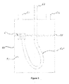
- FIG. 3 there is shown a cross-sectional view of a liquid storage (60) in an embodiment of the present invention.
- Liquid reactant (91) is filled into the liquid storage (60) through an intake port (61) from an external source.
- An exhaust port (63) channels the liquid reactant (91) out from the liquid storage (60).
- FIG 3 there is shown a flexible hose (65) with a first end connected to a floatation device (67), and a second end in fluid communication with the exhaust port (63).
- the floatation device (67) is adapted to float on a liquid storage level (66), and to keep the said first end of the flexible hose (65) underneath the surface level of said liquid reactant (91), as long as there is adequate liquid reactant (91) in the liquid storage (60).
- the flexible hose (65) is able to extract liquid reactant (91) from the liquid storage (60) regardless of the orientation of the liquid storage (60).
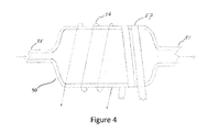
- the liquid gasification unit (50) is provided at a first end with an intake port (55) for receiving liquid reactant (91) from the liquid storage (60) via the liquid driving unit (64).
- the liquid gasification unit (50) is provided at a second end with an exhaust port (51) for expelling gaseous reactant (90) out of the liquid gasification unit (50).
- the intake port (55) has a narrower flow channel than the exhaust port (51). This narrower flow channel allows less of the liquid reactant (91) to enter the liquid gasification unit (50), thus allowing an easier conversion of the liquid reactant (91) into the gaseous reactant (90).
- the larger diameter of the exhaust port (51) also allows a higher throughput for the gaseous reactant (90) as it is expelled out from the liquid gasification unit (50).
- the liquid gasification unit (50) is provided with heating elements (56) for heating and gasifying the liquid reactant (91).
- the liquid gasification unit (50) is further provided with a heat conductive means (57) located on the exterior of the liquid gasification unit (50). This heat conductive means (57) channels excessive heat from the heat transfer device (53) to the liquid gasification unit (50).
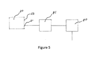
- FIG. 5 there is shown a diagrammatic view of a portion of a hydrogen generating system in an embodiment of the present invention with the addition of a gas regulator (81).
- This gas regulator (81) is located after the filter unit (80) and before the fuel cell (30) and in fluid communication with both the filter unit (80) and the fuel cell (30).
- This gas regulator (81) controls the pressure and flow rate of the hydrogen gas that passes through it.
- This gas regulator (81) is controlled by the control unit.
- Liquid driving unit controlling output (164)
Abstract
A hydrogen gas generating system that gasifies a liquid reactant such as water, then channeling the resultant gaseous reactant to a reaction chamber containing a solid hydride. The chemical reaction between the liquid reactant and solid hydride forming hydrogen gas. This hydrogen gas can be filtered and regulated before being used in a fuel cell to produce electricity. A control unit is used to control important parameters such as pressure and temperature of the various components, as well as initiate the hydrogen generating process when an energy storage device such as a battery goes below a preset level.
Description
The present invention relates generally to a
hydrogen gas generating system and method thereof, and
more particularly to such a system and method that
generates hydrogen gas from a chemical reaction between
a solid reactant and a gaseous reactant.
Fuel cells that produce electricity using
hydrogen gas as a fuel source are well known. Fuel cell
applications are for the most part mobile, and that
creates a problem to provide a constant supply of
hydrogen gas to power the fuel cell. A traditional
solution to this is to carry hydrogen gas in pressurized
tanks. These pressurized tanks are often heavy and
bulky, which is not suitable for applications where
weight is a concern, such as UAV and bicycle
applications. Another problem is pressurized hydrogen
gas tanks is the low energy storage density. Yet another
problem is the risk of leakage. Hydrogen gas is
odourless and burns without any flame, making it
especially hazardous in the case of a leak.
An alternative to carrying hydrogen gas around
in pressurized tanks is to generate hydrogen gas in
situ, and “on demand”. It is known that certain solid
hydrides or borohydrides, when mixed with liquids such
as water, can undergo a hydrolysis chemical reaction
that produces hydrogen gas. This eradicates all the
technical and hazardous drawbacks of carrying hydrogen
gas around in pressurized tanks. A typical example of
solid hydride hydrogen gas generation is using sodium
borohydride (NaBH4) as fuel. A common practice is mixing
sodium borohydride (NaBH4) with sodium hydroxide (NaOH)
to form an aqueous solution. When a noble metal catalyst
such as platinum or ruthenium is introduced, hydrolysis
of NaBH4 will take place and hydrogen gas is produced.
During the hydrolysis process, NaBH4 will be transformed
into sodium borate (NaBO2), which is insoluble in the
alkaline aqueous. NaBO2 precipitation also tends to
cloak up the catalyst surface area and render the
reaction terminated.
The use of liquid NaBH4 as a fuel also
presents other technical problems in a hydrogen
generating system. The presence of excess water gives
rise to unwanted weight, thus reducing the specific
storage density of the hydrogen generator. A liquid
mixture also poses a higher risk of an uncontrollable
runaway reaction, which may lead to catastrophic consequences.
Various means to limit the utilisation of
water in the system and to prevent the caking of the
hydrogen fuel inside the mixture have been attempted.
Kindler, et al (US 2008/0075987A1) discloses a means of
using steam for a better hydrolysis reaction on a metal
hydride fuel. US 2016/0049675A1 discloses another
hydrogen generator using sintered means to provide
liquid gasification and heat recollection for efficient
energy utilisation. Such inventions have demonstrated
better means to obtain hydrogen generation but at the
same time pose challenges on scaling the system for
higher performance.
It is therefore desirable to have a scalable
hydrogen generating system with a high efficiency and performance.
Accordingly, it is another objective of this
invention to provide a system to generate hydrogen on an
“on demand” basis.
It is another object of this invention to
provide a system to generate hydrogen that is lighter.
It is another object of this invention to
provide a system to generate hydrogen that is smaller.
The present invention seeks to overcome the
aforementioned disadvantages by providing a hydrogen gas
generating system that gasifies a liquid reactant such
as water, then channeling the resultant gaseous reactant
to a reaction chamber containing a solid hydride. The
chemical reaction between the gasified liquid reactant
and solid hydride forming hydrogen gas. This hydrogen
gas can be filtered and regulated before being used in a
fuel cell to produce electricity. A control unit is used
to control important parameters such as pressure and
temperature of the various components, as well as
initiate the hydrogen generating process when an energy
storage device such as a battery goes below a preset level.
This invention thus relates to a hydrogen
generating system, which includes a control unit having
an energy storage reading input, a pressure reading
input, a temperature reading input, a liquid driving
unit controlling output, a heating controlling output,
and a gaseous release controlling output. This hydrogen
generating system also includes a liquid storage having
an intake port for receiving a liquid reactant from an
external source, an exhaust port for expelling the
liquid reactant from the liquid storage, and an excess
intake port for receiving excess liquid recovered from a
condensation unit. This hydrogen generating system also
includes a liquid gasification unit having an exhaust
port, an intake port for receiving liquid reactant from
the liquid storage, heating elements controllable by the
control unit via the heating controlling output, the
liquid gasification unit adapted to heat an amount of
liquid reactant such that a portion of the liquid
reactant enters a gaseous phase. This hydrogen
generating system also includes a reaction chamber
having an intake port in fluid communication with the
liquid gasification unit exhaust port via a control
valve, the control valve controlled by the gaseous
release controlling output, the reaction chamber
containing a solid reactant, such as a metal hydride,
and adapted to receive an amount of gaseous reactant
from the liquid gasification unit, the gaseous reactant
dispersed into the solid reactant thereby forming a
chemical reaction that produces hydrogen gas. A product
gas being a mixture of any excess gaseous reactant and
the produced hydrogen gas is expelled from the reaction
chamber via a gas outlet. This hydrogen generating
system also includes a pressure sensing means for taking
a pressure reading at the reaction chamber intake port
and relaying the pressure reading to the control unit.
This hydrogen generating system also includes a
temperature sensing means for taking a temperature
reading inside the reaction chamber and relaying the
temperature reading to the control unit. This hydrogen
generating system also includes a condensation unit
having an intake port for receiving the product gas from
the reaction chamber, an exhaust port for channeling
primarily hydrogen gas out of the condensation unit, an
excess liquid port for channeling a condensate of the
gaseous reactant out of the condensation unit and back
into the liquid storage, the condensation unit adapted
to substantially condense the gaseous reactant.
In another aspect of this invention, this
hydrogen generating system further comprises a filter
unit adapted to filter said primarily hydrogen gas
thereby substantially removing unwanted particles from
said primarily hydrogen gas.
In another aspect of this invention, this
hydrogen generating system further comprises a liquid
driving unit provided between the said liquid storage
exhaust port and said liquid gasification unit intake
port, and adapted to propel liquid reactant from said
liquid storage and into said liquid gasification unit,
said liquid driving unit controllable by the said
control unit.
In another aspect of this invention, this
hydrogen generating system further comprises a control
valve adapted to allow release of said product gas from
said reaction chamber, said control valve controllable
by the said control unit.
In another aspect of this invention, the
liquid gasification unit is adapted to store an amount
of said gaseous reactant.
In another aspect of this invention, this
hydrogen generating system further comprises a heat
transfer means adapted to transfer heat from said
reaction chamber to said liquid gasification unit.
In another aspect of this invention, this
hydrogen generating system further comprises an energy
storage, such as a battery, said energy storage adapted
to store an amount of electrical energy it receives. A
storage level of this energy storage is relayed to the
control unit.
In another aspect of this invention, the
control unit initiates a hydrogen gas generating process
when the said storage level of the energy storage is
reduced to a preset level.
In another aspect of this invention, this
hydrogen generating system further comprises a fuel cell
having an intake port for receiving an amount of the
primarily hydrogen gas for conversion to electrical energy.
In another aspect of this invention, a portion
of the electrical energy produced by the fuel cell is
used to power an external electrical load and another
portion of the electrical energy produced is used to
charge the energy storage.
In another aspect of this invention, this
hydrogen generating system further comprises a means of
ensuring that the liquid reactant flows out of the
liquid storage so long as there is adequate liquid
reactant in the liquid storage. This means of ensuring
that the liquid reactant flows out of the liquid storage
comprises a flexible hose with a first end connected to
a floatation device, and a second end in fluid
communication with the liquid storage exhaust port, and
such that the floatation device is adapted to keep the
first end of the flexible hose underneath the surface of
the liquid reactant, as long as there is adequate liquid
reactant in the liquid storage. In this way, the
flexible hose is able to extract liquid reactant from
the liquid storage regardless of the orientation of the
liquid storage.
In another aspect of this invention, the
liquid reactant includes any of: water, acidic liquid,
alkaline liquid, organic or inorganic liquids or a
combination thereof.
In another aspect of this invention, the solid
reactant comprises of a mixture of hydrogen fuel and a
metal based catalyst.
In another aspect of this invention, the
hydrogen fuel is sodium borohydride.
In another aspect of this invention, the
hydrogen fuel is any of: boron hydride, nitrogen
hydride, carbon hydride, metal hydride, boron nitrogen
hydride, boron carbon hydride, nitrogen carbon hydride,
metal boron hydride, metal nitrogen hydride, metal
carbon hydride, metal boron nitrogen hydride, metal
boron carbon hydride, metal carbon nitrogen hydride,
boron nitrogen carbon hydride, metal boron nitrogen
carbon hydride, or the combination thereof.
In another aspect of this invention, the
hydrogen fuel is any of: NaH, LiBH4, LiH, CaH2,
Ca(BH4)2, MgBH4, KBH4, Al(BH3)3, or the combination thereof.
In another aspect of this invention, the solid
reactant may be various compounds having BxNyHz, where
x, y and z are any integer numbers. Tthe various
compounds may include: H3BNH3, H2B(NH3)2BH3, NH2BH2,
B3N3H6, morpholineborane (C4H12BNO), (CH2)4O composite
material, B2H4, or a combination thereof.
In another aspect of this invention, the metal
based catalyst is any of: a cobalt based oxide, a
boride, a solid acid, a salt, or a combination thereof.
The salt can be a compound of the ions of any of:
ruthenium (Ru), cobalt (Co), nickel (Ni), copper (Cu),
iron (Fe) or a combination thereof.
In another aspect of this invention, the
hydrogen generating system further comprises a gas
regulating means located after a filter and before a
fuel cell, the gas regulating means adapted to regulate
a pressure and flow rate of a gas passing through it.
In another aspect of this invention, the
reaction chamber is easily removable from the system and
provided with means of temporarily closing the intake
port and gas outlet during its removal. This facilitates
easy changing of a reaction chamber when the solid
reactant inside is used up.
Another aspect of this invention is a method
of generating hydrogen gas, comprising the following steps:
a. detect a storage level of an energy storage;
b. if said storage level has reduced to a
predetermined level, activate a liquid driving unit (64)
that propels a liquid reactant from a liquid storage
into a liquid gasification unit;
c. activate heating elements in said liquid
gasification unit such that at least a portion of the
said liquid reactant is gasified;
d. allow the said gaseous reactant to
disperse inside a reaction chamber containing an amount
of solid reactant, the contact between the said gaseous
reactant and solid reactant producing hydrogen gas;
e. condense any gaseous reactant mixed with
said hydrogen gas to separate it from the said hydrogen gas;
f. return said condensed gaseous reactant
to said liquid storage;
g. filter said hydrogen gas to
substantially remove unwanted particles;
h. transferring an amount of heat generated
in the said reaction chamber to the said liquid
gasification unit;
i regulating a pressure and flow rate of
the said hydrogen gas.
Other objects and advantages will be more
fully apparent from the following disclosure and
appended claims.
Lack of Hydrogen gas generating systems
that produce Hydrogen gas “on demand” that is
scalable, has high performance, and is easy to maintain.
A hydrogen gas generating system that
gasifies a liquid reactant such as water, then
channeling the resultant gaseous reactant to a
reaction chamber containing a solid hydride. The
chemical reaction between the liquid reactant and
solid hydride forming hydrogen gas. This hydrogen
gas can be filtered and regulated before being used
in a fuel cell to produce electricity. A control
unit is used to control important parameters such as
pressure and temperature of the various components,
as well as initiate the hydrogen generating process
when an energy storage device such as a battery goes
below a preset level.
The hydrogen gas generating system of this
invention also recovers extra heat from the reaction
to assist in gasifying the liquid reactant.
It should be noted that the following detailed
description is directed to a hydrogen generating system
and method thereof, and is not limited to any particular
size or configuration but in fact a multitude of sizes
and configurations within the general scope of the
following description.
Referring to Figure 1, there is shown a
hydrogen generating system. The overall purpose of this
system is to generate hydrogen gas for electricity
production in a fuel cell in situ, thus
eliminating the need for storing large amounts of
pressurized hydrogen gas. There is shown an energy
storage (13), which in preferred embodiments can be a
battery or capacitor. When a sensor detects a drop of
energy level in the energy storage (13) below a preset
level, a control unit (10) initiates a hydrogen gas
generating process. In a preferred embodiment, the
control unit (10) includes a microcontroller.
This hydrogen gas generating process includes
the control unit (10), via heating controlling output
(15), switching on heating elements (56) of a liquid
gasification unit (50). This causes an internal
temperature of the liquid gasification unit (50) to
increase. When the internal temperature of the liquid
gasification unit (50) reaches a preset value, the
control unit (10) will, via liquid driving unit
controlling output (164), activate a liquid driving unit
(64). This liquid driving unit (64) is adapted to pump
liquid reactant (91) that is stored in a liquid storage
(60), out via a liquid storage exhaust port (63),
through a liquid flow guide (635), and into the liquid
gasification unit (50) via a liquid gasification unit
intake port (55). As the liquid reactant (91) enters the
liquid gasification unit (50), it rapidly heats up until
it undergoes a change into a gaseous phase, thus
becoming a gaseous reactant (90). This gaseous reactant
(90) is stored and pressurized in the liquid
gasification unit (50).
Still referring to the hydrogen gas generating
process, the control unit (10), via a gaseous release
controlling output (152), activates a control valve
(52). This control valve (52) when activated releases
the stored gaseous reactant (90) out from the liquid
gasification unit (50) via a liquid gasification unit
exhaust port (51). The gaseous reactant (90) then passes
through the control valve (52) and enters a reaction
chamber (40) via a reaction chamber intake port (43).
Upon entering the reaction chamber (40), the gaseous
reactant reacts chemically with a solid reactant (47)
that is stored in the reaction chamber (40). A pressure
of the reaction chamber (40) is measured by a pressure
sensing means (14). This pressure reading is fed back to
the control unit (10). A temperature of the reaction
chamber (40) is also measured by a temperature sensing
means (170), and this temperature reading is also fed
back to the control unit (10). When these pressure and
temperature readings reach a preset value, the control
unit (10) is able to shut down the reaction in the
reaction chamber (40) by closing the control valve (52)
thereby stopping the supply of gaseous reactant (90)
into the reaction chamber (40). This is a safety measure.
The reaction between the gaseous reactant and
the solid reactant (47) in the reaction chamber (40)
produces hydrogen gas, among other by-products.
This reaction is an exothermic reaction, and
thus increases the temperature of the reaction chamber
(40). This excess heat energy is transferred back to the
liquid gasification unit (50) via a heat transfer device
(53) located in between the reaction chamber (40) and
the liquid gasification unit (50). This heat transfer
device (53) conductively transfers the excess heat
produced in the reaction chamber (40) to the liquid
gasification unit (50) by means of a heat conductor
(54). This reduces the power requirement of the heating
element (56) in the liquid gasification unit (50) and
further enhances the output performance of this hydrogen
gas generating system.
Primarily hydrogen gas and some other
by-products is produced by the reaction between the said
gaseous reactant and solid reactant (47) in the reaction
chamber (40). A product gas, which is a mixture of this
primarily hydrogen gas and any excess said gaseous
reactant (90) which did not react with the solid
reactant (47), is channeled out from the reaction
chamber (40) through a gas outlet (42) and via a gas
flow guide (41) into a condensation unit (70).
To further clarify the workings of the
reaction chamber (40):
A gas that has been gasified in the liquid
gasification unit (50), which we call gaseous reactant
(90), enters the reaction chamber (40).
This gaseous reactant (90) reacts with a solid
reactant (47) provided in the reaction chamber (40);
this reaction producing primarily hydrogen gas and some by-products.
A product gas, which is a mixture of said
primarily hydrogen gas and any excess gaseous reactant
(90), is expelled from the reaction chamber.
This condensation unit (70) is provided with
an intake port (71) for receiving the said product gas
from the reaction chamber (40). The primary function of
this condensation unit (70), is to condense the said
gaseous reactant (90) back into a liquid, so that it
separates from the primarily hydrogen gas. The resulting
condense liquid is then channeled out through an excess
liquid port (73) to return to the liquid storage via a
liquid storage return port (62). The primarily hydrogen
gas is expelled from the condensation unit (70) via an
exhaust port (72) into a filter unit (80). The filter
unit (80) traps unwanted particles in the primarily
hydrogen gas, to make it purer. After the filter unit
(80), the hydrogen gas is channeled into a fuel cell
unit (30) through an intake port (31), which in a
preferred embodiment, is a valve. The hydrogen gas
undergoes an electrochemical conversion in the fuel cell
(30) to produce electrical energy. An exhaust gas
produced by the fuel cell (30) is channeled out through
an exhaust means (33), which in a preferred embodiment,
is a valve. The fuel cell (30) can be any device which
converts hydrogen gas into usable electric energy, and
can be any of, but not limited to, the following: a
proton exchange membrane fuel cell (PEMFC), alkaline
fuel cell (AFC), phosphoric acid fuel cell (PAFC),
molten carbonate fuel cell (MCFC), solid oxide fuel cell
(SOFC), or other sorts of fuel cells.
In this preferred embodiment, electrical
energy produced by the fuel cell (30) is channeled
through an electric power converter (20), which can be
any of, but not limited to: DC converter, inverter, or
charge controller. The electric power converter (20)
then outputs a portion of the said electrical energy to
an electric load (21) through load interconnect (22). At
the same time, another portion of the said electrical
energy is sent back to the energy storage (13) via a
recharge interconnect (12). This charges the energy
storage (13) when needed. Yet another portion of the
said electrical energy is used to power the control unit (10).
In other embodiments, the hydrogen generating
system of the present invention can be used without the
fuel cell, in any application where a supply of hydrogen
gas is needed.
Still referring to Figure 1, it can be seen
that the liquid storage (60) is provided with a liquid
storage intake port (61) through which liquid reactant
(91) can be added. In a preferred embodiment, the liquid
reactant (91) is water. However, the liquid reactant
(91) can also be a diluted concoction of methyl alcohol,
ethyl alcohol, and any other organic or inorganic
solvent, such as ethylene glycol.
The solid reactant stored in the reaction
chamber (40) comprises of a powder mixture of hydrogen
fuel with a metal based catalyst. In a preferred
embodiment, the hydrogen fuel is sodium borohydride.
However, in other embodiments, this hydrogen fuel can
also be other types of solid hydrides, such as boron
hydride, nitrogen hydride, carbon hydride, metal
hydride, boron nitrogen hydride, boron carbon hydride,
nitrogen carbon hydride, metal boron hydride, metal
nitrogen hydride, metal carbon hydride, metal boron
nitrogen hydride, metal boron carbon hydride, metal
carbon nitrogen hydride, boron nitrogen carbon hydride,
metal boron nitrogen carbon hydride, or combinations
thereof. This hydrogen fuel can also include: NaH,
LiBH4, LiH, CaH2, Ca(BH4)2, MgBH4, KBH4 and Al(BH3)3, or
combinations thereof. In addition, the solid reactant
may be various compounds having BxNyHz and include, but
not limited thereto, H3BNH3, H2B(NH3)2BH3, NH2BH2,
B3N3H6, morpholineborane (C4H12BNO), (CH2)4O composite
material, B2H4, or combinations thereof. In preferred
embodiments, the metal based catalyst is made of cobalt
based oxide or boride, or may be solid acid or salt
including ruthenium (Ru), cobalt (Co), nickel (Ni),
copper (Cu), iron (Fe) or compound manufactured by the
ions thereof.
Referring to Figure 2, there is shown a
cross-sectional view of a reaction chamber (40) in an
embodiment of the present invention. This reaction
chamber (40) is encased in a casing (44), which in a
preferred embodiment is made from a metallic material.
This reaction chamber (40) is provided on its top side
with an intake port (43), said intake port (43) adapted
to receive gaseous reactant (90) from the liquid
gasification unit (50) for filling said gaseous reactant
(90) into the reaction chamber (40).
In preferred embodiments, the intake port (43)
is a pipe structure, or a plurality of pipe structures
protruding into the reaction chamber (40). At an end of
the pipe structure (43) that protrudes into the reaction
chamber (40), there is provided a plurality of holes
(49) that allow said gaseous reactant (90) to be
expelled from the pipe structure (43) and into the
reaction chamber (40). The plurality of holes (49) is
surrounded by a first porous material (48).
In a preferred embodiment, the pipe structure
(43) and the first porous material (48) are disposed in
concentric arrangement with respect to the reaction
chamber (40), when looked at from a top side of the
reaction chamber (40). The pipe structure (43) is
located at the center of the concentric arrangement, and
is enclosed concentrically by the first porous material
(48). The first porous material is in turn enclosed
concentrically by the solid reactant (47). The first
porous material (48) is permeable to the gaseous
reactant (90) but not to the solid reactant (47). In
this way, the first porous material (48) allows the
gaseous reactant (90) to pass into the solid reactant
(47) but it does not allow the solid reactant (47) from
escaping the reaction chamber (40).
Thus, when the gaseous reactant (90) is
introduced into the reaction chamber (40) through the
pipe structure (43), it diffuses out through the
plurality of holes (49), through the first porous
material (48), and is dispersed into the solid reactant
(47), with which it reacts chemically. Hydrogen gas is
produced by this chemical reaction. This hydrogen gas
permeates through a second porous material (46) located
at a top side of the solid reactant (47) and expelled
from the reaction chamber (40) through the gas outlet
(42). The solid reactant (47) is further encapsulated
around its side by a third porous material (45). This
third porous material (45) allows the hydrogen gas to
permeate through, but it does not allow the solid
reactant (47) to pass through. This prevents any melting
of the solid reactant (47) from blocking the hydrogen
gas passage to the top of the reaction chamber (40). In
a preferred embodiment, the first, second and third
porous materials are carbon cloth.
Still referring to Figure 2, there is shown a
temperature sensing means (170) adapted to measure a
temperature reading within the reaction chamber (40),
this temperature reading then sent to the control unit
(10). When this temperature reading reaches a preset
value, the control unit (10) is able to shut down the
reaction in the reaction chamber (40) by closing the
control valve (52) thereby stopping the supply of
gaseous reactant (90) into the reaction chamber (40).
This is a safety measure.
In one preferred embodiment, the reaction
chamber (40) is a fixed part whereby the waste byproduct
has to be cleaned out. In another preferred embodiment,
the reaction chamber (40) is mounted on the generator
system using coupling means to facilitate easy removal
and replacement of the entire reaction chamber (40),
along with the waste byproduct inside it.
Referring now to Figure 3, there is shown a
cross-sectional view of a liquid storage (60) in an
embodiment of the present invention. Liquid reactant
(91) is filled into the liquid storage (60) through an
intake port (61) from an external source. An exhaust
port (63) channels the liquid reactant (91) out from the
liquid storage (60).
In Figure 3, there is shown a flexible hose
(65) with a first end connected to a floatation device
(67), and a second end in fluid communication with the
exhaust port (63). The floatation device (67) is adapted
to float on a liquid storage level (66), and to keep the
said first end of the flexible hose (65) underneath the
surface level of said liquid reactant (91), as long as
there is adequate liquid reactant (91) in the liquid
storage (60). In this way, the flexible hose (65) is
able to extract liquid reactant (91) from the liquid
storage (60) regardless of the orientation of the liquid
storage (60).
Still referring to Figure 3, there is provided
a return port (62) on the liquid storage (60) for
receiving excess liquid from the condensation unit (70).
Referring to Figure 4, there is shown an
external and cross-sectional view of a liquid
gasification unit (50) in an embodiment of the present
invention. The liquid gasification unit (50) is provided
at a first end with an intake port (55) for receiving
liquid reactant (91) from the liquid storage (60) via
the liquid driving unit (64). The liquid gasification
unit (50) is provided at a second end with an exhaust
port (51) for expelling gaseous reactant (90) out of the
liquid gasification unit (50). The intake port (55) has
a narrower flow channel than the exhaust port (51). This
narrower flow channel allows less of the liquid reactant
(91) to enter the liquid gasification unit (50), thus
allowing an easier conversion of the liquid reactant
(91) into the gaseous reactant (90). The larger diameter
of the exhaust port (51) also allows a higher throughput
for the gaseous reactant (90) as it is expelled out from
the liquid gasification unit (50). The liquid
gasification unit (50) is provided with heating elements
(56) for heating and gasifying the liquid reactant (91).
The liquid gasification unit (50) is further
provided with a heat conductive means (57) located on
the exterior of the liquid gasification unit (50). This
heat conductive means (57) channels excessive heat from
the heat transfer device (53) to the liquid gasification
unit (50).
Referring now to Figure 5, there is shown a
diagrammatic view of a portion of a hydrogen generating
system in an embodiment of the present invention with
the addition of a gas regulator (81). This gas regulator
(81) is located after the filter unit (80) and before
the fuel cell (30) and in fluid communication with both
the filter unit (80) and the fuel cell (30). This gas
regulator (81) controls the pressure and flow rate of
the hydrogen gas that passes through it. There can be
embodiments with just one gas regulator or a cluster of
gas regulators. In a preferred embodiment, this gas
regulator (81) is controlled by the control unit.
While several particularly preferred
embodiments of the present invention have been described
and illustrated, it should now be apparent to those
skilled in the art that various changes and
modifications can be made without departing from the
spirit and scope of the invention. Accordingly, the
following claims are intended to embrace such changes,
modifications, and areas of application that are within
the scope of this invention.
Control unit (10)
Recharge interconnect (12)
Energy storage (13)
Pressure sensing means (14)
Heating controlling output (15)
Electric power converter (20)
Electric load (21)
Load interconnect (22)
Fuel cell (30)
Fuel cell intake port (31)
Fuel cell exhaust (33)
Reaction chamber (40)
Gas flow guide (41)
Reaction chamber gas outlet (42)
Reaction chamber intake port / pipe structure
(43)
Reaction chamber casing (44)
Third porous material (45)
Second porous material (46)
Solid reactant (47)
First porous material (48)
Plurality of holes (49)
Liquid gasification unit (50)
Liquid gasification unit exhaust port (51)
Control valve (52)
Heat transfer device (53)
Heat conductor (54)
Liquid gasification unit intake port (55)
Heating element (56)
Heat conductive means (57)
Liquid storage (60)
Liquid storage intake port (61)
Liquid storage return port (62)
Liquid storage exhaust port (63)
Liquid flow guide (635)
Liquid driving unit (64)
Flexible hose (65)
Liquid storage level (66)
Floatation device (67)
Condensation unit (70)
Condensation unit intake port (71)
Condensation unit exhaust port (72)
Condensation unit excess liquid port (73)
Filter unit (80)
Gas regulator (81)
Gaseous reactant (90)
Liquid reactant (91)
Gaseous release controlling output (152)
Liquid driving unit controlling output (164)
Temperature sensing means (170)
Claims (31)
- A hydrogen generating system, comprising:
a control unit (10);
a liquid storage (60) having an intake port (61) for receiving liquid reactant (91) from an external source, an exhaust port (63) for expelling liquid reactant (91) from said liquid storage (60);
a liquid gasification unit (50) having an exhaust port (51), an intake port (55) for receiving liquid reactant (91) from said liquid storage (60), heating elements (56) controllable by said control unit (10), said liquid gasification unit (50) adapted to heat an amount of liquid reactant (91) such that a portion of said liquid reactant (91) enters a gaseous phase;
a reaction chamber (40) having an intake port (43) in fluid communication with said liquid gasification unit exhaust port (51) via a control valve (52), said control valve (52) controlled by said control unit (10), said reaction chamber (40) containing a solid reactant (47) and adapted to receive an amount of gaseous reactant (90) from the said liquid gasification unit (50), which said gaseous reactant (90) is dispersed through said solid reactant (47) thereby producing at least a product gas, said product gas being at least a mixture of said gaseous reactant (90) and hydrogen gas, and said product gas expelled from the reaction chamber (40) via a gas outlet (42); and
a condensation unit (70) having an intake port (71) for receiving said product gas from said reaction chamber (40), an exhaust port (72) for channeling primarily hydrogen gas out of said condensation unit (70), said condensation unit (70) adapted to substantially condense said gaseous reactant (90). - A hydrogen generating system according to claim 1, further comprising a filter unit (80) adapted to filter said primarily hydrogen gas thereby substantially removing unwanted particles from said primarily hydrogen gas.
- A hydrogen generating system according to claim 1, further comprising a liquid driving unit (64) provided between the said liquid storage exhaust port (63) and said liquid gasification unit intake port (55), and adapted to propel liquid reactant (91) from said liquid storage (60) and into said liquid gasification unit (50), said liquid driving unit (64) controllable by the said control unit (10).
- A hydrogen generating system according to claim 1, further comprising a control valve (52) adapted to allow release of said gaseous reactant (90) from said liquid gasification unit (50), said control valve (52) controllable by the said control unit (10).
- A hydrogen generating system according to claim 1, wherein said liquid gasification unit (50) is adapted to store an amount of said gaseous reactant (90).
- A hydrogen generating system according to claim 1, further comprising a heat transfer means (53) adapted to transfer heat from said reaction chamber (40) to said liquid gasification unit (50).
- A hydrogen generating system according to claim 1, further comprising an energy storage (13), said energy storage adapted to store an amount of electrical energy it receives, a storage level of said energy storage (13) relayed to said control unit (10).
- A hydrogen generating system according to claim 7, wherein the control unit (10) initiates a hydrogen gas generating process when the said storage level of said energy storage (13) is reduced to a preset level.
- A hydrogen generating system according to claim 1, further comprising a fuel cell (30) having an intake port (31) for receiving an amount of said primarily hydrogen gas for conversion to electrical energy.
- A hydrogen generating system according to claim 9, wherein a portion of the said electrical energy is used to power an external electrical load and a portion of the said electrical energy is used to charge the said energy storage (13).
- A hydrogen generating system according to claim 1, further comprising a means of ensuring that the liquid reactant (91) flows out of the liquid storage (60) so long as there is adequate liquid reactant (91) in said liquid storage (60).
- A hydrogen generating system according to claim 11, wherein said means of ensuring that the liquid reactant (91) flows out of the liquid storage (60) comprises a flexible hose (65) with a first end connected to a floatation device (67), and a second end in fluid communication with said liquid storage exhaust port (63), and such that said floatation device (67) is adapted to keep said first end of flexible hose (65) underneath the surface of said liquid reactant (91) as long as there is adequate liquid reactant (91) in the liquid storage (60).
- A hydrogen generating system according to claim 1, wherein the said liquid reactant (91) includes any of: water, acidic liquid, alkaline liquid, organic or inorganic liquids or a combination thereof.
- A hydrogen generating system according to claim 1, wherein the said solid reactant (47) comprises of a mixture of hydrogen fuel and a metal based catalyst.
- A hydrogen generating system according to claim 14, wherein the said hydrogen fuel is sodium borohydride.
- A hydrogen generating system according to claim 14, wherein the said hydrogen fuel is any of: boron hydride, nitrogen hydride, carbon hydride, metal hydride, boron nitrogen hydride, boron carbon hydride, nitrogen carbon hydride, metal boron hydride, metal nitrogen hydride, metal carbon hydride, metal boron nitrogen hydride, metal boron carbon hydride, metal carbon nitrogen hydride, boron nitrogen carbon hydride, metal boron nitrogen carbon hydride, or the combination thereof.
- A hydrogen generating system according to claim 14, wherein the said hydrogen fuel is any of: NaH, LiBH4, LiH, CaH2, Ca(BH4)2, MgBH4, KBH4, Al(BH3)3, or the combination thereof.
- A hydrogen generating system according to claim 14, wherein the said solid reactant may be various compounds having BxNyHz, where x, y and z are any integer numbers.
- A hydrogen generating system according to claim 18, wherein the said various compounds include: H3BNH3, H2B(NH3)2BH3, NH2BH2, B3N3H6, morpholineborane (C4H12BNO), (CH2)4O composite material, B2H4, or a combination thereof.
- A hydrogen generating system according to claim 14, wherein the said metal based catalyst is any of: a cobalt based oxide, a boride, a solid acid, a salt, or a combination thereof.
- A hydrogen generating system according to claim 20, wherein the said salt is a compound of the ions of any of: ruthenium (Ru), cobalt (Co), nickel (Ni), copper (Cu), iron (Fe) or a combination thereof.
- A hydrogen generating system according to claim 1, further comprising a gas regulating means (81) located after a filter (80) and before a fuel cell (30), the gas regulating means (81) adapted to regulate a pressure and flow rate of a gas passing through it.
- A hydrogen generating system according to claim 1, wherein the reaction chamber (40) is easily removable from the system and provided with means of temporarily closing the intake port (43) and gas outlet (42) during its removal.
- A hydrogen generating system according to claim 1, wherein the said heating elements (56) can be operated electrically by resistive heating or inductive heating.
- A hydrogen generating system according to claim 1, wherein the said condensation unit (70) further comprises an excess liquid port (73) for channeling a condensate of said gaseous reactant (90) out of said condensation unit (70) and back into said liquid storage (60).
- A hydrogen generating system according to claim 1, further comprising a pressure sensing means (14) for taking a pressure reading at the reaction chamber intake port (43) and relaying the pressure reading to the control unit (10).
- A hydrogen generating system according to claim 1, further comprising a temperature sensing means (170) for taking a temperature reading inside the reaction chamber (40) and relaying the temperature reading to the control unit (10).
- A method of generating hydrogen gas, comprising the following steps:
- detect a storage level of an energy storage (13);if said storage level has reduced to a predetermined level, activate a liquid driving unit (64) that propels a liquid reactant (91) from a liquid storage (60) into a liquid gasification unit (50);activate heating elements (56) in said liquid gasification unit (50) such that at least a portion of the said liquid reactant (91) is gasified;allow the said gaseous reactant (90) to disperse inside a reaction chamber (40) containing an amount of solid reactant (47), the contact between the said gaseous reactant (90) and solid reactant (47) producing hydrogen gas;condense any gaseous reactant (90) mixed with said hydrogen gas to separate it from the said hydrogen gas;return said condensed gaseous reactant (90) to said liquid storage (60); andfilter said hydrogen gas to substantially remove unwanted materials.
- A method of generating hydrogen gas according to claim 28, further comprising the following step:transferring an amount of heat generated in the said reaction chamber (40) to the said liquid gasification unit (50).
- A method of generating hydrogen gas according to claim 28, further comprising the following step:regulating a pressure and flow rate of the said hydrogen gas.
Priority Applications (15)
| Application Number | Priority Date | Filing Date | Title |
|---|---|---|---|
| PCT/MY2017/050007 WO2018143790A1 (en) | 2017-02-03 | 2017-02-03 | Hydrogen gas generating system and method thereof |
| EP17894778.4A EP3577063A4 (en) | 2017-02-03 | 2017-06-28 | Hydrogen gas generating system and method with buffer tank |
| CN201780054874.7A CN109982963B (en) | 2017-02-03 | 2017-06-28 | Hydrogen generation system and method with buffer tank |
| PCT/MY2017/050033 WO2018143791A1 (en) | 2017-02-03 | 2017-06-28 | Hydrogen gas generating system and method with buffer tank |
| BR112019016094-9A BR112019016094B1 (en) | 2017-02-03 | 2017-06-28 | HYDROGEN GAS GENERATOR SYSTEM AND BUFFER TANK METHOD |
| MX2019008954A MX2019008954A (en) | 2017-02-03 | 2017-06-28 | Hydrogen gas generating system and method with buffer tank. |
| AU2017397577A AU2017397577A1 (en) | 2017-02-03 | 2017-06-28 | Hydrogen gas generating system and method with buffer tank |
| RU2019126861A RU2019126861A (en) | 2017-02-03 | 2017-06-28 | METHOD FOR GENERATING GASEOUS HYDROGEN AND SYSTEM FOR ITS IMPLEMENTATION WITH BUFFER CAPACITY |
| JP2019563999A JP2020506871A (en) | 2017-02-03 | 2017-06-28 | Hydrogen gas generation system and method with buffer tank |
| KR1020197024820A KR20190105241A (en) | 2017-02-03 | 2017-06-28 | Hydrogen gas generation system and method using buffer tank |
| US16/482,693 US20200002164A1 (en) | 2017-02-03 | 2017-06-28 | Hydrogen gas generating system and method with buffer tank |
| SG11201907072WA SG11201907072WA (en) | 2017-02-03 | 2017-06-28 | Hydrogen gas generating system and method with buffer tank |
| CA3052575A CA3052575A1 (en) | 2017-02-03 | 2017-06-28 | Hydrogen gas generating system and method with buffer tank |
| TW107100559A TW201840465A (en) | 2017-02-03 | 2018-01-05 | Hydrogen gas generating system and method thereof |
| ZA2019/05622A ZA201905622B (en) | 2017-02-03 | 2019-08-26 | Hydrogen gas generating system and method with buffer tank |
Applications Claiming Priority (1)
| Application Number | Priority Date | Filing Date | Title |
|---|---|---|---|
| PCT/MY2017/050007 WO2018143790A1 (en) | 2017-02-03 | 2017-02-03 | Hydrogen gas generating system and method thereof |
Related Child Applications (1)
| Application Number | Title | Priority Date | Filing Date |
|---|---|---|---|
| US16/482,693 Continuation-In-Part US20200002164A1 (en) | 2017-02-03 | 2017-06-28 | Hydrogen gas generating system and method with buffer tank |
Publications (1)
| Publication Number | Publication Date |
|---|---|
| WO2018143790A1 true WO2018143790A1 (en) | 2018-08-09 |
Family
ID=63039894
Family Applications (2)
| Application Number | Title | Priority Date | Filing Date |
|---|---|---|---|
| PCT/MY2017/050007 WO2018143790A1 (en) | 2017-02-03 | 2017-02-03 | Hydrogen gas generating system and method thereof |
| PCT/MY2017/050033 WO2018143791A1 (en) | 2017-02-03 | 2017-06-28 | Hydrogen gas generating system and method with buffer tank |
Family Applications After (1)
| Application Number | Title | Priority Date | Filing Date |
|---|---|---|---|
| PCT/MY2017/050033 WO2018143791A1 (en) | 2017-02-03 | 2017-06-28 | Hydrogen gas generating system and method with buffer tank |
Country Status (13)
| Country | Link |
|---|---|
| US (1) | US20200002164A1 (en) |
| EP (1) | EP3577063A4 (en) |
| JP (1) | JP2020506871A (en) |
| KR (1) | KR20190105241A (en) |
| CN (1) | CN109982963B (en) |
| AU (1) | AU2017397577A1 (en) |
| CA (1) | CA3052575A1 (en) |
| MX (1) | MX2019008954A (en) |
| RU (1) | RU2019126861A (en) |
| SG (1) | SG11201907072WA (en) |
| TW (1) | TW201840465A (en) |
| WO (2) | WO2018143790A1 (en) |
| ZA (1) | ZA201905622B (en) |
Cited By (3)
| Publication number | Priority date | Publication date | Assignee | Title |
|---|---|---|---|---|
| WO2018143791A1 (en) | 2017-02-03 | 2018-08-09 | Galaxy Fct Sdn. Bhd. | Hydrogen gas generating system and method with buffer tank |
| WO2020124227A1 (en) * | 2018-12-21 | 2020-06-25 | Hydrogen In Motion Inc. (H2M) | Method for generating hydrogen from a nitrogen containing borane compound and active metal borohydride mixture |
| CN111439724A (en) * | 2020-05-12 | 2020-07-24 | 河南中氢动力研究院有限公司 | Hydrogen production system, apparatus and method |
Families Citing this family (6)
| Publication number | Priority date | Publication date | Assignee | Title |
|---|---|---|---|---|
| KR102347152B1 (en) * | 2020-04-13 | 2022-01-04 | 국방과학연구소 | System of polymer electrolyte membrane fuel cell comprising hydrogen generator |
| CN111509269B (en) * | 2020-04-24 | 2021-09-14 | 艾氢技术(苏州)有限公司 | But continuous hydrogen power generation device |
| CN111675193A (en) * | 2020-07-22 | 2020-09-18 | 河南中氢动力研究院有限公司 | Portable automatic voltage stabilization hydrogen production equipment |
| CN112250038B (en) * | 2020-09-16 | 2023-08-25 | 艾氢技术(苏州)有限公司 | Hydrogen generating device for constant-temperature reaction of solid hydrogen |
| CN112290067B (en) * | 2020-09-21 | 2023-11-17 | 艾氢技术(苏州)有限公司 | Fruit acid catalytic hydration hydrogen generation device based on solid hydrogen |
| CN114634157A (en) * | 2022-03-28 | 2022-06-17 | 西安交通大学 | System for controlling hydrolysis hydrogen production speed and control method thereof |
Citations (5)
| Publication number | Priority date | Publication date | Assignee | Title |
|---|---|---|---|---|
| JP2007335144A (en) * | 2006-06-13 | 2007-12-27 | Matsushita Electric Ind Co Ltd | Non-stationary fuel cell system |
| JP2010235359A (en) * | 2009-03-30 | 2010-10-21 | Hitachi Ltd | Hydrogen supply method and hydrogen supply apparatus |
| JP2012036023A (en) * | 2010-08-04 | 2012-02-23 | Hitachi Maxell Energy Ltd | Liquid storing vessel, hydrogen production apparatus and fuel cell system |
| JP2015227257A (en) * | 2014-05-30 | 2015-12-17 | Jx日鉱日石エネルギー株式会社 | Hydrogen supply system |
| JP2016041647A (en) * | 2014-08-15 | 2016-03-31 | 中強光電股▲ふん▼有限公司 | Hydrogen generator and power generation equipment |
Family Cites Families (17)
| Publication number | Priority date | Publication date | Assignee | Title |
|---|---|---|---|---|
| US7938077B1 (en) * | 1993-05-27 | 2011-05-10 | The United States Of America As Represented By The Secretary Of The Navy | Hydrogen generation apparatus for an underwater vehicle |
| US5593640A (en) * | 1995-06-07 | 1997-01-14 | Ball Corporation | Portable hydrogen generator |
| US6737184B2 (en) * | 2001-11-09 | 2004-05-18 | Hydrogenics Corporation | Chemical hydride hydrogen generation system and an energy system incorporating the same |
| WO2006081402A2 (en) * | 2005-01-28 | 2006-08-03 | Millennium Cell, Inc. | Systems and methods for controlling hydrogen generation |
| US7666386B2 (en) * | 2005-02-08 | 2010-02-23 | Lynntech Power Systems, Ltd. | Solid chemical hydride dispenser for generating hydrogen gas |
| US7951349B2 (en) * | 2006-05-08 | 2011-05-31 | The California Institute Of Technology | Method and system for storing and generating hydrogen |
| WO2008014460A2 (en) * | 2006-07-27 | 2008-01-31 | Trulite, Inc. | Apparatus, system, and method for generating hydrogen from a chemical hydride |
| EP2168188A4 (en) * | 2007-05-18 | 2012-04-04 | Enerfuel Inc | Hydrogen production from borohydrides and glycerol |
| WO2008151367A1 (en) * | 2007-06-12 | 2008-12-18 | Alternative Energy International Ltd | A system for production of hydrogen |
| JP5186824B2 (en) * | 2007-07-18 | 2013-04-24 | 株式会社豊田中央研究所 | Hydrogen generator |
| TWI371427B (en) * | 2009-03-13 | 2012-09-01 | Ind Tech Res Inst | Solid state hydrogen fuel with polymer matrix and fabrication methods thereof |
| CN103121663A (en) * | 2011-11-18 | 2013-05-29 | 扬光绿能股份有限公司 | Hydrogen generating equipment |
| SG2013022967A (en) * | 2013-03-25 | 2014-10-30 | Horizon Energy Systems Pte Ltd | Method and generator for hydrogen production |
| JP2016064935A (en) * | 2014-09-22 | 2016-04-28 | 渡邊 真理子 | Hydrogen delivery system, hydrogen station therefor, and hydrogen generating facility |
| JP6295340B2 (en) * | 2014-10-28 | 2018-03-14 | 日産自動車株式会社 | Fuel cell system |
| JP6135645B2 (en) * | 2014-11-13 | 2017-05-31 | トヨタ自動車株式会社 | Fuel cell system |
| WO2018143790A1 (en) | 2017-02-03 | 2018-08-09 | Galaxy Fct Sdn. Bhd. | Hydrogen gas generating system and method thereof |
-
2017
- 2017-02-03 WO PCT/MY2017/050007 patent/WO2018143790A1/en active Application Filing
- 2017-06-28 WO PCT/MY2017/050033 patent/WO2018143791A1/en active Search and Examination
- 2017-06-28 RU RU2019126861A patent/RU2019126861A/en not_active Application Discontinuation
- 2017-06-28 MX MX2019008954A patent/MX2019008954A/en unknown
- 2017-06-28 AU AU2017397577A patent/AU2017397577A1/en not_active Abandoned
- 2017-06-28 EP EP17894778.4A patent/EP3577063A4/en not_active Withdrawn
- 2017-06-28 KR KR1020197024820A patent/KR20190105241A/en not_active Application Discontinuation
- 2017-06-28 US US16/482,693 patent/US20200002164A1/en not_active Abandoned
- 2017-06-28 CN CN201780054874.7A patent/CN109982963B/en active Active
- 2017-06-28 CA CA3052575A patent/CA3052575A1/en not_active Abandoned
- 2017-06-28 SG SG11201907072WA patent/SG11201907072WA/en unknown
- 2017-06-28 JP JP2019563999A patent/JP2020506871A/en active Pending
-
2018
- 2018-01-05 TW TW107100559A patent/TW201840465A/en unknown
-
2019
- 2019-08-26 ZA ZA2019/05622A patent/ZA201905622B/en unknown
Patent Citations (5)
| Publication number | Priority date | Publication date | Assignee | Title |
|---|---|---|---|---|
| JP2007335144A (en) * | 2006-06-13 | 2007-12-27 | Matsushita Electric Ind Co Ltd | Non-stationary fuel cell system |
| JP2010235359A (en) * | 2009-03-30 | 2010-10-21 | Hitachi Ltd | Hydrogen supply method and hydrogen supply apparatus |
| JP2012036023A (en) * | 2010-08-04 | 2012-02-23 | Hitachi Maxell Energy Ltd | Liquid storing vessel, hydrogen production apparatus and fuel cell system |
| JP2015227257A (en) * | 2014-05-30 | 2015-12-17 | Jx日鉱日石エネルギー株式会社 | Hydrogen supply system |
| JP2016041647A (en) * | 2014-08-15 | 2016-03-31 | 中強光電股▲ふん▼有限公司 | Hydrogen generator and power generation equipment |
Cited By (5)
| Publication number | Priority date | Publication date | Assignee | Title |
|---|---|---|---|---|
| WO2018143791A1 (en) | 2017-02-03 | 2018-08-09 | Galaxy Fct Sdn. Bhd. | Hydrogen gas generating system and method with buffer tank |
| WO2020124227A1 (en) * | 2018-12-21 | 2020-06-25 | Hydrogen In Motion Inc. (H2M) | Method for generating hydrogen from a nitrogen containing borane compound and active metal borohydride mixture |
| US11760628B2 (en) | 2018-12-21 | 2023-09-19 | Hydrogen In Motion Inc. (H2M) | Method for generating hydrogen from a nitrogen containing borane compound and active metal borohydride mixture |
| CN111439724A (en) * | 2020-05-12 | 2020-07-24 | 河南中氢动力研究院有限公司 | Hydrogen production system, apparatus and method |
| CN111439724B (en) * | 2020-05-12 | 2023-12-19 | 河南中氢动力研究院有限公司 | Hydrogen production system, device and hydrogen production method |
Also Published As
| Publication number | Publication date |
|---|---|
| AU2017397577A1 (en) | 2019-09-19 |
| CN109982963B (en) | 2023-04-04 |
| MX2019008954A (en) | 2019-09-10 |
| EP3577063A1 (en) | 2019-12-11 |
| TW201840465A (en) | 2018-11-16 |
| JP2020506871A (en) | 2020-03-05 |
| CA3052575A1 (en) | 2018-08-09 |
| RU2019126861A3 (en) | 2021-03-03 |
| KR20190105241A (en) | 2019-09-16 |
| SG11201907072WA (en) | 2019-08-27 |
| WO2018143791A1 (en) | 2018-08-09 |
| BR112019016094A2 (en) | 2020-04-14 |
| RU2019126861A (en) | 2021-03-03 |
| ZA201905622B (en) | 2020-05-27 |
| US20200002164A1 (en) | 2020-01-02 |
| CN109982963A (en) | 2019-07-05 |
| EP3577063A4 (en) | 2020-12-02 |
Similar Documents
| Publication | Publication Date | Title |
|---|---|---|
| WO2018143790A1 (en) | Hydrogen gas generating system and method thereof | |
| US20070207085A1 (en) | Power Systems Utilizing Hydrolytically Generated Hydrogen | |
| Liu et al. | Hydrogen as a carrier of renewable energies toward carbon neutrality: State-of-the-art and challenging issues | |
| MX2011006742A (en) | Hydrogen generator with aerogel catalyst. | |
| JP2006298670A (en) | Method and apparatus for generating hydrogen and method and system for generating electrochemical energy | |
| CN101003905A (en) | Membrane reactor of fuel cell, and method for using the reactor to prepare hydrogen dioxide | |
| Monteiro et al. | Hydrogen supply chain: Current status and prospects | |
| CN109638324A (en) | For the pure hydrogen catalysis device and PEMFC electricity generation system of the more cannula structures of integration of a variety of hydrocarbon fuels | |
| CN105720285A (en) | Enclosed fuel cell hydrogen source system | |
| WO2007100546A2 (en) | Composite fuels for hydrogen generation | |
| CN101330145A (en) | Portable fuel cell system | |
| CN103236554A (en) | Hydrogen-supply busbar nitrogen purging system for emergency power supply of fuel cell | |
| CN105276662A (en) | Water hydrogen geothermal system | |
| US8828108B2 (en) | Apparatus, system, and method for producing energy using a stream of liquid alkali metal | |
| JP2007317496A (en) | Fuel cell power generation system | |
| CN106026340A (en) | Mobile charging system for electric vehicle | |
| CN105762383A (en) | Carbon dioxide circulating type water-hydrogen power automobile | |
| CN201072787Y (en) | Portable fuel cell system | |
| KR102190936B1 (en) | Ship | |
| KR102438232B1 (en) | Small fuel cell-based life jacket including hydrogen supply cartridge | |
| CN112174089B (en) | Organic liquid hydrogen supply system for closed environment | |
| CN220685254U (en) | Hydrogen production equipment by electrolytic reforming of hydrocarbon fuel | |
| KR102480579B1 (en) | Small fuel cell including hydrogen supply cartridge | |
| BR112019016094B1 (en) | HYDROGEN GAS GENERATOR SYSTEM AND BUFFER TANK METHOD | |
| CN105258265A (en) | Water hydrogen humidifier |
Legal Events
| Date | Code | Title | Description |
|---|---|---|---|
| 121 | Ep: the epo has been informed by wipo that ep was designated in this application |
Ref document number: 17895394 Country of ref document: EP Kind code of ref document: A1 |
|
| NENP | Non-entry into the national phase |
Ref country code: DE |
|
| 122 | Ep: pct application non-entry in european phase |
Ref document number: 17895394 Country of ref document: EP Kind code of ref document: A1 |