WO2018143740A1 - Procédé pour transmettre des informations de commande de liaison montante dans un système de communication sans fil et appareil le permettant - Google Patents
Procédé pour transmettre des informations de commande de liaison montante dans un système de communication sans fil et appareil le permettant Download PDFInfo
- Publication number
- WO2018143740A1 WO2018143740A1 PCT/KR2018/001499 KR2018001499W WO2018143740A1 WO 2018143740 A1 WO2018143740 A1 WO 2018143740A1 KR 2018001499 W KR2018001499 W KR 2018001499W WO 2018143740 A1 WO2018143740 A1 WO 2018143740A1
- Authority
- WO
- WIPO (PCT)
- Prior art keywords
- uci
- pusch
- mapping
- harq
- ack
- Prior art date
Links
Images


Classifications
-
- H—ELECTRICITY
- H04—ELECTRIC COMMUNICATION TECHNIQUE
- H04L—TRANSMISSION OF DIGITAL INFORMATION, e.g. TELEGRAPHIC COMMUNICATION
- H04L1/00—Arrangements for detecting or preventing errors in the information received
- H04L1/0001—Systems modifying transmission characteristics according to link quality, e.g. power backoff
- H04L1/0023—Systems modifying transmission characteristics according to link quality, e.g. power backoff characterised by the signalling
- H04L1/0026—Transmission of channel quality indication
-
- H—ELECTRICITY
- H04—ELECTRIC COMMUNICATION TECHNIQUE
- H04L—TRANSMISSION OF DIGITAL INFORMATION, e.g. TELEGRAPHIC COMMUNICATION
- H04L1/00—Arrangements for detecting or preventing errors in the information received
- H04L1/004—Arrangements for detecting or preventing errors in the information received by using forward error control
- H04L1/0056—Systems characterized by the type of code used
- H04L1/0067—Rate matching
- H04L1/0068—Rate matching by puncturing
-
- H—ELECTRICITY
- H04—ELECTRIC COMMUNICATION TECHNIQUE
- H04L—TRANSMISSION OF DIGITAL INFORMATION, e.g. TELEGRAPHIC COMMUNICATION
- H04L1/00—Arrangements for detecting or preventing errors in the information received
-
- H—ELECTRICITY
- H04—ELECTRIC COMMUNICATION TECHNIQUE
- H04L—TRANSMISSION OF DIGITAL INFORMATION, e.g. TELEGRAPHIC COMMUNICATION
- H04L1/00—Arrangements for detecting or preventing errors in the information received
- H04L1/004—Arrangements for detecting or preventing errors in the information received by using forward error control
- H04L1/0056—Systems characterized by the type of code used
- H04L1/0067—Rate matching
-
- H—ELECTRICITY
- H04—ELECTRIC COMMUNICATION TECHNIQUE
- H04L—TRANSMISSION OF DIGITAL INFORMATION, e.g. TELEGRAPHIC COMMUNICATION
- H04L1/00—Arrangements for detecting or preventing errors in the information received
- H04L1/02—Arrangements for detecting or preventing errors in the information received by diversity reception
- H04L1/06—Arrangements for detecting or preventing errors in the information received by diversity reception using space diversity
- H04L1/0618—Space-time coding
- H04L1/0675—Space-time coding characterised by the signaling
- H04L1/0693—Partial feedback, e.g. partial channel state information [CSI]
-
- H—ELECTRICITY
- H04—ELECTRIC COMMUNICATION TECHNIQUE
- H04L—TRANSMISSION OF DIGITAL INFORMATION, e.g. TELEGRAPHIC COMMUNICATION
- H04L1/00—Arrangements for detecting or preventing errors in the information received
- H04L1/12—Arrangements for detecting or preventing errors in the information received by using return channel
- H04L1/16—Arrangements for detecting or preventing errors in the information received by using return channel in which the return channel carries supervisory signals, e.g. repetition request signals
- H04L1/1607—Details of the supervisory signal
-
- H—ELECTRICITY
- H04—ELECTRIC COMMUNICATION TECHNIQUE
- H04L—TRANSMISSION OF DIGITAL INFORMATION, e.g. TELEGRAPHIC COMMUNICATION
- H04L1/00—Arrangements for detecting or preventing errors in the information received
- H04L1/12—Arrangements for detecting or preventing errors in the information received by using return channel
- H04L1/16—Arrangements for detecting or preventing errors in the information received by using return channel in which the return channel carries supervisory signals, e.g. repetition request signals
- H04L1/18—Automatic repetition systems, e.g. Van Duuren systems
- H04L1/1829—Arrangements specially adapted for the receiver end
- H04L1/1861—Physical mapping arrangements
-
- H—ELECTRICITY
- H04—ELECTRIC COMMUNICATION TECHNIQUE
- H04L—TRANSMISSION OF DIGITAL INFORMATION, e.g. TELEGRAPHIC COMMUNICATION
- H04L27/00—Modulated-carrier systems
- H04L27/26—Systems using multi-frequency codes
- H04L27/2601—Multicarrier modulation systems
- H04L27/2602—Signal structure
-
- H—ELECTRICITY
- H04—ELECTRIC COMMUNICATION TECHNIQUE
- H04L—TRANSMISSION OF DIGITAL INFORMATION, e.g. TELEGRAPHIC COMMUNICATION
- H04L5/00—Arrangements affording multiple use of the transmission path
-
- H—ELECTRICITY
- H04—ELECTRIC COMMUNICATION TECHNIQUE
- H04L—TRANSMISSION OF DIGITAL INFORMATION, e.g. TELEGRAPHIC COMMUNICATION
- H04L5/00—Arrangements affording multiple use of the transmission path
- H04L5/003—Arrangements for allocating sub-channels of the transmission path
- H04L5/0053—Allocation of signaling, i.e. of overhead other than pilot signals
- H04L5/0055—Physical resource allocation for ACK/NACK
-
- H—ELECTRICITY
- H04—ELECTRIC COMMUNICATION TECHNIQUE
- H04L—TRANSMISSION OF DIGITAL INFORMATION, e.g. TELEGRAPHIC COMMUNICATION
- H04L5/00—Arrangements affording multiple use of the transmission path
- H04L5/003—Arrangements for allocating sub-channels of the transmission path
- H04L5/0053—Allocation of signaling, i.e. of overhead other than pilot signals
- H04L5/0057—Physical resource allocation for CQI
-
- H—ELECTRICITY
- H04—ELECTRIC COMMUNICATION TECHNIQUE
- H04W—WIRELESS COMMUNICATION NETWORKS
- H04W72/00—Local resource management
- H04W72/12—Wireless traffic scheduling
- H04W72/1263—Mapping of traffic onto schedule, e.g. scheduled allocation or multiplexing of flows
- H04W72/1268—Mapping of traffic onto schedule, e.g. scheduled allocation or multiplexing of flows of uplink data flows
-
- H—ELECTRICITY
- H04—ELECTRIC COMMUNICATION TECHNIQUE
- H04W—WIRELESS COMMUNICATION NETWORKS
- H04W72/00—Local resource management
- H04W72/20—Control channels or signalling for resource management
- H04W72/21—Control channels or signalling for resource management in the uplink direction of a wireless link, i.e. towards the network
-
- H—ELECTRICITY
- H04—ELECTRIC COMMUNICATION TECHNIQUE
- H04L—TRANSMISSION OF DIGITAL INFORMATION, e.g. TELEGRAPHIC COMMUNICATION
- H04L27/00—Modulated-carrier systems
- H04L27/26—Systems using multi-frequency codes
- H04L27/2601—Multicarrier modulation systems
- H04L27/2602—Signal structure
- H04L27/26025—Numerology, i.e. varying one or more of symbol duration, subcarrier spacing, Fourier transform size, sampling rate or down-clocking
-
- H—ELECTRICITY
- H04—ELECTRIC COMMUNICATION TECHNIQUE
- H04L—TRANSMISSION OF DIGITAL INFORMATION, e.g. TELEGRAPHIC COMMUNICATION
- H04L27/00—Modulated-carrier systems
- H04L27/26—Systems using multi-frequency codes
- H04L27/2601—Multicarrier modulation systems
- H04L27/2602—Signal structure
- H04L27/26035—Maintenance of orthogonality, e.g. for signals exchanged between cells or users, or by using covering codes or sequences
-
- H—ELECTRICITY
- H04—ELECTRIC COMMUNICATION TECHNIQUE
- H04L—TRANSMISSION OF DIGITAL INFORMATION, e.g. TELEGRAPHIC COMMUNICATION
- H04L5/00—Arrangements affording multiple use of the transmission path
- H04L5/003—Arrangements for allocating sub-channels of the transmission path
- H04L5/0048—Allocation of pilot signals, i.e. of signals known to the receiver
- H04L5/0051—Allocation of pilot signals, i.e. of signals known to the receiver of dedicated pilots, i.e. pilots destined for a single user or terminal
Definitions
- the following description relates to a wireless communication system, and a method for transmitting uplink control information to a base station by a terminal and a device supporting the same in a wireless communication system to which various numerologies are applicable.
- the following description is a method of mapping the uplink control information and uplink control information of the terminal based on the uplink control information when the terminal transmits uplink control information through a physical uplink shared channel. It contains a description of the transmission method.
- Wireless access systems are widely deployed to provide various kinds of communication services such as voice and data.
- a wireless access system is a multiple access system capable of supporting communication with multiple users by sharing available system resources (bandwidth, transmission power, etc.).
- multiple access systems include code division multiple access (CDMA) systems, frequency division multiple access (FDMA) systems, time division multiple access (TDMA) systems, orthogonal frequency division multiple access (OFDMA) systems, and single carrier frequency (SC-FDMA). division multiple access) system.
- CDMA code division multiple access
- FDMA frequency division multiple access
- TDMA time division multiple access
- OFDMA orthogonal frequency division multiple access
- SC-FDMA single carrier frequency division multiple access
- Massive Machine Type Communications which connects multiple devices and objects to provide various services anytime, anywhere, is also being considered in next-generation communications.
- MTC Massive Machine Type Communications
- a communication system design considering a service / UE that is sensitive to reliability and latency is being considered.
- An object of the present invention is to provide a method for a user equipment to transmit uplink control information in a newly proposed communication system.
- an uplink control channel mapping method of the terminal and uplink control information transmission of the terminal based thereon is to provide an operation.
- the present invention provides a method and apparatus for transmitting uplink control information by a terminal in a wireless communication system.
- the uplink control information is mapped to a Physical Uplink Shared Channel (PUSCH), wherein the uplink
- the acknowledgment information included in the link control information may include rate-matching or puncturing applied to a resource for transmitting the acknowledgment information in the PUSCH based on the size of the acknowledgment information.
- a terminal for transmitting uplink control information to a base station in a wireless communication system comprising: a transmitter; And a processor operating in connection with the transmitter, wherein the processor maps uplink control information to a physical uplink shared channel (PUSCH), and includes acknowledgment information included in the uplink control information. Is rate-matched or puncturing applied to a resource for transmitting the acknowledgment information in the PUSCH based on the size of the acknowledgment information, mapped to the PUSCH, and mapped to the mapped uplink
- PUSCH physical uplink shared channel
- the acknowledgment information is mapped to the PUSCH by applying rate matching to a resource for transmitting the acknowledgment information in the PUSCH.
- the acknowledgment information may be mapped to the PUSCH by applying puncturing to a resource for transmitting the acknowledgment information in the PUSCH.
- the acknowledgment information may not be mapped to a symbol preceding a symbol to which a first demodulation reference signal (DM-RS) in the PUSCH is transmitted.
- DM-RS first demodulation reference signal
- the CSI may be mapped to the PUSCH by applying rate matching to a resource for transmitting the CSI in the PUSCH.
- the CSI may be mapped to only resources that are not resources of a predetermined size reserved for the acknowledgment information in the PUSCH.
- the size of the acknowledgment information may be determined based on an uplink downlink assignment index (DAI) value in an uplink grant received from the base station.
- DAI uplink downlink assignment index
- the size of a resource for transmitting the acknowledgment information in the PUSCH may be determined based on a first beta parameter.
- the first beta parameter is the size of the acknowledgment information among a plurality of beta parameters included in the one set. It may correspond to one beta parameter determined based on.
- some or all of the uplink control information may be mapped to a resource in a symbol in which a demodulation reference signal in the PUSCH is transmitted.
- the rate matching or puncturing may be performed based on a maximum uplink control information payload dedicated to the SPS PUSCH.
- SPS Semi Persistence Scheduling
- the rate matching or puncturing may be performed based on a beta offset value included in downlink control information for activating the SPS PUSCH.
- SPS Semi Persistence Scheduling
- the terminal when the terminal maps the acknowledgment information of the uplink control information to the physical uplink shared channel, the terminal performs the rate matching or puncturing according to the payload size of the acknowledgment information to confirm Response information may be mapped to the physical uplink shared channel.
- the terminal is advantageous in terms of performance of the physical uplink shared channel or an uplink including the acknowledgment information by applying an advantageous mapping method in view of the complexity of the terminal.
- a link control channel may be transmitted through the physical uplink shared channel.
- 1 is a diagram illustrating a physical channel and a signal transmission method using the same.
- FIG. 2 is a diagram illustrating an example of a structure of a radio frame.
- 3 is a diagram illustrating a resource grid for a downlink slot.
- FIG. 4 is a diagram illustrating an example of a structure of an uplink subframe.
- 5 is a diagram illustrating an example of a structure of a downlink subframe.
- FIG. 6 is a diagram illustrating a self-contained subframe structure applicable to the present invention.
- FIG. 7 and 8 illustrate exemplary connection schemes of a TXRU and an antenna element.
- FIG. 9 is a diagram illustrating a hybrid beamforming structure from a TXRU and a physical antenna perspective according to an example of the present invention.
- FIG. 10 is a diagram briefly illustrating a beam sweeping operation of a synchronization signal and system information in a downlink (DL) transmission process according to an embodiment of the present invention.
- FIG. 11 is a diagram briefly showing a first UCI transmission method according to the present invention.
- FIG. 12 is a diagram illustrating an operation of inserting a UCI while puncturing data from the last bit (based on the order between bits in the (circulating) buffer input bit stream) for the output bit stream of the (circulating) buffer according to a specific RV value. Is a simplified diagram.
- FIG. 13 is a simplified diagram of a method for distributing UCI over an entire coded CB based on puncturing or rate matching (for data bits in a coded CB).
- FIG. 14 is a diagram briefly showing a UCI mapping method according to Method # 1 for the first three symbols.
- 15 to 17 are diagrams schematically showing an example of the UCI mapping method according to the method # 5 proposed in the present invention.
- 18 to 23 are diagrams schematically showing an example of the UCI mapping method according to the method # 6 proposed in the present invention.
- 24 and 25 are simplified diagrams illustrating an example in which coded UCI bits precede an RE mapping order than coded data bits.
- 26 is a diagram illustrating an example of a UCI RE mapping method according to the present invention.
- 27 and 28 are diagrams schematically illustrating a UCI mapping method when two REs having two subcarrier spacings are set to one REG.
- FIG. 29 is a diagram schematically illustrating a UCI mapping method when two REs having five subcarrier intervals are set to one REG.
- FIG. 30 is a diagram briefly showing a UCI mapping method in the case of setting two REs having four symbol intervals to one REG.
- 31 and 32 are diagrams schematically illustrating an operation in which UEs alternately map UCIs between REGs when REGs are composed of distributed M REs on the same symbol.
- 33 and 34 are diagrams schematically illustrating an operation of UEs mapping UCIs alternately between the REGs when REGs are composed of distributed M REs on the same subcarrier.
- FIG. 35 is a diagram illustrating a UCI mapping operation of a UE when the base station allows UCI mapping for the first, fourth, seventh, tenth, and thirteenth symbols to the terminal.
- FIG. 36 illustrates a case in which PUSCH 2 is transmitted from a fourth fifth symbol position to a mini slot having a length of two symbols when PUSCH 1 and UCI are transmitted.
- FIG. 37 is a diagram illustrating mapping patterns of DM-RSs when a PUSCH is transmitted without a UCI piggyback and when a PUSCH to which a UCI piggyback is applied is transmitted.
- FIG. 38 illustrates that a PUSCH DM-RS and a PT-RS (Phase Tracking-Reference Signal) exist in a slot.
- a PUSCH DM-RS and a PT-RS Phase Tracking-Reference Signal
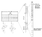
- FIG. 39 is a diagram briefly showing a configuration of performing RE mapping for the first 7 REs first for the HARQ-ACK and subsequently performing RE mapping for the 25 REs for the CSI.
- FIG. 40 is a diagram briefly illustrating an operation of emptying front REs and performing RE mapping in consideration of HARQ-ACK transmission resources when the UE performs RE mapping for CSI.
- FIG. 41 is a diagram illustrating a configuration in which a UE performs UCI mapping in the order of HARQ-ACK-> CSI part 1-> CSI part 2-> data.
- FIG. 42 is a diagram illustrating a UCI mapping configuration in a case where a PUSCH length is 12 OFDM symbols and a DM-RS symbol is present in OFDM symbol indexes # 2 and # 11, respectively.
- 43 to 49 are views illustrating examples of applying PUSCH puncturing or rate matching for HARQ-ACK.
- 50 is a diagram briefly showing a UCI mapping method when the method in Case 6 is applied to each frequency hop in the present invention.
- 52 is a diagram illustrating a configuration of a terminal and a base station in which proposed embodiments can be implemented.
- each component or feature may be considered to be optional unless otherwise stated.
- Each component or feature may be embodied in a form that is not combined with other components or features.
- some of the components and / or features may be combined to form an embodiment of the present invention.
- the order of the operations described in the embodiments of the present invention may be changed. Some components or features of one embodiment may be included in another embodiment, or may be replaced with corresponding components or features of another embodiment.
- the base station is meant as a terminal node of a network that directly communicates with a mobile station.
- the specific operation described as performed by the base station in this document may be performed by an upper node of the base station in some cases.
- various operations performed for communication with a mobile station in a network consisting of a plurality of network nodes including a base station may be performed by the base station or network nodes other than the base station.
- the 'base station' may be replaced by terms such as a fixed station, a Node B, an eNode B (eNB), an advanced base station (ABS), or an access point.
- a terminal may be a user equipment (UE), a mobile station (MS), a subscriber station (SS), or a mobile subscriber station (MSS). It may be replaced with terms such as a mobile terminal or an advanced mobile station (AMS).
- UE user equipment
- MS mobile station
- SS subscriber station
- MSS mobile subscriber station
- AMS advanced mobile station
- the transmitting end refers to a fixed and / or mobile node that provides a data service or a voice service
- the receiving end refers to a fixed and / or mobile node that receives a data service or a voice service. Therefore, in uplink, a mobile station may be a transmitting end and a base station may be a receiving end. Similarly, in downlink, a mobile station may be a receiving end and a base station may be a transmitting end.
- Embodiments of the present invention may be supported by standard documents disclosed in at least one of the IEEE 802.xx system, the 3rd Generation Partnership Project (3GPP) system, the 3GPP LTE system, and the 3GPP2 system, which are wireless access systems, and in particular, the present invention.
- Embodiments of the may be supported by 3GPP TS 36.211, 3GPP TS 36.212, 3GPP TS 36.213, 3GPP TS 36.321 and 3GPP TS 36.331 documents. That is, obvious steps or portions not described among the embodiments of the present invention may be described with reference to the above documents.
- all terms disclosed in the present document can be described by the above standard document.
- Transmission Opportunity Period may be used in the same meaning as the term transmission period, transmission burst (Tx burst) or RRP (Reserved Resource Period).
- LBT process may be performed for the same purpose as a carrier sensing process, a clear channel access (CCA), and a channel access procedure (CAP) for determining whether a channel state is idle.
- CCA clear channel access
- CAP channel access procedure
- 3GPP LTE / LTE-A system will be described as an example of a wireless access system in which embodiments of the present invention can be used.
- CDMA code division multiple access
- FDMA frequency division multiple access
- TDMA time division multiple access
- OFDMA orthogonal frequency division multiple access
- SC-FDMA single carrier frequency division multiple access
- CDMA may be implemented with a radio technology such as Universal Terrestrial Radio Access (UTRA) or CDMA2000.
- TDMA may be implemented with wireless technologies such as Global System for Mobile communications (GSM) / General Packet Radio Service (GPRS) / Enhanced Data Rates for GSM Evolution (EDGE).
- GSM Global System for Mobile communications
- GPRS General Packet Radio Service
- EDGE Enhanced Data Rates for GSM Evolution
- OFDMA may be implemented in a wireless technology such as IEEE 802.11 (Wi-Fi), IEEE 802.16 (WiMAX), IEEE 802-20, Evolved UTRA (E-UTRA).
- UTRA is part of the Universal Mobile Telecommunications System (UMTS).
- 3GPP Long Term Evolution (LTE) is part of an Evolved UMTS (E-UMTS) using E-UTRA, and employs OFDMA in downlink and SC-FDMA in uplink.
- LTE-A (Advanced) system is an improved system of the 3GPP LTE system.
- embodiments of the present invention will be described based on the 3GPP LTE / LTE-A system, but can also be applied to IEEE 802.16e / m system and the like.
- a terminal receives information from a base station through downlink (DL) and transmits information to the base station through uplink (UL).
- the information transmitted and received by the base station and the terminal includes general data information and various control information, and various physical channels exist according to the type / use of the information they transmit and receive.
- FIG. 1 is a diagram for explaining physical channels that can be used in embodiments of the present invention and a signal transmission method using the same.
- the initial cell search operation such as synchronizing with the base station is performed in step S11.
- the UE receives a Primary Synchronization Channel (P-SCH) and a Secondary Synchronization Channel (S-SCH) from the base station, synchronizes with the base station, and obtains information such as a cell ID.
- P-SCH Primary Synchronization Channel
- S-SCH Secondary Synchronization Channel
- the terminal may receive a physical broadcast channel (PBCH) signal from the base station to obtain broadcast information in a cell.
- PBCH physical broadcast channel
- the terminal may receive a downlink reference signal (DL RS) in the initial cell search step to confirm the downlink channel state.
- DL RS downlink reference signal
- the UE After completing the initial cell search, the UE receives a physical downlink control channel (PDCCH) and a physical downlink control channel (PDSCH) according to the physical downlink control channel information in step S12. Specific system information can be obtained.
- PDCCH physical downlink control channel
- PDSCH physical downlink control channel
- the terminal may perform a random access procedure as in steps S13 to S16 to complete the access to the base station.
- the UE transmits a preamble through a physical random access channel (PRACH) (S13), a response message to the preamble through a physical downlink control channel and a corresponding physical downlink shared channel. Can be received (S14).
- PRACH physical random access channel
- the UE may perform contention resolution such as transmitting an additional physical random access channel signal (S15) and receiving a physical downlink control channel signal and a corresponding physical downlink shared channel signal (S16). Procedure).
- the UE After performing the above-described procedure, the UE subsequently receives a physical downlink control channel signal and / or a physical downlink shared channel signal (S17) and a physical uplink shared channel (PUSCH) as a general uplink / downlink signal transmission procedure.
- a transmission (Uplink Shared Channel) signal and / or a Physical Uplink Control Channel (PUCCH) signal may be transmitted (S18).
- UCI uplink control information
- HARQ-ACK / NACK Hybrid Automatic Repeat and reQuest Acknowledgement / Negative-ACK
- SR Scheduling Request
- CQI Channel Quality Indication
- PMI Precoding Matrix Indication
- RI Rank Indication
- UCI is generally transmitted periodically through the PUCCH, but may be transmitted through the PUSCH when control information and traffic data should be transmitted at the same time.
- the UCI may be aperiodically transmitted through the PUSCH by the request / instruction of the network.
- FIG. 2 shows a structure of a radio frame used in embodiments of the present invention.
- the type 1 frame structure can be applied to both full duplex Frequency Division Duplex (FDD) systems and half duplex FDD systems.
- FDD Frequency Division Duplex
- One subframe is defined as two consecutive slots, and the i-th subframe includes slots corresponding to 2i and 2i + 1. That is, a radio frame consists of 10 subframes.
- the time taken to transmit one subframe is called a transmission time interval (TTI).
- the slot includes a plurality of OFDM symbols or SC-FDMA symbols in the time domain and a plurality of resource blocks in the frequency domain.
- One slot includes a plurality of orthogonal frequency division multiplexing (OFDM) symbols in the time domain. Since 3GPP LTE uses OFDMA in downlink, the OFDM symbol is for representing one symbol period. The OFDM symbol may be referred to as one SC-FDMA symbol or symbol period.
- a resource block is a resource allocation unit and includes a plurality of consecutive subcarriers in one slot.
- 10 subframes may be used simultaneously for downlink transmission and uplink transmission during each 10ms period. At this time, uplink and downlink transmission are separated in the frequency domain.
- the terminal cannot simultaneously transmit and receive.
- the structure of the radio frame described above is just one example, and the number of subframes included in the radio frame, the number of slots included in the subframe, and the number of OFDM symbols included in the slot may be variously changed.
- the type 2 frame includes a special subframe consisting of three fields: a downlink pilot time slot (DwPTS), a guard period (GP), and an uplink pilot time slot (UpPTS).
- DwPTS downlink pilot time slot
- GP guard period
- UpPTS uplink pilot time slot
- the DwPTS is used for initial cell search, synchronization or channel estimation in the terminal.
- UpPTS is used for channel estimation at the base station and synchronization of uplink transmission of the terminal.
- the guard period is a period for removing interference generated in the uplink due to the multipath delay of the downlink signal between the uplink and the downlink.
- Table 1 below shows the structure of the special frame (length of DwPTS / GP / UpPTS).
- FIG. 3 is a diagram illustrating a resource grid for a downlink slot that can be used in embodiments of the present invention.
- one downlink slot includes a plurality of OFDM symbols in the time domain.
- one downlink slot includes seven OFDM symbols, and one resource block includes 12 subcarriers in a frequency domain, but is not limited thereto.
- Each element on the resource grid is a resource element, and one resource block includes 12 ⁇ 7 resource elements.
- the number NDL of resource blocks included in the downlink slot depends on the downlink transmission bandwidth.
- the structure of the uplink slot may be the same as the structure of the downlink slot.
- FIG. 4 shows a structure of an uplink subframe that can be used in embodiments of the present invention.
- an uplink subframe may be divided into a control region and a data region in the frequency domain.
- the control region is allocated a PUCCH carrying uplink control information.
- a PUSCH carrying user data is allocated.
- one UE does not simultaneously transmit a PUCCH and a PUSCH.
- the PUCCH for one UE is allocated an RB pair in a subframe. RBs belonging to the RB pair occupy different subcarriers in each of the two slots.
- the RB pair assigned to this PUCCH is said to be frequency hopping at the slot boundary.
- FIG. 5 shows a structure of a downlink subframe that can be used in embodiments of the present invention.
- up to three OFDM symbols from the OFDM symbol index 0 in the first slot in the subframe are control regions to which control channels are allocated, and the remaining OFDM symbols are data regions to which the PDSCH is allocated. to be.
- a downlink control channel used in 3GPP LTE includes a Physical Control Format Indicator Channel (PCFICH), a PDCCH, and a Physical Hybrid-ARQ Indicator Channel (PHICH).
- PCFICH Physical Control Format Indicator Channel
- PDCCH Physical Hybrid-ARQ Indicator Channel
- PHICH Physical Hybrid-ARQ Indicator Channel
- the PCFICH is transmitted in the first OFDM symbol of a subframe and carries information about the number of OFDM symbols (ie, the size of the control region) used for transmission of control channels within the subframe.
- the PHICH is a response channel for the uplink and carries an ACK (Acknowledgement) / NACK (Negative-Acknowledgement) signal for a hybrid automatic repeat request (HARQ).
- Control information transmitted through the PDCCH is called downlink control information (DCI).
- the downlink control information includes uplink resource allocation information, downlink resource allocation information or an uplink transmission (Tx) power control command for a certain terminal group.
- a user equipment has been defined to report channel state information (CSI) to a base station (BS or eNB).
- CSI channel state information
- BS base station
- eNB base station
- the channel state information collectively refers to information representing the quality of a radio channel (or link) formed between the UE and the antenna port.
- the channel state information may include a rank indicator (RI), a precoding matrix indicator (PMI), a channel quality indicator (CQI), and the like.
- RI rank indicator
- PMI precoding matrix indicator
- CQI channel quality indicator
- RI represents rank information of a corresponding channel, which means the number of streams received by the UE through the same time-frequency resource. This value is determined dependent on the long term fading of the channel.
- the RI may then be fed back to the BS by the UE in a period longer than PMI and CQI.
- PMI is a value reflecting channel spatial characteristics and indicates a precoding index preferred by the UE based on a metric such as SINR.
- CQI is a value indicating the strength of a channel and generally refers to a reception SINR obtained when a BS uses PMI.
- the base station sets a plurality of CSI processes to the UE, and can receive the CSI report for each process from the UE.
- the CSI process is composed of CSI-RS for signal quality specification from a base station and CSI-interference measurement (CSI-IM) resources for interference measurement.
- CSI-IM CSI-interference measurement
- the serving cell may request RRM measurement information, which is a measurement value for performing an RRM operation, to the UE.
- RRM measurement information which is a measurement value for performing an RRM operation
- the UE may measure and report information such as cell search information, reference signal received power (RSRP), and reference signal received quality (RSRQ) for each cell.
- the UE receives 'measConfig' as a higher layer signal for RRM measurement from the serving cell, and the UE may measure RSRP or RSRQ according to the information of the 'measConfig'.
- RSRP reference to Physical Uplink Reference Signal
- RSRQ reference to Physical Uplink Reference Signal
- RSSI RSSI
- RSRP is defined as the linear average of the power contribution (in [W] units) of the resource elements that transmit the cell-specific reference signal in the measured frequency band under consideration.
- Reference signal received power (RSRP) is defined as the linear average over the power contributions (in [W]) of the resource elements that carry cell-specific reference signals within the considered measurement frequency bandwidth.
- the cell-specific reference signal R 0 may be utilized for this purpose. (For RSRP determination the cell-specific reference signals R 0 shall be used.) If the UE detects that the cell-specific reference signal R 1 is available, the UE may additionally use R 1 to determine RSRP. (If the UE can reliably detect that R 1 is available it may use R 1 in addition to R 0 to determine RSRP.)
- the reference point for RSRP may be the antenna connector of the UE. (The reference point for the RSRP shall be the antenna connector of the UE.)
- the value reported should not be less than the RSRP corresponding to the individual diversity branch. (If receiver diversity is in use by the UE, the reported value shall not be lower than the corresponding RSRP of any of the individual diversity branches.)
- RSRQ is defined as N * RSRP / (E-UTRA carrier RSSI) as a ratio of RSRP to E-UTRA carrier RSSI.
- RSRQ Reference Signal Received Quality
- N is the number of RB's of the E-UTRA carrier RSSI measurement bandwidth.
- the E-UTRA Carrier RSSI is used in the measurement bandwidth, across N resource blocks, for received signals from all sources, including co-channel serving and non-serving cells, adjacent channel interference, thermal noise, and so on. It includes a linear average of the total received power (in [W]) measured by the terminal in OFDM symbols including the reference symbol for antenna port 0 only.
- E-UTRA Carrier Received Signal Strength Indicator comprises the linear average of the total received power (in [W]) observed only in OFDM symbols containing reference symbols for antenna port 0, in the measurement bandwidth, over N number of resource blocks by the UE from all sources, including co-channel serving and non-serving cells, adjacent channel interference, thermal noise etc.) If higher layer signaling indicates some subframes for RSRQ measurement, the indicated sub RSSI is measured for all OFDM symbols in the frames. (If higher-layer signaling indicates certain subframes for performing RSRQ measurements, then RSSI is measured over all OFDM symbols in the indicated subframes.)
- the reference point for RSRQ may be an antenna connector of the UE. (The reference point for the RSRQ shall be the antenna connector of the UE.)
- the reported value should not be less than the RSRQ corresponding to the individual diversity branch. (If receiver diversity is in use by the UE, the reported value shall not be lower than the corresponding RSRQ of any of the individual diversity branches.)
- RSSI is then defined as the received wideband power including thermal noise within the bandwidth defined by the receiver pulse shape filter and noise generated at the receiver.
- RSSI Received Signal Strength Indicator
- the reference point for the measurement may be the antenna connector of the UE. (The reference point for the measurement shall be the antenna connector of the UE.)
- the reported value should not be smaller than the UTRA carrier RSSI corresponding to the individual diversity branch. (If receiver diversity is in use by the UE, the reported value shall not be lower than the corresponding UTRA carrier RSSI of any of the individual receive antenna branches.)
- the UE operating in the LTE system includes information related to allowed measurement bandwidth (IE) related to the allowed measurement bandwidth transmitted in (system information block type 3) in SIB3 in case of intra-frequency measurement.
- IE allowed measurement bandwidth
- RSRP can be measured at the bandwidth indicated by element).
- the terminal may perform at a bandwidth corresponding to one of 6, 15, 25, 50, 75, and 100 RB (resource block) indicated through the allowed measurement bandwidth transmitted in SIB5.
- RSRP can be measured.
- the terminal can measure RSRP in the frequency band of the downlink (DL) system as a default operation.
- the terminal when the terminal receives information on the allowed measurement bandwidth, the terminal may consider the value as the maximum measurement bandwidth and may freely measure the value of RSRP within the value. However, if the serving cell transmits the IE defined by the WB-RSRQ to the terminal and the allowed measurement bandwidth is set to 50 RB or more, the terminal should calculate the RSRP value for the total allowed measurement bandwidth. Meanwhile, when measuring the RSSI, the terminal measures the RSSI using the frequency band of the receiver of the terminal according to the definition of the RSSI bandwidth.
- MTC Massive Machine Type Communications
- a new wireless access technology system has been proposed as a new wireless access technology that considers such enhanced mobile broadband communication, massive MTC, and ultra-reliable and low latency communication (URLLC).
- the technology is referred to as New RAT or NR (New Radio) for convenience.
- ⁇ and cyclic prefix information for each carrier bandwidth part may be signaled for each downlink (DL) or uplink (UL).
- DL downlink
- UL uplink
- star ⁇ and cyclic prefix information for a downlink carrier bandwidth part may be signaled through higher layer signaling DL-BWP-mu and DL-MWP-cp.
- star ⁇ and cyclic prefix information for an uplink carrier bandwidth part may be signaled through higher layer signaling UL-BWP-mu and UL-MWP-cp.
- Downlink and uplink transmission consists of a frame of 10ms long.
- the frame may be composed of 10 subframes of length 1ms. In this case, the number of consecutive OFDM symbols for each subframe is to be.
- Each frame may consist of two equally sized half frames.
- each half-frame may be configured of subframes 0-4 and subframes 5-9, respectively.
- slots are in ascending order within one subframe. Numbered as in ascending order within a frame It may be numbered as follows. In this case, the number of consecutive OFDM symbols in one slot ( ) Can be determined according to the circulation translocation as shown in the table below. Start slot in one subframe ( ) Is the starting OFDM symbol () in the same subframe ) And time dimension. Table 3 below shows the number of OFDM symbols per slot / frame / subframe for a normal cyclic prefix, and Table 4 shows slots / frame bells / for an extended cyclic prefix. This indicates the number of OFDM symbols per subframe.
- a self-contained slot structure may be applied as the slot structure as described above.
- FIG. 6 is a diagram illustrating a self-contained slot structure applicable to the present invention.
- the base station and the UE may sequentially perform DL transmission and UL transmission in one slot, and may transmit and receive DL data and transmit and receive UL ACK / NACK for the DL data in the one slot.
- this structure reduces the time taken to retransmit data in the event of a data transmission error, thereby minimizing the delay of the final data transfer.
- a time gap of a certain length is required for the base station and the UE to switch from the transmission mode to the reception mode or from the reception mode to the transmission mode.
- some OFDM symbols at the time of switching from DL to UL in the independent slot structure may be set to a guard period (GP).
- the independent slot structure includes both the DL control region and the UL control region.
- the control regions may be selectively included in the independent slot structure.
- the independent slot structure according to the present invention may include not only a case in which both the DL control region and the UL control region are included as shown in FIG. 6, but also a case in which only the DL control region or the UL control region is included.
- a slot may have various slot formats.
- the OFDM symbol of each slot may be classified into downlink (denoted 'D'), flexible (denoted 'X'), and uplink (denoted 'U').
- the UE may assume that downlink transmission occurs only in 'D' and 'X' symbols. Similarly, in the uplink slot, the UE may assume that uplink transmission occurs only in the 'U' and 'X' symbols.
- millimeter wave the short wavelength allows the installation of multiple antenna elements in the same area. That is, since the wavelength is 1 cm in the 30 GHz band, a total of 100 antenna elements can be installed in a 2-dimension array at 0.5 lambda intervals on a 5 * 5 cm panel. Accordingly, in millimeter wave (mmW), a plurality of antenna elements may be used to increase beamforming (BF) gain to increase coverage or to increase throughput.
- BF beamforming
- each antenna element may include a TXRU (Transceiver Unit) to enable transmission power and phase adjustment for each antenna element.
- TXRU Transceiver Unit
- each antenna element may perform independent beamforming for each frequency resource.
- hybrid beamforming having B TXRUs which is smaller than Q antenna elements, may be considered as an intermediate form between digital beamforming and analog beamforming.
- the direction of the beam that can be transmitted at the same time may be limited to B or less.
- the TXRU virtualization model represents the relationship between the output signal of the TXRU and the output signal of the antenna element.
- FIG. 7 is a diagram illustrating how a TXRU is connected to a sub-array. In the case of FIG. 7, the antenna element is connected to only one TXRU.
- FIG. 8 shows how TXRU is connected to all antenna elements.
- the antenna element is connected to all TXRUs.
- the antenna element requires a separate adder as shown in FIG. 8 to be connected to all TXRUs.
- W represents the phase vector multiplied by an analog phase shifter.
- W is a main parameter that determines the direction of analog beamforming.
- the mapping between the CSI-RS antenna port and the TXRUs may be 1: 1 or 1: 1-to-many.
- the beamforming focusing is difficult, but there is an advantage that the entire antenna configuration can be configured at a low cost.
- analog beamforming refers to an operation of performing precoding (or combining) in the RF stage.
- the baseband stage and the RF stage respectively perform precoding (or combining). This reduces the number of RF chains and the number of Digital-to-Analog (D / A) (or Analog-to-Digital) converters while delivering near-digital beamforming performance.
- D / A Digital-to-Analog
- the hybrid beamforming structure may be represented by N transceiver units (TXRUs) and M physical antennas.
- TXRUs transceiver units
- the digital beamforming for the L data layers to be transmitted by the transmitter may be represented by an N * L (N by L) matrix.
- the converted N digital signals are converted into analog signals through TXRU, and analog beamforming is applied to the converted signals represented by an M * N (M by N) matrix.
- FIG. 9 is a diagram illustrating a hybrid beamforming structure from a TXRU and a physical antenna perspective according to an example of the present invention.
- the number of digital beams is L and the number of analog beams is N in FIG. 9.
- the base station is designed to change the analog beamforming in units of symbols and considers a method for supporting more efficient beamforming for a terminal located in a specific region.
- specific N TXRU and M RF antennas as one antenna panel as shown in FIG. 9, in the NR system according to the present invention, a plurality of antenna panels to which hybrid beamforming independent of each other can be applied are defined. It is also considered to adopt.
- the analog beams advantageous for signal reception may be different for each terminal. Accordingly, in the NR system to which the present invention is applicable, the base station transmits a signal (at least a synchronization signal, system information, paging, etc.) by applying a different analog beam for each symbol in a specific subframe (SF) so that all terminals can receive the signal. Beam sweeping operations are being contemplated that allow for receiving opportunities.
- FIG. 10 is a diagram briefly illustrating a beam sweeping operation of a synchronization signal and system information in a downlink (DL) transmission process according to an embodiment of the present invention.
- a physical resource (or physical channel) through which system information of an NR system to which the present invention is applicable is transmitted in a broadcasting manner is referred to as a physical broadcast channel (xPBCH).
- xPBCH physical broadcast channel
- analog beams belonging to different antenna panels in one symbol may be transmitted simultaneously.
- a configuration for measuring channels for analog beams is applied to transmit a reference signal (Reference signal,
- Reference signal The introduction of beam reference signals (Beam RS, BRS), which is RS, is under discussion.
- the BRS may be defined for a plurality of antenna ports, and each antenna port of the BRS may correspond to a single analog beam.
- the synchronization signal or the xPBCH may be transmitted by applying all the analog beams in the analog beam group so that any terminal can receive well.
- UCI uplink control information
- PUSCH physical uplink shared channel
- the terminal In the conventional LTE system, by reducing the PAPR (Peak to Average Power Ratio), the terminal supports a configuration that supports UL data transmission with higher transmission power. This can increase UL coverage. Therefore, in the conventional LTE system, a single carrier property (SC-FDMA) or a Discrete Fourier Transform-spread-OFDM (DFT-s-OFDM) based transmission scheme having a single carrier property is applied.
- SC-FDMA scheme is a scheme of applying DFT precoding (or DFT spreading) to data at the front end of an Inverse Discrete Fourier Transform (IDFT) (or Inverse Fast Fourier Transform) process according to the OFDM scheme.
- the terminal After the terminal generates M data on the time axis, the terminal undergoes processing of an M-point DFT block and an N-point IDFT block (where N ⁇ M). In this case, the time axis data of the terminal is converted into a time axis signal upsampled at an N / M ratio, thereby satisfying a single carrier characteristic.
- PUSCH transmission based on CP-OFDM Cyclic Prefix-OFDM, that is, an OFDM scheme in which a DFT block is applied to data in the OFDM front end
- CP-OFDM-based PUSCH transmission when CP-OFDM-based PUSCH transmission is performed as described above, the NR system may support data and RS resource mapping that are relatively free under a single carrier characteristic constraint. Through this, there is an advantage that the RS overhead can be minimized according to the channel.
- the UE may support both of the above schemes as a PUSCH transmission scheme.
- the UE may perform CP-OFDM-based PUSCH transmission when short UL coverage is sufficient according to the configuration of the base station, and may perform SC-OFDM-based PUSCH transmission when long UL coverage is required.
- a service such as URLLC may have an ultra-low latency requirement. Therefore, in some cases, URLLC data may be transmitted in a form in which previously transmitted eMBB data is punctured. For example, when the UE receives the PUSCH1 transmission instruction according to the eMBB service and subsequently receives the PUSCH2 transmission instruction according to the URLLC service in the PUSCH1 transmission target slot, the UE punctures some PUSCH1 data in the slot. PUSCH2 may be transmitted.
- UCI piggyback in which UCI is transmitted through a PUSCH region may be applied.
- the UCI mapping scheme in the PUSCH may be differently applied depending on whether the PUSCH transmission scheme is a CP-OFDM scheme or an SC-FDMA scheme.
- the UCI mapping method may be designed differently in consideration of puncturing due to other services such as URLLC.
- dynamic control information may mean a dynamic control signal.
- a resource element may be expressed in a grid form of an OFDM resource as a time resource and a subcarrier resource as a frequency resource. Accordingly, the RE may mean a resource corresponding to a specific subcarrier and a specific OFDM symbol.
- a demodulation reference signal may refer to a reference signal that supports a reception operation such as channel estimation for data demodulation.
- a slot means a basic time unit for data scheduling, and may be composed of a plurality of symbols.
- the mini slot may be defined to have a shorter time interval than the slot as a minimum time unit for data scheduling.
- the symbol may mean an OFDM symbol or an SC-FDMA symbol.
- time-first mapping (or frequency-first mapping) is applied to a specific frequency resource (or time resource) when performing RE mapping on the corresponding information.
- This may mean a method of first performing RE allocation in the direction of the time axis (or frequency axis), and then performing RE allocation in the direction of the time axis (or frequency axis) for another frequency resource (or time resource).
- the number on the RE to which the UCI is assigned means the order of mapping the UCI to the RE.
- the UE When the UE performs UCI piggyback with PUSCH, the UE combines the coded data bits and the coded UCI bits in the pre-modulation step for the coded bits to be transmitted to the PUSCH, and then combines the coded UCI bits. Signals obtained by modulating the coded bits may be mapped to RE and transmitted to the PUSCH.
- the UE may combine the coded data bit and the coded UCI bit by one of the following methods. .
- the M bit information punctured with respect to the coded data bits may be sequential M bit information in a direction from least significant bit (LSB) to most significant bit (MSB).
- LSB least significant bit
- MSB most significant bit
- the length of the coded UCI bits may be limited to have a bit size expressed as a multiple of K.
- data and UCI may be divided into RE units, and additional power allocation for the UCI transmission RE may be applied.
- bit-level interleaving is applied in the process of combining the coded data bits and the coded UCI bits, and then symbol level interleaving is additionally applied to RE mapping to a modulated symbol. Can be.
- FIG. 11 is a diagram briefly showing a first UCI transmission method according to the present invention.
- a coded bit that can be transmitted in a PUSCH is N bits and a coded UCI bit is an M bit.
- the UE punctures some M bits of the coded data bits in the pre-modulation step (ie, the front of the modulator block), and codes the coded UCI bits and the coded data bits.
- the modulated signal may be transmitted by PUSCH after modulating the combined coded bits.
- the UE may combine the coded UCI bits after rate-matching such that the length of the coded data bits is (N-M) bits. .
- the interleaved effect in the RE mapping process of the coded bits may be equally applied to the UCI as well as the data.
- a time / frequency diversity gain can be obtained during UCI transmission.
- the coded UCI bits may be transmitted in a distributed manner in the CBs or CBGs.
- the coded bits that can be transmitted in the PUSCH are N bits
- the coded UCI bits are M bits
- the number of CBGs is L
- the UE may combine the coded data bits and the coded UCI bits as follows. have.
- a resource element means a resource corresponding to one subcarrier of one OFDM symbol
- a resource block (RB) or a physical resource block (PRB) is M 1 (eg, 7 or 14) on a time axis.
- M 1 eg, 7 or 14
- a channel coding chain according to the following series of processes may be defined.
- TB transport block
- TBS transport block size
- a sub-block interleaver that mixes the order between the bits in each bit group may be applied. Thereafter, additional interleaving between each bit group may be applied.
- Each CB-specific coded bit is input to the (Circular) buffer according to a specific order (e.g., systematic bit-> parity bit), and the data transmission channel from a specific start point in the (Circular) buffer. Selects a series of coded bits that correspond to the amount of bits (per CB) that can be sent by CB.
- the specific start time point in the (circulation) buffer may be indicated through a DL scheduling DCI or a redundancy version (RV) in the DL scheduling DCI.
- RV redundancy version
- index (k 0 ) mod K index (k 0 + 1) mod K,... , L bits corresponding to index (k 0 + L) mod K may be selected.
- index k 0 denotes a time point indicated by DCI or RV
- K denotes the total size of the circular buffer.
- the coded UCI bits may be distributed to the CBs (or CBGs).
- the UE may puncture the bit stream coming from the output of the (circulating) buffer from the back and insert (partly) coded UCI bits. have.
- the output of the circular buffer is composed of the front part of the systematic bit and the back part of the parity bit, and the puncturing according to the (partial) coded UCI bit insertion is applied mainly on the parity bit. do.
- the UE performs the last bit of the parity bit (based on the order between bits in the (circulating) buffer input bit stream) for the bit stream coming out of the output of the (cyclic) buffer.
- UCI can be inserted while puncturing the data (in the reverse order of the bits in the buffer input bit stream). That is, the UE may replace the UCI from the last bit of the parity bits of the (circulation) buffer.
- FIG. 12 is a diagram illustrating an operation of inserting a UCI while puncturing data from the last bit (based on the order between bits in the (circulating) buffer input bit stream) for the output bit stream of the (circulating) buffer according to a specific RV value. Is a simplified diagram.
- the UE may distribute the UCI for the entire coded CB.
- the UE may perform rate matching or puncturing on the data bits in the coded CB, and may operate as follows.
- the UE when the UE performs puncturing, the UE transmits one UCI bit information per (NM) / Mth CB bits. Can be replaced by a bit.
- the UE may perform RE mapping in a frequency-first (or time-first) manner to a PUSCH resource allocated to the modulated symbols.
- the RE mapping of the frequency-first (or time-first) method first performs RE mapping on a frequency axis (or time axis) resource, and then the frequency axis resource (or frequency) in the following order on the time axis (or frequency axis).
- Time axis means a method of performing RE mapping to a resource.
- the RE mapping order on the frequency axis (or time axis) resource may follow a frequency axis index or follow a specific pattern.
- N and M may be calculated in units of modulation symbols rather than bits.
- FIG. 13 is a simplified diagram of a method for distributing UCI over an entire coded CB based on puncturing or rate matching (for data bits in a coded CB).
- the UE when a bit interleaver (per CB) (i.e., interleaving bits in the CB) is applied to each CB for code blocks generated after the channel coding process, the UE performs UCI piggyback as follows. Can be performed.
- Rate matching for each CB is performed corresponding to the coded UCI bit (per CB)
- ≪ 4 Modulate the (interleaved) coded bit and map it to REs in a PUSCH.
- the RE mapping may be the same as the RE mapping process in the PUSCH (eg, UL-SCH).
- the following UCI mapping method may be considered.
- Method # 1 Map 4M REs to the first symbol (in symbol order), then move on to the next symbol
- RE index in symbol #A ((0 + m + A) mod 12M, (3M + m + A) mod 12M, (6M + m + A) mod 12M, (9M + m + A) mod 12M ⁇ or ⁇ (0 + m + A * M) mod 12M, (3M + m + A * M) mod 12M, (6M + m + A * M) mod 12M, (9M + m + A * M) mod 12M ⁇
- mapping of the first 4 REs (0M, 3M, 6M, 9M) of the 4M RE indices (in terms of UCI RE mapping) may be as follows.
- mapping can be in the following order:
- M is the number of RBs assigned to the PUSCH and / or the number of symbols assigned to the PUSCH (except DMRS) and / or the Modulation and Coding Scheme (MCS) and / or UCI coding bits indicated in the PUSCH. coded bits) and / or the number of UCI coded modulation symbols (RE).
- the M may be determined by the number of RBs allocated to the PUSCH.
- Method # 2 Map 12M REs to the first symbol (in symbol order) and move on to the next symbol
- RE index in symbol #A ((0 + m + A) mod 12M, (3M + m + A) mod 12M, (6M + m + A) mod 12M, (9M + m + A) mod 12M ⁇ or ⁇ (0 + m + A * M) mod 12M, (3M + m + A * M) mod 12M, (6M + m + A * M) mod 12M, (9M + m + A * M) mod 12M ⁇
- mapping of the first 4 REs (0, 3M, 6M, 9M) among the 12M RE indexes may be performed in the following order.
- mapping can be in the following order:
- M is the number of RBs assigned to the PUSCH and / or the number of symbols assigned to the PUSCH (except DMRS) and / or the number of MCS and / or UCI coded bits indicated on the PUSCH and / or Or the number of UCI coded modulation symbols (RE).
- the M may be determined by the number of RBs allocated to the PUSCH.
- Method # 3 P clusters (C_0, C_1, C_2, ..., C_ (P-1)) are defined in the frequency axis direction, and UCI is RE mapped to the P clusters as follows.
- P the number of clusters, may be set by the base station.
- the RE index in cluster C_A [k] (Local in PUSCH) is A [k] * M + (Q mod M) (or (A [k] +1) * M- (Q mod M) -1) Perform RE mapping to RE
- the arrangement A may be one of the following.
- a [k] means a value corresponding to the index k of the array A.
- the RE index in cluster C_A [k] (Local in PUSCH) is A [k] * M + (Q mod M) (or (A [k] +1) * M- (Q mod M) -1) Perform RE mapping to RE
- the array A may be a bit reversal permutation sequence for 2 N.
- a [k] means a value corresponding to the index k of the array A.
- Method # 4 P clusters (C_0, C_1, C_2, ..., C_ (P-1)) are defined in the frequency axis direction, and UCI is mapped to RE for the P clusters as follows.
- M M 0 / P.
- P which is the number of clusters, may be set by the base station.
- V Q mod Perform UCI mapping below for symbols with index N_SYMBOL.
- RE mapping is performed to an RE having a RE index of A [k] * M + W (or A [k] * M-W + M-1) in the cluster C_A [k] (Local in PUSCH).
- N_SYMBOL means the total number of symbols for performing UCI mapping.
- W floor (Q / N_SYMBOL) means.
- the arrangement A may be one of the following.
- a [k] means a value corresponding to the index k of the array A.
- V Q mod Perform UCI mapping below for symbols with index N_SYMBOL.
- RE mapping is performed to an RE having a RE index of A [k] * M + W (or A [k] * M-W + M-1) in the cluster C_A [k] (Local in PUSCH).
- N_SYMBOL means the total number of symbols for performing UCI mapping.
- W floor (Q / N_SYMBOL) means.
- the array A may be a bit reversal permutation sequence for 2 N.
- a [k] means a value corresponding to the index k of the array A.
- Method # 5 P clusters (C_0, C_1, C_2, ..., C_ (P-1)) are defined in the frequency axis direction, and UCI is RE mapped to the P clusters as follows.
- A> subcarriers included in each cluster may be determined by one of the following methods.
- M or P may be a value determined according to a value set by the base station and / or the number of UCI REs.
- Base station configures subcarriers included by cluster (via higher layer signal, etc.).
- P the number of clusters, may be set by the base station.
- UCI mapping order between clusters may be determined by one of the following methods.
- Cluster C_A [0], Cluster C_A [1],... , UCI mapping order between clusters may be defined in the order of Cluster C_A [P-1].
- a [k] means a value corresponding to the index k of the array A.
- the array A may be as follows.
- A may be a bit reversal permutation sequence for 2 N.
- UCI mapping order between subcarriers in a cluster may be determined by one of the following methods.
- Option 1 or Option 2 may be applied according to the frequency axis resource position of the cluster. Specifically, Option 1 may be followed when the cluster is included in the left half frequency region of the PUSCH resource (based on the ascending order of the frequency index), and Option 2 may be followed when the cluster is included in the other half frequency region.
- the UCI mapping order between subcarriers in a cluster means an order in which UCI symbols that are modulated (subject to UCI mapping) are sequentially generated for a corresponding C cluster to fill subcarriers in the cluster.
- the D> UE can perform (cluster-based) UCI mapping in the following manner.
- i> Performs UCI mapping of modulated UCI symbols (within a specific symbol) in the order of inter-cluster UCI mapping for the entire P clusters. However, the UE may perform UCI mapping for one modulated UCI symbol for each cluster in each order.
- the UE may perform one of the following operations.
- Option 1 If S is a specific value, move to the next symbol (in terms of UCI mapping) and perform (cluster-based) UCI mapping for that symbol. Alternatively, perform UCI mapping of UCI symbols remodulated for the current symbol in order of inter-cluster UCI mapping for all P clusters. In this case, when the UE performs UCI mapping for all symbols, the UE moves back to the first symbol and performs (cluster-based) UCI mapping for the symbol.
- Option 2 Perform UCI mapping in the order of inter-cluster UCI mapping for all P clusters with the modulated UCI symbols until the UCI mapping for all (frequency) resources in the current symbol is completed.
- the subcarrier position for the modulated UCI symbol is determined according to the UCI mapping order between subcarriers in the cluster.
- the subcarrier positions to which the series of modulated UCI symbols are UCI mapped may follow the UCI mapping order between subcarriers in the cluster.
- FIG. 14 is a diagram briefly showing a UCI mapping method according to Method # 1 for the first three symbols. In FIG. 14, it is assumed that the order of 0-> 9M-> 3M-> 6M is applied to the first four REs.
- the number means the UCI RE mapping order
- the shaded area means UCI
- the unshaded area means data
- the subcarrier (or frequency) index is increased downward in the figure.
- the symbol (or time index) increases toward the right in the drawing.
- Method 15 is a view briefly showing an example of a UCI mapping method according to Method # 5.
- the UE when the number of clusters is 4, the UE performs UCI mapping between clusters in the order of [Cluster 0-> Cluster 1-> Cluster 2-> Cluster 3], and UCI mapping between subcarriers in the cluster is performed. It may be performed in ascending order of frequency index. In addition, the UE may perform UCI mapping for the next symbol after finishing UCI mapping for all frequency resources (available) in one symbol.
- 16 is a diagram illustrating another example of a UCI mapping method according to Method # 5.
- the UE when the number of clusters is 4, the UE performs UCI mapping between clusters in the order of [Cluster 0-> Cluster 3-> Cluster 2-> Cluster 1], and UCI mapping between subcarriers in the cluster is performed. It may be performed in ascending order of frequency index. In addition, the UE may perform UCI mapping for the next symbol after finishing UCI mapping for all frequency resources (available) in one symbol.
- FIG. 17 is a diagram schematically illustrating another example of a UCI mapping method according to Method # 5.
- FIG. 17 is a diagram schematically illustrating another example of a UCI mapping method according to Method # 5.
- the UE when the number of clusters is 4, the UE performs UCI mapping between clusters in the order of [Cluster 0-> Cluster 1-> Cluster 2-> Cluster 3], and UCI mapping between subcarriers in the cluster is performed. It may be performed in ascending order of frequency index. In addition, the UE may uniformly perform UCI mapping (for four UCI REs) for all clusters in one symbol, and then perform UCI mapping for the next symbol.
- a RE mapping rule for a specific UCI may refer to a position and order of allocation of REs which allocate a coded bit (or coding symbol) for the corresponding UCI. . If the k 1 RE (s) of the second order of allocation in accordance with the RE mapping rule for the UCI is not available, UE skips the RE (s) coded bits for the UCI (coded bit) (or coded symbols) The RE mapping process can be resumed from RE (eg k 1 +1) in the next allocation order.
- the (frequency axis) cluster refers to a set composed of (adjacent) specific subcarriers.
- a resource element (RE) refers to a physical (time / frequency) resource corresponding to one (OFDM) symbol and one subcarrier in an OFDM structure.
- UCI mapping method # 6 When the UE according to the present invention transmits (specific) UCI to the PUSCH (for example, UCI piggyback, or UCI on PUSCH), (for the UCI) (frequency axis) cluster-based RE mapping rules can be applied as follows. have. (Hereinafter referred to as UCI mapping method # 6)
- the subcarriers included in each cluster may be determined by one of the following methods.
- the subcarrier index included in the P-1 ⁇ th cluster (eg, C_L) may be defined as follows based on a local subcarrier index in the PUSCH.
- M or P may be a value determined according to a value set by the base station and / or the number of UCI REs.
- Option 2 The base station sets one or more of the following information (via higher layer signal, etc.), and the UE recognizes the cluster established based on the information (s).
- Cluster (frequency axis) starting point (or subcarrier index)
- Cluster-specific (frequency axis) resources or subcarrier index
- the UE when setting the subcarrier index constituting the cluster per symbol (UCI mapping target), the UE applies a different frequency axis offset for each symbol (target UCI mapping) in addition to the reference cluster (setting) cluster by symbol Can be derived.
- the subcarrier index included in the P-1 ⁇ th cluster (eg, C_L) may be defined as follows based on the local subcarrier index in the PUSCH.
- M or P may be a value determined according to a value set by the base station and / or the number of UCI REs.
- the cluster-to-cluster UCI mapping order may be determined in one of the following ways.
- P cluster (s) may be indexed in ascending (or descending) order of frequency axis. That is, any of the sub-carriers within the L 1 th cluster can be L 2 (> L 1) th cluster, than in any of the sub-carriers on the frequency axis fast always or always late.
- a [0] th Cluster, A [1] th Cluster,... , UCI mapping order between clusters can be defined in order of A [P-1] th Cluster.
- the array A may be equal to one of the following.
- A is a bit reversal permutation sequence for 2 N
- the UCI mapping order between subcarriers in the cluster is determined by the coded UCI bit (or coded UCI symbol). It means the order of filling subcarriers in the cluster.
- the frequency index of the first subcarrier starting the UCI mapping in the cluster may be different for each symbol.
- the first subcarrier index that starts UCI mapping in a cluster may increase (or decrease) proportionally, provided that the final subcarrier index is a modulus for the total number of subcarriers in the cluster. (Modulo) operation can be derived).
- the order of UCI mapping between subcarriers in a cluster may be determined by one of the following methods.
- UCI mapping is performed after (k + 1) mod Mth frequency index after kCI frequency mapping for kth frequency index.
- the UCI mapping for the k th frequency index (k-1) is performed.
- Option 3 Based on the order set by the base station (via higher layer signal)
- UCI mapping order between subcarriers in a cluster may be different depending on the UCI type. For example, in the HARQ-ACK, the UCI mapping order between subcarriers in a cluster may follow an ascending order (or descending order) of frequency indices, and in the CSI, the UCI mapping order between subcarriers in a cluster may follow a descending order (or ascending order) of a frequency index. . (E.g. to prevent the case where CSI is punctured by HARQ-ACK)
- the UE may perform (cluster based) UCI mapping from the first symbol (in terms of UCI mapping) in the following manner.
- Step 1 Perform UCI mapping of the coded UCI bits (or coded UCI symbols) in the order of inter-cluster UCI mapping for all P clusters.
- UCI mapping for the coded UCI bits (or coded symbols) is (in Cluster).
- a coded UCI bit (or coded UCI symbol) allocated to the N th from a specific cluster point of view may be allocated to a subcarrier having an N th allocation order in the UCI mapping order between subcarriers in the cluster.
- the UE may skip to the next cluster in order to perform UCI mapping.
- the UE may skip the UCI mapping in the corresponding RE and allocate the UCI to the UCI mapping target RE in the following order. .
- PT-RS phase tracking reference signal
- Step 2 If the UE has performed Step 1 (for one symbol) S number of times, move to the next symbol (from UCI mapping point of view) and perform Step 1
- S may be the number 1 or the number of times Step 1 is performed until UCI mapping is performed for all available frequency resources (within one symbol).
- the UE may apply one of the following schemes.
- Option 1 You can perform Step 1 again from the first symbol (in terms of UCI mapping). (I.e., maintain order between UCI mapping target symbols)
- Step 1 You can perform Step 1 in reverse order (from the UCI mapping point of view). (I.e. changing the order between UCI mapping target symbols)
- FIG. 18 is a diagram schematically illustrating an example of a UCI mapping method according to Method # 6.
- the UE when the number of clusters is 4, the UE performs UCI mapping between clusters in the order of [Cluster 0-> Cluster 1-> Cluster 2-> Cluster 3], and the cluster for HARQ-ACK (cluster). Internal) UCI mapping between subcarriers may be performed in ascending order of frequency index, and UCI mapping between (cluster) subcarriers for CSI may be performed in descending order of frequency index.
- FIG. 19 is a diagram schematically showing another example of a UCI mapping method according to Method # 6.
- the UE when performing UCI mapping between symbols, the UE alternately performs UCI mapping including HARQ-ACK and CSI around each hop based on a frequency hopping boundary of the PUSCH. Can be done.
- the method of alternately performing UCI mapping around the frequency hopping boundary may be applied when frequency hopping for the PUSCH is applied or when an additional DM-RS is present in the PUSCH.
- FIG. 20 is a diagram schematically illustrating another example of a UCI mapping method according to Method # 6.
- the UE when the number of clusters is 4, the UE performs UCI mapping between clusters in the order of [Cluster 0-> Cluster 3-> Cluster 1-> Cluster 2], and the cluster for HARQ-ACK (cluster). Internal) UCI mapping between subcarriers may be performed in ascending order of frequency index, and UCI mapping between (cluster) subcarriers for CSI may be performed in descending order of frequency index.
- FIG. 21 is a diagram schematically illustrating another example of a UCI mapping method according to Method # 6.
- FIG. 21 is a diagram schematically illustrating another example of a UCI mapping method according to Method # 6.
- the UE when performing UCI mapping between symbols, the UE alternately performs UCI mapping including HARQ-ACK and CSI around each hop centering on the frequency hopping boundary of the PUSCH. Can be done.
- the method of alternately performing UCI mapping around the frequency hopping boundary may be applied when frequency hopping for the PUSCH is applied or when an additional DM-RS is present in the PUSCH.
- FIG. 22 is a diagram schematically illustrating another example of a UCI mapping method according to Method # 6.
- FIG. 22 is a diagram schematically illustrating another example of a UCI mapping method according to Method # 6.
- the UE when the number of clusters is 4, the UE performs UCI mapping between clusters in the order of [Cluster 0-> Cluster 1-> Cluster 2-> Cluster 3], and the cluster for HARQ-ACK (cluster). Internal) UCI mapping between subcarriers may be performed in ascending order of frequency index, and UCI mapping between (cluster) subcarriers for CSI may be performed in descending order of frequency index.
- each (symbol) cluster for UCI mapping is shifted by one subcarrier as the symbol increases (but modulo operation is applied to the total number of subcarriers in the PUSCH).
- FIG. 23 is a diagram schematically illustrating another example of a UCI mapping method according to Method # 6.
- FIG. 23 is a diagram schematically illustrating another example of a UCI mapping method according to Method # 6.
- the UE performs UCI mapping including HARQ-ACK and CSI alternately at each hop centering on the frequency hopping boundary of the PUSCH when performing UCI mapping between symbols. Can be done.
- the method of alternately performing UCI mapping around the frequency hopping boundary may be applied when frequency hopping for the PUSCH is applied or when an additional DM-RS is present in the PUSCH.
- Step 0 Generate coded CB (CB 1) (with cystematic and parity bits)
- Step 1 Generate coded CB (CB 2) by adding coded UCI bits after performing rate matching or puncturing on parity bits in coded CB (CB 1).
- the UE performs rate matching or puncturing on consecutive bits from the last parity bit, and evenly performs rate matching or puncturing on the plurality of parity bits.
- Step 2 Intra-CB interleaving per / across branch to coded CB (CB 2) to generate (bit-level interleaved) coded CB (CB 3) .
- the UE may perform bit-level interleaving for each parity bit group and then perform bit-level interleaving between parity bit groups.
- Step 3 Perform Frequency-First (or Time-First) RE Mapping (According to CB Index)
- Step 0 Generate coded CB (CB 1) (with cystematic and parity bits)
- Step 1 Intra-CB interleaving per / across branch for coded CB (CB 1) to generate (bit-level interleaved) coded CB (CB 2) .
- the UE may perform bit-level interleaving for each parity bit group and then perform bit-level interleaving between parity bit groups.
- Step 2 Generate coded CB (CB 3) by adding coded UCI bits after performing rate matching or puncturing on parity bits in Coded CB (CB 2).
- the UE performs rate matching or puncturing on consecutive bits from the last parity bit, and evenly performs rate matching or puncturing on the plurality of parity bits.
- Step 3 Perform intra-CB interleaving per / across branch for coded CB (CB 3) to generate (bit-level interleaved) coded CB (CB 4) .
- the UE may perform bit-level interleaving for each parity bit group and then perform bit-level interleaving between parity bit groups.
- Step 4 Perform Frequency-First (or Time-First) RE Mapping (According to CB Index)
- the UE may perform UCI mapping in the following manner.
- Rate matching or puncturing (for Data) in the above process may be performed either before or after interleaving.
- the process may be performed for each CB. Assuming a total of M CBs and a total of N bit UCIs, the UE may add N / M bits of UCI after performing rate matching or puncturing for each CB.
- RE mapping is performed differently from the data for UCI.
- the UE basically performs the above procedure based on the frequency-first method.
- the UE may perform the RE mapping in the order of the distributed form rather than the simple index index in the symbol (or CB).
- rate matching or puncturing (for data) corresponding to N / M-bit UCI for each CB is performed as described above. Can be applied via mapping.
- the UE when the UE applies rate matching (or puncturing) in consideration of the coded bits for UCI (hereinafter referred to as Coded UCI bits) in the process of generating coded bits for data (hereinafter, referred to as Coded Data bits), the UE May combine the coded UCI bits and the coded data bits and then apply (single) RE mapping to the combined coded bits.
- the RE mapping order may be a coded UCI bit-> coded data bit order.
- the length of the coded UCI bits and / or coded data bits may be limited to have a bit size expressed as a multiple of K.
- data and UCI may be distinguished in RE units, and additional power allocation for the UCI transmission RE may be applied.
- the (single) RE mapping scheme may be different according to the waveform for the PUSCH transmission as follows. (Or, the RE mapping scheme below may be applied only to coded UCI bits.)
- one of the frequency-first mapping scheme and the time-first mapping scheme may be preset or set as a higher layer signal by the base station.
- the inter-symbol interleaving may be performed in the form of applying a block interleaver (column-wise permutation applied) to the subcarriers per symbol.
- Interleaving can be applied to each row in the order of increasing column index
- column-wise permutation may be [1 2 3 4 5 6]-> [1 3 5 2 4 6].
- the number k in parentheses means the k th column.
- Interleaving can be applied to each column in increasing row index
- the UE may input 1 to 12 into a 3 by 4 matrix as Row by Row as shown in the following table.
- the output value may be interpreted as an RE mapping in the following order.
- the number means the RE mapping order
- the subcarrier (or frequency) index increases toward the bottom
- the symbol (or time) index increases toward the right.
- the RE mapping order indicates the order in one symbol. Accordingly, the UE performs RE mapping for coded bits corresponding to frequency resources in one symbol (e.g., for a RE symbol for a plurality of symbols, and performs RE mapping for coded bits for a next symbol. Can be performed).
- the RE mapping order of the UE may be defined as shown in the following table. However, in the example below, the number means the RE mapping order, the subcarrier (or frequency) index increases downward, and the symbol (or time) index increases toward the right.
- 24 is a diagram illustrating an example in which a coded UCI bit precedes an RE mapping order than a coded data bit.
- the RE mapping for the UCI may be naturally distributed on the frequency axis.
- the numbers indicate the RE mapping order, the subcarrier (or frequency) index increases downwards and the symbol (or time) index increases toward the right.
- the shaded area means UCI, and the shaded area means data.
- 25 is a diagram illustrating another example in which a coded UCI bit precedes an RE mapping order than a coded data bit.
- UCI has coded bits corresponding to 20 REs and is distributed by coded bits corresponding to 10 REs for two CBs, respectively.
- the RE mapping for the UCI may be naturally distributed on the frequency axis.
- the numbers indicate the RE mapping order, the subcarrier (or frequency) index increases downwards and the symbol (or time) index increases toward the right.
- the shaded area means UCI, and the shaded area means data.
- UCI 1 + CB 1 is mapped to the 1st to 42nd RE
- UCI 2 + CB 2 is mapped to the 43rd to 84th RE.
- the UE performs RE mapping of coded bits to UCI (that is, Coded UCI bits to RE mapping) in a specific symbol.
- the total number of subcarriers allocated in the symbol is N, and a local index from 0 to (N-1) is allocated to the allocated subcarriers (in ascending (or descending order) of the frequency index).
- M may be a value that is a divisor of N and n squared of 2 (or the maximum of such values).
- the M may be determined by the number of PRBs allocated to the PUSCH or by a value set by the base station.
- the UE performs the RE mapping of the coded UCI bits in the same manner as the above scheme (i.e., RE mapping according to a n ) for all frequency resources (assigned as PUSCH resources) in a symbol order, and then performs the next symbol.
- RE mapping of the coded UCI bits may be performed for a frequency resource (assigned as a PUSCH resource) for.
- b n and a n can be obtained as follows.
- the RE mapping order for UCI in one symbol may follow a local index order corresponding to the sequence a n as shown in the following table.
- the subcarrier (or frequency) index increases toward the bottom and the symbol (or time) index increases toward the right.
- the white number in the black shade on the left means the local index order between subcarriers
- the black number in the white on the right means the RE mapping order for UCI.
- the UE performs RE mapping of coded bits to UCI (that is, Coded UCI bits to RE mapping) in a specific symbol.
- the total number of subcarriers allocated in the symbol is N, and a local index from 0 to (N-1) is allocated to the allocated subcarriers (in ascending (or descending order) of the frequency index).
- the UE may define a mapping pattern according to the number of REs (hereinafter referred to as UCI REs) to perform UCI mapping (for a corresponding symbol).
- M when the UCI RE number (for the symbol) is R, M may be defined as in the following equation.
- K may be a predetermined value or a value set by the base station.
- the M value may be determined according to a specific variable value set by the base station or set by the base station and the number of UCI REs.
- the UE performs an RE mapping for the coded UCI bits in the same manner as the above scheme (i.e., RE mapping according to c n ) for all frequency resources (assigned to PUSCH resources) in a symbol order, and then RE mapping of the coded UCI bits may be performed for frequency resources (assigned with PUSCH resources) for the symbol.
- the RE mapping order for the UCI in one symbol may follow the local index order corresponding to the sequence c n as shown in the following table.
- the subcarrier (or frequency) index increases toward the bottom and the symbol (or time) index increases toward the right.
- the white number in the black shade on the left means the local index order between subcarriers
- the black number in the white on the right means the RE mapping order for UCI.
- 26 is a diagram illustrating an example of a UCI RE mapping method according to the present invention.
- the UE fills both end REs of the (available) frequency resources of the first symbol in order, moves to the next symbol, and then again uses the amount of (available) frequency resources.
- a way of filling the final REs in order may also be considered.
- the UE may return to the first symbol again to fill the (available) frequency resource ends REs in order, and then continue with UCI mapping while moving to the next symbol.
- FIG. 26 briefly illustrates the UCI mapping operation of the UE when the UE performs UCI mapping for two (consecutive) symbols.
- a black area means a UCI mapped RE
- a number means a RE mapping order.
- the symbol position to be the target of the UCI RE mapping, and the sub-carrier position to be the target of the UCI RE mapping for each symbol may be previously set or promised by the base station.
- UCI mapping for all subcarriers in two (continuous) symbols is possible.
- the UE may skip the RE and resume UCI mapping from the k + 1 th UCI mapping RE.
- a specific RS transmission eg, PT-RS: phase tracking-reference signal, RS for phase shift correction
- the aforementioned first UCI transmission method may be combined and applied together unless they are mutually arranged with other proposals of the present invention.
- the UE may perform resource mapping for a coded UCI symbol (for example, a modulated symbol) after resource mapping for data is completed as follows.
- the base station sets the UCI mapping order between the plurality of symbols (or symbol sets) and symbols (or symbol sets) for UCI mapping (per subcarrier or subcarrier set) in one of the following ways to the UE:
- the base station sets the UCI mapping order between the plurality of subcarriers (or subcarrier sets) and the subcarriers (or subcarrier sets) for UCI mapping (per symbol or symbol set) in one of the following ways to the UE:
- the UE performs frequency-first UCI mapping for each symbol (or symbol set) in the order of UCI mapping between the symbols (or symbol sets) as follows.
- the UE is coded according to the UCI mapping order between subcarriers (or subcarrier sets) for REs corresponding to a plurality of subcarriers (or subcarrier sets) for the UCI mapping (within a specific symbol or symbol set). Assign symbols sequentially
- the UE performs time-first UCI mapping for each subcarrier (or subcarrier set) as follows in the order of UCI mapping between the subcarriers (or subcarrier sets).
- the UE is UCI coded according to the UCI mapping order between symbols (or symbol sets) for REs corresponding to a plurality of symbols (or symbol sets) for the UCI mapping (within a specific subcarrier or subcarrier set). Assign symbols sequentially
- the base station determines a UCI mapping order between symbols (or symbol sets), subcarriers (or subcarrier sets), symbols (or symbol sets), and UCI mapping order between subcarriers (or subcarrier sets) for the UCI mapping.
- a specific symbol resource or subcarrier resource may be defined in terms of index.
- the UE may puncture some of the data REs and perform UCI mapping on the corresponding REs or apply rate matching to some of the data REs, and perform UCI mapping on the remaining REs in the PUSCH.
- the UCI mapping operation of the terminal may be performed in the virtual time and frequency domain before the DFT precoding is applied.
- whether the terminal applies the frequency-first mapping scheme or the time-first mapping scheme may be determined by one of the following methods.
- the UCI mapping order between UCI mapping target subcarriers in the symbol set (or subcarrier set) is time-first mapping.
- the UCI mapping method applied to the symbol set unit is frequency-first mapping
- the UE may apply a time-first mapping method in the symbol set.
- the UCI mapping method applied to the subcarrier set unit is time-first mapping
- the UE may apply a frequency-first mapping method in a symbol set.
- the UE punctures some data REs in the PUSCH after modulation and resource mapping is finished and performs mapping of coded UCI symbols (eg, modulated symbols) to the REs, or to the data. Rate-matching may be performed to leave some REs in the PUSCH, and then coded UCI symbol mapping may be performed on the corresponding REs.
- coded UCI symbols eg, modulated symbols
- the UE may apply frequency-first scheme UCI mapping in which UCI is first allocated to a frequency axis.
- the UE sets UCI to REG index 1 of 1st symbol (adjacent to DMRS), REG index 1 of next 2nd symbol,... It may be mapped to REG index 1 of the last symbol and then to REG index 2 of the 1st symbol.
- the location between REGs in the same symbol may be in an adjacent form or in a distributed form (in the frequency axis).
- FIG. 27 is a diagram schematically illustrating a UCI mapping method in the case of setting two REs having two subcarrier spacings to one REG.
- the interval between REs (or the interval between the first RE and the last RE in the REG) constituting the REG is smaller than the interval between the start points of the REG.
- FIG. 28 is a diagram briefly showing a UCI mapping method when two REs having two symbol intervals are set to one REG.
- FIG. 28 shows an example in which REG is defined in the time axis direction as a modification of FIG. 27.
- the UE sets UCI (adjacent to DMRS) to REG index 1 of the 1st subcarrier, REG index 1 of the next 2nd subcarrier,. It may be mapped to REG index 1 of the last subcarrier and then to REG index 2 of the 1st subcarrier. In the case of positions between REGs in the same subcarrier, it may be in an adjacent form or in a distributed form (on a time axis).
- FIG. 29 is a diagram schematically illustrating a UCI mapping method when two REs having five subcarrier intervals are set to one REG.
- the UE sets UCI to REG index 1 of 1st symbol (adjacent to DMRS), REG index 1 of next 2nd symbol,... It may be mapped to REG index 1 of the last symbol and then to REG index 2 of the 1st symbol.
- the interval between REs constituting the REG (or the interval between the first RE and the last RE in the REG) may be set to be larger than the interval between the start point of the REG.
- an interval between REs in an REG may be set to five subcarrier intervals or an interval between starting points of an REG may be set to two subcarriers. Accordingly, the UCI may be alternately mapped to REs belonging to different REGs on the frequency axis.
- the interval between REs constituting the REG (or the interval between the first RE and the last RE in the REG) is set to be larger than the interval between the starting point of the REG, the distance between the REs in the REG as well as the distance between the REGs.
- adjacent information in the UCI bit that is largely set and coded may be distributed in the UCI mapping process.
- FIG. 30 is a diagram briefly showing a UCI mapping method in the case of setting two REs having four symbol intervals to one REG.
- the UE sets UCI (adjacent DMRS) to REG index 1 of 1st subcarrier, REG index 1 of next 2nd subcarrier,...
- the REG index 1 of the last subcarrier may be mapped to the REG index 2 of the 1st subcarrier.
- the interval between REs constituting the REG (or the interval between the first RE and the last RE in the REG) may be set to be larger than the interval between the start point of the REG.
- the interval between REs in the REG is set to four symbol intervals, or the interval between start points of the REG is set to two symbol intervals. Accordingly, the UCI may be mapped to REs belonging to different REGs on the time axis in a staggered manner.
- the UE may map the UCI in such a manner that the UCI is alternately mapped to N REGs as the symbol (or subcarrier) index increases. have.
- the UE maps UCI to REG index 1 of 1st symbol (or subcarrier), REG index 2 of next 2nd symbol (or subcarrier), and REG of next 3rd symbol (or subcarrier).
- index 1 For example, when two REGs are alternately mapped, the UE maps UCI to REG index 1 of 1st symbol (or subcarrier), REG index 2 of next 2nd symbol (or subcarrier), and REG of next 3rd symbol (or subcarrier).
- index 1 for example, when two REGs are alternately mapped, the UE maps UCI to REG index 1 of 1st symbol (or subcarrier), REG index 2 of next 2nd symbol (or subcarrier), and REG of next 3rd symbol (or subcarrier).
- index 1 For example, when two REGs are alternately mapped, the UE maps UCI to REG index 1 of 1st symbol (or subcarrier), REG index 2 of next 2nd symbol (or subcarrier), and REG of next 3r
- 31 and 32 are diagrams schematically illustrating an operation in which a UE alternately maps UCI between the REGs when the REG is configured with distributed M REs on the same symbol.
- 33 and 34 are diagrams illustrating an operation in which UEs alternately map UCIs between REGs when REGs are composed of distributed M REs on the same subcarrier.
- FIG. 35 is a diagram illustrating a UCI mapping operation of a UE when the base station allows UCI mapping for the first, fourth, seventh, tenth, and thirteenth symbols to the terminal. In FIG. 35, it is assumed that the UCI mapping order between symbols is determined in ascending order of symbol index.
- the aforementioned second UCI transmission method may be combined and applied together unless they are mutually arranged with other proposals of the present invention.
- the UE When the UE performs UCI piggyback on UCI 1 with PUSCH 1 and performs PUSCH 2 transmission based on mini-slot in the PUSCH 1 transmission slot, the UCI 1 transmission symbols (or UCI 1 mapped to RE) and PUSCH 2 resources may conflict. In this case, the UE may perform one of the following operations.
- the UE transmits a PUSCH (PUSCH 1) for an eMBB service to a slot having a length of 1 ms. Subsequently, it is assumed that the base station instructs the UE to transmit the PUSCH 2 for the URLLC service in a mini slot of less than 1 ms in the PUSCH 1 transmission slot.
- PUSCH 1 PUSCH 1
- the transmission region of PUSCH 1 is redefined to exclude the transmission region of PUSCH 2, and the UE may perform UCI mapping again on the redefined PUSCH 1 transmission resource region.
- such a method may not be a practical method in consideration of a processing time of the UE.
- a method of not allowing PUSCH 2 transmission for a symbol (or mapped REs) in which UCI is transmitted in PUSCH 1 may be considered.
- FIG. 36 illustrates a case in which PUSCH 2 is transmitted from a fourth fifth symbol position to a mini slot having a length of two symbols when PUSCH 1 and UCI are transmitted.
- the UE may transmit by applying puncturing or rate matching to an RE mapped with UCI in PUSCH 1 among transmission resources of PUSCH 2.
- the UE may transmit intact PUSCH 2 without performing puncturing or rate-matching on the RE mapped to the UCI of the PUSCH 1 region for PUSCH 2.
- the UE may apply a PUSCH DM-RS pattern (Pattern B) different from the PUSCH DM-RS pattern (Pattern A) when the UCI is not piggybacked.
- the UE may perform UCI mapping on symbols immediately adjacent to the PUSCH DM-RS according to the Pattern B.
- the pattern B may have a higher DM-RS density than the pattern A.
- FIG. 37 is a diagram illustrating mapping patterns of DM-RSs when a PUSCH is transmitted without a UCI piggyback and when a PUSCH to which a UCI piggyback is applied is transmitted.
- the UE when the UE performs PUSCH transmission without UCI piggyback, as shown in the left figure of FIG. 37, the UE may transmit the DM-RS as one symbol. Or, if the UE performs PUSCH transmission with UCI piggyback applied, as shown in the diagram on the right of FIG. 37, the UE transmits the DM-RS in two symbols to improve channel estimation performance and additionally, for each DM-RS neighbor symbol. UCI mapping can be performed.
- additional UL RS eg, additional DM-RS or PTRS
- additional UL RS in the PUSCH
- it may be different from the UCI mapping method when the additional UL RS is present or not.
- the UE When the UE performs RE mapping of data for a PUSCH (or PDSCH), the UE performs time-first mapping for a resource region corresponding to some symbols in a PUSCH (or PDSCH) transmission slot, and performs rest of the symbols. Frequency-priority mapping may be performed on a resource region corresponding to.
- the frequency-first mapping scheme is advantageous for early decoding, but has a disadvantage in that it is difficult to obtain time diversity.
- the time-first mapping scheme is somewhat disadvantageous for early decoding, but has an advantage of obtaining time diversity gain.
- the mini slot-based transmission such as URLLC
- early decoding is also an important characteristic of the NR system to which the present invention is applicable, it may be desirable to support the UE to start decoding faster in the NR system to which the present invention is applicable.
- the UE may perform time-first mapping in the resource region corresponding to the front symbols in the slot, and then perform frequency-first mapping in the resource region corresponding to the symbols.
- the processing speed is high.
- the UE performs decoding at high speed after buffering the data in the front symbols, and then the data in the back symbols. For each symbol, decoding per symbol may be performed according to a frequency-first mapping method. At this time, the time-first mapping is applied to the data in the preceding symbols, which is also effective in terms of time diversity gain.
- the aforementioned fifth UCI transmission method may be combined and applied together unless they are mutually arranged with other proposals of the present invention.
- the UE may perform UCI mapping in one of the following manners.
- the UE may determine the data RE to be punctured (or rate matched) to avoid an area (or symbol) in which the systematic bit of the coded data bit is transmitted.
- the UE punctures (or punctures) the sequential symbols from the first symbol (adjacent to the PUSCH DM-RS). Rate matching) to perform UCI mapping.
- the effect of puncturing the systematic bits in the UCI mapping process may be alleviated.
- an RE mapping order for data in a PUSCH performing UCI piggyback and a RE mapping order for data in a PUSCH not performing UCI piggyback may be different.
- PUSCH performing UCI piggyback perform RE mapping in reverse order on time axis
- the sixth UCI transmission method described above may be combined and applied together unless they are mutually arranged with other proposals of the present invention.
- the UE may satisfy certain conditions (eg, when the UE performs UCI piggyback with PUSCH and / or MU-MIMO ( Multi User-Multiple Input Multiple Output) is deactivated).
- Other interlace resources in the DM-RS symbol can be used for UCI mapping.
- the base station may indicate to the UE the DM-RS symbol and / or interlace resources (in the symbol) capable of the UCI mapping through a higher layer signal (eg, RRC signaling) or a dynamic control signal (eg, DCI).
- a higher layer signal eg, RRC signaling
- a dynamic control signal eg, DCI
- orthogonality between DM-RS resources should be guaranteed.
- a code division multiplexing (CDM) scheme such as a cyclic shift (CS) or an orthogonal cover code (OCC) is applied for orthogonality between PUSCH DM-RSs.
- CDM code division multiplexing
- CS cyclic shift
- OCC orthogonal cover code
- the PUSCH DM-RS may be transmitted in one of N interlace resources (or one of N comb resources) of the IFDMA scheme.
- the UE when the UE performs UCI piggyback on the PUSCH, it may be preferable from the viewpoint of channel estimation accuracy that the UE maps the UCI adjacent to the resource on which the DM-RS is transmitted.
- the remaining interlace resource (or remaining comb resource) of the symbol transmitted by the DM-RS is available, a method of performing UCI mapping by the UE to the corresponding resource may be considered.
- the operation may be supported only when the MU-MIMO operation is deactivated and it is not necessary to consider the existence of the DM-RS of another UE in the remaining interlace resource (or the remaining comb resource) in the DM-RS transmission symbol.
- the seventh UCI transmission method described above may be combined and applied together unless they are mutually arranged with other proposals of the present invention.
- the UCI mapping method may be different when piggybacking UCI to be transmitted in Short PUCCH format to PUSCH and when piggybacking UCI to be transmitted in Long PUCCH format to PUSCH. have.
- the Short PUCCH format means a PUCCH format composed of one or two symbols in a slot
- the Long PUCCH format means a PUCCH format composed of more than two symbols or an entire slot.
- the Short PUCCH format and the Long PUCCH format are considered.
- the Short PUCCH format may be utilized when relatively low coverage and low latency are required
- the Long PUCCH format may be used when supporting wide coverage.
- the maximum UCI payload size that can be transmitted in the Short PUCCH format and the maximum UCI payload size that can be transmitted in the Long PUCCH format may be different from each other. Therefore, the amount of RE required when the UE piggybacks UCI to PUSCH may be different.
- the UE performs UCI piggyback with REs distributed on a frequency axis if the maximum UCI payload size to be transmitted is relatively small, the UE sets a wide frequency axis interval between REs to perform UCI piggyback in the PUCH. This maximizes the frequency diversity gain.
- the time axis and / or frequency axis interval between REs to perform UCI mapping is determined.
- the eighth UCI transmission method described above may be combined and applied together unless they are mutually arranged with other proposals of the present invention.
- UCI piggyback may not be allowed for the following resources.
- a symbol preceding the (first) DM-RS transmission symbol in the PUSCH transmission region For example, if the DM-RS location is fixed regardless of the starting symbol location of the PUSCH, UCI piggyback may not be allowed for the PUSCH transmission symbols preceding the (first) DM-RS.
- the operation (3) can be applied differently according to the waveform applied to the PUSCH.
- the UE when performing UCI piggyback, the UE performs puncturing or rate matching on DC subcarrier (s) or DC subcarrier candidates, and performs UL through corresponding subcarrier (s).
- s DC subcarrier
- s DC subcarrier candidates
- the UE may transmit the UCI even in the DC subcarrier (s) when performing the UCI piggyback.
- the UCI when the UCI is transmitted through the DC subcarrier (s), it is possible to increase the code rate (code rate) for the UCI (depending on the number of DC subcarrier (s) containing the UCI)
- the subcarrier (s) indicated by the UE to the base station (eg eNB or gNB) that the DC subcarrier (s) can be used as DC or the subcarrier (s) indicated by the base station (eg eNB or gNB) to the UE that it is available as DC. May mean.
- FIG. 38 illustrates that a PUSCH DM-RS and a PT-RS (Phase Tracking-Reference Signal) exist in a slot.
- a PUSCH DM-RS and a PT-RS Phase Tracking-Reference Signal
- the PUSCH may be transmitted in Symbol # 0 and Symbol # 1.
- the UCI piggyback in Symbol # 0 and Symbol # 1 may be excluded so that the UCI piggyback rule may be commonly applied regardless of the start symbol position of the PUSCH.
- the UCI piggyback may be defined only for symbols for which transmission is always guaranteed for any PUSCH. For example, when there are 14 symbols in all slots, when the start symbol for the PUSCH is Symbol # 0, # 1, # 2, and the end symbol is Symbol # 11, # 12, # 13, the UE transmits the PUSCH. Always exists Symbol # 3, # 4, # 5,... , UCI piggyback can only be applied to # 10.
- UCI piggyback may not be performed on a potential symbol to which a DM-RS of another UE may be transmitted to support MU-MIMO operation.
- MU-MIMO when MU-MIMO is performed between UE 1 transmitting DM-RS only to Symbol # 2 and PUSCH of UE 2 transmitting DM-RS in both Symbol # 2 and Symbol # 3, the symbol # from UE 1 position. It may be desirable not to perform UCI piggyback on 3. In particular, when power boosting is applied to the DM-RS different from the data, it may be desirable that the UCI piggyback is not performed because interference effects in the corresponding symbol may be large.
- UCI piggyback may be allowed only when the number of symbols in the scheduling unit in which the PUSCH is transmitted is greater than or equal to a certain number.
- a mini slot composed of fewer symbols than a slot may be supported.
- parameters (eg, a coding rate adjustment parameter) applied to the UCI piggyback may be applied differently according to the number of symbols in the scheduling unit in which the PUSCH is transmitted according to the number of symbols in the mini slot.
- the coding rate adjustment parameter (hereinafter, referred to as Beta offset) for the UCI piggyback is set to be small to reduce the loss of data resources, and when the number of symbols in the mini slot is large, the Beta offset is It can be set large.
- the base station may indicate to the terminal a symbol capable of performing UCI piggyback through the DCI.
- the base station may inform the UE of a starting symbol index and / or an ending symbol index capable of UCI piggyback using the UL scheduling DCI.
- the UE When the UE performs UCI piggyback with PUSCH, according to the RE mapping scheme (hereinafter, Data-to-RE mapping) for data (or coded bits of data), the UE may perform RE for UCI (or coded bits of UCI).
- the mapping method (hereinafter referred to as UCI-to-RE mapping) may be applied differently.
- Data-to-RE mapping and UCI-to-RE mapping may be as follows.
- the UCI-to-RE mapping may be applied to fill a time axis (all or a part of a resource) before the frequency axis (Time-first mapping).
- some of the time axis specific resources to which the UCI is mapped may be set identically or differently for each frequency resource (eg, subcarrier, PRB, etc.) index.
- Data-to-RE mapping is a time first mapping method.
- the UCI-to-RE mapping may be a method of filling the frequency axis (all or part of a resource) resource (before the time axis) before the frequency-first mapping.
- some of the frequency axis specific resources to which the UCI is mapped may be set identically or differently for each time resource (eg, symbol, subslot, etc.) index.
- the UE punctures some of the data REs and performs UCI-to-RE mapping to the corresponding REs or applies rate matching to reduce some of the data REs and UCI-to-RE to the remaining REs in the PUSCH. Mapping can be performed.
- a code block (CB) for data is also allocated to a series of REs according to the frequency-first mapping.
- CB code block
- time-first mapping may be applied as UCI-to-RE mapping.
- some coded bits are only punctured for some REs to which they correspond, so that the impact of UCI piggyback on data demodulation performance can be reduced.
- the frequency-first mapping may be applied to the UCI-to-RE mapping.
- the Counter downlink assignment index (DAI) (hereinafter referred to as c-DAI) is a DCI (eg, DL scheduling) indicating a sequence between (scheduled) PDSCHs (or transport blocks (TBs) or code block groups (CBGs)).
- DCI eg, DL scheduling
- CBGs code block groups
- Specific index value in DCI and Total DAI (hereinafter, t-DAI) means specific index value in DCI (eg DL scheduling DCI) indicating total PDSCH (or TB or CBG) number of HARQ-ACK report targets Means.
- the UE may configure the input bits according to the c-DAI order.
- the base station transmits the total number of PDSCH (or TB or CBG) to be reported HARQ-ACK to the UE in t-DAI and UL DAI (in UL grant) I can tell you.
- the UE may determine the HARQ-ACK payload size using only the UL DAI value.
- the UE may perform rate matching (or puncturing) for UCI transmission resources.
- inconsistency may occur in the HARQ-ACK payload size considered (for UCI piggyback) between the base station and the UE. have.
- the base station informs the UL DAI in the UL grant the total number of PDSCHs (or TBs or CBGs) to be reported for HARQ-ACK, and the UE (at least in the case of UCI piggybacks) DL assignment
- the UCI payload size for HARQ-ACK reporting can be determined by ignoring the t-DAI indication and utilizing only the UL DAI in the UL grant. Meanwhile, t-DAI may be utilized when the UE reports HARQ-ACK on the PUCCH.
- a control resource set means a physical resource region composed of a plurality of resource elements (REG), the CORESET may include one or more SS (search space).
- the SS may be configured to be cell-specific or UE-specific or UE-group specific, and the UE may configure a PDCCH (or schedule DL data transmission in the SS).
- Detection may be performed for downlink control information (DCI).
- DCI downlink control information
- CORESET A which is set to PBCH (physical broadcast channel), and COS (other system information) set to RMSI
- CORESET B CORESET
- CORESET C CORESET
- the DAI field does not always exist for the PDCCH (or Fallback DCI) transmitted in the CORESET A / B, and the DAI field may be added / excluded for the PDCCH transmitted in the CORESET C.
- the DAI field does not always exist for the PDCCH (or Fallback DCI) transmitted in the CORESET A, and the DAI field may be added / excluded for the PDCCH transmitted in the CORESET B / C.
- the configuration in which the DAI field does not exist for the CORESET set to PBCH and / or RMSI is to remove the ambiguity caused by the re-configuration in advance to ensure a stable fallback DCI format. to be. If the DAI field is set to be added / excluded for all the CORESETs, there may be no Fallback DCI format to support the UE while the BS performs the reset on the DAI field.
- DAI is not always present in DCI in CORESET (and / or CORESET set in RMSI) set to PBCH
- DAI field in DCI in CORESET (and / or CORESET set in RMSI) set by RRC signaling can be set to add / exclude.
- CORESET set to RMSI above may always be set such that DAI field does not exist or DAI field is added / excluded.
- HARQ timing indicator HARQ-ACK PUCCH resource indicator, dynamic beta offset indicator, and the like.
- HARQ timing indicator, HARQ-ACK PUCCH resource indicator, dynamic beta offset indicator, etc. do not always exist in DCI in CORESET (and / or CORESET set in RMSI) set to PBCH, and CORESET (set in RRC signaling) And / or added / excluded to DCI in the CORESET set to RMSI.
- DAI is not always set in the DCI in CORESET set to PBCH or RMSI, and DAI may or may not be set in DCI in CORESET set by RRC signaling.
- the same setting as above may be applied to HARQ timing indicator, HARQ-ACK PUCCH resource indicator, dynamic beta offset indicator, and the like.
- the aforementioned eleventh UCI transmission method may be combined and applied together unless they are mutually arranged with other proposals of the present invention.
- candidates for the HARQ-ACK reportable PDSCH set (or TB or CBG set) for the UCI piggyback may be configured by one of the following methods.
- the base station indicates one of the plurality of candidates in a specific bit field (bits field) in the UL grant
- the UE is to send the HARQ-ACK information on the PDSCH set (or TB or CBG set) to be reported the HARQ-ACK report Can be configured to perform UCI piggyback.
- a specific PDSCH (or TB or CBG) in the PDSCH set (or TB or CBG set) may include a carrier index, a slot index (or a time offset relative to the transmission time of the UCI piggyback), a HARQ process ID, a TB index, a CBG index, and a PUCCH resource. It can be expressed as a combination of one or more of the indexes.
- the base station may select four sets of PDSCHs (or TB or CBGs) (for HARQ-ACK reporting) each consisting of 20, 15, 10, and 5 PDSCHs (or TBs or CBGs), respectively, in advance.
- a UE may be configured through a UL grant, and then one of the four PDSCH (or TB or CBG) sets may be selected and then instructed to perform UCI piggyback on the corresponding PDSCH (or TB or CBG) set.
- a specific PDSCH (or TB or CBG) in the HARQ-ACK reporting target PDSCH (or TB or CBG) set may be expressed as a time offset relative to a Carrier index and a UCI piggyback time.
- the aforementioned 12th UCI transmission method may be combined and applied together unless they are mutually arranged with other proposals of the present invention.
- the UE When the UE performs UCI piggyback with PUSCH, the UE performs rate matching (in terms of PUSCH transmission) of some UCI transmission resources among UCIs (eg, HARQ-ACK or CSI) targeted for UCI piggyback, Punching may be performed on the remaining UCI transmission resources (in terms of PUSCH transmission).
- rate matching in terms of PUSCH transmission
- UCIs eg, HARQ-ACK or CSI
- Punching may be performed on the remaining UCI transmission resources (in terms of PUSCH transmission).
- the UE may perform puncturing (for PUSCH) on CSI transmission resources.
- the UE when the UE transmits HARQ-ACK to the UCI piggyback, the UE performs puncturing (in terms of PUSCH transmission) on the HARQ-ACK transmission resource.
- the UCI payload size for the HARQ-ACK transmission is expected to increase due to the code block-level HARQ-ACK transmission.
- the UE transmits the HARQ-ACK transmission resource for the UCI piggyback.
- Performing puncturing (in terms of PUSCH transmission) may degrade PUSCH performance (versus rate-matching).
- the UE may perform rate matching (from a PUSCH transmission point of view) on the HARQ-ACK transmission resource.
- rate matching may be performed on the PUSCH.
- a resource allocation amount for data transmission in the PUSCH may be relatively small.
- the UE when the UE performs the UCI piggyback, the UE performs rate matching (in terms of PUSCH transmission) for some HARQ-ACK (or CSI) transmission resources of HARQ-ACK (or CSI), and the rest
- rate matching in terms of PUSCH transmission
- puncturing in terms of PUSCH transmission
- the UE may perform HARQ-ACK payload size according to a value previously set by the base station to perform rate matching on a corresponding HARQ-ACK transmission resource (in terms of PUSCH transmission).
- the UE when the HARQ-ACK payload size exceeds a set value, the UE is sent to a transmission resource generated by applying rate matching (from a PUSCH transmission point of view) for some HARQ-ACK, but to the remaining HARQ-ACK. Puncturing (in terms of PUSCH transmission) may be performed on the additionally generated transmission resource.
- whether the UE applies rate matching or puncturing (in terms of PUSCH transmission) to the corresponding UCI transmission resource when transmitting specific HARQ-ACK (or CSI) information is determined by the corresponding HARQ-ACK (or CSI). May be determined according to the required latency. For example, for HARQ-ACK (or CSI) for which a latency is required to be below a certain level, the UE performs puncturing (in terms of PUSCH transmission) for a corresponding transmission resource, and for which the delay is required to be above a certain level. For HARQ-ACK (or CSI), the UE may perform rate matching (in terms of PUSCH transmission) for the corresponding transmission resource.
- the UE may perform UCI piggyback according to one of the following methods when performing UCI piggyback with PUSCH.
- Method 1 Perform rate matching on all UCI transmission resources (in terms of PUSCH transmission)
- Method 2 Perform rate matching (in terms of PUSCH transmission) of transmission resources of some UCIs in UCI, and puncture (in terms of PUSCH transmission) of transmission resources of the remaining UCIs.
- the base station may set whether the UE follows the method of Method 1 and Method 2 by one of the following methods.
- DCI eg UL grant
- Method 2 may be applied when the UCI payload size (or t-DAI (or UL DAI) value in DL DCI (or UL grant)) is small, and Method 1 may be applied when the corresponding value is large.
- RE mapping when performing rate matching (from a PUSCH transmission point of view) in Method 1 and / or Method 2 and transmitting, RE mapping may be performed such that an area to which the rate matching is applied is maximally distributed for each CB or CBG of data in a PUSCH. Can be.
- the UCI payload size that is the target of UCI piggybacking when the UCI payload size that is the target of UCI piggybacking is large, it may be advantageous in view of the PUSCH performance to transmit the UCI by performing a rate matching (from the PUSCH transmission viewpoint) on the UCI transmission resource.
- the UCI payload size that is the target of UCI piggyback when the UCI payload size that is the target of UCI piggyback is small, it may be advantageous from the terminal complexity point of view that UE transmits UCI by puncturing (from the PUSCH transmission point of view) the UCI transmission resource.
- the UE may transmit after applying rate matching (from the PUSCH transmission point of view) to the CSI transmission resource when performing the UCI piggyback.
- the UE may perform one of rate matching or puncturing (in terms of PUSCH transmission) on the HARQ-ACK transmission resource according to a HARQ-ACK payload size only when performing UCI piggyback on HARQ-ACK. Can be.
- the UE may perform UCI piggyback according to Method 1 or Method 2 for UCI piggyback.
- whether to perform rate matching or puncturing (in terms of PUSCH transmission) on the HARQ-ACK transmission resource is determined by the base station to DCI and / or RRC signaling or by the UE to the HARQ-ACK payload size.
- One method can be chosen and applied according to an implicit rule determined accordingly.
- Method 3 in which the UE is instructed to perform puncturing (in terms of PUSCH transmission) for all UCI transmission resources upon UCI piggyback according to UL grant-to-PUSCH delay may be considered.
- the UE may apply Method 3 if the UL grant-to-PUSCH delay is less than or equal to a predetermined value when UCI piggyback is performed, and apply Method 1 if the UL grant-to-PUSCH delay is greater than the predetermined value.
- the reference value for determining the large and small of the UL grant-to-PUSCH delay may be a predetermined value or a value set by the base station through a higher layer signal.
- Method 3 enables the UE to process PUSCH generation and UCI piggyback in parallel, thereby enabling the UE to piggyback UCI even if the PUSCH is transmitted too fast.
- the UE's UCI piggyback method may be set to one of the following.
- Opt 1 In UCI piggyback (UCI transmission in PUSCH resource), UE performs rate matching based UCI mapping (in terms of PUSCH transmission) for all UCI
- Opt 2 In UCI piggyback (UCI transmission in PUSCH resource), UE performs puncturing based UCI mapping (in terms of PUSCH transmission) for HARQ-ACK, and for the remaining UCI types (in PUSCH transmission). Perform rate matching based UCI mapping
- Opt 1 may be applied when the maximum payload size is X [bits] or more, and Opt 2 may be applied when the maximum payload size is less than X [bits].
- the maximum payload size is the number of CCs (Component Carrers) set to CA (Carrier Aggregation) to the UE, the maximum TB or CW (codeword) set for each CC, the number of CB groups per TB set for each CC (HARQ for each CB group) -ACK feedback may be determined based on a combination of at least some of the number of HARQ-ACK transmission timing candidates (in slot or TTI units) set to the UE or CC, or the maximum number of HARQ processes set to the UE or CC.
- the UE having the parameter setting as described above may determine the number of HARQ-ACK feedback bits corresponding to DL data scheduled using the maximum number of CC, TB / CW, CBG, slot / TTI, and HARQ processes. This can be determined by the maximum payload size.
- the maximum payload size may be defined as follows.
- the maximum payload size may be determined by a combination of HARQ process numbers.
- HARQ-ACK performs a rate matching on UL data in the PUSCH when performing UCI piggyback, and HARQ-ACK payload size for HARQ-ACK. If it is less than X bits, it is assumed that puncturing of UL data in PUSCH is performed when UCI piggyback is performed. In this case, the X value may be determined by one of the following methods.
- the base station applies (dedicated) RRC signaling such that UE applies one of rate matching or puncturing for UL data in the PUSCH (regardless of UCI payload size) when performing UCI piggyback on a specific UCI. It can be set as a higher layer signal.
- the UE performs rate matching on the UL data in the PUSCH when performing the UCI piggyback, and the HARQ-ACK payload size is X for the HARQ-ACK. If the bits are less than bits, when puncturing UL data in the PUSCH is performed, the UE may operate as follows.
- the default operation may be applied to the following cases.
- PUSCH rate matching (for HARQ-ACK less than X bits) is indicated by an upper layer signal (and / or DCI) such as RRC signaling
- the UE performs UCI piggyback for HARQ-ACK with less than X bits PUSCH rate matching may be performed.
- the fourteenth UCI transmission method described above may be combined and applied together unless they are mutually arranged with other proposals of the present invention.
- the UE may apply time axis UCI mapping differently according to the RE mapping scheme of the data (in the PUSCH).
- frequency-priority mapping is applied to the data (e.g. CP-OFDM or DFT-s-OFDM and CBG based PUSCH)
- UCI in which puncturing is performed (in terms of PUSCH transmission) on a transmission resource.
- the UE performs distributed mapping on the time axis (for UCI)
- UCI in which rate matching is performed (in terms of PUSCH transmission) on a transmission resource.
- the UE performs distributed mapping or localized mapping on the time axis (for UCI).
- the base station may set one of time axis distribution mapping (for UCI) and regional mapping through higher layer signals (eg, RRC signaling).
- frequency-priority mapping when frequency-priority mapping is applied to data, it may be desirable to apply distributed mapping on the time axis to UCI in which puncturing is performed on a transmission resource (from a PUSCH transmission point of view). If the UCI is not distributed and transmitted on the time axis, the CB (or CBG) is punctured completely (in terms of PUSCH transmission), which increases the probability that the base station fails to decode.
- frequency-first mapping is applied to the data and one of localized mapping or distributed mapping is selected on the time axis for UCI in which rate matching is performed on a transmission resource (in terms of PUSCH transmission).
- a transmission resource in terms of PUSCH transmission.
- time-axis regional mapping is applied, UCI mapping is performed on symbols adjacent to RS, which is advantageous in terms of channel estimation performance.
- time axis distribution mapping is applied, only a part of UCI is applied when preemption is applied to a series of symbols on the time axis, and thus there is a gain in terms of UCI transmission performance.
- regional mapping may be applied to the UCI on the time axis regardless of rate matching or puncturing.
- the aforementioned fifteenth UCI transmission method may be combined and applied together unless they are mutually arranged with other proposals of the present invention.
- the UE may perform UCI piggyback with a PUSCH that follows the following transmission scheme.
- PUSCH transmitted without UL grant For example, semi-persistent scheduling (SPS) PUSCH
- the UE may perform one of the following operations.
- the UE If there is a PDSCH scheduled (and detected) by the UE, the UE transmits only X bits of UCI (or UCI corresponding to the scheduled PDSCH or less). Or if the UE does not have a scheduled (and detected) PDSCH, the UE does not perform UCI piggyback
- the UE may transmit only UCI up to X bits and omit transmission of the remaining UCI.
- the UE If there is a PDSCH scheduled (and detected) by the UE, the UE transmits only X bits of UCI (or UCI corresponding to the scheduled PDSCH below). If the UE does not have a scheduled (and detected) PDSCH, the UE does not perform UCI piggyback
- the UE may transmit only UCI up to X bits and omit transmission of the remaining UCI.
- the UE may transmit information on rate matching (or UCI piggybacking) and / or UL data amount (or UCI payload size) to which rate-matching is applied to the base station in one of the following methods.
- the UE transmits the information to the REs in the PUSCH generated by applying puncturing (or rate matching) on UL data in the PUSCH after split coding the UCI with UCI.
- the UE may perform rate matching on the UL data in the PUSCH in consideration of the UCI transmission.
- the amount of UL data to which rate matching is applied in the PUSCH between the base station and the UE must be previously promised.
- a base station schedules a PUSCH through a UL grant, whether or not rate matching is applied in the corresponding PUSCH and UL data amount to apply rate matching (or UCI payload size for inferring the corresponding data amount) Information) to the UE.
- the base station may not transmit information on the amount of UL data to apply rate matching in the PUSCH to the UE. Therefore, in the above case, it may be desirable for the UE to puncture UL data (on REs transmitted with UCI) in the PUSCH upon UCI piggyback.
- the UE applies rate matching for UL data in PUSCH for UCI piggyback on the PUSCH without UL grant, whether the UE has applied rate matching and / or for UL data amount to which rate matching has been applied Information and the like can be further delivered to the base station.
- the UE may perform a UCI piggyback operation similar to the case of the PUSCH without the UL grant, even for the PUSCH scheduled without the help information on the UCI piggyback in the UL grant (for example, the PUSCH scheduled with the UL grant in the CSS).
- the UE when the UE performs UCI piggyback with a UL grant based PUSCH (or UL grant based PUSCH having help information for UCI piggyback), the UE may perform UL data in the PUSCH according to the corresponding UL grant (or corresponding help information).
- UCI piggyback may be performed after rate matching (or puncturing) is performed.
- the UE may perform UCI piggyback with a PUSCH that follows the following transmission scheme.
- SPS semi-persistent scheduling
- a PUSCH scheduled with an UL grant in a common search space (CSS) For example, a PUSCH scheduled with an UL grant in a common search space (CSS)
- the UE may operate as follows.
- the base station may predetermine (UE only) a higher layer signal (e.g., a UE only) UCI (e.g., HARQ-ACK) payload / codebook (size) for rate matching (or puncturing) for UL data in the PUSCH.
- a higher layer signal e.g., a UE only
- UCI e.g., HARQ-ACK
- codebook size
- RRC signaling may inform the UE.
- the UE corresponds to a rate matching for UL data in the PUSCH corresponding to the (Maximum) HARQ-ACK payload / codebook (size) indicated by the base station. Or puncturing), then perform UCI piggyback
- the UE does not perform UCI piggyback
- the (maximum) UCI (eg, HARQ-ACK) payload / codebook (size) set by the base station to the UE is the maximum UCI payload / codebook (size) that can be transmitted through one PUCCH or PUSCH, or It may be a value set separately for a PUSCH (eg, an SPS PUSCH) according to a transmission scheme (which may be smaller than the maximum UCI payload / codebook (size) value in the case described above).
- the UE when the UE transmits HARQ-ACK to the SPS PUSCH, the UE may perform UCI piggyback according to the codebook as follows.
- the UE may perform UCI piggyback after applying rate matching (or puncturing) for UL data in the PUSCH corresponding to the (Maximum) HARQ-ACK payload / codebook (size) indicated by the base station.
- the UE After calculating the HARQ-ACK payload size based on the c-DAI and t-DAI values, the UE applies rate matching (or puncturing) to UL data in the PUSCH corresponding to the HARQ-ACK payload size, and then uses the UCI piggyback. Can be done.
- Opt. 1 UE calculates HARQ-ACK payload size using UL DAI in SPS PUSCH activation DCI, applies rate matching (or puncturing) to UL data in PUSCH corresponding to HARQ-ACK payload size, and then uses UCI piggyback Do this.
- Opt. 2 The UE performs a UCI piggyback after applying rate matching (or puncturing) for UL data in the PUSCH corresponding to the HARQ-ACK payload size assumed as a higher layer signal and the HARQ-ACK payload size.
- the UE may perform UCI piggyback with a PUSCH that follows the following transmission scheme.
- SPS semi-persistent scheduling
- a PUSCH scheduled with an UL grant in a common search space (CSS) For example, a PUSCH scheduled with an UL grant in a common search space (CSS)
- the UE may operate as follows.
- the base station sets the (maximum) UCI (eg HARQ-ACK) payload / codebook (size) for rate matching for UL data in the PUSCH in advance (UE only) as a higher layer signal (eg RRC signaling). You can let them know.
- UCI eg HARQ-ACK
- codebook size
- the UE performs UCI piggyback after applying puncturing for UL data in the PUSCH.
- the UE corresponds to the (Maximum) HARQ-ACK payload / codebook (size) indicated by the base station for the UL data in the PUSCH. Perform UCI piggyback after applying rate matching
- the maximum UCI (eg, HARQ-ACK) payload / codebook (size) set by the base station to the terminal is the maximum UCI payload / codebook (size) that can be transmitted through one PUCCH or PUSCH, or
- the value may be set separately for a PUSCH (eg, an SPS PUSCH) dedicated to a transmission scheme (in this case, the value may be smaller than the aforementioned maximum UCI payload / codebook (size) value).
- the base station is a PUSCH transmitted without a UL grant (eg, SPS PUSCH) or a UL grant based PUSCH without UCI piggyback-related help information (eg, a PUSCH scheduled with DCI without a DAI field or a UL grant in CSS).
- a higher layer signal eg, RRC signaling
- the (Maximum) UCI eg, HARQ-ACK
- the (Maximum) UCI (eg, HARQ-ACK) payload / codebook (size) may be set as follows.
- the (Maximum) UCI (eg, HARQ-ACK) payload / codebook (size) is the number of PRBs allocated to PUSCH resources and / or the number of OFDM symbols (except the OFDM symbols to which the DM-RS is transmitted) and // Or it may be set to be proportional to MCS (index).
- the base station configures the (Maximum) UCI (eg, HARQ-ACK) payload / codebook (size) by the number of PRBs and / or the number of OFDM symbols (excluding DM-RS symbols) and / or MCS (index) combinations. Can be.
- the (Maximum) UCI eg, HARQ-ACK
- codebook size
- the base station sets a ratio Z representing the (maximum) UCI (eg HARQ-ACK) payload / codebook (size) (corresponding) per (K) RE (s), and the (total) RE in the PUSCH.
- the ratio Z can be applied to the number to derive a maximum UCI (eg HARQ-ACK) payload / codebook (size).
- the base station sets a ratio Z representing the (Maximum) UCI (e.g., HARQ-ACK) payload / codebook (size) (corresponding) per (K) Coded bit (s), and total Coded in the PUSCH.
- a ratio Z representing the (Maximum) UCI (e.g., HARQ-ACK) payload / codebook (size) (corresponding) per (K) Coded bit (s), and total Coded in the PUSCH.
- the UE applies rate matching or puncturing on UL data in the PUSCH according to a (Maximum) HARQ-ACK payload / codebook (size) indicated by the base station, and then performs the UCI piggyback. can do.
- the UE when the UE performs UCI piggyback on HARQ-ACK on the SPS PUSCH, the UE assumes the (maximum) HARQ-ACK payload size previously set by the base station as a higher layer signal to UL data in the PUSCH. After performing rate matching or puncturing for the UCI REs may be mapped (according to a previously promised manner).
- the UE when the UE performs UCI piggyback with a UL grant based PUSCH (or UL grant based PUSCH having help information for UCI piggyback), the UE may perform UL data in the PUSCH according to the corresponding UL grant (or corresponding help information).
- UCI piggyback may be performed after rate matching (or puncturing) is performed.
- the sixteenth UCI transmission method described above may be combined and applied together unless they are mutually arranged with other proposals of the present invention.
- UCI (hereinafter referred to as UCI NEW ) bits corresponding to the excess may be transmitted in one of the following operations.
- the HARQ-ACK bundling may be included in the HARQ-ACK bundling as much as the amount exceeding the UCI size among the HARQ-ACK feedbacks for the PDSCHs.
- the UCI NEW may be HARQ-ACK information on PDSCH (s) scheduled after the UL grant.
- a time point before a minimum value (for example, k MIN ) for UL grant-to-PUSCH time (or PUSCH processing time) (for example, slot #n -k MIN) UCI bits generated after) may be excluded from the UCI piggyback target for the PUSCH.
- the HARQ-ACK bundling may refer to a process of compressing the total UCI payload size by combining (part) HARQ-ACK bits in a logical AND operation.
- the base station determines the UCI piggyback target UCI payload size (or rate-matching UL data amount).
- the UE may be informed through a DCI such as a UL grant.
- UCI bits exceeding the UCI payload size (or rate-matching UL data amount) indicated at the time of transmitting the UL grant by the base station in the actual PUSCH transmission slot may be generated.
- HARQ-ACK bits for PDSCH (s) scheduled after UL grant are reported in a PUSCH transmission slot. Can be indicated. Accordingly, HARQ-ACK bits may exceed the UCI payload size (or rate-matching UL data amount) in a PUSCH transmission slot indicated by the UL grant.
- the UE punctures some symbol (s) in a PUSCH to transmit the UCI excess over a short duration PUCCH via the punctured symbol (s), or total UCI bits (including up to the UCI excess).
- the UE can piggyback and transmit the HARQ-ACK within the UCI payload size expected by the base station to the PUSCH.
- UCI bits may exceed the UCI payload size (or rate-matching UL data amount) indicated by the base station (via UL grant).
- the UE may additionally report whether the occurrence of the excess UCI and / or the size information of the excess UCI to the base station. For example, the UE always transmits a HARQ-ACK payload that the UE intends to send than an HARQ-ACK payload size indicated by the base station through a UL grant (eg, UL DAI) through a 1-bit indicator (eg, 1-bit indicator). It can tell you whether it is small or large.
- a UL grant eg, UL DAI
- 1-bit indicator eg, 1-bit indicator
- UCI bits may exceed the UCI payload size (or rate-matching UL data amount) indicated by the base station (via UL grant).
- the UE may perform ACK / NACK bundling on the HARQ-ACK bits and then report to the base station along with information (for example, 1 bit indicator) indicating whether to bundle the (bundled) HARQ-ACK bits.
- information for example, 1 bit indicator
- the UE is a padding bit of the (AB) bit (for example, “B” in the bundled HARQ-ACK bit of the B bit). 0 ”or“ 1 ”) can be added to configure and transmit the total A-bit UCI payload.
- the UE When the UE performs UCI piggyback after performing rate matching on the UL data in the PUSCH, the UE performs a transport block size (TBS) according to the rate matching target UL data amount (or rate-matched RE number). Scaling can be applied.
- TBS transport block size
- the base station informs whether or not TBS scaling according to the rate-matching UL data amount (or rate-matched RE number) as a specific bit field (eg, 1 bit indicator) in DCI (eg, UL grant) or a higher layer signal (
- the UE may inform the UE through RRC signaling.
- an operation of setting the TBS small in consideration of REs reduced by rate matching may be more advantageous.
- Whether to apply TBS scaling according to the UCI piggyback may be indicated by the base station through a UL grant or a higher layer signal.
- the eighteenth UCI transmission method described above may be combined and applied together unless they are mutually arranged with other proposals of the present invention.
- the base station may indicate the UCI payload size to the terminal in one or more of the following ways.
- the base station may also set the terminal to the terminal as a (terminal specific) higher layer signal.
- the base station may allow a state of the indicator within the DCI (eg, UL grant) to mean a UCI payload size (or puncturing for PUSCH) of 2 bits or less.
- the UE may perform UCI mapping after puncturing the PUSCH (according to the UCI payload size recognized by the UE).
- the UE determines the UCI payload size (recognized by the UE according to the coding type applied to the B).
- UCI encoding may be performed with A) or UCI encoding may be performed with a UCI payload size B indicated by a base station (by filling remaining bits with NACK information).
- the coding type is Reed-Muller (RM) coding
- the UE may perform UCI encoding based on the UCI payload size (A).
- the coding type is polar coding
- the UE may perform UCI encoding based on the UCI payload size (B).
- the base station may indicate the UCI payload size using the 2-bit field in the UL grant having four states as shown in the following table.
- the base station sets the (reference) UCI payload size to 10 bits to the terminal, and has a ratio of the UCI payload size to perform the actual UCI piggyback compared to the (reference) UCI payload size as shown in the following table. It can be indicated by a 2-bit field in the UL grant.
- the base station can more flexibly indicate the UCI payload size that the UE considers to perform rate matching / puncturing for the PUSCH.
- the nineteenth UCI transmission method described above may be combined and applied together unless they are mutually arranged with other proposals of the present invention.
- the base station instructs the UE to PUSCH puncturing for N bits UCI, but the actual UCI payload size to be transmitted exceeds the N bits.
- the base station instructs the UE to PUSCH rate matching for M (here, M> N) bits UCI, but the actual UCI payload size to be transmitted exceeds the M bits.
- the UE divides the UCI bits by N bits and then performs division coding after each coding.
- RE mapping may be performed on REs which are coded bits corresponding to the REs.
- the UE performs piggyback on PUSCH for up to L (eg, 2) of the K N-bit UCIs. For the remaining (KL) UCIs, transmission can be dropped.
- the UE may perform UCI piggyback based on the puncturing of the data region in the PUSCH for UCI having 2 bits or less, and perform UCI piggyback based on rate matching of the data region in the PUSCH for UCI having 3 bits or more. Can be. If UCI bits exceeding the UCI payload size indicated by the base station occurs, the UE completely excludes the excess UCI bits from the UCI piggyback or based on puncturing on the PUSCH that can be performed without the indication of the base station. UCI can piggyback.
- the UE can perform puncturing of the data region in the PUSCH only for UCI less than or equal to 2 bits, so that the UCI bits exceeding the 2 bits are divided into 2 bits units, each of which is divided and coded, corresponding to each division.
- the bits can be punctured into distinct REs.
- the UE divides the UCI bits into units of N bits and then segments and codes them in each partition. RE mapping may be performed on corresponding Coded bits to REs that are distinguished from each other.
- PUSCH rate matching (or puncturing) based UCI piggyback is applied to the remaining resources (in PUSCH) after UE applies rate matching (or puncturing) on UL data in PUSCH when UCI mapping in PUSCH. It may mean an operation of transmitting the UCI.
- the UE may select and apply PUSCH rate matching or PUSCH puncturing as follows.
- A. UE performs PUSCH rate matching based UCI piggyback on the UCI payload size (with or without scheduled DL data)
- the specific UCI payload size (for PUSCH rate-matching) is set to the maximum HARQ-ACK payload size set in the UE, or previously advanced by the base station. It may be set through layer signals (eg, RRC signaling).
- the base station does not indicate PUSCH rate matching operation (for a specific UCI payload size) through DCI (eg UL grant), or a value of a specific UCI payload size (eg, exceeds N bits) If it is not indicated, or if the PUSCH puncturing operation is instructed,
- A. UE performs PUSCH puncturing based UCI piggyback (for UCI bits up to N bits) if UCI to be transmitted (with at least one scheduled DL data) exists
- B. UE does not perform UCI piggyback if there is no UCI to transmit (because there is no scheduled DL data).
- the base station sets the semi-static codebook as a higher layer signal to the UE (or sets the UCI piggyback target HARQ-ACK payload size as a higher layer signal) and gives the UE a 1-bit size in a DCI such as an UL grant.
- An indicator (eg, on / off indicator) may indicate whether the PUSCH rate is matched.
- the UE may perform a UCI piggyback after performing PUSCH rate matching corresponding to the HARQ-ACK payload size previously set by the base station.
- the UE may perform PUSCH puncturing based UCI piggyback on the HARQ-ACK payload size (up to N bits) recognized by the UE.
- the UE may assume that UCI piggyback target HARQ-ACK does not exist.
- the base station dynamically instructs the UE (UCI piggyback target) HARQ-ACK payload size through a DCI (eg, DL assignment, UL grant) or the like in a dynamic codebook manner
- the UE receives a specific HARQ-ACK from the base station.
- the payload size value is indicated, the PUSCH rate matching may be performed based on the corresponding UCI payload size, and then the UCI piggyback operation may be performed.
- the UE has HARQ-ACK bits to report (HARQ-ACK bits up to N bits) For PUSCH puncturing based UCI piggyback may be performed.
- the base station does not indicate a specific HARQ-ACK payload size value or explicitly indicates PUSCH puncturing, and there is no HARQ-ACK bits to be reported by the UE, the UE will not perform UCI piggyback. Can be.
- the base station When the UE performs UCI piggyback on the PUSCH, the base station sets a Beta value which is a design parameter, and the UE may calculate the number of coded symbols for UCI transmission in the PUSCH by reflecting the value. . At this time, the base station may set the beta value to the UE in one of the following ways.
- a base station sets a single set of beta values with higher layer signals (eg, RRC signaling) and then indicates a specific beta value in the set with a DCI (eg, UL grant)
- higher layer signals eg, RRC signaling
- DCI eg, UL grant
- the base station sets a plurality of sets of beta values with higher layer signals (e.g., RRC signaling), after which one set is selected according to a specific condition, and then a specific in the selected set with a DCI (e.g., UL grant) How to Indicate Beta Values
- the base station sets a plurality of sets of beta values with higher layer signals (eg, RRC signaling), then indicates one set with a DCI (eg, UL grant), and then sets a specific set within the set according to a specific condition. How beta values are chosen
- the specific condition may be one of the following.
- UCI related information e.g. UCI payload size (e.g. under X bits or more), Coding scheme (e.g. RM code (without CRC) or polar code (with CRC))
- Coding scheme e.g. RM code (without CRC) or polar code (with CRC)
- PUSCH-related information e.g. MCS (e.g., MCS index is less than or greater than X)
- code rate e.g., code rate is less than or greater than X
- RB allocation e.g., PUSCH
- Duration for example, if the number of allocated OFDM symbols is less than or equal to X.
- the beta value may be set according to different setting schemes for a plurality of UCI types.
- the beta value for UCI type 1 may be set by RRC signaling
- the beta value for UCI type 2 may be set by DCI (and RRC signaling).
- the UCI type 1 and 2 may be set to HARQ-ACK and CSI, respectively, or the UCI type 1 and 2 may be set to CSI and HARQ-ACK, respectively.
- the base station may set a single set having beta value (s) for two or more kinds of UCI types as one element, and then indicate specific beta value (s) among the sets with a DCI (eg, UL grant). .
- Such a beta value may be independently set according to a PUSCH waveform and / or rate matching / puncturing for the PUSCH.
- a beta offset value independent of a PUSCH scheduled with a UL grant in a UE-specific search space may be set.
- the base station may set the quasi-static beta offset value with the RRC signaling for the former PUSCH, and may indicate a dynamic beta offset value with the DCI signaling for the latter PUSCH.
- the base station can set a beta value, a design variable for the purpose of adjusting the coding rate, etc., the UE reflects this to calculate the number of Coded symbols for UCI transmission can do.
- the transmission interval of each PUSCH may be dynamically changed. Therefore, it may be desirable to dynamically set the beta value according to the amount of PUSCH resources actually used.
- the base station may set a single set for the beta value as a higher layer signal, and then dynamically inform the UE of a specific beta value in the set with the DCI.
- the range of the beta value may be set differently according to the UCI payload size. If the UCI payload size is small (e.g. UCI payload size is X bits or less), there is room for a coded symbol for UCI transmission within the UCI PUSCH resource, while the UCI payload size is large (e.g. UCI payload When the size exceeds X bits), since the UCI may have a large effect on the data in the PUSCH, a coded symbol for UCI transmission in the UCI PUSCH resource may be minimized. To this end, the base station sets a plurality of sets of beta values, selects a specific set according to the UCI payload size, and then indicates a specific beta value in the set with a DCI (eg, UL grant).
- a DCI eg, UL grant
- the base station may set a plurality of sets of beta values.
- the specific beta value may then be set (determined) to one of the beta values included in the plurality of sets according to a combination of specific conditions and an indication in the DCI.
- the beta offset value is used to calculate the number of resource elements (REs) (or number of coded symbols or OFDM resources) in which (specific) UCI transmitted in (specific) PUSCH is transmitted. It can mean a value. For example, when the base station sets the beta offset value large, the number of UCI transmission REs in the PUSCH may be set relatively large. On the contrary, when the base station sets the beta offset value small, the number of UCI transmission REs in the PUSCH may be set relatively small.
- REs resource elements
- the base station (in terms of a particular UCI type) sets up a plurality of beta offset set (s) (via system information or higher layer signals such as RRC signaling), and the UE sets one or more of the following (when performing UCI piggyback): Based on the information, one beta offset set may be selected from the plurality of beta offset set (s).
- UCI payload size (eg range of UCI payload size)
- resource amount allocated to PUSCH (eg time / frequency resource amount)
- Coding scheme eg RM code or Polar code
- Modulation order for PUSCH (eg whether to apply BPSK)
- the base station may further indicate a specific beta offset value in the selected beta offset set through the DCI (eg, UL grant) to the UE.
- DCI eg, UL grant
- the base station (in terms of a particular UCI type) sends a plurality of beta offset set (s) to the UE (via higher layer signals such as system information or RRC signaling) for each combination of one or more of the following condition (s): Independently set, the UE can select a set of beta offsets that match its condition (s) (when performing UCI piggyback).
- UCI payload size (eg range of UCI payload size)
- PUSCH waveforms e.g. CP-OFDM or DFT-s-OFDM
- Resource amount allocated to PUSCH (eg time / frequency resource amount)
- Coding scheme e.g. RM code or Polar code
- Modulation order for PUSCH (eg whether BPSK is applied)
- the base station may further indicate a specific beta offset value in the selected beta offset set through the DCI (eg, UL grant) to the UE.
- DCI eg, UL grant
- a UE is generally configured to apply a CP-OFDM waveform (or Waveform type A) to a PUSCH
- the PUSCH or other scheduled by a specific DCI or DCI type (indicative of fallback operation) may be used. It may be assumed that the DFS-s-OFDM waveform (or Waveform type B ⁇ A) is applied to the PUSCH according to the fallback operation.
- the UE may differently select a beta offset value (or beta offset set) to be applied (when performing a UCI piggyback) according to a PUSCH waveform (or PUSCH scheduling DCI type).
- the UE may apply a default beta offset (or a default beta offset set) set in system information (eg, PBCH, SIB, RMSI).
- system information eg, PBCH, SIB, RMSI
- the fallback operation may mean a basic transmission technique that can be supported by the UE (no separate terminal specific information).
- the (specific) beta offset value which is an element in the beta offset set, can be interpreted by being replaced by a combination of (specific) beta offset values for a (specific) UCI type combination.
- the aforementioned 21st UCI transmission method may be combined and applied together unless they are mutually arranged with other proposals of the present invention.
- a downlink assignment indicator (DAI) in a DL scheduling downlink control information (DCI) (hereinafter referred to as DL assignment) is a scheduling order of a PDSCH (or TB or code block group (CBG)) scheduled by the DL assignment.
- DAI downlink assignment indicator
- DL assignment a scheduling order of a PDSCH (or TB or code block group (CBG)) scheduled by the DL assignment.
- total DAI in DL assignment or UL scheduling DCI (hereinafter, UL grant) means information indicating the number of (total) PDSCHs (or TBs or CBGs) scheduled to a specific time point.
- the UE When the UE transmits the PUSCH for the UL grant received in the n th slot in the (n + k 0 ) th slot, the UE detects (or observes) a counter up to the (n + k 0 ⁇ k 1 ) th slot
- the HARQ-ACK payload size may be calculated based on the DAI and the total DAI (indicated by the UL grant) to transmit the HARQ-ACK in the PUSCH.
- k 0 , k 1 may have a non-negative integer value, and k 0 ⁇ k 1 .
- the UE may interpret that the total DAI (indicated by the UL grant) indicates the number of (total) PDSCHs scheduled to the (n + k 0 -k 1 ) th slot.
- the UE corresponds to a time point corresponding to before (minimum) UL grant-to-PUSCH timing (or (minimum) PUSCH processing time (eg, m 0 ) based on a PUSCH transmission time (eg, nth slot) (eg, ( HARQ-ACK for the PDSCH (s) received after n + m 0 ) th slot) may be excluded from the UCI piggyback target to be transmitted in the PUSCH.
- a time point corresponding to before (minimum) UL grant-to-PUSCH timing (or (minimum) PUSCH processing time (eg, m 0 ) based on a PUSCH transmission time (eg, nth slot) (eg, ( HARQ-ACK for the PDSCH (s) received after n + m 0 ) th slot) may be excluded from the UCI piggyback target to be transmitted in the PUSCH.
- the UE may transmit HARQ-ACK information on one or more PDSCHs as a specific PUSCH as part of the UCI piggyback operation.
- the HARQ-ACK payload size is calculated based on the counter DAI values observed until the UL grant reception time and the total DAI value indicated by the UL grant.
- the base station sets a plurality of UL grant-to-PUSCH timing values to the UE through higher layer signals such as RRC signaling, and then uses DCI (the plurality of UL grant-to-PUSCH). Among the values, it may be indicated to apply a specific UL grant-to-PUSCH timing.
- the UE may need to transmit HARQ-ACK information on PDSCHs received after the UL grant to the PUSCH scheduled by the UL grant.
- the UE may need to observe the counter DAI not at the time of receiving UL grant but at the time of receiving PDSCH, which may be the target of HARQ-ACK reporting.
- the time point after the UE observes the counter DAI should ensure at least minimum UL grant-to-PUSCH timing.
- the UE may observe the counter DAI from the time of PUSCH transmission to the time of inversion according to minimum UL grant-to-PUSCH timing.
- the UE may interpret that the total DAI (indicated by the UL grant) indicates the number of PDSCHs scheduled until the time when the counter DAI is observed.
- each n-th Count value of Counter which is N
- the counters represented by each of the counter DAI and total DAI may be set to have different Count units (eg, N values).
- the count unit of the counter to be represented by each of the counter DAI and the total DAI may be set in advance between the terminal and the base station or by the base station as an upper layer signal (eg, RRC signaling) and / or DCI.
- the counter DAI may represent a counter that increases by 1 as shown in Table 15 below
- the total DAI may represent a counter that increases by 2 as shown in Table 16 below.
- the 22nd UCI transmission method described above may be combined and applied together unless they are mutually arranged with other proposals of the present invention.
- the same RE mapping rule (eg, frequency-first mapping) may be applied to the HARQ-ACK and CSI.
- the UE may perform RE mapping for HARQ-ACK and UCI as follows.
- A. UE performs RE mapping on HARQ-ACK first and then performs RE mapping on CSI consecutively (from next RE in order of RE mapping rule).
- the UE performs the RE mapping for CSI (from the N + 1th RE) after skipping N REs (first in the order of the RE mapping rule).
- the UE may utilize the N REs for data transmission purposes.
- the UE may perform RE mapping for HARQ-ACK (based on PUSCH puncturing) (from the first RE in order of the RE mapping rule). In this case, the actual number of REs through which HARQ-ACK is transmitted may not be N.
- the N value may be calculated according to a method previously promised between the base station and the terminal or a value set by the base station to higher layer signals (eg, RRC signaling) and / or DCI.
- the UE performs RE mapping in a frequency-first manner from the next symbol of the PUSCH DM-RS symbol for both HARQ-ACK and CSI.
- the base station should inform the UE separately about the information on the HARQ-ACK payload size. Accordingly, the UE may first perform the RE mapping for the HARQ-ACK and then perform the RE mapping for the CSI.
- FIG. 39 is a diagram briefly showing a configuration of performing RE mapping for the first 7 REs first for the HARQ-ACK and subsequently performing RE mapping for the 25 REs for the CSI.
- the base station may not inform the UE of the additional HARQ-ACK payload size information. Accordingly, the UE may leave the front N REs in the RE mapping rule in advance in consideration of HARQ-ACK transmission when performing RE mashing for CSI.
- the N value may be calculated based on a maximum HARQ-ACK payload size that may be transmitted based on PUSCH puncturing.
- FIG. 40 is a diagram briefly illustrating an operation of emptying front REs and performing RE mapping in consideration of HARQ-ACK transmission resources when the UE performs RE mapping for CSI.
- the UE may perform RE mapping on data to an empty RE. Subsequently, if there is a HARQ-ACK (to be reported), as shown on the left of FIG. 40, the UE may transmit the HARQ-ACK based on puncturing on data. Or, if there is no HARQ-ACK (to be reported), as shown on the right of FIG. 40, the UE may not transmit the HARQ-ACK.
- the RE mapping rule for a specific UCI may mean a position and allocation order of REs for allocating coded bits (or coded symbols) for the corresponding UCI. If the k 1 RE (s) of the second order of allocation in accordance with the RE mapping rule for the UCI is not available, UE is Coded bits (or Coded symbols) to RE mapping process for the UCI to skip the RE (s) Can be resumed from the RE in the next assignment order (eg k 1 +1).
- the same or different RE mapping rules may be applied to the HARQ-ACK and CSI.
- the UE may perform RE mapping for HARQ-ACK and UCI as follows.
- the X value may be a value indicated by a base station to a UE by a DCI and / or a higher layer signal.
- the X value indicates a value indicated by the base station as a higher layer signal or a previously promised value or a DCI and / or higher layer signal. Can be a value.
- the number of HARQ-ACK bits actually transmitted may be different from the X value.
- PUSCH (of remaining REs except for the calculated HARQ-ACK RE and CSI REs) Calculate the number and location of REs to which data is allocated based on the data payload size and the RE mapping rules for the data.
- the UE skips the data mapping in the corresponding RE (in the data mapping order) (k + 1). You can try to map the data to the) th RE.
- the UE calculates the REs that can be transmitted by HARQ-ACK and the REs that can be transmitted by CSI according to the RE mapping rule for each of the HARQ-ACK and CSI (without excluding specific RE (s) in advance), Some of the REs capable of transmitting HARQ-ACK and transmitting REs capable of CSI may overlap each other (in terms of time / frequency resources).
- DCI format 0_0 refers to a DCI format corresponding to fallback DCI among DCI formats of UL grant scheduling PUSCH
- DCI format 0_1 refers to a non-fallback DCI among DCI formats of UL grant scheduling PUSCH.
- UL DAI information in the UL grant may not exist.
- the Counter DAI indicates the accumulated PDSCH number (or TB number or HARQ-ACK bits number) up to the corresponding DL assignment
- the UL DAI indicates the total PDSCH number (or TB) to be subjected to UCI piggyback in the PUSCH. Number or HARQ-ACK bits).
- the semi-static HARQ-ACK codebook means a case in which the HARQ-ACK payload size to be reported by the UE is semi-statically set by a (UE-specific) higher layer signal
- a dynamic HARQ-ACK codebook May refer to a case in which the HARQ-ACK payload size to be reported by the UE may be dynamically changed by DCI.
- the beta offset value may refer to a design variable used when obtaining the number of REs (or modulation symbols) to transmit UCI when UCI piggybacks to a PUSCH for a specific UCI.
- the base station may indicate a beta offset value to the UE via a (UE specific) higher layer signal and / or DCI.
- the beta offset value may mean a ratio (c_1 / c_2) between a coding rate (c_1) for data and a coding rate (c_2) to be applied to UCI.
- floor (X) may mean a rounding operation for X
- ceil (X) may mean a rounding operation for X.
- the same or different RE mapping rules may be applied to the HARQ-ACK and the CSI.
- the UE may perform RE mapping for HARQ-ACK and UCI as follows.
- HARQ-ACK payload size of X bits When performing rate matching on the PUSCH for HARQ-ACK transmission (or when HARQ-ACK bits are larger than 2 bits) or when puncturing (or when HARQ-ACK bits are 2 bits or less), the X The bits may be determined in one or more of the following ways.
- Opt. 1 A value set by the base station through UE (terminal specific) upper layer signal.
- the Opt. 1 may be applied when there is no UL DAI in the UL grant (eg, fallback DCI) and a semi-static HARQ-ACK codebook is configured.
- Opt. 2 A value calculated based on Counter DAI in DL assignment transmitted from the base station to the UE.
- the Opt. 2 may be applied when there is no UL DAI in the UL grant (eg, fallback DCI) and a dynamic HARQ-ACK codebook is configured.
- Opt. 3 The value set by the base station through UE (UE specific) upper layer signal and / or calculated through UL DAI in UL grant.
- the Opt. 3 may be applied when there is a UL DAI in the UL grant (eg, non-fallback DCI) and a semi-static HARQ-ACK codebook is configured.
- Opt. 4 A value calculated through Counter DAI in DL assignment and / or UL DAI in UL grant transmitted by the base station to the UE.
- the Opt. 4 may be applied when there is a UL DAI in the UL grant (eg, non-fallback DCI) and a dynamic-static HARQ-ACK codebook is configured.
- v. Opt. 5 Pre- promised value between base station and terminal.
- the Opt. 5 shows that when there is no UL DAI in the UL grant (e.g. fallback DCI), when the HARQ-ACK codebook type is not configured as a (UE specific) upper layer signal or puncturing for the PUSCH for HARQ-ACK transmission May be applied when the HARQ-ACK bits are 2 bits or less.
- the X value may be different from the number of HARQ-ACK bits actually transmitted.
- the UE according to the existence of the UL DAI in the UL grant and / or HARQ-ACK codebook type (eg semi-static / dynamic), the UE is the Opt. One of 1/2/3/4 / 5s can be selectively applied.
- the UE may calculate the number of HARQ-ACK REs by one of the following methods.
- Opt. 1 Calculate the RE number based on a beta offset value (or set to a higher layer signal) between the base station and the UE in advance and the HARQ-ACK bits number value X.
- the Opt. 1 may be applied to a case where a beta-offset indicator does not exist in the UL grant (eg, fallback DCI).
- Opt. 2 Calculate the RE number based on the beta offset value derived from the (UE specific) upper layer signal and / or DCI (eg UL grant) and the HARQ-ACK bits number value X.
- the Opt. 2 may be applied when there is a beta offset indicator in the UL grant (eg, non-fallback DCI).
- the UE determines the Opt.
- One of the 1/2 may optionally be applied.
- the HARQ-ACK RE location may be determined in the same manner regardless of whether the UE performs rate matching on the PUSCH or puncturing on the PUSCH for HARQ-ACK transmission.
- the UE may calculate the positions of the reserved HARQ-ACK REs as follows.
- the RE mapping rule applied per frequency hop may be set identically.
- the UE may divide the entire Code UCI bits (in Granularity of the number of Coded bits per transmittable signal per RE) for two frequency hops and remap each divided Coded UCI bits by frequency hop. have.
- the time axis RE mapping (for each frequency hop) may be as follows. Specifically, the UE performs UCI mapping in subcarriers where UCI mapping is available in the same OFDM symbol by using frequency-first time mapping (eg, frequency-first time-second mapping) and moves to the next symbol to perform RE mapping. Can be performed.
- frequency-first time mapping eg, frequency-first time-second mapping
- Frequency axis RE mapping (per OFDM symbol) may follow one of the following methods.
- Opt. 1 When performing RE mapping for a specific UCI type in the k-th OFDM symbol, the UE sets modulation symbols for HARQ-ACK between neighboring REs (to target REs available for HARQ-ACK transmission in that symbol).
- the RE mapping can be done in a distributed manner away from the determined distance d) (in the frequency axis).
- CSI REs the number and location of REs (hereinafter referred to as CSI REs) for CSI transmission based on the CSI payload size and the RE mapping rule for the CSI (of the remaining REs except the calculated HARQ-ACK REs)
- the UE If assigned to the kth RE (calculated above) as the HARQ-ACK RE (in UCI mapping order), the UE skips the CSI mapping in that RE (in the UCI mapping order) and the (k + 1) th RE You can try CSI mapping for.
- the UE when puncturing on PUSCH for HARQ-ACK transmission (or when HARQ-ACK bits is 2 bits or less), the UE is reserved for HARQ-ACK transmission for one or more of the following cases.
- CSI mapping can be performed assuming no RE (or invalid).
- Case 1 when there is no UL-SCH transmission in the PUSCH (ie, in case of UCI only PUSCH). For example, in case of a PUSCH with UL-SCH, the UE may calculate a reserved RE for HARQ-ACK transmission and may avoid the RE mapping for the corresponding REs in the CSI mapping process. Or, in the case of PUSCH without UL-SCH, the UE may perform CSI mapping assuming that there are no REs reserved for HARQ-ACK transmission.
- Case 2 There is no UL-SCH transmission in the PUSCH, and there is no CSI part (eg, CSI part 2) to be transmitted in the PUSCH (ie, the case is UCI only PUSCH).
- the UE is said that there are no REs for the HARQ-ACK transmission in CSI part 1 mapping Assuming (or not valid) you can perform RE mapping.
- the UE should avoid CSI part 1 RE mapping to REs reserved for HARQ-ACK transmission when CSI part 1 mapping. Can be.
- the UE may fill all HARQ-ACK modulation symbols in the HARQ-ACK RE by configuring all HARQ-ACK payloads corresponding to the RE for the HARQ-ACK transmission to NACK (All NACK). .
- the coded bits After generating coded bits according to the calculated number of REs for HARQ-ACK or CSI or data, the coded bits are allocated to the calculated RE positions and transmitted.
- the UE calculates the REs that can be transmitted by HARQ-ACK and the REs that can be transmitted by CSI according to the RE mapping rule for each of the HARQ-ACK and CSI (without excluding specific RE (s) in advance), Some of the REs capable of transmitting HARQ-ACK and transmitting REs capable of CSI may overlap each other (in terms of time / frequency resources).
- CSI may be divided into CSI part 1 and CSI part 2.
- the method of the above-mentioned [4] is applied to CSI mapping of the RE reserved for HARQ-ACK transmission for CSI part 1, and the RE reserved for HARQ-ACK transmission is CSI part 2 for CSI part 2. It may not be reflected in the mapping (ie, it may be assumed that there is no RE reserved for HARQ-ACK transmission for CSI part 2).
- the RE indexing applying the RE mapping rule for the UCI may follow the RE indexing for the virtual resource block (VRB) allocated for the PUSCH. That is, the RE mapping rule for the UCI may be defined in the VRB region allocated for the PUSCH. Subsequently, the actual physically allocated UCI RE location may vary according to VRB-to-PRB (physical resource block). For example, the UE may perform UCI RE mapping on the VRB allocated to the PUSCH, and then apply interleaving to the UCI REs and the data REs in the VRB-to-PRB process.
- VRB-to-PRB physical resource block
- the UE may determine the size of the HARQ-ACK payload (or HARQ-ACK codebook) (reported by the UE) as follows.
- the UL DAI value (in the UL grant) of 0 indicates that the HARQ-ACK bits are 2 bits or less (that is, the HARQ-ACK bits are 0, 1, 2).
- the UL DAI value of 1 may indicate that there are HARQ-ACK bits corresponding to the size of the semi-static HARQ-ACK codebook.
- the following detailed configuration may be utilized in the process of calculating the number of HARQ-ACK bits assumed to determine the number of REs reserved for the aforementioned HARQ-ACK transmission.
- HARQ-ACK codebook is semi-static codebook
- HARQ-ACK of 2-bits or less corresponding to the scheduled PDSCH is transmitted by piggybacking UCI in PUSCH based on puncturing for PUSCH
- the UE may assume the maximum HARQ-ACK payload size as 2 bits.
- the (all) HARQ-ACK bits configuration may be arranged such that the lower the CC (component carrier) index, the faster the slot index for the same CC index (in the bit sequence) to the front (or back).
- the (all) HARQ-ACK bits configuration may be arranged such that the lower the CC (component carrier) index, the faster the slot index for the same CC index (in the bit sequence) to the front (or back).
- the UE may perform UCI piggyback based on puncturing for the PUSCH.
- the maximum HARQ-ACK payload size is more than 2 bits, the UE may perform UCI piggyback based on rate matching for PUSCH.
- the UE may always perform UCI piggyback based on rate matching for the PUSCH (regardless of the maximum HARQ-ACK payload size).
- the UE may always assume 2-bit HARQ-ACK regardless of whether PDSCH is scheduled or not.
- PG transmits HARQ-ACK of 2-bit or less corresponding to the corresponding UL DAI by UCI in PUSCH based on puncturing for PUSCH.
- the (all) HARQ-ACK bits configuration may be configured in an ascending (or descending) order according to the counter-DAI value order.
- PG transmits a HARQ-ACK greater than 2-bit corresponding to the corresponding UL DAI by piggybacking UCI in the PUSCH based on rate matching with respect to the PUSCH.
- the (all) HARQ-ACK bits configuration may be performed in an ascending (or descending) order according to the counter-DAI value order.
- HARQ-ACK of 2-bit or less corresponding to scheduled PDSCH is transmitted by piggybacking UCI in PUSCH based on puncturing for PUSCH
- the UE may assume the maximum HARQ-ACK payload size as 2 bits.
- the (all) HARQ-ACK bits configuration may be configured in ascending (or descending) order according to the counter-DAI value order.
- the (all) HARQ-ACK bits configuration may be configured in an ascending (or descending) order (on the bit sequence) according to the counter-DAI value order.
- the UE may perform UCI piggyback based on puncturing for the PUSCH.
- the maximum HARQ-ACK payload size is more than 2 bits, the UE may perform UCI piggyback based on rate matching for PUSCH.
- the UE may always perform UCI piggyback based on rate matching for the PUSCH (regardless of the maximum HARQ-ACK payload size).
- two HARQ-ACK codebooks (eg, sub-codebook A, sub-codebook B) are set and a single (2-bits) UL DAI in the UL grant.
- the UE may apply the single UL DAI (field) to the two HARQ-ACK codebooks in common.
- two Counter DAIs eg, Counter DAI A, Counter DAI B
- the HARQ-ACK payload size (or sub-codebook size) for sub-codebook A is calculated from Counter DAI A and the UL DAI
- the HARQ-ACK payload size (or sub- code) for sub-codebook B codebook size) may be calculated from Counter DAI B and the UL DAI.
- the UE receives the last PDSCH scheduling counter value as 2 or 3 for sub-codebook A (via DL assignment (or DL scheduling DCI)) and the last PDSCH scheduling counter for sub-codebook B.
- the corresponding UE transmits a HARQ-ACK payload size (or sub) for sub-codebook A.
- the aforementioned 23rd UCI transmission method may be combined and applied together unless they are mutually arranged with other proposals of the present invention.
- the base station may set a transmission resource and a transmission period for the PUSCH in advance as an upper layer signal, and may indicate activation or release through the DCI. For example, when activation is indicated through DCI, the UE performs PUSCH transmission according to the transmission resource and the transmission period. As another example, when a release is indicated through DCI, the UE may stop the PUSCH transmission.
- a PUSCH transmitted in the above manner will be referred to as a semi-persistent scheduling (SPS) PUSCH.
- SPS semi-persistent scheduling
- the base station may provide the following information to the UE through DCI activating the SPS PUSCH.
- Rate matching / puncturing information for the PUSCH (e.g., resource amount for rate-matching or puncturing)
- the beta offset value refers to a design value used to calculate the number of Coded symbols or REs for performing UCI mapping in a PUSCH.
- the above-described configuration may be applied to the SPS PUSCH (for semi-persistent CSI transmission) in addition to the SPS PUSCH (for UL-SCH transmission such as VoIP).
- the UE may be informed with the Activation DCI information about the UCI payload size of the UCI piggyback target. Thereafter, the UE may perform rate matching or puncturing on the PUSCH based on the UCI payload size indicated by the DCI.
- a dynamic beta offset indication method of indicating a beta offset value through DCI may be applied. Accordingly, it may be desirable for the base station to indicate the beta offset value applied for the UCI piggyback to the corresponding SPS PUSCH through the Activation DCI with respect to the SPS PUSCH.
- the operation of providing the UCI piggyback related information (eg, UCI payload size or Beta offset value) to the Activation DCI is performed by the base station as a higher layer signal, such as UCI piggyback related information (eg, UCI payload size or Beta offset value).
- UCI piggyback related information eg, UCI payload size or Beta offset value.
- Etc. the number of UCI mapping REs can be controlled relatively quickly. This allows the base station to support more efficient UCI piggyback.
- the beta offset may be set as follows.
- Opt. 1 Set single beta offset for SPS PUSCH
- the beta offset setting may be equally used when the SPS PUSCH transmits a UL-SCH (eg, VoIP) and only UCI (eg, SP-CSI).
- a UL-SCH eg, VoIP
- UCI eg, SP-CSI
- beta offsets may be set for a case where the SPS PUSCH transmits a UL-SCH (eg, VoIP) and a case where only the UCI (eg, SP-CSI) is transmitted.
- a UL-SCH eg, VoIP
- UCI eg, SP-CSI
- channel state information can be divided into CSI part 1 and CSI part 2.
- the CSI prat 1 may include information such as a rank indicator (RI), channel quality information (CQI) (for the first transport block), and the CSI part 2 may include other CSI information.
- the UCI payload size for the CSI part 1 may be fixed, and the UCI payload size for the CSI part 2 may be changed in the information in the CSI part 1.
- the UE may perform RE mapping in a frequency-first mapping manner according to resources and rules defined as follows.
- Opt. 1-A Ascending (or descending) order based on the time base resource index (OFDM symbol index)
- ii. Opt. 1-B Order by priority based on distance from DM-RS.
- the priority may be determined by the following rule.
- the entire subcarrier resource in the PUSCH may be composed of N clusters.
- each cluster is composed of consecutive subcarriers, and may have a cluster index according to the ascending order (or descending order) based on the frequency axis.
- the order of UCI mapping between the N clusters may be in a specific order.
- the UCI mapping order may be determined as follows.
- the UCI mapping order between subcarriers in the cluster may follow an ascending order (or descending order) based on a subcarrier index.
Abstract
Priority Applications (10)
| Application Number | Priority Date | Filing Date | Title |
|---|---|---|---|
| EP18748192.4A EP3468081A4 (fr) | 2017-02-05 | 2018-02-05 | Procédé pour transmettre des informations de commande de liaison montante dans un système de communication sans fil et appareil le permettant |
| JP2019527131A JP6963611B2 (ja) | 2017-02-05 | 2018-02-05 | 無線通信システムにおける端末の上りリンク制御情報送信方法及びそれを支援する装置 |
| KR1020187038095A KR102462083B1 (ko) | 2017-02-05 | 2018-02-05 | 무선 통신 시스템에서 단말의 상향링크 제어 정보 전송 방법 및 이를 지원하는 장치 |
| CN201880008967.0A CN110235396B (zh) | 2017-02-05 | 2018-02-05 | 无线通信系统中终端发送上行链路控制信息的方法和支持该方法的设备 |
| SG11201905795VA SG11201905795VA (en) | 2017-02-05 | 2018-02-05 | Method for terminal transmitting uplink control information in wireless communication system and apparatus supporting same |
| US16/065,073 US10530528B2 (en) | 2017-02-05 | 2018-02-05 | Method of transmitting uplink control information by user equipment in wireless communication system and device for supporting same |
| BR112019016073-6A BR112019016073A2 (pt) | 2017-02-05 | 2018-02-05 | Método para transmissão de informação de controle de uplink por terminal em um sistema de comunicação sem fio e aparelho que oferece suporte ao mesmo |
| US16/706,516 US11316615B2 (en) | 2017-02-05 | 2019-12-06 | Method of transmitting uplink control information by user equipment in wireless communication system and device for supporting same |
| US17/573,065 US11742981B2 (en) | 2017-02-05 | 2022-01-11 | Method of transmitting uplink control information by user equipment in wireless communication system and device for supporting same |
| US18/219,250 US20230353276A1 (en) | 2017-02-05 | 2023-07-07 | Method of transmitting uplink control information by user equipment in wireless communication system and device for supporting same |
Applications Claiming Priority (40)
| Application Number | Priority Date | Filing Date | Title |
|---|---|---|---|
| US201762454878P | 2017-02-05 | 2017-02-05 | |
| US62/454,878 | 2017-02-05 | ||
| US201762457833P | 2017-02-11 | 2017-02-11 | |
| US62/457,833 | 2017-02-11 | ||
| US201762501066P | 2017-05-03 | 2017-05-03 | |
| US62/501,066 | 2017-05-03 | ||
| US201762505178P | 2017-05-12 | 2017-05-12 | |
| US62/505,178 | 2017-05-12 | ||
| US201762520519P | 2017-06-15 | 2017-06-15 | |
| US62/520,519 | 2017-06-15 | ||
| US201762524482P | 2017-06-24 | 2017-06-24 | |
| US62/524,482 | 2017-06-24 | ||
| US201762543967P | 2017-08-11 | 2017-08-11 | |
| US62/543,967 | 2017-08-11 | ||
| US201762555688P | 2017-09-08 | 2017-09-08 | |
| US62/555,688 | 2017-09-08 | ||
| US201762560657P | 2017-09-19 | 2017-09-19 | |
| US62/560,657 | 2017-09-19 | ||
| US201762566343P | 2017-09-30 | 2017-09-30 | |
| US62/566,343 | 2017-09-30 | ||
| US201762566561P | 2017-10-02 | 2017-10-02 | |
| US62/566,561 | 2017-10-02 | ||
| US201762570594P | 2017-10-10 | 2017-10-10 | |
| US62/570,594 | 2017-10-10 | ||
| US201762576071P | 2017-10-23 | 2017-10-23 | |
| US62/576,071 | 2017-10-23 | ||
| US201762577743P | 2017-10-27 | 2017-10-27 | |
| US62/577,743 | 2017-10-27 | ||
| US201762586872P | 2017-11-15 | 2017-11-15 | |
| US62/586,872 | 2017-11-15 | ||
| US201762590638P | 2017-11-26 | 2017-11-26 | |
| US62/590,638 | 2017-11-26 | ||
| US201762591147P | 2017-11-27 | 2017-11-27 | |
| US62/591,147 | 2017-11-27 | ||
| US201762592312P | 2017-11-29 | 2017-11-29 | |
| US62/592,312 | 2017-11-29 | ||
| US201862616463P | 2018-01-12 | 2018-01-12 | |
| US62/616,463 | 2018-01-12 | ||
| US201862620391P | 2018-01-22 | 2018-01-22 | |
| US62/620,391 | 2018-01-22 |
Related Child Applications (2)
| Application Number | Title | Priority Date | Filing Date |
|---|---|---|---|
| US16/065,073 A-371-Of-International US10530528B2 (en) | 2017-02-05 | 2018-02-05 | Method of transmitting uplink control information by user equipment in wireless communication system and device for supporting same |
| US16/706,516 Continuation US11316615B2 (en) | 2017-02-05 | 2019-12-06 | Method of transmitting uplink control information by user equipment in wireless communication system and device for supporting same |
Publications (1)
| Publication Number | Publication Date |
|---|---|
| WO2018143740A1 true WO2018143740A1 (fr) | 2018-08-09 |
Family
ID=63040895
Family Applications (1)
| Application Number | Title | Priority Date | Filing Date |
|---|---|---|---|
| PCT/KR2018/001499 WO2018143740A1 (fr) | 2017-02-05 | 2018-02-05 | Procédé pour transmettre des informations de commande de liaison montante dans un système de communication sans fil et appareil le permettant |
Country Status (8)
| Country | Link |
|---|---|
| US (4) | US10530528B2 (fr) |
| EP (1) | EP3468081A4 (fr) |
| JP (1) | JP6963611B2 (fr) |
| KR (1) | KR102462083B1 (fr) |
| CN (1) | CN110235396B (fr) |
| BR (1) | BR112019016073A2 (fr) |
| SG (1) | SG11201905795VA (fr) |
| WO (1) | WO2018143740A1 (fr) |
Cited By (12)
| Publication number | Priority date | Publication date | Assignee | Title |
|---|---|---|---|---|
| WO2020029260A1 (fr) | 2018-08-10 | 2020-02-13 | Zte Corporation | Techniques de transmission d'informations de commande |
| WO2020052514A1 (fr) * | 2018-09-10 | 2020-03-19 | 华为技术有限公司 | Procédé d'envoi d'informations, procédé de réception d'informations, et dispositif |
| CN110971283A (zh) * | 2018-09-29 | 2020-04-07 | 华为技术有限公司 | 一种通信方法及设备 |
| US20200177351A1 (en) * | 2018-01-12 | 2020-06-04 | Telefonaktiebolaget Lm Ericsson (Publ) | Multiplexing of periodic channel state information on physical uplink shared channel together with hybrid automatic repeat request acknowledgement |
| CN111278118A (zh) * | 2019-01-04 | 2020-06-12 | 维沃移动通信有限公司 | 资源的确定方法、资源的配置方法、终端和网络侧设备 |
| WO2020139053A1 (fr) * | 2018-12-29 | 2020-07-02 | Samsung Electronics Co., Ltd. | Procédé et appareil pour transmettre un signal dans un système de communication sans fil |
| WO2020209767A1 (fr) * | 2019-04-08 | 2020-10-15 | Telefonaktiebolaget Lm Ericsson (Publ) | Nœud de communication et procédé mis en œuvre dans celui-ci pour commander une transmission |
| JPWO2019059195A1 (ja) * | 2017-09-20 | 2020-10-22 | 株式会社Nttドコモ | ユーザ端末及び無線通信方法 |
| CN112956152A (zh) * | 2018-10-26 | 2021-06-11 | 瑞典爱立信有限公司 | 下行链路控制信息(dci)大小匹配 |
| CN113424481A (zh) * | 2019-02-15 | 2021-09-21 | Lg电子株式会社 | 在无线通信系统中发送和接收数据的方法及其设备 |
| US20210329639A1 (en) * | 2018-04-27 | 2021-10-21 | Marvell Asia Pte, Ltd. | Methods and apparatus for detecting ack/nack bits with dual list-rm decoder and symbol regeneration for lte pucch format 3 |
| CN113748637A (zh) * | 2019-05-02 | 2021-12-03 | 松下电器(美国)知识产权公司 | 执行发送和接收操作的用户设备和基站 |
Families Citing this family (91)
| Publication number | Priority date | Publication date | Assignee | Title |
|---|---|---|---|---|
| US10708938B2 (en) | 2016-10-31 | 2020-07-07 | Samsung Electronics Co., Ltd. | Transmission of UL control channels with dynamic structures |
| US11412534B2 (en) | 2016-11-04 | 2022-08-09 | Qualcomm Incorporated | System and method for mapping uplink control information |
| CN110235396B (zh) | 2017-02-05 | 2024-01-23 | Lg 电子株式会社 | 无线通信系统中终端发送上行链路控制信息的方法和支持该方法的设备 |
| WO2018151871A2 (fr) * | 2017-02-17 | 2018-08-23 | Intel IP Corporation | Conception d'espace de recherche d'ensemble de blocs de ressources de commande |
| KR102056198B1 (ko) * | 2017-03-23 | 2019-12-16 | 엘지전자 주식회사 | 무선 통신 시스템에서 단말의 확인 응답 정보 전송 방법 및 이를 지원하는 장치 |
| CN115460705A (zh) * | 2017-03-23 | 2022-12-09 | 苹果公司 | 基站和用户设备的基带处理器及方法 |
| CN110663214B (zh) * | 2017-03-24 | 2022-10-14 | 瑞典爱立信有限公司 | Pusch上的半持续csi反馈 |
| JP6974491B2 (ja) * | 2017-03-24 | 2021-12-01 | テレフオンアクチーボラゲット エルエム エリクソン(パブル) | Mtcのためのアップリンクharq−ackフィードバック |
| CN108696936B (zh) * | 2017-04-12 | 2022-11-11 | 华为技术有限公司 | 数据发送方法、接收方法和相关设备 |
| JP7035029B2 (ja) * | 2017-04-27 | 2022-03-14 | 株式会社Nttドコモ | 端末、無線通信方法、基地局及びシステム |
| WO2018204610A2 (fr) * | 2017-05-04 | 2018-11-08 | Intel IP Corporation | Structures et schémas de liaison montante physique new radio (nr) |
| KR102315778B1 (ko) * | 2017-05-04 | 2021-10-22 | 삼성전자 주식회사 | 무선 통신 시스템에서 상향링크 전송시간 식별 방법 및 장치 |
| KR102321226B1 (ko) * | 2017-06-02 | 2021-11-03 | 텔레호낙티에볼라게트 엘엠 에릭슨(피유비엘) | 피드백 시그널링에 대한 크기 지시 |
| JP7100065B2 (ja) * | 2017-06-09 | 2022-07-12 | エルジー エレクトロニクス インコーポレイティド | 無線通信システムにおける参照信号を送受信するための方法、及びこのための装置 |
| US10531443B2 (en) * | 2017-06-15 | 2020-01-07 | Sharp Kabushiki Kaisha | Physical uplink control channel (PUCCH) format adaptation for 5th generation (5G) new radio (NR) |
| CN111434064B (zh) * | 2017-06-27 | 2023-04-04 | 苹果公司 | 上行链路控制信息传输和混合自动重传请求处理标识 |
| US10813118B2 (en) * | 2017-07-10 | 2020-10-20 | Lg Electronics Inc. | Method for transmitting and receiving uplink control information and devices supporting the same |
| JP7013472B2 (ja) * | 2017-08-01 | 2022-01-31 | 株式会社Nttドコモ | 端末、無線通信方法及びシステム |
| US11290311B2 (en) * | 2017-08-03 | 2022-03-29 | Nec Corporation | Method and apparatus for reference signal configuration |
| CN117460055A (zh) | 2017-08-10 | 2024-01-26 | 三星电子株式会社 | 无线蜂窝通信系统中传输上行链路控制信道的方法和设备 |
| KR20190017612A (ko) * | 2017-08-10 | 2019-02-20 | 삼성전자주식회사 | 무선 셀룰라 통신 시스템에서 상향 제어 채널 전송 방법 및 장치 |
| US11140575B2 (en) * | 2017-08-11 | 2021-10-05 | Qualcomm Incorporated | Modifying CSI transmissions over uplink shared resources |
| CN109391428B (zh) * | 2017-08-11 | 2020-08-28 | 维沃移动通信有限公司 | 一种信息传输方法、终端及基站 |
| BR112020004987A2 (pt) * | 2017-09-15 | 2020-09-15 | Ntt Docomo, Inc. | terminal e método de radiocomunicação para um terminal |
| JP7007391B2 (ja) * | 2017-09-29 | 2022-01-24 | 株式会社Nttドコモ | 端末、無線通信方法、基地局及びシステム |
| CN111406435B (zh) * | 2017-09-29 | 2023-09-12 | 株式会社Ntt都科摩 | 终端、基站、系统以及无线通信方法 |
| JP7324146B2 (ja) * | 2017-10-10 | 2023-08-09 | 株式会社Nttドコモ | 端末、無線通信方法、基地局及びシステム |
| WO2019073358A1 (fr) * | 2017-10-10 | 2019-04-18 | Telefonaktiebolaget Lm Ericsson (Publ) | Configuration de pucch avec taille de livre de codes de harq |
| ES2916394T3 (es) * | 2017-10-11 | 2022-06-30 | Ericsson Telefon Ab L M | UCI en un PUSCH exento de concesiones |
| CN109714827B (zh) * | 2017-10-26 | 2023-09-01 | 华为技术有限公司 | 上行控制信息的传输方法和装置 |
| US11778657B2 (en) * | 2017-10-27 | 2023-10-03 | Apple Inc. | Control resource set information in physical broadcast channel |
| US11678333B2 (en) * | 2017-11-03 | 2023-06-13 | Qualcomm Incorporated | Methods and apparatus for bandwidth part enhancement |
| WO2019099319A1 (fr) * | 2017-11-15 | 2019-05-23 | Idac Holdings, Inc. | Système de codage polaire |
| EP3711223A1 (fr) * | 2017-11-15 | 2020-09-23 | IDAC Holdings, Inc. | Nouvelles transmissions radio avec codes de contrôle de parité à faible densité |
| CN109802782B (zh) * | 2017-11-17 | 2021-05-14 | 中国信息通信研究院 | 一种上行控制信息的传输方法、装置和系统 |
| US11716730B2 (en) * | 2017-12-01 | 2023-08-01 | Ntt Docomo, Inc. | User terminal and radio communication method |
| US11863315B2 (en) | 2017-12-04 | 2024-01-02 | Qualcomm Incorporated | Techniques and apparatuses for avoiding collisions on an uplink data channel and a cell-specific or UE-specific uplink control channel |
| CN109905215B (zh) * | 2017-12-08 | 2021-04-23 | 电信科学技术研究院 | 传输方法和设备 |
| US10980008B2 (en) * | 2017-12-08 | 2021-04-13 | Apple Inc. | Determining resources for uplink control information on physical uplink shared channel and physical uplink control channel with frequency hopping |
| EP3509343B1 (fr) * | 2018-01-04 | 2022-03-09 | Comcast Cable Communications, LLC | Procédés et systèmes de rapport sp-csi d'informations |
| WO2019134083A1 (fr) | 2018-01-04 | 2019-07-11 | Panasonic Intellectual Property Corporation Of America | Équipement d'utilisateur, station de base et procédé de communication sans fil |
| US11012197B2 (en) * | 2018-01-12 | 2021-05-18 | Apple Inc. | Resource set configurations using automatic repeat request information |
| US10952186B2 (en) * | 2018-01-12 | 2021-03-16 | Apple Inc. | Reserved resource elements for hybrid automatic repeat request bits |
| US10827516B2 (en) * | 2018-01-19 | 2020-11-03 | Qualcomm Incorporated | Resource splitting among different types of control information and uplink data for a transmission on an uplink shared channel |
| US10986613B2 (en) * | 2018-01-19 | 2021-04-20 | Qualcomm Incorporated | Uplink control information (UCI) to resource element (RE) mapping |
| CN111066270A (zh) * | 2018-01-24 | 2020-04-24 | Oppo广东移动通信有限公司 | 控制传输信道上的传输的传输信道分配装置和方法 |
| US11265852B2 (en) * | 2018-02-09 | 2022-03-01 | Qualcomm Incorporated | Uplink control information reporting |
| US11291030B2 (en) | 2018-02-16 | 2022-03-29 | Intel Corporation | Sidelink control information for vehicle-to-vehicle communications |
| JP7313699B2 (ja) * | 2018-02-17 | 2023-07-25 | ウィルス インスティテュート オブ スタンダーズ アンド テクノロジー インコーポレイティド | ワイヤレス通信システムにおけるアップリンク制御情報を送信するための方法、およびそれを使用する装置 |
| JP2021515422A (ja) * | 2018-02-28 | 2021-06-17 | オッポ広東移動通信有限公司Guangdong Oppo Mobile Telecommunications Corp., Ltd. | 無認証キャリアにおいてuciのpuschへのマッピング |
| US11540257B2 (en) * | 2018-03-23 | 2022-12-27 | Qualcomm Incorporated | Uplink control information transmission on autonomous uplink in new radio-unlicensed (NR-U) |
| US11039429B2 (en) | 2018-04-04 | 2021-06-15 | Huawei Technologies Co., Ltd. | Method and apparatus for downlink control information communication and interpretation |
| CN110351768B (zh) * | 2018-04-04 | 2020-09-01 | 维沃移动通信有限公司 | Csi报告的传输方法、终端设备和网络设备 |
| US11303419B2 (en) * | 2018-04-06 | 2022-04-12 | Qualcomm Incorporated | Semi-static HARQ-ACK codebook with multiple PDSCH transmissions per slot |
| JP7075805B2 (ja) * | 2018-04-17 | 2022-05-26 | シャープ株式会社 | 端末装置、基地局装置、および、通信方法 |
| US11395270B2 (en) * | 2018-04-27 | 2022-07-19 | Qualcomm Incorporated | Uplink control information payload size |
| US10813116B2 (en) * | 2018-05-11 | 2020-10-20 | Apple Inc. | Support of advanced user equipment (UE) minimum processing times in new radio (NR) systems |
| CN112106316A (zh) | 2018-05-11 | 2020-12-18 | 韦勒斯标准与技术协会公司 | 在无线通信系统中多路复用上行链路控制信息的方法和使用该方法的装置 |
| WO2019242501A1 (fr) * | 2018-06-20 | 2019-12-26 | FG Innovation Company Limited | Procédé et appareil de gestion de transmissions simultanées embb et urllc |
| US11196512B2 (en) * | 2018-06-29 | 2021-12-07 | Qualcomm Incorporated | Resolving decodability for subsequent transmissions whose throughput exceeds a threshold |
| US20200022144A1 (en) * | 2018-07-09 | 2020-01-16 | Samsung Electronics Co., Ltd. | Overhead reduction and reliability enhancements for dl control signaling |
| WO2020031353A1 (fr) * | 2018-08-09 | 2020-02-13 | 株式会社Nttドコモ | Terminal d'utilisateur et procédé de communication sans fil |
| CN110831214B (zh) * | 2018-08-10 | 2023-10-13 | 华为技术有限公司 | 通信方法和装置 |
| MX2021002005A (es) * | 2018-08-21 | 2021-04-28 | Ntt Docomo Inc | Terminal de usuario y metodo de comunicacion por radio. |
| US11800522B2 (en) * | 2018-09-20 | 2023-10-24 | Huawei Technologies Co., Ltd. | System and method for reporting in respect of multiple downlink assignments from multiple transmit receive points |
| CN110943805B (zh) * | 2018-09-21 | 2021-06-04 | 电信科学技术研究院有限公司 | 一种harq-ack的传输方法、终端设备及网络设备 |
| CA3056217A1 (fr) * | 2018-09-21 | 2020-03-21 | Comcast Cable Communications, Llc | Mise sous tension et mise hors tension pour operation d'economie d'energie |
| WO2020065075A1 (fr) * | 2018-09-28 | 2020-04-02 | Telefonaktiebolaget Lm Ericsson (Publ) | Liaison montante configurée pour un fonctionnement sans licence |
| CN113574948B (zh) * | 2019-03-15 | 2024-05-03 | 鸿颖创新有限公司 | 用于复用uci的方法和装备 |
| CA3133790A1 (fr) * | 2019-03-27 | 2020-10-01 | Ntt Docomo, Inc. | Terminal utilisateur et procede de communication sans fil |
| US11569960B2 (en) * | 2019-05-20 | 2023-01-31 | Telefonaktiebolaget Lm Ericsson (Publ) | DMRS for MMW RAN |
| CN112217619B (zh) * | 2019-07-12 | 2022-06-14 | 大唐移动通信设备有限公司 | 混合自动重传请求确认码本的确定方法、终端及网络设备 |
| EP4008069B1 (fr) * | 2019-08-01 | 2024-02-28 | Lenovo (Singapore) Pte. Ltd. | Procédé et appareil pour la génération d'un rapport d'information d'état de canal adapté pour prendre en charge une omission partielle |
| US20220248396A1 (en) * | 2019-08-12 | 2022-08-04 | Telefonaktiebolaget Lm Ericsson (Publ) | Transmission of uplink control information with colliding pusch |
| US11432277B2 (en) * | 2019-08-26 | 2022-08-30 | Qualcomm Incorporated | Techniques for determining resources for transmitting wireless communications |
| US11778617B2 (en) * | 2019-08-27 | 2023-10-03 | Qualcomm Incorporated | Multiplexing uplink control information on uplink shared channel transmissions |
| CN112583531B (zh) * | 2019-09-27 | 2022-06-24 | 维沃移动通信有限公司 | 一种上行控制信息的传输方法、终端设备和网络设备 |
| KR20220068955A (ko) | 2019-09-30 | 2022-05-26 | 광동 오포 모바일 텔레커뮤니케이션즈 코포레이션 리미티드 | 업 링크 제어 정보의 전송 방법 및 장치 |
| CN114390713A (zh) * | 2019-09-30 | 2022-04-22 | Oppo广东移动通信有限公司 | 上行控制信息的传输方法及设备 |
| CN114424659A (zh) * | 2019-10-03 | 2022-04-29 | 夏普株式会社 | 用于上行链路信号取消的用户装备、基站和方法 |
| CN114900894B (zh) * | 2019-11-07 | 2023-12-05 | Oppo广东移动通信有限公司 | 上行控制信息uci域确定方法及相关装置 |
| US11792802B2 (en) * | 2020-01-10 | 2023-10-17 | Qualcomm Incorporated | Uplink shared channel feedback piggybacking |
| US11792824B2 (en) * | 2020-03-30 | 2023-10-17 | Qualcomm Incorporated | Multicast feedback and retransmission for transport block grouping |
| US11665705B2 (en) * | 2020-04-20 | 2023-05-30 | Qualcomm Incorporated | Two-stage piggyback downlink control information (DCI) |
| US20220104210A1 (en) * | 2020-09-25 | 2022-03-31 | Qualcomm Incorporated | Uci multiplexing on configured grant pusch |
| CN114448582A (zh) * | 2020-11-04 | 2022-05-06 | 上海朗帛通信技术有限公司 | 一种被用于无线通信的节点中的方法和装置 |
| WO2022139873A1 (fr) * | 2020-12-21 | 2022-06-30 | Zeku, Inc. | Appareil et procédé d'utilisation des signaux de suivi de phase dans des systèmes de communication sans fil |
| WO2022139871A1 (fr) * | 2020-12-21 | 2022-06-30 | Zeku, Inc. | Appareil et procédé pour un signal de référence de démodulation dans des systèmes de communication sans fil |
| US11653361B2 (en) * | 2021-03-31 | 2023-05-16 | Qualcomm Incorporated | Feedback techniques for downlink control information on a physical downlink shared channel |
| CN115209355B (zh) * | 2021-04-14 | 2024-03-26 | 上海朗帛通信技术有限公司 | 一种被用于无线通信的节点中的方法和装置 |
| CN114710244B (zh) * | 2022-03-14 | 2023-06-06 | 四川创智联恒科技有限公司 | 一种nr小区harq反馈的方法、电子设备及存储介质 |
Citations (2)
| Publication number | Priority date | Publication date | Assignee | Title |
|---|---|---|---|---|
| US20150341864A1 (en) * | 2013-01-03 | 2015-11-26 | Lg Electronics Inc. | Method and apparatus for transmitting uplink signals in wireless communication system |
| US20170019232A1 (en) * | 2012-09-26 | 2017-01-19 | Lg Electronics Inc. | Method and apparatus for receiving ack/nack in wireless communication system |
Family Cites Families (25)
| Publication number | Priority date | Publication date | Assignee | Title |
|---|---|---|---|---|
| US8467367B2 (en) * | 2007-08-06 | 2013-06-18 | Qualcomm Incorporated | Multiplexing and transmission of traffic data and control information in a wireless communication system |
| PL2908585T3 (pl) * | 2009-06-19 | 2017-12-29 | Interdigital Patent Holdings, Inc. | Sygnalizowanie informacji sterującej łączem wysyłania w LTE-A |
| CN102812658B (zh) * | 2010-01-08 | 2015-12-16 | 交互数字专利控股公司 | 针对多个载波的信道状态信息传输的方法及设备 |
| PT2378828E (pt) * | 2010-03-22 | 2013-08-22 | Samsung Electronics Co Ltd | Multiplexagem de informação de controlo e de dados proveniente de um equipamento de utilizador num canal de dados físico |
| US8958380B2 (en) * | 2010-03-22 | 2015-02-17 | Lg Electronics Inc. | Method and device for transmitting control information |
| US8488549B2 (en) * | 2010-09-30 | 2013-07-16 | Lg Electronics Inc. | Method and apparatus for transmitting control information |
| JP5946838B2 (ja) * | 2010-11-11 | 2016-07-06 | エルジー エレクトロニクス インコーポレイティド | 無線通信システムにおいて上りリンク制御情報の送受信方法及び装置 |
| CN102223215B (zh) * | 2011-06-23 | 2016-09-21 | 电信科学技术研究院 | Ack/nack的传输方法、接收方法及其装置 |
| CN102299770B (zh) | 2011-09-07 | 2013-12-18 | 北京交通大学 | Lte上行控制信息的统一编码方法及系统 |
| KR101933465B1 (ko) * | 2011-10-13 | 2019-01-11 | 삼성전자주식회사 | 이동 통신 시스템에서 패킷 송수신 장치 및 방법 |
| WO2014142578A1 (fr) * | 2013-03-13 | 2014-09-18 | 엘지전자 주식회사 | Procédé de transmission de signal sans fil et dispositif associé |
| US9706568B2 (en) * | 2013-06-28 | 2017-07-11 | Texas Instruments Incorporated | Uplink control signaling for joint FDD and TDD carrier aggregation |
| US9999015B2 (en) | 2013-09-27 | 2018-06-12 | Lg Electronics Inc. | Method for synchronization between user equipment for device-to-device (D2D) communication in wireless communication system and apparatus for same |
| JP6543341B2 (ja) * | 2014-12-08 | 2019-07-10 | エルジー エレクトロニクス インコーポレイティド | 上りリンク制御情報を送信するための方法及びそのための装置 |
| WO2016114561A1 (fr) | 2015-01-12 | 2016-07-21 | 엘지전자 주식회사 | Procédé de fonctionnement d'un équipement utilisateur dans un système de communication sans fil, et dispositif associé |
| EP3251245B1 (fr) * | 2015-01-28 | 2023-04-05 | InterDigital Patent Holdings, Inc. | Procédés de rétroaction de liaison montante permettant d'utiliser un grand nombre de porteuses |
| US20160277155A1 (en) * | 2015-03-17 | 2016-09-22 | Nokia Technologies Oy | Efficient resource allocation for acknowledgement/non-acknowledgement physical uplink shared channel and periodic channel state information physical uplink shared channel |
| JP6995772B2 (ja) * | 2016-03-30 | 2022-01-17 | 華為技術有限公司 | 情報処理方法、端末デバイス、ネットワークデバイスおよび通信システム |
| MX2018003913A (es) * | 2016-03-31 | 2018-05-23 | Sony Corp | Dispositivo terminal, dispositivo de estacion base y metodo de comunicacion. |
| US11412534B2 (en) * | 2016-11-04 | 2022-08-09 | Qualcomm Incorporated | System and method for mapping uplink control information |
| US10492184B2 (en) * | 2016-12-09 | 2019-11-26 | Samsung Electronics Co., Ltd. | Multiplexing control information in a physical uplink data channel |
| CN110235396B (zh) | 2017-02-05 | 2024-01-23 | Lg 电子株式会社 | 无线通信系统中终端发送上行链路控制信息的方法和支持该方法的设备 |
| US11778657B2 (en) * | 2017-10-27 | 2023-10-03 | Apple Inc. | Control resource set information in physical broadcast channel |
| WO2019107547A1 (fr) * | 2017-12-01 | 2019-06-06 | 株式会社Nttドコモ | Terminal utilisateur, et procédé de communication sans fil |
| US10790955B2 (en) * | 2018-01-11 | 2020-09-29 | Mediatek Inc. | Reservation of HARQ-ACK resources in uplink control information in wireless communications |
-
2018
- 2018-02-05 CN CN201880008967.0A patent/CN110235396B/zh active Active
- 2018-02-05 BR BR112019016073-6A patent/BR112019016073A2/pt not_active Application Discontinuation
- 2018-02-05 WO PCT/KR2018/001499 patent/WO2018143740A1/fr unknown
- 2018-02-05 JP JP2019527131A patent/JP6963611B2/ja active Active
- 2018-02-05 US US16/065,073 patent/US10530528B2/en active Active
- 2018-02-05 SG SG11201905795VA patent/SG11201905795VA/en unknown
- 2018-02-05 KR KR1020187038095A patent/KR102462083B1/ko active IP Right Grant
- 2018-02-05 EP EP18748192.4A patent/EP3468081A4/fr active Pending
-
2019
- 2019-12-06 US US16/706,516 patent/US11316615B2/en active Active
-
2022
- 2022-01-11 US US17/573,065 patent/US11742981B2/en active Active
-
2023
- 2023-07-07 US US18/219,250 patent/US20230353276A1/en active Pending
Patent Citations (2)
| Publication number | Priority date | Publication date | Assignee | Title |
|---|---|---|---|---|
| US20170019232A1 (en) * | 2012-09-26 | 2017-01-19 | Lg Electronics Inc. | Method and apparatus for receiving ack/nack in wireless communication system |
| US20150341864A1 (en) * | 2013-01-03 | 2015-11-26 | Lg Electronics Inc. | Method and apparatus for transmitting uplink signals in wireless communication system |
Non-Patent Citations (3)
| Title |
|---|
| "Discussion on Control channel coding for NR", R1-1612587, 3GPP TSG RAN WG1 MEETING #87, 6 November 2016 (2016-11-06), Reno Nevada, XP051190860 * |
| LG ELECTRONICS: "Multiplexing of UL channels and signals in NR", RI-1700506, 3GPP TSG RAN WG1 NR-ADHOC MEETING, 10 January 2017 (2017-01-10), Spokane, USA, XP051204044 * |
| SAMSUNG: "On UCI Multiplexing in PUSCH", RI-1700948, 3GPP TSG RAN WG1 NR-ADHOC MEETING, 10 January 2017 (2017-01-10), Spokane, USA, XP051203241 * |
Cited By (21)
| Publication number | Priority date | Publication date | Assignee | Title |
|---|---|---|---|---|
| JPWO2019059195A1 (ja) * | 2017-09-20 | 2020-10-22 | 株式会社Nttドコモ | ユーザ端末及び無線通信方法 |
| US20200177351A1 (en) * | 2018-01-12 | 2020-06-04 | Telefonaktiebolaget Lm Ericsson (Publ) | Multiplexing of periodic channel state information on physical uplink shared channel together with hybrid automatic repeat request acknowledgement |
| US11690057B2 (en) * | 2018-04-27 | 2023-06-27 | Marvell Asia Pte, Ltd. | Methods and apparatus for detecting ACK/NACK bits with dual list-RM decoder and symbol regeneration for LTE PUCCH format 3 |
| US20210329639A1 (en) * | 2018-04-27 | 2021-10-21 | Marvell Asia Pte, Ltd. | Methods and apparatus for detecting ack/nack bits with dual list-rm decoder and symbol regeneration for lte pucch format 3 |
| CN112567783B (zh) * | 2018-08-10 | 2023-01-10 | 中兴通讯股份有限公司 | 无线通信方法、装置及计算机程序存储介质 |
| WO2020029260A1 (fr) | 2018-08-10 | 2020-02-13 | Zte Corporation | Techniques de transmission d'informations de commande |
| CN112567783A (zh) * | 2018-08-10 | 2021-03-26 | 中兴通讯股份有限公司 | 控制信息传输技术 |
| EP3834452A4 (fr) * | 2018-08-10 | 2021-09-15 | ZTE Corporation | Techniques de transmission d'informations de commande |
| US11882561B2 (en) | 2018-08-10 | 2024-01-23 | Zte Corporation | Control information transmission techniques |
| WO2020052514A1 (fr) * | 2018-09-10 | 2020-03-19 | 华为技术有限公司 | Procédé d'envoi d'informations, procédé de réception d'informations, et dispositif |
| CN110971283A (zh) * | 2018-09-29 | 2020-04-07 | 华为技术有限公司 | 一种通信方法及设备 |
| CN112956152B (zh) * | 2018-10-26 | 2024-03-26 | 瑞典爱立信有限公司 | 下行链路控制信息(dci)大小匹配 |
| CN112956152A (zh) * | 2018-10-26 | 2021-06-11 | 瑞典爱立信有限公司 | 下行链路控制信息(dci)大小匹配 |
| WO2020139053A1 (fr) * | 2018-12-29 | 2020-07-02 | Samsung Electronics Co., Ltd. | Procédé et appareil pour transmettre un signal dans un système de communication sans fil |
| CN111278118B (zh) * | 2019-01-04 | 2022-07-01 | 维沃移动通信有限公司 | 资源的确定方法、资源的配置方法、终端和网络侧设备 |
| CN111278118A (zh) * | 2019-01-04 | 2020-06-12 | 维沃移动通信有限公司 | 资源的确定方法、资源的配置方法、终端和网络侧设备 |
| CN113424481B (zh) * | 2019-02-15 | 2023-10-27 | Lg电子株式会社 | 在无线通信系统中发送和接收数据的方法及其设备 |
| CN113424481A (zh) * | 2019-02-15 | 2021-09-21 | Lg电子株式会社 | 在无线通信系统中发送和接收数据的方法及其设备 |
| US11742983B2 (en) | 2019-04-08 | 2023-08-29 | Telefonaktiebolaget Lm Ericsson (Publ) | Communication node and method performed therein for controlling transmission |
| WO2020209767A1 (fr) * | 2019-04-08 | 2020-10-15 | Telefonaktiebolaget Lm Ericsson (Publ) | Nœud de communication et procédé mis en œuvre dans celui-ci pour commander une transmission |
| CN113748637A (zh) * | 2019-05-02 | 2021-12-03 | 松下电器(美国)知识产权公司 | 执行发送和接收操作的用户设备和基站 |
Also Published As
| Publication number | Publication date |
|---|---|
| CN110235396B (zh) | 2024-01-23 |
| US10530528B2 (en) | 2020-01-07 |
| EP3468081A1 (fr) | 2019-04-10 |
| JP2020509620A (ja) | 2020-03-26 |
| KR20190106657A (ko) | 2019-09-18 |
| SG11201905795VA (en) | 2019-08-27 |
| CN110235396A (zh) | 2019-09-13 |
| EP3468081A4 (fr) | 2020-02-19 |
| US20220131643A1 (en) | 2022-04-28 |
| BR112019016073A2 (pt) | 2020-03-31 |
| US20230353276A1 (en) | 2023-11-02 |
| US11316615B2 (en) | 2022-04-26 |
| US20200112397A1 (en) | 2020-04-09 |
| US11742981B2 (en) | 2023-08-29 |
| JP6963611B2 (ja) | 2021-11-10 |
| KR102462083B1 (ko) | 2022-11-02 |
| US20190199477A1 (en) | 2019-06-27 |
Similar Documents
| Publication | Publication Date | Title |
|---|---|---|
| WO2018143740A1 (fr) | Procédé pour transmettre des informations de commande de liaison montante dans un système de communication sans fil et appareil le permettant | |
| WO2021054726A1 (fr) | Procédé et appareil de répétition d'une transmission en liaison montante pour communication coopérative en réseau | |
| WO2018128493A1 (fr) | Procédé d'émission ou de réception de signal de liaison montante entre un terminal et une station de base dans un système de communication sans fil, et dispositif prenant en charge celui-ci | |
| WO2018084661A1 (fr) | Procédé d'émission et de réception de canal physique de commande de liaison montante entre terminal et station de base dans un système de communication sans fil et appareil pour sa prise en charge | |
| WO2018203682A1 (fr) | Procédé d'émission/réception de signal par un terminal et une station de base dans un système de communication sans fil, et dispositif destiné à le prendre en charge | |
| WO2018231016A1 (fr) | Procédé d'émission-réception d'un signal de synchronisation et appareil associé | |
| WO2018203686A1 (fr) | Procédé d'émission et de réception de demande de planification entre un terminal et une station de base dans un système de communication sans fil, et dispositif prenant en charge ce procédé | |
| WO2018174550A1 (fr) | Procédé d'émission par un terminal d'un signal de liaison montante dans un système de communication sans fil prenant en charge une bande sans licence, et dispositif prenant en charge celui-ci | |
| WO2018203650A1 (fr) | Procédé et appareil d'attribution de ressources dans un système de communication sans fil | |
| WO2018203617A1 (fr) | Procédé de réception de signal de synchronisation, et appareil correspondant | |
| WO2018203708A1 (fr) | Procédé et appareil d'indice de bloc de signal de synchronisation et d'indication de temporisation dans des systèmes sans fil | |
| WO2018143721A1 (fr) | Procédé de signalement d'informations d'état de canal dans un système de communications sans fil, et appareil associé | |
| WO2018231010A1 (fr) | Procédé d'émission-réception de canal de liaison descendante et appareil associé | |
| WO2018174546A1 (fr) | Procédé d'émission et de réception de canal physique de commande en liaison montante entre un terminal et une station de base dans un système de communication sans fil et appareil pour prendre en charge ledit procédé | |
| WO2018021821A1 (fr) | Procédé de transmission d'informations de commande de liaison montante dans un système de communication sans fil et dispositif prenant en charge ce procédé | |
| WO2017010773A1 (fr) | Procédé et dispositif de transmission de signal de référence de découverte dans un système d'accès sans fil prenant en charge une bande sans licence | |
| WO2020222625A1 (fr) | Procédé de transmission et de réception de canal partagé dans un système de communication sans fil, et dispositif prenant en charge ce procédé | |
| WO2017010762A1 (fr) | Procédé et dispositif pour émettre-recevoir un signal de référence de découverte dans un système d'accès sans fil prenant en charge une bande non autorisée | |
| WO2018030783A1 (fr) | Procédé et dispositif de transmission de canal dans un système de communication cellulaire sans fil | |
| WO2017065524A1 (fr) | Procédé et appareil permettant de transmettre ou de recevoir des informations de longueur de sous-trame dans un système d'accès sans fil prenant en charge une bande non autorisée | |
| WO2015163645A1 (fr) | Procédé et terminal pour transmettre un signal de référence de sondage dans un système de communication sans fil | |
| WO2021141444A1 (fr) | Procédé et appareil d'émission ou de réception de signal de référence dans un système de communication sans fil | |
| WO2018062976A1 (fr) | Procédé et appareil pour transmission d'un signal de commande de liaison montante dans un système de communication cellulaire sans fil | |
| WO2018147692A1 (fr) | Procédé d'émission/réception de canal de commande de liaison montante physique entre un terminal et une station de base dans un système de communication sans fil et appareil le prenant en charge | |
| WO2017069571A1 (fr) | Procédés et dispositifs pour émettre/recevoir un signal de découverte dans un système d'accès sans fil prenant en charge une bande non autorisée |
Legal Events
| Date | Code | Title | Description |
|---|---|---|---|
| 121 | Ep: the epo has been informed by wipo that ep was designated in this application |
Ref document number: 18748192 Country of ref document: EP Kind code of ref document: A1 |
|
| ENP | Entry into the national phase |
Ref document number: 20187038095 Country of ref document: KR Kind code of ref document: A |
|
| ENP | Entry into the national phase |
Ref document number: 2018748192 Country of ref document: EP Effective date: 20190107 |
|
| ENP | Entry into the national phase |
Ref document number: 2019527131 Country of ref document: JP Kind code of ref document: A |
|
| NENP | Non-entry into the national phase |
Ref country code: DE |
|
| REG | Reference to national code |
Ref country code: BR Ref legal event code: B01A Ref document number: 112019016073 Country of ref document: BR |
|
| ENP | Entry into the national phase |
Ref document number: 112019016073 Country of ref document: BR Kind code of ref document: A2 Effective date: 20190802 |