WO2018143231A1 - Dispositif d'affichage, dispositif de projection et corps mobile - Google Patents
Dispositif d'affichage, dispositif de projection et corps mobile Download PDFInfo
- Publication number
- WO2018143231A1 WO2018143231A1 PCT/JP2018/003090 JP2018003090W WO2018143231A1 WO 2018143231 A1 WO2018143231 A1 WO 2018143231A1 JP 2018003090 W JP2018003090 W JP 2018003090W WO 2018143231 A1 WO2018143231 A1 WO 2018143231A1
- Authority
- WO
- WIPO (PCT)
- Prior art keywords
- light
- display device
- selective reflection
- image
- layer
- Prior art date
Links
Images


Classifications
-
- B—PERFORMING OPERATIONS; TRANSPORTING
- B60—VEHICLES IN GENERAL
- B60K—ARRANGEMENT OR MOUNTING OF PROPULSION UNITS OR OF TRANSMISSIONS IN VEHICLES; ARRANGEMENT OR MOUNTING OF PLURAL DIVERSE PRIME-MOVERS IN VEHICLES; AUXILIARY DRIVES FOR VEHICLES; INSTRUMENTATION OR DASHBOARDS FOR VEHICLES; ARRANGEMENTS IN CONNECTION WITH COOLING, AIR INTAKE, GAS EXHAUST OR FUEL SUPPLY OF PROPULSION UNITS IN VEHICLES
- B60K35/00—Arrangement of adaptations of instruments
-
- G—PHYSICS
- G02—OPTICS
- G02B—OPTICAL ELEMENTS, SYSTEMS OR APPARATUS
- G02B27/00—Optical systems or apparatus not provided for by any of the groups G02B1/00 - G02B26/00, G02B30/00
- G02B27/01—Head-up displays
Definitions
- the present invention relates to a moving body having a display device, a projection device, and a display device.
- Patent Literature 1 discloses, for example, a head-up display as a display device mounted on a moving body.
- an image forming apparatus that emits image light is disposed at a position that is not directly visible, such as inside a dashboard. Then, the image light formed by the image forming apparatus is guided to a position where it can be visually recognized by the driver by a guiding means such as a mirror.
- the inside of the moving body is partitioned by a light transmissive member such as a window glass, and the temperature is likely to rise.
- external light typically sunlight
- entering the moving body enters the display device and travels in the reverse direction of the optical path of the image light to the image forming device in the display device.
- the image forming apparatus includes an optical film having low heat resistance, for example, an upper polarizing plate in a liquid crystal display device. For this reason, the function of the image forming apparatus may be impaired by the external light reaching the image forming apparatus.
- Patent Document 1 proposes to cover the image forming apparatus with a reflective layer including a layer to which the cholesteric liquid crystal layer is fixed as a configuration for protecting the image forming apparatus from external light.
- This reflective layer uses the polarization selectivity and wavelength selectivity of the cholesteric liquid crystal layer to reflect light having a wavelength region different from that of image light and light having a circular polarization component different from that of image light, while image light is reflected. Permeate. Therefore, most of the external light is reflected by the reflective layer and blocked from entering the image forming apparatus.
- the present invention has been made in consideration of the above points, and an object of the present invention is to effectively suppress an increase in temperature of an image forming apparatus without causing a decrease in image quality in a display device mounted on a moving body.
- a display device comprises: A display device mounted on a moving body, An image forming apparatus for emitting image light; Guiding means for guiding the image light,
- the guiding means includes a polarization selective reflection layer including one or more layers having a cholesteric liquid crystal structure, The polarization selective reflection layer reflects the image light and changes an optical path of the image light.
- the display device may function as a head-up display in which image light reflected by the polarization selective reflection layer is observed by being further reflected by a reflector having translucency.
- a display device comprises: A housing for accommodating the polarization selective reflection layer of the image forming apparatus and the guiding unit;
- the casing may be formed with an opening through which the image light reflected by the polarization selective reflection layer passes.
- the display device may further include a quarter wavelength phase difference layer disposed at a position on the optical path of the image light from the image layer forming device to the polarization selective reflection layer.
- the display device may further include a 1 ⁇ 4 wavelength phase difference layer disposed at a position on the optical path of the image light reflected by the polarization selective reflection layer.
- a display device is disposed at a position on the optical path of the image light from the image forming apparatus to the polarization selective reflection layer and on the optical path of the image light reflected by the polarization selective reflection layer. You may make it further provide a quarter wavelength phase difference layer.
- the quarter-wave retardation layer may be laminated on the polarization selective reflection layer.
- the display device may further include a polarizer disposed on the optical path of the image light after being reflected by the polarization selective reflection layer and transmitted through the quarter-wave retardation layer.
- a display device comprises: A housing for accommodating the polarization selective reflection layer of the image forming apparatus and the guiding unit; The housing is formed with an opening through which the image light reflected by the polarization selective reflection layer passes, The polarizer may be installed in the opening of the casing.
- a display device comprises: A housing that houses the polarization selective reflection layer of the image forming apparatus and the guiding unit; The housing is formed with an opening through which the image light reflected by the polarization selective reflection layer passes, The quarter wavelength retardation layer may be disposed in the casing.
- the image forming apparatus may emit the image light composed of one linearly polarized light component.
- the image forming apparatus may include a liquid crystal display device.
- the polarization selective reflection layer may include a cholesteric liquid crystal structure layer that selectively reflects light having a right circular polarization component and a cholesteric liquid crystal structure layer that selectively reflects light having a left circular polarization component. Good.
- the display device may further include a polarizer disposed on the optical path of the image light after being reflected by the polarization selective reflection layer.
- a display device comprises: A housing that houses the polarization selective reflection layer of the image forming apparatus and the guiding unit; The housing is formed with an opening through which the image light reflected by the polarization selective reflection layer passes, The polarizer may be installed in the opening of the casing.
- the image forming apparatus includes a light source, a digital micromirror device that changes an optical path of light from the light source, and a screen on which the light whose optical path is changed by the digital micromirror device is incident. , May be included.
- the image forming apparatus includes a laser light source that emits laser light, a scanning device that changes an optical path of the laser light with time, and the laser light whose optical path is adjusted by the scanning device. And an incident screen.
- the projection apparatus Any of the display devices according to the invention described above; A projection target on which the image light is projected from the display device.
- the moving body according to the present invention includes any of the display devices according to the present invention described above.
- the present invention in a display device mounted on a moving body, it is possible to effectively suppress an increase in temperature of an image forming apparatus included in the display device without causing deterioration in image quality.
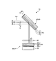
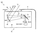
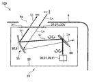
- FIG. 1 is a view for explaining an embodiment of the present invention, and is a longitudinal sectional view schematically showing a moving body and a display device.
- FIG. 2 is a diagram showing a selective reflection plate and an image forming apparatus that can be included in the display device of FIG.
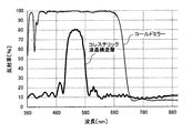
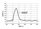
- FIG. 3 is a graph showing the reflection characteristics of the polarization selective reflection layer included in the selective reflection plate.
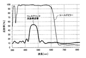
- FIG. 4 is a graph showing the reflection characteristics of the polarization selective reflection layer included in the selective reflection plate.
- FIG. 5 is a longitudinal sectional view showing a modification of the display device.
- FIG. 6 is a longitudinal sectional view showing another modification of the display device.
- FIG. 7 is a longitudinal sectional view showing still another modification of the display device.
- FIG. 1 is a view for explaining an embodiment of the present invention, and is a longitudinal sectional view schematically showing a moving body and a display device.
- FIG. 2 is a diagram showing a selective reflection plate and an image forming apparatus that can be included in the display
- FIG. 8 is a diagram for explaining a modification of the image forming apparatus.
- FIG. 9 is a diagram for explaining another modification of the image forming apparatus.
- FIG. 10 is a longitudinal sectional view showing still another modification of the display device.
- FIG. 11 is a diagram showing a selective reflection plate that can be included in the display device of FIG.
- FIG. 12 is a graph showing the reflection characteristics of the polarization selective reflection layer included in the selective reflection plate.
- FIG. 13 is a longitudinal sectional view showing still another modification of the display device.
- FIG. 14 is a diagram showing the selective reflector used in Examples 1 to 4.
- FIG. 15 is a graph showing the reflection characteristics of the selective reflection plates used in Examples 1 to 4.
- FIG. 16 is a graph showing the reflection characteristics of the selective reflection plates used in Examples 1 to 4.
- FIGS. 1 to 16 are diagrams for explaining an embodiment and its modification according to the present invention.
- FIG. 1 is a longitudinal sectional view showing the entire configuration of the display device together with a part of the moving body
- FIG. 2 is a longitudinal sectional view showing a main part of the display device.
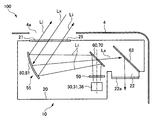
- 3 and 4 are graphs showing the reflection characteristics of the selective reflection plate included in the display device with respect to image light or the reflection characteristics of the selective reflection plate with respect to outside light.
- the moving body 1 includes a moving body main body 2 and a display device 10 mounted on the moving body main body 2.
- the mobile body 2 include a car, a ship, a railway vehicle, and an airplane.
- the mobile body 2 is an automobile.
- the display device 10 is disposed in the dashboard 4 and projects an image on the windshield 3.
- the image light projected toward the windshield 3 is reflected by the windshield 3 and can be observed by the driver of the mobile body 2. That is, the windshield 4 functions as a reflector having translucency.
- the driver visually recognizes the virtual image at a position ahead of the windshield 3 by a distance corresponding to the optical path length of the image light Li from the image forming apparatus 30 to the windshield 3 included in the display device 10. Become.
- the display device 10 is configured as a projection display device, more specifically as a head-up display.
- the windshield 4 forms the projection apparatus 100 with the display apparatus 10 as a to-be-projected body which makes the projection surface where an image light is projected.
- the dashboard 4 has an opening 4a.
- the image light Li from the display device 10 travels toward the windshield 3 through the opening 4a.
- the external light Lx that has entered the moving body 2 via the windshield 3, particularly sunlight travels in the reverse direction along the optical path of the image light Li, and enters the display device 10. Is incident on.
- the image forming apparatus 30 included in the display device 10 includes optical films having particularly low heat resistance, and the function may be impaired by receiving external light Lx.
- a device for effectively suppressing the heating of the image forming apparatus included in the display device 10 is made.
- the details of the display device 10 in the present embodiment will be described.
- the display device 10 is usually provided in the mobile body 1 without being limited to the automobile, and the driver or the driver of the mobile body 1 can check the state of the mobile body 2 through the display device. The state around the mobile body 2 can be confirmed.
- a driver or a driver of the moving body 1 is usually located in an area partitioned by transparent glass or the like, and grasps an external situation through the transparent glass. Therefore, the display device 10 mounted on the mobile body 2 tends to be installed in an environment that easily receives external light Lx, particularly sunlight.
- One embodiment described below is not limited to an automobile, and is widely useful in the display device 10 generally mounted on the mobile body 1.
- the display device 10 guides the housing 20, the image forming device 30 disposed in the housing 20, and image light formed by the image forming device 30 to the outside of the housing 20. Guiding means 55.
- the image light Li from the image forming apparatus 30 is composed of light of one linearly polarized component.
- a 1 ⁇ 4 wavelength phase difference layer 50 is provided between the image forming apparatus 30 and the guiding unit 55.
- each component will be described.
- the housing 20 is made of resin or metal. As shown in FIG. 1, an opening 21 is formed in the housing 20 at a position facing the windshield 3.
- the opening 21 is provided with a transparent cover 25 having visible light permeability.
- the transparent cover 25 can be a transparent plate made of polycarbonate resin or acrylic resin.
- the transparent cover 25 may function as an infrared reflection film that selectively reflects infrared rays (a concept including near infrared rays) for the purpose of suppressing the incidence of infrared rays into the housing 20.
- the image forming apparatus 30 is an apparatus that forms an image, and emits image light Li that forms the image. As shown in FIG. 2, a liquid crystal display device 31 can be used as the image forming apparatus 30.
- the liquid crystal display device 31 includes a liquid crystal display panel 32 and a surface light source device 33 which is disposed on the back side of the liquid crystal display panel 32 and illuminates the liquid crystal display panel 32 in a planar shape from the back side.
- the surface light source device 33 can be configured by various types of backlights such as a direct type and an edge light type.
- the liquid crystal display panel 32 functions as a shutter that controls transmission or blocking of light from the surface light source device 33 for each pixel, and can display an image on the display surface.
- the illustrated liquid crystal display panel 32 includes, in order from the surface light source device 33 side, a lower polarizing plate 32a, a liquid crystal cell 32b, and an upper polarizing plate 32c.
- the lower polarizing plate 32a and the upper polarizing plate 32c are absorption polarizers, which decompose incident light into two orthogonal polarization components (P wave and S wave), and are in one direction (a direction parallel to the transmission axis).
- P wave and S wave orthogonal polarization components
- the alignment direction of the liquid crystal molecules in the liquid crystal cell 32b changes depending on whether or not an electric field is applied.
- the polarization component in a specific direction transmitted through the lower polarizing plate 32a arranged on the light incident side rotates the polarization direction by 90 ° when passing through the liquid crystal cell 32b to which no electric field is applied, When passing through the liquid crystal cell 32b to which an electric field is applied, the polarization direction is maintained.
- liquid crystal display panel 32 liquid crystal display unit
- transmission or blocking of light from the surface light source device 33 can be controlled for each pixel.
- the details of the liquid crystal display device 31 are described in various known documents (for example, “Flat Panel Display Dictionary” (published by Tatsuo Uchida, Hiraki Uchiike), 2001, Industrial Research Council). The detailed description above is omitted.
- the image light Li emitted from the liquid crystal display device 31 becomes light of one linearly polarized light component corresponding to the transmission axis of the upper polarizing plate 32c.
- the image light Li emitted from the image forming apparatus 30 enters the quarter wavelength phase difference layer 50.
- the quarter-wave retardation layer 50 provides a quarter-wave phase difference to the transmitted light. Therefore, the image light Li composed of the light of one linearly polarized light component is converted into a right circularly polarized light component or a left circularly polarized light component by passing through the quarter wavelength retardation layer 50.
- the image light Li transmitted through the quarter-wave retardation layer 50 is converted into a right circularly polarized component.
- FIGS. 1 and 2 the image light Li transmitted through the quarter-wave retardation layer 50 is converted into a right circularly polarized component.
- the quarter-wave retardation layer 50 is disposed away from the image forming apparatus 30, but is not limited thereto.
- the quarter-wave retardation layer 50 may be fixed with respect to the image forming apparatus 30.
- the quarter-wave retardation layer 50 may be laminated on the image forming surface of the image forming apparatus 30.
- the guiding means 55 guides the image light Li from the image forming apparatus 30 toward the windshield 3. That is, the guiding unit 55 is a projection optical system (projection optical system) that projects the image light Li from the image forming apparatus 30 onto the windshield 3.
- the guiding unit 55 includes a selective reflection plate 60 and a reflection unit 80.
- the selective reflection plate 60 is configured to selectively reflect the image light Li to adjust the optical path of the image light Li, while transmitting most of the unnecessary external light Lx that has entered the display device 10.
- the selective reflection plate 60 is a member expected to have a function of dividing the optical path of the image light and the optical path of the unnecessary external light Lx. Providing the selective reflection plate 60 effectively prevents the outside light Lx from traveling to the image forming apparatus 30.
- the reflecting means 80 is not given a function of separating the image light Li and the external light Lx.
- the reflecting means 80 can be configured as a reflecting mirror, for example.
- the reflecting means 80 is configured as a concave mirror 81.
- the guiding unit 55 is not limited to the illustrated example.
- the guiding unit 55 may include an optical element such as a prism instead of the reflecting unit 80 or in addition to the reflecting unit 80.
- the selective reflection plate 60 includes a base material 61 and a polarization selective reflection layer 70 laminated on the base material 61.
- the polarization selective reflection layer 70 has a property of selectively reflecting the image light Li to change the optical path of the image light. That is, the polarization selective reflection layer 70 distinguishes the image light Li from some other light, and reflects the image light with a higher reflectance than any other light. In the illustrated example, the polarization selective reflection layer 70 reflects the image light Li with a higher reflectance than the external light Lx.
- the polarization selective reflection layer 70 has a property of selectively transmitting the external light Lx.
- the polarization selective reflection layer 70 distinguishes the external light Lx from some other light and transmits the external light Lx with a higher transmittance than any other light. In the illustrated example, the polarization selective reflection layer 70 transmits the external light Lx with a higher transmittance than the image light Li.
- the polarization selective reflection layer 70 includes a cholesteric liquid crystal structure layer having a cholesteric liquid crystal structure.
- the cholesteric liquid crystal structure layer is composed of a liquid crystalline composition exhibiting cholesteric regularity, and as a physical molecular arrangement of the liquid crystal molecules in the cholesteric liquid crystal structure, the director of the liquid crystal molecules rotates continuously in the thickness direction of the layer. It has become a spiral structure.
- the cholesteric liquid crystal structure has a polarization separation characteristic that separates a circularly polarized light component in one direction and a circularly polarized light component in the reverse direction based on the physical molecular arrangement of the liquid crystal molecules. .
- the non-polarized light incident along the spiral axis is separated into two polarized light (right circularly polarized light and left circularly polarized light), one of which is transmitted and the rest is reflected.
- This phenomenon is known as circular dichroism, and when a spiral direction in the spiral structure of liquid crystal molecules is appropriately selected, a circularly polarized component having the same optical rotation direction as this spiral direction is selectively reflected.
- ⁇ 0 nav ⁇ p (1)
- p the helical pitch length in the helical structure of the liquid crystal molecules (the length per pitch of the molecular helix of the liquid crystal molecules)
- nav the average refractive index in a plane orthogonal to the helical axis.
- the wavelength bandwidth ⁇ of the reflected light at this time is expressed by the following equation (2).
- ⁇ n is a birefringence value.
- ⁇ ⁇ n ⁇ p (2)
- the cholesteric liquid crystal structure layer has wavelength selectivity in addition to circular polarization selectivity. Therefore, the light of one circularly polarized light component (for example, right circularly polarized light in the selective reflection wavelength region) belonging to the range (selective reflection wavelength region) of the wavelength bandwidth ⁇ centered on the selective reflection central wavelength ⁇ 0 is polarized light selectively reflected.
- the light is selectively reflected by the layer 70 (reflected at a higher reflectance than other light), and the other light is selectively transmitted by the polarization selective reflection layer 70 (right circularly polarized light within the selective reflection wavelength region). It is transmitted with a higher transmittance than the component light).
- the polarization selective reflection layer 70 preferably selectively reflects light in a specific wavelength range that covers only a part of the visible light range (for example, a wavelength range of 380 nm to 780 nm). More specifically, it is preferable that the polarization selective reflection layer 70 selectively reflects only light in a wavelength range corresponding to the wavelength range of the image light Li projected from the image forming apparatus 30. In addition, when it is necessary to reflect light in a plurality of wavelength ranges, that is, when the image light Li is composed of visible light in a plurality of wavelength ranges, the polarization selective reflection layer 70 has discontinuously different helical pitches. It preferably includes at least two cholesteric liquid crystal structure layers having a length.
- the image forming apparatus 30 generally realizes color display with light in the wavelength ranges of red (R), green (G), and blue (B), which are the three primary colors of light. Therefore, for example, on the basis of the case where light is perpendicularly incident on the polarization selective reflection layer 70, light having a selective reflection center wavelength in the range of 430 to 460 nm, 540 to 570 nm, and 580 to 620 nm is selectively selected. It is preferable to determine the helical pitch length of the cholesteric liquid crystal structure for the plurality of cholesteric liquid crystal structure layers included in the polarization selective reflection layer 70 so as to reflect.
- the cholesteric liquid crystal structure of the cholesteric liquid crystal structure layer has an optical characteristic that the selective reflection wavelength region shifts to the short wavelength side (so-called “blue shift”) when light is incident obliquely. Therefore, it is preferable to appropriately adjust the helical pitch length of the cholesteric liquid crystal structure according to the incident angle of the image light Li incident on the selective reflection plate 60 from the image forming apparatus 30.
- the polarization selective reflection layer 70 includes a first cholesteric liquid crystal structure layer 71 that selectively reflects light of the right circularly polarized light component in the red (R) wavelength region, and a green (G)
- B blue
- the thickness of the cholesteric liquid crystal structure layers 71, 72, 73 is set to a size that reflects approximately 100% of the light of a specific circularly polarized component that is selectively reflected (a size that allows the reflectance to be saturated). It is preferable.
- the reflectivity of the cholesteric liquid crystal structure layer depends directly on the number of helical pitches, but indirectly depends on the thickness of the cholesteric liquid crystal structure layer if the helical pitch length is fixed. Specifically, since it is said that about 4 to 8 pitches are necessary to obtain 100% reflectivity, a material for forming a cholesteric liquid crystal structure layer (for example, a liquid crystalline composition exhibiting cholesteric regularity).
- a single layer of cholesteric liquid crystal structure layer that reflects light in one of the red (R), green (G), and blue (B) wavelength ranges It preferably has a thickness of about 1 to 10 ⁇ m.
- the thickness of the cholesteric liquid crystal structure layer is not as good as it is thick. If it is too thick, it becomes difficult to control the orientation, unevenness, and the degree of light absorption by the material itself. The range described above is appropriate because it increases.
- the first cholesteric liquid crystal structure layer 71 reflects non-polarized light in the wavelength region of 600 nm to 700 nm with a reflectance of 30% or more
- the second cholesteric liquid crystal structure layer 72 is 450 nm to 550 nm.
- the third cholesteric liquid crystal structure layer 73 reflects non-polarized light in the wavelength region of 300 nm to 400 nm with a reflectance of 30% or more. You may do it.
- image light Li is emitted from the image forming apparatus 30.
- the image forming apparatus 30 is a liquid crystal display device 31. Therefore, the image light Li is composed of light of a linearly polarized light component corresponding to the direction of the transmission axis of the upper polarizing plate 32 c of the liquid crystal display device 31.
- the image light Li emitted from the image forming apparatus 30 then passes through the 1 ⁇ 4 wavelength phase difference layer 50.
- the 1 ⁇ 4 wavelength phase difference layer 50 provides phase modulation for 1 ⁇ 4 wavelength to the image light Li.
- the polarization state of the image light Li is converted from one linearly polarized light to one circularly polarized light, for example, right circularly polarized light.
- the image light Li transmitted through the 1 ⁇ 4 wavelength phase difference layer 50 is directed to the selective reflection plate 60.
- the selective reflector 60 includes a first cholesteric liquid crystal structure layer 71, a second cholesteric liquid crystal structure layer 72, and a third cholesteric liquid crystal structure layer 73.
- the cholesteric liquid crystal structure layer is a layer having a cholesteric liquid crystal structure, has wavelength selectivity and circular polarization selectivity, and can selectively reflect the image light Li.
- the image light Li reflected by the selective reflection plate 60 is then magnified and reflected by the reflecting means 80.
- the image light Li magnified and reflected by the reflecting means 80 passes through the transparent cover 25 and is emitted from the display device 10.
- the image light Li is then reflected by the windshield 3 and is observed by the driver and the operator who are observers.
- the graph of FIG. 3 shows an example of the reflection characteristic of the cholesteric liquid crystal structure layer in which the selective reflection center wavelength is set to 550 nm.
- the reflection characteristics shown in FIG. 3 are based on the assumption that the image light Li is incident from the liquid crystal display device 31, and the light incident on the cholesteric liquid crystal structure layer is set to the light of the right circularly polarized light component. (V-670). From the results shown in FIG. 3, it is understood that the image light Li having the selective reflection center wavelength can be reflected with a high reflectance of about 80%. Therefore, according to the display device 10 that reflects and guides the image light Li by the cholesteric liquid crystal structure layer, it is possible to display the image brightly by using the image light Li from the image forming device 30 with high efficiency. .
- the image light finally observed is composed of one circularly polarized component. Therefore, an image can be observed even by an observer wearing polarized sunglasses.
- the external light Lx is incident on the display device 10 through the opening 21 of the housing 20 (through the transparent cover 25 in the illustrated example).
- the external light Lx travels in the reverse direction of the optical path of the image light Li and enters the image forming apparatus 30 including an optical film with low heat resistance (for example, the upper polarizing plate 32c).
- a concave mirror 81, a lens, or the like may be provided in the display device 10 for the purpose of enlarging the image light Li.
- the external light Lx may be collected by an optical element such as a concave mirror 81 or a lens, and this problem becomes more prominent.
- Patent Document 1 JP2015-155948A proposes covering the image forming apparatus with a reflective layer including a layer in which a cholesteric liquid crystal layer is fixed. That is, in Patent Document 1, the polarization selectivity and the wavelength selectivity of the cholesteric liquid crystal layer are used to transmit image light, while the light having a wavelength region different from that of the image light and the circular polarization component different from that of the image light. Reflects light. Therefore, most of the external light is reflected by the reflective layer and blocked from entering the image forming apparatus.
- the configuration proposed in Patent Document 1 may have a certain effect in preventing the temperature rise of the image forming apparatus due to external light irradiation. However, due to this solution, the housing of the display device is not effective. Another problem was that external light diffused in the body. More specifically, there arises a problem that the contrast of an image is lowered due to diffusion of external light.
- the polarization selective reflection layer 70 selectively reflects the image light Li, and light in a wavelength region different from that of the image light Li and a circularly polarized component different from that of the image light Li.
- the graph of FIG. 4 shows an example of the reflection characteristic of the cholesteric liquid crystal structure layer in which the selective reflection center wavelength is set to 550 nm.
- the reflection characteristics shown in FIG. 4 were measured using the same measuring device as the reflection characteristics shown in FIG. 3 with the incident light as non-polarized light, assuming the incidence of external light Lx. As shown in FIG.
- the cholesteric liquid crystal structure layer reflects about 50% of the external light Lx having a selective reflection center wavelength, but its wavelength selectivity is very sharp, and the reflectance of light deviated by about 30 nm from the selective reflection center wavelength. Decreases to about 30%, and the reflectance of light deviated by about 45 nm from the selective reflection center wavelength decreases to about 15%. Therefore, only a small amount of the external light Lx is reflected by the selective reflection plate 60. In other words, according to the present embodiment, it is possible to effectively cope with a problem that the image forming apparatus 30 is damaged by heating due to external light irradiation.
- the image forming apparatus 30 is not disposed at a position facing the polarization selective reflection layer 70 along the incident direction of the external light Lx to the polarization selective reflection layer 70.
- the image forming apparatus 30 is not disposed at a position facing the polarization selective reflection layer 70. That is, in Patent Document 1, the image forming apparatus 30 is shielded from heat by blocking the external light Lx by the cholesteric liquid crystal layer, whereas in the present embodiment, the image forming apparatus is used by using the cholesteric liquid crystal structure layer.
- the arrangement of retracting 30 from the external light Lx is made possible, thereby realizing heat avoidance. For this reason, in this Embodiment, it is not necessary to reflect the external light Lx, and the contrast fall resulting from reflection of the external light Lx can be avoided effectively.
- the selective reflection plate 60 includes a base material 61 and three cholesteric liquid crystal structure layers 71, 72, and 73 stacked on the base material 61. It is preferable to have the absorption layer 62 laminated
- the absorption layer 62 functions as a beam stopper and can collect the external light Lx without diffusing in the housing 20. Thereby, it is possible to extremely effectively prevent a decrease in contrast due to the diffusion of external light.
- the absorption layer 62 the member which can absorb visible light and infrared rays (concept including near infrared rays) can be used, without being specifically limited.
- a black light-absorbing rubber material or an inorganic oxide for example, black anodized aluminum
- a radiation fin in the absorption layer 62 or to provide cooling means such as a blower fan.
- the external light Lx that has passed through the selective reflection plate 60 is guided separately from the guiding means 55 for guiding the image light Li.
- External light guiding means 63 is provided.
- the external light guiding means 63 may include various elements that guide light, for example, a lens, a prism, a reflecting mirror, and the like.
- the external light guiding means 63 is composed of a reflecting mirror that bends the optical path of the external light Lx.
- the external light guiding means 63 guides the external light Lx to the outside of the housing 20 through the discharge opening 22 provided in the housing 20.
- the present invention is not limited to this example, and the external light Lx may be guided to a heat radiating fin provided for cooling the image forming apparatus 30 or a cooling system installed in the movable body 2.
- the discharge opening 22 is covered with a visible light transmissive lid member 22a.
- the lid member 22a can transmit the external light Lx and prevents dust and the like from entering the housing 20.
- the wavelength selection system of the cholesteric liquid crystal layer is sharp and the selective reflection wavelength range is narrow.
- the range of the wavelength range of the image light Li is narrower than the range of the wavelength range of the external light Lx excluding the wavelength range of the image light Li, that is, the range of the wavelength range to be selectively transmitted. Therefore, as proposed in Patent Document 1 (JP2015-155948A), a large number of cholesteric liquid crystal layers having different selective reflection center wavelengths are stacked in order to reflect visible light and infrared light having a wavelength range different from that of image light. Need arises. That is, with the configuration proposed in Patent Document 1, problems such as multilayered, complicated, and expensive cholesteric liquid crystal layers may occur.
- the polarization selective reflection layer 70 of the selective reflection plate 60 may selectively reflect the image light Li.
- the wavelength range of the image light Li is limited, and the wavelength range is also narrow. Therefore, the polarization selective reflection layer 70 does not need to include a large number of cholesteric liquid crystal structure layers.
- the reflection characteristics of the cold mirror in FIG. 3 are measured values when the incident light is one circularly polarized light
- the reflection characteristics of the cold mirror in FIG. 4 are measured values when the incident light is non-polarized light.
- the cold mirror is a member that selectively transmits visible light while transmitting infrared rays (a concept including near infrared rays). Therefore, in the display device using the cold mirror instead of the polarization selective reflection layer 70 in the present embodiment, the image light Li emitted from the image forming device 30 is reflected by the cold mirror, but the infrared light is transmitted through the cold mirror. Incident to the image forming apparatus 30 is restricted.
- the display device 10 mounted on the moving body 1 includes the image forming apparatus 30 that emits the image light Li, and guiding means that guides the image light Li (projection optical system, Projection optical system) 55.
- the guiding means 55 includes a polarization selective reflection layer 70 including one or more layers having a cholesteric liquid crystal structure.
- the polarization selective reflection layer 70 reflects the image light Li and changes the optical path of the image light Li.
- the polarization selective reflection layer 70 reflects the image light Li, while transmitting light having a circularly polarized component different from that of the image light Li and light having a wavelength region different from that of the image light Li. Can do. Since the selective reflection wavelength region of the cholesteric liquid crystal structure layer forming the polarization selective reflection layer 70 is relatively narrow, infrared light (a concept including near infrared rays) and visible light having a wavelength region different from the image light Li can be used. Most of the external light Lx incident on the display device 10 so as to travel in the reverse direction of the optical path is transmitted through the polarization selective reflection layer 70. Thereby, it is possible to effectively avoid a large amount of external light Lx entering the image forming apparatus 30. In addition, the image forming apparatus 30 can be effectively prevented from being damaged by being heated by external light.
- unnecessary light incident on the display device 10 is deflected from the image forming device 30 by transmitting the polarization selective reflection layer 70 instead of reflection. Therefore, unnecessary light can be effectively prevented from being emitted from the display device 10 along the same optical path as the image light Li. Then, it is possible to effectively avoid image deterioration due to a decrease in contrast due to this unnecessary light. Furthermore, much of the unnecessary light deflected from the image forming apparatus 30 can be collected after passing through the polarization selective reflection layer 70. Thereby, it is possible to more effectively prevent image degradation caused by the external light Lx incident on the display device 10.
- the polarization selective reflection layer 70 when the polarization selective reflection layer 70 is manufactured, only a cholesteric liquid crystal structure layer having a selective reflection wavelength region in the wavelength region of the image light Li in the visible light wavelength region may be prepared. Even in the full-color display device 10, the wavelength range of the image light Li is limited. Therefore, the polarization selective reflection layer 70 does not need to include a large number of cholesteric liquid crystal structure layers. Typically, it is sufficient to include a single cholesteric liquid crystal structure layer in the display device 10 for monochromatic display, and a color display of color display is possible.
- the display device 10 includes a cholesteric liquid crystal structure layer of a selective reflection wavelength region including at least three of red, green, and blue which are three primary colors of light having different selective reflection wavelength regions, and at most including a light source wavelength band of the image forming device It is enough. Therefore, it is possible to effectively prevent the polarization selective reflection layer from becoming multi-layered, complicated and expensive.
- the display device 10 is suitable for the moving body 1 that is an environment in which external light is easily incident.
- the display device 10 includes the 1 ⁇ 4 wavelength phase difference layer 50 arranged at a position on the optical path of the image light Li from the image layer forming device 30 to the polarization selective reflection layer 70.
- the image light Li emitted from the image forming apparatus 30 is light of one linearly polarized component
- the image forming apparatus 30 is a liquid crystal display device 31, a laser projector, or the like, up to the polarization selective reflection layer 70.
- the quarter-wave retardation layer 50 disposed on the optical path can convert the image light Li into light of a circularly polarized component that is selectively reflected by the polarization selective reflection layer 70. Therefore, the above-described excellent operational effects can be enjoyed while appropriately selecting the image forming apparatus 30.
- the image forming apparatus 30 emits image light Li composed of light of one linearly polarized light component.
- the image light Li composed of one linearly polarized light component can be converted into a circularly polarized light component by using the quarter wavelength phase difference layer 50. Therefore, the image light Li emitted from the image forming apparatus 30 can be used with high utilization efficiency.
- the display device 10 further includes a quarter wavelength retardation layer 51 arranged at a position on the optical path of the image light reflected by the polarization selective reflection layer 70. Also good.
- the image light Li reflected by the polarization selective reflection layer 70 can be converted from a circularly polarized light component to a linearly polarized light component.
- Various optical applications can be easily applied to the linearly polarized image light Li.
- the display device 10 further includes a polarizer 27 disposed on the optical path of the image light Li after being reflected by the polarization selective reflection layer 70 and transmitted through the 1 ⁇ 4 wavelength phase difference layer 51. You may make it have.
- the polarizer 27 may be either an absorption polarizer 27a or a reflection polarizer 27b.
- an absorption polarizer 27 a or a reflection polarizer 27 b is installed in the opening 21 of the housing 20 instead of the transparent cover 25 in the above-described embodiment.
- the absorption polarizer 27a decomposes incident light into two orthogonal polarization components (P wave and S wave) and vibrates in one direction (direction parallel to the transmission axis) (for example, P wave) ) And absorbs a linearly polarized light component (for example, S wave) that vibrates in the other direction (direction parallel to the absorption axis) perpendicular to the one direction.
- P wave and S wave orthogonal polarization components
- S wave linearly polarized light component
- the reflective polarizer 27b decomposes incident light into two orthogonal polarization components (P wave and S wave) and vibrates in one direction (direction parallel to the transmission axis) (for example, P wave) is transmitted, and a linearly polarized component (for example, S wave) that vibrates in the other direction (direction parallel to the absorption axis) orthogonal to the one direction is reflected.
- P wave and S wave orthogonal polarization components
- the image light Li is converted from a circularly polarized light component to a linearly polarized light component by passing through the 1 ⁇ 4 wavelength phase difference layer 51.
- the absorption polarizer 27a or the reflection polarizer 27b is arranged so that the linearly polarized light component of the image light Li can be transmitted, the utilization efficiency of the image light Li does not decrease.
- the image light Li can be used more effectively when the image light Li is linearly polarized light (for example, S wave) than when it is circularly polarized light, and the reflectance at the windshield 3 is high. .
- it is effective to provide a 1 ⁇ 4 wavelength phase difference layer on the optical path of the image light Li reflected by the polarization selective reflection layer 70.
- an infrared reflecting film may be laminated on the polarizer 27.
- the display device 10 is placed on the optical path of the image light Li from the image layer forming device 30 to the polarization selective reflection layer 70 in place of the quarter-wave retardation layer 50 described above and is polarized. You may make it further have the quarter wavelength phase difference layer 52 arrange
- the image light Li emitted from the image forming apparatus 30 is light of one linearly polarized component
- the image forming apparatus 30 is a liquid crystal display device 31, a laser projector, or the like
- the quarter-wave retardation layer 52 disposed on the optical path to the polarization selective reflection layer 70 converts the image light Li into light having a circular polarization component that is selectively reflected by the polarization selective reflection layer 70. be able to.
- the image light Li reflected by the polarization selective reflection layer 70 can be reconverted into a linearly polarized light component by the same quarter-wave retardation layer 52.
- the polarization state of the image light Li after the optical path is adjusted by the polarization selective reflection layer 70 can be converted into a linearly polarized light component.
- Various optical applications can be easily applied to the linearly polarized image light Li.
- the quarter-wave retardation layer 52 is laminated on the polarization selective reflection layer 70.
- the image light Li is 1/4 when incident on the polarization selective reflection layer 70 and twice after being reflected by the polarization selective reflection layer 70.
- the wavelength retardation layer 52 can be transmitted more reliably. Since the quarter wavelength retardation layer 52 can be disposed close to the polarization selective reflection layer 70, the display device 10 can be reduced in size.
- the image after the display device 10 is reflected by the polarization selective reflection layer 70 and is transmitted through the 1 ⁇ 4 wavelength phase difference layer 52.
- the liquid crystal display device 31 is exemplified as the image forming device 30 that emits the image light Li composed of one linearly polarized component, but is not limited to this example.
- the laser projector 36 can be used as an image forming apparatus 30 that emits image light Li composed of one linearly polarized component.
- the laser projector 36 shown in FIG. 8 includes a laser light source 37 that emits laser light, a scanning device 38 that changes the optical path of the laser light with time, and a screen on which the laser light whose optical path has been adjusted by the scanning device is incident. 39.
- the scanning device 38 adjusts the optical path of the laser beam so that the laser beam scans on the screen.
- An image is formed on the laser light source 37 by dividing the screen into pixel areas and controlling the emission and stop of the laser light from the laser light source 37 for each pixel area.
- the laser projector 36 emits the image light Li composed of one linearly polarized component from the scanning device 38. Can do.
- the laser projector 36 shown in FIG. 8 is advantageous in that the use efficiency of the light source light becomes very high as compared with the liquid crystal display device.
- the present invention is not limited thereto. It is also possible to use an image forming apparatus that emits non-polarized image light Li.
- image forming apparatus that emits non-polarized image light Li.
- non-polarized image light Li is incident on the polarization selective reflection layer 70, approximately half of the image light Li is reflected by the polarization selective reflection layer 70. That is, although the use efficiency of the image light Li is reduced, it is possible to enjoy the above-described effects such that the contrast reduction of the image due to external light reflection can be effectively prevented.
- the image forming apparatus 41 using the digital micromirror device 44 as shown in FIG. 9 also emits non-polarized image light Li unless special means are used.
- the image forming apparatus 41 illustrated in FIG. 9 includes a light source 42 that emits non-polarized light, a prism 43, and a digital micromirror device 44.
- the light source 42 includes, for example, a light emitting diode, and irradiates the prism 43 with non-polarized planar light.
- the planar light passes through the prism 43 and enters the digital micromirror device 44.
- the digital micromirror device 44 is a MEMS element including a large number of micromirrors, and functions as a reflective spatial light modulator.
- the digital micromirror device 44 forms an image by switching the reflection direction of the micromirror for each pixel.
- the image light Li formed by the digital micromirror device 44 is totally reflected by the prism 43 and travels toward the selective reflection plate 60 of the guiding means 55.
- the image forming apparatus 41 shown in FIG. 9 is advantageous in that the use efficiency of the light source light becomes very high as compared with the liquid crystal display device. Even if only about half of the image light Li can be reflected by the polarization selective reflection layer 70, the utilization efficiency of the light source light is increased as a whole.
- the image forming apparatus 30 that emits non-polarized image light Li is used, and the polarization selective reflection layer 70 includes a cholesteric liquid crystal structure layer that selectively reflects right circularly polarized light, and the left A cholesteric liquid crystal structure layer that selectively reflects light of a circularly polarized component may be included.
- the non-polarized image light Li in the selective reflection wavelength region of the cholesteric liquid crystal structure layer can be reflected by the polarization selective reflection layer 70 with high reflectance, and the light source light is used efficiently.
- the energy efficiency of the entire display device 10 can be greatly improved.
- the cholesteric liquid crystal structure layer that selectively reflects the light of the right circularly polarized light component and the cholesteric liquid crystal structure layer that selectively reflects the light of the left circularly polarized light component are opposite to each other in the spiral direction of the liquid crystal molecules.
- the cholesteric liquid crystal structure layer that selectively reflects the light of the right circularly polarized light component and the cholesteric liquid crystal structure layer that selectively reflects the light of the left circularly polarized light component have the same selective reflection center wavelength by making the pitch of the spiral structure the same. Will have.
- the polarization selective reflection layer 70 has first to sixth cholesteric liquid crystal structure layers 71 to 76.
- the first to third cholesteric liquid crystal structure layers 71, 72, and 73 selectively reflect light of the right circularly polarized component
- the fourth to sixth cholesteric liquid crystal structure layers 74, 75, and 76 have the left circularly polarized component.
- the first cholesteric liquid crystal structure layer 71 and the fourth cholesteric liquid crystal structure layer 74 have the same selective reflection center wavelength, and selectively reflect light in the red (R) wavelength region.
- the second cholesteric liquid crystal structure layer 72 and the fifth cholesteric liquid crystal structure layer 75 have the same selective reflection center wavelength, and selectively reflect light in the green (G) wavelength region.
- the third cholesteric liquid crystal structure layer 73 and the sixth cholesteric liquid crystal structure layer 76 have the same selective reflection center wavelength, and selectively reflect light in the blue (B) wavelength region.
- the graph of FIG. 12 shows an example of the reflection characteristic of the polarization selective reflection layer formed by superposing two cholesteric liquid crystal structure layers having a selective reflection center wavelength set at 550 nm.
- the winding directions of the spiral structure formed by the liquid crystal molecules are opposite to each other.
- the reflection characteristics shown in FIG. 12 were measured using the same measuring device as the reflection characteristics shown in FIG.
- the polarization selective reflection layer can reflect image light having a selective reflection center wavelength with a high reflectance of nearly 80%, and the wavelength selectivity is sharp. Therefore, even in an example using non-polarized image light, it is possible to effectively cope with the problem that the image forming apparatus 30 is heated and damaged by external light irradiation while the image is displayed brightly with high trust.
- the display device 10 may further include a polarizer 27 disposed on the optical path of the image light Li after being reflected by the polarization selective reflection layer 70.
- the polarizer 27 may be either an absorption polarizer 27a or a reflection polarizer 27b.
- an absorption polarizer 27a or a reflection polarizer 27b is installed in the opening 21 of the housing 20. .
- Display devices 10 (Examples 1 to 4 and Comparative Examples 1 to 4) that function as a head-up display for vehicles were produced.
- This display device has the configuration shown in FIG. Specifically, the display device 10 is stacked on the liquid crystal display device 31 (image layer forming device 30), the selective reflection plate 60 and the concave mirror 81 (reflection means 80) that reflect image light, and the selective reflection plate 60. And a quarter-wave retardation layer 52.
- the display device (Examples 1 to 4 and Comparative Examples 1 to 4) includes a housing 20 in which an opening 21 is formed, and a transparent cover 25 provided so as to cover the opening 21. , To have.
- the selective reflector 60 and the transparent cover 25 were changed between Examples 1 to 4 and Comparative Examples 1 to 4.
- the selective reflector 60 having the configuration shown in FIG. 14 was used.
- the selective reflection plate 60 used in Examples 1 to 4 includes five cholesteric liquid crystal structure layers that reflect one polarization component. The selected center wavelengths reflected by the five cholesteric liquid crystal structure layers were made different from each other. The colors of reflected light of the five cholesteric liquid crystal structure layers were dark red, red, green, light blue, and blue, respectively.
- the graph of FIG. 15 shows the reflection characteristics of the selective reflection plate 60 used in Examples 1 to 4 when one linearly polarized light (S wave) is incident at an incident angle of 30 °.
- the graph of FIG. 16 shows the reflection characteristics of the selective reflection plate 60 used in Examples 1 to 4 when non-polarized light is incident at an incident angle of 30 °.
- image light composed of one linearly polarized light component in the visible light region can be reflected with high efficiency.
- non-polarized external light in the visible light region can be transmitted almost half without being reflected.
- Comparative Examples 1 to 4 a cold mirror was used as the selective reflection plate 60.
- the cold mirror used in Comparative Examples 1 to 4 had the reflection characteristics of the cold mirror shown in FIG.
- Example 1 and Comparative Example 1 a transparent polycarbonate plate was used as a transparent cover.
- Example 2 and Comparative Example 2 an absorbing polarizer (PVA-iodine type) was used as a transparent cover.
- Example 3 and Comparative Example 3 a dielectric multilayer type reflective polarizer (“DBEF” manufactured by 3M) was used as a transparent cover.
- Example 4 and Comparative Example 4 a wire grid type reflective polarizer (model number HTN manufactured by Asahi Kasei Co., Ltd.) was used as a transparent cover.
- the configuration of the display device other than the selective reflection plate 60 and the transparent cover 25 was made common between Examples 1 to 4 and Comparative Examples 1 to 4.
- the liquid crystal display device 31, the concave mirror 81, and the housing 20 used the configurations of commercially available head-up displays for vehicles.
- the image light of the liquid crystal display device 31 was one linearly polarized light.
- the quarter-wave retardation layer laminated on the selective reflection plate converted one linearly polarized light emitted from the liquid crystal display device 31 into a circularly polarized light component that can be reflected by the selective reflection plate.
- the quarter-wave retardation layer laminated on the selective reflection plate transmits circularly polarized image light reflected by the selective reflection plate through the polarizer used in Examples 2 to 4 and Modifications 2 to 4. Converted to the linear polarization obtained.
- Table 1 shows the temperature measurement results.
- Examples 1 to 4 using a cholesteric liquid crystal structure layer as a selective reflection plate use any transparent cover as compared with Comparative Examples 1 to 4 using a cold mirror as a selective reflection plate. In this case, the temperature rise on the display surface of the liquid crystal display device could be greatly reduced. In particular, the temperature increase in Example 1 in which no polarizer was used was lower than that in Comparative Examples 2 to 4 using a polarizer that could absorb or reflect part of the light from the xenon lamp.
- Example 2 Brightness measurement> As shown in FIG. 7, the display device was installed in the vicinity of the transparent glass so that the display image was reflected on the transparent glass (the windshield 3 in FIG. 7). With the display device displaying a certain image, the luminance in the direction in which the image was observed was measured on transparent glass. The measured brightness is shown in Table 1. The luminance in Examples 1 to 4 was slightly lower than that in Comparative Examples 1 to 4, but the display images in Examples 1 to 4 could be observed with sufficient brightness that would not be a practical problem.
Abstract
Un dispositif d'affichage (10) comporte un dispositif de formation d'image (30) pour émettre une lumière d'image (Li), et un moyen de guidage (55) pour guider la lumière d'image Li. Le moyen de guidage comprend une couche de réflexion de sélection de polarisation (70) comprenant une ou plusieurs couches qui ont une structure de cristaux liquides cholestériques. La couche de réflexion de sélection de polarisation réfléchit la lumière d'image pour changer le trajet optique de la lumière d'image.
Priority Applications (1)
| Application Number | Priority Date | Filing Date | Title |
|---|---|---|---|
| JP2018565580A JPWO2018143231A1 (ja) | 2017-01-31 | 2018-01-31 | 表示装置、投射装置および移動体 |
Applications Claiming Priority (2)
| Application Number | Priority Date | Filing Date | Title |
|---|---|---|---|
| JP2017015980 | 2017-01-31 | ||
| JP2017-015980 | 2017-01-31 |
Publications (1)
| Publication Number | Publication Date |
|---|---|
| WO2018143231A1 true WO2018143231A1 (fr) | 2018-08-09 |
Family
ID=63039769
Family Applications (1)
| Application Number | Title | Priority Date | Filing Date |
|---|---|---|---|
| PCT/JP2018/003090 WO2018143231A1 (fr) | 2017-01-31 | 2018-01-31 | Dispositif d'affichage, dispositif de projection et corps mobile |
Country Status (2)
| Country | Link |
|---|---|
| JP (1) | JPWO2018143231A1 (fr) |
| WO (1) | WO2018143231A1 (fr) |
Citations (10)
| Publication number | Priority date | Publication date | Assignee | Title |
|---|---|---|---|---|
| JPS61238015A (ja) * | 1985-04-15 | 1986-10-23 | Nissan Motor Co Ltd | 車両用表示装置 |
| JP2008070782A (ja) * | 2006-09-15 | 2008-03-27 | Seiko Epson Corp | ヘッドアップディスプレイ |
| WO2013190958A1 (fr) * | 2012-06-22 | 2013-12-27 | 旭硝子株式会社 | Affichage tête haute |
| JP2014044244A (ja) * | 2012-08-24 | 2014-03-13 | Asahi Kasei E-Materials Corp | 映像表示装置 |
| JP2014191321A (ja) * | 2013-03-28 | 2014-10-06 | Denso Corp | ヘッドアップディスプレイ装置 |
| US20140307176A1 (en) * | 2013-04-12 | 2014-10-16 | Bayerische Motoren Werke Aktiengesellschaft | Light-Transmitting Pane for Displaying an Image of a Head-Up Display for Polarized Sunglasses |
| WO2015125247A1 (fr) * | 2014-02-20 | 2015-08-27 | パイオニア株式会社 | Dispositif de projection |
| WO2015166872A1 (fr) * | 2014-04-30 | 2015-11-05 | シャープ株式会社 | Dispositif d'affichage du type a projection par reflexion |
| WO2016056617A1 (fr) * | 2014-10-10 | 2016-04-14 | 日本化薬株式会社 | Film réfléchissant la lumière et film régulant la lumière, film optique, verre fonctionnel et affichage tête haute faisant appel au film réfléchissant la lumière |
| WO2016194327A1 (fr) * | 2015-05-29 | 2016-12-08 | 富士フイルム株式会社 | Élément d'affichage d'image par projection et système de projection |
Family Cites Families (2)
| Publication number | Priority date | Publication date | Assignee | Title |
|---|---|---|---|---|
| JP2006208786A (ja) * | 2005-01-28 | 2006-08-10 | Dainippon Printing Co Ltd | 反射素子及びそれを備えた投影システム |
| JP6451523B2 (ja) * | 2015-06-17 | 2019-01-16 | 株式会社デンソー | ヘッドアップディスプレイ装置 |
-
2018
- 2018-01-31 WO PCT/JP2018/003090 patent/WO2018143231A1/fr active Application Filing
- 2018-01-31 JP JP2018565580A patent/JPWO2018143231A1/ja active Pending
Patent Citations (10)
| Publication number | Priority date | Publication date | Assignee | Title |
|---|---|---|---|---|
| JPS61238015A (ja) * | 1985-04-15 | 1986-10-23 | Nissan Motor Co Ltd | 車両用表示装置 |
| JP2008070782A (ja) * | 2006-09-15 | 2008-03-27 | Seiko Epson Corp | ヘッドアップディスプレイ |
| WO2013190958A1 (fr) * | 2012-06-22 | 2013-12-27 | 旭硝子株式会社 | Affichage tête haute |
| JP2014044244A (ja) * | 2012-08-24 | 2014-03-13 | Asahi Kasei E-Materials Corp | 映像表示装置 |
| JP2014191321A (ja) * | 2013-03-28 | 2014-10-06 | Denso Corp | ヘッドアップディスプレイ装置 |
| US20140307176A1 (en) * | 2013-04-12 | 2014-10-16 | Bayerische Motoren Werke Aktiengesellschaft | Light-Transmitting Pane for Displaying an Image of a Head-Up Display for Polarized Sunglasses |
| WO2015125247A1 (fr) * | 2014-02-20 | 2015-08-27 | パイオニア株式会社 | Dispositif de projection |
| WO2015166872A1 (fr) * | 2014-04-30 | 2015-11-05 | シャープ株式会社 | Dispositif d'affichage du type a projection par reflexion |
| WO2016056617A1 (fr) * | 2014-10-10 | 2016-04-14 | 日本化薬株式会社 | Film réfléchissant la lumière et film régulant la lumière, film optique, verre fonctionnel et affichage tête haute faisant appel au film réfléchissant la lumière |
| WO2016194327A1 (fr) * | 2015-05-29 | 2016-12-08 | 富士フイルム株式会社 | Élément d'affichage d'image par projection et système de projection |
Also Published As
| Publication number | Publication date |
|---|---|
| JPWO2018143231A1 (ja) | 2019-11-14 |
Similar Documents
| Publication | Publication Date | Title |
|---|---|---|
| JP6572856B2 (ja) | ヘッドアップディスプレイ装置 | |
| JP6455339B2 (ja) | ヘッドアップディスプレイ装置 | |
| CN109416471B (zh) | 平视显示装置 | |
| JP6432540B2 (ja) | ヘッドアップディスプレイ装置 | |
| WO2016157815A1 (fr) | Dispositif d'affichage tête haute | |
| JP6459921B2 (ja) | ヘッドアップディスプレイ装置 | |
| JP6369451B2 (ja) | ヘッドアップディスプレイ装置 | |
| US10670863B2 (en) | Head-up display device with reflective optical system for vehicle | |
| CN213987029U (zh) | 双层成像抬头显示装置、抬头显示系统及交通设备 | |
| JP6036482B2 (ja) | 画像表示装置 | |
| CN110770635A (zh) | 平视显示装置 | |
| CN114077053A (zh) | 双层成像抬头显示装置、抬头显示系统及交通设备 | |
| JP7059654B2 (ja) | 表示装置、移動体、照明装置および反射板 | |
| JP6946925B2 (ja) | 虚像表示装置 | |
| JP6988353B2 (ja) | 反射体、表示装置および移動体 | |
| WO2018143231A1 (fr) | Dispositif d'affichage, dispositif de projection et corps mobile | |
| JP6620706B2 (ja) | ヘッドアップディスプレイ装置 | |
| WO2017188277A1 (fr) | Appareil d'affichage et affichage tête haute pour véhicule | |
| CN213338211U (zh) | 抬头显示设备、抬头显示系统和交通设备 | |
| CN114063288A (zh) | 抬头显示设备、抬头显示系统和交通设备 |
Legal Events
| Date | Code | Title | Description |
|---|---|---|---|
| 121 | Ep: the epo has been informed by wipo that ep was designated in this application |
Ref document number: 18748055 Country of ref document: EP Kind code of ref document: A1 |
|
| ENP | Entry into the national phase |
Ref document number: 2018565580 Country of ref document: JP Kind code of ref document: A |
|
| NENP | Non-entry into the national phase |
Ref country code: DE |
|
| 122 | Ep: pct application non-entry in european phase |
Ref document number: 18748055 Country of ref document: EP Kind code of ref document: A1 |