WO2018139845A2 - 셀타입 가스인증표준물질 제조방법, 제조장치 및 용기 - Google Patents
셀타입 가스인증표준물질 제조방법, 제조장치 및 용기 Download PDFInfo
- Publication number
- WO2018139845A2 WO2018139845A2 PCT/KR2018/001045 KR2018001045W WO2018139845A2 WO 2018139845 A2 WO2018139845 A2 WO 2018139845A2 KR 2018001045 W KR2018001045 W KR 2018001045W WO 2018139845 A2 WO2018139845 A2 WO 2018139845A2
- Authority
- WO
- WIPO (PCT)
- Prior art keywords
- container
- gas
- cell
- weight
- type gas
- Prior art date
- Legal status (The legal status is an assumption and is not a legal conclusion. Google has not performed a legal analysis and makes no representation as to the accuracy of the status listed.)
- Ceased
Links
Images



Classifications
-
- G—PHYSICS
- G01—MEASURING; TESTING
- G01N—INVESTIGATING OR ANALYSING MATERIALS BY DETERMINING THEIR CHEMICAL OR PHYSICAL PROPERTIES
- G01N1/00—Sampling; Preparing specimens for investigation
- G01N1/28—Preparing specimens for investigation including physical details of (bio-)chemical methods covered elsewhere, e.g. G01N33/50, C12Q
-
- G—PHYSICS
- G01—MEASURING; TESTING
- G01N—INVESTIGATING OR ANALYSING MATERIALS BY DETERMINING THEIR CHEMICAL OR PHYSICAL PROPERTIES
- G01N21/00—Investigating or analysing materials by the use of optical means, i.e. using sub-millimetre waves, infrared, visible or ultraviolet light
- G01N21/17—Systems in which incident light is modified in accordance with the properties of the material investigated
- G01N21/25—Colour; Spectral properties, i.e. comparison of effect of material on the light at two or more different wavelengths or wavelength bands
- G01N21/31—Investigating relative effect of material at wavelengths characteristic of specific elements or molecules, e.g. atomic absorption spectrometry
-
- G—PHYSICS
- G01—MEASURING; TESTING
- G01N—INVESTIGATING OR ANALYSING MATERIALS BY DETERMINING THEIR CHEMICAL OR PHYSICAL PROPERTIES
- G01N33/00—Investigating or analysing materials by specific methods not covered by groups G01N1/00 - G01N31/00
-
- G—PHYSICS
- G02—OPTICS
- G02B—OPTICAL ELEMENTS, SYSTEMS OR APPARATUS
- G02B27/00—Optical systems or apparatus not provided for by any of the groups G02B1/00 - G02B26/00, G02B30/00
- G02B27/10—Beam splitting or combining systems
- G02B27/14—Beam splitting or combining systems operating by reflection only
Definitions
- the present invention relates to a method for manufacturing a cell type gas certified standard material, a manufacturing apparatus, and a container, and more particularly, in the manufacture of cell type gas certified standard material, even when a toxic or highly reactive gas is injected safely.
- the present invention relates to a method for manufacturing a cell type gas certified reference material, a manufacturing apparatus, and a container, which are capable of minimizing uncertainty in measurement and analysis.
- Reference material refers to a substance that can be a standard as a chemical species in the same way as the base group in the metrology form, and in most cases refers to a pure substance. Standards are the basis for the analysis, investigation, and testing of materials, and these standards are essential, especially for analyzes and tests that require high accuracy and precision. Depending on the type of material in the room temperature and pressure environment, the standard material may have various phases in the solid state, liquid state, and gaseous state.
- gas standard material may be used as the term “ultra high purity gas” itself. It may be used to refer to a "container containing a standard gas (ultra high purity gas).
- spectroscopic analysis is widely used as a method for analyzing gas samples.
- Spectroscopic analysis is a method of examining the emission spectrum or absorption spectrum of a substance to determine the type and amount of elements or compounds in it. Also known as spectral analysis, it is faster to operate than general chemical analysis. There is also an advantage that can be analyzed.
- Spectroscopic analysis using emission spectra uses the spectrum of light emitted from an atom to be unique for each element. The type or amount of element based on the emission spectra of a standard sample that is emitted by emitting light and inspecting the spectra How to find out.
- the method of arc discharge is carried out using a normal sample as one pole, or the method of discharge
- Spectroscopic analysis by absorption spectrum uses the following principle. When irradiating light with continuous spectrum to a gas or liquid, the single-element substance or compound in the gas or liquid selectively absorbs light of a specific wavelength, so that the absorption line has a unique arrangement according to the type of material in the spectrum of transmitted light. Appears.
- FTIR Fourier Transform Inf Rared Spectroscopy
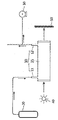
- FIG. 1 shows a brief analysis of the analysis cell of the conventional gas analyzer.
- the analysis cell 10 of the gas analyzer is, as shown in Figure 1, both ends of the body portion in the form of a cylindrical container closed at both ends, and toward both ends of the body portion 15, respectively It is arranged to include an inlet pipe 11 and the discharge pipe 12 for receiving or discharging the gas sample.
- the inlet pipe 11 is connected to the raw material container 20 containing the sample to be analyzed
- the pump pipe 30 is connected to the discharge pipe 12.
- the sample is sucked from the raw material container 20 by the suction force of the pump unit 30, and consequently flows into the analysis cell 10 through the inlet pipe 11 to the discharge pipe 12 It flows through.
- the light is analyzed.
- the light of the selective wavelength is absorbed by the gas sample flowing in the analysis cell 10 while passing through the (10).
- the light emitted through the analysis cell 10 has an absorption spectrum determined according to a gas sample, which is measured by the measurement unit 50 disposed on the other side of the analysis cell 10. That is, ultimately, by analyzing the absorption spectrum, it is possible to analyze what kind of material the gas sample in the analysis cell 10 is made of.
- a method of performing an analysis while continuously distributing a gas sample to the analysis cell 10 is commonly referred to as a continuous injection formula.
- the standard method used in this analysis is as follows. In the same manner as described above, when the analysis is first performed while passing the reference material to be the reference to the analysis cell 10, the absorption spectrum as well as the absorption spectrum of the standard material can be obtained. It is well known that this absorbance is directly related to the gas concentration in the assay cell 10 and the length of the assay cell 10. Next, the analysis is performed while passing the analyte to the assay cell 10 to obtain an absorption spectrum and an absorbance of the analyte. If the analyte is the same as the standard, the absorption spectrum will appear the same but the absorbance will be different. For example, it is known that the standard has a concentration of 1 and an absorbance of 1, but the analyte has an absorption of 0.5.
- the analyte can obtain an analysis result of [the same substance as the standard substance and concentration 0.5].
- the sample is analyzed by continuously flowing gas into the analysis cell.
- various problems in the continuous injection analysis method as follows.
- the absorbance of light passing through the analysis cell is related to the gas concentration in the analysis cell and the length of the analysis cell, and the gas concentration is obviously greatly influenced by the pressure.
- the pressure continues to change (even if there is a device to keep the flow rate constant), which causes uncertainty in absorbance measurement. Increase the reliability of the analysis results.
- Korean Patent Registration No. 1582745 Metal and Method for Manufacturing Liquid Standard Hydrocarbon Mixture Certified Standards
- Korean Patent Registration No. 1277733 Standard Source for Calibration of Radioactive Material Measuring Instrument and Its Manufacturing Method
- Korean Patent Registration No. 0656415 Liquid Injector for Standard Gas Production", 2006.12.05
- an object of the present invention is to produce a cell type in the form of a sealed container and is produced by injecting a gas of a precisely predetermined concentration by weight method
- the present invention provides a method, a manufacturing apparatus, and a container for producing a cell-type gas certified standard material, by which a predetermined concentration and length value can be produced.
- Another object of the present invention is to provide a cell type gas certified standard material manufacturing method, apparatus and container which can be manufactured in such a manner to minimize the uncertainty in the analysis and maximize the reliability of the analysis result.
- Another object of the present invention is to form a form as described above, can be analyzed in a small amount, and can be used repeatedly for unlimited within the expiration date, even if the gas having adsorption, toxicity, reactivity is dangerous to the human body or equipment
- the present invention provides a method, a manufacturing apparatus and a container for manufacturing a cell type gas certified standard material, which enable a stable analysis without any problems.
- Cell type gas certified standard material manufacturing method of the present invention for achieving the object as described above, is formed on the body 150 of the column-shaped body 150, the both ends are closed, the space is formed inside and closed
- a container manufacturing step in which the cell type container 100 including the inlet 110 and the outlet 120 provided with possible valves 115 and 125, respectively, is manufactured, and the length measurement of the length of the container 100 is measured.
- a length determining step comprising a step; As the pressure is measured at the inlet 110 of the vessel 100 in which the moisture of the source gas is removed, the purity analysis step of spectroscopic analysis of the source gas from which moisture is removed, and the source gas analyzed for purity are evacuated.
- a concentration determining step including a weight measuring step of measuring a weight of the raw material gas in the container 100 by a weight difference, and calculating a concentration using a weight value of the raw material gas in the container 100; It may be made, including.
- the length measurement step the length of the container 100 can be measured through a three-dimensional shape measurement method using a laser.
- the method for manufacturing a cell type gas certified standard material may include a container heating step in which the container 100 is heated between the length determining step and the concentration determining step, and a container in which the container 100 is evacuated in a heated state.
- a usage-based ratio step including a vacuum step and a container cooling step of cooling after the inlet 110 and the outlet 120 of the container 100 are closed; It may be made to include more.
- the reference container 100R is manufactured by injecting a predetermined reference gas into a selected one of the plurality of containers 100 by a predetermined injection amount under a predetermined pressure and temperature conditions and closing the container.
- a first value calculation step of calculating a first difference value, which is a difference between the weight and the weight of the vacuumed container 100, and a second weight at which the weights of the reference container 100R and the remaining containers 100 into which the raw material gas is injected are measured.
- Remaining container (100) For each may comprise a gas weight calculation step that calculates the weight of the raw material gas injected into a difference value between the first differential value and the second differential value.
- the weighing step is carried out by using a top-loading scale that measures the weight by placing a measurement object on the top, but the position where the measurement object is placed on the balance is kept constant.
- the weight measurement can be made by the automatic loading device.
- the cell type gas certified standard material manufacturing apparatus of the present invention in the cell type gas certified standard material manufacturing apparatus using the cell type gas certified standard material manufacturing method as described above, the moisture to pass through the source gas to remove moisture Removal device 210; Gas analyzer 220 for spectroscopic analysis of the target gas flowing through the analysis cell; A vacuum pump 230 for evacuating the container 100; Pressure gauge 240 for measuring the pressure of the raw material gas injected into the container 100; Weighing apparatus for measuring the weight of the container 100; A length measuring device measuring a length of the container 100; It may be made, including.
- the weighing apparatus may include a top-loading scale that measures a weight by placing a measurement object on an upper portion thereof, and an automatic loading device that maintains a constant position of the measurement object on the balance.
- the water removal device 210 may be made to remove water by using a freezer method or a moisture absorbent.
- the cell type gas authentication standard material manufacturing apparatus may further include a generator for producing a storage tank or raw material gas is produced and stored in advance the raw material gas.
- the cell type gas certified standard material container of the present invention in the cell type gas certified standard material container 100 used in the method for manufacturing a cell type gas certified standard material, wherein the body 150 has a space formed therein. It may include a pillar portion 151 and a pair of windows 152 provided at both ends of the pillar portion 151 and closed.
- the body 150, both ends of the body 150 may be formed perpendicular to the extending direction of the body 150.
- the body 150, the anti-reflection coating may be made to the window 152.
- the body 150 may have both ends of the body 150 inclined with respect to the extending direction of the body 150.
- the body 150, both ends of the pillar portion 151 is formed to be inclined with respect to the extending direction of the body 150, the window 152 closes the inclined cross section of the pillar portion 151 As a result, it may be disposed to be inclined with respect to the extending direction of the body 150.
- both ends of the pillar portion 151 is formed perpendicular to the extending direction of the body 150, the window 152 closes the vertical section of the pillar portion 151
- a pair of prisms disposed perpendicular to the extending direction of the body 150 and provided on the outside of each of the windows 152, wherein the window side surface is vertically formed, and the window opposite side surface is inclined. 153 may be further included.
- the body 150 may be coated in a region except for the central portion of both ends so that light can be passed only through the central portion of both ends.
- a gaseous certified reference material CCM, Certified Reference Material
- CCM Certified Reference Material
- a gas analyzer using spectroscopic analysis analyzes a sample using an absorption spectrum and an absorbance.
- the pressure of the gas sample is substantially changed during the analysis, thereby affecting the concentration and uncertainty. There was a problem of rising.
- the sample since the sample is known in advance and contained in a sealed container, the possibility of a change in concentration is basically excluded, and thus there is an effect that can completely solve this problem.
- the gas-certified standard manufactured according to the present invention when using the gas-certified standard manufactured according to the present invention as a reference, the analysis accuracy of the sample can also be greatly improved.
- the gas certified standard material manufactured according to the present invention has a great effect that it can be used for calibration of the gas analyzer itself because the uncertainty of the concentration and length is accurately evaluated in advance as described above.
- the analysis is performed using the gas in a sealed container, and thus, various effects as follows can be obtained.
- the amount of gas sample used for analysis can be drastically reduced, and accordingly, even a small amount of sample.
- the gas since the gas is safely sealed, the gas concentration is changed due to adsorption or reaction of gas having high adsorption or high reactivity as it flows in the equipment, a problem that the toxic gas leaks and harms the human body, Highly corrosive gas leaks out and has a great effect of breaking down the equipment to corrode and damage equipment.
- 1 is a schematic diagram of an analysis cell of a conventional gas analyzer.
- FIG. 2 is a flow chart of a method for manufacturing a cell type gas authentication standard material of the present invention.
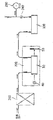
- Figure 3 is a schematic diagram of a cell type gas certification standard material manufacturing apparatus of the present invention.
- Figure 5 shows several embodiments of the cell type gas certification standard container of the present invention.
- moisture removal device 220 gas analyzer
- FIG. 2 is a flowchart of a method for manufacturing a cell type gas certified standard material of the present invention
- FIG. 3 is a schematic view of an apparatus for manufacturing cell type gas certified standard material of the present invention, respectively.
- 5 also shows various embodiments of the cell type gas certified standard material container of the present invention.
- the biggest difference from the existing is that it is a sealed type.
- the spectroscopic analysis was performed by continuous injection.
- the amount of gas required for the analysis process is excessively increased, and even if the flow rate in the analysis cell is constantly adjusted, the pressure is inevitably changed.
- the reliability is lowered.
- the reliability of the analysis result is further lowered as the gas concentration is changed by the gas being adsorbed on the pipeline or reacting with other substances such as the pipeline or moisture.
- toxic and corrosive gas there is a problem that there is a risk factor such as harmful to human body or damage to equipment by leaking gas.
- a cell type gas certification standard material is formed in a sealed form in which a raw material gas is placed in a cell type container.
- This essentially excludes the possibility of changing the concentration of gas in the vessel. That is, the gas concentration change due to the pressure change inevitably generated by the flow of the gas, or the gas concentration change due to the adsorption, reaction, etc. generated in the process of flowing the gas does not occur at all.
- the use of airtight seals minimizes the risk of leaking toxic and corrosive gases, thus maximizing safety during the analysis.
- the gas consumption is too high during the spectroscopic analysis, and since it is a closed type, it does not need any more gas other than the source gas injected into the container after it is manufactured once, so it is used unlimitedly within the expiration date. This is possible.
- gas analysis uses an absorption spectrum, which measures the extent to which light is absorbed, that is, the absorbance when light is passed through the gas to be analyzed. Absorption is directly related to concentration and length, and it is an object of the present invention to produce a certified reference material as a gas container in which the uncertainty of the concentration and length is accurately evaluated.
- the method for manufacturing a cell-type gas certified standard material of the present invention as shown in the flow chart of Figure 2, the length determination step for accurately grasping and determining the length of the container, and accurately grasp and confirm the concentration of the gas injected into the container Including the concentration determination step.
- the length determination step and the concentration determination step may further comprise a content ratio step of performing a preparatory work for injecting gas into the container.
- the length determining step includes a container manufacturing step and a length measuring step.
- the container 100 itself is produced.
- the container 100 has a shape similar to the analysis cell of the gas analyzer, so that the container 100 can be easily replaced with the analysis cell of the gas analyzer. That is, in the present invention, the container 100 has a space formed therein and a pillar-shaped body 150 having both ends closed, and formed on the body 150 and provided with opening and closing valves 115 and 125, respectively. It comprises an inlet 110 and outlet 120 which is.
- the length measuring device for measuring the length of the container 100 may be made so that the length of the container 100 is measured through a three-dimensional shape measurement method using a laser.
- a three-dimensional shape measurement method There are two methods of measuring three-dimensional shape, which can be largely contacted and non-contacted. In the case of contact type, the accuracy is guaranteed, but the measurement takes a lot of time and requires expensive equipment. Contactless methods are widely used.
- Concentration determination step to be described below, the process of injecting gas into the container 100 made in the length determination step previously. In this case, a process of preparing the container to exclude impurities such as moisture remaining in the container 100 is necessary.
- This is the usage-base ratio step, wherein the usage-base ratio step includes a container heating step, a container vacuum step, and a container cooling step.
- the vessel 100 is heated to an appropriate temperature (for example, about 50 °C). In this way, an environment in which the water in the container 100 can be evaporated and removed more smoothly is created.
- an appropriate temperature for example, about 50 °C.
- the inside of the container 100 is evacuated while the container 100 is heated. That is, by extracting air for a suitable time (for example, about 3 hours) by using equipment such as a vacuum pump, so that impurities do not remain in the container 100.
- the inlet 110 and the outlet 120 of the vessel 100 evacuated in this manner are closed and then cooled to room temperature.
- a raw material gas is injected into the container 100 to prepare a gas certification standard material.
- the concentration determination step includes a water removal step, purity analysis step, gas injection step, container sealing step, weighing step, concentration calculation step.
- a water removal device 210 for removing water by passing raw material gas may be used.
- the water removal device 210 may be a freezer method or Mg (ClO 4 ) 2. It may be made to remove moisture using an absorbent such as.
- the source gas may be supplied from a receiving tank in which the source gas has been produced and stored in advance, or may be supplied from a generator that produces the source gas.
- highly stable raw material gases such as CO 2
- the source gas from which moisture is removed is spectroscopically analyzed. More specifically, as shown in FIG. 3, spectroscopic analysis may be performed using a gas analyzer 220 that spectroscopically analyzes a target gas flowing through an analysis cell. That is, the gas analyzer 220 may be used. While passing through, the purity of the source gas is analyzed and impurities are removed well.
- the analysis cell 10 of the gas analyzer 220 may be a conventional type in which spectroscopic analysis is performed while a gas sample (as shown in FIG. 1) flows.
- the raw material gas analyzed for purity is injected while the pressure is measured to the inlet 110 of the vessel 100 in which the vacuum is evacuated. More specifically, as shown in FIG. 3, the container 100 is connected to the outlet 120 side of the container 100 by using a vacuum pump 230 for evacuating the inside of the container 100. By lowering the pressure in the c), the raw material gas is removed and the purity of the source gas can be smoothly flowed into the container 100 through the above steps.
- the pressure measurement of the source gas injected into the container 100 may be made using a pressure gauge 240 provided on the outlet 120 side of the container 100. .
- the inlet port 110 and the outlet port 120 of the container 100 is closed.
- a gas injection amount can be determined to a desired degree, and when a desired amount of gas is injected, the container 100 is provided at the inlet 110 and the outlet 120, respectively.
- the inlet valve 115 and the outlet valve 125 are closed.
- the container 100 is in a state of being sealed with the outside while injecting as much gas as desired.
- the weight of the source gas in the container 100 is measured by the difference between the weight of the container 100 into which the source gas is injected and the weight of the container 100 in a vacuum state.
- a scale of the top-loading method for measuring the weight by placing a measurement object on the top may be used.
- the weighing device preferably includes, in addition to the balance, an automatic loading device for maintaining a constant position where the measurement object is placed on the balance.
- the concentration is calculated using the weight value of the source gas in the container 100.
- the weight of the source gas in the container 100 is measured by the difference between the weight of the container 100 into which the source gas is injected and the weight of the container 100 in a vacuum state.
- the weighing step, the reference container production step, the first weighing step, the first value calculation step, the second weight measurement step, the second difference value calculation Step, gas weight calculation step can be made. Referring to Figure 4, each step is described below.
- a predetermined reference gas is injected and sealed by a predetermined injection amount under a predetermined pressure and temperature conditions to one of the selected one of the plurality of containers 100 to seal the reference container 100R.
- the reference gas may be, for example, nitrogen, and the reference container 100R may be manufactured under atmospheric pressure and room temperature conditions.
- the weight of the reference container (100R) and the remaining vacuum container 100 is measured.
- the weight of the reference container (100R) is (weight of the container itself W c + weight of the injected reference gas W gas _ref )
- the weight of the vacuumized container 100 is (The weight of the container itself W c ).
- the weighing apparatus used at this time is the maximum measurable weight of 1000g, the resolution of 0.01mg, the uncertainty can be up to 5/5000 if the weight of the injected gas is 0.05g.
- the weight of the remaining container 100 into which the reference container 100R and the source gas are injected is measured.
- the reference weight of the container (100R) is the same manner as above (weight W gas _ref the weight W c + implanted reference gas in the container itself), the container of the source gas is injected ( The weight of 100 is equal to (weight of container itself W c + weight of injected raw material gas W gas_mea ).
- the weight of the source gas injected as the difference between the first and second difference values is calculated for each of the remaining containers 100.
- the average, standard deviation, etc. of the first difference value, the second difference value, the weight of the raw material gas, etc. are obtained using the plurality of the vessels 100, thereby maximizing the uncertainty of the weight value of the raw material gas finally obtained. Can be evaluated accurately
- the container 100 has a shape similar to the analysis cell of the gas analyzer, so that the container 100 can be easily replaced with the analysis cell of the gas analyzer. Therefore, if the gas certified standard material made by the method described above is replaced with the analysis cell of the gas analyzer, the concentration and length of the gas certified standard material itself are accurately evaluated in advance, and thus the calibration of the gas analyzer may be performed based on this. . As such, by performing the calibration of the gas analyzer using the gas certified standard material and analyzing the other sample, it is obvious that the reliability of the analysis result of the other sample can be much increased.
- the gas certification standard container of the present invention needs only to be replaced with the analysis cell of the gas analyzer. That is, the container 100 has a space formed therein and an inlet port (150) formed on the body 150 and closed at both ends thereof and provided with valves 115 and 125 which can be opened and closed, respectively. 110) and the outlet 120 only need to be made, not necessarily the same shape as the analysis cell. More specifically, the body 150 includes a pillar portion 151 having a space formed therein, and a pair of windows 152 provided at both ends of the pillar portion 151 and closed. According to various needs of the user, the present invention may have various embodiments as shown in FIG. 5.
- the body 150 both ends of the body 150 is formed perpendicular to the extending direction of the body 150.
- This shape is the same shape as the analysis cell of the gas analyzer, it can be easily replaced with the analysis cell.
- the window 152 is completely facing each other, the multi-reflection is generated, there may be a problem that the reliability of the analysis result is lowered.
- the body 150, both ends of the body 150 are formed to be inclined with respect to the extending direction of the body 150, more specifically, the extension of the body 150
- Both ends of the pillar portion 151 are formed to be inclined with respect to the direction
- the window 152 is disposed to be inclined with respect to the extending direction of the body 150 by closing the inclined cross section of the pillar portion 151.
- the above-described multi reflection problem is naturally prevented by the shape.
- the body 150 has both ends of the body 150 inclined with respect to the extending direction of the body 150. More specifically, the window 152 may be formed in the body 150. By closing the vertical section of the pillar portion 151 is disposed perpendicular to the extending direction of the body 150, provided on the outside of each of the windows 152, the window side surface is formed vertically and the window The opposite side may further include a pair of prisms 153 that are formed to be inclined.
- a task such as closing and placing a window on an inclined portion may be difficult.
- the embodiment of FIG. There is an advantage that the difficulty of manufacturing is reduced.
- both ends are formed to be inclined to prevent the problem of multi-reflection, while there is a problem that the length of the container 100 varies depending on the position.
- the container length is a parameter having direct relevance, it is necessary to select the container length at an appropriate position as the reference container length.
- the length of the center portion of the container is selected as the reference length of the container, and as a configuration for implementing this, the coating may be made in an area except the center of both ends so that light can pass through only the center of both ends.
- the amount of gas sample used for analysis can be significantly reduced. Accordingly, even a small amount of samples can be analyzed as much as possible, and there are various effects that unlimited repetition can be used within an expiration date.
- the gas concentration is changed due to adsorption or reaction of gas having high adsorption or high reactivity as it flows in the equipment, a problem that the toxic gas leaks and harms the human body, Highly corrosive gas leaks out and has a great effect of breaking down the equipment to corrode and damage equipment.
Landscapes
- Physics & Mathematics (AREA)
- Chemical & Material Sciences (AREA)
- General Physics & Mathematics (AREA)
- Health & Medical Sciences (AREA)
- Life Sciences & Earth Sciences (AREA)
- Immunology (AREA)
- General Health & Medical Sciences (AREA)
- Biochemistry (AREA)
- Analytical Chemistry (AREA)
- Pathology (AREA)
- Spectroscopy & Molecular Physics (AREA)
- Engineering & Computer Science (AREA)
- Food Science & Technology (AREA)
- Medicinal Chemistry (AREA)
- Optics & Photonics (AREA)
- Combustion & Propulsion (AREA)
- Sampling And Sample Adjustment (AREA)
- Investigating Or Analysing Materials By Optical Means (AREA)
- Investigating Or Analysing Biological Materials (AREA)
Abstract
본 발명의 목적은, 밀폐용기 형태로 된 셀타입으로 되며 중량법을 이용하여 정확하게 미리 결정된 농도의 가스를 주입하여 제작함으로써, 미리 결정된 농도 및 길이 값이 알려진 셀타입 가스인증표준물질을 제조할 수 있게 하는, 셀타입 가스인증표준물질 제조방법, 제조장치 및 용기를 제공함에 있다. 본 발명의 다른 목적은, 이와 같은 방식으로 제조됨에 따라 분석 시의 불확도를 최소화하고 분석결과의 신뢰도를 극대화할 수 있는, 셀타입 가스인증표준물질 제조방법, 제조장치 및 용기를 제공함에 있다. 본 발명의 또다른 목적은, 상술한 바와 같은 형태로 이루어짐으로써 소량으로도 분석이 가능하고, 또한 유효기한 내에서 무제한 반복 사용이 가능하며, 흡착성, 독성, 반응성을 가지는 가스라도 인체 또는 장비에 위험을 주지 않고 안정적인 분석이 가능하도록 하는, 셀타입 가스인증표준물질 제조방법, 제조장치 및 용기를 제공함에 있다.
Description
본 발명은 셀타입 가스인증표준물질 제조방법, 제조장치 및 용기에 관한 것으로, 보다 상세하게는, 셀타입 가스인증표준물질을 제조함에 있어서, 독성을 띠거나 반응성이 높은 가스의 경우에도 안전 주입이 가능하며, 측정 및 분석 시 불확도를 최소화할 수 있도록 하는, 셀타입 가스인증표준물질 제조방법, 제조장치 및 용기에 관한 것이다.
표준물질(Reference Material)이란, 도량형에 있어서의 원기와 마찬가지로 화학종으로서의 표준이 될 수 있는 물질을 말하는 것으로, 대부분의 경우 순물질을 가리킨다. 표준물질은 물질의 분석, 조사, 시험 등의 기준이 되므로, 특히 높은 정확도 및 정밀도를 요구하는 분석이나 시험의 경우 이러한 표준물질이 필수적이다. 상온 및 상압 환경에서 물질의 종류에 따라 표준물질도 고체 상태, 액체 상태, 기체 상태의 여러 상을 가질 수 있다.
이처럼 순수한 물질인 표준물질이 다른 물질과 혼합되거나 반응하지 않고 안정적으로 보관이 가능하도록 하기 위해서는, 용기 자체의 구조나 밀폐 능력 등이 매우 중요하게 고려된다. 일반적으로 고체의 경우 대부분 순결정형이므로 폴리에틸렌, 유리 등과 같이 반응성이 낮은 재질로 된 시약병에 담아 보관하며, 액체의 경우 알칼리가 녹아나오는 성질이 매우 적은 특수 유리로 된 앰풀(ampoule, 한 끝을 가늘고 길게 뻗게 한 유리제 용기)에 담아 보관한다. 그리고 기체의 경우 일반적으로 셀(cell)이라고 부르는 작은 봄베에 담아 보관하게 되는데, 고체나 액체의 경우 담는 과정에서 다른 물질이 혼입되거나 반응이 일어나 버리게 될 위험성이 적은 반면 가스표준물질의 경우 이러한 위험성이 높아, 용기에 가스표준물질을 올바르게 담는 과정에 있어서도 세심한 주의가 필요한 경우가 많이 있다.
특히 액체나 기체의 경우 상술한 바와 같이 이들을 담는 용기 자체도 중요한 경우가 많기 때문에, 예를 들어 "가스표준물질"이라 하면, 말 그대로 "초고순도의 가스" 자체를 칭하는 용어로 사용될 수도 있고, "표준물질인 가스(초고순도의 가스)를 담고 있는 용기"를 칭하는 것으로 사용될 수도 있다.
한편, 가스시료를 분석하기 위한 방법으로서 분광분석법이 널리 사용되고 있다. 분광분석(spectroscopic analysis)이란 물질의 방출스펙트럼 또는 흡수스펙트럼을 조사하여 그 속에 있는 성분원소나 화합물의 종류와 양을 판정하는 방법으로서 스펙트럼분석이라고도 하며, 일반적인 화학분석에 견줘 조작이 빠르고, 소량의 시료로도 분석이 가능한 이점이 있다. 방출스펙트럼에 의한 분광분석은 원자에서 방출되는 빛의 스펙트럼이 각 원소에 따라 고유함을 이용하는 것으로서, 시료를 발광시켜 스펙트럼을 검사하고 미리 조사하여 둔 표준시료의 방출스펙트럼을 기초로 성분원소의 종류나 양을 알아내는 방법이다. 시료를 발광시키는 데는 보통시료를 한쪽 극으로 하여 아크방전을 시키거나, 기체 상태의 시료를 방전관에 채워서 방전시키는 방법이 이용된다. 흡수스펙트럼에 의한 분광분석은 다음과 같은 원리를 이용하는 것이다. 기체나 액체에 연속스펙트럼을 가진 빛을 조사하면, 그 기체나 액체 속에 존재하는 홑원소물질이나 화합물이 각각 특유한 파장의 빛을 선택적으로 흡수하므로, 투과광의 스펙트럼에는 물질의 종류에 따라 특유한 배열을 가진 흡수선이 나타난다. 따라서 어떤 양 또는 두께의 순수한 물질의 흡수스펙트럼을 많이 갖추고 있으면, 이것을 기초로 하여 미지시료의 정성분석, 알고 있는 시료의 정량분석, 시료 속에 있는 불순물의 발견 및 정량 등을 수행할 수 있다. 이것이 흡수스펙트럼에 의한 분광분석이다.
가스시료의 분광분석을 수행함에 있어서 현재 FTIR(Fourier Transform InfRared spectroscopy, 퓨리에 변환 적외선 분광기)이 널리 사용되고 있는데, 이는 광학계에 분산형의 분광기 대신에 두 개의 광속 간섭계를 이용하여 얻어지는 간섭줄무늬를 푸리에 변환하여 적외선 흡수스펙트럼을 얻는 방법이다. FTIR은 신속측정이 가능하고 미약광을 높은 S/N 비로 측정할 수 있으며, 높은 분해능을 얻을 수 있고 물결수정밀도 및 물결수재현성이 대단히 높은 특징을 갖는 등의 다양한 장점을 가지고 있어, 현재 가스시료의 분광분석을 정밀하게 하고자 할 때 가장 많이 사용되는 장치이다.
FTIR 등과 같은 가스시료의 분광분석장치(이하 간략하게 가스분석기라고 함)를 사용하여 미지시료를 분석하는 방법을 간략히 설명하면 다음과 같다. 도 1은 종래의 가스분석기의 분석셀을 간략하게 도시한 것이다. 일반적으로 가스분석기의 분석셀(10)은, 도 1에 도시된 바와 같이, 양 끝단이 막혀 있는 원통형의 용기 형태로 된 몸체부(15)와, 상기 몸체부(15)의 양 끝단 쪽으로 각각 편향되게 배치되어 가스시료를 유입받거나 배출하는 유입관(11) 및 배출관(12)을 포함하여 이루어진다. 유입관(11)에는 분석하고자 하는 시료가 담긴 원료용기(20)가 연결되며, 상기 배출관(12)에는 펌프부(30)가 연결된다. 상기 펌프부(30)가 빨아들이는 힘에 의하여 상기 원료용기(20)로부터 시료가 빨려나오며, 결과적으로 상기 유입관(11)을 통해 상기 분석셀(10)로 흘러들어가서 상기 배출관(12)을 통해 흘러나오게 된다.
이와 같이 상기 분석셀(10)에 가스시료가 연속적으로 흘러가고 있는 상태에서, 상기 분석셀(10)의 일측에서 광원(40)을 이용하여 연속스펙트럼을 가지는 광을 조사하면, 광이 상기 분석셀(10)을 지나면서 상기 분석셀(10) 내에 흘러가고 있는 가스시료에 의하여 선택적 파장의 광이 흡수된다. 이처럼 상기 분석셀(10)을 통과하여 나온 광은 가스시료에 따라 결정되는 흡수스펙트럼을 가지게 되며, 이는 상기 분석셀(10)의 타측에 배치된 측정부(50)에 의하여 측정된다. 즉, 궁극적으로는 이 흡수스펙트럼을 분석함으로써 상기 분석셀(10) 내의 가스시료가 어떤 물질로 이루어져 있는지 등을 분석해 낼 수 있게 된다. 이와 같이 연속적으로 분석셀(10)에 가스시료를 유통시키면서 분석을 수행하는 방식을 통상적으로 연속주입식이라고 한다.
이러한 분석 과정에 있어서 표준물질을 이용하는 방식은 다음과 같다. 상술한 바와 같은 방식으로, 먼저 상기 분석셀(10)에 기준이 될 표준물질을 통과시키면서 분석을 수행하면, 표준물질의 흡수스펙트럼 뿐 아니라 흡수도도 얻을 수 있다. 이러한 흡수도는 상기 분석셀(10) 내의 가스 농도 및 상기 분석셀(10)의 길이에 직접적으로 관련이 있음이 잘 알려져 있다. 다음으로, 상기 분석셀(10)에 분석대상을 통과시키면서 분석을 수행하여, 분석대상의 흡수스펙트럼 및 흡수도를 얻는다. 분석대상이 표준물질과 동일한 물질이라면, 흡수스펙트럼은 동일하게 나타나되 흡수도가 차이가 날 것이다. 예를 들어 표준물질의 경우 농도가 1이라는 것이 알려져 있고 흡수도가 1이 나왔는데, 분석대상의 경우 흡수도가 0.5가 나왔다고 가정한다. 상기 분석셀(10)의 길이는 표준물질 및 분석대상 각각의 경우에서 변화하지 않았으므로, 흡수도에 영향을 주는 것은 농도 뿐이다. 따라서 이 경우 분석대상은 [표준물질과 동일 물질로서 농도 0.5이다]라는 분석결과를 얻을 수 있게 된다.
이처럼 종래의 가스분석기에서는, 분석셀에 연속적으로 가스가 흘러가게 함으로써 시료의 분석이 이루어지도록 하였는데, 이러한 연속주입식 분석방법에는 다음과 같이 다양한 문제점들이 있었다.
먼저, 이러한 연속주입식 분석방법의 경우 분석이 수행되는 동안 연속적으로 가스시료를 흘려주어야 하므로, 가스시료의 사용량이 상당히 많다. 따라서 소량의 시료밖에 가지고 있지 못할 경우 분석과정 자체가 이루어지기 어려울 수도 있는 문제가 있다.
또한, 상술한 바와 같이 분석셀을 통과하는 광의 흡수도는 분석셀 내 가스 농도 및 분석셀의 길이에 관련된다는 점이 잘 알려져 있으며, 가스 농도의 경우 압력에 매우 크게 영향을 받게 됨은 자명하다. 그런데 이러한 연속주입식의 경우 가스시료가 연속적으로 분석셀을 통과하면서 흘러가는 과정에서 (유량을 일정하게 유지시키는 장치가 구비되어 있다 하더라도) 압력이 계속 변화하게 되며, 이는 흡수도 측정에 있어서의 불확도를 높여 분석 결과의 신뢰도를 저하시키는 원인이 된다.
또한, 흡착성이 있는 가스의 경우 분석셀로 주입되어 오는 과정에서 관로에 흡착되어 버릴 수도 있는 문제가 있다. 이 경우, 원료용기 내에 수용되어 있는 가스시료의 농도에 비해 (관로를 통과해 오는 과정에서 가스시료 일부가 관로에 흡착됨으로써) 분석셀 내를 흘러가는 가스시료의 농도가 낮아지게 됨은 당연하다. 따라서 분석셀에서의 측정 결과로서 원료용기 내의 가스시료 농도를 확정할 수 없어, 역시 분석 결과의 신뢰도를 저하시키는 원인이 된다.
뿐만 아니라 독성 가스의 경우에는, 분석셀로 가스시료를 흘려주는 과정에서 가스가 외부로 새어나가는 등의 문제가 발생할 수 있어, 분석작업 중 안전성을 담보할 수 없다는 큰 문제가 있다. 더불어 SO2, HCl, HF 등과 같이 독성일 뿐 아니라 강산성을 가지는 가스의 경우, 대기 중 수분과 만나 높은 부식성을 보이기 때문에, 분석을 수행하는 사람의 위험성 뿐만 아니라 분석장치 자체의 부식 및 손상을 초래하는 문제도 있으며, 물론 이러한 문제 때문에 분석결과가 더욱 부정확해지는 문제가 더 발생하게 됨은 자명하다.
이러한 문제를 해소할 수 있는 가스시료의 표준물질을 제조하는 방법이나 장치에 대한 필요가 점점 높아지고 있다. 그러나 현재 한국특허등록 제1582745호("액상의 탄화수소혼합물 인증표준물질 제조장치 및 방법", 2015.12.29), 한국특허등록 제1237773호("방사성 물질 계측기 교정용 표준선원 및 그 제조방법", 2013.02.21), 한국특허등록 제0656415호("표준가스 제조용 액체 주입장치", 2006.12.05) 등과 같이 액체 상태의 표준물질을 제조하는 방법이나 장치에 대한 기술들은 개시되고 있는 반면, 기체 상태의 표준물질을 제조하는 방법이나 장치에 대한 연구는 아직 많이 이루어지지 못한 실정이다.
[선행기술문헌]
[특허문헌]
1. 한국특허등록 제1582745호("액상의 탄화수소혼합물 인증표준물질 제조장치 및 방법", 2015.12.29)
2. 한국특허등록 제1237773호("방사성 물질 계측기 교정용 표준선원 및 그 제조방법", 2013.02.21)
3. 한국특허등록 제0656415호("표준가스 제조용 액체 주입장치", 2006.12.05)
따라서, 본 발명은 상기한 바와 같은 종래 기술의 문제점을 해결하기 위하여 안출된 것으로, 본 발명의 목적은, 밀폐용기 형태로 된 셀타입으로 되며 중량법을 이용하여 정확하게 미리 결정된 농도의 가스를 주입하여 제작함으로써, 미리 결정된 농도 및 길이 값이 알려진 셀타입 가스인증표준물질을 제조할 수 있게 하는, 셀타입 가스인증표준물질 제조방법, 제조장치 및 용기를 제공함에 있다. 본 발명의 다른 목적은, 이와 같은 방식으로 제조됨에 따라 분석 시의 불확도를 최소화하고 분석결과의 신뢰도를 극대화할 수 있는, 셀타입 가스인증표준물질 제조방법, 제조장치 및 용기를 제공함에 있다. 본 발명의 또다른 목적은, 상술한 바와 같은 형태로 이루어짐으로써 소량으로도 분석이 가능하고, 또한 유효기한 내에서 무제한 반복 사용이 가능하며, 흡착성, 독성, 반응성을 가지는 가스라도 인체 또는 장비에 위험을 주지 않고 안정적인 분석이 가능하도록 하는, 셀타입 가스인증표준물질 제조방법, 제조장치 및 용기를 제공함에 있다.
상기한 바와 같은 목적을 달성하기 위한 본 발명의 셀타입 가스인증표준물질 제조방법은, 내부에 공간이 형성되고 양단이 폐쇄된 기둥형의 몸체(150), 상기 몸체(150) 상에 형성되며 개폐 가능한 밸브(115)(125)가 각각 구비되는 유입구(110) 및 배출구(120)를 포함하여 이루어지는 셀타입 용기(100)가 제작되는 용기제작단계, 상기 용기(100)의 길이가 측정되는 길이측정단계를 포함하여 이루어지는 길이확정단계; 원료가스의 수분이 제거되는 수분제거단계, 수분이 제거된 원료가스가 분광분석되는 순도분석단계, 순도가 분석된 원료가스가 진공화된 상기 용기(100)의 유입구(110)로 압력이 측정되면서 주입되는 가스주입단계, 상기 용기(100)의 유입구(110) 및 배출구(120)가 폐쇄되는 용기밀폐단계, 원료가스가 주입된 상기 용기(100)의 중량 및 진공 상태의 상기 용기(100)의 중량 차이로 상기 용기(100) 내 원료가스의 중량이 측정되는 중량측정단계, 상기 용기(100) 내 원료가스의 중량 값을 이용하여 농도가 산출되는 농도산출단계를 포함하여 이루어지는 농도확정단계; 를 포함하여 이루어질 수 있다.
이 때 상기 길이측정단계는, 레이저를 이용한 3차원 형상 측정법을 통해 상기 용기(100)의 길이가 측정될 수 있다.
또한 상기 셀타입 가스인증표준물질 제조방법은, 상기 길이확정단계 및 상기 농도확정단계 사이에, 상기 용기(100)가 가열되는 용기가열단계, 가열된 상태에서 상기 용기(100) 내가 진공화되는 용기진공단계, 상기 용기(100)의 유입구(110) 및 배출구(120)가 폐쇄된 후 냉각되는 용기냉각단계를 포함하여 이루어지는 용기준비단계; 를 더 포함하여 이루어질 수 있다.
또한 상기 중량측정단계는, 복수 개의 용기(100)들 중 선택된 하나의 용기(100)에 미리 결정된 기준가스가 미리 결정된 압력 및 온도 조건 하에 미리 결정된 주입량만큼 주입되어 밀폐됨으로써 기준용기(100R)가 제작되는 기준용기제작단계, 상기 기준용기(100R) 및 진공화된 나머지 용기(100)들의 중량이 측정되는 제1중량측정단계, 진공화된 나머지 용기(100)들 각각에 대하여 상기 기준용기(100R) 중량 및 진공화된 용기(100) 중량의 차이 값인 제1차값이 산출되는 제1차값산출단계, 상기 기준용기(100R) 및 원료가스가 주입된 나머지 용기(100)들의 중량이 측정되는 제2중량측정단계, 원료가스가 주입된 나머지 용기(100)들 각각에 대하여 상기 기준용기(100R) 중량 및 원료가스가 주입된 용기(100) 중량의 차이 값인 제2차값이 산출되는 제2차값산출단계, 나머지 용기(100)들 각각에 대하여 제1차값 및 제2차값의 차이 값으로서 주입된 원료가스의 중량이 산출되는 가스중량산출단계를 포함하여 이루어질 수 있다.
또한 이 때 상기 중량측정단계는, 상부에 측정대상물을 올려놓아 중량을 측정하는 탑-로딩 방식의 저울을 사용하여 중량 측정이 이루어지되, 상기 저울 상에 측정대상물이 놓이는 위치가 일정하게 유지되게 하는 자동로딩장치에 의해 중량 측정이 이루어질 수 있다.
또한 본 발명의 셀타입 가스인증표준물질 제조장치는, 상술한 바와 같은 셀타입 가스인증표준물질 제조방법을 사용하는 셀타입 가스인증표준물질 제조장치에 있어서, 원료가스를 통과시켜 수분을 제거하는 수분제거장치(210); 분석셀을 통과하여 유통되는 대상가스를 분광분석하는 가스분석기(220); 상기 용기(100) 내를 진공화하는 진공펌프(230); 상기 용기(100) 내에 주입되는 원료가스의 압력을 측정하는 압력계(240); 상기 용기(100)의 중량을 측정하는 중량측정장치; 상기 용기(100)의 길이를 측정하는 길이측정장치; 를 포함하여 이루어질 수 있다.
이 때 상기 중량측정장치는, 상부에 측정대상물을 올려놓아 중량을 측정하는 탑-로딩 방식의 저울 및 상기 저울 상에 측정대상물이 놓이는 위치가 일정하게 유지되게 하는 자동로딩장치를 포함하여 이루어질 수 있다.
또한 상기 수분제거장치(210)는, 냉동기법 또는 흡습제를 사용하여 수분을 제거하도록 이루어질 수 있다.
또한 상기 셀타입 가스인증표준물질 제조장치는, 원료가스가 미리 생산되어 수용 보관된 수용탱크 또는 원료가스를 생산하는 제너레이터를 더 포함하여 이루어질 수 있다.
또한 본 발명의 셀타입 가스인증표준물질 용기는, 셀타입 가스인증표준물질 제조방법에 사용되는 셀타입 가스인증표준물질 용기(100)에 있어서, 상기 몸체(150)는, 내부에 공간이 형성되는 기둥부(151)와, 상기 기둥부(151)의 양단에 각각 구비되어 폐쇄하는 한 쌍의 윈도우(152)를 포함하여 이루어질 수 있다.
이 때 상기 몸체(150)는, 상기 몸체(150)의 연장 방향에 대하여 상기 몸체(150)의 양단이 수직하게 형성될 수 있다. 이 때 상기 몸체(150)는, 상기 윈도우(152)에 멀티리플렉션 방지용 코팅이 이루어질 수 있다.
또는 상기 몸체(150)는, 상기 몸체(150)의 연장 방향에 대하여 상기 몸체(150)의 양단이 경사지게 형성될 수 있다.
이 때 상기 몸체(150)는, 상기 몸체(150)의 연장 방향에 대하여 상기 기둥부(151)의 양단이 경사지게 형성되며, 상기 윈도우(152)는 상기 기둥부(151)의 경사진 단면을 폐쇄함으로써 상기 몸체(150)의 연장 방향에 대하여 경사지게 배치될 수 있다.
또는 상기 몸체(150)는, 상기 몸체(150)의 연장 방향에 대하여 상기 기둥부(151)의 양단이 수직하게 형성되며, 상기 윈도우(152)는 상기 기둥부(151)의 수직한 단면을 폐쇄함으로써 상기 몸체(150)의 연장 방향에 대하여 수직하게 배치되고, 각각의 상기 윈도우(152)의 외측에 구비되되 상기 윈도우측 면은 수직하게 형성되고 상기 윈도우반대측 면은 경사지게 형성되는 한 쌍의 프리즘(153)을 더 포함하여 이루어질 수 있다.
또한 상기 몸체(150)는, 양단의 중심부를 통해서만 광의 통과가 가능하도록, 양단의 중심부를 제외한 영역에 코팅이 이루어질 수 있다.
본 발명에 의하면, 밀폐용기 형태로 된 셀에 미리 결정된 농도의 가스를 중량법을 이용하여 정확하게 주입하여 제조함으로써, 농도 및 길이의 불확도가 정확히 평가되어 있는 가스상의 인증표준물질(CRM, Certified Reference Material), 즉 가스인증표준물질을 제조할 수 있게 되는 큰 효과가 있다. 잘 알려진 바와 같이 분광분석을 이용하는 가스분석기에서는 흡수스펙트럼 및 흡수도를 이용하여 시료를 분석하되, 기존에는 연속주입법을 사용하였기 때문에 분석 중 실질적으로 가스 시료의 압력이 변화함으로써 농도에 영향을 미쳐 불확도가 높아지는 문제가 있었다. 그러나 본 발명에 의하면, 시료가 미리 결정되어 알려지며 밀폐 용기에 담겨 있으므로 농도의 변화가 발생할 가능성이 원천적으로 배제되어 이러한 문제를 완전히 해결할 수 있는 효과가 있다. 물론 이에 따라 본 발명에 의하여 제조된 가스인증표준물질을 기준으로 삼을 경우, 시료의 분석 정확도 역시 크게 향상되는 효과를 얻을 수 있다. 뿐만 아니라 본 발명에 의하여 제조된 가스인증표준물질은 상술한 바와 같이 농도 및 길이의 불확도가 미리 정확히 평가되어 있기 때문에, 가스분석기 자체의 교정에도 사용될 수 있다는 큰 효과가 있다.
이처럼 본 발명에 의하면 기존의 연속주입법과는 달리 밀폐된 용기 내의 가스를 사용하여 분석을 수행한다는 점에서, 다음과 같은 다양한 효과들을 더 얻을 수 있다. 먼저 연속주입법의 경우 그 방법론 자체의 한계로 인하여 시료가 소량일 경우 종래에는 분석 자체가 불가능하였으나, 본 발명에 따르면 분석에 사용되는 가스시료의 사용량을 획기적으로 줄일 수 있으며, 이에 따라 소량의 시료도 얼마든지 분석이 가능하고, 유효기간 내에서 무제한 반복 사용이 가능하다는 다양한 효과들이 있다. 또한 본 발명에 따르면 가스가 안전하게 밀폐되어 있기 때문에, 흡착성이나 반응성이 높은 가스가 장비 내를 흘러가면서 흡착 또는 반응을 일으켜 가스 농도가 달라지는 문제, 독성을 가진 가스가 새어나와 인체에 해를 주는 문제, 부식성이 높은 가스가 새어나와 장비를 부식 및 손상시키는 문제 등을 일거에 타파하는 커다란 효과가 있다.
도 1은 종래의 가스분석기의 분석셀 개략도.
도 2는 본 발명의 셀타입 가스인증표준물질 제조방법의 흐름도.
도 3은 본 발명의 셀타입 가스인증표준물질 제조장치의 개략도.
도 4는 중량측정단계의 구체적인 실시예.
도 5는 본 발명의 셀타입 가스인증표준물질 용기의 여러 실시예.
** 부호의 설명 **
10: 분석셀
20: 원료용기 30: 펌프부
40: 광원 50: 측정부
100: 용기
110: 유입구 115: 유입구밸브
120: 배출구 125: 배출구밸브
150: 몸체 151: 기둥부
152: 윈도우 153: 프리즘
210: 수분제거장치 220: 가스분석기
230: 진공펌프 240: 압력계
이하, 상기한 바와 같은 구성을 가지는 본 발명에 의한 셀타입 가스인증표준물질 제조방법, 제조장치 및 용기를 첨부된 도면을 참고하여 상세하게 설명한다.
도 2는 본 발명의 셀타입 가스인증표준물질 제조방법의 흐름도를, 도 3은 본 발명의 셀타입 가스인증표준물질 제조장치의 개략도를 각각 도시하고 있다. 또한 도 5는 본 발명의 셀타입 가스인증표준물질 용기의 여러 실시예를 도시하고 있다.
본 발명의 셀타입 가스인증표준물질에 있어서, 기존과 가장 크게 다른 점은 바로 밀폐형이라는 것이다. 앞서 설명한 바와 같이 기존에는 연속주입식으로 분광분석을 수행하였는데, 이에 따라 분석 과정에 필요한 가스 사용량이 지나치게 많아지며, 분석셀 내 유량을 일정하게 조절한다 하더라도 필연적으로 압력의 변화가 발생하기 때문에 분석 결과의 신뢰도가 저하되는 문제가 있었다. 또한 흡착성, 반응성 가스의 경우에는 가스를 흘려주는 과정에서 가스가 관로 상에 흡착되거나 관로 또는 수분 등과 같은 타 물질과 반응을 일으켜 가스 농도가 달라짐에 따라 분석 결과의 신뢰도가 더욱 저하되는 문제도 있었다. 뿐만 아니라 독성, 부식성 가스의 경우에는 가스가 새어나옴으로써 인체에 해롭거나 장비가 손상되는 등의 위험성 요인이 있는 문제도 있었다.
그러나 본 발명에서는, 셀타입 용기에 원료가스를 넣고 밀폐시킨 형태로서 셀타입 가스인증표준물질을 형성한다. 이에 따라 용기 내 가스의 농도가 변화될 가능성을 원천적으로 배제한다. 즉 가스가 흘러감으로써 필연적으로 발생되는 압력 변화에 의한 가스 농도 변화나, 가스를 흘려주는 과정에서 발생되는 흡착, 반응 등에 의한 가스 농도 변화가 전혀 발생하지 않게 되는 것이다. 뿐만 아니라 밀폐된 상태로 사용하기 때문에 독성, 부식성 가스가 새어나올 위험성도 극소화되며, 따라서 분석 과정에서의 안전성도 극대화된다. 또한 연속주입식 방법을 사용할 경우 분광분석 시 가스 사용량이 지나치게 많아지는 것과는 달리, 밀폐형이기 때문에 한 번 제작한 후에는 용기 내 주입된 원료가스 외에 더 이상의 가스가 필요하지 않아, 유효기한 내에서 무제한 반복 사용이 가능하다.
[가스인증표준물질 제조방법 및 제조장치]
이 때, 단순히 용기에 가스를 주입하고 밀폐시키기만 해서는 가스인증표준물질이라 하기에 부족하다. 앞서도 설명하였듯이 가스 분석은 흡수스펙트럼을 이용하는 것으로, 실질적으로는 분석대상인 가스로 광을 통과시켰을 때 광이 흡수된 정도, 즉 흡수도를 측정하게 된다. 흡수도는 농도 및 길이와 직접적으로 관련되는데, 본 발명에서는 바로 이러한 농도 및 길이의 불확도가 정확하게 평가되어 있는 가스 용기로서의 가스인증표준물질(Certified Reference Material)을 제조하고자 하는 것이 목적인 것이다.
이를 위하여 본 발명의 셀타입 가스인증표준물질 제조방법은, 도 2의 흐름도에 나타난 바와 같이, 용기의 길이를 정확하게 파악 및 확정하는 길이확정단계와, 용기에 주입되는 가스의 농도를 정확하게 파악 및 확정하는 농도확정단계를 포함하여 이루어진다. 이 때 길이확정단계 및 농도확정단계 사이에, 역시 도 2의 흐름도에 나타난 바와 같이, 용기에 가스를 주입하기 위한 준비 작업을 하는 용기준비단계를 더 포함하여 이루어질 수 있다. 이하 각 단계에 대하여 보다 상세히 설명한다.
길이확정단계
상기 길이확정단계는, 용기제작단계, 길이측정단계를 포함하여 이루어진다.
먼저 상기 용기제작단계에서는, 말 그대로 용기(100) 자체가 제작된다. 본 발명에서 상기 용기(100)는 가스분석기의 분석셀과 유사한 형상으로 되어 있도록 함으로써, 가스분석기의 분석셀과 쉽게 교체가 가능하게 한다. 즉 본 발명에서 상기 용기(100)는, 내부에 공간이 형성되고 양단이 폐쇄된 기둥형의 몸체(150), 상기 몸체(150) 상에 형성되며 개폐 가능한 밸브(115)(125)가 각각 구비되는 유입구(110) 및 배출구(120)를 포함하여 이루어진다.
다음으로 상기 길이측정단계에서는, 상술한 바와 같이 만들어진 상기 용기(100)의 길이가 측정된다. 이 때 상기 용기(100)의 길이를 측정하는 길이측정장치는, 레이저를 이용한 3차원 형상 측정법을 통해 상기 용기(100)의 길이가 측정되도록 이루어질 수 있다. 3차원 형상을 측정하는 방법으로는 크게 접촉식 및 비접촉식이 있을 수 있는데, 접촉식의 경우 정밀성이 보장되는 반면 측정에 많은 시간이 걸리고 고가의 장비가 필요한 등의 제약이 있어, 레이저 및 카메라를 이용한 비접촉식 방법이 널리 사용된다. 일반적으로 레이저를 이용한 3차원 형상 측정법으로서 포인트광 방식(Point Beam Projection), 슬릿광 방식(Slit Beam Projection), 모아레 방식(Moire Method), 위상측정 방식 등 여러 가지가 잘 알려져 있으며, 이 중 적절한 방식을 선택하여 사용하면 된다.
용기준비단계
이하에서 설명될 농도확정단계에는, 앞서 길이확정단계에서 만들어진 상기 용기(100)에 가스를 주입하는 과정이 포함된다. 이 때 상기 용기(100) 내에 수분 등의 불순물이 잔존해 있는 것을 배제하도록 용기를 준비시키는 과정이 필요하다. 바로 이것이 용기준비단계로서, 상기 용기준비단계는, 용기가열단계, 용기진공단계, 용기냉각단계를 포함하여 이루어진다.
먼저 상기 용기가열단계에서는, 상기 용기(100)가 적절한 온도(예를 들어 50℃ 가량)로 가열되게 한다. 이와 같이 함으로써 상기 용기(100) 내의 수분이 보다 원활하게 증발되어 제거될 수 있는 환경이 조성된다.
다음으로 상기 용기진공단계에서는, 상기 용기(100)가 가열된 상태에서 상기 용기(100) 내가 진공화되게 한다. 즉 진공펌프 등과 같은 장비를 이용하여 적절한 시간(예를 들어 3시간 가량) 동안 공기를 뽑아냄으로써, 상기 용기(100) 내에 불순물이 잔존하지 않도록 한다.
마지막으로 상기 용기냉각단계에서는, 이처럼 진공화된 상기 용기(100)의 유입구(110) 및 배출구(120)가 폐쇄되도록 한 후 상온까지 냉각이 이루어지게 한다. 이 상태가 되면 상기 용기(100)에 원료가스를 주입하여 가스인증표준물질을 제조할 준비가 완료된다.
농도확정단계
상기 농도확정단계는, 수분제거단계, 순도분석단계, 가스주입단계, 용기밀폐단계, 중량측정단계, 농도산출단계를 포함하여 이루어진다.
먼저 상기 수분제거단계에서는, 외부로부터 공급되어 온 원료가스의 수분이 제거된다. 보다 구체적으로는, 도 3에 도시된 바와 같이, 원료가스를 통과시켜 수분을 제거하는 수분제거장치(210)가 사용될 수 있는데, 상기 수분제거장치(210)는 냉동기법 또는 Mg(ClO4)2 등과 같은 흡습제를 사용하여 수분을 제거하도록 이루어질 수 있다. 한편 이 때 원료가스는, 원료가스가 미리 생산되어 수용 보관된 수용탱크로부터 공급될 수도 있고, 원료가스를 생산하는 제너레이터로부터 공급될 수도 있다. CO2 등과 같이 안정성이 높은 원료가스의 경우에는 가스 생산 회사 등에서 수용탱크에 넣어 판매되는 제품을 구매하여 사용하여도 무방하나, N2O, 오존 등과 같이 반응성이 높은 원료가스의 경우 오랫동안 보관이 어려운 등의 문제가 있으므로, 제너레이터를 이용하여 직접 생산하는 것이 바람직한 것이다.
다음으로 상기 순도분석단계에서는, 수분이 제거된 원료가스가 분광분석된다. 보다 구체적으로는, 역시 도 3에 도시된 바와 같이, 분석셀을 통과하여 유통되는 대상가스를 분광분석하는 가스분석기(220)를 사용하여 분광분석이 이루어질 수 있다.즉 상기 가스분석기(220)를 통과시키면서 원료가스의 순도를 분석하고 불순물이 잘 제거되었는지 확인하는 것이다. 이 때 가스분석기(220)의 분석셀(10)은, (도 1에 도시된 바와 같은) 가스 시료가 흘러가면서 분광분석이 이루어지는 기존 형태일 수 있다.
다음으로 상기 가스주입단계에서는, 순도가 분석된 원료가스가 진공화된 상기 용기(100)의 유입구(110)로 압력이 측정되면서 주입된다. 보다 구체적으로는, 역시 도 3에 도시된 바와 같이, 상기 용기(100)의 배출구(120) 측에 연결되어 상기 용기(100) 내를 진공화하는 진공펌프(230)를 이용하여 상기 용기(100) 내 압력을 낮춤으로써, 앞서의 단계들을 거치면서 수분이 제거되고 순도가 확인된 원료가스가 상기 용기(100) 내로 원활하게 흘러들어올 수 있게 되는 것이다. 이 때 상기 용기(100) 내에 주입되는 원료가스의 압력 측정은, 역시 도 3에 도시된 바와 같이, 상기 용기(100)의 배출구(120) 측에 구비된 압력계(240)를 이용하여 이루어질 수 있다.
다음으로 상기 용기밀폐단계에서는, 상기 용기(100)의 유입구(110) 및 배출구(120)가 폐쇄된다. 상기 가스주입단계에서 압력을 측정해 가면서 가스를 주입함으로써 대략 원하는 정도로 가스 주입량을 결정지을 수 있으며, 원하는 만큼의 가스가 주입되면 상기 용기(100) 유입구(110) 및 배출구(120)에 각각 구비된 유입구밸브(115) 및 배출구밸브(125)를 폐쇄한다. 이로써 상기 용기(100) 내에는 대략 원하는 만큼의 가스가 주입된 채 외부와 밀폐된 상태가 된다.
다음으로 상기 중량측정단계에서는, 원료가스가 주입된 상기 용기(100)의 중량 및 진공 상태의 상기 용기(100)의 중량 차이로 상기 용기(100) 내 원료가스의 중량이 측정된다. 상기 용기(100)의 중량을 측정하는 중량측정장치로서, 상부에 측정대상물을 올려놓아 중량을 측정하는 탑-로딩 방식의 저울이 사용될 수 있다. 이 때 측정대상물이 놓이는 위치 즉 로딩 포지션이 달라질 경우 중량 측정에 있어서의 불확도가 높아지는 문제가 있다. 이러한 문제를 방지하기 위해서 상기 중량측정장치는, 상기 저울과 더불어, 상기 저울 상에 측정대상물이 놓이는 위치가 일정하게 유지되게 하는 자동로딩장치를 포함하여 이루어지는 것이 바람직하다.
마지막으로 상기 농도산출단계에서는, 상기 용기(100) 내 원료가스의 중량 값을 이용하여 농도가 산출된다.
중량측정단계의 구체적인 실시예
앞서 상기 중량측정단계에서는, 원료가스가 주입된 상기 용기(100)의 중량 및 진공 상태의 상기 용기(100)의 중량 차이로 상기 용기(100) 내 원료가스의 중량이 측정된다고 설명하였다. 이 때 중량 측정이 보다 정확하게 이루어지도록 하기 위한 보다 구체적인 실시예로서, 상기 중량측정단계는, 기준용기제작단계, 제1중량측정단계, 제1차값산출단계, 제2중량측정단계, 제2차값산출단계, 가스중량산출단계를 포함하여 이루어질 수 있다. 도 4를 참조하여 각 단계를 설명하면 다음과 같다.
먼저 상기 기준용기제작단계에서는, 복수 개의 용기(100)들 중 선택된 하나의 용기(100)에 미리 결정된 기준가스가 미리 결정된 압력 및 온도 조건 하에 미리 결정된 주입량만큼 주입되어 밀폐됨으로써 기준용기(100R)가 제작된다. 기준가스는 예를 들어 질소일 수 있으며, 대기압 및 상온 조건으로 상기 기준용기(100R)가 제작될 수 있다.
다음으로 상기 제1중량측정단계에서는, 상기 기준용기(100R) 및 진공화된 나머지 용기(100)들의 중량이 측정된다. 이 때 도 4에 도시된 바와 같이, 상기 기준용기(100R)의 중량은 (용기 자체의 중량 Wc + 주입된 기준가스의 중량 Wgas
_ref)가 되며, 진공화된 용기(100)의 중량은 (용기 자체의 중량 Wc)이 된다. 한편 예를 들어 이 때 사용되는 중량측정장치가 측정가능최대중량 1000g, 분해능 0.01mg인 것일 경우, 주입된 가스의 중량이 0.05g이라면 불확도는 5/5000까지 가능하다.
다음으로 상기 제1차값산출단계에서는, 진공화된 나머지 용기(100)들 각각에 대하여 상기 기준용기(100R) 중량 및 진공화된 용기(100) 중량의 차이 값인 제1차값이 산출된다. 즉 제1차값은, (Wc + Wgas_ref) - (Wc) = Wgas_ref 가 된다.
다음으로 상기 제2중량측정단계에서는, 상기 기준용기(100R) 및 원료가스가 주입된 나머지 용기(100)들의 중량이 측정된다. 이 때 도 4에 도시된 바와 같이, 상기 기준용기(100R)의 중량은 앞서와 마찬가지로 (용기 자체의 중량 Wc + 주입된 기준가스의 중량 Wgas
_ref)가 되며, 원료가스가 주입된 용기(100)의 중량은 (용기 자체의 중량 Wc + 주입된 원료가스의 중량 Wgas_mea)이 된다.
다음으로 상기 제2차값산출단계에서는, 원료가스가 주입된 나머지 용기(100)들 각각에 대하여 상기 기준용기(100R) 중량 및 원료가스가 주입된 용기(100) 중량의 차이 값인 제2차값이 산출된다. 즉 제2차값은, (Wc + Wgas
_ref) - (Wc + Wgas
_mea) = Wgas_ref - Wgas_mea 가 된다.
마지막으로 상기 가스중량산출단계에서는, 나머지 용기(100)들 각각에 대하여 제1차값 및 제2차값의 차이 값으로서 주입된 원료가스의 중량이 산출된다. 즉 제1차값 및 제2차값의 차이 값은, Wgas
_ref - (Wgas
_ref - Wgas
_mea) = Wgas
_
mea 로서, 용기(100) 내 주입된 원료가스의 중량이 되는 것이다.
상술한 바와 같이 복수 개의 상기 용기(100)들을 사용하여 제1차값, 제2차값, 원료가스의 중량 등의 평균, 표준편차 등을 구함으로써, 최종적으로 구해지는 원료가스의 중량 값의 불확도를 최대한 정확하게 평가할 수 있다.
[가스인증표준물질 용기]
앞서 설명한 바와 같이, 본 발명에서는 상기 용기(100)는 가스분석기의 분석셀과 유사한 형상으로 되어 있도록 함으로써, 가스분석기의 분석셀과 쉽게 교체가 가능하게 한다. 따라서 상술한 바와 같은 방법으로 만들어진 가스인증표준물질을 가스분석기의 분석셀과 교체해 넣으면, 가스인증표준물질 자체의 농도 및 길이는 미리 정확하게 평가되어 있으므로, 이를 기준으로 가스분석기의 교정을 수행할 수도 있다. 이와 같이 가스인증표준물질을 사용하여 가스분석기의 교정을 수행한 후 다른 시료를 분석함으로써, 궁극적으로 다른 시료의 분석 결과 신뢰도를 훨씬 상승시킬 수 있게 됨은 자명하다.
이처럼 본 발명의 가스인증표준물질 용기는 가스분석기의 분석셀과 교체가 가능하기만 하면 된다. 즉 상기 용기(100)는, 내부에 공간이 형성되고 양단이 폐쇄된 기둥형의 몸체(150), 상기 몸체(150) 상에 형성되며 개폐 가능한 밸브(115)(125)가 각각 구비되는 유입구(110) 및 배출구(120)를 포함하여 이루어지기만 하면 되며, 분석셀과 반드시 완전하게 동일한 형상일 필요는 없다. 좀더 구체적으로, 상기 몸체(150)는, 내부에 공간이 형성되는 기둥부(151)와, 상기 기둥부(151)의 양단에 각각 구비되어 폐쇄하는 한 쌍의 윈도우(152)를 포함하여 이루어지되, 사용자의 여러 필요에 따라 도 5에 도시된 바와 같이 다양한 실시형태를 가질 수 있다.
도 5(A)의 실시예에서 상기 몸체(150)는, 상기 몸체(150)의 연장 방향에 대하여 상기 몸체(150)의 양단이 수직하게 형성된다. 이러한 형상은 가스분석기의 분석셀과 동일한 형상으로서, 분석셀과의 교체가 가장 용이하게 이루어질 수 있다. 한편 이와 같이 형성되는 경우, 상기 윈도우(152)가 서로 완전히 마주보고 있음으로써 멀티리플렉션이 발생되어 분석 결과의 신뢰도가 떨어지는 문제가 생길 수 있다. 이러한 문제를 방지하기 위하여, 상기 윈도우(152)에 멀티리플렉션 방지용 코팅(예를 들어 Ar 코팅)이 이루어지게 하는 것이 바람직하다.
도 5(B)의 실시예에서 상기 몸체(150)는, 상기 몸체(150)의 연장 방향에 대하여 상기 몸체(150)의 양단이 경사지게 형성되는데, 보다 구체적으로는, 상기 몸체(150)의 연장 방향에 대하여 상기 기둥부(151)의 양단이 경사지게 형성되며, 상기 윈도우(152)는 상기 기둥부(151)의 경사진 단면을 폐쇄함으로써 상기 몸체(150)의 연장 방향에 대하여 경사지게 배치된다. 이와 같이 할 경우 그 형상에 의하여 상술한 바와 같은 멀티리플렉션 문제가 자연히 방지된다.
도 5(C)의 실시예에서 상기 몸체(150)는, 상기 몸체(150)의 연장 방향에 대하여 상기 몸체(150)의 양단이 경사지게 형성되는데, 보다 구체적으로는, 상기 윈도우(152)는 상기 기둥부(151)의 수직한 단면을 폐쇄함으로써 상기 몸체(150)의 연장 방향에 대하여 수직하게 배치되고, 각각의 상기 윈도우(152)의 외측에 구비되되 상기 윈도우측 면은 수직하게 형성되고 상기 윈도우반대측 면은 경사지게 형성되는 한 쌍의 프리즘(153)을 더 포함하여 이루어질 수 있다. 도 5(B)의 실시예의 경우 구조적 개념은 단순한 반면 경사진 부분에 윈도우를 배치시켜 밀폐하는 등의 작업이 난해해질 우려가 있는데, 도 5(C)의 실시예의 경우 부품이 많아지는 대신 작업 자체의 난이도가 저하되어 제작이 용이해지는 장점이 있다.
한편, 도 5(B), (C)의 실시예 모두에서, 양단이 경사지게 형성됨으로서 멀티리플렉션 문제가 방지되는 한편으로, 위치에 따라 상기 용기(100)의 길이가 달라지는 문제가 있다. 앞서 설명한 바와 같이 흡수도 측정에 있어서 용기 길이는 직접적인 관련성을 가지는 파라미터이므로, 적절한 위치에서의 용기 길이를 기준 용기 길이로서 선택하여 줄 필요가 있다. 바람직하게는 용기 중심부 길이를 기준 용기 길이로 선택하되, 이를 구현하는 구성으로서, 양단의 중심부를 통해서만 광의 통과가 가능하도록, 양단의 중심부를 제외한 영역에 코팅이 이루어지게 할 수 있다.
본 발명은 상기한 실시예에 한정되지 아니하며, 적용범위가 다양함은 물론이고, 청구범위에서 청구하는 본 발명의 요지를 벗어남이 없이 당해 본 발명이 속하는 분야에서 통상의 지식을 가진 자라면 누구든지 다양한 변형 실시가 가능한 것은 물론이다.
본 발명에 따르면 분석에 사용되는 가스시료의 사용량을 획기적으로 줄일 수 있으며, 이에 따라 소량의 시료도 얼마든지 분석이 가능하고, 유효기간 내에서 무제한 반복 사용이 가능하다는 다양한 효과들이 있다. 또한 본 발명에 따르면 가스가 안전하게 밀폐되어 있기 때문에, 흡착성이나 반응성이 높은 가스가 장비 내를 흘러가면서 흡착 또는 반응을 일으켜 가스 농도가 달라지는 문제, 독성을 가진 가스가 새어나와 인체에 해를 주는 문제, 부식성이 높은 가스가 새어나와 장비를 부식 및 손상시키는 문제 등을 일거에 타파하는 커다란 효과가 있다.
Claims (16)
- 내부에 공간이 형성되고 양단이 폐쇄된 기둥형의 몸체, 상기 몸체 상에 형성되며 개폐 가능한 밸브가 각각 구비되는 유입구 및 배출구를 포함하여 이루어지는 셀타입 용기가 제작되는 용기제작단계, 상기 용기의 길이가 측정되는 길이측정단계를 포함하여 이루어지는 길이확정단계;원료가스의 수분이 제거되는 수분제거단계, 수분이 제거된 원료가스가 분광분석되는 순도분석단계, 순도가 분석된 원료가스가 진공화된 상기 용기의 유입구로 압력이 측정되면서 주입되는 가스주입단계, 상기 용기의 유입구 및 배출구가 폐쇄되는 용기밀폐단계, 원료가스가 주입된 상기 용기의 중량 및 진공 상태의 상기 용기의 중량 차이로 상기 용기 내 원료가스의 중량이 측정되는 중량측정단계, 상기 용기 내 원료가스의 중량 값을 이용하여 농도가 산출되는 농도산출단계를 포함하여 이루어지는 농도확정단계;를 포함하여 이루어지는 것을 특징으로 하는 셀타입 가스인증표준물질 제조방법.
- 제 1항에 있어서, 상기 길이측정단계는,레이저를 이용한 3차원 형상 측정법을 통해 상기 용기의 길이가 측정되는 것을 특징으로 하는 셀타입 가스인증표준물질 제조방법.
- 제 1항에 있어서, 상기 셀타입 가스인증표준물질 제조방법은,상기 길이확정단계 및 상기 농도확정단계 사이에,상기 용기가 가열되는 용기가열단계, 가열된 상태에서 상기 용기 내가 진공화되는 용기진공단계, 상기 용기의 유입구 및 배출구가 폐쇄된 후 냉각되는 용기냉각단계를 포함하여 이루어지는 용기준비단계;를 더 포함하여 이루어지는 것을 특징으로 하는 셀타입 가스인증표준물질 제조방법.
- 제 1항에 있어서, 상기 중량측정단계는,복수 개의 용기들 중 선택된 하나의 용기에 미리 결정된 기준가스가 미리 결정된 압력 및 온도 조건 하에 미리 결정된 주입량만큼 주입되어 밀폐됨으로써 기준용기가 제작되는 기준용기제작단계,상기 기준용기 및 진공화된 나머지 용기들의 중량이 측정되는 제1중량측정단계,진공화된 나머지 용기들 각각에 대하여 상기 기준용기 중량 및 진공화된 용기 중량의 차이 값인 제1차값이 산출되는 제1차값산출단계,상기 기준용기 및 원료가스가 주입된 나머지 용기들의 중량이 측정되는 제2중량측정단계,원료가스가 주입된 나머지 용기들 각각에 대하여 상기 기준용기 중량 및 원료가스가 주입된 용기 중량의 차이 값인 제2차값이 산출되는 제2차값산출단계,나머지 용기들 각각에 대하여 제1차값 및 제2차값의 차이 값으로서 주입된 원료가스의 중량이 산출되는 가스중량산출단계를 포함하여 이루어지는 것을 특징으로 하는 셀타입 가스인증표준물질 제조방법.
- 제 4항에 있어서, 상기 중량측정단계는,상부에 측정대상물을 올려놓아 중량을 측정하는 탑-로딩 방식의 저울을 사용하여 중량 측정이 이루어지되, 상기 저울 상에 측정대상물이 놓이는 위치가 일정하게 유지되게 하는 자동로딩장치에 의해 중량 측정이 이루어지는 것을 특징으로 하는 셀타입 가스인증표준물질 제조방법.
- 제 1항에 따른 셀타입 가스인증표준물질 제조방법을 사용하는 셀타입 가스인증표준물질 제조장치에 있어서,원료가스를 통과시켜 수분을 제거하는 수분제거장치;분석셀을 통과하여 유통되는 대상가스를 분광분석하는 가스분석기;상기 용기 내를 진공화하는 진공펌프;상기 용기 내에 주입되는 원료가스의 압력을 측정하는 압력계;상기 용기의 중량을 측정하는 중량측정장치;상기 용기의 길이를 측정하는 길이측정장치;를 포함하여 이루어지는 것을 특징으로 하는 셀타입 가스인증표준물질 제조장치.
- 제 6항에 있어서, 상기 중량측정장치는,상부에 측정대상물을 올려놓아 중량을 측정하는 탑-로딩 방식의 저울 및 상기 저울 상에 측정대상물이 놓이는 위치가 일정하게 유지되게 하는 자동로딩장치를 포함하여 이루어지는 것을 특징으로 하는 셀타입 가스인증표준물질 제조장치.
- 제 6항에 있어서, 상기 수분제거장치는,냉동기법 또는 흡습제를 사용하여 수분을 제거하도록 이루어지는 것을 특징으로 하는 셀타입 가스인증표준물질 제조장치.
- 제 6항에 있어서, 상기 셀타입 가스인증표준물질 제조장치는,원료가스가 미리 생산되어 수용 보관된 수용탱크 또는 원료가스를 생산하는 제너레이터를 더 포함하여 이루어지는 것을 특징으로 하는 셀타입 가스인증표준물질 제조장치.
- 제 1항에 따른 셀타입 가스인증표준물질 제조방법에 사용되는 셀타입 가스인증표준물질 용기에 있어서,상기 몸체는, 내부에 공간이 형성되는 기둥부와, 상기 기둥부의 양단에 각각 구비되어 폐쇄하는 한 쌍의 윈도우를 포함하여 이루어지는 것을 특징으로 하는 셀타입 가스인증표준물질 용기.
- 제 10항에 있어서, 상기 몸체는,상기 몸체의 연장 방향에 대하여 상기 몸체의 양단이 수직하게 형성되는 것을 특징으로 하는 셀타입 가스인증표준물질 용기.
- 제 11항에 있어서, 상기 몸체는,상기 윈도우에 멀티리플렉션 방지용 코팅이 이루어지는 것을 특징으로 하는 셀타입 가스인증표준물질 용기.
- 제 10항에 있어서, 상기 몸체는,상기 몸체의 연장 방향에 대하여 상기 몸체의 양단이 경사지게 형성되는 것을 특징으로 하는 셀타입 가스인증표준물질 용기.
- 제 13항에 있어서, 상기 몸체는,상기 몸체의 연장 방향에 대하여 상기 기둥부의 양단이 경사지게 형성되며,상기 윈도우는 상기 기둥부의 경사진 단면을 폐쇄함으로써 상기 몸체의 연장 방향에 대하여 경사지게 배치되는 것을 특징으로 하는 셀타입 가스인증표준물질 용기.
- 제 13항에 있어서, 상기 몸체는,상기 몸체의 연장 방향에 대하여 상기 기둥부의 양단이 수직하게 형성되며,상기 윈도우는 상기 기둥부의 수직한 단면을 폐쇄함으로써 상기 몸체의 연장 방향에 대하여 수직하게 배치되고,각각의 상기 윈도우의 외측에 구비되되 상기 윈도우측 면은 수직하게 형성되고 상기 윈도우 반대측 면은 경사지게 형성되는 한 쌍의 프리즘을 더 포함하여 이루어지는 것을 특징으로 하는 셀타입 가스인증표준물질 용기.
- 제 13항에 있어서, 상기 몸체는,양단의 중심부를 통해서만 광의 통과가 가능하도록, 양단의 중심부를 제외한 영역에 코팅이 이루어지는 것을 특징으로 하는 셀타입 가스인증표준물질 용기.
Applications Claiming Priority (2)
| Application Number | Priority Date | Filing Date | Title |
|---|---|---|---|
| KR1020170011788A KR101890404B1 (ko) | 2017-01-25 | 2017-01-25 | 셀타입 가스인증표준물질 제조방법, 제조장치 및 용기 |
| KR10-2017-0011788 | 2017-01-25 |
Publications (2)
| Publication Number | Publication Date |
|---|---|
| WO2018139845A2 true WO2018139845A2 (ko) | 2018-08-02 |
| WO2018139845A3 WO2018139845A3 (ko) | 2018-12-06 |
Family
ID=62979073
Family Applications (1)
| Application Number | Title | Priority Date | Filing Date |
|---|---|---|---|
| PCT/KR2018/001045 Ceased WO2018139845A2 (ko) | 2017-01-25 | 2018-01-24 | 셀타입 가스인증표준물질 제조방법, 제조장치 및 용기 |
Country Status (2)
| Country | Link |
|---|---|
| KR (1) | KR101890404B1 (ko) |
| WO (1) | WO2018139845A2 (ko) |
Cited By (1)
| Publication number | Priority date | Publication date | Assignee | Title |
|---|---|---|---|---|
| CN114527095A (zh) * | 2022-02-21 | 2022-05-24 | 中国科学院地质与地球物理研究所 | 制备用于同位素测量的气体标准物质的装置、方法及应用 |
Family Cites Families (7)
| Publication number | Priority date | Publication date | Assignee | Title |
|---|---|---|---|---|
| US5929981A (en) * | 1996-06-18 | 1999-07-27 | Ohmeda Inc. | System for monitoring contamination of optical elements in a Raman gas analyzer |
| CN1220044C (zh) * | 2000-09-25 | 2005-09-21 | 大塚制药株式会社 | 一种用于对同位素气体进行光谱分析的稳定同位素测量方法及确定二氧化碳吸收剂吸收能力的方法 |
| KR100656415B1 (ko) | 2005-12-30 | 2006-12-11 | 한국표준과학연구원 | 표준가스 제조용 액체 주입장치 |
| JP4715759B2 (ja) | 2006-04-25 | 2011-07-06 | 株式会社島津製作所 | 水分計 |
| KR101237773B1 (ko) | 2011-10-31 | 2013-03-11 | 한국표준과학연구원 | 방사성 물질 계측기 교정용 표준선원 및 그 제조방법 |
| KR101345756B1 (ko) * | 2012-02-06 | 2014-01-07 | 한국표준과학연구원 | 원격제어 대기시료 시료분석시스템 |
| KR101582745B1 (ko) | 2014-06-02 | 2016-01-06 | 한국표준과학연구원 | 액상의 탄화수소혼합물 인증표준물질 제조장치 및 방법 |
-
2017
- 2017-01-25 KR KR1020170011788A patent/KR101890404B1/ko active Active
-
2018
- 2018-01-24 WO PCT/KR2018/001045 patent/WO2018139845A2/ko not_active Ceased
Cited By (1)
| Publication number | Priority date | Publication date | Assignee | Title |
|---|---|---|---|---|
| CN114527095A (zh) * | 2022-02-21 | 2022-05-24 | 中国科学院地质与地球物理研究所 | 制备用于同位素测量的气体标准物质的装置、方法及应用 |
Also Published As
| Publication number | Publication date |
|---|---|
| KR101890404B1 (ko) | 2018-08-21 |
| WO2018139845A3 (ko) | 2018-12-06 |
| KR20180087602A (ko) | 2018-08-02 |
Similar Documents
| Publication | Publication Date | Title |
|---|---|---|
| US3718429A (en) | No-no2 analyzer | |
| US5604298A (en) | Gas measurement system | |
| CA2402303A1 (en) | Method for spectrometrically measuring isotopic gas and apparatus thereof | |
| CA2277945A1 (en) | Stable isotope measurement method and apparatus by spectroscopy | |
| WO1990006508A1 (en) | Process and apparatus for the detection of sulfur | |
| GB2064115B (en) | Determination of contaminant in air | |
| CN86102624A (zh) | 分析测定有机物质的方法 | |
| CN110132785B (zh) | 一种胶粘剂或涂料水分及总挥发性有机物含量快速测定设备 | |
| WO2018139845A2 (ko) | 셀타입 가스인증표준물질 제조방법, 제조장치 및 용기 | |
| US4272249A (en) | Method of monitoring oxygen concentrations in gas streams | |
| KR100842703B1 (ko) | 실라놀기 농도의 측정방법 | |
| EP1183532A2 (en) | Controlled diffusion analysis | |
| US3252759A (en) | Quantitative analysis of gaseous mixtures | |
| CN103743699B (zh) | 一种TiCl4中CCl3COCl、CHCl2COCl、CH2ClCOCl、CS2、CCl4、CO2、TiOCl2的检测方法 | |
| Braue Jr et al. | CIRCLE CELL® FT-IR analysis of chemical warfare agents in aqueous solutions | |
| JP7656677B2 (ja) | ガス透過セル、試料固定治具、ガス透過度測定装置、及びガス透過度測定方法 | |
| CN118032689A (zh) | 一种总磷总氮测定仪及使用方法 | |
| CN210487525U (zh) | 一种胶粘剂或涂料水分及总挥发性有机物含量快速测定设备 | |
| Moeller et al. | Chloroform Solutions of Dithiocyanatodipyridine Copper (II) | |
| Kindness et al. | Measurement of carbon-13: carbon-12 ratios by Fourier transform infrared spectrometry | |
| JP7461025B2 (ja) | 完全閉鎖セル式水銀分析装置および完全閉鎖セル式水銀分析方法 | |
| CN119178732B (zh) | 氯化钠中氯同位素丰度的检测装置及其检测方法 | |
| CN212364096U (zh) | 一种tnt炸药检测盒 | |
| US3805148A (en) | Method for measuring nitrogen oxides in pollution air and device for performing the same method | |
| SU1441216A1 (ru) | Способ испытани изделий на герметичность |
Legal Events
| Date | Code | Title | Description |
|---|---|---|---|
| 121 | Ep: the epo has been informed by wipo that ep was designated in this application |
Ref document number: 18745234 Country of ref document: EP Kind code of ref document: A2 |
|
| NENP | Non-entry into the national phase in: |
Ref country code: DE |
|
| 122 | Ep: pct application non-entry in european phase |
Ref document number: 18745234 Country of ref document: EP Kind code of ref document: A2 |