WO2018139089A1 - Electrostatic atomization device, information processing terminal, abnormality notification method, and control program - Google Patents
Electrostatic atomization device, information processing terminal, abnormality notification method, and control program Download PDFInfo
- Publication number
- WO2018139089A1 WO2018139089A1 PCT/JP2017/044763 JP2017044763W WO2018139089A1 WO 2018139089 A1 WO2018139089 A1 WO 2018139089A1 JP 2017044763 W JP2017044763 W JP 2017044763W WO 2018139089 A1 WO2018139089 A1 WO 2018139089A1
- Authority
- WO
- WIPO (PCT)
- Prior art keywords
- electrode
- current value
- value
- threshold
- statistical
- Prior art date
Links
Images


Classifications
-
- B—PERFORMING OPERATIONS; TRANSPORTING
- B05—SPRAYING OR ATOMISING IN GENERAL; APPLYING FLUENT MATERIALS TO SURFACES, IN GENERAL
- B05B—SPRAYING APPARATUS; ATOMISING APPARATUS; NOZZLES
- B05B5/00—Electrostatic spraying apparatus; Spraying apparatus with means for charging the spray electrically; Apparatus for spraying liquids or other fluent materials by other electric means
- B05B5/025—Discharge apparatus, e.g. electrostatic spray guns
- B05B5/053—Arrangements for supplying power, e.g. charging power
- B05B5/0533—Electrodes specially adapted therefor; Arrangements of electrodes
-
- B—PERFORMING OPERATIONS; TRANSPORTING
- B05—SPRAYING OR ATOMISING IN GENERAL; APPLYING FLUENT MATERIALS TO SURFACES, IN GENERAL
- B05B—SPRAYING APPARATUS; ATOMISING APPARATUS; NOZZLES
- B05B12/00—Arrangements for controlling delivery; Arrangements for controlling the spray area
- B05B12/004—Arrangements for controlling delivery; Arrangements for controlling the spray area comprising sensors for monitoring the delivery, e.g. by displaying the sensed value or generating an alarm
-
- B—PERFORMING OPERATIONS; TRANSPORTING
- B05—SPRAYING OR ATOMISING IN GENERAL; APPLYING FLUENT MATERIALS TO SURFACES, IN GENERAL
- B05B—SPRAYING APPARATUS; ATOMISING APPARATUS; NOZZLES
- B05B15/00—Details of spraying plant or spraying apparatus not otherwise provided for; Accessories
- B05B15/50—Arrangements for cleaning; Arrangements for preventing deposits, drying-out or blockage; Arrangements for detecting improper discharge caused by the presence of foreign matter
- B05B15/52—Arrangements for cleaning; Arrangements for preventing deposits, drying-out or blockage; Arrangements for detecting improper discharge caused by the presence of foreign matter for removal of clogging particles
-
- G—PHYSICS
- G06—COMPUTING; CALCULATING OR COUNTING
- G06F—ELECTRIC DIGITAL DATA PROCESSING
- G06F9/00—Arrangements for program control, e.g. control units
Definitions
- the present invention relates to an electrostatic spraying device and the like.
- a spraying apparatus that ejects liquid in a container from a nozzle has been applied to a wide range of fields.
- an electrostatic spraying device that atomizes and sprays a liquid by electrohydrodynamics (EHD) is known.
- EHD electrohydrodynamics
- This electrostatic spraying device forms an electric field in the vicinity of the tip of the nozzle, and uses the electric field to atomize and spray the liquid at the tip of the nozzle.
- Patent Document 1 is known as a document disclosing such an electrostatic spraying device.
- the electrostatic spraying device of Patent Document 1 includes a current feedback circuit, and the current feedback circuit measures the current value of the reference electrode. Since the electrostatic spraying device of Patent Document 1 is charge-balanced, the current value is measured and referenced to accurately grasp the current at the spray electrode. And the electrostatic spraying apparatus of patent document 1 is improving the stability of spraying using the feedback control which maintains the electric current value in a spray electrode at a constant value.
- the surface of the casing of the electrostatic spraying device becomes so wet that the current value at the reference electrode may increase. Also in this case, it is conceivable that the spraying performance of the electrostatic spraying device is lowered.
- the electrostatic spraying device of Patent Document 1 is not equipped with a function (mechanism) for detecting an abnormality in the current value at the reference electrode and notifying the outside.
- An aspect of the present invention is to provide an electrostatic spraying device having a function of detecting an abnormality and notifying the abnormality to the outside.
- An electrostatic spraying apparatus is an electrostatic spraying apparatus that sprays a liquid from the tip of the first electrode by applying a voltage between the first electrode and the second electrode, A calculation unit that calculates a statistical current value indicating a statistical value of a current value in the second electrode; and (ii) if the statistical current value is equal to or less than a first threshold value of the current value in the second electrode, or (ii) ) When the statistical current value is greater than or equal to a second threshold value of the current value at the second electrode, a determination unit that determines that the current value at the second electrode is abnormal, and the determination unit at the second electrode And a notification instructing unit that notifies the outside that the current value in the second electrode is abnormal when it is determined that the current value is abnormal.
- the information processing terminal is connected to an electrostatic spraying device that sprays liquid from the tip of the first electrode by applying a voltage between the first electrode and the second electrode.
- a determination unit that determines that the current value in the second electrode is abnormal when the statistical current value is equal to or greater than a second threshold value of the current value in the second electrode;
- a notification instructing unit for informing the outside that the current value in the second electrode is abnormal when the determination unit determines that the current value in the second electrode is abnormal.
- the abnormality notification method is applied to an electrostatic spraying device that sprays liquid from the tip of the first electrode by applying a voltage between the first electrode and the second electrode.
- a notification instruction step of notifying the outside that the current value in the second electrode is abnormal when it is determined in the determination step that the current value in the second electrode is abnormal.
- an electrostatic spraying device having a function of detecting an abnormality and notifying the abnormality to the outside.
- the information processing terminal and the abnormality notification method according to one aspect of the present invention also have the same effect.
- FIG. It is a functional block diagram which shows the structure of the principal part of the electrostatic spraying apparatus which concerns on Embodiment 1.
- FIG. It is a figure for demonstrating the external appearance of the electrostatic spraying apparatus of FIG. It is a figure for demonstrating a spray electrode and a reference electrode.
- (A)-(c) is a figure for demonstrating the relationship between the surrounding environment of the electrostatic spraying apparatus of FIG. 1, and a 1st threshold value, respectively.
- (A)-(d) is a figure which shows the degree of wetting of the surface of the housing
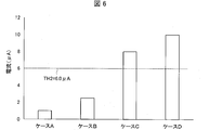
- FIG. 6 is a diagram for explaining the relationship between the degree of wetting shown in FIGS. 5A to 5D and the second threshold value.
- (A) And (b) is a figure for demonstrating the calculation method of average current value Im, respectively. It is a figure which illustrates the flow of the process from the driving
- Embodiment 1 the electrostatic spraying apparatus 100 according to the first embodiment will be described with reference to FIGS.
- the same parts and components are denoted by the same reference numerals. Their names and functions are also the same. Therefore, detailed description thereof will not be repeated.
- the electrostatic spraying apparatus 100 is an apparatus used for spraying aromatic oil, agricultural chemicals, pharmaceuticals, agricultural chemicals, insecticides, air cleaning chemicals, etc., and includes a spray electrode (first electrode) 1 and a reference electrode ( (Second electrode) 2, power supply device 3, and light emitting element (notification unit) 26.
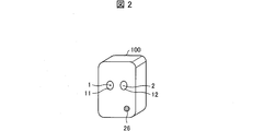
- FIG. 2 is a view for explaining the external appearance of the electrostatic spraying device 100.
- the electrostatic spraying device 100 has a rectangular shape.
- a spray electrode 1 and a reference electrode 2 are disposed on one surface of the apparatus.
- the spray electrode 1 is located in the vicinity of the reference electrode 2.
- An annular opening 11 is formed so as to surround the spray electrode 1, and an annular opening 12 is formed so as to surround the reference electrode 2.
- a voltage is applied between the spray electrode 1 and the reference electrode 2, whereby an electric field is formed between the spray electrode 1 and the reference electrode 2.
- a positively charged droplet is sprayed from the spray electrode 1.
- the reference electrode 2 is negatively charged by ionizing air in the vicinity of the electrode.
- the negatively charged air moves away from the reference electrode 2 due to the electric field formed between the electrodes and the repulsive force between the negatively charged air particles. This movement generates a flow of air (hereinafter also referred to as an ion flow), and positively charged droplets are sprayed in a direction away from the electrostatic spraying device 100 by the ion flow.
- the electrostatic spraying device 100 may have other shapes instead of a rectangular shape. Moreover, the opening 11 and the opening 12 may have a shape different from the annular shape, and the opening dimensions thereof may be adjusted as appropriate.
- the light emitting element 26 may be provided on the surface of the casing of the electrostatic spraying device 100.
- the light emitting element 26 may be a multi-color LED (Light Emitting Diode, light emitting diode) that can selectively emit light of a plurality of predetermined colors. An example of the operation of the light emitting element 26 will be described later.
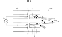
- FIG. 3 is a view for explaining the spray electrode 1 and the reference electrode 2.
- the spray electrode 1 has a conductive conduit such as a metallic capillary (for example, 304 type stainless steel) and a tip 5 that is a tip.
- the spray electrode 1 is electrically connected to the reference electrode 2 via the power supply device 3.
- a spray material (hereinafter referred to as “liquid”) is sprayed from the tip portion 5.
- the spray electrode 1 has an inclined surface 9 that is inclined with respect to the axial center of the spray electrode 1, and the tip is narrower and sharper toward the tip 5.
- the reference electrode 2 is made of a conductive rod such as a metal pin (for example, a 304 type steel pin).
- the spray electrode 1 and the reference electrode 2 are spaced apart from each other at a predetermined interval and are arranged in parallel to each other.
- the spray electrode 1 and the reference electrode 2 are arranged, for example, at an interval of 8 mm from each other.
- the power supply device 3 applies a high voltage between the spray electrode 1 and the reference electrode 2.
- the power supply device 3 applies a high voltage (for example, 3 to 7 kV) between 1 to 30 kV between the spray electrode 1 and the reference electrode 2.
- a high voltage for example, 3 to 7 kV
- an electric field is formed between the electrodes, and an electric dipole is generated inside the dielectric 10.
- the spray electrode 1 is positively charged and the reference electrode 2 is negatively charged (or vice versa).
- negative dipoles are generated on the surface of the dielectric 10 closest to the positive spray electrode 1
- positive dipoles are generated on the surface of the dielectric 10 closest to the negative reference electrode 2. Are emitted by the spray electrode 1 and the reference electrode 2.
- the charge generated in the reference electrode 2 is a charge having a polarity opposite to the polarity of the liquid. Accordingly, the charge of the liquid is balanced by the charge generated at the reference electrode 2. Therefore, the electrostatic spraying device 100 can achieve spray stability based on the principle of charge balance.
- the electrostatic spraying device 100 is configured to spray the liquid from the tip (tip portion 5) of the spray electrode 1 by applying a voltage between the spray electrode 1 and the reference electrode 2. .
- the dielectric 10 is made of a dielectric material such as nylon 6, nylon 11, nylon 12, polypropylene, nylon 66, or a polyacetyl-polytetrafluoroethylene mixture.
- the dielectric 10 supports the spray electrode 1 at the spray electrode mounting portion 6 and supports the reference electrode 2 at the reference electrode mounting portion 7.
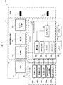
- FIG. 1 is a functional block diagram illustrating a configuration of a main part of the electrostatic spraying apparatus 100.
- the power supply device 3 includes a power supply 21, a high voltage generation device 22, a control circuit (control unit) 24, and a storage unit 29a.
- the power source 21 supplies power necessary for the operation of the electrostatic spraying device 100.
- the power source 21 may be a well-known power source and includes a main power source or one or more batteries.
- the power source 21 is preferably a low voltage power source or a direct current (DC) power source, and is configured by combining one or more dry batteries, for example. The number of batteries depends on the required voltage level and the power consumption of the power source.
- the power source 21 supplies DC power (in other words, DC current and DC voltage) to the oscillator 221 of the high voltage generator 22.
- the high voltage generator 22 includes an oscillator 221, a transformer 222, and a converter circuit 223.
- the oscillator 221 converts DC power (in other words, DC current and DC voltage) into AC power (in other words, AC current and AC voltage).
- a transformer 222 is connected to the oscillator 221.
- the transformer 222 converts the magnitude of the alternating current voltage (or the magnitude of the alternating current).
- a converter circuit 223 is connected to the transformer 222.
- Converter circuit 223 generates a desired voltage and converts AC power (in other words, AC current and AC voltage) into DC power (in other words, DC current and DC voltage).
- the converter circuit 223 includes a charge pump and a rectifier circuit.
- a typical converter circuit is a Cockloft-Walton circuit.
- the control circuit 24 controls each part of the electrostatic spraying apparatus 100 in an integrated manner.
- the function of the control circuit 24 may be realized by a CPU (Central Processing Unit) executing a program stored in the storage unit 29a.
- the storage unit 29a stores various programs executed by the control circuit 24 and data used by the programs.
- the control circuit 24 outputs a PWM (Pulse Width Modulation) signal set to a constant value to the oscillator 221.
- PWM is a method of controlling current and voltage by changing the time (pulse width) for outputting a pulse signal.
- a pulse signal is an electrical signal that repeats ON and OFF, and is represented by, for example, a rectangular wave, and a pulse width that is a voltage output time is represented by a horizontal axis of the rectangular wave.
- a timer that operates at a fixed period is used.
- the position at which the pulse signal is turned on is set in this timer to control the pulse width.
- the ratio that is ON in a certain period is called “duty cycle” (also called “duty ratio”).
- the control circuit 24 includes a microprocessor 241 to cope with various applications.
- the microprocessor 241 may be designed to further adjust the duty cycle of the PWM signal based on the feedback information (ambient environment information) 25.
- the feedback information 25 includes environmental conditions (temperature, humidity, and / or atmospheric pressure), liquid amount, arbitrary settings by the user, and the like.
- the information is given as analog information or digital information and is processed by the microprocessor 241.
- the microprocessor 241 is designed to be able to compensate to improve the quality and stability of the spray by changing either the spray interval, the time to turn on the spray, or the applied voltage based on the input information. May be.
- the feedback information 25 is obtained by a temperature detection element such as a thermistor used for temperature compensation.
- the microprocessor 241 changes the spray interval according to the change in temperature detected by the temperature detection element.
- the spray interval is a spray interval in which the time during which the electrostatic spraying apparatus 100 sprays liquid and the time during which spraying is stopped is one cycle. For example, spraying (on) for 35 seconds (while the power source applies a high voltage between the first electrode and the second electrode), and spraying is stopped (off) for 145 seconds (while the power source is connected to the first electrode)
- the spray interval can be changed by software built in the power source microprocessor 241 and may be controlled to increase from the set point when the temperature rises and to decrease from the set point when the temperature falls.
- the increase and decrease of the spray interval preferably follow a predetermined index determined by the characteristics of the liquid to be sprayed.
- the compensation change amount of the spray interval may be limited so that the spray interval changes only between 0 to 60 ° C. (for example, 10 to 45 ° C.). For this reason, extreme temperatures recorded by the temperature sensing element are considered erroneous and are not considered, and for high and low temperatures, an acceptable but not optimal spray interval is set.
- the measurement result of the temperature sensor 251, the measurement result of the humidity sensor 252, the measurement result of the pressure sensor 253, and the information 254 on the contents of the liquid for example, the liquid storage amount is measured with a level meter Information indicating measurement results), measurement results of the voltage / current sensor 255, and the like.
- the information 254 related to the contents of the liquid may include information indicating the viscosity of the liquid (for example, information indicating the result of measuring the viscosity of the liquid with a viscosity sensor (not shown)).
- ambient environment information information indicating the surrounding environment of the electrostatic spraying apparatus 100
- Feedback information 25 may be used as the surrounding environment information.
- the ambient environment information may include information on at least one of the ambient temperature (temperature), humidity, and atmospheric pressure around the electrostatic spraying device 100.
- the ambient environment information includes (i) information (temperature information) indicating the temperature around the electrostatic spraying device 100, and (ii) information (humidity) indicating the humidity around the electrostatic spraying device 100. Information) is included as an example.
- control circuit 24 is an output port of the microprocessor 241 and outputs a PWM signal to the oscillator 221.
- the spray duty cycle and spray interval may also be controlled via the same PWM output port. While the electrostatic spraying device 100 sprays liquid, a PWM signal is output to the oscillator 221.
- the control circuit 24 controls the output voltage of the high voltage generator 22 by controlling the amplitude, frequency, or duty cycle of the alternating current in the oscillator 221, and the voltage on-off time (or a combination thereof). It may be possible to control.
- the microprocessor 241 includes a current measurement unit 242, a calculation unit 243, a threshold setting unit 244, a determination unit 245, and a notification instruction unit 246.
- a current measurement unit 242 As shown in FIG. 1, the microprocessor 241 includes a current measurement unit 242, a calculation unit 243, a threshold setting unit 244, a determination unit 245, and a notification instruction unit 246.
- a threshold setting unit 244 As shown in FIG. 1, the microprocessor 241 includes a current measurement unit 242, a calculation unit 243, a threshold setting unit 244, a determination unit 245, and a notification instruction unit 246.
- a notification instruction unit 246 As shown in FIG. 1, the microprocessor 241 includes a current measurement unit 242, a calculation unit 243, a threshold setting unit 244, a determination unit 245, and a notification instruction unit 246.
- the current measuring unit 242 measures the value of the current (hereinafter referred to as current I) in the reference electrode 2.
- the current measurement unit 242 may include an arbitrary current measurement device (for example, a current transformer). In the first embodiment, for convenience of explanation, a configuration in which the current measurement unit 242 is provided in the microprocessor 241 is illustrated. However, the current measurement unit 242 may be provided outside the microprocessor 241.
- the calculating unit 243 calculates an average value (an example of a statistical value) of the current I measured by the current measuring unit 242.
- the average value of the current I is referred to as an average current value (statistical current value) Im.
- the average current value Im is an example of a statistical current value described later.
- Embodiment 1 exemplifies a case where the current measurement unit 242 supplies the measured value of the current I to the calculation unit 243 for convenience of explanation.
- the current measurement unit 242 may store the measured value of the current I in the storage unit 29a.
- the calculation unit 243 may acquire the value of the current I stored in the storage unit 29a and calculate the average current value Im.
- the threshold setting unit 244 sets a first threshold TH1 described later.
- the threshold setting unit 244 may set the first threshold TH1 according to the input operation of the user of the electrostatic spraying device 100. Or the 1st threshold value TH1 preset by the manufacturer of the electrostatic spraying apparatus 100 may be stored in the memory
- the threshold setting unit 244 can also set (change) the first threshold TH1 based on the above-described ambient environment information (that is, according to the ambient environment of the electrostatic spraying device 100). A specific example of the first threshold TH1 will be described later.
- the threshold setting unit 244 may further set a second threshold TH2 described later.
- the second threshold TH2 is set as a value larger than the first threshold TH1.
- a specific example of the second threshold TH2 will also be described later.
- the determination unit 245 determines whether or not the value of the current I is normal using the first threshold value TH1. Specifically, the determination unit 245 determines that the value of the current I is normal when the average current value Im is larger than the first threshold value TH1 (when Im> TH1).
- the determination unit 245 determines that the value of the current I is abnormal when the average current value Im is equal to or less than the first threshold value TH1 (when Im ⁇ TH1).
- the case where Im ⁇ TH1 is also referred to as a first abnormal case.
- the determination unit 245 may determine whether or not the value of the current I is normal using the above-described second threshold value TH2. Specifically, the determination unit 245 determines that the value of the current I is normal when the average current value Im is smaller than the second threshold value TH2 (when Im ⁇ TH2).
- the determination unit 245 determines that the value of the current I is abnormal when the average current value Im is equal to or greater than the second threshold value TH2 (when Im ⁇ TH2).
- the case where Im ⁇ TH2 is also referred to as a second abnormal case.
- the determination unit 245 gives determination result information (information indicating whether or not the value of the current I is normal) to the notification instruction unit 246 indicating its own determination result.
- the notification instruction unit 246 controls the operation of the light emitting element 26 in accordance with the determination result information.
- the notification instruction unit 246 may set the light emitting element 26 to the OFF state (non-light emitting state) when the value of the current I is normal.
- the notification instruction unit 246 may cause the light emitting element 26 to emit light of a predetermined color (eg, red light) when the value of the current I is abnormal. Whether or not the value of the current I is normal is notified to the outside of the electrostatic spraying device 100 according to the light emission state of the light emitting element 26.
- a predetermined color eg, red light
- the notification instruction unit 246 changes the notification mode to the outside when the first abnormal case occurs (when Im ⁇ TH1) and when the second abnormal case occurs (when Im ⁇ TH2). You can do it.
- the notification instruction unit 246 may cause the light emitting element 26 to emit red light when the first abnormal case occurs.
- the notification instruction unit 246 may cause the light emitting element 26 to emit light of a color different from the red light (eg, yellow light).
- the notification instruction unit 246 may blink the light emitting element 26 when the second abnormal case occurs. According to said structure, it distinguishes with the alerting
- the light emitting element 26 serves as a “notification unit” that notifies the user that the value of the current I is abnormal.
- the notification unit is the light emitting element 26
- the light emitting element 26 performs visual notification with light to the user.
- the method of notifying that the first abnormal case or the second abnormal case has occurred is not limited to the method using light.
- the electrostatic spraying apparatus 100 may be provided with a speaker (audio output unit), and the speaker may function as a notification unit.
- the notification instruction unit 246 may cause the speaker to output a predetermined sound (eg, alarm sound).
- a vibrator (vibration unit) may be provided in the electrostatic spraying apparatus 100 and the vibrator may function as a notification unit.
- the notification instruction unit 246 may vibrate the vibrator when the value of the current I is abnormal.
- the notification unit may perform notification using a text message. Furthermore, you may combine each above-mentioned alerting
- the notification instruction unit 246 may supply the determination result information other than the notification unit. That is, the notification instruction unit 246 may cause the electrostatic spraying apparatus 100 to perform any operation other than the notification when the value of the current I becomes abnormal.
- the notification instruction unit 246 may temporarily stop the spraying operation of the electrostatic spraying device 100 until the value of the current I returns to normal.
- the first threshold value TH1 will be specifically described with reference to FIG. 4A to 4C are diagrams for explaining the relationship between the ambient environment of the electrostatic spraying device 100 and the first threshold value TH1.
- (a) to (c) of FIG. 4 show the measurement results of the above-described current I when the electrostatic spraying apparatus 100 is sprayed in different surrounding environments (temperature and humidity). It is a graph to show. In the graph, the vertical axis represents current I (unit: ⁇ A), and the horizontal axis represents time (arbitrary unit).
- 4 (a) to 4 (c) are respectively (i) “temperature 25 ° C., relative humidity (RH) 55%”, (ii) “temperature 35 ° C., relative humidity 75%”, and (iii). )
- the measurement result of the current I in the case of “temperature 15 ° C. and relative humidity 35%” is shown.
- the spray performance of the electrostatic spray device 100 is deteriorated and a suitable spray operation cannot be performed.
- the current I decreases to some extent, it is preferable to determine and notify that the value of the current I is abnormal.
- the user can maintain the electrostatic spray device 100 (e.g., clean the reference electrode 2 and remove foreign matter), so that the state in which the spray performance of the electrostatic spray device 100 is reduced can be eliminated. It is.
- a pulse voltage is applied between the spray electrode 1 and the reference electrode 2 at the time of one spraying (one cycle spray interval) in the electrostatic spraying apparatus 100. For this reason, the waveform of the current I flowing through the reference electrode 2 is also pulsed during one spray.
- the current I during each spray is not necessarily uniform. For this reason, even when the operation period of the electrostatic spraying apparatus 100 is not so long, there is a case where the current I becomes relatively small at the time of one spraying.
- the value of the current I is abnormal by using only the instantaneous value of the voltage I. This is because when the adhesion amount of the foreign matter on the reference electrode 2 is not so large and the current I is temporarily reduced, it can be erroneously determined that an abnormality caused by the foreign matter adhesion has occurred.
- the inventors of the present application have come up with a configuration for determining whether or not the value of the current I is abnormal using the above-described average current value Im.
- This average current value Im serves as an index indicating a history of temporal change of the current I over a predetermined time.
- the above configuration conceived by the inventors is to perform the abnormality determination based on the history of the time change of the current I, thereby reducing the possibility of the above-mentioned erroneous determination.
- the first threshold value TH1 is set to 2.0 ⁇ A.
- the numerical value of TH1 of 2.0 ⁇ A is merely an example, and the numerical value of the first threshold value TH1 is not limited to this.
- the first threshold value TH1 may be set to a value larger than 2.0 ⁇ A.
- TH1 may be set to 2.5 ⁇ A.
- the humidity increases as the temperature rises.
- the moisture in the air affects the charge charged around the spray electrode 1.
- a leakage current is likely to occur between the spray electrode 1 and the reference electrode 2.
- the resistance of the spray electrode 1 decreases, and it is difficult to form an electric field suitable for electrostatic spraying between the spray electrode 1 and the reference electrode 2. Thereby, the spray performance of the electrostatic spray apparatus 100 falls.
- FIG. 4B is a measurement result of the current I when the temperature and humidity are higher than in the case of FIG. The tendency for the current I to increase was also confirmed from the graph of FIG.
- the threshold setting unit 244 sets the first threshold TH1 based on the ambient environment information described above.
- the threshold value setting unit 244 may change the value of the first threshold value TH1 using temperature information included in the ambient environment information.
- the threshold setting unit 244 may increase the first threshold TH1 in accordance with an increase in temperature. As an example, as shown in FIGS. 4A and 4B, the threshold value setting unit 244 sets the first threshold value TH1 to “2. It may be increased from “0 ⁇ A to 3.0 ⁇ A”.
- FIG. 4C is a measurement result of the current I when the temperature and humidity are lower than in the case of FIG. Also from the graph of FIG. 4C, the tendency of the current I to decrease was confirmed.
- the threshold value setting unit 244 may decrease the first threshold value TH1 according to a decrease in temperature. As an example, as illustrated in FIGS. 4A and 4C, the threshold value setting unit 244 sets the first threshold value TH1 to “2. It may be reduced to “0 ⁇ A ⁇ 1.5 ⁇ A”.
- the current I increases when the temperature around the electrostatic spraying device 100 is high, and the current I tends to decrease when the temperature is low. it can.
- the threshold value setting unit 244 may increase (i) the first threshold value TH1 in response to an increase in temperature, and (ii) decrease the first threshold value TH1 in response to a decrease in temperature. According to this configuration, the first threshold value TH1 can be increased or decreased according to the increase or decrease of the temperature, so that an abnormality of the electrostatic spray device 100 can be detected more appropriately.
- a predetermined table or conversion formula indicating the correspondence relationship between the temperature and the first threshold value TH1 may be stored in advance in the storage unit 29a by the manufacturer of the electrostatic spraying device 100.
- the threshold setting unit 244 may set the first threshold TH1 according to the temperature using the table or the conversion formula.
- the threshold setting unit 244 may set the first threshold TH1 in the same manner as described above using humidity (humidity information) instead of the temperature (temperature information). Alternatively, the threshold setting unit 244 may set the first threshold TH1 using both the temperature and the humidity.
- the ambient environment information may include information (atmospheric pressure information) indicating the atmospheric pressure around the electrostatic spraying device 100.
- the threshold setting unit 244 may set the first threshold TH1 using the atmospheric pressure information.
- the threshold setting unit 244 may also set the second threshold TH2 described below in the same manner as the first threshold TH1 based on the surrounding environment information. For example, the threshold value setting unit 244 may increase (i) the second threshold value TH2 in response to an increase in temperature and (ii) decrease the second threshold value 2 in response to a decrease in temperature. The threshold setting unit 244 may set at least one of the first threshold TH1 and the second threshold TH2.
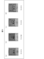
- FIGS. 5A to 5D are diagrams showing the degree of wetting of the surface of the casing of the electrostatic spraying device 100, respectively.
- FIG. 6 is a diagram for explaining the relationship between the degree of wetting shown in FIGS. 5A to 5D and the second threshold value TH2.
- 5A to 5D respectively show (i) the case where the surface of the casing is not wet (case A, No Wetness), and (ii) the case where the surface of the casing is slightly wet (case B). , LightlyWet), (iii) Case where the housing surface is slightly wet (Case C, ModeratelyrateWet), and (iv) Case where the housing surface is particularly wet (Case D, Very Wet) The case is shown.
- FIG. 6 is a graph schematically showing the measurement result of the above-described average current value Im in each of cases A to D. As shown in FIG. 6, it was confirmed that the current I tends to increase as the degree of wetting of the surface of the casing of the electrostatic spray device 100 increases.
- the current I increases and the spraying performance of the electrostatic spraying device 100 decreases.
- the surface of the casing of the electrostatic spraying device 100 is very wet, there is a case where a large amount of liquid sprayed from the tip of the spray electrode 1 adheres to the surface due to the influence of wind.
- the determination unit 245 preferably determines that the value of the current I is abnormal when Im ⁇ TH2 (when the second abnormal case occurs).
- the second threshold value TH2 is set to 6.0 ⁇ A.
- the second threshold TH2 is set with the intention of determining that the value of the current I is abnormal when the degree of wetting is equal to or greater than “Case C”.
- the numerical value of TH2 of 6.0 ⁇ A is merely an example, and the numerical value of the second threshold value TH2 is not limited to this.
- the second threshold TH2 only needs to be set to a value larger than the first threshold TH1.
- the user can be notified that the second abnormal case has occurred.
- the user can maintain the electrostatic spraying device 100 (eg, wipe the surface of the housing and remove the wetting), thereby eliminating the state in which the spraying performance of the electrostatic spraying device 100 has deteriorated. .
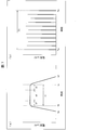
- FIG. 7 is a figure for demonstrating the 1st example (1st method) of the calculation method of average electric current value Im.
- the first method is a method of calculating the average value of the current I at the time of one spraying and setting the calculated result as the average current value Im.
- the first method is a method of calculating the average current value Im in a shorter time range than the second method described below.
- the calculation unit 243 calculates the average current value Im from the average value of the current I during the period when the liquid is sprayed once from the electrostatic spraying device 100.
- the sampling of the current I may be performed at predetermined time intervals (for example, 10 ms).
- time ta is a pulse rising start time
- time tb is a pulse rising end time
- time tc is a pulse falling start time
- time td is a pulse falling end time
- the calculation unit 243 may calculate the average value of the current I over the time t1 in (a) of FIG. 7 (method A1).
- t1 tc ⁇ tb. That is, the current measurement unit 242 excludes (i) the time from time ta to time tb (pulse rise time) and (ii) the time from time tc to time td (pulse fall time).
- An average value of the current I may be calculated.
- the average current value Im can be used as a more accurate index indicating the pulse peak value.
- the calculation unit 243 may calculate the average value of the current I by excluding the time t2 and the time t3 in (a) of FIG. 7 at the time t1 described above (method A2). That is, the current measurement unit 242 may calculate the average value of the current I over the time t4 in FIG.
- t4 t1-t2-t3. Note that the values of t2 and t3 may be set as appropriate.
- the value of the current I may greatly vary with time due to, for example, overshoot or undershoot. Therefore, by calculating the average value of the current I by further excluding the time t2 and the time t3, the average current value Im can be used as a more accurate index indicating the pulse peak value.
- the average current value Im may be calculated by excluding a predetermined time range (time t3) based on the pulse falling start time tc.
- (B) of FIG. 7 is a figure for demonstrating the 2nd example (2nd method) of the calculation method of average electric current value Im.
- the calculation unit 243 calculates the average current value Im from the average value of the current I during the period sprayed from the electrostatic spraying device 100 a predetermined number of times.
- the average value (second average value) of the first average value is further calculated.
- the second average value is a value obtained by averaging the first average value at a time interval corresponding to a predetermined number of sprays.
- the second average value is used as the above-described average current value Im.
- the first method (method A1 or method A2) described above may be used to calculate the first average value in the second method. Or you may perform the statistical process (Example: calculation of a median value or mode) shown in the below-mentioned modification, and may calculate the statistical value (1st statistical value) replaced with a 1st average value. Similarly, a statistical value (second statistical value) instead of the second average value may be calculated.
- FIG. 7B illustrates a case where a total of 11 sprays are performed.
- shaft of (b) of FIG. 7 shows the 1st average value in each spray.
- time Ta indicates the time when the first (first) spray is performed
- time Tb indicates the time when the eleventh (last) spray is performed.
- the calculation unit 243 may calculate the second average value over the time T1 in FIG.
- T1 Ta ⁇ Tb.
- the second method is a method of calculating the average current value Im in a longer time range as compared with the first method described above. Whether to adopt the first method or the second method may be selected by the manufacturer of the electrostatic spraying device 100.
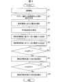
- FIG. 8 is a flowchart illustrating the flow of processes S1 to S10 from the start of operation to notification of abnormality in the electrostatic spraying apparatus 100. Hereinafter, the flow of the processing will be described.
- the electrostatic spraying device 100 when the electrostatic spraying device 100 is powered on (ON), the electrostatic spraying device 100 starts operation (S1).
- the power supply device 3 applies a voltage between the spray electrode 1 and the reference electrode 2 (S2), the electrostatic spray device 100 starts a spray operation.
- the current measuring unit 242 measures the above-described current I (current in the reference electrode 2) (S3). Subsequently, the calculation unit 243 calculates an average value of the current I (average current value Im) (S4, calculation step). As described above, the threshold setting unit 244 sets the first threshold TH1 based on the surrounding environment information (S5). The threshold setting unit 244 further sets the second threshold TH2 based on the surrounding environment information (S6).
- the threshold setting unit 244 does not necessarily need to set the first threshold TH1 and the second threshold TH2 based on the surrounding environment information.
- the threshold setting unit 244 may set one first threshold TH1 and second threshold TH2 independently of the surrounding environment information.
- the determination unit 245 compares the magnitude relationship between the average current value Im and the first threshold value TH1 (S7, determination step). As described above, when the first abnormal case occurs (when Im ⁇ TH1) (YES in S7), the notification instruction unit 246 operates the light emitting element 26 to indicate that the first abnormal case has occurred ( In other words, the fact that the current I is abnormal (too small)) is notified to the outside (S8, notification instruction step).
- Embodiment 1 exemplifies a case where the first abnormal case does not occur (Im> TH1) (NO in S7) and returns to S7. However, when the first abnormal case does not occur, the process may proceed to S9 described below.
- only the second threshold value TH2 may be used to detect only the occurrence of the second abnormal case.
- at least one of (i) detection of the first abnormal case using the first threshold TH1 and (ii) detection of the second abnormal case using the second threshold TH1 may be performed.
- the determination unit 245 compares the magnitude relationship between the average current value Im and the second threshold value TH2 (S9, determination step). As described above, when the second abnormal case occurs (when Im ⁇ TH2) (YES in S9), the notification instruction unit 246 operates the light emitting element 26 to indicate that the second abnormal case has occurred ( In other words, the fact that the current I is abnormal (excessive) is notified to the outside (S10, notification instruction step).
- Embodiment 1 exemplifies the case where the second abnormal case does not occur (when Im ⁇ TH2) (NO in S9) and returns to S9. However, when the second abnormal case does not occur, the process may return to S7 described above.
- the electrostatic spraying device 100 has a current value when the average current value Im is equal to or less than the first threshold value TH1, or (ii) when the average current value Im is equal to or greater than the second threshold value TH2.
- reports to the outside that the electric current I is abnormal are provided.
- the electrostatic spraying apparatus 100 can also detect and notify that the above-described current I (current value in the reference electrode 2) is abnormal. For example, when a foreign substance adheres to the reference electrode 2 and the current I is significantly reduced (when the first abnormal case occurs), the above notification notifies the user of the cleaning of the reference electrode 2 (maintenance of the electrostatic spraying device 100). ). In addition, for example, even when the surface of the case of the electrostatic spraying device 100 becomes so wet that the current I increases remarkably (when the second abnormal case occurs), the above notification notifies the user of cleaning the case ( Maintenance of the electrostatic spraying device 100) can be promoted. Therefore, it can prevent that the spraying performance of the electrostatic spraying apparatus 100 falls.
- the above-described current I current value in the reference electrode 2
- the above notification notifies the user of the cleaning of the reference electrode 2 (maintenance of the electrostatic spraying device 100).
- the above notification notifies the user of cleaning the case ( Maintenance of the electrostatic spraying device 100) can be promoted. Therefore, it
- the electrostatic spraying apparatus 100 it is possible to provide an electrostatic spraying apparatus having a function of detecting an abnormality and notifying the abnormality to the outside.
- the inventors have confirmed that foreign matter adheres to the reference electrode 2 and the current I decreases, and as a result, the spraying performance of the electrostatic spraying device can decrease.
- the inventors have also confirmed that the current I increases when the surface of the casing of the electrostatic spraying device is very wet, and as a result, the spraying performance of the electrostatic spraying device can be reduced.
- the liquid to be sprayed by the electrostatic spraying device 100 is stored in a bottle (not shown) inside the electrostatic spraying device 100.
- the inventors have further found that it is possible to detect whether or not the liquid is present in the bottle based on the average current value Im.
- the inventors have found that when the liquid is not present in the bottle, the average current value Im is reduced as compared with the case where the liquid is present in the bottle. Therefore, for example, the occurrence of the first abnormal mode described above can be used as an indicator that the liquid in the bottle is depleted.
- the bottle is replenished with liquid (or the bottle is filled with liquid). The user can be prompted to replace it with another pre-filled bottle.
- Embodiment 2 will be described with reference to FIGS.
- the electrostatic spray device of the second embodiment is referred to as an electrostatic spray device 100v.
- the electrostatic spraying device 100v and the smartphone (information processing terminal) 200 are combined will be described.
- FIG. 9 is a functional block diagram illustrating a configuration of main parts of the electrostatic spraying device 100v and the smartphone 200 according to the second embodiment.
- the electrostatic spray device 100v removes (i) the calculation unit 243, the threshold setting unit 244, the determination unit 245, and the notification instruction unit 246 from the electrostatic spray device 100 of Embodiment 1.
- the power supply device, the control circuit, and the microprocessor in the electrostatic spraying device 100v are referred to as a power supply device 3v, a control circuit 24v, and a microprocessor 241v, respectively.
- a configuration in which the current measurement unit 242 in the power supply device 3v is provided outside the microprocessor 241v is illustrated for convenience of explanation.
- the smartphone 200 includes a display unit (notification unit) 27, a control unit 290, a storage unit 29b, and a communication unit 248b.
- the control unit 290 includes the calculation unit 243, the threshold setting unit 244, the determination unit 245, and the notification instruction unit 246 of the first embodiment described above.
- each unit for determining and informing that the current I is abnormal is provided in the smartphone 200.
- a mobile phone (smart phone 200) is illustrated as an example of the information processing terminal, but the information processing terminal is not limited to the mobile phone.
- the information processing terminal may be a remote control for the user to remotely operate the electrostatic spraying device 100v, or may be a portable information processing device such as a notebook PC (Personal Computer) or a tablet PC. Good.
- the control unit 290 controls each unit of the smartphone 200 in an integrated manner.
- the function of the control unit 290 may be realized by the CPU executing a program stored in the storage unit 29b.
- the storage unit 29b stores various programs executed by the control unit 290 and data used by the programs.
- the display unit 27 is a member that displays an image, and may be a liquid crystal display, for example. As described below, in the second embodiment, the display unit 27 serves as a notification unit.
- the communication units 248a and 248b are communication interfaces for performing communication between the electrostatic spraying device 100v and the smartphone 200.
- Embodiment 2 the case where the electrostatic spray apparatus 100v and the smart phone 200 perform wireless communication is illustrated. However, communication between the electrostatic spraying device 100v and the smartphone 200 may be performed via a wired line.
- FIG. 10 is a diagram for explaining an example of operations of the electrostatic spraying device 100v and the smartphone 200.
- the notification instruction unit 246 performs the abnormality notification described above by causing the display unit 27 to display a predetermined text message.
- the notification instruction unit 246 may cause the display unit 27 to display a text message MSG “Please clean the pins”. By notifying abnormality by a text message, the user can be prompted to clean the reference electrode 2.
- the notification instruction unit 246 may cause another device to perform abnormality notification via the communication network.
- the notification instructing unit 246 transmits information (e-mail or the like) indicating abnormality notification to an information terminal device (smartphone or the like) owned by the seller of the electrostatic spray device 100v, and notifies the information terminal device of the abnormality. May be allowed.
- FIG. 11 is a sequence diagram illustrating the flow of processes S21 to S27 from the start of operation to notification of abnormality in the second embodiment.
- the electrostatic spraying device 100v performs S21 to S23 (the same processing as S1 to S3 described above).
- the electrostatic spraying device 100v gives the value of the current I measured by the current measuring unit 242 to the calculating unit 243 of the smartphone 200 via the communication units 248a and 248b. And the calculation part 243 calculates the average electric current value Im in S24 (process similar to above-mentioned S4).
- the smartphone 200 performs S25 (processing similar to S4 and S5 described above), S26 (processing similar to S7 and S9 described above), and S27 (processing similar to S8 and S10 described above).
- S25 processing similar to S4 and S5 described above
- S26 processing similar to S7 and S9 described above
- S27 processing similar to S8 and S10 described above.
- the calculation unit 243 may calculate the mode (or median) of the current I over a predetermined time as the index.
- the statistical value as the index calculated by the calculation unit 243 may be referred to as a current statistical value.
- the determination part 245 should just be comprised so that abnormality determination may be performed using an electric current statistical value.
- each functional unit for determining and notifying that the current I is abnormal is provided only in either the electrostatic spraying device or the information processing terminal. did.
- a part of each functional unit may be individually provided in the electrostatic spraying device and the information processing terminal to constitute an integrated abnormality notification device (abnormality notification system) as a whole.
- the abnormality notification device according to one aspect of the present invention (that is, a device that executes the abnormality notification method according to one aspect of the present invention) can be expressed as follows.
- the abnormality notification device is applied to an electrostatic spraying device that sprays liquid from the tip of the first electrode by applying a voltage between the first electrode and the second electrode.
- a calculation unit that calculates a statistical current value indicating a statistical value of a current value in the second electrode; and (i) the statistical current value is equal to or less than a first threshold value of a current value in the second electrode.
- a determination unit that determines that the current value in the second electrode is abnormal when the statistical current value is equal to or greater than a second threshold value of the current value in the second electrode;
- a notification instructing unit for informing the outside that the current value in the second electrode is abnormal when the determination unit determines that the current value in the second electrode is abnormal.
- the information processing terminal according to one embodiment of the present invention can be expressed as follows.
- the information processing terminal further includes a threshold setting unit that sets at least one of the first threshold and the second threshold, and the threshold setting unit determines an ambient environment of the electrostatic spraying device. At least one of the first threshold and the second threshold may be set based on the ambient environment information shown.
- the ambient environment information may include information on at least one of the ambient temperature, humidity, and atmospheric pressure around the electrostatic spraying device.
- the threshold setting unit responds to an increase in the ambient temperature. At least one of the first threshold value and the second threshold value may be increased, and at least one of the first threshold value and the second threshold value may be decreased according to a decrease in the temperature.
- the calculation unit may calculate the statistical current value from a statistical value of a current value in the second electrode during a period in which the liquid is sprayed once.
- the calculation unit may calculate the statistical current value from a statistical value of a current value in the second electrode during a period in which the liquid is sprayed a predetermined number of times.
- the notification instruction unit notifies the outside when the statistical current value is equal to or less than the first threshold and when the statistical current value is equal to or greater than the second threshold.
- the aspect may be changed.
- the notification mode may include at least one of voice, light, vibration, and a text message.
- the electrostatic spraying device is an electrostatic spraying device that sprays liquid from the tip of the first electrode by applying a voltage between the first electrode and the second electrode.
- a calculation unit that calculates a statistical current value indicating a statistical value of a current value in the second electrode, and the second electrode when the statistical current value is equal to or less than a first threshold value of the current value in the second electrode.
- the information processing terminal is connected to an electrostatic spraying device that sprays liquid from the tip of the first electrode by applying a voltage between the first electrode and the second electrode.
- An information processing terminal capable of calculating a statistical current value indicating a statistical value of a current value in the second electrode, and the statistical current value being equal to or less than a first threshold value of the current value in the second electrode.
- the determination unit determines that the current value in the second electrode is abnormal, and the determination unit determines that the current value in the second electrode is abnormal when the determination unit determines that the current value in the second electrode is abnormal.
- a notification instructing unit for informing the outside of the fact that there is an abnormality.
- the abnormality notification method is applied to an electrostatic spraying device that sprays liquid from the tip of the first electrode by applying a voltage between the first electrode and the second electrode.
- a notification instructing step for informing the outside that it is abnormal.
- the electrostatic spraying device is an electrostatic spraying device that sprays liquid from the tip of the first electrode by applying a voltage between the first electrode and the second electrode.
- a calculating unit that calculates a statistical current value indicating a statistical value of a current value in the second electrode, and the second electrode when the statistical current value is equal to or greater than a second threshold value of the current value in the second electrode.
- the information processing terminal is connected to an electrostatic spraying device that sprays liquid from the tip of the first electrode by applying a voltage between the first electrode and the second electrode.
- a calculation unit that calculates a statistical current value indicating a statistical value of a current value in the second electrode; and the statistical current value is equal to or greater than a second threshold value of the current value in the second electrode.
- the determination unit determines that the current value in the second electrode is abnormal, and the determination unit determines that the current value in the second electrode is abnormal when the determination unit determines that the current value in the second electrode is abnormal.
- a notification instructing unit for informing the outside of the fact that there is an abnormality.
- the abnormality notification method is applied to an electrostatic spraying device that sprays liquid from the tip of the first electrode by applying a voltage between the first electrode and the second electrode.
- a notification instructing step for informing the outside that it is abnormal.
- the abnormality of the electrostatic spraying device may be determined based on the value of the voltage applied between the spray electrode 1 and the reference electrode 2.
- the value of the voltage applied between the spray electrode 1 and the reference electrode 2 may vary depending on the variation of the electric field.
- a voltage measurement unit that measures a voltage applied between the spray electrode 1 and the reference electrode 2 may be provided instead of the current measurement unit 242. Also in this case, the abnormality of the electrostatic spraying device can be determined based on the measurement result of the voltage measuring unit.
- control blocks (particularly the microprocessors 241 and 241v and the control unit 290) of the electrostatic spraying apparatuses 100 and 100v and the smartphone 200 may be realized by a logic circuit (hardware) formed in an integrated circuit (IC chip) or the like. However, it may be realized by software using a CPU (Central Processing Unit).
- a logic circuit hardware
- IC chip integrated circuit
- CPU Central Processing Unit
- the electrostatic spraying apparatus 100 / 100v and the smartphone 200 have a CPU that executes instructions of a program that is software that realizes each function, and the program and various data are recorded so as to be readable by a computer (or CPU).
- a ROM (Read Only Memory) or a storage device (these are referred to as “recording media”), a RAM (Random Access Memory) for expanding the program, and the like are provided.
- the objective of this invention is achieved when a computer (or CPU) reads the said program from the said recording medium and runs it.
- a “non-temporary tangible medium” such as a tape, a disk, a card, a semiconductor memory, a programmable logic circuit, or the like can be used.
- the program may be supplied to the computer via an arbitrary transmission medium (such as a communication network or a broadcast wave) that can transmit the program.
- an arbitrary transmission medium such as a communication network or a broadcast wave
- one embodiment of the present invention can also be realized in the form of a data signal embedded in a carrier wave, in which the program is embodied by electronic transmission.
- the electrostatic spraying device is an electrostatic spraying device that sprays a liquid from the tip of the first electrode by applying a voltage between the first electrode and the second electrode, A calculation unit that calculates a statistical current value indicating a statistical value of a current value in the second electrode; and (ii) if the statistical current value is equal to or less than a first threshold value of the current value in the second electrode, or (ii) ) When the statistical current value is greater than or equal to a second threshold value of the current value at the second electrode, a determination unit that determines that the current value at the second electrode is abnormal, and the determination unit at the second electrode And a notification instructing unit that notifies the outside that the current value in the second electrode is abnormal when it is determined that the current value is abnormal.
- the current value (the above-described current I) in the second electrode decreases. Further, for example, when the surface of the casing of the electrostatic spraying device is very wet, the current value in the second electrode increases. When such a decrease or increase in current value occurs, the spray performance of the electrostatic spray device may be reduced.
- the above configuration it is possible to detect and notify at least one of (i) a decrease in the current value at the second electrode and (ii) an increase in the current value at the second electrode. That is, it is possible to detect abnormality of the electrostatic spraying device. Moreover, when abnormality of an electrostatic spraying apparatus generate
- an electrostatic spraying apparatus having a function of detecting an abnormality and notifying the abnormality to the outside.
- the electrostatic spraying apparatus further includes a threshold setting unit that sets at least one of the first threshold and the second threshold in the aspect 1, and the threshold setting unit includes the electrostatic You may set at least any one of the said 1st threshold value and the said 2nd threshold value based on the surrounding environment information which shows the surrounding environment of a spraying apparatus.
- At least one of the first threshold value and the second threshold value can be set according to the surrounding environment of the electrostatic spraying device.
- the ambient environment information includes information on at least one of the ambient temperature, humidity, and atmospheric pressure around the electrostatic spraying device. Also good.
- At least one of the first threshold value and the second threshold value can be set according to at least one of the ambient temperature, humidity, and atmospheric pressure around the electrostatic spraying device.
- the threshold setting unit is According to an increase in temperature, at least one of the first threshold and the second threshold may be increased, and according to a decrease in the temperature, at least one of the first threshold and the second threshold may be decreased. Good.
- At least one of the first threshold value and the second threshold value can be increased / decreased according to the increase / decrease in the air temperature, so that it is possible to detect an abnormality of the electrostatic spraying device more appropriately.
- the electrostatic spraying device is the electrostatic spraying device according to any one of the above aspects 1 to 4, wherein the calculation unit is a statistical value of a current value in the second electrode during a period in which the liquid is sprayed once.
- the statistical current value may be calculated from
- the electrostatic spraying device is the electrostatic spraying device according to any one of the above aspects 1 to 4, wherein the calculator calculates the current value in the second electrode during a period in which the liquid is sprayed a predetermined number of times.
- the statistical current value may be calculated from the value.
- the electrostatic spraying device is the electrostatic spraying device according to any one of the aspects 1 to 6, wherein the notification instruction unit is configured such that the statistical current value is not more than the first threshold value and the statistical current value is You may change the alerting
- the first abnormal case a case where the statistical current value is equal to or smaller than the first threshold value
- the second abnormal case a case where the statistical current value is equal to or larger than the second threshold value
- the notification aspect may include at least one of voice, light, vibration, and a text message.
- the information processing terminal can be connected to an electrostatic spraying device that sprays liquid from the tip of the first electrode by applying a voltage between the first electrode and the second electrode.
- An information processing terminal that calculates a statistical current value indicating a statistical value of a current value in the second electrode; and (i) the statistical current value is equal to or less than a first threshold value of a current value in the second electrode.
- a determination unit that determines that the current value in the second electrode is abnormal when the statistical current value is equal to or greater than a second threshold value of the current value in the second electrode;
- a notification instructing unit for informing the outside that the current value in the second electrode is abnormal when the unit determines that the current value in the second electrode is abnormal.
- the abnormality notification method is applied to an electrostatic spraying device that sprays liquid from the tip of the first electrode by applying a voltage between the first electrode and the second electrode.
- a notification instruction step for informing the outside that the current value in the second electrode is abnormal when it is determined that the current value in the second electrode is abnormal.
- the information processing terminal according to each aspect of the present invention may be realized by a computer.
- the information processing terminal is operated on each computer by causing the computer to operate as each unit (software element) included in the information processing terminal.
- the control program for the information processing terminal to be realized and the computer-readable recording medium on which the control program is recorded also fall within the scope of the present invention.
- Spray electrode (first electrode) 2 Reference electrode (second electrode) 25 Feedback information (Ambient environment information) 100, 100v electrostatic spraying device 200 Smartphone (information processing terminal) 243 calculation unit 244 threshold setting unit 245 determination unit 246 notification instruction unit I current Im average current value (statistical current value) TH1 first threshold TH2 second threshold
Abstract
Provided is an electrostatic atomization device equipped with a function for detecting an abnormality and notifying the outside of said abnormality. An electrostatic atomization device (100) includes: a calculation unit (243) that calculates a statistical current value indicating the statistical value of a current value at a reference electrode (2); a threshold setting unit (244) that sets a first threshold for said current value; a determination unit (245) that, (i) if the statistical average current value is equal to or less than the first threshold or (ii) if the statistical current value is equal to or greater than a second threshold for the current value at said second electrode, determines that the current value at the reference electrode (2) is abnormal; and a notification instruction unit (246) that, if the determination unit (245) determines that the current value at the reference electrode (2) is abnormal, notifies the outside of said abnormal current value.
Description
本発明は、静電噴霧装置等に関する。
The present invention relates to an electrostatic spraying device and the like.
従来から、容器内の液体をノズルから噴射する噴霧装置が幅広い分野に適用されている。この種の噴霧装置として、電気流体力学(EHD:Electro Hydrodynamics)により液体を霧化して噴霧する静電噴霧装置が知られている。この静電噴霧装置は、ノズルの先端近傍に電場を形成し、その電場を利用してノズルの先端の液体を霧化して噴射するものである。そのような静電噴霧装置を開示する文献として、特許文献1が知られている。
Conventionally, a spraying apparatus that ejects liquid in a container from a nozzle has been applied to a wide range of fields. As this type of spraying device, an electrostatic spraying device that atomizes and sprays a liquid by electrohydrodynamics (EHD) is known. This electrostatic spraying device forms an electric field in the vicinity of the tip of the nozzle, and uses the electric field to atomize and spray the liquid at the tip of the nozzle. Patent Document 1 is known as a document disclosing such an electrostatic spraying device.
特許文献1の静電噴霧装置は電流フィードバック回路を備え、電流フィードバック回路は、基準電極の電流値を測定する。特許文献1の静電噴霧装置は電荷平衡されるため、この電流値が測定され、参照されることにより、スプレー電極での電流が正確に把握される。そして、特許文献1の静電噴霧装置は、スプレー電極での電流値を一定の値に保つフィードバック制御を用いることにより噴霧の安定性を高めている。
The electrostatic spraying device of Patent Document 1 includes a current feedback circuit, and the current feedback circuit measures the current value of the reference electrode. Since the electrostatic spraying device of Patent Document 1 is charge-balanced, the current value is measured and referenced to accurately grasp the current at the spray electrode. And the electrostatic spraying apparatus of patent document 1 is improving the stability of spraying using the feedback control which maintains the electric current value in a spray electrode at a constant value.
しかしながら、特許文献1の静電噴霧装置が長期間使用された場合、異物(例:空気中の埃、噴霧する液体に由来する汚れ、基準電極(第2電極)の腐食によって生じた生成物、基準電極に発生した錆)が基準電極に付着し、当該基準電極における電流値が低下することがある。その場合、上記静電噴霧装置の噴霧性能が低下することが考えられる。
However, when the electrostatic spray device of Patent Document 1 is used for a long period of time, foreign matter (eg, dust in the air, dirt derived from the liquid to be sprayed, products generated by corrosion of the reference electrode (second electrode), Rust generated at the reference electrode) may adhere to the reference electrode, and the current value at the reference electrode may decrease. In that case, it is conceivable that the spraying performance of the electrostatic spraying device is lowered.
また、静電噴霧装置が長期間使用された場合、例えば静電噴霧装置の筐体の表面の濡れが大きくなり、基準電極における電流値が増加することがある。この場合にも、静電噴霧装置の噴霧性能が低下することが考えられる。
Also, when the electrostatic spraying device is used for a long period of time, for example, the surface of the casing of the electrostatic spraying device becomes so wet that the current value at the reference electrode may increase. Also in this case, it is conceivable that the spraying performance of the electrostatic spraying device is lowered.
しかし、特許文献1の静電噴霧装置には、基準電極における電流値の異常を検知し、外部へ報知させる機能(仕組み)は搭載されていない。
However, the electrostatic spraying device of Patent Document 1 is not equipped with a function (mechanism) for detecting an abnormality in the current value at the reference electrode and notifying the outside.
本発明の一態様は、異常を検知し、当該異常を外部に報知させる機能を備えた静電噴霧装置を提供することにある。
An aspect of the present invention is to provide an electrostatic spraying device having a function of detecting an abnormality and notifying the abnormality to the outside.
本発明の一態様に係る静電噴霧装置は、第1電極と第2電極との間に電圧を印加することにより、当該第1電極の先端から液体を噴霧する静電噴霧装置であって、上記第2電極における電流値の統計値を示す統計電流値を算出する算出部と、(i)上記統計電流値が上記第2電極における電流値の第1閾値以下である場合、または、(ii)上記統計電流値が上記第2電極における電流値の第2閾値以上である場合に、上記第2電極における電流値が異常であると判定する判定部と、上記判定部が上記第2電極における電流値は異常であると判定した場合に、当該第2電極における電流値が異常である旨を外部に報知させる報知指示部と、を備える。
An electrostatic spraying apparatus according to an aspect of the present invention is an electrostatic spraying apparatus that sprays a liquid from the tip of the first electrode by applying a voltage between the first electrode and the second electrode, A calculation unit that calculates a statistical current value indicating a statistical value of a current value in the second electrode; and (ii) if the statistical current value is equal to or less than a first threshold value of the current value in the second electrode, or (ii) ) When the statistical current value is greater than or equal to a second threshold value of the current value at the second electrode, a determination unit that determines that the current value at the second electrode is abnormal, and the determination unit at the second electrode And a notification instructing unit that notifies the outside that the current value in the second electrode is abnormal when it is determined that the current value is abnormal.
また、本発明の一態様に係る情報処理端末は、第1電極と第2電極との間に電圧を印加することにより、当該第1電極の先端から液体を噴霧する静電噴霧装置と通信接続可能な情報処理端末であって、上記第2電極における電流値の統計値を示す統計電流値を算出する算出部と、(i)上記統計電流値が上記第2電極における電流値の第1閾値以下である場合、または、(ii)上記統計電流値が上記第2電極における電流値の第2閾値以上である場合に、上記第2電極における電流値が異常であると判定する判定部と、上記判定部が上記第2電極における電流値は異常であると判定した場合に、当該第2電極における電流値が異常である旨を外部に報知させる報知指示部と、を備える。
The information processing terminal according to one aspect of the present invention is connected to an electrostatic spraying device that sprays liquid from the tip of the first electrode by applying a voltage between the first electrode and the second electrode. A calculation unit for calculating a statistical current value indicating a statistical value of a current value in the second electrode; and (i) a first threshold value of the current value in the second electrode. Or (ii) a determination unit that determines that the current value in the second electrode is abnormal when the statistical current value is equal to or greater than a second threshold value of the current value in the second electrode; And a notification instructing unit for informing the outside that the current value in the second electrode is abnormal when the determination unit determines that the current value in the second electrode is abnormal.
また、本発明の一態様に係る異常報知方法は、第1電極と第2電極との間に電圧を印加することにより、当該第1電極の先端から液体を噴霧する静電噴霧装置に適用される異常報知方法であって、上記第2電極における電流値の統計値を示す統計電流値を算出する算出ステップと、(i)上記統計電流値が上記第2電極における電流値の第1閾値以下である場合、または、(ii)上記統計電流値が上記第2電極における電流値の第2閾値以上である場合に、上記第2電極における電流値が異常であると判定する判定ステップと、上記判定ステップにおいて上記第2電極における電流値は異常であると判定された場合に、当該第2電極における電流値が異常である旨を外部に報知させる報知指示ステップと、を含む。
The abnormality notification method according to one aspect of the present invention is applied to an electrostatic spraying device that sprays liquid from the tip of the first electrode by applying a voltage between the first electrode and the second electrode. A calculation step of calculating a statistical current value indicating a statistical value of a current value in the second electrode, and (i) the statistical current value is equal to or less than a first threshold value of a current value in the second electrode. Or (ii) a determination step of determining that the current value at the second electrode is abnormal when the statistical current value is equal to or greater than a second threshold value of the current value at the second electrode; And a notification instruction step of notifying the outside that the current value in the second electrode is abnormal when it is determined in the determination step that the current value in the second electrode is abnormal.
本発明の一態様に係る静電噴霧装置によれば、異常を検知し、当該異常を外部に報知させる機能を備えた静電噴霧装置を提供することが可能となる。
According to the electrostatic spraying device according to one aspect of the present invention, it is possible to provide an electrostatic spraying device having a function of detecting an abnormality and notifying the abnormality to the outside.
また、本発明の一態様に係る情報処理端末および異常報知方法によっても、同様の効果を奏する。
In addition, the information processing terminal and the abnormality notification method according to one aspect of the present invention also have the same effect.
〔実施形態1〕
以下、図1~図8を参照し、実施形態1に係る静電噴霧装置100について説明する。以下の説明では、同一の部品および構成要素には同一の符号を付している。それらの名称および機能も同じである。従って、それらについての詳細な説明は繰り返さない。Embodiment 1
Hereinafter, theelectrostatic spraying apparatus 100 according to the first embodiment will be described with reference to FIGS. In the following description, the same parts and components are denoted by the same reference numerals. Their names and functions are also the same. Therefore, detailed description thereof will not be repeated.
以下、図1~図8を参照し、実施形態1に係る静電噴霧装置100について説明する。以下の説明では、同一の部品および構成要素には同一の符号を付している。それらの名称および機能も同じである。従って、それらについての詳細な説明は繰り返さない。
Hereinafter, the
〔静電噴霧装置100〕
静電噴霧装置100は、芳香油、農産物用化学物質、医薬品、農薬、殺虫剤、空気清浄化薬剤等の噴霧等に用いられる装置であり、スプレー電極(第1電極)1と、基準電極(第2電極)2と、電源装置3と、発光素子(報知部)26とを備える。 [Electrostatic spray device 100]
Theelectrostatic spraying apparatus 100 is an apparatus used for spraying aromatic oil, agricultural chemicals, pharmaceuticals, agricultural chemicals, insecticides, air cleaning chemicals, etc., and includes a spray electrode (first electrode) 1 and a reference electrode ( (Second electrode) 2, power supply device 3, and light emitting element (notification unit) 26.
静電噴霧装置100は、芳香油、農産物用化学物質、医薬品、農薬、殺虫剤、空気清浄化薬剤等の噴霧等に用いられる装置であり、スプレー電極(第1電極)1と、基準電極(第2電極)2と、電源装置3と、発光素子(報知部)26とを備える。 [Electrostatic spray device 100]
The
まず、静電噴霧装置100の外観を図2により説明する。図2は、静電噴霧装置100の外観を説明するための図である。
First, the external appearance of the electrostatic spraying device 100 will be described with reference to FIG. FIG. 2 is a view for explaining the external appearance of the electrostatic spraying device 100.
図示するように、静電噴霧装置100は、直方形状である。その装置の一面に、スプレー電極1および基準電極2が配設されている。スプレー電極1は、基準電極2の近傍に位置する。また、スプレー電極1を取り囲むように環状の開口11が、基準電極2を取り囲むように環状の開口12が、それぞれ形成されている。
As illustrated, the electrostatic spraying device 100 has a rectangular shape. A spray electrode 1 and a reference electrode 2 are disposed on one surface of the apparatus. The spray electrode 1 is located in the vicinity of the reference electrode 2. An annular opening 11 is formed so as to surround the spray electrode 1, and an annular opening 12 is formed so as to surround the reference electrode 2.
スプレー電極1と基準電極2との間には電圧が印加され、それによりスプレー電極1と基準電極2との間に電場が形成される。スプレー電極1からは正帯電した液滴が噴霧される。基準電極2は、電極近傍の空気をイオン化して負帯電させる。そして、負帯電した空気は、電極間に形成された電場と負帯電された空気粒子間の反発力とによって基準電極2から遠ざかる動きをする。この動きが空気の流れ(以下、イオン流と称する場合もある)を生み、このイオン流によって正帯電した液滴が静電噴霧装置100から離れる方向へと噴霧される。
A voltage is applied between the spray electrode 1 and the reference electrode 2, whereby an electric field is formed between the spray electrode 1 and the reference electrode 2. A positively charged droplet is sprayed from the spray electrode 1. The reference electrode 2 is negatively charged by ionizing air in the vicinity of the electrode. The negatively charged air moves away from the reference electrode 2 due to the electric field formed between the electrodes and the repulsive force between the negatively charged air particles. This movement generates a flow of air (hereinafter also referred to as an ion flow), and positively charged droplets are sprayed in a direction away from the electrostatic spraying device 100 by the ion flow.
静電噴霧装置100は、直方形状ではなく、他の形状であってもよい。また、開口11、および開口12は、環状とは異なる形状であってよく、その開口寸法も適宜調整されうる。
The electrostatic spraying device 100 may have other shapes instead of a rectangular shape. Moreover, the opening 11 and the opening 12 may have a shape different from the annular shape, and the opening dimensions thereof may be adjusted as appropriate.
また、図2に示されるように、発光素子26は、静電噴霧装置100の筐体の表面に設けられていてよい。一例として、発光素子26は、所定の複数の色の光を選択的に出射できる多色LED(Light Emitting Diode,発光ダイオード)であってよい。発光素子26の動作の一例については後述する。
Further, as shown in FIG. 2, the light emitting element 26 may be provided on the surface of the casing of the electrostatic spraying device 100. As an example, the light emitting element 26 may be a multi-color LED (Light Emitting Diode, light emitting diode) that can selectively emit light of a plurality of predetermined colors. An example of the operation of the light emitting element 26 will be described later.
〔スプレー電極1、基準電極2〕
スプレー電極1、および基準電極2を図3により説明する。図3は、スプレー電極1、および基準電極2を説明するための図である。 [Spray electrode 1, reference electrode 2]
Thespray electrode 1 and the reference electrode 2 will be described with reference to FIG. FIG. 3 is a view for explaining the spray electrode 1 and the reference electrode 2.
スプレー電極1、および基準電極2を図3により説明する。図3は、スプレー電極1、および基準電極2を説明するための図である。 [
The
スプレー電極1は、金属性キャピラリ(例えば、304型ステンレス鋼など)等の導電性導管と、先端部である先端部5とを有する。スプレー電極1は、電源装置3を介して基準電極2と電気的に接続される。先端部5からは噴霧物質(以下、「液体」と称する)が噴霧される。スプレー電極1は、スプレー電極1の軸心に対して傾斜する傾斜面9を有し、先端部5に向かうほど先端が細く、尖った形状である。
The spray electrode 1 has a conductive conduit such as a metallic capillary (for example, 304 type stainless steel) and a tip 5 that is a tip. The spray electrode 1 is electrically connected to the reference electrode 2 via the power supply device 3. A spray material (hereinafter referred to as “liquid”) is sprayed from the tip portion 5. The spray electrode 1 has an inclined surface 9 that is inclined with respect to the axial center of the spray electrode 1, and the tip is narrower and sharper toward the tip 5.
基準電極2は、金属ピン(例えば、304型スチールピンなど)等の導電性ロッドからなる。スプレー電極1および基準電極2は、一定の間隔をあけて離間し、互いに平行に配置されている。スプレー電極1および基準電極2は、例えば、互いに8mmの間隔をあけて配置される。
The reference electrode 2 is made of a conductive rod such as a metal pin (for example, a 304 type steel pin). The spray electrode 1 and the reference electrode 2 are spaced apart from each other at a predetermined interval and are arranged in parallel to each other. The spray electrode 1 and the reference electrode 2 are arranged, for example, at an interval of 8 mm from each other.
電源装置3は、スプレー電極1と基準電極2との間に高電圧を印加する。例えば、電源装置3は、スプレー電極1と基準電極2との間に1~30kVの間の高電圧(例えば、3~7kV)を印加する。高電圧が印加されると電極間に電場が形成され、誘電体10の内部に電気双極子が生じる。このとき、スプレー電極1は正に帯電し、基準電極2は負に帯電する(その逆でもよい)。そして、負の双極子が正のスプレー電極1に最も近い誘電体10の表面に生じ、正の双極子が負の基準電極2に最も近い誘電体10の表面に生じ、帯電したガスおよび物質種が、スプレー電極1および基準電極2によって放出される。ここで、上述したように、基準電極2において生成される電荷は、液体の極性とは逆の極性の電荷である。従って、液体の電荷は、基準電極2において生成される電荷によって平衡化される。それゆえ、静電噴霧装置100は、電荷平衡の原理に基づき、噴霧の安定性を図ることができる。
The power supply device 3 applies a high voltage between the spray electrode 1 and the reference electrode 2. For example, the power supply device 3 applies a high voltage (for example, 3 to 7 kV) between 1 to 30 kV between the spray electrode 1 and the reference electrode 2. When a high voltage is applied, an electric field is formed between the electrodes, and an electric dipole is generated inside the dielectric 10. At this time, the spray electrode 1 is positively charged and the reference electrode 2 is negatively charged (or vice versa). Then, negative dipoles are generated on the surface of the dielectric 10 closest to the positive spray electrode 1, and positive dipoles are generated on the surface of the dielectric 10 closest to the negative reference electrode 2. Are emitted by the spray electrode 1 and the reference electrode 2. Here, as described above, the charge generated in the reference electrode 2 is a charge having a polarity opposite to the polarity of the liquid. Accordingly, the charge of the liquid is balanced by the charge generated at the reference electrode 2. Therefore, the electrostatic spraying device 100 can achieve spray stability based on the principle of charge balance.
このように、静電噴霧装置100は、スプレー電極1と基準電極2との間に電圧を印加することにより、スプレー電極1の先端(先端部5)から液体を噴霧できるように構成されている。
As described above, the electrostatic spraying device 100 is configured to spray the liquid from the tip (tip portion 5) of the spray electrode 1 by applying a voltage between the spray electrode 1 and the reference electrode 2. .
誘電体10は、例えばナイロン6、ナイロン11、ナイロン12、ポリプロピレン、ナイロン66またはポリアセチル-ポリテトラフルオロエチレン混合物などの誘電体材料からなる。誘電体10は、スプレー電極1をスプレー電極取付部6において支持し、基準電極2を基準電極取付部7において支持する。
The dielectric 10 is made of a dielectric material such as nylon 6, nylon 11, nylon 12, polypropylene, nylon 66, or a polyacetyl-polytetrafluoroethylene mixture. The dielectric 10 supports the spray electrode 1 at the spray electrode mounting portion 6 and supports the reference electrode 2 at the reference electrode mounting portion 7.
〔電源装置3〕
電源装置3を図1により説明する。図1は、静電噴霧装置100の要部の構成を示す機能ブロック図である。 [Power supply 3]
Thepower supply device 3 will be described with reference to FIG. FIG. 1 is a functional block diagram illustrating a configuration of a main part of the electrostatic spraying apparatus 100.
電源装置3を図1により説明する。図1は、静電噴霧装置100の要部の構成を示す機能ブロック図である。 [Power supply 3]
The
電源装置3は、電源21と、高電圧発生装置22と、制御回路(制御部)24と、記憶部29aとを備える。
The power supply device 3 includes a power supply 21, a high voltage generation device 22, a control circuit (control unit) 24, and a storage unit 29a.
電源21は、静電噴霧装置100の運転に必要な電源を供給する。電源21は、周知の電源であってよく、主電源または1つ以上のバッテリーを含む。電源21は、低電圧電源、直流(DC)電源が好ましく、例えば、1つ以上の乾電池を組み合わせて構成される。電池の個数は、必要な電圧レベルと電源の消費電力とによって決まる。電源21は、高電圧発生装置22の発振器221に直流電力(換言すれば、直流電流および直流電圧)を供給する。
The power source 21 supplies power necessary for the operation of the electrostatic spraying device 100. The power source 21 may be a well-known power source and includes a main power source or one or more batteries. The power source 21 is preferably a low voltage power source or a direct current (DC) power source, and is configured by combining one or more dry batteries, for example. The number of batteries depends on the required voltage level and the power consumption of the power source. The power source 21 supplies DC power (in other words, DC current and DC voltage) to the oscillator 221 of the high voltage generator 22.
高電圧発生装置22は、発振器221と、変圧器222と、コンバータ回路223とを備える。発振器221は、直流電力(換言すれば、直流電流および直流電圧)を交流電力(換言すれば、交流電流および交流電圧)に変換する。発振器221には変圧器222が接続される。変圧器222は、交流電流の電圧の大きさ(または交流電流の大きさ)を変換する。変圧器222にはコンバータ回路223が接続される。コンバータ回路223は、所望の電圧を生成し、交流電力(換言すれば、交流電流および交流電圧)を直流電力(換言すれば、直流電流および直流電圧)に変換する。通常、コンバータ回路223は、チャージポンプと整流回路とを備える。典型的なコンバータ回路は、コックロフト・ウォルトン回路である。
The high voltage generator 22 includes an oscillator 221, a transformer 222, and a converter circuit 223. The oscillator 221 converts DC power (in other words, DC current and DC voltage) into AC power (in other words, AC current and AC voltage). A transformer 222 is connected to the oscillator 221. The transformer 222 converts the magnitude of the alternating current voltage (or the magnitude of the alternating current). A converter circuit 223 is connected to the transformer 222. Converter circuit 223 generates a desired voltage and converts AC power (in other words, AC current and AC voltage) into DC power (in other words, DC current and DC voltage). Usually, the converter circuit 223 includes a charge pump and a rectifier circuit. A typical converter circuit is a Cockloft-Walton circuit.
制御回路24は、静電噴霧装置100の各部を統括的に制御する。制御回路24の機能は、記憶部29aに記憶されたプログラムを、CPU(Central Processing Unit)が実行することで実現されてよい。記憶部29aは、制御回路24が実行する各種のプログラム、および当該プログラムによって使用されるデータを格納する。
The control circuit 24 controls each part of the electrostatic spraying apparatus 100 in an integrated manner. The function of the control circuit 24 may be realized by a CPU (Central Processing Unit) executing a program stored in the storage unit 29a. The storage unit 29a stores various programs executed by the control circuit 24 and data used by the programs.
制御回路24は、一定の値に設定されたPWM(Pulse Width Modulation,パルス幅変調)信号を発振器221に出力する。PWMとは、パルス信号を出力する時間(パルス幅)を変更することで電流や電圧を制御する方式のことである。パルス信号とは、ON、OFFを繰り返す電気信号のことであり、例えば、矩形波で表され、電圧の出力時間であるパルス幅は矩形波の横軸で表される。
The control circuit 24 outputs a PWM (Pulse Width Modulation) signal set to a constant value to the oscillator 221. PWM is a method of controlling current and voltage by changing the time (pulse width) for outputting a pulse signal. A pulse signal is an electrical signal that repeats ON and OFF, and is represented by, for example, a rectangular wave, and a pulse width that is a voltage output time is represented by a horizontal axis of the rectangular wave.
PWM方式では、一定周期で動作するタイマを利用する。このタイマにパルス信号をONにする位置を設定してパルス幅を制御する。一定周期の中でONにしている比率のことを「デューティーサイクル」(「デューティー比」とも称される)と言う。
In the PWM method, a timer that operates at a fixed period is used. The position at which the pulse signal is turned on is set in this timer to control the pulse width. The ratio that is ON in a certain period is called “duty cycle” (also called “duty ratio”).
制御回路24は、様々な用途に対応するために、マイクロプロセッサ241を備える。マイクロプロセッサ241は、フィードバック情報(周囲環境情報)25に基づいて、PWM信号のデューティーサイクルをさらに調整できるように設計されていてもよい。
The control circuit 24 includes a microprocessor 241 to cope with various applications. The microprocessor 241 may be designed to further adjust the duty cycle of the PWM signal based on the feedback information (ambient environment information) 25.
フィードバック情報25には、環境条件(気温、湿度、および/または、大気圧)、液体量、ユーザによる任意の設定などが含まれる。その情報は、アナログ情報またはデジタル情報として与えられ、マイクロプロセッサ241により処理される。マイクロプロセッサ241は、入力情報に基づいて、スプレー間隔、スプレーをオンにする時間、または印加電圧の何れかを変更することでスプレーの品質および安定性を高めるための補償を行うことも可能に設計されていてもよい。
The feedback information 25 includes environmental conditions (temperature, humidity, and / or atmospheric pressure), liquid amount, arbitrary settings by the user, and the like. The information is given as analog information or digital information and is processed by the microprocessor 241. The microprocessor 241 is designed to be able to compensate to improve the quality and stability of the spray by changing either the spray interval, the time to turn on the spray, or the applied voltage based on the input information. May be.
一例として、フィードバック情報25は、温度補償のために使用されるサーミスタなどの温度検知素子よって得られる。このとき、マイクロプロセッサ241は、温度検知素子により検知された温度の変化に従ってスプレー間隔を変化させる。スプレー間隔は、静電噴霧装置100が液体を噴霧する時間および噴霧を停止する時間を一サイクルとする噴霧間隔である。例えば、35秒間噴霧(オン)とし(その間、電源は第1電極と第2電極との間に高電圧を印加する)、145秒間噴霧停止(オフ)とする(その間、電源は第1電極と第2電極との間に高電圧を印加しない)周期的なスプレー間隔の場合を考える。この場合、スプレー間隔は、35秒+145秒=180秒である。
As an example, the feedback information 25 is obtained by a temperature detection element such as a thermistor used for temperature compensation. At this time, the microprocessor 241 changes the spray interval according to the change in temperature detected by the temperature detection element. The spray interval is a spray interval in which the time during which the electrostatic spraying apparatus 100 sprays liquid and the time during which spraying is stopped is one cycle. For example, spraying (on) for 35 seconds (while the power source applies a high voltage between the first electrode and the second electrode), and spraying is stopped (off) for 145 seconds (while the power source is connected to the first electrode) Consider the case of a periodic spray interval (no high voltage applied to the second electrode). In this case, the spray interval is 35 seconds + 145 seconds = 180 seconds.
スプレー間隔は、電源のマイクロプロセッサ241に内蔵されたソフトウェアにより変更することができ、温度が上昇すると設定点から増加し、温度が低下すると設定点から減少するように制御されてよい。スプレー間隔の増加および短縮は、噴霧される液体の特性によって定まる所定の指標に従うことが好ましい。便宜上、スプレー間隔の補償変化量は、スプレー間隔が0~60℃(例えば、10~45℃)の間でのみ変化するよう制限されていてもよい。そのため、温度検知素子によって記録された極端な温度は誤りとみなされ、考慮されず、高温および低温に対しては、最適ではないものの容認しうるスプレー間隔が設定される。
The spray interval can be changed by software built in the power source microprocessor 241 and may be controlled to increase from the set point when the temperature rises and to decrease from the set point when the temperature falls. The increase and decrease of the spray interval preferably follow a predetermined index determined by the characteristics of the liquid to be sprayed. For convenience, the compensation change amount of the spray interval may be limited so that the spray interval changes only between 0 to 60 ° C. (for example, 10 to 45 ° C.). For this reason, extreme temperatures recorded by the temperature sensing element are considered erroneous and are not considered, and for high and low temperatures, an acceptable but not optimal spray interval is set.
フィードバック情報25として、図1で示すように、温度センサ251の測定結果、湿度センサ252の測定結果、圧力センサ253の測定結果、液体の内容物に関する情報254(例えば、液体貯留量をレベル計で測定した結果を示す情報)、電圧・電流センサ255の測定結果などが挙げられる。また、液体の内容物に関する情報254には、液体の粘度を示す情報(例:液体の粘度を粘度センサ(不図示)で測定した結果を示す情報)が含まれていてもよい。
As the feedback information 25, as shown in FIG. 1, the measurement result of the temperature sensor 251, the measurement result of the humidity sensor 252, the measurement result of the pressure sensor 253, and the information 254 on the contents of the liquid (for example, the liquid storage amount is measured with a level meter Information indicating measurement results), measurement results of the voltage / current sensor 255, and the like. Further, the information 254 related to the contents of the liquid may include information indicating the viscosity of the liquid (for example, information indicating the result of measuring the viscosity of the liquid with a viscosity sensor (not shown)).
ここで、静電噴霧装置100の周囲環境を示す情報を、周囲環境情報と称する。周囲環境情報としては、フィードバック情報25が用いられてよい。
Here, information indicating the surrounding environment of the electrostatic spraying apparatus 100 is referred to as ambient environment information. Feedback information 25 may be used as the surrounding environment information.
一例として、周囲環境情報には、静電噴霧装置100の周囲の気温(温度)、湿度、および気圧の少なくとも1つに関する情報が含まれていてよい。実施形態1では、周囲環境情報に、(i)静電噴霧装置100の周囲の気温を示す情報(温度情報)、および、(ii)当該静電噴霧装置100の周囲の湿度を示す情報(湿度情報)が含まれている場合を例示して説明を行う。
As an example, the ambient environment information may include information on at least one of the ambient temperature (temperature), humidity, and atmospheric pressure around the electrostatic spraying device 100. In the first embodiment, the ambient environment information includes (i) information (temperature information) indicating the temperature around the electrostatic spraying device 100, and (ii) information (humidity) indicating the humidity around the electrostatic spraying device 100. Information) is included as an example.
通常、制御回路24は、マイクロプロセッサ241の出力ポートであり、発振器221に対してPWM信号を出力する。スプレー・デューティーサイクルおよびスプレー間隔もまた、同じPWM出力ポートを介して制御されてよい。静電噴霧装置100が液体を噴霧する間、PWM信号が発振器221に対して出力される。
Normally, the control circuit 24 is an output port of the microprocessor 241 and outputs a PWM signal to the oscillator 221. The spray duty cycle and spray interval may also be controlled via the same PWM output port. While the electrostatic spraying device 100 sprays liquid, a PWM signal is output to the oscillator 221.
制御回路24は、発振器221における交流電流の振幅の大きさ、周波数、またはデューティーサイクル、電圧のオン-オフ時間(あるいは、これらの組み合わせ)を制御することにより、高電圧発生装置22の出力電圧を制御することが可能であってよい。
The control circuit 24 controls the output voltage of the high voltage generator 22 by controlling the amplitude, frequency, or duty cycle of the alternating current in the oscillator 221, and the voltage on-off time (or a combination thereof). It may be possible to control.
〔マイクロプロセッサ241〕
図1に示されるように、マイクロプロセッサ241は、電流測定部242、算出部243、閾値設定部244、判定部245、および報知指示部246を備える。以下、マイクロプロセッサ241の各部について説明する。 [Microprocessor 241]
As shown in FIG. 1, themicroprocessor 241 includes a current measurement unit 242, a calculation unit 243, a threshold setting unit 244, a determination unit 245, and a notification instruction unit 246. Hereinafter, each part of the microprocessor 241 will be described.
図1に示されるように、マイクロプロセッサ241は、電流測定部242、算出部243、閾値設定部244、判定部245、および報知指示部246を備える。以下、マイクロプロセッサ241の各部について説明する。 [Microprocessor 241]
As shown in FIG. 1, the
電流測定部242は、基準電極2における電流(以下、電流I)の値を測定する。電流測定部242は、任意の電流測定装置(例:変流器)を含んでもよい。実施形態1では、説明の便宜上、電流測定部242がマイクロプロセッサ241の内部に設けられている構成が例示されている。但し、電流測定部242は、マイクロプロセッサ241の外部に設けられてもよい。
The current measuring unit 242 measures the value of the current (hereinafter referred to as current I) in the reference electrode 2. The current measurement unit 242 may include an arbitrary current measurement device (for example, a current transformer). In the first embodiment, for convenience of explanation, a configuration in which the current measurement unit 242 is provided in the microprocessor 241 is illustrated. However, the current measurement unit 242 may be provided outside the microprocessor 241.
算出部243は、電流測定部242によって測定された電流Iの平均値(統計値の一例)を算出する。以下、電流Iの平均値を平均電流値(統計電流値)Imと称する。電流測定部242における平均電流値Imの算出方法の具体例については、後に説明する。なお、平均電流値Imは、後述する統計電流値の一例である。
The calculating unit 243 calculates an average value (an example of a statistical value) of the current I measured by the current measuring unit 242. Hereinafter, the average value of the current I is referred to as an average current value (statistical current value) Im. A specific example of a method for calculating the average current value Im in the current measuring unit 242 will be described later. The average current value Im is an example of a statistical current value described later.
実施形態1では、説明の便宜上、電流測定部242が、測定した電流Iの値を算出部243に供給する場合を例示している。但し、電流測定部242は、測定した電流Iの値を記憶部29aに格納してもよい。この場合、算出部243は、記憶部29aに格納された電流Iの値を取得し、平均電流値Imを算出してもよい。
Embodiment 1 exemplifies a case where the current measurement unit 242 supplies the measured value of the current I to the calculation unit 243 for convenience of explanation. However, the current measurement unit 242 may store the measured value of the current I in the storage unit 29a. In this case, the calculation unit 243 may acquire the value of the current I stored in the storage unit 29a and calculate the average current value Im.
閾値設定部244は、後述の第1閾値TH1を設定する。閾値設定部244は、静電噴霧装置100のユーザの入力操作に応じて、第1閾値TH1を設定してよい。あるいは、記憶部29aには、静電噴霧装置100の製造者によってあらかじめ設定された第1閾値TH1が格納されていてもよい。この場合、閾値設定部244は、記憶部29aから第1閾値TH1を取得してもよい。
The threshold setting unit 244 sets a first threshold TH1 described later. The threshold setting unit 244 may set the first threshold TH1 according to the input operation of the user of the electrostatic spraying device 100. Or the 1st threshold value TH1 preset by the manufacturer of the electrostatic spraying apparatus 100 may be stored in the memory | storage part 29a. In this case, the threshold setting unit 244 may acquire the first threshold TH1 from the storage unit 29a.
閾値設定部244は、上述の周囲環境情報に基づいて(つまり、静電噴霧装置100の周囲環境に応じて)、第1閾値TH1を設定(変更)することもできる。第1閾値TH1の具体例については、後に説明する。
The threshold setting unit 244 can also set (change) the first threshold TH1 based on the above-described ambient environment information (that is, according to the ambient environment of the electrostatic spraying device 100). A specific example of the first threshold TH1 will be described later.
閾値設定部244は、後述する第2閾値TH2をさらに設定してもよい。第2閾値TH2は、第1閾値TH1よりも大きい値として設定されている。第2閾値TH2の具体例についても、後に説明する。
The threshold setting unit 244 may further set a second threshold TH2 described later. The second threshold TH2 is set as a value larger than the first threshold TH1. A specific example of the second threshold TH2 will also be described later.
判定部245は、上述の第1閾値TH1を用いて、電流Iの値が正常であるか否かを判定する。具体的には、判定部245は、平均電流値Imが第1閾値TH1よりも大きい場合(Im>TH1である場合)に、電流Iの値が正常であると判定する。
The determination unit 245 determines whether or not the value of the current I is normal using the first threshold value TH1. Specifically, the determination unit 245 determines that the value of the current I is normal when the average current value Im is larger than the first threshold value TH1 (when Im> TH1).
判定部245は、平均電流値Imが第1閾値TH1以下である場合(Im≦TH1である場合)に、電流Iの値が異常であると判定する。説明の便宜上、Im≦TH1である場合を、第1異常ケースとも称する。
The determination unit 245 determines that the value of the current I is abnormal when the average current value Im is equal to or less than the first threshold value TH1 (when Im ≦ TH1). For convenience of explanation, the case where Im ≦ TH1 is also referred to as a first abnormal case.
判定部245は、上述の第2閾値TH2を用いて、電流Iの値が正常であるか否かを判定してもよい。具体的には、判定部245は、平均電流値Imが第2閾値TH2よりも小さい場合(Im<TH2である場合)に、電流Iの値が正常であると判定する。
The determination unit 245 may determine whether or not the value of the current I is normal using the above-described second threshold value TH2. Specifically, the determination unit 245 determines that the value of the current I is normal when the average current value Im is smaller than the second threshold value TH2 (when Im <TH2).
判定部245は、平均電流値Imが第2閾値TH2以上である場合(Im≧TH2である場合)に、電流Iの値が異常であると判定する。説明の便宜上、Im≧TH2である場合を、第2異常ケースとも称する。
The determination unit 245 determines that the value of the current I is abnormal when the average current value Im is equal to or greater than the second threshold value TH2 (when Im ≧ TH2). For convenience of explanation, the case where Im ≧ TH2 is also referred to as a second abnormal case.
判定部245は、自身の判定結果を示す判定結果情報(電流Iの値が正常であるか否かを示す情報)を、報知指示部246に与える。
The determination unit 245 gives determination result information (information indicating whether or not the value of the current I is normal) to the notification instruction unit 246 indicating its own determination result.
報知指示部246は、上記判定結果情報に応じて、発光素子26の動作を制御する。一例として、報知指示部246は、電流Iの値が正常である場合には、発光素子26をOFF状態(非発光状態)としてよい。
The notification instruction unit 246 controls the operation of the light emitting element 26 in accordance with the determination result information. As an example, the notification instruction unit 246 may set the light emitting element 26 to the OFF state (non-light emitting state) when the value of the current I is normal.
報知指示部246は、電流Iの値が異常である場合には、発光素子26に所定の色の光(例:赤色光)を出射させてよい。発光素子26の発光状態によって、電流Iの値が正常であるか否かが静電噴霧装置100の外部に報知される。
The notification instruction unit 246 may cause the light emitting element 26 to emit light of a predetermined color (eg, red light) when the value of the current I is abnormal. Whether or not the value of the current I is normal is notified to the outside of the electrostatic spraying device 100 according to the light emission state of the light emitting element 26.
報知指示部246は、第1異常ケースが発生した場合(Im≦TH1である場合)と、第2異常ケースが発生した場合(Im≧TH2である場合)とで、外部への報知態様を変更してよい。
The notification instruction unit 246 changes the notification mode to the outside when the first abnormal case occurs (when Im ≦ TH1) and when the second abnormal case occurs (when Im ≧ TH2). You can do it.
一例として、報知指示部246は、第1異常ケースが発生した場合には、発光素子26に赤色光を出射させてよい。他方、報知指示部246は、第2異常ケースが発生した場合には、発光素子26に赤色光とは別の色の光(例:黄色光)を出射させてよい。あるいは、報知指示部246は、第2異常ケースが発生した場合には、発光素子26を点滅させてもよい。上記の構成によれば、第1異常ケースまたは第2異常ケースが発生したことが報知態様によって区別される。
As an example, the notification instruction unit 246 may cause the light emitting element 26 to emit red light when the first abnormal case occurs. On the other hand, when the second abnormal case occurs, the notification instruction unit 246 may cause the light emitting element 26 to emit light of a color different from the red light (eg, yellow light). Alternatively, the notification instruction unit 246 may blink the light emitting element 26 when the second abnormal case occurs. According to said structure, it distinguishes with the alerting | reporting aspect that the 1st abnormal case or the 2nd abnormal case occurred.
以上のように、発光素子26は、電流Iの値が異常であることをユーザに報知する「報知部」としての役割を果たす。特に、報知部が発光素子26である場合には、発光素子26は、ユーザに対して光による視覚的な報知を行う。
As described above, the light emitting element 26 serves as a “notification unit” that notifies the user that the value of the current I is abnormal. In particular, when the notification unit is the light emitting element 26, the light emitting element 26 performs visual notification with light to the user.
但し、第1異常ケースまたは第2異常ケースが発生したことを報知する方法(報知態様)は、光を使用した方法に限定されない。例えば、静電噴霧装置100にスピーカ(音声出力部)を設け、当該スピーカを報知部として機能させてもよい。この場合、報知指示部246は、電流Iの値が異常である場合には、当該スピーカに所定の音声(例:アラーム音)を出力させてよい。このように、報知部にユーザに音声による聴覚的な報知を行わせてもよい。
However, the method of notifying that the first abnormal case or the second abnormal case has occurred (notification mode) is not limited to the method using light. For example, the electrostatic spraying apparatus 100 may be provided with a speaker (audio output unit), and the speaker may function as a notification unit. In this case, when the value of the current I is abnormal, the notification instruction unit 246 may cause the speaker to output a predetermined sound (eg, alarm sound). Thus, you may make a alerting | reporting alert | report to a user by an alerting | reporting part.
あるいは、静電噴霧装置100にバイブレータ(振動部)を設け、当該バイブレータを報知部として機能させてもよい。この場合、報知指示部246は、電流Iの値が異常である場合には、当該バイブレータを振動させてよい。
Alternatively, a vibrator (vibration unit) may be provided in the electrostatic spraying apparatus 100 and the vibrator may function as a notification unit. In this case, the notification instruction unit 246 may vibrate the vibrator when the value of the current I is abnormal.
また、実施形態2において述べるように、報知部は、文字メッセージによって報知を行ってもよい。さらに、上述の各報知態様(光、音声、振動、文字メッセージ)を組み合わせてもよい。このように、報知態様は、音声、光、振動、および文字メッセージのうち少なくとも1つを含んでいればよい。
Also, as described in the second embodiment, the notification unit may perform notification using a text message. Furthermore, you may combine each above-mentioned alerting | reporting aspect (light, an audio | voice, a vibration, a character message). Thus, the notification mode only needs to include at least one of voice, light, vibration, and text message.
報知指示部246は、上記判定結果情報を報知部以外にも供給してもよい。つまり、報知指示部246は、電流Iの値が異常となった場合には、静電噴霧装置100に報知以外の任意の動作を行わせてもよい。
The notification instruction unit 246 may supply the determination result information other than the notification unit. That is, the notification instruction unit 246 may cause the electrostatic spraying apparatus 100 to perform any operation other than the notification when the value of the current I becomes abnormal.
例えば、報知指示部246は、上電流Iの値が異常となった場合には、電流Iの値が正常に戻るまで、静電噴霧装置100の噴霧動作を一時的に停止させてよい。
For example, when the value of the upper current I becomes abnormal, the notification instruction unit 246 may temporarily stop the spraying operation of the electrostatic spraying device 100 until the value of the current I returns to normal.
〔周囲環境と第1閾値TH1との関係〕
図4を参照して、第1閾値TH1について具体的に説明する。図4の(a)~(c)はそれぞれ、静電噴霧装置100の周囲環境と第1閾値TH1との関係を説明するための図である。 [Relationship between ambient environment and first threshold value TH1]
The first threshold value TH1 will be specifically described with reference to FIG. 4A to 4C are diagrams for explaining the relationship between the ambient environment of theelectrostatic spraying device 100 and the first threshold value TH1.
図4を参照して、第1閾値TH1について具体的に説明する。図4の(a)~(c)はそれぞれ、静電噴霧装置100の周囲環境と第1閾値TH1との関係を説明するための図である。 [Relationship between ambient environment and first threshold value TH1]
The first threshold value TH1 will be specifically described with reference to FIG. 4A to 4C are diagrams for explaining the relationship between the ambient environment of the
具体的には、図4の(a)~(c)はそれぞれ、異なる周囲環境(気温および湿度)において静電噴霧装置100に噴霧動作を行わせた場合における、上述の電流Iの測定結果を示すグラフである。当該グラフにおいて、縦軸は電流I(単位:μA)を、横軸は時刻(任意単位)をそれぞれ示す。
Specifically, (a) to (c) of FIG. 4 show the measurement results of the above-described current I when the electrostatic spraying apparatus 100 is sprayed in different surrounding environments (temperature and humidity). It is a graph to show. In the graph, the vertical axis represents current I (unit: μA), and the horizontal axis represents time (arbitrary unit).
図4の(a)~(c)はそれぞれ、(i)「気温25℃,相対湿度(RelativeHumidity,RH)55%」、(ii)「気温35℃,相対湿度75%」、および、(iii)「気温15℃,相対湿度35%」の場合の電流Iの測定結果を示す。
4 (a) to 4 (c) are respectively (i) “temperature 25 ° C., relative humidity (RH) 55%”, (ii) “temperature 35 ° C., relative humidity 75%”, and (iii). ) The measurement result of the current I in the case of “temperature 15 ° C. and relative humidity 35%” is shown.
図4の(a)~(c)に示されるように、静電噴霧装置100を動作させた場合には、動作時間の経過に伴って、電流Iが減少する傾向が確認された。電流Iのこのような減少が生じる主な理由は、以下の通りである。
As shown in FIGS. 4A to 4C, when the electrostatic spraying device 100 was operated, it was confirmed that the current I tended to decrease as the operating time passed. The main reason why such a decrease in current I occurs is as follows.
静電噴霧装置100の動作期間の経過に伴って、異物(例:空気中の埃、噴霧する液体に由来する汚れ、基準電極2の腐食によって生じた生成物、基準電極2に発生した錆)が基準電極2に次第に付着する。このため、異物の付着量が多くなるにつれて、基準電極2の抵抗が増加する。その結果、電流Iが減少する。
As the operation period of the electrostatic spraying apparatus 100 elapses, foreign matter (eg, dust in the air, dirt derived from the sprayed liquid, products generated by corrosion of the reference electrode 2, rust generated on the reference electrode 2) Gradually adheres to the reference electrode 2. For this reason, the resistance of the reference electrode 2 increases as the amount of foreign matter attached increases. As a result, the current I decreases.
また、電流Iが通常の動作状態の場合に比べて顕著に低下した場合には、静電噴霧装置100の噴霧性能が低下し、好適な噴霧動作を行うことができない。このため、電流Iがある程度低下した場合には、電流Iの値が異常である旨を判定および報知することが好ましい。当該報知を契機として、ユーザに静電噴霧装置100をメンテナンスさせる(例:基準電極2を清掃させ、異物を除去させる)ことで、静電噴霧装置100の噴霧性能が低下した状態を解消できるためである。
In addition, when the current I is remarkably reduced as compared with the normal operation state, the spray performance of the electrostatic spray device 100 is deteriorated and a suitable spray operation cannot be performed. For this reason, when the current I decreases to some extent, it is preferable to determine and notify that the value of the current I is abnormal. In response to the notification, the user can maintain the electrostatic spray device 100 (e.g., clean the reference electrode 2 and remove foreign matter), so that the state in which the spray performance of the electrostatic spray device 100 is reduced can be eliminated. It is.
ところで、静電噴霧装置100における1回の噴霧時(1周期のスプレー間隔)には、パルス状の電圧がスプレー電極1と基準電極2との間に印加される。このため、1回の噴霧時において、基準電極2に流れる電流Iの波形も、パルス状となる。
Incidentally, a pulse voltage is applied between the spray electrode 1 and the reference electrode 2 at the time of one spraying (one cycle spray interval) in the electrostatic spraying apparatus 100. For this reason, the waveform of the current I flowing through the reference electrode 2 is also pulsed during one spray.
しかしながら、図4の(a)~(c)に示されるように、毎回の噴霧時における電流Iは、必ずしも一様ではない。このため、静電噴霧装置100の動作期間があまり長くない時点においても、1回の噴霧時において、電流Iが比較的小さくなるケースが存在する。
However, as shown in FIGS. 4A to 4C, the current I during each spray is not necessarily uniform. For this reason, even when the operation period of the electrostatic spraying apparatus 100 is not so long, there is a case where the current I becomes relatively small at the time of one spraying.
当該ケースを考慮すると、電圧Iの瞬時値のみを用いて、電流Iの値が異常である旨を判定することは好ましくないとも考えられる。基準電極2における異物の付着量がそれほど多くなく、かつ、一時的に電流Iが小さくなった場合に、異物の付着に起因する異常が生じたと誤って判定され得るためである。
Considering this case, it may be unpreferable to determine that the value of the current I is abnormal by using only the instantaneous value of the voltage I. This is because when the adhesion amount of the foreign matter on the reference electrode 2 is not so large and the current I is temporarily reduced, it can be erroneously determined that an abnormality caused by the foreign matter adhesion has occurred.
この点を踏まえ、本願の発明者ら(以下、発明者ら)は、上述の平均電流値Imを用いて、電流Iの値が異常であるか否かを判定する構成を想到した。この平均電流値Imは、所定の時間に亘る電流Iの時間変化の履歴を示す指標となる。発明者らが想到した上記構成は、電流Iの時間変化の履歴に基づいて異常判定を行うことで、上述の誤判定が生じる可能性を低減する、というものである。
Based on this point, the inventors of the present application (hereinafter, the inventors) have come up with a configuration for determining whether or not the value of the current I is abnormal using the above-described average current value Im. This average current value Im serves as an index indicating a history of temporal change of the current I over a predetermined time. The above configuration conceived by the inventors is to perform the abnormality determination based on the history of the time change of the current I, thereby reducing the possibility of the above-mentioned erroneous determination.
図4の(a)によれば、静電噴霧装置100の動作時間の経過に伴い、電流Iが2.5μA程度まで低下していることが確認された。そして、発明者らは、図4の(a)の周囲環境において、静電噴霧装置100をさらに長時間に亘って動作させた結果、電流Iが2.0μA程度まで低下した場合に、静電噴霧装置100の噴霧性能が低下することを確認した。
4 (a), it has been confirmed that the current I has decreased to about 2.5 μA as the operation time of the electrostatic spraying device 100 elapses. Then, the inventors operated the electrostatic spraying device 100 for a longer time in the surrounding environment of FIG. 4A, and as a result, the current I decreased to about 2.0 μA. It confirmed that the spraying performance of the spraying apparatus 100 fell.
当該確認結果を踏まえ、図4の(a)の場合には、第1閾値TH1が2.0μAに設定されている。但し、2.0μAというTH1の数値は単なる一例であり、第1閾値TH1の数値はこれに限定されない。
Based on the confirmation result, in the case of FIG. 4A, the first threshold value TH1 is set to 2.0 μA. However, the numerical value of TH1 of 2.0 μA is merely an example, and the numerical value of the first threshold value TH1 is not limited to this.
例えば、静電噴霧装置100の噴霧性能が低下する前の時点において、異常判定を行うことも一案である。この場合、当該異常判定結果を示す報知を受けて、ユーザは当該静電噴霧装置100の異常により早期に対処できる。そこで、例えば、図4の(a)の周囲環境において、第1閾値TH1は2.0μAよりも大きい値に設定されてもよい。一例として、TH1を2.5μAに設定してもよい。
For example, it is also a proposal to perform abnormality determination before the spraying performance of the electrostatic spraying device 100 decreases. In this case, upon receiving the notification indicating the abnormality determination result, the user can cope with the abnormality early due to the abnormality of the electrostatic spraying device 100. Therefore, for example, in the surrounding environment of FIG. 4A, the first threshold value TH1 may be set to a value larger than 2.0 μA. As an example, TH1 may be set to 2.5 μA.
ところで、一般的な自然環境下では、気温が高いと湿度が高くなる。そして、湿度が高くなると、空気中の水分がスプレー電極1の周囲に帯電した電荷に影響を及ぼす。その結果、スプレー電極1と基準電極2との間に漏れ電流が発生しやすくなる。漏れ電流が発生すると、スプレー電極1の抵抗が低下し、スプレー電極1と基準電極2との間に静電噴霧に好適な電場が形成されにくくなる。これにより、静電噴霧装置100の噴霧性能が低下する。
By the way, in a general natural environment, the humidity increases as the temperature rises. When the humidity increases, the moisture in the air affects the charge charged around the spray electrode 1. As a result, a leakage current is likely to occur between the spray electrode 1 and the reference electrode 2. When the leakage current occurs, the resistance of the spray electrode 1 decreases, and it is difficult to form an electric field suitable for electrostatic spraying between the spray electrode 1 and the reference electrode 2. Thereby, the spray performance of the electrostatic spray apparatus 100 falls.
このため、気温が高い場合には、気温が低い場合に比べて、基準電極2に流れる電流Iが増加する傾向を示すことが考えられる。図4の(b)は、図4の(a)の場合に比べて、気温および湿度が高い場合の電流Iの測定結果である。図4の(b)のグラフからも、電流Iが増加する傾向が確認された。
For this reason, when the temperature is high, it can be considered that the current I flowing through the reference electrode 2 tends to increase as compared with the case where the temperature is low. FIG. 4B is a measurement result of the current I when the temperature and humidity are higher than in the case of FIG. The tendency for the current I to increase was also confirmed from the graph of FIG.
そこで、閾値設定部244は、上述の周囲環境情報に基づいて、第1閾値TH1を設定することが好ましい。一例として、閾値設定部244は、周囲環境情報に含まれる気温情報を用いて、第1閾値TH1の値を変更してもよい。
Therefore, it is preferable that the threshold setting unit 244 sets the first threshold TH1 based on the ambient environment information described above. As an example, the threshold value setting unit 244 may change the value of the first threshold value TH1 using temperature information included in the ambient environment information.
例えば、閾値設定部244は、気温の増加に応じて、第1閾値TH1を増加させてもよい。一例として、図4の(a)および(b)に示されるように、閾値設定部244は、気温が「25℃→35℃」に増加した場合には、第1閾値TH1を、「2.0μA→3.0μA」に増加させてよい。
For example, the threshold setting unit 244 may increase the first threshold TH1 in accordance with an increase in temperature. As an example, as shown in FIGS. 4A and 4B, the threshold value setting unit 244 sets the first threshold value TH1 to “2. It may be increased from “0 μA to 3.0 μA”.
他方、気温が低い場合には、気温が高い場合に比べて、基準電極2に流れる電流Iは減少する傾向を示すことが考えられる。図4の(c)は、図4の(a)の場合に比べて、気温および湿度が低い場合の電流Iの測定結果である。図4の(c)のグラフからも、電流Iが減少する傾向が確認された。
On the other hand, when the temperature is low, it can be considered that the current I flowing through the reference electrode 2 tends to decrease as compared with the case where the temperature is high. FIG. 4C is a measurement result of the current I when the temperature and humidity are lower than in the case of FIG. Also from the graph of FIG. 4C, the tendency of the current I to decrease was confirmed.
そこで、閾値設定部244は、気温の低下に応じて、第1閾値TH1を減少させてもよい。一例として、図4の(a)および(c)に示されるように、閾値設定部244は、気温が「25℃→15℃」に低下した場合には、第1閾値TH1を、「2.0μA→1.5μA」に減少させてよい。
Therefore, the threshold value setting unit 244 may decrease the first threshold value TH1 according to a decrease in temperature. As an example, as illustrated in FIGS. 4A and 4C, the threshold value setting unit 244 sets the first threshold value TH1 to “2. It may be reduced to “0 μA → 1.5 μA”.
以上のことから、(i)静電噴霧装置100の周囲の気温が高い場合には、電流Iが増加し、(ii)気温が低い場合には、電流Iが減少する傾向となることが理解できる。
From the above, it is understood that the current I increases when the temperature around the electrostatic spraying device 100 is high, and the current I tends to decrease when the temperature is low. it can.
そこで、閾値設定部244は、(i)気温の増加に応じて第1閾値TH1を増加させ、(ii)気温の低下に応じて第1閾値TH1を減少させてよい。当該構成によれば、気温の増減に応じて第1閾値TH1を増減できるので、静電噴霧装置100の異常をより適切に検知することが可能となる。
Therefore, the threshold value setting unit 244 may increase (i) the first threshold value TH1 in response to an increase in temperature, and (ii) decrease the first threshold value TH1 in response to a decrease in temperature. According to this configuration, the first threshold value TH1 can be increased or decreased according to the increase or decrease of the temperature, so that an abnormality of the electrostatic spray device 100 can be detected more appropriately.
なお、気温と第1閾値TH1との対応関係を示す所定のテーブルまたは換算式は、静電噴霧装置100の製造者によって、記憶部29aにあらかじめ格納されてよい。閾値設定部244は、当該テーブルまたは換算式を用いて、気温に応じて第1閾値TH1を設定してよい。
It should be noted that a predetermined table or conversion formula indicating the correspondence relationship between the temperature and the first threshold value TH1 may be stored in advance in the storage unit 29a by the manufacturer of the electrostatic spraying device 100. The threshold setting unit 244 may set the first threshold TH1 according to the temperature using the table or the conversion formula.
また、閾値設定部244は、気温(気温情報)に替えて、湿度(湿度情報)を用いて、上述の説明と同様にして、第1閾値TH1を設定してもよい。あるいは、閾値設定部244は、気温および湿度の両方を用いて第1閾値TH1を設定してもよい。
Further, the threshold setting unit 244 may set the first threshold TH1 in the same manner as described above using humidity (humidity information) instead of the temperature (temperature information). Alternatively, the threshold setting unit 244 may set the first threshold TH1 using both the temperature and the humidity.
なお、周囲環境情報には、静電噴霧装置100の周囲の気圧を示す情報(気圧情報)が含まれていてもよい。この場合、閾値設定部244は気圧情報を用いて第1閾値TH1を設定してもよい。
The ambient environment information may include information (atmospheric pressure information) indicating the atmospheric pressure around the electrostatic spraying device 100. In this case, the threshold setting unit 244 may set the first threshold TH1 using the atmospheric pressure information.
また、閾値設定部244は、以下に述べる第2閾値TH2についても、周囲環境情報に基づいて、第1閾値TH1と同様に設定してもよい。例えば、閾値設定部244は、(i)気温の増加に応じて第2閾値TH2を増加させ、(ii)気温の低下に応じて第2閾値2を減少させてもよい。閾値設定部244は、第1閾値TH1および第2閾値TH2の少なくともいずれかを設定すればよい。
Further, the threshold setting unit 244 may also set the second threshold TH2 described below in the same manner as the first threshold TH1 based on the surrounding environment information. For example, the threshold value setting unit 244 may increase (i) the second threshold value TH2 in response to an increase in temperature and (ii) decrease the second threshold value 2 in response to a decrease in temperature. The threshold setting unit 244 may set at least one of the first threshold TH1 and the second threshold TH2.
〔筐体の表面の濡れの程度と第2閾値TH2との関係〕
続いて、図5および6を参照して、第2閾値TH2について具体的に説明する。図5の(a)~(d)はそれぞれ、静電噴霧装置100の筐体の表面の濡れの程度を示す図である。また、図6は、図5の(a)~(d)に示された濡れの程度と第2閾値TH2との関係を説明するための図である。 [Relationship between degree of wetting of housing surface and second threshold value TH2]
Next, the second threshold value TH2 will be specifically described with reference to FIGS. 5A to 5D are diagrams showing the degree of wetting of the surface of the casing of theelectrostatic spraying device 100, respectively. FIG. 6 is a diagram for explaining the relationship between the degree of wetting shown in FIGS. 5A to 5D and the second threshold value TH2.
続いて、図5および6を参照して、第2閾値TH2について具体的に説明する。図5の(a)~(d)はそれぞれ、静電噴霧装置100の筐体の表面の濡れの程度を示す図である。また、図6は、図5の(a)~(d)に示された濡れの程度と第2閾値TH2との関係を説明するための図である。 [Relationship between degree of wetting of housing surface and second threshold value TH2]
Next, the second threshold value TH2 will be specifically described with reference to FIGS. 5A to 5D are diagrams showing the degree of wetting of the surface of the casing of the
上述の通り、湿度が高くなると、スプレー電極1と基準電極2との間に漏れ電流が発生しやすくなる。このため、静電噴霧装置100の筐体に水分が付着した場合にも、同様のメカニズムによって、静電噴霧装置100の噴霧性能が低下する。この場合にも、基準電極2に流れる電流Iは増加する傾向が示されると考えられる。
As described above, when the humidity increases, a leakage current is likely to occur between the spray electrode 1 and the reference electrode 2. For this reason, also when a water | moisture content adheres to the housing | casing of the electrostatic spraying apparatus 100, the spraying performance of the electrostatic spraying apparatus 100 falls by the same mechanism. Also in this case, it is considered that the current I flowing through the reference electrode 2 tends to increase.
この点を踏まえ、発明者らは、静電噴霧装置100の筐体の表面の濡れの程度を変化させ、それぞれの場合について電流Iを測定した。図5の(a)~(d)はそれぞれ、(i)筐体の表面が濡れていない場合(ケースA,No Wetness)、(ii)筐体の表面がわずかに濡れている場合(ケースB,LightlyWet)、(iii)筐体の表面の濡れがやや大きい場合(ケースC,Moderately Wet)、および、(iv)筐体の表面の濡れが特に大きい場合(ケースD,Very Wet)の4通りのケース示す。
Based on this point, the inventors changed the degree of wetting of the surface of the casing of the electrostatic spraying device 100 and measured the current I in each case. 5A to 5D respectively show (i) the case where the surface of the casing is not wet (case A, No Wetness), and (ii) the case where the surface of the casing is slightly wet (case B). , LightlyWet), (iii) Case where the housing surface is slightly wet (Case C, ModeratelyrateWet), and (iv) Case where the housing surface is particularly wet (Case D, Very Wet) The case is shown.
図6は、ケースA~Dそれぞれにおける、上述の平均電流値Imの測定結果を概略的に示すグラフである。図6に示されるように、静電噴霧装置100の筐体の表面の濡れの程度が大きくなるにつれて、電流Iが増加する傾向が確認された。
FIG. 6 is a graph schematically showing the measurement result of the above-described average current value Im in each of cases A to D. As shown in FIG. 6, it was confirmed that the current I tends to increase as the degree of wetting of the surface of the casing of the electrostatic spray device 100 increases.
このように、静電噴霧装置100の筐体の表面の濡れが大きい場合には、電流Iが増加し、静電噴霧装置100の噴霧性能が低下する。静電噴霧装置100の筐体の表面の濡れが大きい場合の一例として、スプレー電極1の先端から噴霧された液体が、風の影響によって当該表面に多量に付着した場合が挙げられる。
Thus, when the surface of the casing of the electrostatic spraying device 100 is very wet, the current I increases and the spraying performance of the electrostatic spraying device 100 decreases. As an example of the case where the surface of the casing of the electrostatic spraying device 100 is very wet, there is a case where a large amount of liquid sprayed from the tip of the spray electrode 1 adheres to the surface due to the influence of wind.
また、何らかの不具合によって、スプレー電極1と基準電極2との間に短絡故障が発生した場合にも、電流Iが増加し、静電噴霧装置100の噴霧性能が低下する。以上のことから、電流Iが過大である場合にも、電流Iの値が異常である旨を判定および報知することが好ましいと言える。
Also, when a short-circuit failure occurs between the spray electrode 1 and the reference electrode 2 due to some trouble, the current I increases and the spray performance of the electrostatic spray device 100 decreases. From the above, it can be said that it is preferable to determine and notify that the value of the current I is abnormal even when the current I is excessive.
そこで、上述のように、判定部245は、Im≧TH2である場合(第2異常ケースが発生した場合)に、電流Iの値が異常であると判定することが好ましい。一例として、図6の場合には、第2閾値TH2が6.0μAに設定されている。
Therefore, as described above, the determination unit 245 preferably determines that the value of the current I is abnormal when Im ≧ TH2 (when the second abnormal case occurs). As an example, in the case of FIG. 6, the second threshold value TH2 is set to 6.0 μA.
当該第2閾値TH2は、濡れの程度が「ケースC」以上となった場合に、電流Iの値が異常であると判定することを意図して設定されている。但し、6.0μAというTH2の数値は単なる一例であり、第2閾値TH2の数値はこれに限定されない。第2閾値TH2は、第1閾値TH1よりも大きい値に設定されていればよい。
The second threshold TH2 is set with the intention of determining that the value of the current I is abnormal when the degree of wetting is equal to or greater than “Case C”. However, the numerical value of TH2 of 6.0 μA is merely an example, and the numerical value of the second threshold value TH2 is not limited to this. The second threshold TH2 only needs to be set to a value larger than the first threshold TH1.
上記の構成によれば、第2異常ケースが発生したことをユーザに報知できる。当該報知を契機として、ユーザに静電噴霧装置100をメンテナンスさせる(例:筐体の表面を拭かせ、濡れを除去させる)ことで、静電噴霧装置100の噴霧性能が低下した状態を解消できる。
According to the above configuration, the user can be notified that the second abnormal case has occurred. With this notification as a trigger, the user can maintain the electrostatic spraying device 100 (eg, wipe the surface of the housing and remove the wetting), thereby eliminating the state in which the spraying performance of the electrostatic spraying device 100 has deteriorated. .
〔平均電流値Imの算出方法の例〕
続いて、図7を参照して、算出部243における平均電流値Imの算出方法の具体例について述べる。図7の(a)および(b)はそれぞれ、当該算出方法を説明するための図である。 [Example of calculation method of average current value Im]
Next, a specific example of a method for calculating the average current value Im in thecalculation unit 243 will be described with reference to FIG. (A) and (b) in FIG. 7 are diagrams for explaining the calculation method.
続いて、図7を参照して、算出部243における平均電流値Imの算出方法の具体例について述べる。図7の(a)および(b)はそれぞれ、当該算出方法を説明するための図である。 [Example of calculation method of average current value Im]
Next, a specific example of a method for calculating the average current value Im in the
図7の(a)は、平均電流値Imの算出方法の第1の例(第1の方法)を説明するための図である。第1の方法は、1回の噴霧時における電流Iの平均値を算出し、算出した結果を平均電流値Imとする方法である。第1の方法は、以下に述べる第2の方法に比べて、より短い時間範囲において平均電流値Imを算出する方法である。
(A) of FIG. 7 is a figure for demonstrating the 1st example (1st method) of the calculation method of average electric current value Im. The first method is a method of calculating the average value of the current I at the time of one spraying and setting the calculated result as the average current value Im. The first method is a method of calculating the average current value Im in a shorter time range than the second method described below.
つまり、第1の方法では、算出部243は、静電噴霧装置100から液体が1回噴霧された期間の電流Iの平均値から、平均電流値Imを算出する。電流Iのサンプリングは、所定の時間間隔(例:10ms)ごとに行われてよい。
That is, in the first method, the calculation unit 243 calculates the average current value Im from the average value of the current I during the period when the liquid is sprayed once from the electrostatic spraying device 100. The sampling of the current I may be performed at predetermined time intervals (for example, 10 ms).
図7の(a)には、1回の噴霧時における電流Iの波形(パルス波形)が示されている。図7の(a)において、時刻taはパルスの立ち上がり開始時刻を、時刻tbはパルスの立ち上がり終了時刻を、時刻tcはパルスの立ち下がり開始時刻を、時刻tdはパルスの立ち下がり終了時刻を、それぞれ示す。
7A shows a waveform (pulse waveform) of current I at the time of one spraying. In FIG. 7A, time ta is a pulse rising start time, time tb is a pulse rising end time, time tc is a pulse falling start time, time td is a pulse falling end time, Each is shown.
一例として、算出部243は、図7の(a)における時間t1に亘って、電流Iの平均値を算出してよい(方法A1)。ここで、t1=tc-tbである。つまり、電流測定部242は、(i)時刻taから時刻tbまでの時間(パルスの立ち上がり時間)、および、(ii)時刻tcから時刻tdまでの時間(パルスの立ち下がり時間)を除外して電流Iの平均値を算出してよい。当該算出方法によれば、平均電流値Imを、パルスの波高値を示すより高精度な指標とすることができる。
As an example, the calculation unit 243 may calculate the average value of the current I over the time t1 in (a) of FIG. 7 (method A1). Here, t1 = tc−tb. That is, the current measurement unit 242 excludes (i) the time from time ta to time tb (pulse rise time) and (ii) the time from time tc to time td (pulse fall time). An average value of the current I may be calculated. According to the calculation method, the average current value Im can be used as a more accurate index indicating the pulse peak value.
あるいは、算出部243は、上述の時間t1において、図7の(a)における時間t2および時間t3をさらに除外して電流Iの平均値を算出してよい(方法A2)。つまり、電流測定部242は、図7の(a)における時間t4に亘って、電流Iの平均値を算出してよい。ここで、t4=t1-t2-t3である。なお、t2およびt3の値は、適宜設定されてよい。
Alternatively, the calculation unit 243 may calculate the average value of the current I by excluding the time t2 and the time t3 in (a) of FIG. 7 at the time t1 described above (method A2). That is, the current measurement unit 242 may calculate the average value of the current I over the time t4 in FIG. Here, t4 = t1-t2-t3. Note that the values of t2 and t3 may be set as appropriate.
一般的に、パルスの立ち上がり完了付近の時間、および、当該パルスの立ち下がり開始付近の時間では、例えばオーバーシュートまたはアンダーシュートによって、電流Iの値が時間的に大きく変動する可能性がある。そこで、時間t2および時間t3をさらに除外して電流Iの平均値を算出することで、平均電流値Imを、パルスの波高値を示すさらに高精度な指標とすることができる。
Generally, in the time near the completion of the rise of the pulse and the time near the start of the fall of the pulse, the value of the current I may greatly vary with time due to, for example, overshoot or undershoot. Therefore, by calculating the average value of the current I by further excluding the time t2 and the time t3, the average current value Im can be used as a more accurate index indicating the pulse peak value.
このように、方法A2では、静電噴霧装置100から液体が1回噴霧された期間(時間t1)から、(i)パルスの立ち上がり開始時刻taを基準とする所定の時間範囲(時間t2)、および、(ii)パルスの立ち下がり開始時刻tcを基準とする所定の時間範囲(時間t3)を除外して、平均電流値Imを算出してもよい。
As described above, in the method A2, from the period (time t1) in which the liquid is sprayed once from the electrostatic spraying apparatus 100, (i) a predetermined time range (time t2) with reference to the pulse rising start time ta (time t2), (Ii) The average current value Im may be calculated by excluding a predetermined time range (time t3) based on the pulse falling start time tc.
図7の(b)は、平均電流値Imの算出方法の第2の例(第2の方法)を説明するための図である。第2の方法では、算出部243は、静電噴霧装置100から所定の回数噴霧された期間の電流Iの平均値から、平均電流値Imを算出する。
(B) of FIG. 7 is a figure for demonstrating the 2nd example (2nd method) of the calculation method of average electric current value Im. In the second method, the calculation unit 243 calculates the average current value Im from the average value of the current I during the period sprayed from the electrostatic spraying device 100 a predetermined number of times.
具体的には、第2の方法では、各回の噴霧における電流Iの平均値(第1平均値)を算出した後に、当該第1平均値の平均値(第2平均値)をさらに算出する。第2平均値は、第1平均値を所定の噴霧回数に対応する時間間隔で平均した値である。第2の方法では、第2平均値を上述の平均電流値Imとして用いる。
Specifically, in the second method, after calculating the average value (first average value) of the current I in each spray, the average value (second average value) of the first average value is further calculated. The second average value is a value obtained by averaging the first average value at a time interval corresponding to a predetermined number of sprays. In the second method, the second average value is used as the above-described average current value Im.
なお、第2の方法における第1平均値の算出には、上述の第1の方法(方法A1または方法A2)が用いられてよい。あるいは、後述の変形例に示す統計処理(例:中央値または最頻値の算出)を行って、第1平均値に替わる統計値(第1統計値)を算出してもよい。同様に、第2平均値に替わる統計値(第2統計値)を算出してもよい。
Note that the first method (method A1 or method A2) described above may be used to calculate the first average value in the second method. Or you may perform the statistical process (Example: calculation of a median value or mode) shown in the below-mentioned modification, and may calculate the statistical value (1st statistical value) replaced with a 1st average value. Similarly, a statistical value (second statistical value) instead of the second average value may be calculated.
図7の(b)では、計11回の噴霧が行われた場合が例示されている。図7の(b)の縦軸は、各回の噴霧における第1平均値を示す。図7の(b)において、時刻Taは1回目(最初)の噴霧が行われた時刻を、時刻Tbは11回目(最後)の噴霧が行われた時刻をそれぞれ示す。第2の方法において、算出部243は、図7の(b)における時間T1に亘って、第2平均値を算出してよい。ここで、T1=Ta-Tbである。
FIG. 7B illustrates a case where a total of 11 sprays are performed. The vertical axis | shaft of (b) of FIG. 7 shows the 1st average value in each spray. In FIG. 7B, time Ta indicates the time when the first (first) spray is performed, and time Tb indicates the time when the eleventh (last) spray is performed. In the second method, the calculation unit 243 may calculate the second average value over the time T1 in FIG. Here, T1 = Ta−Tb.
このように、第2の方法は、上述の第1の方法に比べて、より長い時間範囲において平均電流値Imを算出する方法である。第1の方法または第2の方法のいずれを採用するかは、静電噴霧装置100の製造者によって選択されてよい。
As described above, the second method is a method of calculating the average current value Im in a longer time range as compared with the first method described above. Whether to adopt the first method or the second method may be selected by the manufacturer of the electrostatic spraying device 100.
〔静電噴霧装置100における運転開始から異常報知までの処理の流れ〕
図8は、静電噴霧装置100における運転開始から異常報知までの処理S1~S10の流れを例示するフローチャートである。以下、当該処理の流れについて述べる。 [Flow of processing from operation start to abnormality notification in electrostatic spraying apparatus 100]
FIG. 8 is a flowchart illustrating the flow of processes S1 to S10 from the start of operation to notification of abnormality in theelectrostatic spraying apparatus 100. Hereinafter, the flow of the processing will be described.
図8は、静電噴霧装置100における運転開始から異常報知までの処理S1~S10の流れを例示するフローチャートである。以下、当該処理の流れについて述べる。 [Flow of processing from operation start to abnormality notification in electrostatic spraying apparatus 100]
FIG. 8 is a flowchart illustrating the flow of processes S1 to S10 from the start of operation to notification of abnormality in the
まず、静電噴霧装置100の電源が投入(ON)されると、静電噴霧装置100は運転を開始する(S1)。電源装置3がスプレー電極1と基準電極2との間に電圧を印加することにより(S2)、静電噴霧装置100は噴霧動作を開始する。
First, when the electrostatic spraying device 100 is powered on (ON), the electrostatic spraying device 100 starts operation (S1). When the power supply device 3 applies a voltage between the spray electrode 1 and the reference electrode 2 (S2), the electrostatic spray device 100 starts a spray operation.
電流測定部242は、上述の電流I(基準電極2における電流)を測定する(S3)。続いて、算出部243は、電流Iの平均値(平均電流値Im)を算出する(S4,算出ステップ)。そして、上述の通り、閾値設定部244は、周囲環境情報に基づいて第1閾値TH1を設定する(S5)。閾値設定部244は、周囲環境情報に基づいて第2閾値TH2をさらに設定する(S6)。
The current measuring unit 242 measures the above-described current I (current in the reference electrode 2) (S3). Subsequently, the calculation unit 243 calculates an average value of the current I (average current value Im) (S4, calculation step). As described above, the threshold setting unit 244 sets the first threshold TH1 based on the surrounding environment information (S5). The threshold setting unit 244 further sets the second threshold TH2 based on the surrounding environment information (S6).
但し、閾値設定部244は、必ずしも周囲環境情報に基づいて第1閾値TH1および第2閾値TH2を設定する必要はない。例えば、閾値設定部244は、周囲環境情報によらず、1つの第1閾値TH1および第2閾値TH2をそれぞれ設定してもよい。
However, the threshold setting unit 244 does not necessarily need to set the first threshold TH1 and the second threshold TH2 based on the surrounding environment information. For example, the threshold setting unit 244 may set one first threshold TH1 and second threshold TH2 independently of the surrounding environment information.
判定部245は、平均電流値Imと第1閾値TH1との大小関係を比較する(S7,判定ステップ)。上述の通り、第1異常ケースが発生した場合(Im≦TH1である場合)には(S7でYES)、報知指示部246は、発光素子26を動作させ、第1異常ケースが発生した旨(つまり、電流Iが異常(過小)である旨)を外部に報知させる(S8,報知指示ステップ)。
The determination unit 245 compares the magnitude relationship between the average current value Im and the first threshold value TH1 (S7, determination step). As described above, when the first abnormal case occurs (when Im ≦ TH1) (YES in S7), the notification instruction unit 246 operates the light emitting element 26 to indicate that the first abnormal case has occurred ( In other words, the fact that the current I is abnormal (too small)) is notified to the outside (S8, notification instruction step).
実施形態1では、第1異常ケースが発生しなかった場合(Im>TH1である場合)には(S7でNO)、S7に戻る場合が例示されている。但し、第1異常ケースが発生しなかった場合に、以下に述べるS9に進んでもよい。
Embodiment 1 exemplifies a case where the first abnormal case does not occur (Im> TH1) (NO in S7) and returns to S7. However, when the first abnormal case does not occur, the process may proceed to S9 described below.
つまり、実施形態1では、第2閾値TH2のみを用いて、第2異常ケースが発生したことのみを検知してもよい。実施形態1では、(i)第1閾値TH1を用いた第1異常ケースの検知、および、(ii)第2閾値TH1を用いた第2異常ケースの検知の、少なくとも一方が行われればよい。
That is, in the first embodiment, only the second threshold value TH2 may be used to detect only the occurrence of the second abnormal case. In the first embodiment, at least one of (i) detection of the first abnormal case using the first threshold TH1 and (ii) detection of the second abnormal case using the second threshold TH1 may be performed.
続いて、判定部245は、平均電流値Imと第2閾値TH2との大小関係を比較する(S9,判定ステップ)。上述の通り、第2異常ケースが発生した場合(Im≧TH2である場合)には(S9でYES)、報知指示部246は、発光素子26を動作させ、第2異常ケースが発生した旨(つまり、電流Iが異常(過大)である旨)を、外部に報知させる(S10,報知指示ステップ)。
Subsequently, the determination unit 245 compares the magnitude relationship between the average current value Im and the second threshold value TH2 (S9, determination step). As described above, when the second abnormal case occurs (when Im ≧ TH2) (YES in S9), the notification instruction unit 246 operates the light emitting element 26 to indicate that the second abnormal case has occurred ( In other words, the fact that the current I is abnormal (excessive) is notified to the outside (S10, notification instruction step).
実施形態1では、第2異常ケースが発生しなかった場合(Im<TH2である場合)には(S9でNO)、S9に戻る場合が例示されている。但し、第2異常ケースが発生しなかった場合に、上述のS7に戻ってもよい。
Embodiment 1 exemplifies the case where the second abnormal case does not occur (when Im <TH2) (NO in S9) and returns to S9. However, when the second abnormal case does not occur, the process may return to S7 described above.
〔静電噴霧装置100の効果〕
以上のように、(i)静電噴霧装置100は、平均電流値Imが第1閾値TH1以下である場合、または、(ii)平均電流値Imが第2閾値TH2以上である場合に、電流Iが異常であると判定する判定部245と、電流Iが異常である旨を外部に報知させる報知指示部246と、を備える。 [Effect of electrostatic spraying device 100]
As described above, (i) theelectrostatic spraying device 100 has a current value when the average current value Im is equal to or less than the first threshold value TH1, or (ii) when the average current value Im is equal to or greater than the second threshold value TH2. The determination part 245 which determines that I is abnormal, and the alerting | reporting instruction | indication part 246 which alert | reports to the outside that the electric current I is abnormal are provided.
以上のように、(i)静電噴霧装置100は、平均電流値Imが第1閾値TH1以下である場合、または、(ii)平均電流値Imが第2閾値TH2以上である場合に、電流Iが異常であると判定する判定部245と、電流Iが異常である旨を外部に報知させる報知指示部246と、を備える。 [Effect of electrostatic spraying device 100]
As described above, (i) the
当該構成によれば、静電噴霧装置100において、上述の電流I(基準電極2における電流値)が異常である旨を検知および報知することもできる。例えば異物が基準電極2に付着して、電流Iが顕著に低下した場合(第1異常ケースが発生した場合)には、上記報知によってユーザに基準電極2の清掃(静電噴霧装置100のメンテナンス)を促すことができる。また、例えば静電噴霧装置100の筐体の表面の濡れが大きくなり、電流Iが顕著に増加した場合(第2異常ケースが発生した場合)においても、上記報知によってユーザに筐体の清掃(静電噴霧装置100のメンテナンス)を促すことができる。それゆえ、静電噴霧装置100の噴霧性能が低下することを防止できる。
According to this configuration, the electrostatic spraying apparatus 100 can also detect and notify that the above-described current I (current value in the reference electrode 2) is abnormal. For example, when a foreign substance adheres to the reference electrode 2 and the current I is significantly reduced (when the first abnormal case occurs), the above notification notifies the user of the cleaning of the reference electrode 2 (maintenance of the electrostatic spraying device 100). ). In addition, for example, even when the surface of the case of the electrostatic spraying device 100 becomes so wet that the current I increases remarkably (when the second abnormal case occurs), the above notification notifies the user of cleaning the case ( Maintenance of the electrostatic spraying device 100) can be promoted. Therefore, it can prevent that the spraying performance of the electrostatic spraying apparatus 100 falls.
以上のように、静電噴霧装置100によれば、異常を検知し、当該異常を外部に報知させる機能を備えた静電噴霧装置を提供することが可能となる。
As described above, according to the electrostatic spraying apparatus 100, it is possible to provide an electrostatic spraying apparatus having a function of detecting an abnormality and notifying the abnormality to the outside.
〔補足事項〕
発明者らは、基準電極2に異物が付着して、電流Iが低下する、その結果、静電噴霧装置の噴霧性能が低下し得ること確認した。また、発明者らは、静電噴霧装置の筐体の表面の濡れが大きい場合には、電流Iが増加する、その結果、静電噴霧装置の噴霧性能が低下し得ることをも確認した。 [Additional notes]
The inventors have confirmed that foreign matter adheres to thereference electrode 2 and the current I decreases, and as a result, the spraying performance of the electrostatic spraying device can decrease. The inventors have also confirmed that the current I increases when the surface of the casing of the electrostatic spraying device is very wet, and as a result, the spraying performance of the electrostatic spraying device can be reduced.
発明者らは、基準電極2に異物が付着して、電流Iが低下する、その結果、静電噴霧装置の噴霧性能が低下し得ること確認した。また、発明者らは、静電噴霧装置の筐体の表面の濡れが大きい場合には、電流Iが増加する、その結果、静電噴霧装置の噴霧性能が低下し得ることをも確認した。 [Additional notes]
The inventors have confirmed that foreign matter adheres to the
これらの確認結果を踏まえ、発明者らは、上述したように、(i)平均電流値Imと第1閾値TH1との大小関係、および、(ii)平均電流値Imと第2閾値TH2との大小関係、の少なくともいずれかに基づいて、静電噴霧装置の異常を検知するという技術的思想に想到した。
Based on these confirmation results, the inventors, as described above, (i) the magnitude relationship between the average current value Im and the first threshold TH1, and (ii) the average current value Im and the second threshold TH2. We came up with the technical idea of detecting an abnormality in the electrostatic spraying device based on at least one of the magnitude relationship.
〔変形例〕
静電噴霧装置100の噴霧対象となる液体は、静電噴霧装置100の内部のボトル(不図示)に蓄えられている。発明者らは、平均電流値Imに基づいて、ボトル内に上記液体が存在しているか否かを検知できることを、さらに見出した。 [Modification]
The liquid to be sprayed by theelectrostatic spraying device 100 is stored in a bottle (not shown) inside the electrostatic spraying device 100. The inventors have further found that it is possible to detect whether or not the liquid is present in the bottle based on the average current value Im.
静電噴霧装置100の噴霧対象となる液体は、静電噴霧装置100の内部のボトル(不図示)に蓄えられている。発明者らは、平均電流値Imに基づいて、ボトル内に上記液体が存在しているか否かを検知できることを、さらに見出した。 [Modification]
The liquid to be sprayed by the
具体的には、発明者らは、ボトル内に液体が存在していない場合には、ボトル内に当該液体が存在している場合に比べて、平均電流値Imが減少することを見出した。従って、例えば、上述の第1異常モードが発生したことを、ボトル内の液体が枯渇したことの指標とすることもできる。
Specifically, the inventors have found that when the liquid is not present in the bottle, the average current value Im is reduced as compared with the case where the liquid is present in the bottle. Therefore, for example, the occurrence of the first abnormal mode described above can be used as an indicator that the liquid in the bottle is depleted.
当該構成によれば、ボトル内の液体が枯渇した場合(つまり、静電噴霧装置100が液体を噴霧できない状態にある場合)に、当該ボトル内に液体を補充する(あるいは、当該ボトルを液体があらかじめ充填された別のボトルに交換する)ようにユーザに促すことができる。
According to this configuration, when the liquid in the bottle is depleted (that is, when the electrostatic spraying apparatus 100 is in a state where the liquid cannot be sprayed), the bottle is replenished with liquid (or the bottle is filled with liquid). The user can be prompted to replace it with another pre-filled bottle.
〔実施形態2〕
以下、図9~図11を参照し、実施形態2について説明する。なお、実施形態1との区別のため、実施形態2の静電噴霧装置を、静電噴霧装置100vと称する。実施形態2では、静電噴霧装置100vとスマートフォン(情報処理端末)200とを組み合わせた例について述べる。 [Embodiment 2]
Hereinafter,Embodiment 2 will be described with reference to FIGS. For distinction from the first embodiment, the electrostatic spray device of the second embodiment is referred to as an electrostatic spray device 100v. In the second embodiment, an example in which the electrostatic spraying device 100v and the smartphone (information processing terminal) 200 are combined will be described.
以下、図9~図11を参照し、実施形態2について説明する。なお、実施形態1との区別のため、実施形態2の静電噴霧装置を、静電噴霧装置100vと称する。実施形態2では、静電噴霧装置100vとスマートフォン(情報処理端末)200とを組み合わせた例について述べる。 [Embodiment 2]
Hereinafter,
図9は、実施形態2における静電噴霧装置100vおよびスマートフォン200の要部の構成を示す機能ブロック図である。図9に示されるように、静電噴霧装置100vは、実施形態1の静電噴霧装置100から、(i)算出部243、閾値設定部244、判定部245、および報知指示部246を取り除き、(ii)通信部248aを付加した構成である。
FIG. 9 is a functional block diagram illustrating a configuration of main parts of the electrostatic spraying device 100v and the smartphone 200 according to the second embodiment. As shown in FIG. 9, the electrostatic spray device 100v removes (i) the calculation unit 243, the threshold setting unit 244, the determination unit 245, and the notification instruction unit 246 from the electrostatic spray device 100 of Embodiment 1. (Ii) A configuration in which a communication unit 248a is added.
なお、実施形態1との区別のため、静電噴霧装置100vにおける電源装置、制御回路、およびマイクロプロセッサを、電源装置3v、制御回路24v、およびマイクロプロセッサ241vとそれぞれ称する。実施形態2では、説明の便宜上、電源装置3vにおける電流測定部242がマイクロプロセッサ241vの外部に設けられた構成が例示されている。
For distinction from the first embodiment, the power supply device, the control circuit, and the microprocessor in the electrostatic spraying device 100v are referred to as a power supply device 3v, a control circuit 24v, and a microprocessor 241v, respectively. In the second embodiment, a configuration in which the current measurement unit 242 in the power supply device 3v is provided outside the microprocessor 241v is illustrated for convenience of explanation.
スマートフォン200は、表示部(報知部)27、制御部290、記憶部29b、および通信部248bを備えている。また、図9に示されるように、制御部290は、上述の実施形態1の算出部243、閾値設定部244、判定部245、および報知指示部246を備えている。このように、実施形態2では、電流Iが異常である旨の判定および報知を行うための各部が、スマートフォン200に設けられている。
The smartphone 200 includes a display unit (notification unit) 27, a control unit 290, a storage unit 29b, and a communication unit 248b. As illustrated in FIG. 9, the control unit 290 includes the calculation unit 243, the threshold setting unit 244, the determination unit 245, and the notification instruction unit 246 of the first embodiment described above. As described above, in the second embodiment, each unit for determining and informing that the current I is abnormal is provided in the smartphone 200.
なお、実施形態2では、情報処理端末の一例として携帯電話機(スマートフォン200)を例示しているが、当該情報処理端末は携帯電話機のみに限定されない。例えば、当該情報処理端末は、ユーザが静電噴霧装置100vを遠隔操作するためのリモコンであってもよいし、ノートPC(Personal Computer)またはタブレットPCなどの可搬型の情報処理装置であってもよい。
In the second embodiment, a mobile phone (smart phone 200) is illustrated as an example of the information processing terminal, but the information processing terminal is not limited to the mobile phone. For example, the information processing terminal may be a remote control for the user to remotely operate the electrostatic spraying device 100v, or may be a portable information processing device such as a notebook PC (Personal Computer) or a tablet PC. Good.
制御部290は、スマートフォン200の各部を統括的に制御する。制御部290の機能は、記憶部29bに記憶されたプログラムを、CPUが実行することで実現されてよい。記憶部29bは、制御部290が実行する各種のプログラム、および当該プログラムによって使用されるデータを格納する。
The control unit 290 controls each unit of the smartphone 200 in an integrated manner. The function of the control unit 290 may be realized by the CPU executing a program stored in the storage unit 29b. The storage unit 29b stores various programs executed by the control unit 290 and data used by the programs.
表示部27は、画像を表示する部材であり、例えば液晶ディスプレイであってよい。以下に述べるように、実施形態2では、表示部27が報知部としての役割を果たす。
The display unit 27 is a member that displays an image, and may be a liquid crystal display, for example. As described below, in the second embodiment, the display unit 27 serves as a notification unit.
通信部248a・248bは、静電噴霧装置100vとスマートフォン200との間の通信を行うための通信インターフェースである。実施形態2では、静電噴霧装置100vとスマートフォン200とが無線通信を行う場合を例示する。但し、有線を介して、静電噴霧装置100vとスマートフォン200との間の通信を行わせてもよい。
The communication units 248a and 248b are communication interfaces for performing communication between the electrostatic spraying device 100v and the smartphone 200. In Embodiment 2, the case where the electrostatic spray apparatus 100v and the smart phone 200 perform wireless communication is illustrated. However, communication between the electrostatic spraying device 100v and the smartphone 200 may be performed via a wired line.
図10は、静電噴霧装置100vおよびスマートフォン200の動作の一例を説明するための図である。実施形態2では、報知指示部246は、表示部27に所定の文字メッセージを表示させることにより、上述の異常報知を行う。
FIG. 10 is a diagram for explaining an example of operations of the electrostatic spraying device 100v and the smartphone 200. In the second embodiment, the notification instruction unit 246 performs the abnormality notification described above by causing the display unit 27 to display a predetermined text message.
一例として、図10に示されるように、報知指示部246は、「ピンを清掃して下さい」という文字メッセージMSGを表示部27に表示させてよい。文字メッセージによって異常報知を行うことにより、ユーザに基準電極2の清掃を促すことができる。
As an example, as shown in FIG. 10, the notification instruction unit 246 may cause the display unit 27 to display a text message MSG “Please clean the pins”. By notifying abnormality by a text message, the user can be prompted to clean the reference electrode 2.
また、スマートフォン200が所定の通信ネットワーク(例:無線LANネットワーク)と接続可能である場合には、報知指示部246は、当該通信ネットワークを介して、異常報知を他の装置に行わせてもよい。例えば、報知指示部246は、静電噴霧装置100vの販売元が保有する情報端末装置(スマートフォン等)に対して異常報知を示す情報(電子メール等)を送信し、その情報端末装置に異常報知をさせてもよい。
In addition, when the smartphone 200 can be connected to a predetermined communication network (for example, a wireless LAN network), the notification instruction unit 246 may cause another device to perform abnormality notification via the communication network. . For example, the notification instructing unit 246 transmits information (e-mail or the like) indicating abnormality notification to an information terminal device (smartphone or the like) owned by the seller of the electrostatic spray device 100v, and notifies the information terminal device of the abnormality. May be allowed.
〔実施形態2における運転開始から異常報知までの処理の流れ〕
図11は、実施形態2における運転開始から異常報知までの処理S21~S27の流れを例示するシーケンス図である。まず、静電噴霧装置100vの電源が投入されると、静電噴霧装置100vは、S21~S23(上述のS1~S3と同様の処理)を行う。 [Processing flow from operation start to abnormality notification in Embodiment 2]
FIG. 11 is a sequence diagram illustrating the flow of processes S21 to S27 from the start of operation to notification of abnormality in the second embodiment. First, when theelectrostatic spraying device 100v is turned on, the electrostatic spraying device 100v performs S21 to S23 (the same processing as S1 to S3 described above).
図11は、実施形態2における運転開始から異常報知までの処理S21~S27の流れを例示するシーケンス図である。まず、静電噴霧装置100vの電源が投入されると、静電噴霧装置100vは、S21~S23(上述のS1~S3と同様の処理)を行う。 [Processing flow from operation start to abnormality notification in Embodiment 2]
FIG. 11 is a sequence diagram illustrating the flow of processes S21 to S27 from the start of operation to notification of abnormality in the second embodiment. First, when the
S23の後、静電噴霧装置100vは、通信部248a・248bを介して、電流測定部242において測定した電流Iの値を、スマートフォン200の算出部243に与える。そして、算出部243は、S24(上述のS4と同様の処理)において、平均電流値Imを算出する。
After S23, the electrostatic spraying device 100v gives the value of the current I measured by the current measuring unit 242 to the calculating unit 243 of the smartphone 200 via the communication units 248a and 248b. And the calculation part 243 calculates the average electric current value Im in S24 (process similar to above-mentioned S4).
続いて、スマートフォン200は、S25(上述のS4・S5と同様の処理)、S26(上述のS7・S9と同様の処理)、およびS27(上述のS8・S10と同様の処理)を行う。以上のように、静電噴霧装置100vと通信接続可能な、当該静電噴霧装置100vに適用される情報処理端末において、電流Iが異常である旨の判定および報知を行うための各処理が行われてもよい。
Subsequently, the smartphone 200 performs S25 (processing similar to S4 and S5 described above), S26 (processing similar to S7 and S9 described above), and S27 (processing similar to S8 and S10 described above). As described above, in the information processing terminal applied to the electrostatic spraying device 100v that is communicably connected to the electrostatic spraying device 100v, each process for determining and notifying that the current I is abnormal is performed. It may be broken.
〔変形例〕
上述の実施形態1・2では、説明の簡単化のために、平均電流値Im(電流Iの平均値)を用いて、異常判定を行う構成を例示した。但し、所定の時間に亘る電流Iの時間変化の履歴を示す指標として、平均電流値Im以外の統計値を用いることもできる。 [Modification]
In the above-described first and second embodiments, for simplification of description, the configuration in which the abnormality determination is performed using the average current value Im (average value of the current I) is illustrated. However, a statistical value other than the average current value Im can also be used as an index indicating the history of the temporal change of the current I over a predetermined time.
一例として、算出部243は、所定の時間に亘る電流Iの最頻値(または中央値)を、上記指標として算出してもよい。算出部243が算出した上記指標としての統計値は、電流統計値と称されてもよい。判定部245は、電流統計値を用いて異常判定を行うように構成されていればよい。
As an example, the calculation unit 243 may calculate the mode (or median) of the current I over a predetermined time as the index. The statistical value as the index calculated by the calculation unit 243 may be referred to as a current statistical value. The determination part 245 should just be comprised so that abnormality determination may be performed using an electric current statistical value.
〔変形例〕
上述の実施形態1・2では、説明の簡単化のために、従来のフィードバック制御(例:電流フィードバック制御、電圧フィードバック制御、電流/電圧フィードバック制御、出力電力フィードバック制御)を用いない静電噴霧装置の構成を例示した。但し、本発明の一態様に係る静電噴霧装置において、従来のフィードバック制御を適用し、噴霧安定性をさらに向上させてもよい。 [Modification]
In the first and second embodiments described above, an electrostatic spray apparatus that does not use conventional feedback control (eg, current feedback control, voltage feedback control, current / voltage feedback control, output power feedback control) for the sake of simplicity. The configuration of was illustrated. However, in the electrostatic spraying apparatus according to one aspect of the present invention, conventional feedback control may be applied to further improve spray stability.
〔補足事項〕
上述の実施形態1・2では、電流Iが異常である旨の判定および報知を行うための各機能部が、静電噴霧装置または情報処理端末のいずれか一方のみに設けられている構成を説明した。但し、本発明の一態様において、各機能部の一部を、静電噴霧装置および情報処理端末に個別に設け、全体として一体の異常報知装置(異常報知システム)を構成することもできる。本発明の一態様に係る異常報知装置(つまり、本発明の一態様に係る異常報知方法を実行する装置)は、以下のように表現できる。 [Additional notes]
In the first and second embodiments described above, a configuration is described in which each functional unit for determining and notifying that the current I is abnormal is provided only in either the electrostatic spraying device or the information processing terminal. did. However, in one aspect of the present invention, a part of each functional unit may be individually provided in the electrostatic spraying device and the information processing terminal to constitute an integrated abnormality notification device (abnormality notification system) as a whole. The abnormality notification device according to one aspect of the present invention (that is, a device that executes the abnormality notification method according to one aspect of the present invention) can be expressed as follows.
すなわち、本発明の一態様に係る異常報知装置は、第1電極と第2電極との間に電圧を印加することにより、当該第1電極の先端から液体を噴霧する静電噴霧装置に適用される異常報知装置であって、上記第2電極における電流値の統計値を示す統計電流値を算出する算出部と、(i)上記統計電流値が上記第2電極における電流値の第1閾値以下である場合、または、(ii)上記統計電流値が上記第2電極における電流値の第2閾値以上である場合に、上記第2電極における電流値が異常であると判定する判定部と、上記判定部が上記第2電極における電流値は異常であると判定した場合に、当該第2電極における電流値が異常である旨を外部に報知させる報知指示部と、を備える。
That is, the abnormality notification device according to one aspect of the present invention is applied to an electrostatic spraying device that sprays liquid from the tip of the first electrode by applying a voltage between the first electrode and the second electrode. A calculation unit that calculates a statistical current value indicating a statistical value of a current value in the second electrode; and (i) the statistical current value is equal to or less than a first threshold value of a current value in the second electrode. Or (ii) a determination unit that determines that the current value in the second electrode is abnormal when the statistical current value is equal to or greater than a second threshold value of the current value in the second electrode; And a notification instructing unit for informing the outside that the current value in the second electrode is abnormal when the determination unit determines that the current value in the second electrode is abnormal.
〔補足事項〕
また、本発明の一態様に係る情報処理端末は、以下のように表現できる。 [Additional notes]
The information processing terminal according to one embodiment of the present invention can be expressed as follows.
また、本発明の一態様に係る情報処理端末は、以下のように表現できる。 [Additional notes]
The information processing terminal according to one embodiment of the present invention can be expressed as follows.
本発明の一態様に係る情報処理端末は、上記第1閾値および上記第2閾値の少なくともいずれかを設定する閾値設定部をさらに備え、上記閾値設定部は、上記静電噴霧装置の周囲環境を示す周囲環境情報に基づいて上記第1閾値および上記第2閾値の少なくともいずれかを設定してよい。
The information processing terminal according to an aspect of the present invention further includes a threshold setting unit that sets at least one of the first threshold and the second threshold, and the threshold setting unit determines an ambient environment of the electrostatic spraying device. At least one of the first threshold and the second threshold may be set based on the ambient environment information shown.
本発明の一態様に係る情報処理端末において、上記周囲環境情報には、上記静電噴霧装置の周囲の気温、湿度、および気圧の少なくとも1つに関する情報が含まれていてよい。
In the information processing terminal according to one aspect of the present invention, the ambient environment information may include information on at least one of the ambient temperature, humidity, and atmospheric pressure around the electrostatic spraying device.
本発明の一態様に係る情報処理端末において、上記周囲環境情報に、上記静電噴霧装置の周囲の気温に関する情報が含まれている場合に、上記閾値設定部は、上記気温の増加に応じて、上記第1閾値および上記第2閾値の少なくともいずれかを増加させ、上記気温の低下に応じて、上記第1閾値および上記第2閾値の少なくともいずれかを減少させてよい。
In the information processing terminal according to an aspect of the present invention, when the ambient environment information includes information about the ambient temperature of the electrostatic spraying device, the threshold setting unit responds to an increase in the ambient temperature. At least one of the first threshold value and the second threshold value may be increased, and at least one of the first threshold value and the second threshold value may be decreased according to a decrease in the temperature.
本発明の一態様に係る情報処理端末において、上記算出部は、上記液体が1回噴霧された期間の上記第2電極における電流値の統計値から上記統計電流値を算出してよい。
In the information processing terminal according to an aspect of the present invention, the calculation unit may calculate the statistical current value from a statistical value of a current value in the second electrode during a period in which the liquid is sprayed once.
本発明の一態様に係る情報処理端末において、上記算出部は、上記液体が所定の回数噴霧された期間の上記第2電極における電流値の統計値から上記統計電流値を算出してよい。
In the information processing terminal according to an aspect of the present invention, the calculation unit may calculate the statistical current value from a statistical value of a current value in the second electrode during a period in which the liquid is sprayed a predetermined number of times.
本発明の一態様に係る情報処理端末において、上記報知指示部は、上記統計電流値が上記第1閾値以下の場合と上記統計電流値が上記第2閾値以上の場合とで、外部への報知態様を変更させてよい。
In the information processing terminal according to one aspect of the present invention, the notification instruction unit notifies the outside when the statistical current value is equal to or less than the first threshold and when the statistical current value is equal to or greater than the second threshold. The aspect may be changed.
本発明の一態様に係る情報処理端末において、上記報知態様は、音声、光、振動、および文字メッセージのうち少なくとも1つを含んでよい。
In the information processing terminal according to an aspect of the present invention, the notification mode may include at least one of voice, light, vibration, and a text message.
〔補足事項〕
また、本発明の一態様に係る静電噴霧装置は、第1電極と第2電極との間に電圧を印加することにより、当該第1電極の先端から液体を噴霧する静電噴霧装置であって、上記第2電極における電流値の統計値を示す統計電流値を算出する算出部と、上記統計電流値が上記第2電極における電流値の第1閾値以下である場合に、上記第2電極における電流値が異常であると判定する判定部と、上記判定部が上記第2電極における電流値は異常であると判定した場合に、当該第2電極における電流値が異常である旨を外部に報知させる報知指示部と、を備えていてよい。 [Additional notes]
The electrostatic spraying device according to one embodiment of the present invention is an electrostatic spraying device that sprays liquid from the tip of the first electrode by applying a voltage between the first electrode and the second electrode. A calculation unit that calculates a statistical current value indicating a statistical value of a current value in the second electrode, and the second electrode when the statistical current value is equal to or less than a first threshold value of the current value in the second electrode. When the determination unit determines that the current value at the second electrode is abnormal, and the determination unit determines that the current value at the second electrode is abnormal, the fact that the current value at the second electrode is abnormal is externally indicated. A notification instructing unit for informing.
また、本発明の一態様に係る情報処理端末は、第1電極と第2電極との間に電圧を印加することにより、当該第1電極の先端から液体を噴霧する静電噴霧装置と通信接続可能な情報処理端末であって、上記第2電極における電流値の統計値を示す統計電流値を算出する算出部と、上記統計電流値が上記第2電極における電流値の第1閾値以下である場合に、上記第2電極における電流値が異常であると判定する判定部と、上記判定部が上記第2電極における電流値は異常であると判定した場合に、当該第2電極における電流値が異常である旨を外部に報知させる報知指示部と、を備えていてよい。
The information processing terminal according to one aspect of the present invention is connected to an electrostatic spraying device that sprays liquid from the tip of the first electrode by applying a voltage between the first electrode and the second electrode. An information processing terminal capable of calculating a statistical current value indicating a statistical value of a current value in the second electrode, and the statistical current value being equal to or less than a first threshold value of the current value in the second electrode The determination unit determines that the current value in the second electrode is abnormal, and the determination unit determines that the current value in the second electrode is abnormal when the determination unit determines that the current value in the second electrode is abnormal. A notification instructing unit for informing the outside of the fact that there is an abnormality.
また、本発明の一態様に係る異常報知方法は、第1電極と第2電極との間に電圧を印加することにより、当該第1電極の先端から液体を噴霧する静電噴霧装置に適用される異常報知方法であって、上記第2電極における電流値の統計値を示す統計電流値を算出する算出ステップと、上記統計電流値が上記第2電極における電流値の第1閾値以下である場合に、上記第2電極における電流値が異常であると判定する判定ステップと、上記判定ステップにおいて上記第2電極における電流値は異常であると判定された場合に、当該第2電極における電流値が異常である旨を外部に報知させる報知指示ステップと、を含んでいてよい。
The abnormality notification method according to one aspect of the present invention is applied to an electrostatic spraying device that sprays liquid from the tip of the first electrode by applying a voltage between the first electrode and the second electrode. A calculation step of calculating a statistical current value indicating a statistical value of a current value in the second electrode, and the statistical current value is equal to or less than a first threshold value of the current value in the second electrode. A determination step of determining that the current value in the second electrode is abnormal, and a current value in the second electrode when the current value in the second electrode is determined to be abnormal in the determination step. A notification instructing step for informing the outside that it is abnormal.
また、本発明の一態様に係る静電噴霧装置は、第1電極と第2電極との間に電圧を印加することにより、当該第1電極の先端から液体を噴霧する静電噴霧装置であって、上記第2電極における電流値の統計値を示す統計電流値を算出する算出部と、上記統計電流値が上記第2電極における電流値の第2閾値以上である場合に、上記第2電極における電流値が異常であると判定する判定部と、上記判定部が上記第2電極における電流値は異常であると判定した場合に、当該第2電極における電流値が異常である旨を外部に報知させる報知指示部と、を備えていてよい。
The electrostatic spraying device according to one embodiment of the present invention is an electrostatic spraying device that sprays liquid from the tip of the first electrode by applying a voltage between the first electrode and the second electrode. A calculating unit that calculates a statistical current value indicating a statistical value of a current value in the second electrode, and the second electrode when the statistical current value is equal to or greater than a second threshold value of the current value in the second electrode. When the determination unit determines that the current value at the second electrode is abnormal, and the determination unit determines that the current value at the second electrode is abnormal, the fact that the current value at the second electrode is abnormal is externally indicated. A notification instructing unit for informing.
また、本発明の一態様に係る情報処理端末は、第1電極と第2電極との間に電圧を印加することにより、当該第1電極の先端から液体を噴霧する静電噴霧装置と通信接続可能な情報処理端末であって、上記第2電極における電流値の統計値を示す統計電流値を算出する算出部と、上記統計電流値が上記第2電極における電流値の第2閾値以上である場合に、上記第2電極における電流値が異常であると判定する判定部と、上記判定部が上記第2電極における電流値は異常であると判定した場合に、当該第2電極における電流値が異常である旨を外部に報知させる報知指示部と、を備えていてよい。
The information processing terminal according to one aspect of the present invention is connected to an electrostatic spraying device that sprays liquid from the tip of the first electrode by applying a voltage between the first electrode and the second electrode. A calculation unit that calculates a statistical current value indicating a statistical value of a current value in the second electrode; and the statistical current value is equal to or greater than a second threshold value of the current value in the second electrode. The determination unit determines that the current value in the second electrode is abnormal, and the determination unit determines that the current value in the second electrode is abnormal when the determination unit determines that the current value in the second electrode is abnormal. A notification instructing unit for informing the outside of the fact that there is an abnormality.
また、本発明の一態様に係る異常報知方法は、第1電極と第2電極との間に電圧を印加することにより、当該第1電極の先端から液体を噴霧する静電噴霧装置に適用される異常報知方法であって、上記第2電極における電流値の統計値を示す統計電流値を算出する算出ステップと、上記統計電流値が上記第2電極における電流値の第2閾値以上である場合に、上記第2電極における電流値が異常であると判定する判定ステップと、上記判定ステップにおいて上記第2電極における電流値は異常であると判定された場合に、当該第2電極における電流値が異常である旨を外部に報知させる報知指示ステップと、を含んでいてよい。
The abnormality notification method according to one aspect of the present invention is applied to an electrostatic spraying device that sprays liquid from the tip of the first electrode by applying a voltage between the first electrode and the second electrode. A calculation step of calculating a statistical current value indicating a statistical value of a current value in the second electrode, and the statistical current value is equal to or greater than a second threshold value of the current value in the second electrode. A determination step of determining that the current value in the second electrode is abnormal, and a current value in the second electrode when the current value in the second electrode is determined to be abnormal in the determination step. A notification instructing step for informing the outside that it is abnormal.
〔変形例〕
上述の実施形態1・2では、基準電極2に流れる電流Iに基づいて、静電噴霧装置の噴霧性能に異常が生じているか否かを判定する構成について説明した。但し、本発明の一態様において、スプレー電極1と基準電極2との間に印加される電圧の値に基づいて、静電噴霧装置の異常を判定してもよい。 [Modification]
In the first and second embodiments described above, the configuration in which it is determined whether or not the spray performance of the electrostatic spray device is abnormal based on the current I flowing through thereference electrode 2 has been described. However, in one aspect of the present invention, the abnormality of the electrostatic spraying device may be determined based on the value of the voltage applied between the spray electrode 1 and the reference electrode 2.
上述の実施形態1・2では、基準電極2に流れる電流Iに基づいて、静電噴霧装置の噴霧性能に異常が生じているか否かを判定する構成について説明した。但し、本発明の一態様において、スプレー電極1と基準電極2との間に印加される電圧の値に基づいて、静電噴霧装置の異常を判定してもよい。 [Modification]
In the first and second embodiments described above, the configuration in which it is determined whether or not the spray performance of the electrostatic spray device is abnormal based on the current I flowing through the
上述のように、静電噴霧装置の噴霧性能が低下する場合には、静電噴霧に好適な電場が形成されにくくなる。従って、電場の変動に応じて、スプレー電極1と基準電極2との間に印加される電圧の値も変動することも考えられるためである。
As described above, when the spraying performance of the electrostatic spraying device is degraded, it is difficult to form an electric field suitable for electrostatic spraying. Therefore, it is considered that the value of the voltage applied between the spray electrode 1 and the reference electrode 2 may vary depending on the variation of the electric field.
そこで、電流測定部242に替えて、スプレー電極1と基準電極2との間に印加される電圧を測定する電圧測定部を設けてもよい。この場合にも、電圧測定部の測定結果に基づいて静電噴霧装置の異常を判定できる。
Therefore, instead of the current measurement unit 242, a voltage measurement unit that measures a voltage applied between the spray electrode 1 and the reference electrode 2 may be provided. Also in this case, the abnormality of the electrostatic spraying device can be determined based on the measurement result of the voltage measuring unit.
〔ソフトウェアによる実現例〕
静電噴霧装置100・100vおよびスマートフォン200の制御ブロック(特にマイクロプロセッサ241・241vおよび制御部290)は、集積回路(ICチップ)等に形成された論理回路(ハードウェア)によって実現してもよいし、CPU(Central Processing Unit)を用いてソフトウェアによって実現してもよい。 [Example of software implementation]
The control blocks (particularly themicroprocessors 241 and 241v and the control unit 290) of the electrostatic spraying apparatuses 100 and 100v and the smartphone 200 may be realized by a logic circuit (hardware) formed in an integrated circuit (IC chip) or the like. However, it may be realized by software using a CPU (Central Processing Unit).
静電噴霧装置100・100vおよびスマートフォン200の制御ブロック(特にマイクロプロセッサ241・241vおよび制御部290)は、集積回路(ICチップ)等に形成された論理回路(ハードウェア)によって実現してもよいし、CPU(Central Processing Unit)を用いてソフトウェアによって実現してもよい。 [Example of software implementation]
The control blocks (particularly the
後者の場合、静電噴霧装置100・100vおよびスマートフォン200は、各機能を実現するソフトウェアであるプログラムの命令を実行するCPU、上記プログラムおよび各種データがコンピュータ(またはCPU)で読み取り可能に記録されたROM(Read Only Memory)または記憶装置(これらを「記録媒体」と称する)、上記プログラムを展開するRAM(Random Access Memory)などを備えている。そして、コンピュータ(またはCPU)が上記プログラムを上記記録媒体から読み取って実行することにより、本発明の目的が達成される。上記記録媒体としては、「一時的でない有形の媒体」、例えば、テープ、ディスク、カード、半導体メモリ、プログラマブルな論理回路などを用いることができる。また、上記プログラムは、該プログラムを伝送可能な任意の伝送媒体(通信ネットワークや放送波等)を介して上記コンピュータに供給されてもよい。なお、本発明の一態様は、上記プログラムが電子的な伝送によって具現化された、搬送波に埋め込まれたデータ信号の形態でも実現され得る。
In the latter case, the electrostatic spraying apparatus 100 / 100v and the smartphone 200 have a CPU that executes instructions of a program that is software that realizes each function, and the program and various data are recorded so as to be readable by a computer (or CPU). A ROM (Read Only Memory) or a storage device (these are referred to as “recording media”), a RAM (Random Access Memory) for expanding the program, and the like are provided. And the objective of this invention is achieved when a computer (or CPU) reads the said program from the said recording medium and runs it. As the recording medium, a “non-temporary tangible medium” such as a tape, a disk, a card, a semiconductor memory, a programmable logic circuit, or the like can be used. The program may be supplied to the computer via an arbitrary transmission medium (such as a communication network or a broadcast wave) that can transmit the program. Note that one embodiment of the present invention can also be realized in the form of a data signal embedded in a carrier wave, in which the program is embodied by electronic transmission.
〔まとめ〕
本発明の態様1に係る静電噴霧装置は、第1電極と第2電極との間に電圧を印加することにより、当該第1電極の先端から液体を噴霧する静電噴霧装置であって、上記第2電極における電流値の統計値を示す統計電流値を算出する算出部と、(i)上記統計電流値が上記第2電極における電流値の第1閾値以下である場合、または、(ii)上記統計電流値が上記第2電極における電流値の第2閾値以上である場合に、上記第2電極における電流値が異常であると判定する判定部と、上記判定部が上記第2電極における電流値は異常であると判定した場合に、当該第2電極における電流値が異常である旨を外部に報知させる報知指示部と、を備える。 [Summary]
The electrostatic spraying device according toaspect 1 of the present invention is an electrostatic spraying device that sprays a liquid from the tip of the first electrode by applying a voltage between the first electrode and the second electrode, A calculation unit that calculates a statistical current value indicating a statistical value of a current value in the second electrode; and (ii) if the statistical current value is equal to or less than a first threshold value of the current value in the second electrode, or (ii) ) When the statistical current value is greater than or equal to a second threshold value of the current value at the second electrode, a determination unit that determines that the current value at the second electrode is abnormal, and the determination unit at the second electrode And a notification instructing unit that notifies the outside that the current value in the second electrode is abnormal when it is determined that the current value is abnormal.
本発明の態様1に係る静電噴霧装置は、第1電極と第2電極との間に電圧を印加することにより、当該第1電極の先端から液体を噴霧する静電噴霧装置であって、上記第2電極における電流値の統計値を示す統計電流値を算出する算出部と、(i)上記統計電流値が上記第2電極における電流値の第1閾値以下である場合、または、(ii)上記統計電流値が上記第2電極における電流値の第2閾値以上である場合に、上記第2電極における電流値が異常であると判定する判定部と、上記判定部が上記第2電極における電流値は異常であると判定した場合に、当該第2電極における電流値が異常である旨を外部に報知させる報知指示部と、を備える。 [Summary]
The electrostatic spraying device according to
上述のように、例えば異物が第2電極に付着した場合には、当該第2電極における電流値(上述の電流I)が低下する。また、例えば静電噴霧装置の筐体の表面の濡れが大きい場合には、第2電極における電流値が増加する。このような電流値の減少または増加が発生した場合、静電噴霧装置の噴霧性能が低下する可能性がある。
As described above, for example, when a foreign substance adheres to the second electrode, the current value (the above-described current I) in the second electrode decreases. Further, for example, when the surface of the casing of the electrostatic spraying device is very wet, the current value in the second electrode increases. When such a decrease or increase in current value occurs, the spray performance of the electrostatic spray device may be reduced.
そこで、上記の構成によれば、(i)第2電極における電流値が低下したこと、および、(ii)第2電極における電流値が増加したこと、の少なくともいずれかを検知および報知できる。つまり、静電噴霧装置の異常を検知することが可能となる。また、静電噴霧装置の異常が発生した場合には、例えば上記報知によってユーザに静電噴霧装置のメンテナンス(例:第2電極の清掃、筐体の清掃)を促すこともできる。
Therefore, according to the above configuration, it is possible to detect and notify at least one of (i) a decrease in the current value at the second electrode and (ii) an increase in the current value at the second electrode. That is, it is possible to detect abnormality of the electrostatic spraying device. Moreover, when abnormality of an electrostatic spraying apparatus generate | occur | produces, the maintenance (for example: cleaning of a 2nd electrode, cleaning of a housing | casing) of an electrostatic spraying apparatus can also be urged to a user by the said alerting | reporting, for example.
以上のように、本発明の一態様に係る静電噴霧装置によれば、異常を検知し、当該異常を外部に報知させる機能を備えた静電噴霧装置を提供することが可能となる。
As described above, according to the electrostatic spraying apparatus according to one aspect of the present invention, it is possible to provide an electrostatic spraying apparatus having a function of detecting an abnormality and notifying the abnormality to the outside.
本発明の態様2に係る静電噴霧装置は、上記態様1において、上記第1閾値および上記第2閾値の少なくともいずれかを設定する閾値設定部をさらに備え、上記閾値設定部が、上記静電噴霧装置の周囲環境を示す周囲環境情報に基づいて上記第1閾値および上記第2閾値の少なくともいずれかを設定してもよい。
The electrostatic spraying apparatus according to aspect 2 of the present invention further includes a threshold setting unit that sets at least one of the first threshold and the second threshold in the aspect 1, and the threshold setting unit includes the electrostatic You may set at least any one of the said 1st threshold value and the said 2nd threshold value based on the surrounding environment information which shows the surrounding environment of a spraying apparatus.
上記の構成によれば、静電噴霧装置の周囲環境に応じて、第1閾値および第2閾値の少なくともいずれかを設定することが可能となる。
According to the above configuration, at least one of the first threshold value and the second threshold value can be set according to the surrounding environment of the electrostatic spraying device.
本発明の態様3に係る静電噴霧装置は、上記態様2において、上記周囲環境情報には、上記静電噴霧装置の周囲の気温、湿度、および気圧の少なくとも1つに関する情報が含まれていてもよい。
In the electrostatic spraying device according to aspect 3 of the present invention, in the above aspect 2, the ambient environment information includes information on at least one of the ambient temperature, humidity, and atmospheric pressure around the electrostatic spraying device. Also good.
上記の構成によれば、静電噴霧装置の周囲の気温、湿度、および気圧の少なくとも1つに応じて、第1閾値および第2閾値の少なくともいずれかを設定することが可能となる。
According to the above configuration, at least one of the first threshold value and the second threshold value can be set according to at least one of the ambient temperature, humidity, and atmospheric pressure around the electrostatic spraying device.
本発明の態様4に係る静電噴霧装置は、上記態様3において、上記周囲環境情報に、上記静電噴霧装置の周囲の気温に関する情報が含まれている場合に、上記閾値設定部は、上記気温の増加に応じて、上記第1閾値および上記第2閾値の少なくともいずれかを増加させ、上記気温の低下に応じて、上記第1閾値および上記第2閾値の少なくともいずれかを減少させてもよい。
In the electrostatic spraying device according to aspect 4 of the present invention, in the above aspect 3, when the ambient environment information includes information on the ambient temperature of the electrostatic spraying device, the threshold setting unit is According to an increase in temperature, at least one of the first threshold and the second threshold may be increased, and according to a decrease in the temperature, at least one of the first threshold and the second threshold may be decreased. Good.
上述のように、静電噴霧装置の周囲の気温が高い場合には、第2電極における電流値が増加する傾向となる。他方、上記気温が低い場合には、第2電極における電流値が減少する傾向となる。
As described above, when the temperature around the electrostatic spraying device is high, the current value in the second electrode tends to increase. On the other hand, when the temperature is low, the current value in the second electrode tends to decrease.
そこで、上記の構成によれば、上記気温の増減に応じて第1閾値および第2閾値の少なくともいずれかを増減できるので、静電噴霧装置の異常をより適切に検知することが可能となる。
Therefore, according to the above configuration, at least one of the first threshold value and the second threshold value can be increased / decreased according to the increase / decrease in the air temperature, so that it is possible to detect an abnormality of the electrostatic spraying device more appropriately.
本発明の態様5に係る静電噴霧装置は、上記態様1から4のいずれか1つにおいて、上記算出部が、上記液体が1回噴霧された期間の上記第2電極における電流値の統計値から上記統計電流値を算出してもよい。
The electrostatic spraying device according to aspect 5 of the present invention is the electrostatic spraying device according to any one of the above aspects 1 to 4, wherein the calculation unit is a statistical value of a current value in the second electrode during a period in which the liquid is sprayed once. The statistical current value may be calculated from
上記の構成によれば、短い時間範囲における上記電流値の異常を検出することが可能となる。
According to the above configuration, it is possible to detect an abnormality in the current value in a short time range.
本発明の態様6に係る静電噴霧装置は、上記態様1から4のいずれか1つにおいて、上記算出部が、上記液体が所定の回数噴霧された期間の上記第2電極における電流値の統計値から上記統計電流値を算出してもよい。
The electrostatic spraying device according to aspect 6 of the present invention is the electrostatic spraying device according to any one of the above aspects 1 to 4, wherein the calculator calculates the current value in the second electrode during a period in which the liquid is sprayed a predetermined number of times. The statistical current value may be calculated from the value.
上記の構成によれば、長い時間範囲における上記電流値の減少傾向を検出することが可能となる。
According to the above configuration, it is possible to detect a decreasing tendency of the current value in a long time range.
本発明の態様7に係る静電噴霧装置は、上記態様1から6のいずれか1つにおいて、上記報知指示部が、上記統計電流値が上記第1閾値以下の場合と上記統計電流値が上記第2閾値以上の場合とで、外部への報知態様を変更させてもよい。
The electrostatic spraying device according to aspect 7 of the present invention is the electrostatic spraying device according to any one of the aspects 1 to 6, wherein the notification instruction unit is configured such that the statistical current value is not more than the first threshold value and the statistical current value is You may change the alerting | reporting aspect to the outside with the case where it is more than a 2nd threshold value.
上記の構成によれば、上述の第1異常ケース(統計電流値が第1閾値以下となったケース)または第2異常ケース(統計電流値が第2閾値以上となったケース)のいずれが発生したかを、報知態様の違いによって区別することが可能となる。
According to the above configuration, either the first abnormal case (a case where the statistical current value is equal to or smaller than the first threshold value) or the second abnormal case (a case where the statistical current value is equal to or larger than the second threshold value) occurs. It is possible to distinguish whether or not it has been done by the difference in the notification mode.
本発明の態様8に係る静電噴霧装置は、上記態様7において、上記報知態様が、音声、光、振動、および文字メッセージのうち少なくとも1つを含んでいてもよい。
In the electrostatic spraying apparatus according to aspect 8 of the present invention, in the aspect 7, the notification aspect may include at least one of voice, light, vibration, and a text message.
上記の構成によれば、様々な報知態様によって報知を行うことが可能となる。
According to the above configuration, it is possible to perform notification in various notification modes.
本発明の態様9に係る情報処理端末は、第1電極と第2電極との間に電圧を印加することにより、当該第1電極の先端から液体を噴霧する静電噴霧装置と通信接続可能な情報処理端末であって、上記第2電極における電流値の統計値を示す統計電流値を算出する算出部と、(i)上記統計電流値が上記第2電極における電流値の第1閾値以下である場合、または、(ii)上記統計電流値が上記第2電極における電流値の第2閾値以上である場合に、上記第2電極における電流値が異常であると判定する判定部と、上記判定部が上記第2電極における電流値は異常であると判定した場合に、当該第2電極における電流値が異常である旨を外部に報知させる報知指示部と、を備える。
The information processing terminal according to the ninth aspect of the present invention can be connected to an electrostatic spraying device that sprays liquid from the tip of the first electrode by applying a voltage between the first electrode and the second electrode. An information processing terminal that calculates a statistical current value indicating a statistical value of a current value in the second electrode; and (i) the statistical current value is equal to or less than a first threshold value of a current value in the second electrode. Or (ii) a determination unit that determines that the current value in the second electrode is abnormal when the statistical current value is equal to or greater than a second threshold value of the current value in the second electrode; A notification instructing unit for informing the outside that the current value in the second electrode is abnormal when the unit determines that the current value in the second electrode is abnormal.
上記の構成によれば、本発明の一態様に係る静電噴霧装置と同様の効果を奏する。
According to said structure, there exists an effect similar to the electrostatic spraying apparatus which concerns on 1 aspect of this invention.
本発明の態様10に係る異常報知方法は、第1電極と第2電極との間に電圧を印加することにより、当該第1電極の先端から液体を噴霧する静電噴霧装置に適用される異常報知方法であって、上記第2電極における電流値の統計値を示す統計電流値を算出する算出ステップと、(i)上記統計電流値が上記第2電極における電流値の第1閾値以下である場合、または、(ii)上記統計電流値が上記第2電極における電流値の第2閾値以上である場合に、上記第2電極における電流値が異常であると判定する判定ステップと、上記判定ステップにおいて上記第2電極における電流値は異常であると判定された場合に、当該第2電極における電流値が異常である旨を外部に報知させる報知指示ステップと、を含む。
The abnormality notification method according to aspect 10 of the present invention is applied to an electrostatic spraying device that sprays liquid from the tip of the first electrode by applying a voltage between the first electrode and the second electrode. A calculation method for calculating a statistical current value indicating a statistical value of a current value in the second electrode, and (i) the statistical current value being equal to or less than a first threshold value of the current value in the second electrode. Or (ii) a determination step of determining that the current value at the second electrode is abnormal when the statistical current value is equal to or greater than a second threshold value of the current value at the second electrode; and the determination step And a notification instruction step for informing the outside that the current value in the second electrode is abnormal when it is determined that the current value in the second electrode is abnormal.
上記の構成によれば、本発明の一態様に係る静電噴霧装置と同様の効果を奏する。
According to said structure, there exists an effect similar to the electrostatic spraying apparatus which concerns on 1 aspect of this invention.
本発明の各態様に係る情報処理端末は、コンピュータによって実現してもよく、この場合には、コンピュータを上記情報処理端末が備える各部(ソフトウェア要素)として動作させることにより上記情報処理端末をコンピュータにて実現させる情報処理端末の制御プログラム、およびそれを記録したコンピュータ読み取り可能な記録媒体も、本発明の範疇に入る。
The information processing terminal according to each aspect of the present invention may be realized by a computer. In this case, the information processing terminal is operated on each computer by causing the computer to operate as each unit (software element) included in the information processing terminal. The control program for the information processing terminal to be realized and the computer-readable recording medium on which the control program is recorded also fall within the scope of the present invention.
〔付記事項〕
本発明は上述した各実施形態に限定されるものではなく、請求項に示した範囲で種々の変更が可能であり、異なる実施形態にそれぞれ開示された技術的手段を適宜組み合わせて得られる実施形態についても本発明の技術的範囲に含まれる。 [Additional Notes]
The present invention is not limited to the above-described embodiments, and various modifications are possible within the scope shown in the claims, and embodiments obtained by appropriately combining technical means disclosed in different embodiments. Is also included in the technical scope of the present invention.
1 スプレー電極(第1電極)
2 基準電極(第2電極)
25 フィードバック情報(周囲環境情報)
100,100v 静電噴霧装置
200 スマートフォン(情報処理端末)
243 算出部
244 閾値設定部
245 判定部
246 報知指示部
I 電流
Im 平均電流値(統計電流値)
TH1 第1閾値
TH2 第2閾値 1 Spray electrode (first electrode)
2 Reference electrode (second electrode)
25 Feedback information (Ambient environment information)
100, 100velectrostatic spraying device 200 Smartphone (information processing terminal)
243calculation unit 244 threshold setting unit 245 determination unit 246 notification instruction unit I current Im average current value (statistical current value)
TH1 first threshold TH2 second threshold
2 基準電極(第2電極)
25 フィードバック情報(周囲環境情報)
100,100v 静電噴霧装置
200 スマートフォン(情報処理端末)
243 算出部
244 閾値設定部
245 判定部
246 報知指示部
I 電流
Im 平均電流値(統計電流値)
TH1 第1閾値
TH2 第2閾値 1 Spray electrode (first electrode)
2 Reference electrode (second electrode)
25 Feedback information (Ambient environment information)
100, 100v
243
TH1 first threshold TH2 second threshold
Claims (11)
- 第1電極と第2電極との間に電圧を印加することにより、当該第1電極の先端から液体を噴霧する静電噴霧装置であって、
上記第2電極における電流値の統計値を示す統計電流値を算出する算出部と、
(i)上記統計電流値が上記第2電極における電流値の第1閾値以下である場合、または、(ii)上記統計電流値が上記第2電極における電流値の第2閾値以上である場合に、上記第2電極における電流値が異常であると判定する判定部と、
上記判定部が上記第2電極における電流値は異常であると判定した場合に、当該第2電極における電流値が異常である旨を外部に報知させる報知指示部と、を備える静電噴霧装置。 An electrostatic spraying device that sprays liquid from the tip of the first electrode by applying a voltage between the first electrode and the second electrode,
A calculation unit for calculating a statistical current value indicating a statistical value of a current value in the second electrode;
(I) When the statistical current value is equal to or smaller than a first threshold value of the current value at the second electrode, or (ii) When the statistical current value is equal to or larger than a second threshold value of the current value at the second electrode. A determination unit that determines that the current value in the second electrode is abnormal;
An electrostatic spraying device comprising: a notification instruction unit for informing outside that the current value in the second electrode is abnormal when the determination unit determines that the current value in the second electrode is abnormal. - 上記第1閾値および上記第2閾値の少なくともいずれかを設定する閾値設定部をさらに備え、
上記閾値設定部は、上記静電噴霧装置の周囲環境を示す周囲環境情報に基づいて上記第1閾値および上記第2閾値の少なくともいずれかを設定する、請求項1に記載の静電噴霧装置。 A threshold setting unit for setting at least one of the first threshold and the second threshold;
The electrostatic spray device according to claim 1, wherein the threshold setting unit sets at least one of the first threshold and the second threshold based on ambient environment information indicating an ambient environment of the electrostatic spray device. - 上記周囲環境情報には、上記静電噴霧装置の周囲の気温、湿度、および気圧の少なくとも1つに関する情報が含まれている、請求項2に記載の静電噴霧装置。 The electrostatic spray device according to claim 2, wherein the ambient environment information includes information on at least one of an ambient temperature, humidity, and atmospheric pressure around the electrostatic spray device.
- 上記周囲環境情報に、上記静電噴霧装置の周囲の気温に関する情報が含まれている場合に、
上記閾値設定部は、
上記気温の増加に応じて、上記第1閾値および上記第2閾値の少なくともいずれかを増加させ、
上記気温の低下に応じて、上記第1閾値および上記第2閾値の少なくともいずれかを減少させる、請求項3に記載の静電噴霧装置。 When the ambient environment information includes information about the ambient temperature of the electrostatic spraying device,
The threshold setting unit
In response to the increase in the temperature, at least one of the first threshold and the second threshold is increased,
The electrostatic spraying device according to claim 3, wherein at least one of the first threshold value and the second threshold value is decreased in accordance with a decrease in the temperature. - 上記算出部は、上記液体が1回噴霧された期間の上記第2電極における電流値の統計値から上記統計電流値を算出する、請求項1から4のいずれか1項に記載の静電噴霧装置。 5. The electrostatic spray according to claim 1, wherein the calculation unit calculates the statistical current value from a statistical value of a current value in the second electrode during a period in which the liquid is sprayed once. apparatus.
- 上記算出部は、上記液体が所定の回数噴霧された期間の上記第2電極における電流値の統計値から上記統計電流値を算出する、請求項1から4のいずれか1項に記載の静電噴霧装置。 5. The electrostatic according to claim 1, wherein the calculation unit calculates the statistical current value from a statistical value of a current value in the second electrode during a period in which the liquid is sprayed a predetermined number of times. Spraying equipment.
- 上記報知指示部は、上記統計電流値が上記第1閾値以下の場合と上記統計電流値が上記第2閾値以上の場合とで、外部への報知態様を変更させる、請求項1から6のいずれか1項に記載の静電噴霧装置。 7. The notification unit according to any one of claims 1 to 6, wherein the notification instruction unit changes a notification mode to the outside depending on whether the statistical current value is equal to or less than the first threshold and whether the statistical current value is equal to or greater than the second threshold. The electrostatic spraying apparatus of Claim 1.
- 上記報知態様は、音声、光、振動、および文字メッセージのうち少なくとも1つを含む、請求項7に記載の静電噴霧装置。 The electrostatic spraying device according to claim 7, wherein the notification mode includes at least one of voice, light, vibration, and a text message.
- 第1電極と第2電極との間に電圧を印加することにより、当該第1電極の先端から液体を噴霧する静電噴霧装置と通信接続可能な情報処理端末であって、
上記第2電極における電流値の統計値を示す統計電流値を算出する算出部と、
(i)上記統計電流値が上記第2電極における電流値の第1閾値以下である場合、または、(ii)上記統計電流値が上記第2電極における電流値の第2閾値以上である場合に、上記第2電極における電流値が異常であると判定する判定部と、
上記判定部が上記第2電極における電流値は異常であると判定した場合に、当該第2電極における電流値が異常である旨を外部に報知させる報知指示部と、を備える情報処理端末。 An information processing terminal that is communicably connected to an electrostatic spraying device that sprays liquid from the tip of the first electrode by applying a voltage between the first electrode and the second electrode,
A calculation unit for calculating a statistical current value indicating a statistical value of a current value in the second electrode;
(I) When the statistical current value is equal to or smaller than a first threshold value of the current value at the second electrode, or (ii) When the statistical current value is equal to or larger than a second threshold value of the current value at the second electrode. A determination unit that determines that the current value in the second electrode is abnormal;
An information processing terminal comprising: a notification instructing unit configured to notify the outside that the current value in the second electrode is abnormal when the determination unit determines that the current value in the second electrode is abnormal. - 第1電極と第2電極との間に電圧を印加することにより、当該第1電極の先端から液体を噴霧する静電噴霧装置に適用される異常報知方法であって、
上記第2電極における電流値の統計値を示す統計電流値を算出する算出ステップと、
(i)上記統計電流値が上記第2電極における電流値の第1閾値以下である場合、または、(ii)上記統計電流値が上記第2電極における電流値の第2閾値以上である場合に、上記第2電極における電流値が異常であると判定する判定ステップと、
上記判定ステップにおいて上記第2電極における電流値は異常であると判定された場合に、当該第2電極における電流値が異常である旨を外部に報知させる報知指示ステップと、を含む異常報知方法。 An abnormality notification method applied to an electrostatic spraying device that sprays liquid from the tip of the first electrode by applying a voltage between the first electrode and the second electrode,
A calculation step of calculating a statistical current value indicating a statistical value of the current value in the second electrode;
(I) When the statistical current value is equal to or smaller than a first threshold value of the current value at the second electrode, or (ii) When the statistical current value is equal to or larger than a second threshold value of the current value at the second electrode. A determination step of determining that the current value in the second electrode is abnormal;
An abnormality notification method including a notification instruction step of notifying the outside that the current value in the second electrode is abnormal when it is determined in the determination step that the current value in the second electrode is abnormal. - 請求項9に記載の情報処理端末としてコンピュータを機能させるための制御プログラムであって、上記算出部、上記判定部、および上記報知指示部としてコンピュータを機能させるための制御プログラム。 A control program for causing a computer to function as the information processing terminal according to claim 9, wherein the control program causes the computer to function as the calculation unit, the determination unit, and the notification instruction unit.
Applications Claiming Priority (2)
| Application Number | Priority Date | Filing Date | Title |
|---|---|---|---|
| JP2017014462 | 2017-01-30 | ||
| JP2017-014462 | 2017-01-30 |
Publications (1)
| Publication Number | Publication Date |
|---|---|
| WO2018139089A1 true WO2018139089A1 (en) | 2018-08-02 |
Family
ID=62978974
Family Applications (1)
| Application Number | Title | Priority Date | Filing Date |
|---|---|---|---|
| PCT/JP2017/044763 WO2018139089A1 (en) | 2017-01-30 | 2017-12-13 | Electrostatic atomization device, information processing terminal, abnormality notification method, and control program |
Country Status (2)
| Country | Link |
|---|---|
| TW (1) | TW201829069A (en) |
| WO (1) | WO2018139089A1 (en) |
Citations (9)
| Publication number | Priority date | Publication date | Assignee | Title |
|---|---|---|---|---|
| JP2640132B2 (en) * | 1988-11-21 | 1997-08-13 | 自動車機器株式会社 | Load driving method |
| JPH11326146A (en) * | 1998-05-12 | 1999-11-26 | Nippon Steel Corp | Method and device for diagnosing facility of belt conveyor |
| JP2009081930A (en) * | 2007-09-26 | 2009-04-16 | Jtekt Corp | Motor controller and electric power steering system |
| WO2009060592A1 (en) * | 2007-11-06 | 2009-05-14 | Panasonic Corporation | Refrigerator |
| JP2013027832A (en) * | 2011-07-29 | 2013-02-07 | Sumitomo Chemical Co Ltd | Electrostatic atomizer and electrostatic atomization method using the electrostatic atomizer |
| JP2014168739A (en) * | 2013-03-01 | 2014-09-18 | Sumitomo Chemical Co Ltd | Electrostatic spraying apparatus, and current control method for electrostatic spraying apparatus |
| JP2016073270A (en) * | 2014-10-02 | 2016-05-12 | 株式会社ミヤマエ | Remote control system of electric fishing reel |
| JP2016080273A (en) * | 2014-10-17 | 2016-05-16 | 三菱重工業株式会社 | Control device of indoor unit, air conditioning system including the same, and control method and control program of indoor unit |
| WO2016076081A1 (en) * | 2014-11-10 | 2016-05-19 | 住友化学株式会社 | Electrostatic spray device, inspection method, inspection program, and computer readable information recording medium |
-
2017
- 2017-12-13 WO PCT/JP2017/044763 patent/WO2018139089A1/en active Application Filing
-
2018
- 2018-01-26 TW TW107103000A patent/TW201829069A/en unknown
Patent Citations (9)
| Publication number | Priority date | Publication date | Assignee | Title |
|---|---|---|---|---|
| JP2640132B2 (en) * | 1988-11-21 | 1997-08-13 | 自動車機器株式会社 | Load driving method |
| JPH11326146A (en) * | 1998-05-12 | 1999-11-26 | Nippon Steel Corp | Method and device for diagnosing facility of belt conveyor |
| JP2009081930A (en) * | 2007-09-26 | 2009-04-16 | Jtekt Corp | Motor controller and electric power steering system |
| WO2009060592A1 (en) * | 2007-11-06 | 2009-05-14 | Panasonic Corporation | Refrigerator |
| JP2013027832A (en) * | 2011-07-29 | 2013-02-07 | Sumitomo Chemical Co Ltd | Electrostatic atomizer and electrostatic atomization method using the electrostatic atomizer |
| JP2014168739A (en) * | 2013-03-01 | 2014-09-18 | Sumitomo Chemical Co Ltd | Electrostatic spraying apparatus, and current control method for electrostatic spraying apparatus |
| JP2016073270A (en) * | 2014-10-02 | 2016-05-12 | 株式会社ミヤマエ | Remote control system of electric fishing reel |
| JP2016080273A (en) * | 2014-10-17 | 2016-05-16 | 三菱重工業株式会社 | Control device of indoor unit, air conditioning system including the same, and control method and control program of indoor unit |
| WO2016076081A1 (en) * | 2014-11-10 | 2016-05-19 | 住友化学株式会社 | Electrostatic spray device, inspection method, inspection program, and computer readable information recording medium |
Also Published As
| Publication number | Publication date |
|---|---|
| TW201829069A (en) | 2018-08-16 |
Similar Documents
| Publication | Publication Date | Title |
|---|---|---|
| JP4645239B2 (en) | Electrostatic atomizer | |
| JP5762872B2 (en) | Electrostatic spraying equipment | |
| JP6104640B2 (en) | Electrostatic spraying equipment | |
| JP5990118B2 (en) | Electrostatic spray device and control method of electrostatic spray device | |
| WO2018139090A1 (en) | Electrostatic atomization device, information processing terminal, control method, and control program | |
| WO2016076081A1 (en) | Electrostatic spray device, inspection method, inspection program, and computer readable information recording medium | |
| WO2018139089A1 (en) | Electrostatic atomization device, information processing terminal, abnormality notification method, and control program | |
| WO2018139091A1 (en) | Electrostatic atomization device, information processing terminal, voltage adjustment method, and control program | |
| WO2014112447A1 (en) | Electrostatic atomizer and method for controlling electrostatic atomizer | |
| JP6994463B2 (en) | Electrostatic spray device | |
| JP2014233667A (en) | Electrostatic sprayer and control method for the same | |
| JP2012093032A (en) | Mist generator | |
| US20190070626A1 (en) | Spraying Device Comprising a Piezoelectric Transducer Coupled to an Acoustic Concentrator, with Detection of the Internal Liquid Level | |
| WO2014112515A1 (en) | Electrostatic atomizer | |
| JP2013184131A (en) | Electrostatic coating apparatus |
Legal Events
| Date | Code | Title | Description |
|---|---|---|---|
| 121 | Ep: the epo has been informed by wipo that ep was designated in this application |
Ref document number: 17894445 Country of ref document: EP Kind code of ref document: A1 |
|
| NENP | Non-entry into the national phase |
Ref country code: DE |
|
| 122 | Ep: pct application non-entry in european phase |
Ref document number: 17894445 Country of ref document: EP Kind code of ref document: A1 |
|
| NENP | Non-entry into the national phase |
Ref country code: JP |