WO2018138977A1 - 積層型二次電池およびその製造方法ならびにデバイス - Google Patents
積層型二次電池およびその製造方法ならびにデバイス Download PDFInfo
- Publication number
- WO2018138977A1 WO2018138977A1 PCT/JP2017/037243 JP2017037243W WO2018138977A1 WO 2018138977 A1 WO2018138977 A1 WO 2018138977A1 JP 2017037243 W JP2017037243 W JP 2017037243W WO 2018138977 A1 WO2018138977 A1 WO 2018138977A1
- Authority
- WO
- WIPO (PCT)
- Prior art keywords
- electrode
- unit
- positive
- units
- secondary battery
- Prior art date
- Legal status (The legal status is an assumption and is not a legal conclusion. Google has not performed a legal analysis and makes no representation as to the accuracy of the status listed.)
- Ceased
Links
Images







Classifications
-
- H—ELECTRICITY
- H01—ELECTRIC ELEMENTS
- H01M—PROCESSES OR MEANS, e.g. BATTERIES, FOR THE DIRECT CONVERSION OF CHEMICAL ENERGY INTO ELECTRICAL ENERGY
- H01M10/00—Secondary cells; Manufacture thereof
- H01M10/04—Construction or manufacture in general
-
- H—ELECTRICITY
- H01—ELECTRIC ELEMENTS
- H01M—PROCESSES OR MEANS, e.g. BATTERIES, FOR THE DIRECT CONVERSION OF CHEMICAL ENERGY INTO ELECTRICAL ENERGY
- H01M10/00—Secondary cells; Manufacture thereof
- H01M10/05—Accumulators with non-aqueous electrolyte
- H01M10/052—Li-accumulators
- H01M10/0525—Rocking-chair batteries, i.e. batteries with lithium insertion or intercalation in both electrodes; Lithium-ion batteries
-
- H—ELECTRICITY
- H01—ELECTRIC ELEMENTS
- H01M—PROCESSES OR MEANS, e.g. BATTERIES, FOR THE DIRECT CONVERSION OF CHEMICAL ENERGY INTO ELECTRICAL ENERGY
- H01M10/00—Secondary cells; Manufacture thereof
- H01M10/05—Accumulators with non-aqueous electrolyte
- H01M10/058—Construction or manufacture
- H01M10/0583—Construction or manufacture of accumulators with folded construction elements except wound ones, i.e. folded positive or negative electrodes or separators, e.g. with "Z"-shaped electrodes or separators
-
- H—ELECTRICITY
- H01—ELECTRIC ELEMENTS
- H01M—PROCESSES OR MEANS, e.g. BATTERIES, FOR THE DIRECT CONVERSION OF CHEMICAL ENERGY INTO ELECTRICAL ENERGY
- H01M10/00—Secondary cells; Manufacture thereof
- H01M10/05—Accumulators with non-aqueous electrolyte
- H01M10/058—Construction or manufacture
- H01M10/0585—Construction or manufacture of accumulators having only flat construction elements, i.e. flat positive electrodes, flat negative electrodes and flat separators
-
- H—ELECTRICITY
- H01—ELECTRIC ELEMENTS
- H01M—PROCESSES OR MEANS, e.g. BATTERIES, FOR THE DIRECT CONVERSION OF CHEMICAL ENERGY INTO ELECTRICAL ENERGY
- H01M4/00—Electrodes
- H01M4/02—Electrodes composed of, or comprising, active material
-
- H—ELECTRICITY
- H01—ELECTRIC ELEMENTS
- H01M—PROCESSES OR MEANS, e.g. BATTERIES, FOR THE DIRECT CONVERSION OF CHEMICAL ENERGY INTO ELECTRICAL ENERGY
- H01M4/00—Electrodes
- H01M4/02—Electrodes composed of, or comprising, active material
- H01M4/13—Electrodes for accumulators with non-aqueous electrolyte, e.g. for lithium-accumulators; Processes of manufacture thereof
-
- H—ELECTRICITY
- H01—ELECTRIC ELEMENTS
- H01M—PROCESSES OR MEANS, e.g. BATTERIES, FOR THE DIRECT CONVERSION OF CHEMICAL ENERGY INTO ELECTRICAL ENERGY
- H01M50/00—Constructional details or processes of manufacture of the non-active parts of electrochemical cells other than fuel cells, e.g. hybrid cells
- H01M50/10—Primary casings; Jackets or wrappings
- H01M50/102—Primary casings; Jackets or wrappings characterised by their shape or physical structure
- H01M50/103—Primary casings; Jackets or wrappings characterised by their shape or physical structure prismatic or rectangular
-
- H—ELECTRICITY
- H01—ELECTRIC ELEMENTS
- H01M—PROCESSES OR MEANS, e.g. BATTERIES, FOR THE DIRECT CONVERSION OF CHEMICAL ENERGY INTO ELECTRICAL ENERGY
- H01M50/00—Constructional details or processes of manufacture of the non-active parts of electrochemical cells other than fuel cells, e.g. hybrid cells
- H01M50/10—Primary casings; Jackets or wrappings
- H01M50/102—Primary casings; Jackets or wrappings characterised by their shape or physical structure
- H01M50/105—Pouches or flexible bags
-
- H—ELECTRICITY
- H01—ELECTRIC ELEMENTS
- H01M—PROCESSES OR MEANS, e.g. BATTERIES, FOR THE DIRECT CONVERSION OF CHEMICAL ENERGY INTO ELECTRICAL ENERGY
- H01M50/00—Constructional details or processes of manufacture of the non-active parts of electrochemical cells other than fuel cells, e.g. hybrid cells
- H01M50/50—Current conducting connections for cells or batteries
- H01M50/531—Electrode connections inside a battery casing
-
- H—ELECTRICITY
- H01—ELECTRIC ELEMENTS
- H01M—PROCESSES OR MEANS, e.g. BATTERIES, FOR THE DIRECT CONVERSION OF CHEMICAL ENERGY INTO ELECTRICAL ENERGY
- H01M2220/00—Batteries for particular applications
- H01M2220/30—Batteries in portable systems, e.g. mobile phone, laptop
-
- Y—GENERAL TAGGING OF NEW TECHNOLOGICAL DEVELOPMENTS; GENERAL TAGGING OF CROSS-SECTIONAL TECHNOLOGIES SPANNING OVER SEVERAL SECTIONS OF THE IPC; TECHNICAL SUBJECTS COVERED BY FORMER USPC CROSS-REFERENCE ART COLLECTIONS [XRACs] AND DIGESTS
- Y02—TECHNOLOGIES OR APPLICATIONS FOR MITIGATION OR ADAPTATION AGAINST CLIMATE CHANGE
- Y02E—REDUCTION OF GREENHOUSE GAS [GHG] EMISSIONS, RELATED TO ENERGY GENERATION, TRANSMISSION OR DISTRIBUTION
- Y02E60/00—Enabling technologies; Technologies with a potential or indirect contribution to GHG emissions mitigation
- Y02E60/10—Energy storage using batteries
-
- Y—GENERAL TAGGING OF NEW TECHNOLOGICAL DEVELOPMENTS; GENERAL TAGGING OF CROSS-SECTIONAL TECHNOLOGIES SPANNING OVER SEVERAL SECTIONS OF THE IPC; TECHNICAL SUBJECTS COVERED BY FORMER USPC CROSS-REFERENCE ART COLLECTIONS [XRACs] AND DIGESTS
- Y02—TECHNOLOGIES OR APPLICATIONS FOR MITIGATION OR ADAPTATION AGAINST CLIMATE CHANGE
- Y02P—CLIMATE CHANGE MITIGATION TECHNOLOGIES IN THE PRODUCTION OR PROCESSING OF GOODS
- Y02P70/00—Climate change mitigation technologies in the production process for final industrial or consumer products
- Y02P70/50—Manufacturing or production processes characterised by the final manufactured product
-
- Y—GENERAL TAGGING OF NEW TECHNOLOGICAL DEVELOPMENTS; GENERAL TAGGING OF CROSS-SECTIONAL TECHNOLOGIES SPANNING OVER SEVERAL SECTIONS OF THE IPC; TECHNICAL SUBJECTS COVERED BY FORMER USPC CROSS-REFERENCE ART COLLECTIONS [XRACs] AND DIGESTS
- Y02—TECHNOLOGIES OR APPLICATIONS FOR MITIGATION OR ADAPTATION AGAINST CLIMATE CHANGE
- Y02T—CLIMATE CHANGE MITIGATION TECHNOLOGIES RELATED TO TRANSPORTATION
- Y02T10/00—Road transport of goods or passengers
- Y02T10/60—Other road transportation technologies with climate change mitigation effect
- Y02T10/70—Energy storage systems for electromobility, e.g. batteries
Definitions
- the present invention relates to a stacked secondary battery, a manufacturing method thereof, and a device.
- a secondary battery generally has a structure in which an electrode assembly (electrode body) and an electrolyte are accommodated in an exterior body.
- electronic devices have been made thinner and smaller, and accordingly, demands for thinner and smaller secondary batteries are increasing.
- a secondary battery As a secondary battery, a secondary battery having a stacked structure in which an electrode assembly is formed by alternately stacking positive and negative electrodes via separators is well known.
- an electrode assembly is manufactured by stacking using a positive electrode and a negative electrode separated for each electrode.
- the current collecting tab is formed for each electrode.
- Patent Document 2 when an electrode material layer is coated on an electrode current collector to manufacture an electrode, a pair of electrode plates in which two electrodes are connected in an uncoated region is manufactured and used.
- a technique for manufacturing an electrode assembly is disclosed.
- the pair of electrode plates are used as they are in combination with electrodes of opposite polarities when the electrode assembly is assembled. Specifically, after the pair of electrode plates are folded in an uncoated region so that the two electrodes face each other so that the positive electrode and the negative electrode are alternately stacked, an electrode of opposite polarity is inserted between them, An electrode assembly is manufactured. In such a technique, the current collecting tab is not formed, and the folded uncovered area is connected to the electrode terminal.
- the present invention A laminated secondary battery in which an electrode assembly and an electrolyte are housed in an outer package,
- a positive / negative electrode laminate including an electrode current collector and an electrode multi-unit having two or more electrode material layers formed on the electrode current collector via a non-formation region is the electrode multi-unit.
- Is folded in the non-forming region of The electrode multi-unit has a current collecting tab extending from a side adjacent to the non-formation region among all sides defining the two or more electrode material layers in a planar view before bending.
- the present invention relates to a stacked secondary battery.
- the present invention also provides A method for producing the laminated secondary battery, Cutting out from the electrode precursor formed with an electrode material layer on the surface of the electrode current collector to obtain an electrode multi-unit, Stacking and stacking the electrode multi-unit to obtain a positive and negative electrode stack, and bending the positive and negative electrode stack at a non-formation region of the electrode multi-unit to obtain an electrode assembly;
- the present invention relates to a method for manufacturing a laminated secondary battery.
- the laminated secondary battery of the present invention is more excellent in the handleability of the electrode, the electrode material layer is prevented from dropping and cracking.
- the multilayer secondary battery of the present invention is also excellent in safety at the time of short circuit. Since the stacked secondary battery of the present invention can reduce the number of current collecting tabs as compared with the case where the current collecting tabs are formed for each electrode, the battery connection property of the current collecting tabs and the battery can be reduced. Improved design.
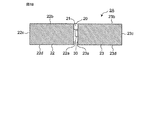
- FIG. 1A is a top view of a positive multi-unit schematically showing an example of the positive multi-unit.
- FIG. 1B is a top view of the negative multi-unit schematically showing an example of the negative multi-unit.
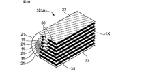
- FIG. 2A is a sketch diagram schematically showing an example of a positive and negative electrode laminate including an electrode multi-unit.
- FIG. 2B is a sketch diagram schematically showing an electrode assembly obtained by bending the positive and negative electrode laminate of FIG. 2A in a non-forming region of the electrode multi-unit.
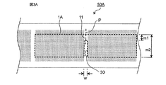
- FIG. 3A is a schematic diagram for explaining a method of cutting out the electrode multi-unit of FIG. 1A from an electrode precursor.
- FIG. 3B is a schematic diagram for explaining a method of cutting out the electrode multi-unit of FIG. 1B from the electrode precursor.
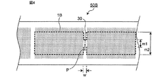
- FIG. 4 is a schematic diagram for explaining a method for cutting out an electrode precursor as an example of an electrode multi-unit.
- FIG. 5 is a schematic diagram for explaining a method for cutting out an electrode precursor from an example of an electrode multi-unit.
- FIG. 6 is a schematic diagram for explaining a method of cutting out an electrode precursor as an example of an electrode multi-unit.
- FIG. 7 is a schematic diagram for explaining a method of cutting out from an electrode precursor, which is an example of an electrode multi-unit.
- FIG. 8 is a schematic diagram for explaining a method for cutting out an electrode precursor as an example of an electrode multi-unit.
- FIG. 9 is a schematic diagram for explaining a method for cutting out an electrode precursor as an example of an electrode multi-unit.
- FIG. 5 is a schematic diagram for explaining a method for cutting out an electrode precursor from an example of an electrode multi-unit.
- FIG. 6 is a schematic diagram for explaining a method of cutting out an electrode precursor as an example of an electrode multi-unit.
- FIG. 7
- FIG. 10 is a schematic diagram for explaining a method of cutting out an electrode precursor as an example of an electrode multi-unit.
- FIG. 11 is a schematic diagram for explaining a method of cutting out an electrode precursor as an example of an electrode multi-unit.
- FIG. 12 is a schematic diagram for explaining a method of cutting out an electrode precursor as an example of an electrode multi-unit.
- FIG. 13 is a schematic diagram for explaining a method of cutting out an electrode precursor as an example of an electrode multi-unit.
- FIG. 14 is a schematic diagram for explaining an electrode precursor.
- the present invention provides a stacked secondary battery (hereinafter sometimes simply referred to as a secondary battery).
- secondary battery refers to a battery that can be repeatedly charged and discharged. Therefore, the secondary battery of the present invention is not excessively bound by its name, and for example, “electric storage device” can be included in the object.
- the direction of “thickness” described directly or indirectly in this specification is based on the stacking direction of the electrodes constituting the secondary battery, that is, “thickness” is a dimension in the stacking direction of the positive electrode and the negative electrode. It corresponds to.
- the secondary battery of the present invention accommodates the electrode assembly and the electrolyte in the exterior body.
- the electrode assembly is formed by alternately laminating positive and negative electrodes via separators. That is, in the electrode assembly, one or more positive electrodes and one or more negative electrodes are alternately stacked via separators, and includes at least one of positive electrodes and negative electrodes.
- the positive electrode and the negative electrode mean a single-layer positive electrode and a single-layer negative electrode in the electrode assembly, respectively.
- An electrode shall be used by the concept containing a positive electrode and a negative electrode.
- the electrode assembly may have a form in which some of the positive electrodes among all the positive electrodes are configured of electrode multi-units, or some of the plurality of negative electrodes.
- the negative electrode may have a form composed of electrode multi-units, or both forms.
- the electrode assembly has a positive and negative electrode laminate including electrode multi-units.
- the electrode multi-unit has an electrode current collector and two or more electrode material layers formed on the electrode current collector through a non-formation region. That is, in the electrode multi-unit, two or more electrode material layers are formed on the electrode current collector with the non-formation region interposed therebetween.
- the electrode material layer portion in such an electrode multi-unit constitutes an electrode of the electrode assembly.
- the electrode material layer portion is a portion including an electrode material layer and an electrode current collector on which the electrode material layer is formed.
- the electrode multi-unit includes a positive electrode multi-unit (that is, a positive electrode multi-unit) and a negative electrode multi-unit (that is, a negative electrode multi-unit).
- the electrode current collector includes a positive electrode current collector and a negative electrode current collector.
- the electrode material layer includes a positive electrode material layer and a negative electrode material layer.
- the positive electrode multi-unit 1A includes, as shown in FIG. 1A, a positive electrode current collector 10 and two or more positive electrode material layers (for example, 12) formed on the positive electrode current collector through a non-formation region 11. 13), and the two or more positive electrode material layer portions constitute two or more positive electrodes.
- the negative electrode multi-unit 2A includes a negative electrode current collector 20 and two or more negative electrode material layers (for example, 22) formed on the negative electrode current collector through a non-formation region 21. , 23), and the two or more negative electrode material layer portions constitute two or more negative electrodes.
- FIG. 1A includes, as shown in FIG. 1A, a positive electrode current collector 10 and two or more positive electrode material layers (for example, 12) formed on the positive electrode current collector through a non-formation region 11. 13), and the two or more positive electrode material layer portions constitute two or more positive electrodes.
- the negative electrode multi-unit 2A includes a negative electrode current collector
- FIG. 1A is a top view of a positive multi-unit schematically showing an example of the positive multi-unit.
- FIG. 1B is a top view of the negative multi-unit schematically showing an example of the negative multi-unit.
- the electrode multi-unit included in the secondary battery (stacked type) of the present invention two or more electrode material layers are formed on the electrode current collector through the non-forming region as described above. For this reason, the secondary battery (stacked type) of the present invention differs from the wound type secondary battery in which the electrode material layer is continuously formed in the winding direction in the form of the electrode material layer. Yes.
- the number of electrode material layers in the electrode multi-unit is the number per side of the electrode current collector.
- the electrode multi-unit usually has two or more electrode material layers formed on both surfaces of the electrode current collector through non-forming regions. In this case, the number, arrangement, and dimensions of the electrode material layers are usually the same on the front and back of the electrode current collector. That is, each electrode material layer on the other surface is formed directly below or directly above a region where each electrode material layer on one surface of the electrode current collector is formed via the electrode current collector. Note that all electrode material layers of one electrode multi-unit have the same polarity.
- the two or more electrode material layers of the electrode multi-unit may each independently have a rectangular shape or an irregular shape in plan view.
- the electrode multi-unit may have a rectangular shape or an irregular shape in plan view.
- the planar view shape of the electrode multi-unit is a planar view shape including all electrode material layers and non-forming regions between them.
- the non-forming region is usually a region positioned between two electrode material layers adjacent to each other through the non-forming region.
- the non-formation region where the electrode multi-unit has the current collecting tab is usually the exposed region of the electrode current collector, the current collecting tab region, and the defective region of the electrode current collector removed for forming the current collecting tab. Include.
- the one electrode multi-unit when one electrode multi-unit has one non-formation region, the one electrode multi-unit has a current collecting tab in the one non-formation region as described later. Further, for example, when one electrode multi-unit has two or more non-formation regions, the one electrode multi-unit has a current collecting tab in one non-formation region of the two non-formation regions as described later Have The number of non-formation regions in the electrode multi-unit is the number of one side of the electrode current collector, and the number of non-formation regions positioned between the two electrode material layers is one. Note that the electrode multi-unit may be normally bent in all non-formation regions.
- the plan view is a state when an object (for example, an electrode multi-unit, an electrode material layer or a secondary battery) is placed and viewed from directly above its thickness (height) direction. Is an agreement.
- the placement is placement in which the surface of the maximum area of an object (for example, an electrode multi-unit, an electrode material layer, or a secondary battery) is the bottom surface.
- the rectangular shape includes so-called rectangles and squares, and is preferably rectangular.
- the irregular shape in the planar shape of the electrode material layer and the electrode multi-unit is a shape having a notch in the planar view. The notch is a part where a part of the cutout is intentionally lost from the initial shape.
- the initial shape before the formation of the notch is usually a quadrangular shape (for example, a rectangular shape).
- the shape in plan view of the notch is not particularly limited, and examples thereof include a quadrangular shape (for example, a rectangular shape), a triangular shape, a sector shape, a semicircular shape, a circular shape, and the like.
- the length m1 (mm) in the folding direction of the non-forming regions 11 and 21 having the current collecting tabs 30 (in particular, the electrodes in the non-forming regions 11 and 21 having the current collecting tabs 30
- the folding direction length m1 (mm) of the exposed area of the current collector (excluding the current collecting tab) is usually 0.7 ⁇ m2 or less when the total length in the folding direction of the electrode multi-unit is m2 (mm). From the viewpoint of ease of forming the current collecting tab and handling of the electrode multi-unit, it is preferably 0.2 ⁇ m 2 or more and 0.5 ⁇ m 2 or less.
- the folding direction is the fold direction (P, Q, R) when it is assumed that the folding in the non-formed region is performed until the crease is formed.
- the positive and negative electrode laminate is a precursor of an electrode assembly that can constitute an electrode assembly by self-folding, and includes one or more electrode multi-units.
- the positive and negative electrode laminates only need to include at least one electrode multi-unit of at least one of a positive electrode multi-unit and a negative electrode multi-unit, and may further include one or more electrode single units.
- An electrode single unit is an electrode single unit having only one electrode material layer per side on the surface of an electrode current collector, a positive electrode single unit (that is, an electrode single unit for a positive electrode) and a negative electrode single unit ( That is, the electrode single unit for negative electrodes) is included.
- an electrode single unit has electrode material layers formed on both sides of an electrode current collector, and does not have a non-formation region (except for a current collecting tab).
- the electrode multi-unit and the electrode single unit are arranged so that the positive electrode and the negative electrode are alternately laminated via the separator in the electrode assembly.
- the positive and negative electrode laminate includes a positive electrode unit (positive electrode multi-unit or single electrode unit) and a negative electrode unit (negative electrode multi-unit or single electrode unit) via a separator. They are stacked alternately.
- the positive and negative electrode laminate includes two or more electrode multi-units
- the two or more electrode multi-units are arranged such that at least non-formed regions overlap each other so that the positive and negative electrode laminates can be bent. Are stacked.
- the non-formed regions overlap each other means that the non-formed regions overlap each other between two or more electrode multi-units in a plan view.
- each non-formation region overlaps in plan view between all two or more electrode multi-units.
- FIG. 2A An example of the positive and negative electrode laminate is shown in FIG. 2A.
- a positive / negative electrode laminate 100A shown in FIG. 2A includes three positive electrode multi-units 1A, four negative electrode multi-units 2A, and one positive electrode single unit 1X.
- the electrode assembly 101A is formed by bending the electrode multi-units 1A and 2A in the non-formation regions 11 and 21.
- the electrode multi-unit 1A Each electrode material layer portion of 2A constitutes each electrode.
- a positive / negative electrode laminate including electrode multi-units is configured once and an electrode assembly is configured using the positive / negative electrode laminate, there is only one electrode material layer per side.
- FIG. 2A is a sketch diagram schematically showing an example of a positive and negative electrode laminate including an electrode multi-unit.
- FIG. 2B is a sketch diagram schematically showing an electrode assembly obtained by bending the positive and negative electrode laminate of FIG. 2A in a non-forming region of the electrode multi-unit. 2A and 2B, the separator between the electrodes is omitted.
- all electrode multi-units have two electrode material layers on both sides of the electrode current collector, and one electrode single unit has electrode material on both sides of the electrode current collector. Has a layer.
- the positive and negative electrode laminate 100A includes a single electrode unit 1X, which is a double-sided electrode multi-unit in which the innermost (lowermost) electrode multi-unit has electrode material layers on both sides of the electrode current collector. Because. In detail, in order to avoid that the electrode material layer of the same polarity in the innermost double-sided electrode multi-unit is continuous in the stacking direction of the electrode assembly, a single electrode unit is included.
- the positive and negative electrode laminates do not necessarily have to include an electrode single unit.
- the innermost (lowermost) electrode multi-unit in the positive and negative electrode laminate is a single-sided electrode multi-unit having an electrode material layer only on one side of the electrode current collector, the single-sided electrode multi-unit is on the other side Since it is folded at (the surface where the electrode material layer is not formed), the positive and negative electrode laminate may not include an electrode single unit from the viewpoint of improving energy density.
- the innermost (lowermost layer) single-sided electrode multi-unit is arranged so as to be folded on the surface where the electrode material layer is not formed at the time of bending. Whether the innermost (lowermost layer) electrode multi-unit is a double-sided electrode or a single-sided electrode depends on the design of the secondary battery.
- the positive and negative electrode laminates preferably contain as many electrode multi-units as possible from the viewpoint of further improving the handleability of the electrodes. That is, as shown in FIG. 2A, the positive and negative electrode laminate preferably includes one or more positive multi-units 1A and one or more negative multi-units 2A. As described above, the innermost (lowermost) electrode When the multi-unit is a double-sided electrode multi-unit, the electrode single unit 1X may be further included. The number of electrode single units 1X is determined according to the number of times of folding of the positive and negative electrode laminates. When the number of times of bending is n (n is a natural number of 1 or more), the number of electrode single units is n.
- the two electrode material layers having the same polarity in the innermost electrode multi-unit are continuous in the stacking direction of the electrode assembly by bending the positive and negative electrode laminate once.
- the single electrode unit 1X is placed one by one at a position substantially sandwiched between the innermost electrode multi-units by each folding. Deploy.
- the substantially sandwiched position means a position sandwiched under the structure of the obtained electrode assembly.
- k is a k-th (k is a natural number of 2 or more) fold, and the k-th fold of the first to “k ⁇ 1” folds is sandwiched by the innermost electrode multi-unit.
- Positions that are not pinched by the second (final) folding are not included.
- the electrode assembly 101A when configured by one-time bending of the positive and negative electrode laminate 100A, the position substantially sandwiched by the innermost electrode multi-unit by the bending.
- One electrode single unit 1X is disposed on the surface. The polarity of the electrode single unit 1X is opposite to the polarity of the innermost electrode multi-unit.
- the positive and negative electrode laminate includes two or more, particularly two or more and eight or less positive multi-units, and two or more, particularly two or more and eight or less negative multi-units, from the viewpoint of further improving the handleability of the electrodes. It is more preferable.
- the two or more electrode multi-units are, for example, the shape and dimensions in plan view and the electrodes so that an electrode assembly having a desired external shape can be obtained.
- the same appearance conditions such as the arrangement, the plan view shape, and the dimensions of two or more electrode material layer formation regions and non-formation regions on the current collector may be used.
- the two or more electrode multi-units may be different in at least one condition selected from the group consisting of the appearance conditions, or both the same and different ones described above may be used. May be.
- the two or more electrode multi-units are laminated so that at least the non-formed regions overlap each other so that the positive and negative electrode laminates can be bent.
- positioning and a dimension of the current collection tab mentioned later are not considered.
- the electrode multi-unit 1A has a rectangular shape in plan view and two electrode material layers in plan view. It has line symmetry.
- the electrode multi-unit 1A is also cut out from the electrode precursor 50A as shown in FIG. 3A.
- the electrode multi-unit 2A has a rectangular shape in plan view and two electrode material layers in a plan view shape, and the two electrode material layers have a plan view shape mutually in a dashed line P. It has line symmetry.
- the electrode multi-unit 2A is also cut out from the electrode precursor 60A as shown in FIG. 3B.
- FIG. 3A is a schematic diagram for explaining a method of cutting out the electrode multi-unit of FIG. 1A from the electrode precursor.
- a broken line is a cutting line
- a one-dot chain line P is a mountain fold or a valley fold at the time of folding. Indicates that it may be.
- FIG. 3B is a schematic diagram for explaining a method of cutting out the electrode multi-unit of FIG.
- a broken line is a cutting line
- a one-dot chain line P is a mountain fold or a valley fold at the time of folding. Indicates that it may be.
- the shape in plan view having line symmetry means that when folded back by a reference line, it completely overlaps, and the shape and dimensions are the same.
- FIGS. 4 to 13 are schematic diagrams for explaining a method of cutting out an electrode precursor from an example of an electrode multi-unit.
- a broken line is a cutting line
- an alternate long and short dash line P is a mountain fold even when folded. It shows that it may be a fold
- the dashed-dotted line Q shows a mountain fold
- the dashed-dotted line R shows a valley fold.
- the electrode multi-unit 1B shown in FIG. 4 has a rectangular shape in plan view and two electrode material layers in a plan view, and the two electrode material layers in a plan view shape with respect to the alternate long and short dash line P. It has symmetry.
- the two or more electrode multi-units 1B include a positive electrode multi-unit 1B and a negative electrode multi-unit 1B in which the arrangement of current collecting tabs is different from each other.
- One of the positive multi-unit 1B or the negative multi-unit 1B may be the same as the electrode multi-unit 1B in FIG. 4, and the other is the same as the electrode multi-unit 1B in FIG. 4 except that the arrangement of the current collecting tabs is different. It's okay.
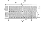
- the electrode multi-unit 1C shown in FIG. 5 has a rectangular shape in plan view and in plan view of the four electrode material layers. Of the four electrode material layers, the two electrode material layers arranged via the alternate long and short dash line have a plan view shape with respect to the alternate long and short dash line.
- the secondary battery has a substantially rectangular parallelepiped appearance.
- the two or more electrode multi-units 1C include a positive electrode multi-unit 1C and a negative electrode multi-unit 1C in which the arrangement of current collecting tabs is different from each other.
- One of the positive multi-unit 1C or the negative multi-unit 1C may be the same as the electrode multi-unit 1C in FIG. 5, and the other is the same as the electrode multi-unit 1C in FIG. 5 except that the arrangement of the current collecting tabs is different. It's okay.
- the electrode multi-unit 1D shown in FIG. 6 has a rectangular shape in plan view and two electrode material layers in plan view, and the two electrode material layers have a line symmetry with respect to the alternate long and short dash line P. No.
- a positive / negative electrode stack obtained by superimposing them is bent once by a one-dot chain line, a secondary battery obtained using the electrode assembly and the electrode assembly Has an external shape with one step portion in a side view.
- the two or more electrode multi-units 1D include a positive electrode multi-unit 1D and a negative electrode multi-unit 1D that are different in the arrangement of current collecting tabs.
- the step portion is a portion composed of two upper surfaces having relatively different heights in side view and a side surface connecting the upper surfaces, and is a discontinuous portion of the upper surface.
- the side view is a state when an object (for example, an electrode assembly or a secondary battery) is placed and viewed from the side in the thickness (height) direction, and is in agreement with the side view.
- the placement is placement in which the surface of the maximum area of an object (for example, an electrode assembly or a secondary battery) is the bottom surface.
- the upper surface is the upper surface when the surface of the maximum area of the object (for example, the electrode assembly or the secondary battery) is the bottom surface.
- the electrode multi-unit 1E shown in FIG. 7 has an irregular shape in plan view, the two electrode material layers in a plan view shape are rectangular, and the two electrode material layers in a plan view shape correspond to the alternate long and short dash line P. Does not have line symmetry.
- a positive / negative electrode laminate obtained by superimposing them is bent once by a one-dot chain line, a secondary battery obtained by using the electrode assembly and the electrode assembly Has an external shape with one step portion in a side view.
- the two or more electrode multi-units 1E include a positive electrode multi-unit 1E and a negative electrode multi-unit 1E in which the arrangement of current collecting tabs is different from each other.
- One of the positive multi-unit 1E or the negative multi-unit 1E may be the same as the electrode multi-unit 1E in FIG. 7, and the other is the same as the electrode multi-unit 1E in FIG. 7 except that the arrangement of the current collecting tabs is different. It's okay.
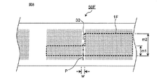
- the electrode multi-unit 1F shown in FIG. 8 has an irregular shape in plan view, the two electrode material layers have a rectangular shape in plan view, and the two electrode material layers have a plan view shape corresponding to the alternate long and short dash line P. Does not have line symmetry.
- a positive / negative electrode laminate obtained by superimposing them is bent once by a one-dot chain line, a secondary battery obtained using the electrode assembly and the electrode assembly Has an external shape with one step portion in a side view.
- the two or more electrode multi-units 1F include a positive electrode multi-unit 1F and a negative electrode multi-unit 1F that are different in the arrangement of current collecting tabs.
- One of the positive multi-unit 1F or the negative multi-unit 1F may be the same as the electrode multi-unit 1F in FIG. 8, and the other is the same as the electrode multi-unit 1F in FIG. 8 except that the arrangement of the current collecting tabs is different. It's okay.
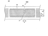
- the electrode multi-unit 1G shown in FIG. 9 has a rectangular shape in plan view and two electrode material layers in plan view, and the two electrode material layers have a line symmetry with respect to the alternate long and short dash line P. No.
- the electrode multi-unit 1G When only two or more electrode multi-units 1G are used as the electrode multi-unit, and the positive and negative electrode laminate obtained by superimposing them is bent once by a one-dot chain line, the electrode assembly and a secondary battery obtained using the electrode assembly are obtained.
- the two or more electrode multi-units 1G include a positive electrode multi-unit 1G and a negative electrode multi-unit 1G in which the arrangement of current collecting tabs is different from each other.
- One of the positive multi-unit 1G or the negative multi-unit 1G may be the same as the electrode multi-unit 1G in FIG. 9, and the other is the same as the electrode multi-unit 1G in FIG. 9 except that the arrangement of the current collecting tabs is different. It's okay.
- the electrode multi-unit 1H shown in FIG. 10 has a rectangular shape in plan view and a plan view shape of the three electrode material layers, and two sets of three electrode material layers are arranged via a one-dot chain line. Neither of the two electrode material layers in plan view has line symmetry with respect to the alternate long and short dash line.
- the secondary battery has an external shape provided with two step portions in a side view.
- the two or more electrode multi-units 1H include a positive electrode multi-unit 1H and a negative electrode multi-unit 1H in which the arrangement of current collecting tabs is different from each other.
- One of the positive multi-unit 1H or the negative multi-unit 1H may be the same as the electrode multi-unit 1H in FIG. 10, and the other is the same as the electrode multi-unit 1H in FIG. 10 except that the arrangement of the current collecting tabs is different. It's okay.
- the electrode multi-unit 1J shown in FIG. 11 has a different shape in plan view, and the shape in plan view of the two electrode material layers is also different, and the shape in plan view of the two electrode material layers is relative to the alternate long and short dash line. Have line symmetry.
- a positive / negative electrode laminate obtained by superimposing them is bent once by a one-dot chain line, a secondary battery obtained using the electrode assembly and the electrode assembly Has an external shape with one notch in plan view.
- the two or more electrode multi-units 1J include a positive electrode multi-unit 1J and a negative electrode multi-unit 1J that are different in the arrangement of current collecting tabs.
- One of the positive multi-unit 1J or the negative multi-unit 1J may be the same as the electrode multi-unit 1J in FIG. 11, and the other is the same as the electrode multi-unit 1J in FIG. 11 except that the arrangement of the current collecting tabs is different. It's okay.
- the electrode multi-unit 1K shown in FIG. 12 has a different shape in plan view, one of the two electrode material layers has a rectangular shape in plan view, and the other has a different shape in plan view.
- the planar view shapes of the two electrode material layers do not have line symmetry with respect to the alternate long and short dash line.
- the two or more electrode multi-units 1K include a positive electrode multi-unit 1K and a negative electrode multi-unit 1K that are different in the arrangement of current collecting tabs.
- One of the positive multi-unit 1K or the negative multi-unit 1K may be the same as the electrode multi-unit 1K in FIG. 12, and the other is the same as the electrode multi-unit 1K in FIG. 12 except that the arrangement of the current collecting tabs is different. It's okay.
- the electrode multi-unit 1L shown in FIG. 13 has a different shape in plan view, one of the two electrode material layers has a rectangular shape in plan view, and the other has a different shape in plan view.
- the planar view shapes of the two electrode material layers do not have line symmetry with respect to the alternate long and short dash line.
- the two or more electrode multi-units 1L include a positive electrode multi-unit 1L and a negative electrode multi-unit 1L in which the arrangement of current collecting tabs is different from each other.
- One of the positive multi-unit 1L or the negative multi-unit 1L may be the same as the electrode multi-unit 1L of FIG. 13, and the other is the same as the electrode multi-unit 1L of FIG. 13 except that the arrangement of the current collecting tabs is different. It's okay.
- All electrode multi-units (positive electrode multi-unit and negative electrode multi-unit) included in the positive and negative electrode laminates are usually formed in a planar view shape and dimensions of the electrode multi-unit and a region where two or more electrode material layers are formed on the electrode current collector.
- the arrangement, the plan view shape, and the size of the non-formation region may be common.
- the dimensions of the electrode material layer formation region in the negative electrode multi-unit and electrode single unit are defined as the electrode material layer formation region in the positive electrode multi-unit and electrode single unit. You may make it slightly larger than the dimension.
- the width w of the non-formed regions 11 and 21 to be bent is particularly limited as long as the electrode assembly can be formed. For example, it may be 3 mm or more and 10 mm or less.
- the width w of the two or more electrode multi-units may be set to be larger as the outer side of the positive and negative electrode multilayer body is bent. In that case, it may be set within the above numerical range.
- the width w of the electrode multi-unit seems to be set larger toward the outside, but it is only exaggerated for the sake of clarity of the drawing.
- the width w is uniform.
- the width w of all the electrode multi-units may be uniform within the above range.
- the electrode multi-unit has a current collecting tab in the non-forming area.
- the electrode multi-unit has a current collecting tab 30 extending from a side adjacent to a non-formed region to be bent among all sides defining two or more electrode material layers in a plan view before bending.
- the side adjacent to the non-formed region may be a side that defines the non-formed region.
- all the sides defining two or more electrode material layers are, for example, the side 22a in the electrode multi-unit 2A of FIG. 1B. 22b, 22c, 22d, 23a, 23b, 23c and 23d.
- adjacent sides Z sides adjacent to the non-formed region 21 to be bent.
- the current collecting tab 30 may be extended from any side of the adjacent sides Z.
- the current collecting tabs 30 are usually extended by one per electrode multi-unit.
- the current collecting tab 30 is made of the same material as that of the electrode current collector.
- the current collecting tab 30 is extended by cutting out using a non-formation region of the electrode material layer. Is done.
- the side where the current collecting tab is extended is the electrode as shown in FIGS. 3A, 3B, and 4 to 13 as long as the side is adjacent to the “non-formed region to be bent”.
- the longitudinal direction of the electrode multi-unit is usually the longitudinal direction r (see FIG. 3) of the electrode current collector as shown in FIGS. 3A, 3B and 4 to 13. 14)).
- the positive and negative electrode laminate includes two or more positive electrode multi-units
- the positive and negative electrode laminate includes two or more negative electrode multi-units
- the positive and negative electrode laminate includes two or more positive electrode multi units and two or more negative electrode multi units
- the two or more positive electrode multi units and the two or more negative electrode multi units are viewed in plan for each polarity. It is preferable to have current collecting tabs at the same location in view of ease of current collection. That is, the two or more positive electrode multi units have current collecting tabs at the same place in plan view, and the two or more negative electrode multi units have current collecting tabs at the same position in plan view. It is preferable that the position of the current collection tab which one or more positive electrode multi-units have differs from the position of the current collection tab which two or more negative electrode multi-units have.
- the position of the current collecting tabs of the two or more positive electrode multi units and the position of the current collecting tabs of the two or more negative electrode multi units are the same side selected from the adjacent sides Z (common) It is more preferable that they are different from each other.
- the current collecting tab 35 of the electrode single unit is an electrode multi-unit 1A having the same polarity as the electrode single unit 1X, as shown in FIGS. 2A and 2B. It is preferable to extend in the same location as the current collection tab 30 which has.
- the number of current collecting tabs can be reduced as compared with the case where current collecting tabs are formed for each electrode. For this reason, the joining property of a current collection tab and the design property of a battery improve.
- the positive and negative electrode laminates are bonded to each other between adjacent electrode multi-units or between electrode single units or between the electrode multi-unit and the electrode single unit from the viewpoint of further improving the handleability of the electrodes. It is preferable. Adhesion can be achieved by using an adhesive separator as a separator, applying an adhesive binder on the electrode material layer, and / or thermocompression bonding.
- every two electrode material layers that are adjacent to each other through the folded non-formed region are formed on the surface of one electrode material layer and the surface of the other electrode material layer. Is normally 0 °, but may be 0 ° or more and 90 ° or less.
- the angle formed by the surface of one electrode material layer and the surface of the other electrode material layer is the smaller of the angles formed by intersecting two surfaces.
- the electrode assembly has folded non-formed regions 11 and 21 on the same side as the current collecting tab 30 as shown in FIG. 2B. For this reason, the energy density of the battery which can make the space by bending and a current collection tab common is improved.
- the outermost positive electrode electrode current collector does not have an electrode material layer on the outside from the viewpoint of preventing deposition of metallic lithium on the negative electrode. . That is, when the outermost electrode is a positive electrode, it is preferable that an electrode material layer that contacts the outer package is not formed on the electrode collector of the outermost positive electrode. More specifically, when the uppermost electrode in the electrode assembly is a positive electrode, the uppermost positive electrode current collector has no electrode material layer on the upper side, and when the lowermost electrode is a positive electrode, The lowermost positive electrode current collector preferably has no electrode material layer on the lower side. The same applies when the uppermost positive electrode and the lowermost positive electrode are provided by either an electrode multi-unit or an electrode single unit.
- the electrodes other than the outermost electrode preferably have electrode material layers on both sides of the electrode current collector from the viewpoint of improving the energy density of the battery.
- electrodes other than the outermost electrode are provided by either an electrode multi-unit or an electrode single unit.
- the innermost (lowermost layer) electrode multi-unit in the positive and negative electrode laminate is a double-sided electrode multi-unit, and the positive and negative electrode laminate includes a single electrode unit, at least two types of Since it is only necessary to prepare electrode units of a size (one type of electrode multi-unit and one type of electrode single unit), it is possible to contribute to cost reduction.
- the innermost (lowermost layer) electrode multi-unit in the positive and negative electrode laminate is a single-sided electrode multi-unit and the positive and negative electrode laminate does not include a single electrode unit
- the electrode multi-unit of at least one kind of size is used. Since it is only necessary to prepare a unit, it is possible to further contribute to cost reduction.
- the positive electrode multi-unit and the negative electrode multi-unit constituting the positive and negative electrode laminate have the same size and the same shape.
- the arrangement of the current collecting tabs between the electrode multi-unit for the positive electrode and the electrode multi-unit for the negative electrode differs depending on the direction of use of the electrode multi-unit of one polarity with respect to the front and back direction.
- the positive electrode multi-unit and the positive electrode single unit are composed of at least a positive electrode material layer and a positive electrode current collector.
- the positive electrode material layer contains a positive electrode active material as an electrode active material.
- the negative electrode multi-unit and the negative electrode single unit are composed of at least a negative electrode material layer and a negative electrode current collector.
- the negative electrode material layer contains a negative electrode active material as an electrode active material.
- Electrode active materials contained in the positive electrode multi-unit, the positive electrode single unit, the negative electrode multi-unit, and the negative electrode single unit, that is, the positive electrode active material and the negative electrode active material are substances directly involved in the transfer of electrons in the secondary battery, It is the main material of the positive and negative electrodes responsible for charge / discharge, that is, battery reaction. More specifically, ions are brought into the electrolyte due to the “positive electrode active material” and the “negative electrode active material”, and these ions move between the positive electrode and the negative electrode to transfer and transfer electrons. Discharge occurs.
- the positive electrode material layer and the negative electrode material layer are particularly preferably layers capable of occluding and releasing lithium ions.
- the secondary battery of the present invention corresponds to a so-called “lithium ion battery”, and the positive electrode material layer and the negative electrode material layer are layers capable of occluding and releasing lithium ions.
- the positive electrode active material of the positive electrode material layer is made of, for example, a granular material, and a binder (also referred to as a “binder”) is included in the positive electrode material layer for sufficient contact between the particles and shape retention. preferable. Furthermore, a conductive additive may be included in the positive electrode material layer in order to facilitate the transmission of electrons that promote the battery reaction.
- the negative electrode active material of the negative electrode material layer is made of, for example, a granular material, and it is preferable that a binder is included for sufficient contact and shape retention between the particles, and smooth transmission of electrons that promote the battery reaction. In order to do so, a conductive aid may be included in the negative electrode material layer.
- the positive electrode material layer and the negative electrode material layer can also be referred to as “positive electrode composite material layer” and “negative electrode composite material layer”, respectively.
- the positive electrode active material is preferably a material that contributes to occlusion and release of lithium ions.
- the positive electrode active material is preferably, for example, a lithium-containing composite oxide.
- the positive electrode active material is preferably a lithium transition metal composite oxide containing lithium and at least one transition metal selected from the group consisting of cobalt, nickel, manganese, and iron. That is, in the positive electrode material layer of the secondary battery of the present invention, such a lithium transition metal composite oxide is preferably included as a positive electrode active material.
- the positive electrode active material may be lithium cobaltate, lithium nickelate, lithium manganate, lithium iron phosphate, or a part of those transition metals replaced with another metal.
- positive electrode active material may be included as a single species, two or more types may be included in combination. Although it is only an illustration to the last, in the secondary battery of this invention, the positive electrode active material contained in a positive electrode material layer may be lithium cobaltate.
- the binder that can be included in the positive electrode material layer is not particularly limited, but includes polyvinylidene fluoride, vinylidene fluoride-hexafluoropropylene copolymer, vinylidene fluoride-tetrafluoroethylene copolymer, and Mention may be made of at least one selected from the group consisting of polytetrafluoroethylene and the like.
- the conductive auxiliary agent that can be included in the positive electrode material layer is not particularly limited, but carbon black such as thermal black, furnace black, channel black, ketjen black, and acetylene black, graphite, carbon nanotube, and vapor phase growth.
- the binder of the positive electrode material layer may be polyvinylidene fluoride
- the conductive additive of the positive electrode material layer may be carbon black.
- the binder and conductive support agent of a positive electrode material layer may be a combination of polyvinylidene fluoride and carbon black.
- the negative electrode active material is preferably a material that contributes to occlusion and release of lithium ions. From this point of view, the negative electrode active material is preferably, for example, various carbon materials, oxides, or lithium alloys.
- Examples of various carbon materials of the negative electrode active material include graphite (natural graphite, artificial graphite), hard carbon, soft carbon, diamond-like carbon, and the like.
- graphite is preferable in that it has high electron conductivity and excellent adhesion to the negative electrode current collector.
- Examples of the oxide of the negative electrode active material include at least one selected from the group consisting of silicon oxide, tin oxide, indium oxide, zinc oxide, lithium oxide, and the like.
- the lithium alloy of the negative electrode active material may be any metal that can be alloyed with lithium.
- Al, Si, Pb, Sn, In, Bi, Ag, Ba, Ca, Hg, Pd, Pt, Te, Zn It may be a binary, ternary or higher alloy of a metal such as La and lithium.
- a binary, ternary or higher alloy of a metal such as La and lithium.
- Such an oxide is preferably amorphous in its structural form. This is because deterioration due to non-uniformity such as crystal grain boundaries or defects is less likely to be caused.
- the negative electrode active material of a negative electrode material layer may be artificial graphite.
- the binder that can be included in the negative electrode material layer is not particularly limited, but is at least one selected from the group consisting of styrene butadiene rubber, polyacrylic acid, polyvinylidene fluoride, polyimide resin, and polyamideimide resin. Can be mentioned.
- the binder contained in the negative electrode material layer may be styrene butadiene rubber.
- the conductive auxiliary agent that can be included in the negative electrode material layer is not particularly limited, but carbon black such as thermal black, furnace black, channel black, ketjen black, and acetylene black, graphite, carbon nanotube, and vapor phase growth.
- Examples thereof include at least one selected from carbon fibers such as carbon fibers, metal powders such as copper, nickel, aluminum and silver, and polyphenylene derivatives.
- the component resulting from the thickener component for example, carboxymethylcellulose used at the time of battery manufacture may be contained in the negative electrode material layer.
- the negative electrode active material and the binder in the negative electrode material layer may be a combination of artificial graphite and styrene butadiene rubber.
- the positive electrode current collector and the negative electrode current collector are members that contribute to collecting and supplying electrons generated in the active material due to the battery reaction.
- a current collector may be a sheet-like metal member and may have a porous or perforated form.
- the current collector may be a metal foil, a punching metal, a net or an expanded metal.
- the positive electrode current collector is preferably made of a metal foil containing at least one selected from the group consisting of aluminum, stainless steel, nickel and the like, and may be, for example, an aluminum foil.
- the negative electrode current collector used for the negative electrode is preferably made of a metal foil containing at least one selected from the group consisting of copper, stainless steel, nickel and the like, and may be, for example, a copper foil.
- the thicknesses of the positive electrode current collector and the negative electrode current collector are not particularly limited as long as the positive and negative electrode laminates can be bent, and may be, for example, 3 ⁇ m or more and 30 ⁇ m or less independently.
- the maximum thickness of the positive electrode multi unit, the positive electrode single unit, the negative electrode multi unit, and the negative electrode single unit is usually 40 ⁇ m or more and 1 mm independently. It may be the following.
- the separator is a member provided from the viewpoint of preventing short circuit due to contact between the positive and negative electrodes and holding the electrolyte.
- the separator can be said to be a member that allows ions to pass while preventing electronic contact between the positive electrode and the negative electrode.
- the separator is a porous or microporous insulating member and has a film form due to its small thickness.
- a polyolefin microporous film may be used as the separator.
- the microporous membrane used as the separator may include, for example, only polyethylene (PE) or only polypropylene (PP) as the polyolefin.
- the separator may be a laminate composed of “a microporous membrane made of PE” and “a microporous membrane made of PP”.
- the surface of the separator may be covered with an inorganic particle coat layer, an adhesive layer, or the like.
- the surface of the separator may have adhesiveness.
- the separator is not particularly limited by its name, and may be a solid electrolyte, a gel electrolyte, insulating inorganic particles or the like having the same function.
- the thickness of such a separator is preferably 5 ⁇ m or more and 30 ⁇ m or less in consideration of prevention of electronic contact between the positive electrode and the negative electrode and bending.
- the electrolyte is preferably a “non-aqueous” electrolyte such as an organic electrolyte or an organic solvent (that is, the electrolyte is a non-aqueous electrolyte). preferable).
- a “non-aqueous” electrolyte such as an organic electrolyte or an organic solvent (that is, the electrolyte is a non-aqueous electrolyte).
- metal ions released from the electrodes positive electrode and negative electrode
- the electrolyte assists the movement of the metal ions in the battery reaction.
- a non-aqueous electrolyte is an electrolyte containing a solvent and a solute.
- a solvent containing at least carbonate is preferable.
- Such carbonates may be cyclic carbonates and / or chain carbonates.
- examples of the cyclic carbonates include at least one selected from the group consisting of propylene carbonate (PC), ethylene carbonate (EC), butylene carbonate (BC), and vinylene carbonate (VC). be able to.
- chain carbonates include at least one selected from the group consisting of dimethyl carbonate (DMC), diethyl carbonate (DEC), ethyl methyl carbonate (EMC), and dipropyl carbonate (DPC).
- DMC dimethyl carbonate
- DEC diethyl carbonate
- EMC ethyl methyl carbonate
- DPC dipropyl carbonate
- the combination of cyclic carbonate and chain carbonate may be used as a non-aqueous electrolyte, for example, the mixture of ethylene carbonate and diethyl carbonate is used.
- a Li salt such as LiPF 6 and / or LiBF 4 is preferably used as LiPF 6 and / or LiBF 4 is preferably used.
- the exterior body may be a flexible pouch (soft bag) or a hard case (hard housing), but is preferably a flexible pouch.
- the flexible pouch is usually formed from a laminate film, and the peripheral portion is heat-sealed to form a seal portion.
- the laminate film a film obtained by laminating a metal foil and a polymer film is generally used.
- a film having a three-layer structure including an outer layer polymer film / metal foil / inner layer polymer film is exemplified.
- the outer layer polymer film is for preventing damage to the metal foil due to permeation and contact of moisture and the like, and polymers such as polyamide and polyester can be suitably used.
- the metal foil is for preventing the permeation of moisture and gas, and a foil of copper, aluminum, stainless steel or the like can be suitably used.
- the inner layer polymer film is for protecting the metal foil from the electrolyte accommodated therein, and for melting and sealing at the time of heat sealing, and polyolefin or acid-modified polyolefin can be suitably used.
- the thickness of the laminate film is not particularly limited, and is preferably 1 ⁇ m or more and 1 mm or less, for example.
- the hard case is usually formed of a metal plate, and the peripheral portion is irradiated with laser to form a seal portion.
- a metal plate a metal material made of aluminum, nickel, iron, copper, stainless steel or the like is common.
- the thickness of a metal plate is not specifically limited, For example, 1 micrometer or more and 1 mm or less are preferable.
- the secondary battery of the present invention can be manufactured by a method including at least an electrode multi-unit manufacturing process, a positive and negative electrode laminate manufacturing process, and an electrode assembly manufacturing process.
- the manufacturing method of the secondary battery of the present invention usually includes an encapsulation step at the end.
- description of an above described multilayer secondary battery can be referred suitably.
- an electrode multi-unit is obtained by cutting out from an electrode precursor in which an electrode material layer is formed on the surface of the electrode current collector.
- the electrode precursor is obtained by applying an electrode material slurry to a metal sheet material (for example, aluminum foil) used as an electrode current collector and rolling it with a roll press.
- a metal sheet material for example, aluminum foil
- an electrode precursor 50 as shown in FIG. 14 is obtained.
- the area to be applied does not correspond to the entire area of the long metal sheet material 51 but corresponds to the width w of the non-formation areas 11 and 21 of the electrode multi-unit described above at least in the longitudinal direction r as shown in FIG. The area is not applied. Furthermore, it is preferable not to apply the metal sheet material 51 to the peripheral region s in both width directions. In consideration of the arrangement of the current collecting tabs, for example, as shown in FIG. 14, a region t where the electrode material slurry is not applied may be provided.
- FIG. 14 is a schematic diagram for explaining an electrode precursor.
- the electrode multi-unit is cut out so that the region where the electrode material slurry is not applied corresponds to the non-formation regions 11 and 21 of the electrode multi-unit. For example, as shown in FIGS. 3A, 3B, and 4 to 13, clipping is performed based on a broken line corresponding to a desired shape. When cutting out, the current collecting tab is provided at a predetermined position.
- the cut-out is merely an example, but may be a so-called “punching operation”.
- a single electrode unit can also be obtained in accordance with the electrode multi-unit manufacturing operation as described above. Specifically, the manufacturing method and manufacturing process of the electrode single unit are the same as the manufacturing method and manufacturing process of the electrode multi-unit except that the cutout shape is different.
- a desired unit selected from the group consisting of an electrode multi-unit and an electrode single unit is laminated and superposed to obtain a positive / negative electrode laminate.
- the positive and negative electrode laminate includes at least one electrode multi-unit.
- the electrode multi-unit and the electrode single unit are arranged so that the positive electrode and the negative electrode are alternately laminated via the separator in the electrode assembly as described above.
- positive and negative electrode laminates are composed of positive electrode units (positive electrode multi-units or electrode single units) and negative electrode units (electrode multi-units or electrode single units) alternately stacked via separators. Is done.
- the positive and negative electrode laminate includes two or more electrode multi-units, as described above, the two or more electrode multi-units are at least a non-formation region so that the positive and negative electrode laminate can be bent. Are stacked so as to overlap each other.
- the electrode multi-unit and the electrode single unit may be individually packaged with a separator.
- the positive and negative electrode laminate includes at least an electrode multi-unit, and does not necessarily include an electrode single unit.
- the positive and negative electrode laminate does not include an electrode single unit, it is only necessary to laminate the electrode multi unit.
- the positive and negative electrode laminate includes an electrode single unit, the electrode multi unit and the electrode single unit May be laminated.
- the bonding can be performed by a method using an adhesive separator as a separator, a method of applying an adhesive binder on the electrode material layer, and / or a method of thermocompression bonding.
- the electrode assembly 101A is obtained by bending the positive and negative electrode laminates at the non-formation regions 11 and 21 of the electrode multi-units 1A and 2A, for example, as shown in FIG. 2B.
- each electrode material layer part of electrode multi-unit 1A, 2A and electrode single unit 1X comprises each electrode.
- the electrode assembly can be obtained simply by bending the positive and negative electrode laminate (that is, the electrode multi-unit constituting the positive and negative electrode laminate and, if desired, the electrode single unit) at a time, the handling of the electrode is improved as a result. . In addition, the production efficiency of the electrode assembly and the secondary battery is improved.
- the number of times of bending may be appropriately determined according to the number of electrode material layers included in one electrode multi-unit.
- Bonding may be performed by bonding electrode material layers that come into contact with each other through a separator for the first time by bending.
- the bonding method a method similar to the bonding method that may be performed in the manufacturing process of the positive and negative electrode laminates can be used.
- a secondary battery can be obtained by enclosing the electrode assembly together with an electrolyte in an outer package.
- the separator may be a laminate of sheets cut into sheets, or may be stacked in a ninety-nine shape and cut off excess.
- the multilayer secondary battery according to the present invention can be used for devices in various fields where power storage is assumed.
- stacked secondary battery which concerns on this invention, especially the nonaqueous electrolyte secondary battery are the electric / information / communication field (for example, a mobile phone, a smart phone, a smart watch, Mobile devices such as notebook computers and digital cameras), home / small industrial applications (eg, power tools, golf carts, home / care / industrial robots), large industrial applications (eg, forklifts, elevators, bays) Port crane field), transportation system field (for example, hybrid vehicle, electric vehicle, bus, train, electric assist bicycle, electric motorcycle, etc.), power system application (for example, various power generation, road conditioner, smart grid, general household) Fields such as stationary power storage systems), and space and deep sea applications (eg It is possible to use the device in the spacecraft, areas such as submersible research vessel), and the like.
- the electric / information / communication field for example, a mobile phone, a smart phone,
- Electrode multi-unit 1X Single electrode unit 10
- 20 Electrode current collector 11
- 21 Electrode Non-formation region of material layer 12
- 22, 23 Electrode material layer 30: Current collecting tab 50, 50A, 50B, 50C, 50D, 50E, 50F, 50G, 50H, 50J, 50K, 50L
- 60A Electrode precursor Body 51: Electrode current collector 100A: Positive and negative electrode laminate 101A: Electrode assembly
Landscapes
- Chemical & Material Sciences (AREA)
- Chemical Kinetics & Catalysis (AREA)
- Electrochemistry (AREA)
- General Chemical & Material Sciences (AREA)
- Engineering & Computer Science (AREA)
- Manufacturing & Machinery (AREA)
- Materials Engineering (AREA)
- Secondary Cells (AREA)
- Connection Of Batteries Or Terminals (AREA)
- Sealing Battery Cases Or Jackets (AREA)
- Battery Electrode And Active Subsutance (AREA)
Abstract
本発明は電極の取り扱い性により一層、優れている積層型二次電池を提供する。本発明は、電極組立体101Aおよび電解質を外装体内に収容した積層型二次電池であって、前記電極組立体101Aにおいて、電極集電体および該電極集電体上に非形成領域11,21を介して形成された2つ以上の電極材層12,13,22,23を有する電極マルチユニット1A,2Aを含む正負極積層体100Aが前記電極マルチユニットの前記非形成領域11,21で折り曲げられており、前記電極マルチユニット1A.2Aは、折り曲げ前の平面視形状において、前記2つ以上の電極材層を規定する全ての辺のうち、前記非形成領域11,21と隣接する辺22a、23aから延設された集電タブを有する、積層型二次電池に関する。
Description
本発明は積層型二次電池およびその製造方法ならびにデバイスに関する。
従来、種々の電子機器の電源として、二次電池が用いられている。二次電池は一般的に外装体内に電極組立体(電極体)および電解質が収容された構造を有している。近年、電子機器の薄型化および小型化が進んでおり、それに伴い、二次電池の薄型化および小型化への要求が高まっている。
二次電池としては、電極組立体が正極と負極を、セパレータを介して交互に積層してなる積層型構造の二次電池がよく知られている。
例えば、特許文献1における積層型の二次電池においては、1つの電極ごとに切り離された正極および負極を用いて積層して電極組立体が製造される。集電タブは、1つの電極ごとに形成されている。
また例えば、特許文献2においては、電極集電体上に電極材層を被覆形成して電極を製造するに際し、2つの電極を非被覆域で連結した対の電極板を製造し、これを用いて電極組立体を製造する技術が開示されている。対の電極板は、電極組立体の組立時に、反対の極性の電極と組み合わせてそのまま使用される。詳しくは、正極と負極とが交互に積層されるように、対の電極板を2つの電極が互いに対向するように非被覆域で折り曲げた後、その間に反対の極性の電極を挿入して、電極組立体が製造される。このような技術においては、集電タブは形成されることなく、折り曲げられた非被覆域が電極端子に接続される。
しかしながら、本発明の発明者等は、上記のような従来の技術では、以下に示すような新たな問題が生じることを見い出した。
(1)特許文献1の技術では、電極は1つずつ切り離されているため、電極の取り扱いが煩雑であり、例えば電極材層の脱落および亀裂の問題が生じた。特許文献2の技術では、対の電極板が使用されるため、電極の取り扱い性の問題はいくらか解消されるものの、対の電極板は電極組立体の組立時にそのまま使用されるため、当該問題はやはり十分に解決されなかった。
(2)特許文献1の技術では、集電タブは1つの電極ごとに形成されるため、短絡時の安全性に問題があった。短絡時の安全性は、電極自体が有する電気抵抗が比較的低いときに問題となる電池性能の1つである。電池の効率的な充電および放電の観点からは、電極の電気抵抗は低いことが好ましいが、電極の電気抵抗が過度に低いと、短絡時に比較的大きな電流が流れるために、発熱による安全性の低下が問題となった。このため、電極には短絡時の安全性の観点から適度な電気抵抗を有することが求められる。短絡時の安全性の問題は、電極の積層枚数が増えると顕著になった。特許文献2の技術では、対の電極板において中央に位置付けられる非被覆域が電極端子に接続されるため、集電タブが1つの電極ごとに形成される場合と比較して、電極の電気抵抗は全体として十分に増大せず、短絡時の安全性はやはり低下した。
(3)特許文献1の技術では、二次電池が上面の高さが異なる段差部を有する場合、サイズの異なる複数の電極を切り出さなければならず、複数のサイズに合わせた複数の切り出し用金型を用意する必要があり、コスト高の原因となった。特許文献2の技術では、対の電極板が有する2つの電極は同じ形状を有するため、二次電池が段差部を有する場合、サイズの異なる複数の電極を切り出さなければならなかった。
(4)特許文献1の技術では、集電タブは1つの電極ごとに形成されるため、電極の積層枚数が増えるにしたがって、集電タブの積層厚さが厚くなった。これによって集電タブの接合性が低下した。また集電タブを収容するための電極端子のサイズが大きくなり、電池セルのデザイン形状を阻害した。
本発明は、電極の取り扱い性により一層、優れ、かつ短絡時の安全性にも優れている積層型二次電池およびその製造方法を提供することを目的とする。
本発明は、
電極組立体および電解質を外装体内に収容した積層型二次電池であって、
前記電極組立体において、電極集電体および該電極集電体上に非形成領域を介して形成された2つ以上の電極材層を有する電極マルチユニットを含む正負極積層体が前記電極マルチユニットの前記非形成領域で折り曲げられており、
前記電極マルチユニットは、折り曲げ前の平面視形状において、前記2つ以上の電極材層を規定する全ての辺のうち、前記非形成領域と隣接する辺から延設された集電タブを有する、積層型二次電池に関する。
電極組立体および電解質を外装体内に収容した積層型二次電池であって、
前記電極組立体において、電極集電体および該電極集電体上に非形成領域を介して形成された2つ以上の電極材層を有する電極マルチユニットを含む正負極積層体が前記電極マルチユニットの前記非形成領域で折り曲げられており、
前記電極マルチユニットは、折り曲げ前の平面視形状において、前記2つ以上の電極材層を規定する全ての辺のうち、前記非形成領域と隣接する辺から延設された集電タブを有する、積層型二次電池に関する。
本発明はまた、
上記積層型二次電池の製造方法であって、
電極集電体表面に電極材層を形成した電極前駆体から切り出し、電極マルチユニットを得る工程、
前記電極マルチユニットを積層し、重ね合わせて、正負極積層体を得る工程、および
前記正負極積層体を前記電極マルチユニットの非形成領域で折り曲げて電極組立体を得る工程、
を含む、積層型二次電池の製造方法に関する。
上記積層型二次電池の製造方法であって、
電極集電体表面に電極材層を形成した電極前駆体から切り出し、電極マルチユニットを得る工程、
前記電極マルチユニットを積層し、重ね合わせて、正負極積層体を得る工程、および
前記正負極積層体を前記電極マルチユニットの非形成領域で折り曲げて電極組立体を得る工程、
を含む、積層型二次電池の製造方法に関する。
本発明の積層型二次電池は、電極の取り扱い性により一層、優れているため、電極材層の脱落および亀裂が抑制されている。
本発明の積層型二次電池はまた、短絡時の安全性にも優れている。
本発明の積層型二次電池はまた、1つの電極ごとに集電タブが形成される場合と比較して、集電タブの数を低減することができるため、集電タブの接合性および電池のデザイン性が向上する。
本発明の積層型二次電池はまた、短絡時の安全性にも優れている。
本発明の積層型二次電池はまた、1つの電極ごとに集電タブが形成される場合と比較して、集電タブの数を低減することができるため、集電タブの接合性および電池のデザイン性が向上する。
[積層型二次電池]
本発明は積層型二次電池(以下、単に二次電池ということがある)を提供する。本明細書でいう「二次電池」とは、充電および放電の繰り返しが可能な電池のことを指している。従って、本発明の二次電池は、その名称に過度に拘泥されるものでなく、例えば“蓄電デバイス”なども対象に含まれ得る。
本発明は積層型二次電池(以下、単に二次電池ということがある)を提供する。本明細書でいう「二次電池」とは、充電および放電の繰り返しが可能な電池のことを指している。従って、本発明の二次電池は、その名称に過度に拘泥されるものでなく、例えば“蓄電デバイス”なども対象に含まれ得る。
(二次電池の構造)
以下、本発明の二次電池について、幾つかの実施態様を示す図面を用いて詳しく説明するが、図面における各種の要素は、本発明の理解のために模式的かつ例示的に示したにすぎず、外観および寸法比などは実物と異なり得る。本明細書で直接的または間接的に用いる“上下方向”、“左右方向”および“表裏方向”はそれぞれ、図中における上下方向、左右方向および表裏方向に対応した方向に相当する。特記しない限り、同じ符号または記号は、同じ部材または同じ意味内容を示すものとする。本明細書で直接的または間接的に説明される“厚み”の方向は、二次電池を構成する電極の積層方向に基づいており、即ち、“厚み”は正極と負極との積層方向における寸法に相当する。
以下、本発明の二次電池について、幾つかの実施態様を示す図面を用いて詳しく説明するが、図面における各種の要素は、本発明の理解のために模式的かつ例示的に示したにすぎず、外観および寸法比などは実物と異なり得る。本明細書で直接的または間接的に用いる“上下方向”、“左右方向”および“表裏方向”はそれぞれ、図中における上下方向、左右方向および表裏方向に対応した方向に相当する。特記しない限り、同じ符号または記号は、同じ部材または同じ意味内容を示すものとする。本明細書で直接的または間接的に説明される“厚み”の方向は、二次電池を構成する電極の積層方向に基づいており、即ち、“厚み”は正極と負極との積層方向における寸法に相当する。
本発明の二次電池は電極組立体および電解質を外装体内に収容する。
電極組立体は正極と負極がセパレータを介して交互に積層されてなる。すなわち、電極組立体は、1つ以上の正極と1つ以上の負極がセパレータを介して交互に積層されており、正極または負極の少なくとも一方を2つ以上含む。本明細書で正極および負極はそれぞれ、特記しない限り、電極組立体における1層の正極および1層の負極を意味するものとする。電極は正極および負極を包含する概念で用いるものとする。
本発明において電極組立体を構成する全ての正極および全ての負極のうち、少なくとも一方の極性の電極、好ましくは両方の極性の電極において、少なくとも一部の複数の電極は後述の電極マルチユニットから構成されている。詳しくは、電極組立体は、全ての正極のうちの一部の複数の正極が電極マルチユニットから構成されている形態を有していてもよいし、全ての負極のうちの一部の複数の負極が電極マルチユニットから構成されている形態を有していてもよいし、またはこれらの両方の形態を有していてもよい。
本発明において電極組立体は電極マルチユニットを含む正負極積層体を有する。
電極マルチユニットは、電極集電体および該電極集電体上に非形成領域を介して形成された2つ以上の電極材層を有する。すなわち、電極マルチユニットにおいて、2つ以上の電極材層は電極集電体上、相互に非形成領域を挟んで形成されている。このような電極マルチユニットにおける電極材層部分が電極組立体の電極を構成するようになる。電極材層部分とは電極材層と当該電極材層が形成されている電極集電体を含む部分のことである。電極マルチユニットは正極マルチユニット(すなわち、正極用の電極マルチユニット)および負極マルチユニット(すなわち、負極用の電極マルチユニット)を包含する。電極集電体は正極集電体および負極集電体を包含する。電極材層は正極材層および負極材層を包含する。詳しくは、正極マルチユニット1Aは、図1Aに示すように、正極集電体10および該正極集電体上に非形成領域11を介して形成された2つ以上の正極材層(例えば、12,13)を有し、当該2つ以上の正極材層部分で2つ以上の正極を構成する。また例えば、負極マルチユニット2Aは、図1Bに示すように、負極集電体20および該負極集電体上に非形成領域21を介して形成された2つ以上の負極材層(例えば、22,23)を有し、当該2つ以上の負極材層部分で2つ以上の負極を構成する。図1Aは正極マルチユニットの一例を模式的に示す正極マルチユニットの上面図である。図1Bは負極マルチユニットの一例を模式的に示す負極マルチユニットの上面図である。本発明の二次電池(積層型)に含まれる電極マルチユニットにおいては、2つ以上の電極材層は上記のように電極集電体上、非形成領域を介して形成される。このため、本発明の二次電池(積層型)は、電極材層が巻回方向に連続的に形成されている巻回型二次電池とは、電極材層の形成形態の点で異なっている。
電極マルチユニットにおける電極材層の数は電極集電体の片面あたりの数である。電極マルチユニットは通常、電極集電体の両面それぞれに、非形成領域を介して形成された2つ以上の電極材層を有する。この場合、電極集電体の表と裏において電極材層の数、配置および寸法は通常、一致する。すなわち、電極集電体の一方の面の各電極材層が形成されている領域の直下または直上に電極集電体を介して他方の面の各電極材層が形成されている。なお、1つの電極マルチユニットが有する全ての電極材層は同じ極性を有する。
電極マルチユニットが有する2つ以上の電極材層はそれぞれ独立して、平面視において、矩形状または異形状を有していてよい。
電極マルチユニットは、平面視において、矩形状または異形状を有していてよい。電極マルチユニットの平面視形状は、全ての電極材層およびそれらの間の非形成領域を含む平面視形状である。非形成領域は通常、当該非形成領域を介して相互に隣接する2つの電極材層間に位置付けられる領域のことである。後述するように電極マルチユニットが集電タブを有する非形成領域は通常、電極集電体の露出領域、集電タブ領域および集電タブ形成のために除去された電極集電体の欠損領域を包含する。例えば、1つの電極マルチユニットが1つの非形成領域を有する場合、当該1つの電極マルチユニットが当該1つの非形成領域に後述のように集電タブを有する。また例えば、1つの電極マルチユニットが2つ以上の非形成領域を有する場合、当該1つの電極マルチユニットが当該2つの非形成領域のうちいずれか1つの非形成領域に後述のように集電タブを有する。電極マルチユニットにおける非形成領域の数は電極集電体の片面あたりの数であり、2つの電極材層間に位置付けられる非形成領域の数は1つである。なお電極マルチユニットは通常、全ての非形成領域で折り曲げられてもよい。
平面視とは、対象物(例えば、電極マルチユニット、電極材層または二次電池)を載置してその厚み(高さ)方向の真上から見たときの状態のことであり、平面図と同意である。載置は対象物(例えば、電極マルチユニット、電極材層または二次電池)の最大面積の面を底面にした載置である。矩形状はいわゆる長方形および正方形を包含し、好ましくは長方形である。電極材層および電極マルチユニットの平面視形状における異形状とは、平面視において切り欠き部を有する形状のことである。切り欠き部とは、初期の形状からその一部を意図的に欠損させた部分のことである。切り欠き部形成前の初期の形状は通常、四角形状(例えば、矩形状)である。切り欠き部の平面視形状は特に限定されず、例えば、四角形状(例えば、矩形状)、三角形状、扇形形状、半円形状、円形状等が挙げられる。
電極マルチユニットは、平面視において、矩形状または異形状を有していてよい。電極マルチユニットの平面視形状は、全ての電極材層およびそれらの間の非形成領域を含む平面視形状である。非形成領域は通常、当該非形成領域を介して相互に隣接する2つの電極材層間に位置付けられる領域のことである。後述するように電極マルチユニットが集電タブを有する非形成領域は通常、電極集電体の露出領域、集電タブ領域および集電タブ形成のために除去された電極集電体の欠損領域を包含する。例えば、1つの電極マルチユニットが1つの非形成領域を有する場合、当該1つの電極マルチユニットが当該1つの非形成領域に後述のように集電タブを有する。また例えば、1つの電極マルチユニットが2つ以上の非形成領域を有する場合、当該1つの電極マルチユニットが当該2つの非形成領域のうちいずれか1つの非形成領域に後述のように集電タブを有する。電極マルチユニットにおける非形成領域の数は電極集電体の片面あたりの数であり、2つの電極材層間に位置付けられる非形成領域の数は1つである。なお電極マルチユニットは通常、全ての非形成領域で折り曲げられてもよい。
平面視とは、対象物(例えば、電極マルチユニット、電極材層または二次電池)を載置してその厚み(高さ)方向の真上から見たときの状態のことであり、平面図と同意である。載置は対象物(例えば、電極マルチユニット、電極材層または二次電池)の最大面積の面を底面にした載置である。矩形状はいわゆる長方形および正方形を包含し、好ましくは長方形である。電極材層および電極マルチユニットの平面視形状における異形状とは、平面視において切り欠き部を有する形状のことである。切り欠き部とは、初期の形状からその一部を意図的に欠損させた部分のことである。切り欠き部形成前の初期の形状は通常、四角形状(例えば、矩形状)である。切り欠き部の平面視形状は特に限定されず、例えば、四角形状(例えば、矩形状)、三角形状、扇形形状、半円形状、円形状等が挙げられる。
電極マルチユニット(例えば、1A,2A)において、集電タブ30を有する非形成領域11,21の折り曲げ方向長さm1(mm)(特に、集電タブ30を有する非形成領域11,21における電極集電体の露出領域(集電タブを除く)の折り曲げ方向長さm1(mm))は、電極マルチユニットの折り曲げ方向の全長をm2(mm)としたとき、通常、0.7×m2以下であってよく、集電タブの形成容易性および電極マルチユニットの取扱い性の観点から、好ましくは0.2×m2以上、0.5×m2以下である。折り曲げ方向とは、当該非形成領域での折り曲げを折り目がつくまで行うと仮定したときの、折り目方向(P,Q,R)のことである。
正負極積層体は、自己の折り曲げにより電極組立体を構成することができる電極組立体の前駆体であり、1つ以上の電極マルチユニットを含む。すなわち、正負極積層体は、正極マルチユニットまたは負極マルチユニットの少なくとも一方の電極マルチユニットを1つ以上含んでいればよく、また1つ以上の電極単一ユニットをさらに含んでもよい。
電極単一ユニットは電極集電体の表面に電極材層を片面あたり1つのみ有する電極単一ユニットであり、正極単一ユニット(すなわち、正極用の電極単一ユニット)および負極単一ユニット(すなわち、負極用の電極単一ユニット)を包含する。電極単一ユニットは通常、電極集電体の両面に電極材層が形成されており、非形成領域(集電タブは除く)は有さない。
正負極積層体において電極マルチユニットおよび電極単一ユニットは、電極組立体において正極と負極とがセパレータを介して交互に積層されるように配置されている。例えば、正負極積層体は、正極用のユニット(正極用の電極マルチユニットまたは電極単一ユニット)と、負極用のユニット(負極用の電極マルチユニットまたは電極単一ユニット)とがセパレータを介して交互に積層されている。また例えば、正負極積層体が2つ以上の電極マルチユニットを含む場合、当該2つ以上の電極マルチユニットは、正負極積層体の折り曲げが可能なように、少なくとも非形成領域が相互に重なり合うように積層されている。非形成領域が相互に重なり合うとは、平面視で、2つ以上の電極マルチユニット間において各非形成領域が重なり合っている、という意味である。好ましくは2つ以上の全ての電極マルチユニット間において各非形成領域は平面視で重なり合っている。
正負極積層体の一例を図2Aに示す。図2Aに示す正負極積層体100Aは、3つの正極マルチユニット1A、4つの負極マルチユニット2Aおよび1つの正極単一ユニット1Xを含む。このような正負極積層体100Aを、図2Bに示すように、電極マルチユニット1A、2Aの非形成領域11,21で折り曲げることにより、電極組立体101Aは構成され、結果として電極マルチユニット1A、2Aの各電極材層部分が各電極を構成する。本発明においては、このように電極マルチユニットを含む正負極積層体を一旦、構成し、この正負極積層体を用いて電極組立体を構成するため、電極材層を片面あたり1つのみしか有さない電極単一ユニットのみを用いる場合と比較して、電極の取り扱い性が向上する。このため、電極の取り扱い時における電極材層の脱落および亀裂が防止される。図2Aは、電極マルチユニットを含む正負極積層体の一例を模式的に示す見取り図である。図2Bは、図2Aの正負極積層体を電極マルチユニットの非形成領域で折り曲げて得られる電極組立体を模式的に示す見取り図である。なお、図2Aおよび図2Bでは電極間のセパレータが省略されている。図2Aの正負極積層体において、全ての電極マルチユニットは電極集電体の両面それぞれに2つの電極材層を有しており、1つの電極単一ユニットは電極集電体の両面に電極材層を有している。
図2Aにおいて正負極積層体100Aは電極単一ユニット1Xを含むが、これは、最内側(最下層)の電極マルチユニットが電極集電体の両面に電極材層を有する両面電極マルチユニットであるためである。詳しくは、最内側の両面電極マルチユニットにおける同極性の電極材層が電極組立体の積層方向で連続するのを回避するために、電極単一ユニットが含まれる。正負極積層体は必ずしも電極単一ユニットを含まなければならないというわけではない。例えば、正負極積層体における最内側(最下層)の電極マルチユニットが電極集電体の一方の面のみに電極材層を有する片面電極マルチユニットである場合、当該片面電極マルチユニットは他方の面(電極材層が形成されていない面)で折り合わされるため、エネルギー密度向上の観点から、当該正負極積層体は電極単一ユニットを含まなくてもよい。この場合、最内側(最下層)の片面電極マルチユニットは、折り曲げ時に、電極材層が形成されていない面で折り合わされるように配置される。なお、最内側(最下層)の電極マルチユニットを両面電極にするか片面電極にするかは二次電池の設計に依存する事項である。
正負極積層体は、電極の取り扱い性のさらなる向上の観点から、できるだけ多くの電極マルチユニットを含むことが好ましい。すなわち、正負極積層体は、図2Aに示すように、1つ以上の正極マルチユニット1Aおよび1つ以上の負極マルチユニット2Aを含むことが好ましく、上記したように最内側(最下層)の電極マルチユニットが両面電極マルチユニットである場合には電極単一ユニット1Xをさらに含んでもよい。電極単一ユニット1Xの数は正負極積層体の折り曲げ回数に応じて決定され、折り曲げ回数がn(nは1以上の自然数)のとき、電極単一ユニットの数はnである。正負極積層体の1回の折り曲げにより、最内側の1つの電極マルチユニットにおける同極性の2つの電極材層が電極組立体の積層方向で連続するためである。詳しくは、正負極積層体のn回の折り曲げにより電極組立体を構成する場合には、各回の折り曲げで最内側の電極マルチユニットにより実質的に挟まれる位置に電極単一ユニット1Xを1つずつ配置する。実質的に挟まれる位置とは、得られる電極組立体の構造の下で挟まれる位置を意味する。実質的に挟まれる位置には、例えば、k回(kは2以上の自然数)の折り曲げのうち、1回目から「k-1」回目の折り曲げで最内側の電極マルチユニットにより挟まれるものの、k回目(最終回)の折り曲げで挟まれなくなる位置は含まれない。例えば、図2Aおよび図2Bに示すように、正負極積層体100Aの1回の折り曲げで電極組立体101Aを構成する場合には、当該折り曲げで最内側の電極マルチユニットにより実質的に挟まれる位置に電極単一ユニット1Xを1つ配置する。なお、電極単一ユニット1Xの極性は、最内側の電極マルチユニットの極性と反対の極性である。
正負極積層体は、電極の取り扱い性のさらなる向上の観点から、2つ以上、特に2つ以上8つ以下の正極マルチユニットおよび2つ以上、特に2つ以上8つ以下の負極マルチユニットを含むことがより好ましい。
正負極積層体が2つ以上の電極マルチユニットを含む場合、当該2つ以上の電極マルチユニットは、所望の外観形状の電極組立体が得られるように、例えば、その平面視形状および寸法ならびに電極集電体上における2つ以上の電極材層の形成領域および非形成領域の配置、平面視形状および寸法等の外観条件が同じものを用いてもよい。また例えば、当該2つ以上の電極マルチユニットは、当該外観条件からなる群から選択される少なくとも1つの条件が異なるものを用いてもよいし、または上記した同じものと異なるものとの両方を用いてもよい。いずれの場合においも、上記したように、当該2つ以上の電極マルチユニットは、正負極積層体の折り曲げが可能なように、少なくとも非形成領域が相互に重なり合うように積層される。なお、電極マルチユニットの平面視形状について、後述する集電タブの配置および寸法は考慮しない。
例えば、図2Aの正負極積層体100Aにおいては、全ての電極マルチユニット1Aおよび2Aとして上記全ての外観条件が同じものが使用されている。電極マルチユニット1Aは、図3Aに示すように、その平面視形状および2つの電極材層の平面視形状が矩形状であって、2つの電極材層の平面視形状は相互に一点鎖線Pに対して線対称性を有する。電極マルチユニット1Aはまた図3Aに示すように電極前駆体50Aから切り出されたものである。電極マルチユニット2Aは、図3Bに示すように、その平面視形状および2つの電極材層の平面視形状が矩形状であって、2つの電極材層の平面視形状は相互に一点鎖線Pに対して線対称性を有する。電極マルチユニット2Aはまた図3Bに示すように電極前駆体60Aから切り出されたものである。電極マルチユニットとして1つ以上の電極マルチユニット1Aおよび1つ以上の電極マルチユニット2Aのみを用い、これらを重ね合わせた正負極積層体を一点鎖線で1回折り曲げると、電極組立体(図2B参照)および当該電極組立体を用いて得られる二次電池は略直方体の外観形状を有する。図3Aは、図1Aの電極マルチユニットの、電極前駆体からの切り出し方法を説明するための模式図であり、破線は切り出し線、一点鎖線Pは折り曲げに際して山折りであっても谷折りであってもよいことを示す。図3Bは、図1Bの電極マルチユニットの、電極前駆体からの切り出し方法を説明するための模式図であり、破線は切り出し線、一点鎖線Pは折り曲げに際して山折りであっても谷折りであってもよいことを示す。平面視形状が線対称性を有するとは、基準となる線で折り返したとき、完全に重なり合うことを意味し、当該形状も寸法も同じであることをいう。
電極マルチユニットの具体例を図4~図13に示す。図4~図13はそれぞれ、電極マルチユニットの一例の、電極前駆体からの切り出し方法を説明するための模式図であり、破線は切り出し線、一点鎖線Pは折り曲げに際して山折りであっても谷折りであってもよいことを示し、一点鎖線Qは山折りを示し、一点鎖線Rは谷折りを示す。
図4に示す電極マルチユニット1Bは、その平面視形状および2つの電極材層の平面視形状が矩形状であって、2つの電極材層の平面視形状が相互に一点鎖線Pに対して線対称性を有する。電極マルチユニットとして2つ以上の電極マルチユニット1Bのみを用い、これらを重ね合わせた正負極積層体を一点鎖線で1回折り曲げると、電極組立体および当該電極組立体を用いて得られる二次電池は略直方体の外観形状を有する。なお、2つ以上の電極マルチユニット1Bには、集電タブの配置が相互に異なる正極マルチユニット1Bおよび負極マルチユニット1Bが含まれる。正極マルチユニット1Bまたは負極マルチユニット1Bの一方は図4の電極マルチユニット1Bと同様であってよく、他方は、集電タブの配置が異なること以外、図4の電極マルチユニット1Bと同様であってよい。
図5に示す電極マルチユニット1Cは、その平面視形状および4つの電極材層の平面視形状が矩形状である。4つの電極材層のうち、一点鎖線を介して配置される2つの電極材層の平面視形状は相互に一点鎖線に対して線対称性を有する。電極マルチユニットとして2つ以上の電極マルチユニット1Cのみを用い、これらを重ね合わせた正負極積層体をそれぞれの一点鎖線で1回ずつ折り曲げると、電極組立体および当該電極組立体を用いて得られる二次電池は略直方体の外観形状を有する。なお、2つ以上の電極マルチユニット1Cには、集電タブの配置が相互に異なる正極マルチユニット1Cおよび負極マルチユニット1Cが含まれる。正極マルチユニット1Cまたは負極マルチユニット1Cの一方は図5の電極マルチユニット1Cと同様であってよく、他方は、集電タブの配置が異なること以外、図5の電極マルチユニット1Cと同様であってよい。
図6に示す電極マルチユニット1Dは、その平面視形状および2つの電極材層の平面視形状が矩形状であって、2つの電極材層の平面視形状は一点鎖線Pに対する線対称性を有さない。電極マルチユニットとして2つ以上の電極マルチユニット1Dのみを用い、これらを重ね合わせた正負極積層体を一点鎖線で1回折り曲げると、電極組立体および当該電極組立体を用いて得られる二次電池は側面視において1つの段差部を備えた外観形状を有する。なお、2つ以上の電極マルチユニット1Dには、集電タブの配置が相互に異なる正極マルチユニット1Dおよび負極マルチユニット1Dが含まれる。正極マルチユニット1Dまたは負極マルチユニット1Dの一方は図6の電極マルチユニット1Dと同様であってよく、他方は、集電タブの配置が異なること以外、図6の電極マルチユニット1Dと同様であってよい。段差部とは、側面視において高さが相対的に異なる2つの上面とそれらの上面を連結する側面から構成される部分のことであり、上面の不連続部分のことである。側面視とは、対象物(例えば、電極組立体または二次電池)を載置してその厚み(高さ)方向の真横から見たときの状態のことであり、側面図と同意である。載置は対象物(例えば、電極組立体または二次電池)の最大面積の面を底面にした載置である。上面は、対象物(例えば、電極組立体または二次電池)の最大面積の面を底面にしたときの上面のことである。
図7に示す電極マルチユニット1Eは、その平面視形状が異形状であり、2つの電極材層の平面視形状が矩形状であって、2つの電極材層の平面視形状は一点鎖線Pに対する線対称性を有さない。電極マルチユニットとして2つ以上の電極マルチユニット1Eのみを用い、これらを重ね合わせた正負極積層体を一点鎖線で1回折り曲げると、電極組立体および当該電極組立体を用いて得られる二次電池は側面視において1つの段差部を備えた外観形状を有する。なお、2つ以上の電極マルチユニット1Eには、集電タブの配置が相互に異なる正極マルチユニット1Eおよび負極マルチユニット1Eが含まれる。正極マルチユニット1Eまたは負極マルチユニット1Eの一方は図7の電極マルチユニット1Eと同様であってよく、他方は、集電タブの配置が異なること以外、図7の電極マルチユニット1Eと同様であってよい。
図8に示す電極マルチユニット1Fは、その平面視形状が異形状であり、2つの電極材層の平面視形状が矩形状であって、2つの電極材層の平面視形状は一点鎖線Pに対する線対称性を有さない。電極マルチユニットとして2つ以上の電極マルチユニット1Fのみを用い、これらを重ね合わせた正負極積層体を一点鎖線で1回折り曲げると、電極組立体および当該電極組立体を用いて得られる二次電池は側面視において1つの段差部を備えた外観形状を有する。なお、2つ以上の電極マルチユニット1Fには、集電タブの配置が相互に異なる正極マルチユニット1Fおよび負極マルチユニット1Fが含まれる。正極マルチユニット1Fまたは負極マルチユニット1Fの一方は図8の電極マルチユニット1Fと同様であってよく、他方は、集電タブの配置が異なること以外、図8の電極マルチユニット1Fと同様であってよい。
図9に示す電極マルチユニット1Gは、その平面視形状および2つの電極材層の平面視形状が矩形状であって、2つの電極材層の平面視形状は一点鎖線Pに対する線対称性を有さない。電極マルチユニットとして2つ以上の電極マルチユニット1Gのみを用い、これらを重ね合わせた正負極積層体を一点鎖線で1回折り曲げると、電極組立体および当該電極組立体を用いて得られる二次電池は側面視において1つの段差部を備えた外観形状を有する。なお、2つ以上の電極マルチユニット1Gには、集電タブの配置が相互に異なる正極マルチユニット1Gおよび負極マルチユニット1Gが含まれる。正極マルチユニット1Gまたは負極マルチユニット1Gの一方は図9の電極マルチユニット1Gと同様であってよく、他方は、集電タブの配置が異なること以外、図9の電極マルチユニット1Gと同様であってよい。
図10に示す電極マルチユニット1Hは、その平面視形状および3つの電極材層の平面視形状が矩形状であって、3つの電極材層のうち、一点鎖線を介して配置される2組の2つの電極材層の平面視形状はいずれも、それぞれの一点鎖線に対する線対称性を有さない。電極マルチユニットとして2つ以上の電極マルチユニット1Hのみを用い、これらを重ね合わせた正負極積層体をそれぞれの一点鎖線で1回ずつ折り曲げると、電極組立体および当該電極組立体を用いて得られる二次電池は側面視において2つの段差部を備えた外観形状を有する。なお、2つ以上の電極マルチユニット1Hには、集電タブの配置が相互に異なる正極マルチユニット1Hおよび負極マルチユニット1Hが含まれる。正極マルチユニット1Hまたは負極マルチユニット1Hの一方は図10の電極マルチユニット1Hと同様であってよく、他方は、集電タブの配置が異なること以外、図10の電極マルチユニット1Hと同様であってよい。
図11に示す電極マルチユニット1Jは、その平面視形状が異形状であり、2つの電極材層の平面視形状も異形状であって、2つの電極材層の平面視形状は一点鎖線に対して線対称性を有する。電極マルチユニットとして2つ以上の電極マルチユニット1Jのみを用い、これらを重ね合わせた正負極積層体を一点鎖線で1回折り曲げると、電極組立体および当該電極組立体を用いて得られる二次電池は平面視において1つの切り欠き部を備えた外観形状を有する。なお、2つ以上の電極マルチユニット1Jには、集電タブの配置が相互に異なる正極マルチユニット1Jおよび負極マルチユニット1Jが含まれる。正極マルチユニット1Jまたは負極マルチユニット1Jの一方は図11の電極マルチユニット1Jと同様であってよく、他方は、集電タブの配置が異なること以外、図11の電極マルチユニット1Jと同様であってよい。
図12に示す電極マルチユニット1Kは、その平面視形状が異形状であり、2つの電極材層のうち一方の平面視形状は矩形状であり、他方の平面視形状は異形状である。2つの電極材層の平面視形状は一点鎖線に対して線対称性を有さない。電極マルチユニットとして2つ以上の電極マルチユニット1Kのみを用い、これらを重ね合わせた正負極積層体を一点鎖線で1回折り曲げると、電極組立体および当該電極組立体を用いて得られる二次電池は、側面視において1つの段差部を備えた外観形状を有する。なお、2つ以上の電極マルチユニット1Kには、集電タブの配置が相互に異なる正極マルチユニット1Kおよび負極マルチユニット1Kが含まれる。正極マルチユニット1Kまたは負極マルチユニット1Kの一方は図12の電極マルチユニット1Kと同様であってよく、他方は、集電タブの配置が異なること以外、図12の電極マルチユニット1Kと同様であってよい。
図13に示す電極マルチユニット1Lは、その平面視形状が異形状であり、2つの電極材層のうち一方の平面視形状は矩形状であり、他方の平面視形状は異形状である。2つの電極材層の平面視形状は一点鎖線に対して線対称性を有さない。電極マルチユニットとして2つ以上の電極マルチユニット1Lのみを用い、これらを重ね合わせた正負極積層体を一点鎖線で1回折り曲げると、電極組立体および当該電極組立体を用いて得られる二次電池は、側面視において1つの段差部を備えた外観形状を有する。なお、2つ以上の電極マルチユニット1Lには、集電タブの配置が相互に異なる正極マルチユニット1Lおよび負極マルチユニット1Lが含まれる。正極マルチユニット1Lまたは負極マルチユニット1Lの一方は図13の電極マルチユニット1Lと同様であってよく、他方は、集電タブの配置が異なること以外、図13の電極マルチユニット1Lと同様であってよい。
正負極積層体に含まれる全ての電極マルチユニット(正極マルチユニットおよび負極マルチユニット)は通常、電極マルチユニットの平面視形状および寸法ならびに電極集電体上における2つ以上の電極材層の形成領域および前記非形成領域の配置、平面視形状および寸法が共通していてもよい。負極への金属リチウムの析出防止の観点から、負極の電極マルチユニットおよび電極単一ユニットにおける電極材層の形成領域の寸法を、正極の電極マルチユニットおよび電極単一ユニットにおける電極材層の形成領域の寸法よりも僅かに大きくしてもよい。
電極マルチユニットにおいて、折り曲げられる非形成領域11,21の幅w(すなわち、非形成領域11,21を介して隣接する2つの電極材層間の距離)は、電極組立体が構成され得る限り特に限定されず、例えば、3mm以上10mm以下であってよい。正負極積層体が2つ以上の電極マルチユニットを含む場合、当該2つ以上の電極マルチユニットにおける幅wは、正負極積層体の折り曲げに際し、配置が外側ほど大きく設定してもよい。その場合には上記の数値範囲内で設定されればよい。図2Bにおいては、電極マルチユニットの幅wは配置が外側ほど大きく設定されているように見えるが、図面の明瞭化のために誇張されているにすぎず、実際には、全ての電極マルチユニットの幅wは均一である。正負極積層体に含まれる電極マルチユニットの数が2以上16以下のとき、全ての電極マルチユニットの幅wは上記範囲内で均一であってよい。
電極マルチユニットは非形成領域に集電タブを有する。詳しくは、電極マルチユニットは、折り曲げ前の平面視形状において、2つ以上の電極材層を規定する全ての辺のうち、折り曲げられる非形成領域と隣接する辺から延設された集電タブ30を有する。非形成領域と隣接する辺は、換言すると、非形成領域を規定する辺であってもよい。これにより、集電タブは、2つ以上の電極材層のうちのいずれか1つの電極材層から延設されることになり、いわゆる下流側の電極材層が1つ以上で存在する。このため、下流側の電極材層(電極)は上流側の電極材層(電極)を経由して接続され、電池および電極の電気抵抗は全体として適度に増大し、短絡時の安全性が向上する。電極マルチユニットの折り曲げ前の平面視形状において、2つ以上の電極材層を規定する全ての辺(以下、全ての辺Yという)とは、例えば、図1Bの電極マルチユニット2Aにおいて、辺22a、22b、22c、22d、23a、23b、23cおよび23dのことである。このような全ての辺Yのうち、折り曲げられる非形成領域21と隣接する辺(以下、隣接する辺Zという)とは、辺22a、23aのことである。
集電タブ30は、隣接する辺Zのうちのいかなる辺から延設されてもよい。集電タブ30は通常、1つの電極マルチユニットあたり1つで延設される。集電タブ30は電極集電体と同じ材料からなっており、上記した電極前駆体からの電極マルチユニットの切り出しの際に、電極材層の非形成領域を利用して切り出すことにより、延設される。隣接する辺Zのうち、集電タブが延設される辺は、当該辺が「折り曲げられる非形成領域」と隣接する限り、図3A、図3Bおよび図4~図13に示すように、電極マルチユニットの長手方向に対して垂直な辺であってもよいし、または当該長手方向に対して平行な辺であってもよいが、集電タブの形成容易性および電極マルチユニットの取扱い性の観点から、当該長手方向に対して垂直な辺であることが好ましい。電極マルチユニットの長手方向は、当該電極マルチユニットの製造容易性の観点から、通常は、図3A、図3Bおよび図4~図13に示すように、電極集電体の長尺方向r(図14参照)と同方向であってもよい。
正負極積層体が2つ以上の正極マルチユニットを含む場合、当該2つ以上の正極マルチユニットは平面視における同一箇所に集電タブを有することが、集電の容易性の観点から好ましい。
正負極積層体が2つ以上の負極マルチユニットを含む場合、当該2つ以上の負極マルチユニットは平面視における同一箇所に集電タブを有することが、集電の容易性の観点から好ましい。
正負極積層体が2つ以上の負極マルチユニットを含む場合、当該2つ以上の負極マルチユニットは平面視における同一箇所に集電タブを有することが、集電の容易性の観点から好ましい。
正負極積層体が2つ以上の正極マルチユニットおよび2つ以上の負極マルチユニットを含む場合、当該2つ以上の正極マルチユニットおよび当該2つ以上の負極マルチユニットは、各極性毎に、平面視における同一箇所に集電タブを有することが、集電の容易性の観点から好ましい。すなわち、当該2つ以上の正極マルチユニットは平面視における同一箇所に集電タブを有し、かつ当該2つ以上の負極マルチユニットは平面視における同一箇所に集電タブを有しつつ、当該2つ以上の正極マルチユニットが有する集電タブの位置と、2つ以上の負極マルチユニットが有する集電タブの位置とは異なることが好ましい。このとき、当該2つ以上の正極マルチユニットが有する集電タブの位置と、2つ以上の負極マルチユニットが有する集電タブの位置とは、隣接する辺Zから選択される同じ辺(共通する辺)に位置付けられているものの、異なっていることがより好ましい。
正負極積層体が電極単一ユニットを含む場合、当該電極単一ユニットが有する集電タブ35は、図2Aおよび図2Bに示すように、当該電極単一ユニット1Xと同極性の電極マルチユニット1Aが有する集電タブ30と同一箇所に延設されることが好ましい。
本発明の電極組立体においては、1つの電極ごとに集電タブが形成される場合と比較して、集電タブの数を低減することができる。このため、集電タブの接合性および電池のデザイン性が向上する。
正負極積層体においてセパレータを介して隣接する電極マルチユニット間または電極単一ユニット間または電極マルチユニットと電極単一ユニットとの間は、電極の取り扱い性のさらなる向上の観点から、接着されていることが好ましい。接着は、セパレータとして接着性セパレータを用いること、電極材層の上に接着性バインダーを塗布すること、および/または熱圧着することなどにより達成することができる。
電極組立体における電極マルチユニットのそれぞれにおいては、折り曲げられた非形成領域を介して相互に隣接するあらゆる2つの電極材層は、一方の電極材層の表面と、他方の電極材層の表面とのなす角度が通常、0°であるが、0°以上90°以下であってもよい。一方の電極材層の表面と、他方の電極材層の表面とのなす角度は、2つの面が交差して形成される角度のうち小さい方の角度を指すものとする。
電極組立体は、折り曲げられた非形成領域11,21を、図2Bに示すように、集電タブ30と同じ1つの側面に有する。このため、折り曲げや集電タブによるスペースを共通化することができる、電池のエネルギー密度が向上する。
電極組立体においては、最外の電極が正極の場合、負極への金属リチウムの析出防止の観点から、当該最外の正極の電極集電体は外側に電極材層を有さないことが好ましい。すなわち、最外の電極が正極の場合には、当該最外の正極の電極集電体には外装体と接触するような電極材層は形成されないことが好ましい。より詳しくは、電極組立体において最上の電極が正極の場合には、当該最上の正極の電極集電体は上側に電極材層を有さず、最下の電極が正極の場合には、当該最下の正極の電極集電体は下側に電極材層を有さないことが好ましい。当該最上の正極および当該最下の正極が電極マルチユニットまたは電極単一ユニットのいずれのユニットにより提供される場合においても同様である。
電極組立体においては、最外の電極以外の電極は、電池のエネルギー密度向上の観点から、電極集電体の両側に電極材層を有することが好ましい。当該最外の電極以外の電極が電極マルチユニットまたは電極単一ユニットのいずれのユニットにより提供される場合においても同様である。
側面視において段差部を備えた外観形状を有する電極組立体または二次電池を製造する場合、従来技術ではサイズの異なる複数の電極を切り出さなければならず、2種類以上のサイズに合わせた切り出し用金型を用意する必要があり、コスト高の原因となっていた。しかし、本発明では、例えば、正負極積層体における最内側(最下層)の電極マルチユニットが両面電極マルチユニットであって、正負極積層体が電極単一ユニットを含む場合、最小で2種類のサイズの電極ユニット(1種類の電極マルチユニットおよび1種類の電極単一ユニット)を用意するだけでよいのでコスト削減に貢献できる。また例えば、正負極積層体における最内側(最下層)の電極マルチユニットが片面電極マルチユニットであって、正負極積層体が電極単一ユニットを含まない場合、最小で1種類のサイズの電極マルチユニットを用意するだけでよいのでコスト削減により一層、貢献できる。これらの場合、正負極積層体を構成する正極用の電極マルチユニットおよび負極用の電極マルチユニットは同じサイズおよび同じ形状を有する。また同様の場合、正極用の電極マルチユニットと負極用の電極マルチユニットとの間で、集電タブの配置は、一方の極性の電極マルチユニットの表裏方向に関する使用方向を考慮することにより、異ならせることができる(例えば、図4の電極マルチユニットを切り出すときの金型を1種類で用いる場合)。電池のエネルギー密度向上の観点からは、前者の場合が好ましい。切り出し用金型の用意に基づくコスト削減の観点からは、後者の場合が好ましい。
(電極の構成材料)
正極マルチユニットおよび正極単一ユニットは、少なくとも正極材層および正極集電体から構成されている。正極材層には電極活物質として正極活物質が含まれている。
正極マルチユニットおよび正極単一ユニットは、少なくとも正極材層および正極集電体から構成されている。正極材層には電極活物質として正極活物質が含まれている。
負極マルチユニットおよび負極単一ユニットは、少なくとも負極材層および負極集電体から構成されている。負極材層には電極活物質として負極活物質が含まれている。
正極マルチユニット、正極単一ユニット、負極マルチユニットおよび負極単一ユニットに含まれる電極活物質、即ち、正極活物質および負極活物質は、二次電池において電子の受け渡しに直接関与する物質であり、充放電、すなわち電池反応を担う正負極の主物質である。より具体的には、「正極活物質」および「負極活物質」に起因して電解質にイオンがもたらされ、かかるイオンが正極と負極との間で移動して電子の受け渡しが行われて充放電がなされる。正極材層および負極材層は特にリチウムイオンを吸蔵放出可能な層であることが好ましい。つまり、非水電解質を介してリチウムイオンが正極と負極との間で移動して電池の充放電が行われる非水電解質二次電池となっていることが好ましい。充放電にリチウムイオンが関与する場合、本発明の二次電池は、いわゆる“リチウムイオン電池”に相当し、正極材層および負極材層がリチウムイオンを吸蔵放出可能な層である。
正極材層の正極活物質は例えば粒状体から成るところ、粒子同士の十分な接触と形状保持のためにバインダー(“結着材”とも称される)が正極材層に含まれていることが好ましい。更には、電池反応を推進する電子の伝達を円滑にするために導電助剤が正極材層に含まれていてもよい。同様にして、負極材層の負極活物質は例えば粒状体から成るところ、粒子同士の十分な接触と形状保持のためにバインダーが含まれることが好ましく、電池反応を推進する電子の伝達を円滑にするために導電助剤が負極材層に含まれていてもよい。このように、複数の成分が含有されて成る形態ゆえ、正極材層および負極材層はそれぞれ“正極合材層”および“負極合材層”などと称すこともできる。
正極活物質は、リチウムイオンの吸蔵放出に資する物質であることが好ましい。かかる観点でいえば、正極活物質は例えばリチウム含有複合酸化物であることが好ましい。より具体的には、正極活物質は、リチウムと、コバルト、ニッケル、マンガンおよび鉄から成る群から選択される少なくとも1種の遷移金属とを含むリチウム遷移金属複合酸化物であることが好ましい。つまり、本発明の二次電池の正極材層においては、そのようなリチウム遷移金属複合酸化物が正極活物質として好ましくは含まれている。例えば、正極活物質はコバルト酸リチウム、ニッケル酸リチウム、マンガン酸リチウム、リン酸鉄リチウム、または、それらの遷移金属の一部を別の金属で置き換えたものであってよい。このような正極活物質は、単独種として含まれてよいものの、二種以上が組み合わされて含まれていてもよい。あくまでも例示にすぎないが、本発明の二次電池では、正極材層に含まれる正極活物質がコバルト酸リチウムとなっていてよい。
正極材層に含まれる得るバインダーとしては、特に制限されるわけではないが、ポリフッ化ビリニデン、ビリニデンフルオライド-ヘキサフルオロプロピレン共重合体、ビリニデンフルオライド-テトラフルオロチレン共重合体およびポリテトラフルオロチレンなどから成る群から選択される少なくとも1種を挙げることができる。正極材層に含まれる得る導電助剤としては、特に制限されるわけではないが、サーマルブラック、ファーネスブラック、チャンネルブラック、ケッチェンブラックおよびアセチレンブラック等のカーボンブラック、黒鉛、カーボンナノチューブや気相成長炭素繊維等の炭素繊維、銅、ニッケル、アルミニウムおよび銀等の金属粉末、ならびに、ポリフェニレン誘導体などから選択される少なくとも1種を挙げることができる。例えば、正極材層のバインダーはポリフッ化ビニリデンであってよく、また、正極材層の導電助剤はカーボンブラックであってよい。あくまでも例示にすぎないが、正極材層のバインダーおよび導電助剤は、ポリフッ化ビニリデンとカーボンブラックとの組合せとなっていてよい。
負極活物質は、リチウムイオンの吸蔵放出に資する物質であることが好ましい。かかる観点でいえば、負極活物質は例えば各種の炭素材料、酸化物、または、リチウム合金などであることが好ましい。
負極活物質の各種の炭素材料としては、黒鉛(天然黒鉛、人造黒鉛)、ハードカーボン、ソフトカーボン、ダイヤモンド状炭素などを挙げることができる。特に、黒鉛は電子伝導性が高く、負極集電体との接着性が優れる点などで好ましい。負極活物質の酸化物としては、酸化シリコン、酸化スズ、酸化インジウム、酸化亜鉛および酸化リチウムなどから成る群から選択される少なくとも1種を挙げることができる。負極活物質のリチウム合金は、リチウムと合金形成され得る金属であればよく、例えば、Al、Si、Pb、Sn、In、Bi、Ag、Ba、Ca、Hg、Pd、Pt、Te、Zn、Laなどの金属とリチウムとの2元、3元またはそれ以上の合金であってよい。このような酸化物は、その構造形態としてアモルファスとなっていることが好ましい。結晶粒界または欠陥といった不均一性に起因する劣化が引き起こされにくくなるからである。あくまでも例示にすぎないが、本発明の二次電池では、負極材層の負極活物質が人造黒鉛となっていてよい。
負極材層に含まれる得るバインダーとしては、特に制限されるわけではないが、スチレンブタジエンゴム、ポリアクリル酸、ポリフッ化ビニリデン、ポリイミド系樹脂およびポリアミドイミド系樹脂から成る群から選択される少なくとも1種を挙げることができる。例えば、負極材層に含まれるバインダーはスチレンブタジエンゴムとなっていてよい。負極材層に含まれる得る導電助剤としては、特に制限されるわけではないが、サーマルブラック、ファーネスブラック、チャンネルブラック、ケッチェンブラックおよびアセチレンブラック等のカーボンブラック、黒鉛、カーボンナノチューブや気相成長炭素繊維等の炭素繊維、銅、ニッケル、アルミニウムおよび銀等の金属粉末、ならびに、ポリフェニレン誘導体などから選択される少なくとも1種を挙げることができる。なお、負極材層には、電池製造時に使用された増粘剤成分(例えばカルボキシルメチルセルロース)に起因する成分が含まれていてもよい。
あくまでも例示にすぎないが、負極材層における負極活物質およびバインダーは人造黒鉛とスチレンブタジエンゴムとの組合せになっていてよい。
正極集電体および負極集電体は電池反応に起因して活物質で発生した電子を集めたり供給したりするのに資する部材である。このような集電体は、シート状の金属部材であってよく、多孔または穿孔の形態を有していてよい。例えば、集電体は金属箔、パンチングメタル、網またはエキスパンドメタル等であってよい。正極集電体は、アルミニウム、ステンレスおよびニッケル等から成る群から選択される少なくとも1種を含んだ金属箔から成るものが好ましく、例えばアルミニウム箔であってよい。一方、負極に用いられる負極集電体は、銅、ステンレスおよびニッケル等から成る群から選択される少なくとも1種を含んだ金属箔から成るものが好ましく、例えば銅箔であってよい。正極集電体および負極集電体の厚みは、正負極積層体の折り曲げを達成できる限り特に限定されず、例えば、それぞれ独立して3μm以上30μm以下であってよい。
正極マルチユニット、正極単一ユニット、負極マルチユニットおよび負極単一ユニットの最大厚み(例えば、電極集電体の表裏に電極材層が存在する領域の厚み)は通常、それぞれ独立して40μm以上1mm以下であってよい。
セパレータは、正負極の接触による短絡防止および電解質保持などの観点から設けられる部材である。換言すれば、セパレータは、正極と負極と間の電子的接触を防止しつつイオンを通過させる部材であるといえる。好ましくは、セパレータは多孔性または微多孔性の絶縁性部材であり、その小さい厚みに起因して膜形態を有している。あくまでも例示にすぎないが、ポリオレフィン製の微多孔膜がセパレータとして用いられてよい。この点、セパレータとして用いられる微多孔膜は、例えば、ポリオレフィンとしてポリエチレン(PE)のみ又はポリプロピレン(PP)のみを含んだものであってよい。更にいえば、セパレータは、“PE製の微多孔膜”と“PP製の微多孔膜”とから構成される積層体であってもよい。セパレータの表面が無機粒子コート層や接着層等により覆われていてもよい。セパレータの表面が接着性を有していてもよい。なお、本発明において、セパレータは、その名称によって特に拘泥されるべきでなく、同様の機能を有する固体電解質、ゲル状電解質、絶縁性の無機粒子などであってもよい。このようなセパレータの厚みは、正極と負極と間の電子的接触を防止と折り曲げを考慮して5μm以上30μm以下にするのが好ましい。
電極材層がリチウムイオンを吸蔵放出可能な層である場合、電解質は有機電解質・有機溶媒などの“非水系”の電解質であることが好ましい(すなわち、電解質が非水電解質となっていることが好ましい)。電解質では電極(正極・負極)から放出された金属イオンが存在することになり、それゆえ、電解質は電池反応における金属イオンの移動を助力することになる。
非水電解質は、溶媒と溶質とを含む電解質である。具体的な非水電解質の溶媒としては、少なくともカーボネートを含んで成るものが好ましい。かかるカーボネートは、環状カーボネート類および/または鎖状カーボネート類であってもよい。特に制限されるわけではないが、環状カーボネート類としては、プロピレンカーボネート(PC)、エチレンカーボネート(EC)、ブチレンカーボネート(BC)およびビニレンカーボネート(VC)から成る群から選択される少なくとも1種を挙げることができる。鎖状カーボネート類としては、ジメチルカーボネート(DMC)、ジエチルカーボネート(DEC)、エチルメチルカーボネート(EMC)およびジプロピルカーボネート(DPC)から成る群から選択される少なくも1種を挙げることができる。あくまでも例示にすぎないが、非水電解質として環状カーボネート類と鎖状カーボネート類との組合せが用いられてよく、例えばエチレンカーボネートとジエチルカーボネートとの混合物が用いられる。また、具体的な非水電解質の溶質としては、例えば、LiPF6および/またはLiBF4などのLi塩が好ましく用いられる。
外装体はフレキシブルパウチ(軟質袋体)であっても、ハードケース(硬質筐体)であってもよいが、フレキシブルパウチであることが好ましい。外装体がフレキシブルパウチである場合、フレキシブルパウチは通常、ラミネートフィルムから形成され、周縁部をヒートシールすることにより、シール部を形成する。ラミネートフィルムとしては、金属箔とポリマーフィルムを積層したフィルムが一般的であり、具体的には、外層ポリマーフィルム/金属箔/内層ポリマーフィルムから成る3層構成のものが例示される。外層ポリマーフィルムは水分等の透過および接触等による金属箔の損傷を防止するためのものであり、ポリアミドおよびポリエステル等のポリマーが好適に使用できる。金属箔は水分およびガスの透過を防止するためのものであり、銅、アルミニウム、ステンレス等の箔が好適に使用できる。内層ポリマーフィルムは、内部に収納する電解質から金属箔を保護するとともに、ヒートシール時に溶融封口させるためのものであり、ポリオレフィンまたは酸変性ポリオレフィンが好適に使用できる。ラミネートフィルムの厚さは特に限定されず、例えば、1μm以上1mm以下が好ましい。
外装体がハードケースである場合、ハードケースは通常、金属板から形成され、周縁部をレーザー照射することにより、シール部を形成する。金属板としては、アルミニウム、ニッケル、鉄、銅、ステンレスなどからなる金属材料が一般的である。金属板の厚さは特に限定されず、例えば、1μm以上1mm以下が好ましい。
[二次電池の製造方法]
本発明の二次電池は、少なくとも電極マルチユニットの製造工程、正負極積層体の製造工程、および電極組立体の製造工程を含む方法により製造できる。本発明の二次電池の製造方法は通常、最後に封入工程を含む。以下、各工程について簡単に説明するが、前記した積層型二次電池の説明を適宜、参考にすることができる。
本発明の二次電池は、少なくとも電極マルチユニットの製造工程、正負極積層体の製造工程、および電極組立体の製造工程を含む方法により製造できる。本発明の二次電池の製造方法は通常、最後に封入工程を含む。以下、各工程について簡単に説明するが、前記した積層型二次電池の説明を適宜、参考にすることができる。
(電極マルチユニットの製造工程)
本工程では、電極集電体表面に電極材層を形成した電極前駆体からの切り出しにより電極マルチユニットを得る。
本工程では、電極集電体表面に電極材層を形成した電極前駆体からの切り出しにより電極マルチユニットを得る。
電極前駆体は、電極材スラリーを電極集電体として用いられる金属シート材(例えば、アルミニウム箔)に塗布し、ロールプレス機で圧延する。これにより、例えば、図14に示すような電極前駆体50が得られる。塗布するエリアは、長尺状の金属シート材51の全領域ではなく、図14に示すように、少なくとも長尺方向rについて前記した電極マルチユニットの非形成領域11,21の幅wに対応する領域は塗布しない。さらに、金属シート材51の両幅方向の周縁領域sなどには塗布しないことが好ましい。また集電タブの配置を考慮して、例えば、図14に示すように、電極材スラリーを塗布しない領域tを設けてもよい。図14は、電極前駆体を説明するための模式図である。
電極マルチユニットの切り出しは、電極材スラリーを塗布しなかった領域が電極マルチユニットの非形成領域11,21に対応するように行う。例えば、図3A、図3Bおよび図4~図13に示すように、所望形状に対応する破線に基づいて切り出しを行う。切り出しに際し、集電タブは所定の位置に設ける。切り出しは、あくまでも例示にすぎないが、いわゆる“打ち抜き操作”であってもよい。
(電極単一ユニットの製造工程)
以上のような電極マルチユニットの製造操作に準じて、電極単一ユニットも得ることができる。詳しくは電極単一ユニットの製造方法および製造工程は、切り出し形状が異なること以外、電極マルチユニットの製造方法および製造工程と同様である。
以上のような電極マルチユニットの製造操作に準じて、電極単一ユニットも得ることができる。詳しくは電極単一ユニットの製造方法および製造工程は、切り出し形状が異なること以外、電極マルチユニットの製造方法および製造工程と同様である。
(正負極積層体の製造工程)
本工程では、電極マルチユニットおよび電極単一ユニットからなる群から選択される所望のユニットを積層し、重ね合わせて、正負極積層体を得る。なお、正負極積層体は少なくとも1つの電極マルチユニットを含む。このように正負極積層体は電極マルチユニットを含むため、正負極積層体の取り扱い性が向上する。
本工程では、電極マルチユニットおよび電極単一ユニットからなる群から選択される所望のユニットを積層し、重ね合わせて、正負極積層体を得る。なお、正負極積層体は少なくとも1つの電極マルチユニットを含む。このように正負極積層体は電極マルチユニットを含むため、正負極積層体の取り扱い性が向上する。
正負極積層体において電極マルチユニットおよび電極単一ユニットは、前記したように、電極組立体において正極と負極とがセパレータを介して交互に積層されるように配置される。例えば、正負極積層体は、正極用のユニット(正極用の電極マルチユニットまたは電極単一ユニット)と、負極用のユニット(電極マルチユニットまたは電極単一ユニット)とがセパレータを介して交互に積層される。また例えば、正負極積層体が2つ以上の電極マルチユニットを含む場合、前記したように、当該2つ以上の電極マルチユニットは、正負極積層体の折り曲げが可能なように、少なくとも非形成領域が相互に重なり合うように積層される。電極マルチユニットおよび電極単一ユニットはセパレータで個装したものを用いてもよい。正負極積層体は、上記したように、少なくとも電極マルチユニットを含み、必ずしも電極単一ユニットを含まなければならないというわけではない。本工程においては、正負極積層体が電極単一ユニットを含まない場合、電極マルチユニットのみを積層すればよく、正負極積層体が電極単一ユニットを含む場合、電極マルチユニットおよび電極単一ユニットを積層すればよい。
本工程においては、前記したように、正負極積層体においてセパレータを介して隣接する電極マルチユニット間、隣接する電極単一ユニット間および/または隣接する電極マルチユニットと電極単一ユニットとの間は、電極の取り扱い性のさらなる向上の観点から、接着することが好ましい。接着は、前記したように、セパレータとして接着性セパレータを用いる方法、電極材層の上に接着性バインダーを塗布する方法、および/または熱圧着する方法などにより行うことができる。
(電極組立体の製造工程)
本工程では、正負極積層体を、例えば図2Bに示すように、電極マルチユニット1A、2Aの非形成領域11,21で折り曲げることにより、電極組立体101Aを得る。結果として電極マルチユニット1A、2Aおよび電極単一ユニット1Xの各電極材層部分が各電極を構成する。
本工程では、正負極積層体を、例えば図2Bに示すように、電極マルチユニット1A、2Aの非形成領域11,21で折り曲げることにより、電極組立体101Aを得る。結果として電極マルチユニット1A、2Aおよび電極単一ユニット1Xの各電極材層部分が各電極を構成する。
正負極積層体(すなわち当該正負極積層体を構成する電極マルチユニットおよび所望により電極単一ユニット)を一括して折り曲げるだけで、電極組立体が得られるため、結果として電極の取り扱い性が向上する。また、電極組立体および二次電池の製造効率が向上する。
折り曲げの回数は、1つの電極マルチユニットが有する電極材層の数に応じて適宜決定されてもよい。
正負極積層体を折り曲げて電極組立体を得た後、通常は、その状態が保持されるように、接着を行うことが好ましい。接着は、折り曲げにより初めてセパレータを介して接触するようになる電極材層同士を接着すればよい。接着方法は、正負極積層体の製造工程で行われてもよい接着の方法と同様の方法を用いることができる。
(封入工程)
電極組立体を電解質と共に外装体に封入することによって二次電池を得ることができる。なお、セパレータは枚葉にカットしたものを積層してよいし、あるいは、九十九状に積層して余剰分をカットしたものでもよい。
電極組立体を電解質と共に外装体に封入することによって二次電池を得ることができる。なお、セパレータは枚葉にカットしたものを積層してよいし、あるいは、九十九状に積層して余剰分をカットしたものでもよい。
本発明に係る積層型二次電池は、蓄電が想定される様々な分野におけるデバイスに利用することができる。あくまでも例示にすぎないが、本発明に係る積層型二次電池、特に非水電解質二次電池は、モバイル機器などが使用される電気・情報・通信分野(例えば、携帯電話、スマートフォン、スマートウォッチ、ノートパソコンおよびデジタルカメラなどのモバイル機器分野)、家庭・小型産業用途(例えば、電動工具、ゴルフカート、家庭用・介護用・産業用ロボットの分野)、大型産業用途(例えば、フォークリフト、エレベーター、湾港クレーンの分野)、交通システム分野(例えば、ハイブリッド車、電気自動車、バス、電車、電動アシスト自転車、電動二輪車などの分野)、電力系統用途(例えば、各種発電、ロードコンディショナー、スマートグリッド、一般家庭設置型蓄電システムなどの分野)、ならびに、宇宙・深海用途(例えば、宇宙探査機、潜水調査船などの分野)等におけるデバイスに利用することができる。
1A,1B,1C,1D,1E,1F,1G,1H,1J,1K,1L,1M,1N,2A:電極マルチユニット
1X:電極単一ユニット
10,20:電極集電体
11,21:電極材層の非形成領域
12,13,22,23:電極材層
30:集電タブ
50,50A,50B,50C,50D,50E,50F,50G,50H,50J,50K,50L,60A:電極前駆体
51:電極集電体
100A:正負極積層体
101A:電極組立体
1X:電極単一ユニット
10,20:電極集電体
11,21:電極材層の非形成領域
12,13,22,23:電極材層
30:集電タブ
50,50A,50B,50C,50D,50E,50F,50G,50H,50J,50K,50L,60A:電極前駆体
51:電極集電体
100A:正負極積層体
101A:電極組立体
Claims (18)
- 電極組立体および電解質を外装体内に収容した積層型二次電池であって、
前記電極組立体において、電極集電体および該電極集電体上に非形成領域を介して形成された2つ以上の電極材層を有する電極マルチユニットを含む正負極積層体が前記電極マルチユニットの前記非形成領域で折り曲げられており、
前記電極マルチユニットは、折り曲げ前の平面視形状において、前記2つ以上の電極材層を規定する全ての辺のうち、前記非形成領域と隣接する辺から延設された集電タブを有する、積層型二次電池。 - 前記正負極積層体は1つ以上の前記電極マルチユニットおよび電極集電体の表面に電極材層を片面あたり1つのみ有する1つ以上の電極単一ユニットを含み、
前記正負極積層体において前記1つ以上の電極マルチユニットおよび前記1つ以上の電極単一ユニットは、前記電極組立体において正極と負極とがセパレータを介して交互に配置されるように積層されている、請求項1に記載の積層型二次電池。 - 前記正負極積層体は2つ以上の前記電極マルチユニットを含み、
前記正負極積層体において前記2つ以上の電極マルチユニットは、前記電極組立体において正極と負極とがセパレータを介して交互に配置されるように積層されている、請求項1に記載の積層型二次電池。 - 前記正負極積層体は1つ以上の正極用の前記電極マルチユニットおよび1つ以上の負極用の前記電極マルチユニットを含む、請求項1~3のいずれかに記載の積層型二次電池。
- 前記正極用の電極マルチユニットおよび前記負極用の電極マルチユニットは少なくとも前記非形成領域が相互に重なり合うように積層されている、請求項4に記載の積層型二次電池。
- 前記正負極積層体は、2つ以上の前記正極用の電極マルチユニットおよび2つ以上の前記負極用の電極マルチユニットを含み、
該2つ以上の正極用の電極マルチユニットおよび該2つ以上の負極用の電極マルチユニットは、各極性毎に、平面視における同一箇所に前記集電タブを有する、請求項4または5に記載の積層型二次電池。 - 前記電極マルチユニットが有する前記2つ以上の電極材層はそれぞれ独立して、平面視において、矩形状または異形状を有する、請求項1~6のいずれかに記載の積層型二次電池。
- 前記電極マルチユニットのそれぞれにおいて、前記折り曲げられた非形成領域を介して相互に隣接するあらゆる2つの電極材層は、一方の電極材層の表面と、他方の電極材層の表面とのなす角度が0°以上90°以下である、請求項1~7のいずれかに記載の積層型二次電池。
- 前記電極組立体において、最外の電極が正極の場合、該最外の正極の電極集電体は外側に電極材層を有さない、請求項1~8のいずれかに記載の積層型二次電池。
- 前記電極組立体において、最外の電極以外の電極が電極集電体の両側に電極材層を有する、請求項1,2および4~9のいずれかに記載の積層型二次電池。
- 前記外装体がフレキシブルパウチまたはハードケースである、請求項1~10のいずれかに記載の積層型二次電池。
- 前記電極材層はリチウムイオンを吸蔵放出可能な層である、請求項1~11のいずれかに記載の積層型二次電池。
- 前記二次電池が、平面視において切欠部を有する、かつ/または側面視において段差部を有する、請求項1~12のいずれかに記載の積層型二次電池。
- 請求項1~13のいずれかに記載の積層型二次電池を含む、デバイス。
- 前記デバイスがモバイル機器である、請求項14に記載のデバイス。
- 請求項1~13のいずれかに記載の積層型二次電池の製造方法であって、
電極集電体表面に電極材層を形成した電極前駆体からの切り出しにより電極マルチユニットを得る工程、
前記電極マルチユニットを積層し、重ね合わせて、正負極積層体を得る工程、および
前記正負極積層体を前記電極マルチユニットの非形成領域で折り曲げて電極組立体を得る工程、
を含む、積層型二次電池の製造方法。 - 電極集電体表面に電極材層を形成した電極前駆体からの切り出しにより電極単一ユニットを得る工程をさらに含む、請求項16に記載の積層型二次電池の製造方法であって、
前記正負極積層体を得る工程において、前記電極マルチユニットおよび前記電極単一ユニットを積層し、重ね合わせる、積層型二次電池の製造方法。 - 前記正負極積層体を得る工程において、隣接する電極マルチユニット間、隣接する電極単一ユニット間および/または隣接する電極マルチユニットと電極単一ユニットとの間を接着する、請求項16または17に記載の積層型二次電池の製造方法。
Priority Applications (3)
| Application Number | Priority Date | Filing Date | Title |
|---|---|---|---|
| CN201780083621.2A CN110192300B (zh) | 2017-01-26 | 2017-10-13 | 叠层型二次电池及其制造方法和装置 |
| JP2018564109A JP6828753B2 (ja) | 2017-01-26 | 2017-10-13 | 積層型二次電池およびその製造方法ならびにデバイス |
| US16/429,182 US11437653B2 (en) | 2017-01-26 | 2019-06-03 | Laminated secondary battery and manufacturing method of the same, and device |
Applications Claiming Priority (2)
| Application Number | Priority Date | Filing Date | Title |
|---|---|---|---|
| JP2017011982 | 2017-01-26 | ||
| JP2017-011982 | 2017-01-26 |
Related Child Applications (1)
| Application Number | Title | Priority Date | Filing Date |
|---|---|---|---|
| US16/429,182 Continuation US11437653B2 (en) | 2017-01-26 | 2019-06-03 | Laminated secondary battery and manufacturing method of the same, and device |
Publications (1)
| Publication Number | Publication Date |
|---|---|
| WO2018138977A1 true WO2018138977A1 (ja) | 2018-08-02 |
Family
ID=62978243
Family Applications (1)
| Application Number | Title | Priority Date | Filing Date |
|---|---|---|---|
| PCT/JP2017/037243 Ceased WO2018138977A1 (ja) | 2017-01-26 | 2017-10-13 | 積層型二次電池およびその製造方法ならびにデバイス |
Country Status (4)
| Country | Link |
|---|---|
| US (1) | US11437653B2 (ja) |
| JP (1) | JP6828753B2 (ja) |
| CN (1) | CN110192300B (ja) |
| WO (1) | WO2018138977A1 (ja) |
Cited By (3)
| Publication number | Priority date | Publication date | Assignee | Title |
|---|---|---|---|---|
| JP2019040723A (ja) * | 2017-08-24 | 2019-03-14 | 株式会社村田製作所 | 積層型電池 |
| WO2021090614A1 (ja) * | 2019-11-05 | 2021-05-14 | 愛三工業株式会社 | 電池 |
| CN113437348A (zh) * | 2021-07-01 | 2021-09-24 | 上海大学 | 一种双向可弯曲柔性电池及制造方法 |
Families Citing this family (4)
| Publication number | Priority date | Publication date | Assignee | Title |
|---|---|---|---|---|
| JP7266214B2 (ja) * | 2019-09-30 | 2023-04-28 | パナソニックIpマネジメント株式会社 | 電動工具、及び電池パック |
| CN111682267B (zh) * | 2020-05-14 | 2023-01-31 | 南方科技大学 | 柔性锂离子电池及其制备方法 |
| US11271212B1 (en) * | 2021-04-02 | 2022-03-08 | Ses Holdings Pte. Ltd. | Anode fabrication by pattern lamination, anodes made thereby, and electrochemical devices incorporating such anodes |
| CN114094170B (zh) * | 2022-01-24 | 2022-05-20 | 深圳市睿赛新能源科技有限公司 | 一种双极性钠离子电池及其制备方法 |
Citations (3)
| Publication number | Priority date | Publication date | Assignee | Title |
|---|---|---|---|---|
| JP2014120441A (ja) * | 2012-12-19 | 2014-06-30 | Gs Yuasa Corp | 電極板、積層型電極群、電池及び円筒形電池 |
| JP2016505204A (ja) * | 2013-04-11 | 2016-02-18 | エルジー・ケム・リミテッド | ラウンドコーナーを含む電池セル |
| JP2016105360A (ja) * | 2014-12-01 | 2016-06-09 | 株式会社Gsユアサ | 蓄電素子 |
Family Cites Families (9)
| Publication number | Priority date | Publication date | Assignee | Title |
|---|---|---|---|---|
| JP2004349266A (ja) * | 1992-09-11 | 2004-12-09 | Mitsubishi Electric Corp | 電池の製造方法 |
| JPH0864479A (ja) * | 1994-08-24 | 1996-03-08 | Fuji Elelctrochem Co Ltd | 電気化学素子およびその製造方法 |
| US6946220B2 (en) * | 2001-10-19 | 2005-09-20 | Wilson Greatbatch Technologies, Inc. | Electrochemical cell having a multiplate electrode assembly housed in an irregularly shaped casing |
| KR100921347B1 (ko) * | 2005-11-08 | 2009-10-14 | 주식회사 엘지화학 | 세로 폴딩 방식의 전극조립체 및 이를 포함하고 있는전기화학 셀 |
| KR20130132231A (ko) | 2012-05-25 | 2013-12-04 | 주식회사 엘지화학 | 단차를 갖는 전극 조립체 및 이를 포함하는 전지셀, 전지팩 및 디바이스 |
| KR101482385B1 (ko) * | 2013-02-08 | 2015-01-20 | 주식회사 엘지화학 | 단면 음극을 포함하는 단차를 갖는 전극 조립체 |
| CN103887479B (zh) * | 2012-12-19 | 2017-08-25 | 株式会社杰士汤浅国际 | 电极板、层叠型电极组、电池及圆筒形电池 |
| JP6357776B2 (ja) * | 2014-01-06 | 2018-07-18 | 株式会社ジェイテクト | 蓄電デバイスの製造方法 |
| KR102360413B1 (ko) | 2015-02-16 | 2022-02-09 | 삼성에스디아이 주식회사 | 이차 전지 |
-
2017
- 2017-10-13 JP JP2018564109A patent/JP6828753B2/ja active Active
- 2017-10-13 WO PCT/JP2017/037243 patent/WO2018138977A1/ja not_active Ceased
- 2017-10-13 CN CN201780083621.2A patent/CN110192300B/zh active Active
-
2019
- 2019-06-03 US US16/429,182 patent/US11437653B2/en active Active
Patent Citations (3)
| Publication number | Priority date | Publication date | Assignee | Title |
|---|---|---|---|---|
| JP2014120441A (ja) * | 2012-12-19 | 2014-06-30 | Gs Yuasa Corp | 電極板、積層型電極群、電池及び円筒形電池 |
| JP2016505204A (ja) * | 2013-04-11 | 2016-02-18 | エルジー・ケム・リミテッド | ラウンドコーナーを含む電池セル |
| JP2016105360A (ja) * | 2014-12-01 | 2016-06-09 | 株式会社Gsユアサ | 蓄電素子 |
Cited By (5)
| Publication number | Priority date | Publication date | Assignee | Title |
|---|---|---|---|---|
| JP2019040723A (ja) * | 2017-08-24 | 2019-03-14 | 株式会社村田製作所 | 積層型電池 |
| WO2021090614A1 (ja) * | 2019-11-05 | 2021-05-14 | 愛三工業株式会社 | 電池 |
| JP2021077452A (ja) * | 2019-11-05 | 2021-05-20 | 愛三工業株式会社 | 電池 |
| JP7229893B2 (ja) | 2019-11-05 | 2023-02-28 | 愛三工業株式会社 | 電池 |
| CN113437348A (zh) * | 2021-07-01 | 2021-09-24 | 上海大学 | 一种双向可弯曲柔性电池及制造方法 |
Also Published As
| Publication number | Publication date |
|---|---|
| CN110192300B (zh) | 2022-12-09 |
| US20190288342A1 (en) | 2019-09-19 |
| JP6828753B2 (ja) | 2021-02-10 |
| CN110192300A (zh) | 2019-08-30 |
| JPWO2018138977A1 (ja) | 2019-06-27 |
| US11437653B2 (en) | 2022-09-06 |
Similar Documents
| Publication | Publication Date | Title |
|---|---|---|
| JP6828752B2 (ja) | 積層型二次電池およびその製造方法ならびにデバイス | |
| JP6828753B2 (ja) | 積層型二次電池およびその製造方法ならびにデバイス | |
| WO2018173751A1 (ja) | 二次電池 | |
| JP7014294B2 (ja) | 二次電池 | |
| WO2018154989A1 (ja) | 二次電池およびその製造方法 | |
| US20190348647A1 (en) | Secondary battery | |
| JP6841323B2 (ja) | 二次電池およびその製造方法 | |
| JPWO2017208537A1 (ja) | 二次電池の製造方法 | |
| WO2018155210A1 (ja) | 二次電池および二次電池の製造方法 | |
| WO2018180599A1 (ja) | 二次電池 | |
| JP6721059B2 (ja) | 二次電池 | |
| WO2018131398A1 (ja) | 二次電池 | |
| US11417868B2 (en) | Manufacturing method for secondary battery | |
| JP2018181705A (ja) | 二次電池およびその製造方法 | |
| JP6773133B2 (ja) | 二次電池 | |
| WO2018163775A1 (ja) | 二次電池の製造方法 | |
| JPWO2018105276A1 (ja) | 二次電池 | |
| WO2017208534A1 (ja) | 二次電池 | |
| WO2021020212A1 (ja) | 二次電池およびその製造方法 | |
| WO2018100846A1 (ja) | 二次電池およびデバイス | |
| WO2018105277A1 (ja) | 二次電池 | |
| JP2018181699A (ja) | 二次電池およびその製造方法 |
Legal Events
| Date | Code | Title | Description |
|---|---|---|---|
| 121 | Ep: the epo has been informed by wipo that ep was designated in this application |
Ref document number: 17894390 Country of ref document: EP Kind code of ref document: A1 |
|
| ENP | Entry into the national phase |
Ref document number: 2018564109 Country of ref document: JP Kind code of ref document: A |
|
| NENP | Non-entry into the national phase |
Ref country code: DE |
|
| 122 | Ep: pct application non-entry in european phase |
Ref document number: 17894390 Country of ref document: EP Kind code of ref document: A1 |