WO2018138914A1 - Axial gap type rotating electric machine - Google Patents
Axial gap type rotating electric machine Download PDFInfo
- Publication number
- WO2018138914A1 WO2018138914A1 PCT/JP2017/003195 JP2017003195W WO2018138914A1 WO 2018138914 A1 WO2018138914 A1 WO 2018138914A1 JP 2017003195 W JP2017003195 W JP 2017003195W WO 2018138914 A1 WO2018138914 A1 WO 2018138914A1
- Authority
- WO
- WIPO (PCT)
- Prior art keywords
- rotor
- magnet
- axial gap
- rotor base
- stator
- Prior art date
Links
Images


Classifications
-
- H—ELECTRICITY
- H02—GENERATION; CONVERSION OR DISTRIBUTION OF ELECTRIC POWER
- H02K—DYNAMO-ELECTRIC MACHINES
- H02K1/00—Details of the magnetic circuit
- H02K1/06—Details of the magnetic circuit characterised by the shape, form or construction
- H02K1/22—Rotating parts of the magnetic circuit
- H02K1/27—Rotor cores with permanent magnets
- H02K1/2793—Rotors axially facing stators
- H02K1/2795—Rotors axially facing stators the rotor consisting of two or more circumferentially positioned magnets
- H02K1/2798—Rotors axially facing stators the rotor consisting of two or more circumferentially positioned magnets where both axial sides of the stator face a rotor
-
- H—ELECTRICITY
- H02—GENERATION; CONVERSION OR DISTRIBUTION OF ELECTRIC POWER
- H02K—DYNAMO-ELECTRIC MACHINES
- H02K1/00—Details of the magnetic circuit
- H02K1/06—Details of the magnetic circuit characterised by the shape, form or construction
- H02K1/12—Stationary parts of the magnetic circuit
- H02K1/18—Means for mounting or fastening magnetic stationary parts on to, or to, the stator structures
- H02K1/182—Means for mounting or fastening magnetic stationary parts on to, or to, the stator structures to stators axially facing the rotor, i.e. with axial or conical air gap
-
- H—ELECTRICITY
- H02—GENERATION; CONVERSION OR DISTRIBUTION OF ELECTRIC POWER
- H02K—DYNAMO-ELECTRIC MACHINES
- H02K1/00—Details of the magnetic circuit
- H02K1/06—Details of the magnetic circuit characterised by the shape, form or construction
- H02K1/22—Rotating parts of the magnetic circuit
- H02K1/27—Rotor cores with permanent magnets
-
- H—ELECTRICITY
- H02—GENERATION; CONVERSION OR DISTRIBUTION OF ELECTRIC POWER
- H02K—DYNAMO-ELECTRIC MACHINES
- H02K1/00—Details of the magnetic circuit
- H02K1/06—Details of the magnetic circuit characterised by the shape, form or construction
- H02K1/22—Rotating parts of the magnetic circuit
- H02K1/28—Means for mounting or fastening rotating magnetic parts on to, or to, the rotor structures
-
- H—ELECTRICITY
- H02—GENERATION; CONVERSION OR DISTRIBUTION OF ELECTRIC POWER
- H02K—DYNAMO-ELECTRIC MACHINES
- H02K21/00—Synchronous motors having permanent magnets; Synchronous generators having permanent magnets
- H02K21/12—Synchronous motors having permanent magnets; Synchronous generators having permanent magnets with stationary armatures and rotating magnets
- H02K21/24—Synchronous motors having permanent magnets; Synchronous generators having permanent magnets with stationary armatures and rotating magnets with magnets axially facing the armatures, e.g. hub-type cycle dynamos
-
- H—ELECTRICITY
- H02—GENERATION; CONVERSION OR DISTRIBUTION OF ELECTRIC POWER
- H02K—DYNAMO-ELECTRIC MACHINES
- H02K2201/00—Specific aspects not provided for in the other groups of this subclass relating to the magnetic circuits
- H02K2201/03—Machines characterised by aspects of the air-gap between rotor and stator
Definitions
- the present invention relates to an axial gap type rotating electrical machine.
- An axial gap type rotating electrical machine is formed by arranging a cylindrical stator (stator) and a disk-shaped rotor (rotor) so as to face each other with a predetermined air gap in the rotation axis direction.
- the stator includes a plurality of cores arranged along the inner peripheral direction of the housing and a coil wound around the cores.
- the rotor includes a permanent magnet in which different magnetic poles are alternately arranged in the circumferential direction, and a rotor base that supports the permanent magnet.
- the torque of the motor is proportional to the gap area that is the opposing surface of the rotor and stator. Therefore, the axial gap type motor can increase the gap area by increasing the diameter of the rotor, and can increase the output and efficiency of the motor. Therefore, it is suitable for thinning and flattening compared to a radial gap type motor in which a generally used cylindrical stator and rotor are opposed to each other in the radial direction.
- Patent Document 1 discloses that in an axial gap type rotating electrical machine, an “adjacent stator is disposed” for the purpose of easily extruding an adhesive interposed in a gap between a bonding surface of a magnet and a bonding surface of a yoke.
- a magnet and a rotor-side yoke including an adhesive surface in which the bonded surface of the magnet is bonded and fixed via an adhesive member, and the rotor-side yoke is disposed in the gap between the bonded surface and the bonded surface. Is formed into a taper shape toward one end of the bonding surface (see abstract).
- the yoke is formed symmetrically with respect to the rotation axis in order to further strengthen the adhesion between the magnet and the yoke.
- This yoke shape is intended to cause the adhesive to protrude, and problems such as processing errors of the yoke are not considered.
- stator facing surface of the permanent magnet When actually manufacturing an axial gap type rotating electrical machine, it is necessary to make the distance between the stator facing surface of the permanent magnet and the stator uniform in order to improve performance and prevent uneven rotation. Therefore, it is necessary to make the stator facing surface of the permanent magnet perpendicular to the rotation axis of the rotation shaft.
- the permanent magnet In the rotor, the permanent magnet is pressed against the rotor base and attached with an adhesive or the like, but the surface of the rotor base or the permanent magnet cannot always be made uniform due to a processing error or the like, and distortion or unevenness occurs. It is difficult to form a uniform distance from the stator using such components. In addition, if the processing accuracy of the rotor base and the like is increased, the processing time becomes longer, and productivity and cost issues arise.
- an axial gap type rotating electrical machine that can make the gap between the stator facing surface of the permanent magnet and the stator uniform even if the rotor base, permanent magnet, etc. are distorted or uneven due to processing errors. It is desirable to provide.
- the present invention includes a plurality of means for solving the above-described problems.
- An axial gap type rotating electrical machine of the present invention comprising a stator and at least one rotor facing the stator with a predetermined air gap in the rotation axis direction,
- the rotor includes a rotor base, a magnet attached to the rotor base, and a connection member that connects the magnet to the rotor base, and a surface of the magnet that faces the stator has a rotation axis of the rotor.
- the thickness of the connecting member in the rotation axis direction varies on the mounting surface of the rotor base magnet so that the surface of the magnet facing the stator is perpendicular to the rotation axis of the rotor. It is characterized by that.
- the distance between the stator facing surface of the permanent magnet constituting the rotor and the stator can be made uniform.
- productivity can be improved and manufacturing cost can be reduced.
- FIG. 2A It is other rotating shaft direction sectional drawing of the rotor of the axial gap type rotary electric machine which concerns on the Example to which this invention is applied. It is other rotating shaft direction sectional drawing of the rotor of the axial gap type rotary electric machine which concerns on the Example to which this invention is applied. It is other rotating shaft direction sectional drawing of the rotor of the axial gap type rotary electric machine which concerns on the Example to which this invention is applied. It is other rotating shaft direction sectional drawing of the rotor of the axial gap type rotary electric machine which concerns on the Example to which this invention is applied.
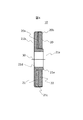
- FIG. 1 shows a schematic sectional view of an example of a double rotor type axial gap motor to which the present invention is applied.
- the motor 100 has a cylindrical stator 6 disposed along the inner peripheral surface of the housing 1 and faces each other so that the two disk-shaped rotors 10 sandwich a predetermined air gap in the rotation axis direction. Arranged.
- the rotor 10 is fixed to the rotating shaft 4 at the center of the disk.
- the rotating shaft 4 is disposed through the central portion of the cylindrical stator 6, and both ends are fixed to the bracket 2 via the bearing 3 so as to be rotatable.
- the bracket 2 is fixed in the vicinity of both opening ends of the substantially cylindrical housing 1.
- the stator 6 is configured by arranging a plurality of stator cores 7 at equal intervals in the circumferential direction around the rotating shaft 4.
- Each stator core 7 is provided with a bobbin (not shown) around which a stator coil 8 is wound.
- the stator core 7 and the stator coil 8 are molded with a mold resin 9.
- the rotor 10 includes a disk-shaped rotor base (base, base) 12 and a permanent magnet 11.
- the permanent magnet 11 may be a single annular magnet or may be divided into a plurality of pieces.
- the permanent magnet 11 is magnetized so that N poles and S poles are alternately positioned in the rotation axis direction and in the circumferential direction.
- the rotor base 12 may be a non-magnetic material or a yoke made of a magnetic material. Further, a yoke made of a magnetic material may be disposed between the non-magnetic rotor base 12 and the permanent magnet 11.
- the permanent magnet 11 is made of, for example, a rare earth magnet or a ferrite magnet.
- the permanent magnet 11 is attached to the rotor base 12 by a connecting member (not shown) such as an adhesive.
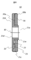
- FIG. 2A shows an example of an enlarged cross-sectional view of the rotor 10 of the present embodiment.
- the permanent magnet 20 is composed of an annular flat magnet having a uniform thickness, and includes a rotor base connection surface 20a and a stator facing surface 20b.
- the rotor base 21 includes a central rotating shaft portion 21a and an outer peripheral magnet support portion 21b.
- the rotary shaft 4 is fitted into the central hole of the rotary shaft portion 21a during assembly.
- the magnet support portion 21b that supports the permanent magnet 20 includes a permanent magnet connection surface 21c, to which the permanent magnet 20 is attached and held.
- symbol 21d shows the 1st shaft attachment reference surface which is a reference surface which attaches the shaft which is a jig
- the first shaft attachment reference surface is a cylindrical surface parallel to the rotation axis 30 and the rotation shaft is attached later.
- Reference numeral 21e denotes a second shaft attachment reference surface that is a reference surface to which a shaft that is a jig for attaching the permanent magnet 20 is attached.
- the second shaft attachment reference surface is a stator facing surface that is perpendicular to the rotation axis 30.
- the permanent magnet connection surface 21c of the rotor base 21 is designed as a plane perpendicular to the rotation axis 30, but may not be truly perpendicular to the rotation axis 30 due to processing errors.
- the example of FIG. 2A is an example in which the magnet support portion 21b is thin on the outer peripheral side of the rotor base 21 and the thickness on the center side also varies.
- the thickness of the connection member 22 such as an adhesive is changed in the radial direction and / or the circumferential direction according to the processing error, so that the stator facing surface 20b of the permanent magnet 20 is rotated along the rotation axis of the rotation axis. Be perpendicular to 30.
- connection member 22 such as an adhesive is applied to the permanent magnet connection surface 21c of the magnet support portion 21b. Then, the permanent magnet 20 is pressed toward the rotor base 21 parallel to the rotation axis 30 while keeping the stator facing surface 20 b of the permanent magnet 20 perpendicular to the rotation axis 30.
- connection member 22 such as an adhesive is pressed, the connection member 22 flows, and the interval between the permanent magnet connection surface 21c and the rotor base connection surface 20a is narrowed. Then, at the center side, the permanent magnet connection surface 21c and the rotor base connection surface 20a partially contact each other or when the predetermined time has elapsed, the pressing of the permanent magnet 20 is stopped, and the connection member 22 is cured in this state.
- FIG. 2A is an example in which the pressing of the permanent magnet 20 is stopped when a predetermined time has passed in a state where the permanent magnet connection surface 21c and the rotor base connection surface 20a are not in contact with each other. Therefore, the connection member 22 remains between the permanent magnet connection surface 21c and the rotor base connection surface 20a.
- 2B is an example in which the permanent magnet 20 is pressed until the permanent magnet connection surface 21c and the rotor base connection surface 20a partially contact each other.
- the permanent magnet connection surface 21c and the rotor base connection surface 20a may be in contact with each other, or may be connected with a connection member 22 such as an adhesive interposed therebetween.
- a shaft which is a jig on the rotor base 21 with reference to the first shaft attachment reference surface 21 d parallel to the rotation axis 30. (Not shown) is attached and the permanent magnet 20 is inserted using the shaft as a guide, or a shaft (not shown) as a jig on the rotor base with the second shaft attachment reference surface 21e perpendicular to the rotation axis 30 as a reference. And the permanent magnet 20 is inserted using the shaft as a guide.
- the permanent magnet 20 is kept pressed even after the rotor base permanent magnet connection surface 21c and the rotor base connection surface 20a of the permanent magnet partially contact each other, the permanent magnet is moved along the permanent magnet connection surface 21c of the rotor base 21. 20 is inclined, and the stator facing surface 20 b of the permanent magnet 20 is not perpendicular to the rotation axis 30.
- the variation in the thickness of the rotor base due to the processing error of the rotor base 21 is compensated for by changing the thickness of the connecting member 22 such as an adhesive, and the stator facing surface 20b of the permanent magnet 20 is compensated. Can be kept perpendicular to the axis of rotation 30.
- FIG. 3 shows another example of an enlarged cross-sectional view of the rotor 10 of this embodiment.
- the example of FIG. 3 is an example in which the thickness of the magnet support portion 21b is reduced on the inner peripheral side of the rotor base 21 and the thickness on the outer peripheral side also varies.
- the stator facing surface 20b of the permanent magnet 20 is rotated on the rotation axis 30 of the rotation axis. Perpendicular to. Specifically, the permanent magnet 20 is pressed toward the rotor base 21 parallel to the rotation axis 30 while keeping the stator facing surface 20 b of the permanent magnet 20 perpendicular to the rotation axis 30.
- the connection member 22 such as an adhesive is pressed, the connection member 22 flows, and the interval between the permanent magnet connection surface 21c and the rotor base connection surface 20a is narrowed.
- FIG. 3 shows an example in which the connection member 22 is cured in a state where the permanent magnet connection surface 21c and the rotor base connection surface 20a are not in contact with each other.
- FIG. 4 shows another example of an enlarged cross-sectional view of the rotor 10 of this embodiment.
- the example of FIG. 4 is an example in which the thickness of the magnet support portion 21b gradually decreases from one end on the outer peripheral side of the rotor base 21 toward the other end on the outer peripheral side.
- the stator facing surface 20b of the permanent magnet 20 is rotated on the rotation axis 30 of the rotation axis. Perpendicular to. Specifically, the permanent magnet 20 is pressed toward the rotor base 21 parallel to the rotation axis 30 while keeping the stator facing surface 20 b of the permanent magnet 20 perpendicular to the rotation axis 30.
- the connection member 22 such as an adhesive is pressed, the connection member 22 flows, and the interval between the permanent magnet connection surface 21c and the rotor base connection surface 20a is narrowed.
- FIG. 4 shows an example in which the connection member 22 is cured in a state where the permanent magnet connection surface 21c and the rotor base connection surface 20a are not in contact with each other.
- FIG. 5 shows another example of an enlarged cross-sectional view of the rotor 10 of this embodiment.
- the example of FIG. 5 is an example in which the permanent magnet connection surface 21c of the rotor base 21 is curved and has one or more irregularities.
- the thickness of the connecting member 22 such as an adhesive is changed according to the processing error, so that the stator facing surface 20b of the permanent magnet 20 is made perpendicular to the rotation axis 30 of the rotation shaft.
- the permanent magnet 20 is pressed toward the rotor base 21 parallel to the rotation axis 30 while keeping the stator facing surface 20 b of the permanent magnet 20 perpendicular to the rotation axis 30.
- the connection member 22 such as an adhesive is pressed, the connection member 22 flows, and the interval between the permanent magnet connection surface 21c and the rotor base connection surface 20a is narrowed.
- the permanent magnet connection surface 21c and the rotor base connection surface 20a partially contact each other or when the predetermined time has passed, the pressing of the permanent magnet 20 is stopped, and the connection is made in this state.
- the member 22 is cured and connected.
- FIG. 6 shows another example of an enlarged cross-sectional view of the rotor 10 of this embodiment.
- the example of FIG. 6 is an example in which the rotation axis of the rotor 10 is inclined, that is, an example in which the rotation axis 30 of the rotation shaft mounting hole provided in the central rotation shaft portion 21a of the rotor base 21 is inclined due to a processing error. .
- the stator facing surface 20b of the permanent magnet 20 is rotated on the rotation axis 30 of the rotation axis. Perpendicular to. Specifically, the permanent magnet 20 is pressed toward the rotor base 21 parallel to the rotation axis 30 while keeping the stator facing surface 20 b of the permanent magnet 20 perpendicular to the rotation axis 30.
- the connection member 22 such as an adhesive is pressed, the connection member 22 flows, and the interval between the permanent magnet connection surface 21c and the rotor base connection surface 20a is narrowed.
- FIG. 6 shows an example in which the connection member 22 is cured in a state where the permanent magnet connection surface 21c and the rotor base connection surface 20a are not in contact with each other.
- FIG. 7 shows another example of an enlarged cross-sectional view of the rotor 10 of this embodiment.
- the example of FIG. 7 is an example in which the thickness of the permanent magnet 20 is not uniform and the thickness gradually changes from one end to the other end.
- the stator facing surface 20b of the permanent magnet 20 is rotated on the rotation axis 30 of the rotation axis. Perpendicular to. Specifically, the permanent magnet 20 is pressed toward the rotor base 21 parallel to the rotation axis 30 while keeping the stator facing surface 20 b of the permanent magnet 20 perpendicular to the rotation axis 30.
- the connection member 22 such as an adhesive is pressed, the connection member 22 flows, and the interval between the permanent magnet connection surface 21c and the rotor base connection surface 20a is narrowed.
- FIG. 7 shows an example in which the connection member 22 is cured in a state where the permanent magnet connection surface 21c and the rotor base connection surface 20a are not in contact with each other.
- FIG. 8 shows another example of an enlarged sectional view of the rotor 10 of this embodiment.
- the example of FIG. 8 is an example in which the gap adjusting member 23 is inserted in the gap between the permanent magnet connection surface 21c and the rotor base connection surface 20a.
- the stator facing surface 20b of the permanent magnet 20 is rotated on the rotation axis 30 of the rotation axis. Perpendicular to. Specifically, the gap adjusting member 23 is disposed on the permanent magnet connection surface 21c of the magnet support portion 21b, and the connection member 22 such as an adhesive is applied. The permanent magnet 20 is pressed toward the rotor base 21 parallel to the rotation axis 30 while keeping the stator facing surface 20 b of the permanent magnet 20 perpendicular to the rotation axis 30.
- connection member 22 such as an adhesive
- the connection member 22 flows, and the interval between the permanent magnet connection surface 21c and the rotor base connection surface 20a is narrowed.
- the gap adjusting member 23 and the rotor base connecting surface 20a partially contact each other or when the predetermined time has elapsed, the pressing of the permanent magnet 20 is stopped, and the connecting member 22 is moved in this state. Cure and connect.
- FIG. 8 shows an example in which the connecting member 22 is cured in a state where the gap adjusting member 23 and the rotor base connecting surface 20a do not contact each other.
- stator facing surface 20b of the permanent magnet 20 can be made perpendicular to the rotation axis 30 of the rotation shaft, and the gap between the permanent magnet connection surface 21c and the rotor base connection surface 20a is set as a gap adjusting member. 23 can be adjusted.
- the thickness of the connecting member 22 such as an adhesive is changed by changing the thickness of the rotor base and the permanent magnet due to the processing error of the rotor base 21 and the permanent magnet 20.
- the processing error is compensated, the stator facing surface 20b of the permanent magnet 20 can be kept perpendicular to the rotation axis 30, and the distance between the stator facing surface of the permanent magnet constituting the rotor and the stator can be made uniform. .
- productivity improves and it can reduce manufacturing cost.
- a double rotor type motor has been described as an example.
- the present invention can also be applied to an axial gap type motor having another structure, for example, a single rotor type motor.
- it may be an electric motor or a generator.
Abstract
Provided is an axial gap type rotating electric machine in which the distance between the stator-facing surface of a permanent magnet constituting a rotor and a stator can be uniformed even if distortion and unevenness caused by a processing error are present in a rotor base, the permanent magnet, and the like. The axial gap type rotating electric machine is provided with a stator and at least one rotor facing the stator with a predetermined air gap interposed therebetween in the rotating shaft direction and is characterized in that: the rotor is provided with a rotor base, a magnet attached to the rotor base, and a connection member for connecting the magnet to the rotor base; the surface of the magnet facing the stator is vertical to the rotational axis line of the rotor; and the thickness of the connection member in the rotating shaft direction varies on the magnet-attached surface of the rotor base so that the surface of the magnet facing the stator becomes vertical to the rotational axis line of the rotor.
Description
本発明は、アキシャルギャップ型回転電機に関する。
The present invention relates to an axial gap type rotating electrical machine.
アキシャルギャップ型の回転電機は、円筒状の固定子(ステータ)と円盤状の回転子(ロータ)を回転軸方向に所定のエアギャップを介して対向して配置したものである。固定子は、ハウジングの内周方向に沿って配置した複数のコアと、これに巻き回したコイルから構成される。また、回転子は、周方向に交互に異なる磁極を配置した永久磁石と、これを支持するロータベースから構成される。
An axial gap type rotating electrical machine is formed by arranging a cylindrical stator (stator) and a disk-shaped rotor (rotor) so as to face each other with a predetermined air gap in the rotation axis direction. The stator includes a plurality of cores arranged along the inner peripheral direction of the housing and a coil wound around the cores. The rotor includes a permanent magnet in which different magnetic poles are alternately arranged in the circumferential direction, and a rotor base that supports the permanent magnet.
電動機(モータ)のトルクは、回転子と固定子の対向面であるギャップ面積に比例する。そのため、アキシャルギャップ型のモータは、回転子の大径化によりギャップ面積を拡大することができ、モータの高出力化、高効率化を図ることができる。したがって、一般に用いられている円筒状の固定子と回転子とが径方向に対向したラジアルギャップ型のモータに比較し、薄型、扁平化に向いている。
The torque of the motor (motor) is proportional to the gap area that is the opposing surface of the rotor and stator. Therefore, the axial gap type motor can increase the gap area by increasing the diameter of the rotor, and can increase the output and efficiency of the motor. Therefore, it is suitable for thinning and flattening compared to a radial gap type motor in which a generally used cylindrical stator and rotor are opposed to each other in the radial direction.
特許文献1には、アキシャルギャップ型回転電機において、磁石の接着面とヨークの接着面との隙間に介在する接着剤を容易に食み出させることを目的として、「固定子に対向配置された磁石と、磁石の被接着面が接着部材を介して接着固定された接着面を含む回転子側ヨークとを備え、回転子側ヨークを、被接着面および接着面間の接着部材が介在する隙間が接着面の一端部側へ向かってテーパー状となる形状に形成したことを特徴とする回転子。(要約参照)」が記載されている。
Patent Document 1 discloses that in an axial gap type rotating electrical machine, an “adjacent stator is disposed” for the purpose of easily extruding an adhesive interposed in a gap between a bonding surface of a magnet and a bonding surface of a yoke. A magnet and a rotor-side yoke including an adhesive surface in which the bonded surface of the magnet is bonded and fixed via an adhesive member, and the rotor-side yoke is disposed in the gap between the bonded surface and the bonded surface. Is formed into a taper shape toward one end of the bonding surface (see abstract).
しかしながら、特許文献1記載のアキシャルギャップ型回転電機は、磁石とヨークとの接着をより強固にするため、ヨークを回転軸線に対して斜めになるように対称に形成している。このヨーク形状は、接着剤をはみ出させることを目的としており、ヨークの加工誤差等の問題は考慮されていない。
However, in the axial gap type rotating electrical machine described in Patent Document 1, the yoke is formed symmetrically with respect to the rotation axis in order to further strengthen the adhesion between the magnet and the yoke. This yoke shape is intended to cause the adhesive to protrude, and problems such as processing errors of the yoke are not considered.
実際にアキシャルギャップ型回転電機を製造する際は、性能向上や回転のムラを防ぐなどのために、ロータを構成する永久磁石のステータ対向面とステータとの間隔を均一にする必要がある。そのために、永久磁石のステータ対向面を、回転軸の回転軸線に対して垂直にする必要がある。ロータにおいて、永久磁石はロータベースに押圧して接着剤などで取り付けられるが、ロータベースや永久磁石の表面は加工誤差などにより、必ずしも均一にはできず、歪みや凹凸が生じてしまう。このような部品を用いてステータとの間隔を均一に構成することは困難である。また、ロータベースなどの加工精度を上げると、加工時間が長くなり、生産性やコスト面の課題が生じる。
When actually manufacturing an axial gap type rotating electrical machine, it is necessary to make the distance between the stator facing surface of the permanent magnet and the stator uniform in order to improve performance and prevent uneven rotation. Therefore, it is necessary to make the stator facing surface of the permanent magnet perpendicular to the rotation axis of the rotation shaft. In the rotor, the permanent magnet is pressed against the rotor base and attached with an adhesive or the like, but the surface of the rotor base or the permanent magnet cannot always be made uniform due to a processing error or the like, and distortion or unevenness occurs. It is difficult to form a uniform distance from the stator using such components. In addition, if the processing accuracy of the rotor base and the like is increased, the processing time becomes longer, and productivity and cost issues arise.
このように、ロータベースや永久磁石などに加工誤差による歪み・凹凸があっても、ロータを構成する永久磁石のステータ対向面とステータとの間隔を均一にすることができるアキシャルギャップ型回転電機を提供することが望まれる。
As described above, an axial gap type rotating electrical machine that can make the gap between the stator facing surface of the permanent magnet and the stator uniform even if the rotor base, permanent magnet, etc. are distorted or uneven due to processing errors. It is desirable to provide.
上記課題を解決するために、請求の範囲に記載の構成を採用する。
In order to solve the above problems, the configuration described in the claims is adopted.
本発明は、上記課題を解決する手段を複数含んでいるが、本発明のアキシャルギャップ型回転電機の一例を挙げるならば、
ステータと、該ステータと回転軸方向に所定のエアギャップを介して対向する少なくとも1つのロータとを備えるアキシャルギャップ型回転電機であって、
前記ロータは、ロータベースと、該ロータベースに取り付けられる磁石と、前記磁石を前記ロータベースに接続する接続部材とを備え、前記磁石の前記ステータと対向する面は、ロータの回転軸線に対して垂直であり、前記接続部材の回転軸方向の厚さは、前記磁石の前記ステータと対向する面がロータの回転軸線に対して垂直となるように、前記ロータベースの磁石の取付面上で変化していることを特徴とするものである。 The present invention includes a plurality of means for solving the above-described problems. If an example of the axial gap type rotating electrical machine of the present invention is given,
An axial gap type rotating electrical machine comprising a stator and at least one rotor facing the stator with a predetermined air gap in the rotation axis direction,
The rotor includes a rotor base, a magnet attached to the rotor base, and a connection member that connects the magnet to the rotor base, and a surface of the magnet that faces the stator has a rotation axis of the rotor. The thickness of the connecting member in the rotation axis direction varies on the mounting surface of the rotor base magnet so that the surface of the magnet facing the stator is perpendicular to the rotation axis of the rotor. It is characterized by that.
本発明によれば、ロータベースや永久磁石などに加工誤差があっても、ロータを構成する永久磁石のステータ対向面とステータとの間隔を均一にすることができる。また、ロータベースや永久磁石などの加工精度を上げる必要がないので、生産性が向上し、製造コストを低減することができる。
According to the present invention, even if there is a processing error in the rotor base, permanent magnet, etc., the distance between the stator facing surface of the permanent magnet constituting the rotor and the stator can be made uniform. In addition, since it is not necessary to increase the processing accuracy of the rotor base and permanent magnet, productivity can be improved and manufacturing cost can be reduced.
上述した以外の課題、構成及び効果は、以下の実施形態の説明により明らかにされる。
Issues, configurations, and effects other than those described above will be clarified by the description of the following embodiments.
以下、図面を用いて、本発明を実施するための形態を説明する。以下の説明は本発明の内容の具体例を示すものであり、本発明がこれらの説明に限定されるものではなく、本明細書に開示される技術的思想の範囲内において、当業者による様々な変更及び修正が可能である。また、本発明を説明するための全図において、同一の機能を有するものは、同一の符号を付け、その繰り返しの説明は省略する。
Hereinafter, embodiments for carrying out the present invention will be described with reference to the drawings. The following description shows specific examples of the contents of the present invention, and the present invention is not limited to these descriptions. Various modifications by those skilled in the art are within the scope of the technical idea disclosed in this specification. Changes and modifications are possible. Further, in all the drawings for explaining the present invention, those having the same function are denoted by the same reference numerals, and repeated description thereof is omitted.
図1に、本発明を適用した、ダブルロータ型のアキシャルギャップ型モータの一例の概略断面図を示す。
FIG. 1 shows a schematic sectional view of an example of a double rotor type axial gap motor to which the present invention is applied.
モータ100は、ハウジング1の内周面に沿って配置された円筒状のステータ6を、円盤状の2つのロータ10が、回転軸方向に所定のエアギャップを介して挟むように、各々面対向して配置される。ロータ10は、円盤中央が回転軸4に固定されている。回転軸4は、円筒状のステータ6の中央部分を貫通して配置され、両端部が軸受3を介してブラケット2に回転可能に固定されている。ブラケット2は、概略円筒形のハウジング1の両開口端部付近に固定されている。
The motor 100 has a cylindrical stator 6 disposed along the inner peripheral surface of the housing 1 and faces each other so that the two disk-shaped rotors 10 sandwich a predetermined air gap in the rotation axis direction. Arranged. The rotor 10 is fixed to the rotating shaft 4 at the center of the disk. The rotating shaft 4 is disposed through the central portion of the cylindrical stator 6, and both ends are fixed to the bracket 2 via the bearing 3 so as to be rotatable. The bracket 2 is fixed in the vicinity of both opening ends of the substantially cylindrical housing 1.
ステータ6は、回転軸4を中心として、複数のステータコア7を円周方向に等間隔に配置して構成されている。それぞれのステータコア7には、ステータコイル8を巻き回したボビン(図示せず)が設けられ、ステータコア7とステータコイル8は、モールド樹脂9でモールド成形されている。
The stator 6 is configured by arranging a plurality of stator cores 7 at equal intervals in the circumferential direction around the rotating shaft 4. Each stator core 7 is provided with a bobbin (not shown) around which a stator coil 8 is wound. The stator core 7 and the stator coil 8 are molded with a mold resin 9.
ロータ10は、円盤状のロータベース(基台、基部)12と、永久磁石11から構成されている。永久磁石11は、1枚の環状の磁石でも良いし、複数に分割されていても良い。永久磁石11は、回転軸方向に、かつ、周方向にN極とS極とが交互に位置するように着磁されている。ロータベース12は、非磁性体でも、或いは、磁性体から成るヨーク(継鉄)でも良い。また、非磁性体のロータベース12と永久磁石11との間に、磁性体から成るヨークを配置しても良い。永久磁石11は、例えば希土類磁石、フェライト磁石などから成る。永久磁石11は、ロータベース12に接着剤等の接続部材(図示せず)により取り付けられる。
The rotor 10 includes a disk-shaped rotor base (base, base) 12 and a permanent magnet 11. The permanent magnet 11 may be a single annular magnet or may be divided into a plurality of pieces. The permanent magnet 11 is magnetized so that N poles and S poles are alternately positioned in the rotation axis direction and in the circumferential direction. The rotor base 12 may be a non-magnetic material or a yoke made of a magnetic material. Further, a yoke made of a magnetic material may be disposed between the non-magnetic rotor base 12 and the permanent magnet 11. The permanent magnet 11 is made of, for example, a rare earth magnet or a ferrite magnet. The permanent magnet 11 is attached to the rotor base 12 by a connecting member (not shown) such as an adhesive.
図2Aに、本実施例のロータ10の拡大断面図の一例を示す。永久磁石20は、環状で均一な厚さの平板磁石から成り、ロータベース接続面20aとステータ対向面20bを備えている。ロータベース21は、中央の回転軸部21aと、その外周側の磁石支持部21bを備えている。回転軸部21aの中心孔には、組立時に回転軸4が嵌め込まれる。永久磁石20を支持する磁石支持部21bは、永久磁石接続面21cを備えており、ここに永久磁石20が取り付けられ、保持する。
FIG. 2A shows an example of an enlarged cross-sectional view of the rotor 10 of the present embodiment. The permanent magnet 20 is composed of an annular flat magnet having a uniform thickness, and includes a rotor base connection surface 20a and a stator facing surface 20b. The rotor base 21 includes a central rotating shaft portion 21a and an outer peripheral magnet support portion 21b. The rotary shaft 4 is fitted into the central hole of the rotary shaft portion 21a during assembly. The magnet support portion 21b that supports the permanent magnet 20 includes a permanent magnet connection surface 21c, to which the permanent magnet 20 is attached and held.
なお、符号21dは、永久磁石20を取り付ける際の治具であるシャフトを取り付ける基準面である、第1のシャフト取付基準面を示す。第1のシャフト取付基準面は、回転軸線30に平行な円筒面であり、後に回転軸が取り付けられる。また、符号21eは、永久磁石20を取り付ける際の治具であるシャフトを取り付ける基準面である、第2のシャフト取付基準面を示す。第2のシャフト取付基準面は、回転軸線30に垂直な、ステータ対向面である。
In addition, the code | symbol 21d shows the 1st shaft attachment reference surface which is a reference surface which attaches the shaft which is a jig | tool at the time of attaching the permanent magnet 20. As shown in FIG. The first shaft attachment reference surface is a cylindrical surface parallel to the rotation axis 30 and the rotation shaft is attached later. Reference numeral 21e denotes a second shaft attachment reference surface that is a reference surface to which a shaft that is a jig for attaching the permanent magnet 20 is attached. The second shaft attachment reference surface is a stator facing surface that is perpendicular to the rotation axis 30.
ロータベース21の永久磁石接続面21cは、回転軸線30に垂直な平面として設計されるが、加工誤差により、回転軸線30に対して真に垂直とはならないことがある。図2Aの例は、ロータベース21の外周側で、磁石支持部21bの厚さが薄くなるとともに、中心側の厚さにもバラツキがある例である。
The permanent magnet connection surface 21c of the rotor base 21 is designed as a plane perpendicular to the rotation axis 30, but may not be truly perpendicular to the rotation axis 30 due to processing errors. The example of FIG. 2A is an example in which the magnet support portion 21b is thin on the outer peripheral side of the rotor base 21 and the thickness on the center side also varies.
アキシャルギャップ型モータにおいては、性能向上や回転のムラを防ぐなどのために、ロータを構成する永久磁石20のステータ対向面20bとステータとの間隔を均一にする必要がある。そのために、永久磁石20のステータ対向面20bを、回転軸の回転軸線30に対して垂直にする必要がある。本実施例では、接着剤等の接続部材22の厚さを、加工誤差に応じて、径方向及び/又は周方向で変えることで、永久磁石20のステータ対向面20bを、回転軸の回転軸線30に対して垂直にする。
In the axial gap type motor, it is necessary to make the distance between the stator facing surface 20b of the permanent magnet 20 constituting the rotor and the stator uniform in order to improve performance and prevent uneven rotation. Therefore, it is necessary to make the stator facing surface 20b of the permanent magnet 20 perpendicular to the rotation axis 30 of the rotation shaft. In the present embodiment, the thickness of the connection member 22 such as an adhesive is changed in the radial direction and / or the circumferential direction according to the processing error, so that the stator facing surface 20b of the permanent magnet 20 is rotated along the rotation axis of the rotation axis. Be perpendicular to 30.
詳細には、磁石支持部21bの永久磁石接続面21cに、接着剤等の接続部材22を塗布する。そして、永久磁石20のステータ対向面20bを回転軸線30に対して垂直に保ちつつ、永久磁石20を回転軸線30に平行にロータベース21に向けて押圧する。接着剤等の接続部材22が押圧されると、接続部材22が流動して、永久磁石接続面21cとロータベース接続面20aとの間隔が狭まる。そして、中央側において、永久磁石接続面21cとロータベース接続面20aとが一部で接触するか或いは所定時間が経過したところで永久磁石20の押圧を止め、この状態で接続部材22を硬化して接続する。図2Aの例は、永久磁石接続面21cとロータベース接続面20aとが接触しない状態で、永久磁石20の押圧を所定時間が経過したところで止めた例である。そのため、永久磁石接続面21cとロータベース接続面20aとの間に接続部材22が残っている。これに対し、図2Bのロータ10の拡大断面図の例は、永久磁石接続面21cとロータベース接続面20aとが一部で接触するまで永久磁石20を押圧した例である。本発明において、永久磁石接続面21cとロータベース接続面20aとが一部で接触していても或いは両者の間に接着剤等の接続部材22が介在して接続されていても、良い。
Specifically, a connection member 22 such as an adhesive is applied to the permanent magnet connection surface 21c of the magnet support portion 21b. Then, the permanent magnet 20 is pressed toward the rotor base 21 parallel to the rotation axis 30 while keeping the stator facing surface 20 b of the permanent magnet 20 perpendicular to the rotation axis 30. When the connection member 22 such as an adhesive is pressed, the connection member 22 flows, and the interval between the permanent magnet connection surface 21c and the rotor base connection surface 20a is narrowed. Then, at the center side, the permanent magnet connection surface 21c and the rotor base connection surface 20a partially contact each other or when the predetermined time has elapsed, the pressing of the permanent magnet 20 is stopped, and the connection member 22 is cured in this state. Connecting. The example of FIG. 2A is an example in which the pressing of the permanent magnet 20 is stopped when a predetermined time has passed in a state where the permanent magnet connection surface 21c and the rotor base connection surface 20a are not in contact with each other. Therefore, the connection member 22 remains between the permanent magnet connection surface 21c and the rotor base connection surface 20a. 2B is an example in which the permanent magnet 20 is pressed until the permanent magnet connection surface 21c and the rotor base connection surface 20a partially contact each other. In the present invention, the permanent magnet connection surface 21c and the rotor base connection surface 20a may be in contact with each other, or may be connected with a connection member 22 such as an adhesive interposed therebetween.
永久磁石20のステータ対向面20bを回転軸線30に対して垂直に保つには、例えば、回転軸線30に平行な第1のシャフト取付基準面21dを基準として、ロータベース21に治具であるシャフト(図示せず)を取り付け、シャフトを案内として永久磁石20を挿入する、或いは、回転軸線30に垂直な第2のシャフト取付基準面21eを基準として、ロータベースに治具であるシャフト(図示せず)を取り付け、シャフトを案内として永久磁石20を挿入すれば、良い。
In order to keep the stator facing surface 20 b of the permanent magnet 20 perpendicular to the rotation axis 30, for example, a shaft which is a jig on the rotor base 21 with reference to the first shaft attachment reference surface 21 d parallel to the rotation axis 30. (Not shown) is attached and the permanent magnet 20 is inserted using the shaft as a guide, or a shaft (not shown) as a jig on the rotor base with the second shaft attachment reference surface 21e perpendicular to the rotation axis 30 as a reference. And the permanent magnet 20 is inserted using the shaft as a guide.
ロータベースの永久磁石接続面21cと永久磁石のロータベース接続面20aとが一部で接触した後も、永久磁石20を押圧し続けると、ロータベース21の永久磁石接続面21cに沿って永久磁石20が傾き、永久磁石20のステータ対向面20bが回転軸線30に対して垂直でなくなる。
If the permanent magnet 20 is kept pressed even after the rotor base permanent magnet connection surface 21c and the rotor base connection surface 20a of the permanent magnet partially contact each other, the permanent magnet is moved along the permanent magnet connection surface 21c of the rotor base 21. 20 is inclined, and the stator facing surface 20 b of the permanent magnet 20 is not perpendicular to the rotation axis 30.
本実施例では、ロータベース21の加工誤差によるロータベースの厚さのバラツキを、接着剤等の接続部材22の厚さを変えることにより、加工誤差を補償し、永久磁石20のステータ対向面20bを回転軸線30に対して垂直に保つことができる。
In this embodiment, the variation in the thickness of the rotor base due to the processing error of the rotor base 21 is compensated for by changing the thickness of the connecting member 22 such as an adhesive, and the stator facing surface 20b of the permanent magnet 20 is compensated. Can be kept perpendicular to the axis of rotation 30.
図3に、本実施例のロータ10の拡大断面図の他の一例を示す。図3の例は、ロータベース21の内周側で、磁石支持部21bの厚さが薄くなるとともに、外周側の厚さにもバラツキがある例である。
FIG. 3 shows another example of an enlarged cross-sectional view of the rotor 10 of this embodiment. The example of FIG. 3 is an example in which the thickness of the magnet support portion 21b is reduced on the inner peripheral side of the rotor base 21 and the thickness on the outer peripheral side also varies.
本例でも、接着剤等の接続部材22の厚さを、加工誤差に応じて、径方向及び/又は周方向で変えることで、永久磁石20のステータ対向面20bを、回転軸の回転軸線30に対して垂直にする。詳細には、永久磁石20のステータ対向面20bを回転軸線30に対して垂直に保ちつつ、永久磁石20を回転軸線30に平行にロータベース21に向けて押圧する。接着剤等の接続部材22が押圧されると、接続部材22が流動して、永久磁石接続面21cとロータベース接続面20aとの間隔が狭まる。そして、ロータベース21の外周側において、永久磁石接続面21cとロータベース接続面20aとが一部で接触するか或いは所定時間が経過したところで永久磁石20の押圧を止め、この状態で接続部材22を硬化して接続する。図3は、永久磁石接続面21cとロータベース接続面20aとが接触しない状態で接続部材22を硬化した例を示す。
Also in this example, by changing the thickness of the connection member 22 such as an adhesive in the radial direction and / or the circumferential direction in accordance with a processing error, the stator facing surface 20b of the permanent magnet 20 is rotated on the rotation axis 30 of the rotation axis. Perpendicular to. Specifically, the permanent magnet 20 is pressed toward the rotor base 21 parallel to the rotation axis 30 while keeping the stator facing surface 20 b of the permanent magnet 20 perpendicular to the rotation axis 30. When the connection member 22 such as an adhesive is pressed, the connection member 22 flows, and the interval between the permanent magnet connection surface 21c and the rotor base connection surface 20a is narrowed. Then, on the outer peripheral side of the rotor base 21, the permanent magnet connection surface 21c and the rotor base connection surface 20a partially contact each other or when the predetermined time has passed, the pressing of the permanent magnet 20 is stopped, and in this state, the connection member 22 Cure and connect. FIG. 3 shows an example in which the connection member 22 is cured in a state where the permanent magnet connection surface 21c and the rotor base connection surface 20a are not in contact with each other.
図4に、本実施例のロータ10の拡大断面図の他の一例を示す。図4の例は、ロータベース21の外周側の一端から外周側の他端に向かって次第に、磁石支持部21bの厚さが薄くなる例である。
FIG. 4 shows another example of an enlarged cross-sectional view of the rotor 10 of this embodiment. The example of FIG. 4 is an example in which the thickness of the magnet support portion 21b gradually decreases from one end on the outer peripheral side of the rotor base 21 toward the other end on the outer peripheral side.
本例でも、接着剤等の接続部材22の厚さを、加工誤差に応じて、径方向及び/又は周方向で変えることで、永久磁石20のステータ対向面20bを、回転軸の回転軸線30に対して垂直にする。詳細には、永久磁石20のステータ対向面20bを回転軸線30に対して垂直に保ちつつ、永久磁石20を回転軸線30に平行にロータベース21に向けて押圧する。接着剤等の接続部材22が押圧されると、接続部材22が流動して、永久磁石接続面21cとロータベース接続面20aとの間隔が狭まる。そして、ロータベース21の外周側の一端において、永久磁石接続面21cとロータベース接続面20aとが一部で接触するか或いは所定時間が経過したところで永久磁石20の押圧を止め、この状態で接続部材22を硬化して接続する。図4は、永久磁石接続面21cとロータベース接続面20aとが接触しない状態で接続部材22を硬化した例を示す。
Also in this example, by changing the thickness of the connection member 22 such as an adhesive in the radial direction and / or the circumferential direction in accordance with a processing error, the stator facing surface 20b of the permanent magnet 20 is rotated on the rotation axis 30 of the rotation axis. Perpendicular to. Specifically, the permanent magnet 20 is pressed toward the rotor base 21 parallel to the rotation axis 30 while keeping the stator facing surface 20 b of the permanent magnet 20 perpendicular to the rotation axis 30. When the connection member 22 such as an adhesive is pressed, the connection member 22 flows, and the interval between the permanent magnet connection surface 21c and the rotor base connection surface 20a is narrowed. Then, at one end on the outer peripheral side of the rotor base 21, the permanent magnet connection surface 21c and the rotor base connection surface 20a partially contact each other or when the predetermined time has passed, the pressing of the permanent magnet 20 is stopped, and the connection is made in this state. The member 22 is cured and connected. FIG. 4 shows an example in which the connection member 22 is cured in a state where the permanent magnet connection surface 21c and the rotor base connection surface 20a are not in contact with each other.
図5に、本実施例のロータ10の拡大断面図の他の一例を示す。図5の例は、ロータベース21の永久磁石接続面21cが湾曲し、1つ或いは複数の凹凸を備える例である。
FIG. 5 shows another example of an enlarged cross-sectional view of the rotor 10 of this embodiment. The example of FIG. 5 is an example in which the permanent magnet connection surface 21c of the rotor base 21 is curved and has one or more irregularities.
本例でも、接着剤等の接続部材22の厚さを、加工誤差に応じて変えることで、永久磁石20のステータ対向面20bを、回転軸の回転軸線30に対して垂直にする。詳細には、永久磁石20のステータ対向面20bを回転軸線30に対して垂直に保ちつつ、永久磁石20を回転軸線30に平行にロータベース21に向けて押圧する。接着剤等の接続部材22が押圧されると、接続部材22が流動して、永久磁石接続面21cとロータベース接続面20aとの間隔が狭まる。そして、ロータベース21の湾曲した凸部において、永久磁石接続面21cとロータベース接続面20aとが一部で接触するか或いは所定時間が経過したところで永久磁石20の押圧を止め、この状態で接続部材22を硬化して接続する。
Also in this example, the thickness of the connecting member 22 such as an adhesive is changed according to the processing error, so that the stator facing surface 20b of the permanent magnet 20 is made perpendicular to the rotation axis 30 of the rotation shaft. Specifically, the permanent magnet 20 is pressed toward the rotor base 21 parallel to the rotation axis 30 while keeping the stator facing surface 20 b of the permanent magnet 20 perpendicular to the rotation axis 30. When the connection member 22 such as an adhesive is pressed, the connection member 22 flows, and the interval between the permanent magnet connection surface 21c and the rotor base connection surface 20a is narrowed. Then, in the curved convex portion of the rotor base 21, the permanent magnet connection surface 21c and the rotor base connection surface 20a partially contact each other or when the predetermined time has passed, the pressing of the permanent magnet 20 is stopped, and the connection is made in this state. The member 22 is cured and connected.
図6に、本実施例のロータ10の拡大断面図の他の一例を示す。図6の例は、ロータ10の回転軸が傾いた例、即ち、ロータベース21の中央の回転軸部21aに設けた回転軸取付用の孔の回転軸線30が加工誤差により傾いた例である。
FIG. 6 shows another example of an enlarged cross-sectional view of the rotor 10 of this embodiment. The example of FIG. 6 is an example in which the rotation axis of the rotor 10 is inclined, that is, an example in which the rotation axis 30 of the rotation shaft mounting hole provided in the central rotation shaft portion 21a of the rotor base 21 is inclined due to a processing error. .
本例でも、接着剤等の接続部材22の厚さを、加工誤差に応じて、径方向及び/又は周方向で変えることで、永久磁石20のステータ対向面20bを、回転軸の回転軸線30に対して垂直にする。詳細には、永久磁石20のステータ対向面20bを回転軸線30に対して垂直に保ちつつ、永久磁石20を回転軸線30に平行にロータベース21に向けて押圧する。接着剤等の接続部材22が押圧されると、接続部材22が流動して、永久磁石接続面21cとロータベース接続面20aとの間隔が狭まる。そして、ロータベース21の一端において、永久磁石接続面21cとロータベース接続面20aとが一部で接触するか或いは所定時間が経過したところで永久磁石20の押圧を止め、この状態で接続部材22を硬化して接続する。図6は、永久磁石接続面21cとロータベース接続面20aとが接触しない状態で接続部材22を硬化した例を示す。
Also in this example, by changing the thickness of the connection member 22 such as an adhesive in the radial direction and / or the circumferential direction in accordance with a processing error, the stator facing surface 20b of the permanent magnet 20 is rotated on the rotation axis 30 of the rotation axis. Perpendicular to. Specifically, the permanent magnet 20 is pressed toward the rotor base 21 parallel to the rotation axis 30 while keeping the stator facing surface 20 b of the permanent magnet 20 perpendicular to the rotation axis 30. When the connection member 22 such as an adhesive is pressed, the connection member 22 flows, and the interval between the permanent magnet connection surface 21c and the rotor base connection surface 20a is narrowed. Then, at one end of the rotor base 21, the permanent magnet connection surface 21c and the rotor base connection surface 20a partially contact each other or when the predetermined time has elapsed, the pressing of the permanent magnet 20 is stopped, and the connection member 22 is moved in this state. Cure and connect. FIG. 6 shows an example in which the connection member 22 is cured in a state where the permanent magnet connection surface 21c and the rotor base connection surface 20a are not in contact with each other.
図7に、本実施例のロータ10の拡大断面図の他の一例を示す。図7の例は、永久磁石20の厚さが不均一で、一端から他端へ向かって厚さが次第に変化する例である。
FIG. 7 shows another example of an enlarged cross-sectional view of the rotor 10 of this embodiment. The example of FIG. 7 is an example in which the thickness of the permanent magnet 20 is not uniform and the thickness gradually changes from one end to the other end.
本例でも、接着剤等の接続部材22の厚さを、加工誤差に応じて、径方向及び/又は周方向で変えることで、永久磁石20のステータ対向面20bを、回転軸の回転軸線30に対して垂直にする。詳細には、永久磁石20のステータ対向面20bを回転軸線30に対して垂直に保ちつつ、永久磁石20を回転軸線30に平行にロータベース21に向けて押圧する。接着剤等の接続部材22が押圧されると、接続部材22が流動して、永久磁石接続面21cとロータベース接続面20aとの間隔が狭まる。そして、永久磁石20の一端において、永久磁石接続面21cとロータベース接続面20aとが一部で接触するか或いは所定時間が経過したところで永久磁石20の押圧を止め、この状態で接続部材22を硬化して接続する。図7は、永久磁石接続面21cとロータベース接続面20aとが接触しない状態で接続部材22を硬化した例を示す。
Also in this example, by changing the thickness of the connection member 22 such as an adhesive in the radial direction and / or the circumferential direction in accordance with a processing error, the stator facing surface 20b of the permanent magnet 20 is rotated on the rotation axis 30 of the rotation axis. Perpendicular to. Specifically, the permanent magnet 20 is pressed toward the rotor base 21 parallel to the rotation axis 30 while keeping the stator facing surface 20 b of the permanent magnet 20 perpendicular to the rotation axis 30. When the connection member 22 such as an adhesive is pressed, the connection member 22 flows, and the interval between the permanent magnet connection surface 21c and the rotor base connection surface 20a is narrowed. Then, at one end of the permanent magnet 20, the permanent magnet connection surface 21c and the rotor base connection surface 20a partially contact each other or when the predetermined time has elapsed, the pressing of the permanent magnet 20 is stopped, and the connection member 22 is moved in this state. Cure and connect. FIG. 7 shows an example in which the connection member 22 is cured in a state where the permanent magnet connection surface 21c and the rotor base connection surface 20a are not in contact with each other.
図8に、本実施例のロータ10の拡大断面図の他の一例を示す。図8の例は、永久磁石接続面21cとロータベース接続面20aとの間隙に隙間調整部材23を入れた例である。
FIG. 8 shows another example of an enlarged sectional view of the rotor 10 of this embodiment. The example of FIG. 8 is an example in which the gap adjusting member 23 is inserted in the gap between the permanent magnet connection surface 21c and the rotor base connection surface 20a.
本例でも、接着剤等の接続部材22の厚さを、加工誤差に応じて、径方向及び/又は周方向で変えることで、永久磁石20のステータ対向面20bを、回転軸の回転軸線30に対して垂直にする。詳細には、磁石支持部21bの永久磁石接続面21cに、隙間調整部材23を配置し、接着剤等の接続部材22を塗布する。永久磁石20のステータ対向面20bを回転軸線30に対して垂直に保ちつつ、永久磁石20を回転軸線30に平行にロータベース21に向けて押圧する。接着剤等の接続部材22が押圧されると、接続部材22が流動して、永久磁石接続面21cとロータベース接続面20aとの間隔が狭まる。そして、隙間調整部材23のところにおいて、隙間調整部材23とロータベース接続面20aとが一部で接触するか或いは所定時間が経過したところで永久磁石20の押圧を止め、この状態で接続部材22を硬化して接続する。図8は、隙間調整部材23とロータベース接続面20aとが接触しない状態で接続部材22を硬化した例を示す。
Also in this example, by changing the thickness of the connection member 22 such as an adhesive in the radial direction and / or the circumferential direction in accordance with a processing error, the stator facing surface 20b of the permanent magnet 20 is rotated on the rotation axis 30 of the rotation axis. Perpendicular to. Specifically, the gap adjusting member 23 is disposed on the permanent magnet connection surface 21c of the magnet support portion 21b, and the connection member 22 such as an adhesive is applied. The permanent magnet 20 is pressed toward the rotor base 21 parallel to the rotation axis 30 while keeping the stator facing surface 20 b of the permanent magnet 20 perpendicular to the rotation axis 30. When the connection member 22 such as an adhesive is pressed, the connection member 22 flows, and the interval between the permanent magnet connection surface 21c and the rotor base connection surface 20a is narrowed. At the gap adjusting member 23, the gap adjusting member 23 and the rotor base connecting surface 20a partially contact each other or when the predetermined time has elapsed, the pressing of the permanent magnet 20 is stopped, and the connecting member 22 is moved in this state. Cure and connect. FIG. 8 shows an example in which the connecting member 22 is cured in a state where the gap adjusting member 23 and the rotor base connecting surface 20a do not contact each other.
本実施例では、永久磁石20のステータ対向面20bを、回転軸の回転軸線30に対して垂直にすることができるとともに、永久磁石接続面21cとロータベース接続面20aとの間隔を隙間調整部材23で調節することができる。
In the present embodiment, the stator facing surface 20b of the permanent magnet 20 can be made perpendicular to the rotation axis 30 of the rotation shaft, and the gap between the permanent magnet connection surface 21c and the rotor base connection surface 20a is set as a gap adjusting member. 23 can be adjusted.
上記のとおり、本実施例によれば、ロータベース21や永久磁石20の加工誤差によるロータベースや永久磁石の厚さのばらつきなどを、接着剤等の接続部材22の厚さを変えることにより、加工誤差を補償し、永久磁石20のステータ対向面20bを回転軸線30に対して垂直に保つことができ、ロータを構成する永久磁石のステータ対向面とステータとの間隔を均一にすることができる。そして、ロータベースや永久磁石などの加工精度を上げる必要がないので、生産性が向上し、製造コストを低減することができる。
As described above, according to the present embodiment, the thickness of the connecting member 22 such as an adhesive is changed by changing the thickness of the rotor base and the permanent magnet due to the processing error of the rotor base 21 and the permanent magnet 20. The processing error is compensated, the stator facing surface 20b of the permanent magnet 20 can be kept perpendicular to the rotation axis 30, and the distance between the stator facing surface of the permanent magnet constituting the rotor and the stator can be made uniform. . And since it is not necessary to raise processing precision, such as a rotor base and a permanent magnet, productivity improves and it can reduce manufacturing cost.
なお、本実施例では、ダブルロータ型のモータを例として説明したが、他構造のアキシャルギャップ型モータ、例えばシングルロータ型のモータに適用することもできる。更には、電動機であっても発電機であっても良い。
In the present embodiment, a double rotor type motor has been described as an example. However, the present invention can also be applied to an axial gap type motor having another structure, for example, a single rotor type motor. Furthermore, it may be an electric motor or a generator.
1 ハウジング
2 ブラケット
3 軸受
4 回転軸
6 ステータ
7 ステータコア
8 ステータコイル
9 モールド樹脂
10 ロータ
11 永久磁石
12 ロータベース
20 永久磁石
20a ロータベース接続面
20b ステータ対向面
21 ロータベース
21a 回転軸部
21b 磁石支持部
21c 永久磁石接続面
21d 第1のシャフト取付基準面
21e 第2のシャフト取付基準面
22 接続部材
23 隙間調整部材
30 回転軸線
100 モータ。 DESCRIPTION OF SYMBOLS 1Housing 2 Bracket 3 Bearing 4 Rotating shaft 6 Stator 7 Stator core 8 Stator coil 9 Mold resin 10 Rotor 11 Permanent magnet 12 Rotor base 20 Permanent magnet 20a Rotor base connection surface 20b Stator facing surface 21 Rotor base 21a Rotating shaft portion 21b Magnet support portion 21c Permanent magnet connection surface 21d First shaft attachment reference surface 21e Second shaft attachment reference surface 22 Connection member 23 Gap adjustment member 30 Rotation axis 100 Motor.
2 ブラケット
3 軸受
4 回転軸
6 ステータ
7 ステータコア
8 ステータコイル
9 モールド樹脂
10 ロータ
11 永久磁石
12 ロータベース
20 永久磁石
20a ロータベース接続面
20b ステータ対向面
21 ロータベース
21a 回転軸部
21b 磁石支持部
21c 永久磁石接続面
21d 第1のシャフト取付基準面
21e 第2のシャフト取付基準面
22 接続部材
23 隙間調整部材
30 回転軸線
100 モータ。 DESCRIPTION OF SYMBOLS 1
Claims (10)
- ステータと、該ステータと回転軸方向に所定のエアギャップを介して対向する少なくとも1つのロータとを備えるアキシャルギャップ型回転電機であって、
前記ロータは、ロータベースと、該ロータベースに取り付けられる磁石と、前記磁石を前記ロータベースに接続する接続部材とを備え、
前記磁石の前記ステータと対向する面は、ロータの回転軸線に対して垂直であり、
前記接続部材の回転軸方向の厚さは、前記磁石の前記ステータと対向する面がロータの回転軸線に対して垂直となるように、前記ロータベースの磁石の取付面上で変化していることを特徴とするアキシャルギャップ型回転電機。 An axial gap type rotating electrical machine comprising a stator and at least one rotor facing the stator with a predetermined air gap in the rotation axis direction,
The rotor includes a rotor base, a magnet attached to the rotor base, and a connection member that connects the magnet to the rotor base,
The surface of the magnet facing the stator is perpendicular to the rotational axis of the rotor;
The thickness of the connecting member in the rotation axis direction varies on the mounting surface of the rotor base magnet so that the surface of the magnet facing the stator is perpendicular to the rotation axis of the rotor. An axial gap type rotating electrical machine characterized by - 請求項1に記載のアキシャルギャップ型回転電機において、
前記接続部材は、接着剤であることを特徴とするアキシャルギャップ型回転電機。 In the axial gap type rotating electrical machine according to claim 1,
The axial gap type rotating electrical machine, wherein the connecting member is an adhesive. - 請求項1に記載のアキシャルギャップ型回転電機において、
前記ロータベースの磁石の取付面は、ロータの回転軸線に対してほぼ垂直であることを特徴とするアキシャルギャップ型回転電機。 In the axial gap type rotating electrical machine according to claim 1,
The axial gap type rotating electric machine according to claim 1, wherein a mounting surface of the rotor base magnet is substantially perpendicular to a rotation axis of the rotor. - 請求項1に記載のアキシャルギャップ型回転電機において、
前記接続部材の回転軸方向の厚さは、前記ロータベースの磁石の取付面や磁石の表面の加工誤差を吸収するように、前記ロータベースの磁石の取付面上で変化していることを特徴とするアキシャルギャップ型回転電機。 In the axial gap type rotating electrical machine according to claim 1,
The thickness of the connecting member in the rotation axis direction varies on the mounting surface of the rotor base magnet so as to absorb processing errors on the mounting surface of the rotor base magnet and the surface of the magnet. Axial gap type rotating electrical machine. - 請求項1に記載のアキシャルギャップ型回転電機において、
前記磁石の前記ステータと対向する面がロータの回転軸線に対して垂直とは、前記ロータベースの回転軸部の回転軸取付面である第1のシャフト取付基準面を基準に規定されていることを特徴とするアキシャルギャップ型回転電機。 In the axial gap type rotating electrical machine according to claim 1,
That the surface of the magnet that faces the stator is perpendicular to the rotation axis of the rotor is defined based on a first shaft mounting reference surface that is a rotating shaft mounting surface of the rotating shaft portion of the rotor base. An axial gap type rotating electrical machine characterized by - 請求項1に記載のアキシャルギャップ型回転電機において、
前記磁石の前記ステータと対向する面がロータの回転軸線に対して垂直とは、ロータベースの回転軸部のステータ対向面である第2のシャフト取付基準面を基準に規定されていることを特徴とするアキシャルギャップ型回転電機。 In the axial gap type rotating electrical machine according to claim 1,
The surface of the magnet that faces the stator is perpendicular to the rotation axis of the rotor, which is defined with reference to a second shaft mounting reference surface that is a stator facing surface of the rotation shaft portion of the rotor base. Axial gap type rotating electrical machine. - 請求項1に記載のアキシャルギャップ型回転電機において、
前記磁石は、環状の平板磁石であることを特徴とするアキシャルギャップ型回転電機。 In the axial gap type rotating electrical machine according to claim 1,
The axial gap type rotating electrical machine, wherein the magnet is an annular flat plate magnet. - 請求項1に記載のアキシャルギャップ型回転電機において、
前記磁石は、分割された平板磁石であることを特徴とするアキシャルギャップ型回転電機。 In the axial gap type rotating electrical machine according to claim 1,
The axial gap rotating electrical machine according to claim 1, wherein the magnet is a divided flat plate magnet. - 請求項1に記載のアキシャルギャップ型回転電機において、
前記ロータベースの磁石の取付面と、前記磁石のロータベース接続面との間に隙間調整部材が配置されていることを特徴とするアキシャルギャップ型回転電機。 In the axial gap type rotating electrical machine according to claim 1,
An axial gap type rotating electrical machine, wherein a gap adjusting member is disposed between a mounting surface of the magnet of the rotor base and a connecting surface of the rotor base of the magnet. - ステータと、該ステータと回転軸方向に所定のエアギャップを介して対向する少なくとも1つのロータとを備えるアキシャルギャップ型回転電機であって、
前記ロータは、ロータベースと、該ロータベースに取り付けられる磁石と、前記磁石を前記ロータベースに接着する接着剤とを備え、
前記磁石の前記ステータと対向する面は、ロータの回転軸線に対して垂直であり、
前記接着剤の回転軸方向の厚さは、前記ロータベースの前記磁石の取付面の加工誤差、前記磁石の厚みの加工誤差、或いは、前記ロータベースの回転軸取付用孔の加工誤差を吸収するように、前記ロータベースの磁石の取付面上で変化していることを特徴とするアキシャルギャップ型回転電機。 An axial gap type rotating electrical machine comprising a stator and at least one rotor facing the stator with a predetermined air gap in the rotation axis direction,
The rotor includes a rotor base, a magnet attached to the rotor base, and an adhesive that adheres the magnet to the rotor base.
The surface of the magnet facing the stator is perpendicular to the rotational axis of the rotor;
The thickness of the adhesive in the rotation axis direction absorbs a machining error of the magnet mounting surface of the rotor base, a machining error of the magnet thickness, or a machining error of the rotation shaft mounting hole of the rotor base. As described above, the axial gap type rotating electrical machine changes on the mounting surface of the magnet of the rotor base.
Priority Applications (5)
| Application Number | Priority Date | Filing Date | Title |
|---|---|---|---|
| CN201780040053.8A CN109417324A (en) | 2017-01-30 | 2017-01-30 | Axial-gap rotary electric machine |
| JP2018564077A JP7080831B2 (en) | 2017-01-30 | 2017-01-30 | Manufacturing method of axial gap type rotary electric machine |
| PCT/JP2017/003195 WO2018138914A1 (en) | 2017-01-30 | 2017-01-30 | Axial gap type rotating electric machine |
| EP17894482.3A EP3576253A4 (en) | 2017-01-30 | 2017-01-30 | Axial gap type rotating electric machine |
| US16/326,451 US20210288568A1 (en) | 2017-01-30 | 2017-01-30 | Axial Gap Type Rotating Electric Machine |
Applications Claiming Priority (1)
| Application Number | Priority Date | Filing Date | Title |
|---|---|---|---|
| PCT/JP2017/003195 WO2018138914A1 (en) | 2017-01-30 | 2017-01-30 | Axial gap type rotating electric machine |
Publications (1)
| Publication Number | Publication Date |
|---|---|
| WO2018138914A1 true WO2018138914A1 (en) | 2018-08-02 |
Family
ID=62979222
Family Applications (1)
| Application Number | Title | Priority Date | Filing Date |
|---|---|---|---|
| PCT/JP2017/003195 WO2018138914A1 (en) | 2017-01-30 | 2017-01-30 | Axial gap type rotating electric machine |
Country Status (5)
| Country | Link |
|---|---|
| US (1) | US20210288568A1 (en) |
| EP (1) | EP3576253A4 (en) |
| JP (1) | JP7080831B2 (en) |
| CN (1) | CN109417324A (en) |
| WO (1) | WO2018138914A1 (en) |
Cited By (1)
| Publication number | Priority date | Publication date | Assignee | Title |
|---|---|---|---|---|
| WO2023048222A1 (en) * | 2021-09-27 | 2023-03-30 | 株式会社デンソー | Rotating electrical machine |
Families Citing this family (2)
| Publication number | Priority date | Publication date | Assignee | Title |
|---|---|---|---|---|
| JP6181237B1 (en) * | 2016-05-20 | 2017-08-16 | Dmg森精機株式会社 | Rotor manufacturing method and rotor |
| DE102020209436A1 (en) * | 2020-07-27 | 2022-01-27 | Robert Bosch Gesellschaft mit beschränkter Haftung | Rotor device and electric motor |
Citations (3)
| Publication number | Priority date | Publication date | Assignee | Title |
|---|---|---|---|---|
| JPH02114832A (en) * | 1988-10-25 | 1990-04-26 | Akai Electric Co Ltd | Revolving-field type motor |
| JP2000060087A (en) * | 1998-08-07 | 2000-02-25 | Matsushita Electric Ind Co Ltd | Planar facing motor and its manufacture |
| JP2016208817A (en) * | 2015-04-17 | 2016-12-08 | 信越化学工業株式会社 | Axial gap type rotating machine |
Family Cites Families (5)
| Publication number | Priority date | Publication date | Assignee | Title |
|---|---|---|---|---|
| JP2002078257A (en) * | 2000-08-24 | 2002-03-15 | Mitsubishi Electric Corp | Motor and rotor thereof |
| JP2004080898A (en) * | 2002-08-16 | 2004-03-11 | Yamaha Motor Co Ltd | Rotor and manufacturing method for resin magnet |
| JP4591152B2 (en) * | 2004-03-31 | 2010-12-01 | ダイキン工業株式会社 | Motor and air conditioner |
| JP2010022088A (en) * | 2008-07-08 | 2010-01-28 | Kokusan Denki Co Ltd | Magnet rotation type rotary electric machine |
| DE102013215812A1 (en) * | 2013-08-09 | 2015-03-05 | Bühler Motor GmbH | Electric machine |
-
2017
- 2017-01-30 US US16/326,451 patent/US20210288568A1/en not_active Abandoned
- 2017-01-30 CN CN201780040053.8A patent/CN109417324A/en active Pending
- 2017-01-30 JP JP2018564077A patent/JP7080831B2/en active Active
- 2017-01-30 WO PCT/JP2017/003195 patent/WO2018138914A1/en unknown
- 2017-01-30 EP EP17894482.3A patent/EP3576253A4/en not_active Withdrawn
Patent Citations (3)
| Publication number | Priority date | Publication date | Assignee | Title |
|---|---|---|---|---|
| JPH02114832A (en) * | 1988-10-25 | 1990-04-26 | Akai Electric Co Ltd | Revolving-field type motor |
| JP2000060087A (en) * | 1998-08-07 | 2000-02-25 | Matsushita Electric Ind Co Ltd | Planar facing motor and its manufacture |
| JP2016208817A (en) * | 2015-04-17 | 2016-12-08 | 信越化学工業株式会社 | Axial gap type rotating machine |
Non-Patent Citations (1)
| Title |
|---|
| See also references of EP3576253A4 * |
Cited By (1)
| Publication number | Priority date | Publication date | Assignee | Title |
|---|---|---|---|---|
| WO2023048222A1 (en) * | 2021-09-27 | 2023-03-30 | 株式会社デンソー | Rotating electrical machine |
Also Published As
| Publication number | Publication date |
|---|---|
| CN109417324A (en) | 2019-03-01 |
| US20210288568A1 (en) | 2021-09-16 |
| EP3576253A1 (en) | 2019-12-04 |
| EP3576253A4 (en) | 2020-10-14 |
| JPWO2018138914A1 (en) | 2019-06-27 |
| JP7080831B2 (en) | 2022-06-06 |
Similar Documents
| Publication | Publication Date | Title |
|---|---|---|
| WO2018043026A1 (en) | Surface magnet type motor | |
| CN109428406B (en) | Brushless motor and stator winding method | |
| JP2017169402A (en) | Motor rotor and brushless motor | |
| WO2018138914A1 (en) | Axial gap type rotating electric machine | |
| JP7396291B2 (en) | Rotor, rotor manufacturing method, motor | |
| US7127795B2 (en) | Rotor assembly and method for making the rotor assembly | |
| JP2001157393A (en) | Rotor structure for inner rotor-type motor | |
| TWI687026B (en) | Axial gap rotary motor | |
| JP2010136514A (en) | Rotor | |
| JP2007202363A (en) | Rotary-electric machine | |
| JP2019110679A (en) | Rotor of rotary electric machine, rotary electric machine, and blower | |
| CN203632500U (en) | Permanent magnet motor | |
| JP3788186B2 (en) | Electric motor rotor | |
| WO2018142465A1 (en) | Axial gap-type rotary electrical machine | |
| WO2022195941A1 (en) | Embedded-magnet synchronous motor | |
| KR101247685B1 (en) | Rotor, motor having the rotor and rotor manufacturing method | |
| JP2012010556A (en) | Rotor for rotating electrical machine | |
| KR20180020032A (en) | Method for manufacturing rotor spoke type motor | |
| WO2021205706A1 (en) | Rotor, rotor manufacturing method, and motor | |
| JP2017158348A (en) | Motor structure | |
| JP4739700B2 (en) | Motor rotor | |
| JPS5970154A (en) | Small-sized motor | |
| JP2022171070A (en) | embedded magnet synchronous motor | |
| JP2023070691A (en) | Rotator, rotator production method, and rotator-equipped rotary electric machine | |
| JP2021132423A (en) | Magnetic substance adhesion jig and manufacturing method of rotor of rotary electric machine |
Legal Events
| Date | Code | Title | Description |
|---|---|---|---|
| 121 | Ep: the epo has been informed by wipo that ep was designated in this application |
Ref document number: 17894482 Country of ref document: EP Kind code of ref document: A1 |
|
| ENP | Entry into the national phase |
Ref document number: 2018564077 Country of ref document: JP Kind code of ref document: A |
|
| NENP | Non-entry into the national phase |
Ref country code: DE |
|
| ENP | Entry into the national phase |
Ref document number: 2017894482 Country of ref document: EP Effective date: 20190830 |