WO2018135335A1 - 超音波観測装置、超音波観測装置の作動方法、及び超音波観測装置の作動プログラム - Google Patents
超音波観測装置、超音波観測装置の作動方法、及び超音波観測装置の作動プログラム Download PDFInfo
- Publication number
- WO2018135335A1 WO2018135335A1 PCT/JP2018/000178 JP2018000178W WO2018135335A1 WO 2018135335 A1 WO2018135335 A1 WO 2018135335A1 JP 2018000178 W JP2018000178 W JP 2018000178W WO 2018135335 A1 WO2018135335 A1 WO 2018135335A1
- Authority
- WO
- WIPO (PCT)
- Prior art keywords
- ultrasonic
- region
- interest
- control unit
- positional relationship
- Prior art date
Links
Images


Classifications
-
- A—HUMAN NECESSITIES
- A61—MEDICAL OR VETERINARY SCIENCE; HYGIENE
- A61B—DIAGNOSIS; SURGERY; IDENTIFICATION
- A61B8/00—Diagnosis using ultrasonic, sonic or infrasonic waves
- A61B8/12—Diagnosis using ultrasonic, sonic or infrasonic waves in body cavities or body tracts, e.g. by using catheters
-
- A—HUMAN NECESSITIES
- A61—MEDICAL OR VETERINARY SCIENCE; HYGIENE
- A61B—DIAGNOSIS; SURGERY; IDENTIFICATION
- A61B8/00—Diagnosis using ultrasonic, sonic or infrasonic waves
- A61B8/13—Tomography
- A61B8/14—Echo-tomography
-
- A—HUMAN NECESSITIES
- A61—MEDICAL OR VETERINARY SCIENCE; HYGIENE
- A61B—DIAGNOSIS; SURGERY; IDENTIFICATION
- A61B8/00—Diagnosis using ultrasonic, sonic or infrasonic waves
- A61B8/46—Ultrasonic, sonic or infrasonic diagnostic devices with special arrangements for interfacing with the operator or the patient
- A61B8/461—Displaying means of special interest
-
- A—HUMAN NECESSITIES
- A61—MEDICAL OR VETERINARY SCIENCE; HYGIENE
- A61B—DIAGNOSIS; SURGERY; IDENTIFICATION
- A61B8/00—Diagnosis using ultrasonic, sonic or infrasonic waves
- A61B8/46—Ultrasonic, sonic or infrasonic diagnostic devices with special arrangements for interfacing with the operator or the patient
- A61B8/467—Ultrasonic, sonic or infrasonic diagnostic devices with special arrangements for interfacing with the operator or the patient characterised by special input means
- A61B8/469—Ultrasonic, sonic or infrasonic diagnostic devices with special arrangements for interfacing with the operator or the patient characterised by special input means for selection of a region of interest
-
- A—HUMAN NECESSITIES
- A61—MEDICAL OR VETERINARY SCIENCE; HYGIENE
- A61B—DIAGNOSIS; SURGERY; IDENTIFICATION
- A61B8/00—Diagnosis using ultrasonic, sonic or infrasonic waves
- A61B8/54—Control of the diagnostic device
-
- A—HUMAN NECESSITIES
- A61—MEDICAL OR VETERINARY SCIENCE; HYGIENE
- A61B—DIAGNOSIS; SURGERY; IDENTIFICATION
- A61B8/00—Diagnosis using ultrasonic, sonic or infrasonic waves
- A61B8/44—Constructional features of the ultrasonic, sonic or infrasonic diagnostic device
- A61B8/4427—Device being portable or laptop-like
Definitions
- the present invention relates to an ultrasonic observation apparatus, an operation method of the ultrasonic observation apparatus, and an operation program of the ultrasonic observation apparatus.
- ultrasonic elastography is known as a technique for diagnosing an observation target using ultrasonic waves.
- Ultrasonic elastography is a technique that utilizes the fact that the hardness of cancer and tumor tissue in a living body varies depending on the progress of the disease and the living body. This technology generates an elastic image that visualizes information related to the hardness of a living tissue by coloring the average value of the displacement of the living tissue in a set region of interest (ROI: Region of Interest) as a reference value.
- ROI Region of Interest
- the operator sets a region of interest according to the observation content.
- Patent Document 1 discloses a technique for reducing or enlarging a region to be selected by a pinch-in operation or a pinch-out operation on a touch pad.
- the reduction or expansion in the azimuth direction (width direction) of the ROI or the radial direction (depth direction) of the ROI corresponds to the operation direction with respect to the touch pad.
- the operation direction may not match the reduction or enlargement direction of the ROI in the ultrasonic image.
- reduction or enlargement in the azimuth direction of the ROI corresponds to a pinch-in operation or pinch-out operation in the horizontal direction of the touch pad
- reduction or enlargement in the radial direction of the ROI corresponds to a pinch-in operation or pinch-out operation in the vertical direction of the touch pad.
- the ROI when the ROI is below the ultrasonic image (6 o'clock direction), if the left and right pinch-in operation is performed on the touchpad, the ROI is reduced in the azimuth direction (left and right direction in the ultrasonic image), and the operation direction
- the ROI is on the left side (9 o'clock direction) of the ultrasonic image while the ROI is in the left and right directions (9 o'clock direction)
- the ROI is azimuthally
- the direction is reduced in the direction (vertical direction in the ultrasonic image), and the operation direction does not match the ROI reduction direction in the ultrasonic image.
- the present invention has been made in view of the above, and an ultrasonic observation apparatus, an operation method of the ultrasonic observation apparatus, and an ultrasonic observation apparatus that can be operated intuitively when a region of interest is reduced or enlarged
- the purpose is to provide an operation program.
- an ultrasonic observation apparatus transmits ultrasonic waves to an observation target and receives ultrasonic waves reflected by the observation target.
- An ultrasonic observation device that displays an ultrasonic image generated based on an ultrasonic signal received from a transducer on a display device, in accordance with a change in a contact position of a contact object that touches a touch pad included in the input device
- An operation control unit that controls a shape of a region of interest set in the ultrasonic image, and the operation control unit detects the contact position of the contact object with respect to the touch pad, and performs two operations on the touch pad.
- a first positional relationship based on the contact position is calculated, a position of the region of interest set in the ultrasound image is detected, and a second based on the position where the region of interest is set and a reference position position Calculating the engagement, on the basis of the correlation between the second positional relationship with the first positional relationship, and controls the shape of the region of interest.
- the operation control unit reduces or enlarges the shape of the region of interest in a direction along a reference axis when the correlation satisfies a predetermined condition.
- the shape of the region of interest is reduced or enlarged in a direction orthogonal to the reference axis.
- the operation control unit is configured so that the shape of the region of interest is in a direction along a reference axis and a direction orthogonal to the reference axis based on the correlation. It is characterized by being reduced or enlarged.
- the operation control unit reduces or enlarges the shape of the region of interest in a direction along a reference axis when the correlation satisfies the first condition.
- the correlation satisfies the second condition
- the shape of the region of interest is reduced or expanded in a direction orthogonal to the reference axis, and the correlation does not satisfy the first condition and the second condition
- the shape of the region of interest is reduced or enlarged in a direction along the reference axis and a direction orthogonal to the reference axis based on the correlation.
- the first positional relationship is an angle between a first straight line passing through the center of the two contact positions with respect to the touch pad and a reference line. It is characterized by that.
- the second positional relationship is an angle between a second straight line passing through the center of the region of interest and the reference position, and a reference line. It is characterized by.
- the operation surface of the touch pad is a square or a rectangle
- the reference line is a straight line corresponding to the vertical side or the horizontal side of the operation surface of the touch pad. It is characterized by being.
- the reference position is a central position of an ultrasonic transducer region corresponding to the ultrasonic transducer in the ultrasonic image displayed on the display device. It is characterized by being.
- the region of interest may be a center position of an ultrasonic transducer region corresponding to the ultrasonic transducer in the ultrasonic image displayed on the display device.
- a shape obtained by removing the sector having a smaller diameter from the sector having a larger diameter is formed as a center.
- the center of the region of interest is a center in the radial direction and a center in the azimuth direction with respect to the center position of the ultrasonic transducer region of the region of interest. It is characterized by being.
- an operation method of the ultrasonic observation apparatus is an ultrasonic signal received from an ultrasonic transducer that transmits ultrasonic waves to an observation target and receives ultrasonic waves reflected by the observation target.
- An operation method of an ultrasonic observation apparatus that displays an ultrasonic image generated based on a display apparatus, wherein an operation control unit detects a contact position of a contact object that contacts a touch pad included in the input apparatus.
- a first positional relationship calculating step in which the operation control unit calculates a first positional relationship based on the two contact positions with respect to the touch pad, and the operation control unit is set in the ultrasonic image.
- the operation program of the ultrasonic observation apparatus includes an ultrasonic signal received from an ultrasonic transducer that transmits ultrasonic waves to an observation target and receives ultrasonic waves reflected by the observation target.
- An operation program for an ultrasonic observation apparatus that displays an ultrasonic image generated on the basis of a display device, wherein an operation control unit detects a contact position of a contact object that touches a touch pad included in the input device.
- a first positional relationship calculating step in which the operation control unit calculates a first positional relationship based on two contact positions with respect to the touch pad, and the operation control unit is set in the ultrasound image.
- a region-of-interest detection step for detecting a position of the region of interest, and a second position in which the operation control unit calculates a second positional relationship based on a position where the region of interest is set and a reference position. And the operation control unit controls the shape of the region of interest set in the ultrasonic image based on the correlation between the first positional relationship and the second positional relationship. And a shape control step for causing the ultrasonic observation apparatus to execute the shape control step.
- an ultrasonic observation apparatus an operation method of the ultrasonic observation apparatus, and an operation program of the ultrasonic observation apparatus that can be operated intuitively when the region of interest is reduced or enlarged.
- FIG. 1 is a block diagram showing a configuration of an ultrasonic diagnostic system including an ultrasonic observation apparatus according to Embodiment 1 of the present invention.
- FIG. 2 is a diagram showing the configuration of the input device shown in FIG.
- FIG. 3 is a diagram illustrating a state in which the ROI is set below the ultrasonic image.
- FIG. 4 is a diagram illustrating a state where the operator performs a pinch-in operation in the vertical direction of the operation surface of the touch pad.
- FIG. 5 is a diagram for explaining the contact angle.
- FIG. 6 is a diagram for explaining the ROI angle.
- FIG. 7 is a flowchart showing the operation of the ultrasonic observation apparatus according to Embodiment 1 of the present invention.
- FIG. 1 is a block diagram showing a configuration of an ultrasonic diagnostic system including an ultrasonic observation apparatus according to Embodiment 1 of the present invention.
- FIG. 2 is a diagram showing the configuration of the input device shown in FIG.
- FIG. 3 is a
- FIG. 8 is a diagram illustrating a state in which the ROI shape is reduced in the direction along the reference axis when the ROI is below the ultrasonic image.
- FIG. 9 is a diagram illustrating a state in which the ROI is set on the left side of the ultrasonic image.
- FIG. 10 is a diagram illustrating a state where the operator performs a pinch-in operation in the left-right direction of the operation surface of the touch pad.
- FIG. 11 is a diagram illustrating a state in which the shape of the ROI is reduced in the direction along the reference axis when the ROI is on the left side of the ultrasonic image.
- FIG. 12 is a diagram illustrating a state in which the ROI shape is reduced in a direction orthogonal to the reference axis when the ROI is below the ultrasonic image.
- FIG. 13 is a diagram illustrating how the ROI shape is reduced in a direction orthogonal to the reference axis when the ROI is on the left side of the ultrasound image.
- FIG. 14 is a diagram for explaining the operation of the ultrasonic observation apparatus according to Modification 1-1 of Embodiment 1 of the present invention.
- FIG. 15 is a flowchart showing an operation of the ultrasonic observation apparatus according to the second embodiment of the present invention.
- FIG. 16 is a diagram for explaining the operation of the ultrasonic observation apparatus according to the second embodiment of the present invention.
- FIG. 17 is a diagram illustrating a state in which the shape of the ROI is reduced in a direction along the reference axis and in a direction orthogonal to the reference axis when the ROI is below the ultrasonic image.
- FIG. 18 is a flowchart showing the operation of the ultrasonic observation apparatus according to the third embodiment of the present invention.
- an ultrasonic diagnostic system including an ultrasonic endoscope will be described as an example.
- the present invention is not limited to an ultrasonic diagnostic system such as an extracorporeal ultrasonic diagnostic system or an industrial ultrasonic diagnostic system. It can be applied to diagnostic systems in general.
- FIG. 1 is a block diagram showing a configuration of an ultrasonic diagnostic system including an ultrasonic observation apparatus according to Embodiment 1 of the present invention.
- an ultrasonic diagnostic system 1 includes an ultrasonic endoscope 2 that transmits ultrasonic waves to a subject to be observed and receives ultrasonic waves reflected by the subject, The ultrasonic observation apparatus 3 that generates an ultrasonic image based on the ultrasonic signal acquired by the endoscope 2, the display apparatus 4 that displays the ultrasonic image generated by the ultrasonic observation apparatus 3, and the ultrasonic observation apparatus 3 And an input device 5 that receives input of instruction signals such as setting of an observation mode and setting of observation conditions.
- FIG. 2 is a diagram showing the configuration of the input device shown in FIG.
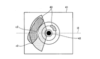
- FIG. 3 is a diagram illustrating a state in which the ROI is set below the ultrasonic image.
- the ROIr1 set in the ultrasonic image 41 shown in FIG. 3 is reduced or enlarged. .
- the ultrasonic endoscope 2 converts an electrical pulse signal received from the ultrasonic observation device 3 into an ultrasonic pulse (acoustic pulse) and irradiates the subject at the tip thereof, and is reflected by the subject. And an ultrasonic transducer 21 that converts the ultrasonic echo into an electrical echo signal (ultrasonic signal) that is expressed by a voltage change and outputs it.
- the ultrasonic transducer 21 is realized by a radial type transducer.
- the ultrasonic endoscope 2 may be one that mechanically scans the ultrasonic transducer 21, or a plurality of elements are provided in an array as the ultrasonic transducer 21, and the elements involved in transmission and reception are electronically arranged. Electronic scanning may be performed by switching or delaying transmission / reception of each element.
- the ultrasonic endoscope 2 is usually provided with an imaging unit having an imaging optical system and an imaging device, and is inserted into the digestive tract (esophagus, stomach, duodenum, large intestine) or respiratory organ (trachea, bronchi) of the subject.
- the gastrointestinal tract, respiratory tract and surrounding organs can be imaged.
- the ultrasonic endoscope 2 has a light guide that guides illumination light to be irradiated onto the subject during imaging.
- the light guide has a distal end portion that reaches the distal end of the insertion portion of the ultrasonic endoscope 2 into the subject, and a proximal end portion that is connected to a light source device that generates illumination light.
- the ultrasonic observation apparatus 3 includes a transmission / reception unit 31, a display control unit 32, an input unit 33, an operation control unit 34, a control unit 35, and a storage unit 36.
- the transmission / reception unit 31 transmits and receives electrical signals between the imaging unit and the ultrasonic transducer 21.
- the transmission / reception unit 31 is electrically connected to the imaging unit, transmits imaging information such as imaging timing to the imaging unit, and receives an imaging signal generated by the imaging unit.
- the transmission / reception unit 31 is electrically connected to the ultrasonic transducer 21 and transmits an electrical pulse signal to the ultrasonic transducer 21, and an echo signal that is an electrical reception signal from the ultrasonic transducer 21. Receive. Specifically, the transmission / reception unit 31 generates an electrical pulse signal based on a preset waveform and transmission timing, and transmits the generated pulse signal to the ultrasonic transducer 21.
- the transmission / reception unit 31 performs STC (Sensitivity Time Control) correction that amplifies an echo signal having a larger reception depth with a higher amplification factor.
- STC Signal to Transmission Control
- the transmission / reception unit 31 performs processing such as filtering on the amplified echo signal, and then performs A / D conversion to generate and output a time-domain digital high frequency (RF) signal.
- RF time-domain digital high frequency
- the display control unit 32 generates endoscopic image data based on the imaging signal and ultrasonic image data corresponding to the electrical echo signal. Further, the display control unit 32 superimposes and outputs various information on the endoscope image data and the ultrasound image data, and controls the display of the display device 4.
- the display control unit 32 is realized by using a CPU (Central Processing Unit) having arithmetic and control functions, various arithmetic circuits, and the like.
- CPU Central Processing Unit
- the input unit 33 receives the instruction signal input by the input device 5 and accepts input of various information according to the received instruction signal.
- Various types of information include observation mode setting and observation condition setting (for example, switching of gain and display range, scroll instruction information (slide direction and slide amount of B-mode image)), rotation instruction information (rotation of ultrasonic image 41). Direction and amount of rotation).
- the operation control unit 34 controls the shape of the ROI set in the ultrasonic image 41 according to a change in the contact position of a contact object such as an operator's finger that contacts the touch pad 51 of the input device 5.
- the control unit 35 is realized using a CPU having arithmetic and control functions, various arithmetic circuits, and the like.
- the operation control unit 34 includes a contact position detection unit 341 that detects a contact position of a contact object with respect to the touch pad 51, a contact angle calculation unit 342 that calculates a first positional relationship based on the two contact positions with respect to the touch pad 51, An ROI detection unit 343 that detects the position of the ROI set in the ultrasonic image 41, and an ROI angle calculation unit 344 that calculates a second positional relationship based on the position where the ROI is set and the reference position.
- the operation control unit 34 detects the correlation between the first positional relationship calculated by the contact angle calculation unit 342 and the second positional relationship calculated by the ROI angle calculation unit 344 and the contact position detection unit 341.
- the shape of the ROI is controlled based on the time change of the contact position.
- the contact position detection unit 341 detects the contact position of the contact object that the operator makes contact with the touch pad 51 of the input device 5 under the control of the control unit 35.
- FIG. 4 is a diagram illustrating a state where the operator performs a pinch-in operation in the vertical direction of the operation surface of the touch pad. As shown in FIG. 4, when the operator's hand h approaches the touch pad 51 of the input device 5 and the operator's finger touches two points on the operation surface of the touch pad 51, the contact position detection unit 341 The point p1 and the point p2, which are finger contact positions, are detected. Further, when the operator moves the contact position of the finger, the contact position detection unit 341 repeatedly detects the moved contact position every predetermined time.
- the contact angle calculation unit 342 calculates the first positional relationship under the control of the control unit 35.
- the first positional relationship is, for example, an angle (hereinafter referred to as a contact angle) between a first straight line passing through the center of two contact positions (point p1 and point p2) with respect to the touch pad 51 and a reference line.
- the reference line is, for example, a straight line corresponding to the horizontal side of the rectangular operation surface of the touch pad 51, but may be a straight line corresponding to the vertical side of the operation surface, and the method of setting the reference line is not particularly limited.
- FIG. 5 is a diagram for explaining the contact angle.
- the angle is the contact angle ⁇ .
- the angle between the straight line l1 and the straight line l2 is defined such that the contact angle ⁇ is in a range of 0 ° ⁇ ⁇ ⁇ 180 °, with the counterclockwise direction being positive with respect to the straight line l1. .
- the ROI detection unit 343 detects the position of the ROI set in the ultrasonic image 41 under the control of the control unit 35.
- the position of the ROI is, for example, the center of the ROI.
- the ultrasonic image 41 includes an ultrasonic transducer region 42 corresponding to the ultrasonic transducer 21 and an inspection target region 43 that is an inspection target such as a tumor.
- the ROIr1 is superimposed on the ultrasonic image 41.
- ROIr1 has a shape formed by removing a fan shape having a small diameter from a fan shape having a large diameter out of two fan shapes having a common central angle and different diameters with the central position of the ultrasonic transducer region 42 as the center.
- the center c1 of ROIr1 is a point located at the center in the radial direction and the center in the azimuth direction with respect to the center position of the ultrasonic transducer region 42 of ROIr1.
- the shape of the ROI is not particularly limited, and may be a trapezoid, a polygon, or the like arranged radially from the center position of the ultrasonic transducer region 42.
- the ROI angle calculation unit 344 calculates the second positional relationship under the control of the control unit 35.
- the second positional relationship is an angle between the second straight line passing through the center c1 of ROIr1 and the reference position and the reference line (hereinafter, ROI angle).
- the reference position is, for example, the center position of the ultrasonic transducer region 42.
- the reference line is a straight line corresponding to the straight line l1 in FIG.
- FIG. 6 is a diagram for explaining the ROI angle.
- a straight line l1 reference line
- the angle between the straight line l3 (second straight line) passing through the position is the ROI angle ⁇ .
- the angle between the straight line l1 and the straight line l3 is in the range of 0 ° ⁇ ⁇ ⁇ 180 °, with the counterclockwise direction being positive with respect to the straight line l1.
- An ROI angle ⁇ is defined.
- the operation control unit 34 When the correlation between the contact angle ⁇ and the ROI angle ⁇ satisfies a predetermined condition, the operation control unit 34 reduces or enlarges the shape of the ROIr1 in the direction along the reference axis, so that the contact angle ⁇ and the ROI angle ⁇ When the correlation does not satisfy a predetermined condition, the ROI shape is reduced or enlarged in a direction orthogonal to the reference axis.
- the reference axis is a straight line passing through the center c1 of ROIr1 and the center position of the ultrasonic transducer region 42, and is the straight line l3 in FIG.
- the predetermined condition is, for example, that the absolute value
- the control unit 35 controls the entire ultrasound diagnostic system 1.
- the control unit 35 is realized using a CPU having arithmetic and control functions, various arithmetic circuits, and the like.
- the control unit 35 reads out information stored and stored in the storage unit 36 from the storage unit 36 and performs various arithmetic processes related to the operation method of the ultrasonic observation device 3 to control the ultrasonic observation device 3 in an integrated manner. To do.
- the control unit 35 may be configured using a CPU or the like common to the display control unit 32 and the operation control unit 34.
- the storage unit 36 stores various programs for operating the ultrasonic diagnostic system 1, data including various parameters necessary for the operation of the ultrasonic diagnostic system 1, and the like.
- the storage unit 36 stores, for example, the initial position (sound ray number) of the writing position of the ultrasonic image 41 (ultrasonic transmission start position).
- the storage unit 36 stores various programs including an operation program for executing the operation method of the ultrasonic diagnostic system 1.
- the operation program can be stored in a computer-readable storage medium such as a hard disk, a flash memory, a CD-ROM, a DVD-ROM, or a flexible disk and widely distributed.
- the various programs described above can also be obtained by downloading via a communication network.
- the communication network here is realized by, for example, an existing public line network, a LAN (Local Area Network), a WAN (Wide Area Network) or the like, and may be wired or wireless.
- the storage unit 36 having the above configuration is realized using a ROM (Read Only Memory) in which various programs are installed in advance, and a RAM (Random Access Memory) that stores calculation parameters and data of each process. .
- ROM Read Only Memory
- RAM Random Access Memory
- the display device 4 is connected to the ultrasonic observation device 3.
- the display device 4 is configured using a display panel made of liquid crystal, organic EL (Electro Luminescence), or the like.
- the display device 4 displays, for example, an ultrasonic image 41 output from the ultrasonic observation device 3 and various information related to the operation.
- the input device 5 has a main body as a casing, and the outer surface of the main body is covered with a cover made of silicone or the like in a watertight manner.
- the input device 5 includes a touch pad 51 that detects contact of a contact object such as an operator's finger, and a display unit 52 that can display various types of information.
- the operation surface of the touch pad 51 is square or rectangular.
- the input device 5 is electrically connected to the ultrasonic observation device 3 via a cable, and outputs an instruction input signal or the like to the touch pad 51 to the input unit 33.
- the input device 5 detects a contact position by a contact sensor and outputs it to the ultrasonic observation device 3 when a contact object such as an operator's finger contacts the touch pad 51. Further, when the contact object moves while being in contact with the touch pad 51, the movement direction and the movement amount are detected and output to the ultrasonic observation apparatus 3.
- the ultrasonic observation apparatus 3 performs signal processing according to the input contact position, the movement direction and the movement amount of the contact position based on the received information. And the ultrasonic observation apparatus 3 outputs the image which made the position of the image displayed on the display apparatus 4 slide or rotate based on the received information, for example.
- Display unit 52 displays observation mode settings, observation condition settings, and the like.
- the display unit 52 includes a touch panel and may be configured to change observation mode settings, observation condition settings, and the like.
- FIG. 7 is a flowchart showing the operation of the ultrasonic observation apparatus according to Embodiment 1 of the present invention.
- the control unit 35 determines whether or not there is an operation input (step S1). Specifically, the control unit 35 determines whether an operation input performed by the operator on the touch pad 51 of the input device 5 is input via the input unit 33.
- control unit 35 determines whether or not there are two contact positions (step S2). Specifically, the control unit 35 acquires an operation input performed by the operator on the touch pad 51 of the input device 5 through the input unit 33, causes the contact position detection unit 341 to detect the contact position, It is determined whether the contact positions detected by the contact position detection unit 341 are two points.
- step S3 the control unit 35 determines whether the contact position has moved. Specifically, the control unit 35 determines whether or not the contact position detected by the contact position detection unit 341 has moved.
- control unit 35 determines whether the operation on the touch pad 51 is a pinch-in operation or a pinch-out operation (step S4). Specifically, the control unit 35 determines whether or not the two contact positions detected by the contact position detection unit 341 have moved in directions toward or away from each other.
- control unit 35 determines that the operation on the touch pad 51 is a pinch-in operation or a pinch-out operation (step S4: Yes)
- the control unit 35 causes the contact angle calculation unit 342 to calculate the contact angle ⁇ (step S5).
- the control unit 35 causes the ROI detection unit 343 to detect the position of the ROI (step S6), and causes the ROI angle calculation unit 344 to calculate the ROI angle ⁇ (step S7).
- control unit 35 determines that the correlation (
- control unit 35 determines that the correlation (
- the control unit 35 causes the operation control unit 34 to reduce or enlarge the ROI shape in the direction along the reference axis (step S9).
- FIG. 8 is a diagram illustrating a state in which the shape of the ROI is reduced in the direction along the reference axis when the ROI is below the ultrasonic image.
- the control unit 35 causes the operation control unit 34 to reduce the shape of ROIr1 in the direction along the reference axis (the straight line l3 in FIG. 8) to obtain ROIr2.
- FIG. 9 is a diagram illustrating a state in which the ROI is set on the left side of the ultrasonic image.
- a straight line l3 passing through the center c2 of ROIr3 and the center position of the ultrasonic transducer region 42 is a straight line extending in the left-right direction in FIG. 9, so the ROI angle ⁇ is approximately 0 °.
- FIG. 10 is a diagram illustrating a state where the operator performs a pinch-in operation in the left-right direction of the operation surface of the touch pad.
- the straight line l4 passing through the centers of the two contact positions (points p3 and p4) with respect to the touch pad 51 is a straight line extending in the left-right direction in FIG. 10, the contact angle ⁇ is approximately 0 °.
- FIG. 11 is a diagram illustrating a state in which the shape of the ROI is reduced in the direction along the reference axis when the ROI is on the left side of the ultrasonic image.
- the control unit 35 causes the operation control unit 34 to reduce the shape of ROIr3 in the direction along the reference axis (the straight line l3 in FIG. 11) to obtain ROIr4.
- control unit 35 determines whether or not there is an end instruction input (step S10).
- step S10: Yes a series of processing is performed. finish.
- step S10: No the process returns to step S1 and the processing is continued.
- Step S8 when the control unit 35 determines that the correlation (
- FIG. 12 is a diagram illustrating how the ROI shape is reduced in a direction orthogonal to the reference axis when the ROI is below the ultrasonic image.
- the control unit 35 causes the operation control unit 34 to reduce the shape of ROIr2 in the direction orthogonal to the reference axis (straight line 13 in FIG. 12), thereby obtaining ROIr5.
- FIG. 13 is a diagram illustrating a state in which the shape of the ROI is reduced in a direction orthogonal to the reference axis when the ROI is on the left side of the ultrasonic image.
- the control unit 35 causes the operation control unit 34 to reduce the shape of ROIr4 in the direction orthogonal to the reference axis (straight line 13 in FIG. 13) to obtain ROIr6.
- step S10 Thereafter, the end determination of step S10 is performed, and the processing is ended or continued.
- step S2 when the control unit 35 determines that the contact position is not two points (step S2: No), that is, when the contact position is one point, for example, the control unit 35 responds to an operation input. Then, the operation control unit 34 is caused to perform the ROI setting operation for changing the position where the ROI is set. Note that when there are three or more contact positions, it may be handled that there is no operation input.
- step S4 when the control unit 35 determines that the operation on the touch pad 51 is not a pinch-in operation or a pinch-out operation (step S4: No), the control unit 35 determines that the operation on the touch pad 51 is a scroll operation ( When the two contact positions move in the same direction), the operation control unit 34 is caused to perform a scroll operation for scrolling the center position of the ultrasonic image 41, and the operation on the touch pad 51 is a rotation operation (the two contact positions are The operation control unit 34 is caused to perform a rotation operation for rotating the ultrasonic image 41 around the center position of the ultrasonic transducer region 42.
- step S1 if the operation has not been performed for a predetermined time or more (step S1: No), and the step of determining whether or not the contact position has moved (step In S3), when there is no movement of the contact position for a predetermined time or more (step S3: No), the end determination of step S10 is performed, and the series of processes is ended or continued.
- the direction of the operator's pinch-in operation or pinch-out operation substantially coincides with the direction in which the ROI is reduced or enlarged in the ultrasonic image 41. Intuitive operation when reducing or enlarging.
- FIG. 14 is a diagram for explaining the operation of the ultrasonic observation apparatus according to Modification 1-1 of Embodiment 1 of the present invention.
- the direction of the pinch-in operation is a direction along the straight line l21, and the pinch-in operation satisfying 0 ° ⁇
- the amount of reduction of the ROI may be multiplied by a coefficient cos (
- the direction of the pinch-in operation is a direction along the straight line 122 and a pinch-in operation that does not satisfy 0 ° ⁇
- the amount of movement of the finger in the pinch-in operation may be multiplied by sin (
- the amount of deformation of the ROI changes according to the direction of the pinch-in operation, so that the operator can perform a more intuitive operation.
- Embodiment 2 Next, an ultrasonic diagnostic system according to Embodiment 2 will be described.
- the configuration of the ultrasonic diagnostic system may be the same as that of the ultrasonic diagnostic system 1 according to Embodiment 1 shown in FIG.
- the operation control unit 34 reduces the ROI shape in both the direction along the reference axis and the direction orthogonal to the reference axis based on the correlation (
- FIG. 15 is a flowchart showing the operation of the ultrasonic observation apparatus according to the second embodiment of the present invention.
- the control unit 35 determines the shape of the ROI in the operation control unit 34 based on the correlation (
- FIG. 16 is a diagram for explaining the operation of the ultrasonic observation apparatus according to the second embodiment of the present invention.
- the direction of the pinch-in operation is a direction along the straight line l23
- the ROI is reduced along the direction of the reference axis (the straight line l3 in FIG. 16) with respect to the movement amount of the finger in the pinch-in operation.
- ) may be multiplied as a coefficient to be multiplied
- ) may be multiplied as a coefficient for reducing the ROI in a direction orthogonal to the reference axis (straight line 11 in FIG. 16).
- FIG. 17 is a diagram illustrating a state in which the ROI shape is reduced in a direction along the reference axis and in a direction perpendicular to the reference axis when the ROI is below the ultrasonic image.
- the pinch-in operation shown in FIG. 16 is performed when ROIr1 is below the ultrasonic image 41 (6 o'clock direction).
- the control unit 35 causes the operation control unit 34 to move in the direction of the reference axis (the straight line 13 in FIG. 17) with respect to the movement amount of the finger for pinch-in operation.
- the control unit 35 causes the operation control unit 34 to reduce or enlarge the shape of the ROI along the direction in which the pinch-in operation is performed based on the correlation (
- the operator can perform a more intuitive operation.
- Embodiment 3 Next, an ultrasonic diagnostic system according to Embodiment 3 will be described.
- the configuration of the ultrasonic diagnostic system may be the same as that of the ultrasonic diagnostic system 1 according to Embodiment 1 shown in FIG.
- the operation control unit 34 has a correlation (
- ⁇ 180 ° (first condition) the ROI shape is reduced or expanded in the direction along the reference axis, and the correlation (
- ⁇ 105 ° (second condition) the ROI shape is reduced or enlarged in a direction perpendicular to the reference axis.
- the operation control unit 34 has a correlation (
- the angle does not satisfy 165 ° or 165 ° ⁇
- FIG. 18 is a flowchart showing the operation of the ultrasonic observation apparatus according to the third embodiment of the present invention.
- the control unit 35 determines that the correlation (
- control unit 35 determines that the correlation (
- the control unit 35 causes the operation control unit 34 to reduce or enlarge the ROI shape in the direction along the reference axis (step S9).
- step S31 determines whether or not the correlation (
- step S32 When the control unit 35 determines that the correlation (
- the ROI shape is reduced or enlarged in a direction perpendicular to the reference axis (step S11).
- control unit 35 determines that the correlation (
- the control unit 35 performs the operation control.
- the unit 34 reduces or enlarges the ROI shape in the direction along the reference axis and in the direction orthogonal to the reference axis (step S21).
- the ROI can be easily reduced or expanded in the direction along the reference axis and in the direction orthogonal to the reference axis, and the shape of the ROI can be determined according to the direction of the pinch-in operation. Since it can be deformed, operability is good.
Abstract
超音波観測装置は、観測対象へ超音波を送信し、該観測対象で反射された超音波を受信する超音波振動子から受信した超音波信号に基づいて生成される超音波画像を表示装置に表示させる超音波観測装置であって、入力装置が有するタッチパッドに接触する接触物の接触位置の変化に応じて、超音波画像内に設定された関心領域の形状を制御する操作制御部を備え、操作制御部は、タッチパッドに対する接触物の接触位置を検出し、タッチパッドに対する2つの接触位置に基づく第1の位置関係を算出し、超音波画像内に設定された関心領域の位置を検出し、関心領域が設定されている位置と基準位置とに基づく第2の位置関係を算出し、第1の位置関係と第2の位置関係との相関関係に基づいて、関心領域の形状を制御する。これにより、関心領域を縮小又は拡大する際に直感的に操作することができる超音波観測装置を提供する。
Description
本発明は、超音波観測装置、超音波観測装置の作動方法、及び超音波観測装置の作動プログラムに関する。
従来、超音波を用いて観察対象を診断する技術として、超音波エラストグラフィが知られている。超音波エラストグラフィは、生体内の癌や腫瘍組織の硬さが病気の進行状況や生体によって異なることを利用する技術である。この技術では、設定された関心領域(ROI:Region of Interest)における生体組織の変位量の平均値を基準値として色付けを行うことにより、生体組織の硬さに関する情報を画像化した弾性画像を生成する。超音波エラストグラフィでは、操作者が観察内容に応じて関心領域を設定する。
ところで、従来、超音波内視鏡の操作には、トラックボールが用いられていたが、近年では、洗浄性の観点から、タッチパッドが用いられている。特許文献1には、タッチパッドに対するピンチイン操作又はピンチアウト操作により、選択する領域を縮小又は拡大する技術が開示されている。
ROIが超音波画像の中心から放射状の領域に配置されている場合、ROIの方位角方向(幅方向)又はROIの径方向(深度方向)への縮小又は拡大を、タッチパッドに対する操作方向と対応させると、超音波画像におけるROIの位置によっては、操作方向と超音波画像におけるROIの縮小又は拡大方向とが一致しなくなる場合がある。例えば、ROIの方位角方向の縮小又は拡大をタッチパッドの左右方向のピンチイン操作又はピンチアウト操作に対応させ、ROIの径方向の縮小又は拡大をタッチパッドの上下方向のピンチイン操作又はピンチアウト操作に対応させたとする。このとき、ROIが超音波画像の下方(6時方向)にある場合に、タッチパッドに左右方向のピンチイン操作を行うとROIが方位角方向(超音波画像における左右方向)に縮小され、操作方向と超音波画像におけるROIの縮小方向とが略一致するのに対し、ROIが超音波画像の左側(9時方向)にある場合に、タッチパッドに左右方向のピンチイン操作を行うとROIが方位角方向(超音波画像における上下方向)に縮小され、操作方向と超音波画像におけるROIの縮小方向とが一致しない。その結果、ROIが超音波画像の左側にある場合に、操作者が超音波画像におけるROIを左右方向に縮小しようとして、直感的にタッチパッドに対して左右方向のピンチイン操作を行うと、操作者の意図する縮小方向と超音波画像におけるROIの縮小方向とが一致せず、直感的な操作を行うことができないという課題があった。
本発明は、上記に鑑みてなされたものであって、関心領域を縮小又は拡大する際に直感的に操作することができる超音波観測装置、超音波観測装置の作動方法、及び超音波観測装置の作動プログラムを提供することを目的とする。
上述した課題を解決し、目的を達成するために、本発明の一態様に係る超音波観測装置は、観測対象へ超音波を送信し、該観測対象で反射された超音波を受信する超音波振動子から受信した超音波信号に基づいて生成される超音波画像を表示装置に表示させる超音波観測装置であって、入力装置が有するタッチパッドに接触する接触物の接触位置の変化に応じて、前記超音波画像内に設定された関心領域の形状を制御する操作制御部を備え、前記操作制御部は、前記タッチパッドに対する前記接触物の前記接触位置を検出し、前記タッチパッドに対する2つの前記接触位置に基づく第1の位置関係を算出し、前記超音波画像内に設定された前記関心領域の位置を検出し、前記関心領域が設定されている位置と基準位置とに基づく第2の位置関係を算出し、前記第1の位置関係と前記第2の位置関係との相関関係に基づいて、前記関心領域の形状を制御することを特徴とする。
また、本発明の一態様に係る超音波観測装置は、前記操作制御部は、前記相関関係が所定の条件を満たす場合、前記関心領域の形状を基準軸に沿った方向に縮小又は拡大し、前記相関関係が前記所定の条件を満たさない場合、前記関心領域の形状を前記基準軸と直交する方向に縮小又は拡大することを特徴とする。
また、本発明の一態様に係る超音波観測装置は、前記操作制御部は、前記相関関係に基づいて、前記関心領域の形状を基準軸に沿った方向、及び前記基準軸と直交する方向に縮小又は拡大することを特徴とする。
また、本発明の一態様に係る超音波観測装置は、前記操作制御部は、前記相関関係が第1の条件を満たす場合、前記関心領域の形状を基準軸に沿った方向に縮小又は拡大し、前記相関関係が第2の条件を満たす場合、前記関心領域の形状を前記基準軸と直交する方向に縮小又は拡大し、前記相関関係が前記第1の条件及び前記第2の条件を満たさない場合、前記相関関係に基づいて、前記関心領域の形状を前記基準軸に沿った方向、及び前記基準軸と直交する方向に縮小又は拡大することを特徴とする。
また、本発明の一態様に係る超音波観測装置は、前記第1の位置関係は、前記タッチパッドに対する2つの前記接触位置の中心を通る第1の直線と基準線との間の角度であることを特徴とする。
また、本発明の一態様に係る超音波観測装置は、前記第2の位置関係は、前記関心領域の中心と前記基準位置とを通る第2の直線と基準線との間の角度であることを特徴とする。
また、本発明の一態様に係る超音波観測装置は、前記タッチパッドの操作面は正方形又は長方形をなし、前記基準線は、前記タッチパッドの操作面の縦辺又は横辺に対応する直線であることを特徴とする。
また、本発明の一態様に係る超音波観測装置は、前記基準位置は、前記表示装置に表示された前記超音波画像内の前記超音波振動子に対応する超音波振動子領域の中心位置であることを特徴とする。
また、本発明の一態様に係る超音波観測装置は、前記関心領域は、前記表示装置に表示された前記超音波画像内の前記超音波振動子に対応する超音波振動子領域の中心位置を中心として、中心角が共通である径が異なる2つの扇形のうち、径が大きい前記扇形から径が小さい前記扇形を取り除いてできる形状をなすことを特徴とする。
また、本発明の一態様に係る超音波観測装置は、前記関心領域の中心は、前記関心領域の前記超音波振動子領域の前記中心位置に対する径方向の中心かつ方位角方向の中心にある点であることを特徴とする。
また、本発明の一態様に係る超音波観測装置の作動方法は、観測対象へ超音波を送信し、該観測対象で反射された超音波を受信する超音波振動子から受信した超音波信号に基づいて生成される超音波画像を表示装置に表示させる超音波観測装置の作動方法であって、操作制御部が、入力装置が有するタッチパッドに接触する接触物の接触位置を検出する接触位置検出ステップと、前記操作制御部が、前記タッチパッドに対する2つの前記接触位置に基づく第1の位置関係を算出する第1の位置関係算出ステップと、前記操作制御部が、前記超音波画像内に設定された関心領域の位置を検出する関心領域検出ステップと、前記操作制御部が、前記関心領域が設定されている位置と基準位置とに基づく第2の位置関係を算出する第2の位置関係算出ステップと、前記操作制御部が、前記第1の位置関係と前記第2の位置関係との相関関係に基づいて、前記超音波画像内に設定された前記関心領域の形状を制御する形状制御ステップと、を含むことを特徴とする。
また、本発明の一態様に係る超音波観測装置の作動プログラムは、観測対象へ超音波を送信し、該観測対象で反射された超音波を受信する超音波振動子から受信した超音波信号に基づいて生成される超音波画像を表示装置に表示させる超音波観測装置の作動プログラムであって、操作制御部が、入力装置が有するタッチパッドに接触する接触物の接触位置を検出する接触位置検出ステップと、前記操作制御部が、前記タッチパッドに対する2つの接触位置に基づく第1の位置関係を算出する第1の位置関係算出ステップと、前記操作制御部が、前記超音波画像内に設定された関心領域の位置を検出する関心領域検出ステップと、前記操作制御部が、前記関心領域が設定されている位置と基準位置とに基づく第2の位置関係を算出する第2の位置関係算出ステップと、前記操作制御部が、前記第1の位置関係と前記第2の位置関係との相関関係に基づいて、前記超音波画像内に設定された前記関心領域の形状を制御する形状制御ステップと、を超音波観測装置に実行させることを特徴とする。
本発明によれば、関心領域を縮小又は拡大する際に直感的に操作することができる超音波観測装置、超音波観測装置の作動方法、及び超音波観測装置の作動プログラムを実現することができる。
以下に、図面を参照して本発明に係る超音波観測装置、超音波観測装置の作動方法、及び超音波観測装置の作動プログラムの実施の形態を説明する。なお、これらの実施の形態により本発明が限定されるものではない。以下の実施の形態においては、超音波内視鏡を備える超音波診断システムを例示して説明するが、本発明は、体外式の超音波診断システムや工業用の超音波診断システム等、超音波診断システム一般に適用することができる。
また、図面の記載において、同一又は対応する要素には適宜同一の符号を付している。また、図面は模式的なものであり、各要素の寸法の関係、各要素の比率などは、現実と異なる場合があることに留意する必要がある。図面の相互間においても、互いの寸法の関係や比率が異なる部分が含まれている場合がある。
(実施の形態1)
図1は、本発明の実施の形態1に係る超音波観測装置を備えた超音波診断システムの構成を示すブロック図である。図1に示すように、超音波診断システム1は、観測対象である被検体へ超音波を送信し、該被検体で反射された超音波を受信する超音波内視鏡2と、超音波内視鏡2が取得した超音波信号に基づいて超音波画像を生成する超音波観測装置3と、超音波観測装置3が生成した超音波画像を表示する表示装置4と、超音波観測装置3に観察モードの設定や観測条件の設定等の指示信号の入力を受け付ける入力装置5と、を備える。
図1は、本発明の実施の形態1に係る超音波観測装置を備えた超音波診断システムの構成を示すブロック図である。図1に示すように、超音波診断システム1は、観測対象である被検体へ超音波を送信し、該被検体で反射された超音波を受信する超音波内視鏡2と、超音波内視鏡2が取得した超音波信号に基づいて超音波画像を生成する超音波観測装置3と、超音波観測装置3が生成した超音波画像を表示する表示装置4と、超音波観測装置3に観察モードの設定や観測条件の設定等の指示信号の入力を受け付ける入力装置5と、を備える。
図2は、図1に示す入力装置の構成を示す図である。図3は、超音波画像の下方にROIが設定されている様子を表す図である。超音波診断システム1では、操作者が図2に示す入力装置5のタッチパッド51に対して操作を行うことにより、図3に示す超音波画像41内に設定されたROIr1が縮小又は拡大される。
超音波内視鏡2は、その先端部に、超音波観測装置3から受信した電気的なパルス信号を超音波パルス(音響パルス)に変換して被検体へ照射するとともに、被検体で反射された超音波エコーを電圧変化で表現する電気的なエコー信号(超音波信号)に変換して出力する超音波振動子21を有する。超音波振動子21は、ラジアル型の振動子により実現される。超音波内視鏡2は、超音波振動子21をメカ的に走査させるものであってもよいし、超音波振動子21として複数の素子をアレイ状に設け、送受信にかかわる素子を電子的に切り替えたり、各素子の送受信に遅延をかけたりすることで、電子的に走査させるものであってもよい。
超音波内視鏡2は、通常は撮像光学系及び撮像素子を有する撮像部を備えており、被検体の消化管(食道、胃、十二指腸、大腸)、又は呼吸器(気管、気管支)へ挿入され、消化管、呼吸器やその周囲臓器(膵臓、胆嚢、胆管、胆道、リンパ節、縦隔臓器、血管等)を撮像することが可能である。また、超音波内視鏡2は、撮像時に被検体へ照射する照明光を導くライトガイドを有する。このライトガイドは、先端部が超音波内視鏡2の被検体への挿入部の先端まで達している一方、基端部が照明光を発生する光源装置に接続されている。
超音波観測装置3は、送受信部31と、表示制御部32と、入力部33と、操作制御部34と、制御部35と、記憶部36と、を備える。
送受信部31は、撮像部及び超音波振動子21との間で電気信号の送受信を行う。送受信部31は、撮像部と電気的に接続され、撮像タイミング等の撮像情報を撮像部に送信するとともに、撮像部が生成した撮像信号を受信する。また、送受信部31は、超音波振動子21と電気的に接続され、電気的なパルス信号を超音波振動子21へ送信するとともに、超音波振動子21から電気的な受信信号であるエコー信号を受信する。具体的には、送受信部31は、予め設定された波形及び送信タイミングに基づいて電気的なパルス信号を生成し、この生成したパルス信号を超音波振動子21へ送信する。
送受信部31は、受信深度が大きいエコー信号ほど高い増幅率で増幅するSTC(Sensitivity Time Control)補正等を行う。送受信部31は、増幅されたエコー信号に対してフィルタリング等の処理を施した後、A/D変換することによって時間ドメインのデジタル高周波(RF:Radio Frequency)信号を生成して出力する。
表示制御部32は、撮像信号に基づく内視鏡画像データ、及び電気的なエコー信号に対応する超音波画像データの生成を行う。さらに、表示制御部32は、内視鏡画像データ及び超音波画像データに種々の情報を重畳して出力し、表示装置4の表示を制御する。表示制御部32は、演算及び制御機能を有するCPU(Central Processing Unit)や各種演算回路等を用いて実現される。
入力部33は、入力装置5によって入力された指示信号を受信して、該受信した指示信号に応じた各種情報の入力を受け付ける。各種情報としては、観察モードの設定や観測条件の設定(例えば、ゲイン及び表示レンジの切り替え、スクロール指示情報(Bモード画像のスライド方向及びスライド量))、回転指示情報(超音波画像41の回転方向及び回転量)等が挙げられる。
操作制御部34は、入力装置5が有するタッチパッド51に接触する例えば操作者の指等の接触物の接触位置の変化に応じて、超音波画像41内に設定されたROIの形状を制御する。制御部35は、演算及び制御機能を有するCPUや各種演算回路等を用いて実現される。
操作制御部34は、タッチパッド51に対する接触物の接触位置を検出する接触位置検出部341と、タッチパッド51に対する2つの接触位置に基づく第1の位置関係を算出する接触角度算出部342と、超音波画像41内に設定されたROIの位置を検出するROI検出部343と、ROIが設定されている位置と基準位置とに基づく第2の位置関係を算出するROI角度算出部344と、を備える。そして、操作制御部34は、接触角度算出部342により算出された第1の位置関係とROI角度算出部344により算出された第2の位置関係との相関関係と接触位置検出部341が検出した接触位置の時間変化とに基づいて、ROIの形状を制御する。
接触位置検出部341は、制御部35の制御のもと、入力装置5のタッチパッド51に操作者が接触させた接触物の接触位置を検出する。図4は、操作者がタッチパッドの操作面の上下方向にピンチイン操作を行う様子を表す図である。図4に示すように、入力装置5のタッチパッド51に操作者の手hが近づき、タッチパッド51の操作面上の2点に操作者の指が接触した場合、接触位置検出部341は、指の接触位置である点p1及び点p2を検出する。さらに、操作者が指の接触位置を移動させると、接触位置検出部341は、移動した接触位置を所定時間毎に繰り返し検出する。
接触角度算出部342は、制御部35の制御のもと、第1の位置関係を算出する。第1の位置関係は、例えばタッチパッド51に対する2つの接触位置(点p1及び点p2)の中心を通る第1の直線と基準線との間の角度(以下、接触角度)である。基準線は、例えばタッチパッド51の長方形の操作面の横辺に対応する直線であるが、操作面の縦辺に対応する直線であってもよく、基準線の設定の仕方は特に限定されない。
図5は、接触角度を説明するための図である。図5に示すように、タッチパッド51の長方形の操作面の横辺に対応する直線l1(基準線)と、点p1及び点p2の中心を通る直線l2(第1の直線)との間の角度が接触角度αである。なお、本明細書において、直線l1と直線l2との間の角度は、直線l1に対して反時計回りの方向を正として、0°≦α<180°の範囲で接触角度αが定義される。
ROI検出部343は、制御部35の制御のもと、超音波画像41内に設定されているROIの位置を検出する。ROIの位置は、例えばROIの中心である。図3に示すように、超音波画像41内には、超音波振動子21に対応する超音波振動子領域42と、例えば腫瘍等の検査対象である検査対象領域43と、が含まれており、超音波画像41上にROIr1が重畳されている。ROIr1は、超音波振動子領域42の中心位置を中心として、中心角が共通である径が異なる2つ扇形のうち、径が大きい扇形から径が小さい扇形を取り除いてできる形状をなす。ROIr1の中心c1は、ROIr1の超音波振動子領域42の中心位置に対する径方向の中心かつ方位角方向の中心にある点である。なお、ROIの形状は特に限定されず、超音波振動子領域42の中心位置から放射状に配置された台形や多角形等であってもよい。
ROI角度算出部344は、制御部35の制御のもと、第2の位置関係を算出する。第2の位置関係は、ROIr1の中心c1と基準位置とを通る第2の直線と基準線との間の角度(以下、ROI角度)である。基準位置は、例えば超音波振動子領域42の中心位置である。基準線は、図5の直線l1に対応する直線である。
図6は、ROI角度を説明するための図である。図6に示すように、超音波画像41においてタッチパッド51の操作面の横辺に対応する水平方向に延伸する直線l1(基準線)と、ROIr1の中心c1と超音波振動子領域42の中心位置とを通る直線l3(第2の直線)との間の角度がROI角度βである。なお、本明細書において、接触角度αと同様に、直線l1と直線l3との間の角度は、直線l1に対して反時計回りの方向を正として、0°≦β<180°の範囲でROI角度βが定義される。
操作制御部34は、接触角度αとROI角度βとの相関関係が所定の条件を満たす場合、ROIr1の形状を基準軸に沿った方向に縮小又は拡大し、接触角度αとROI角度βとの相関関係が所定の条件を満たさない場合、ROIの形状を基準軸と直交する方向に縮小又は拡大する。基準軸は、ROIr1の中心c1と超音波振動子領域42の中心位置とを通る直線であり、図6の直線l3である。所定の条件は、例えば接触角度αとROI角度βとの相関関係であるα-βの絶対値|α-β|が、0°≦|α-β|≦45°又は135°≦|α-β|<180°を満たすことである。
制御部35は、超音波診断システム1全体を制御する。制御部35は、演算及び制御機能を有するCPUや各種演算回路等を用いて実現される。制御部35は、記憶部36が記憶、格納する情報を記憶部36から読み出し、超音波観測装置3の作動方法に関連した各種演算処理を実行することによって超音波観測装置3を統括して制御する。なお、制御部35を表示制御部32や操作制御部34と共通のCPU等を用いて構成することも可能である。
記憶部36は、超音波診断システム1を動作させるための各種プログラム、及び超音波診断システム1の動作に必要な各種パラメータ等を含むデータ等を記憶する。記憶部36は、例えば、超音波画像41の書出し位置(超音波の送信開始位置)の初期位置(音線番号)を記憶している。
また、記憶部36は、超音波診断システム1の作動方法を実行するための作動プログラムを含む各種プログラムを記憶する。作動プログラムは、ハードディスク、フラッシュメモリ、CD-ROM、DVD-ROM、フレキシブルディスク等のコンピュータ読み取り可能な記憶媒体に記憶して広く流通させることも可能である。なお、上述した各種プログラムは、通信ネットワークを介してダウンロードすることによって取得することも可能である。ここでいう通信ネットワークは、例えば既存の公衆回線網、LAN(Local Area Network)、WAN(Wide Area Network)等によって実現されるものであり、有線、無線を問わない。
以上の構成を有する記憶部36は、各種プログラム等が予めインストールされたROM(Read Only Memory)、及び各処理の演算パラメータやデータ等を記憶するRAM(Random Access Memory)等を用いて実現される。
表示装置4は、超音波観測装置3に接続されている。表示装置4は、液晶又は有機EL(Electro Luminescence)等からなる表示パネルを用いて構成される。表示装置4は、例えば、超音波観測装置3が出力する超音波画像41や、操作にかかる各種情報を表示する。
入力装置5は、図2に示すように、本体が筐体であり、本体の外表面がシリコーン等からなるカバーで水密に覆われている。入力装置5は、操作者の指等の接触物の接触を検知するタッチパッド51と、各種情報を表示可能な表示部52と、を有する。タッチパッド51の操作面は、正方形又は長方形をなす。入力装置5は、ケーブルを介して超音波観測装置3に電気的に接続され、タッチパッド51に対する指示入力の信号等を入力部33に出力する。
入力装置5は、タッチパッド51に操作者の指等の接触物が接触すると、接触センサにより接触位置を検知して超音波観測装置3に出力する。また、接触物がタッチパッド51に接触したまま移動すると、その移動方向や移動量を検知して超音波観測装置3に出力する。超音波観測装置3は、受信した情報をもとに、入力された接触位置、接触位置の移動方向及び移動量に応じた信号処理を行なう。そして、超音波観測装置3は、例えば受信した情報に基づいて、表示装置4に表示させる画像の位置をスライド又は回転等させた画像を出力する。
表示部52は、観察モードの設定や観測条件の設定等を表示する。表示部52は、タッチパネルからなり、観察モードの設定や観測条件の設定等を変更することができる構成であってもよい。
次に、表示装置4に表示された超音波画像41内のROIr1を縮小又は拡大する操作について詳細に説明する。図7は、本発明の実施の形態1に係る超音波観測装置の動作を示すフローチャートである。図7に示すように、はじめに、制御部35は、操作入力があったか否かを判定する(ステップS1)。具体的には、制御部35は、操作者が入力装置5のタッチパッド51に対して行った操作入力が、入力部33を介して入力されたか否かを判定する。
制御部35が、操作入力があったと判定した場合(ステップS1:Yes)、制御部35は、接触位置が2点であるか否かを判定する(ステップS2)。具体的には、制御部35は、操作者が入力装置5のタッチパッド51に対して行った操作入力を、入力部33を介して取得し、接触位置検出部341に接触位置を検出させ、接触位置検出部341が検出した接触位置が2点であるか否かを判定する。
制御部35が、接触位置が2点であると判定した場合(ステップS2:Yes)、制御部35は、接触位置が動いたか否かを判定する(ステップS3)。具体的には、制御部35は、接触位置検出部341が検出した接触位置が動いたか否かを判定する。
制御部35が、接触位置が動いたと判定した場合(ステップS3:Yes)、制御部35は、タッチパッド51に対する操作がピンチイン操作又はピンチアウト操作であるか否かを判定する(ステップS4)。具体的には、制御部35は、接触位置検出部341が検出した2点の接触位置が近づく又は離れる方向に移動したか否かを判定する。
制御部35が、タッチパッド51に対する操作がピンチイン操作又はピンチアウト操作であると判定した場合(ステップS4:Yes)、制御部35は、接触角度算出部342に接触角度αを算出させる(ステップS5)。さらに、制御部35は、ROI検出部343にROIの位置を検出させ(ステップS6)、ROI角度算出部344にROI角度βを算出させる(ステップS7)。
その後、制御部35は、接触角度αとROI角度βとの相関関係(|α-β|)が、0°≦|α-β|≦45°又は135°≦|α-β|<180°を満たす範囲にあるか否かを判定する(ステップS8)。
制御部35が、相関関係(|α-β|)が、0°≦|α-β|≦45°又は135°≦|α-β|<180°を満たすと判定した場合(ステップS8:Yes)、制御部35は、操作制御部34にROIの形状を基準軸に沿った方向に縮小又は拡大させる(ステップS9)。
まず、ROIが超音波画像41の下方(6時方向)にある場合に、0°≦|α-β|≦45°又は135°≦|α-β|<180°を満たすピンチイン操作が行われた場合について説明する。図3に示すROIr1が超音波画像41の下方(6時方向)にある場合に、図4に示すタッチパッド51の操作面に対する上下方向のピンチイン操作が行われたとする。このとき、図5及び図6に示すように、接触角度αとROI角度βとは、略90°であり、|α-β|は略0°である。従って、0°≦|α-β|≦45°又は135°≦|α-β|<180°が満たされており、ROIr1の形状が基準軸に沿った方向に縮小される。
図8は、ROIが超音波画像の下方にある場合に、ROIの形状が基準軸に沿った方向に縮小される様子を表す図である。図8に示すように、制御部35は、操作制御部34にROIr1の形状を基準軸(図8の直線l3)に沿った方向に縮小させ、ROIr2にする。
続いて、ROIが超音波画像41の左側(9時方向)にある場合に、0°≦|α-β|≦45°又は135°≦|α-β|<180°を満たすピンチイン操作が行われた場合について説明する。図9は、超音波画像の左側にROIが設定されている様子を表す図である。図9において、ROIr3の中心c2と超音波振動子領域42の中心位置とを通る直線l3は、図9の左右方向に延伸する直線であるから、ROI角度βは略0°である。図10は、操作者がタッチパッドの操作面の左右方向にピンチイン操作を行う様子を表す図である。図10において、タッチパッド51に対する2つの接触位置(点p3及び点p4)の中心を通る直線l4は、図10の左右方向に延伸する直線であるから、接触角度αは略0°である。
図9に示すROIr3が超音波画像41の左側(9時方向)にある場合に、図10に示すタッチパッド51の操作面に対する左右方向のピンチイン操作が行われたとする。このとき、接触角度αとROI角度βとは、略0°であり、|α-β|は略0°である。従って、0°≦|α-β|≦45°又は135°≦|α-β|<180°が満たされており、ROIr3の形状が基準軸に沿った方向に縮小される。
図11は、ROIが超音波画像の左側にある場合に、ROIの形状が基準軸に沿った方向に縮小される様子を表す図である。図11に示すように、制御部35は、操作制御部34にROIr3の形状を基準軸(図11の直線l3)に沿った方向に縮小させ、ROIr4にする。
その後、制御部35は、終了の指示入力があるか否かを判定し(ステップS10)、制御部35が、終了の指示入力があったと判定した場合(ステップS10:Yes)、一連の処理が終了する。一方、制御部35が、終了の指示入力がなかったと判定した場合(ステップS10:No)、ステップS1に戻り、処理が継続される。
ステップS8において、制御部35が、相関関係(|α-β|)が、0°≦|α-β|≦45°又は135°≦|α-β|<180°を満たさないと判定した場合(ステップS8:No)、制御部35は、操作制御部34にROIの形状を基準軸と直交する方向に縮小又は拡大させる(ステップS11)。
まず、ROIが超音波画像41の下方(6時方向)にある場合に、0°≦|α-β|≦45°又は135°≦|α-β|<180°を満たさないピンチイン操作が行われた場合について説明する。図8に示すROIr1が超音波画像41の下方(6時方向)にある場合に、図10に示すタッチパッド51の操作面に対する左右方向のピンチイン操作が行われたとする。このとき、接触角度αは略0°、ROI角度βは略90°であり、|α-β|は略90°である。従って、0°≦|α-β|≦45°又は135°≦|α-β|<180°が満たされておらず、ROIr2の形状が基準軸に直交する方向に縮小される。
図12は、ROIが超音波画像の下方にある場合に、ROIの形状が基準軸に直交する方向に縮小される様子を表す図である。図12に示すように、制御部35は、操作制御部34にROIr2の形状を基準軸(図12の直線l3)に直交する方向に縮小させ、ROIr5にする。
続いて、ROIが超音波画像41の左側(9時方向)にある場合に、0°≦|α-β|≦45°又は135°≦|α-β|<180°を満たさないピンチイン操作が行われた場合について説明する。図11に示すROIr4が超音波画像41の左側(9時方向)にある場合に、図4に示すタッチパッド51の操作面に対する上下方向のピンチイン操作が行われたとする。このとき、接触角度αは略90°、ROI角度βは略0°であり、|α-β|は略90°である。従って、0°≦|α-β|≦45°又は135°≦|α-β|<180°が満たされておらず、ROIr4の形状が基準軸に直交する方向に縮小される。
図13は、ROIが超音波画像の左側にある場合に、ROIの形状が基準軸に直交する方向に縮小される様子を表す図である。図13に示すように、制御部35は、操作制御部34にROIr4の形状を基準軸(図13の直線l3)に直交する方向に縮小させ、ROIr6にする。
その後、ステップS10の終了判定を行い、処理が終了又は継続される。
なお、ステップS2において、制御部35が、接触位置が2点ではないと判定した場合(ステップS2:No)、すなわち、接触位置が1点である場合、例えば制御部35は、操作入力に応じて、操作制御部34にROIが設定されている位置を変更させるROI設定操作を行わせる。なお、接触位置が3点以上ある場合には、操作入力がなかったものとして扱えばよい。
また、ステップS4において、制御部35が、タッチパッド51に対する操作がピンチイン操作又はピンチアウト操作ではないと判定した場合(ステップS4:No)、制御部35は、タッチパッド51に対する操作がスクロール操作(2つの接触位置が同じ方向に移動)であるとき、操作制御部34に超音波画像41の中心位置をスクロール移動させるスクロール操作を行わせ、タッチパッド51に対する操作が回転操作(2つの接触位置が円周状に移動)であるとき、操作制御部34に超音波画像41を超音波振動子領域42の中心位置を中心として回転させる回転操作を行わせる。
また、操作入力があったか否かを判定するステップ(ステップS1)において、所定時間以上操作が行われなかった場合(ステップS1:No)、及び、接触位置が動いたか否かを判定するステップ(ステップS3)において、所定時間以上接触位置の動きがなかった場合(ステップS3:No)、ステップS10の終了判定を行い、一連の処理が終了又は継続される。
以上説明したように、実施の形態1によれば、操作者のピンチイン操作又はピンチアウト操作の方向と、超音波画像41においてROIが縮小又は拡大される方向とが略一致しており、ROIを縮小又は拡大する際に直感的に操作することができる。
(変形例1-1)
実施の形態1において、相関関係(|α-β|)に応じて、ピンチイン操作又はピンチアウト操作に対してROIを縮小又は拡大する量を変化させてもよい。図14は、本発明の実施の形態1の変形例1-1に係る超音波観測装置の動作を説明するための図である。図14に示すように、ピンチイン操作の方向が直線l21に沿った方向であり、0°≦|α-β|≦45°又は135°≦|α-β|<180°を満たすピンチイン操作が行われた場合、ピンチイン操作の指の移動量に対して、ROIを縮小する量に係数としてcos(|α-β|)を乗じてもよい。
実施の形態1において、相関関係(|α-β|)に応じて、ピンチイン操作又はピンチアウト操作に対してROIを縮小又は拡大する量を変化させてもよい。図14は、本発明の実施の形態1の変形例1-1に係る超音波観測装置の動作を説明するための図である。図14に示すように、ピンチイン操作の方向が直線l21に沿った方向であり、0°≦|α-β|≦45°又は135°≦|α-β|<180°を満たすピンチイン操作が行われた場合、ピンチイン操作の指の移動量に対して、ROIを縮小する量に係数としてcos(|α-β|)を乗じてもよい。
同様に、ピンチイン操作の方向が直線l22に沿った方向であり、0°≦|α-β|≦45°又は135°≦|α-β|<180°を満たさないピンチイン操作が行われた場合、ピンチイン操作の指の移動量に対して、ROIを縮小する量に係数としてsin(|α-β|)を乗じてもよい。
以上説明した変形例1-1によれば、ピンチイン操作の方向に応じてROIの変形量が変わるので、操作者がより直感的な操作を行うことが可能となる。
(実施の形態2)
次に、実施の形態2に係る超音波診断システムについて説明する。超音波診断システムの構成は図1に示す実施の形態1に係る超音波診断システム1と同様であってよいから適宜説明を省略する。
次に、実施の形態2に係る超音波診断システムについて説明する。超音波診断システムの構成は図1に示す実施の形態1に係る超音波診断システム1と同様であってよいから適宜説明を省略する。
ただし、超音波診断システム1において、操作制御部34は、相関関係(|α-β|)に基づいて、ROIの形状を基準軸に沿った方向、及び基準軸と直交する方向の両方に縮小又は拡大する。
図15は、本発明の実施の形態2に係る超音波観測装置の動作を示すフローチャートである。図15に示すように、ステップS7まで実施の形態1と同様の処理が行われた後、制御部35は、相関関係(|α-β|)に基づいて、操作制御部34にROIの形状を基準軸に沿った方向、及び基準軸と直交する方向の両方に縮小又は拡大させる(ステップS21)。
図16は、本発明の実施の形態2に係る超音波観測装置の動作を説明するための図である。図16に示すように、ピンチイン操作の方向が直線l23に沿った方向である場合、ピンチイン操作の指の移動量に対して、基準軸(図16の直線l3)の方向に沿ってROIを縮小する係数としてcos(|α-β|)を乗じ、かつ基準軸と直交する方向(図16の直線l1)にROIを縮小する係数としてsin(|α-β|)を乗じてもよい。
図17は、ROIが超音波画像の下方にある場合に、ROIの形状が基準軸に沿った方向及び基準軸と直交する方向に縮小される様子を表す図である。図17に示すように、ROIr1が超音波画像41の下方(6時方向)にある場合に、図16に示すピンチイン操作が行われたとする。このとき、制御部35は、相関関係(|α-β|)に基づいて、操作制御部34に、ピンチイン操作の指の移動量に対して、基準軸(図17の直線l3)の方向にROIを縮小する係数としてcos(|α-β|)を乗じた分だけ縮小させ、かつ基準軸と直交する方向にROIを縮小する係数としてsin(|α-β|)を乗じた分だけ縮小させ、ROIr7にする。換言すると、制御部35は、相関関係(|α-β|)に基づいて、操作制御部34に、ピンチイン操作が行われた方向に沿ってROIの形状を縮小又は拡大させる。
以上説明したように、実施の形態2によれば、ピンチイン操作の方向に応じてROIの形状が変形するので、操作者がより直感的な操作を行うことが可能となる。
(実施の形態3)
次に、実施の形態3に係る超音波診断システムについて説明する。超音波診断システムの構成は図1に示す実施の形態1に係る超音波診断システム1と同様であってよいから適宜説明を省略する。
次に、実施の形態3に係る超音波診断システムについて説明する。超音波診断システムの構成は図1に示す実施の形態1に係る超音波診断システム1と同様であってよいから適宜説明を省略する。
ただし、超音波診断システム1において、操作制御部34は、制御部35の制御のもと、相関関係(|α-β|)が、0°≦|α-β|≦15°又は165°≦|α-β|<180°(第1の条件)を満たす場合に、ROIの形状を基準軸に沿った方向に縮小又は拡大させ、相関関係(|α-β|)が、75°≦|α-β|≦105°(第2の条件)を満たす場合に、ROIの形状を基準軸と直交する方向に縮小又は拡大させる。また、操作制御部34は、制御部35の制御のもと、相関関係(|α-β|)が、0°≦|α-β|≦15°、75°≦|α-β|≦105°、又は165°≦|α-β|<180°を満たさない場合に、ROIの形状を基準軸に沿った方向、及び基準軸と直交する方向に縮小又は拡大させる。
図18は、本発明の実施の形態3に係る超音波観測装置の動作を示すフローチャートである。図18に示すように、ステップS7まで実施の形態1と同様の処理が行われた後、制御部35は、接触角度αとROI角度βとの相関関係(|α-β|)が、0°≦|α-β|≦15°又は165°≦|α-β|<180°を満たす範囲にあるか否かを判定する(ステップS31)。
制御部35が、相関関係(|α-β|)が、0°≦|α-β|≦15°又は165°≦|α-β|<180°を満たすと判定した場合(ステップS31:Yes)、制御部35は、操作制御部34にROIの形状を基準軸に沿った方向に縮小又は拡大させる(ステップS9)。
一方、制御部35が、相関関係(|α-β|)が、0°≦|α-β|≦15°又は165°≦|α-β|<180°を満たさないと判定した場合(ステップS31:No)、制御部35は、接触角度αとROI角度βとの相関関係(|α-β|)が、75°≦|α-β|≦105°を満たす範囲にあるか否かを判定する(ステップS32)。
制御部35が、相関関係(|α-β|)が、75°≦|α-β|≦105°を満たすと判定した場合(ステップS32:Yes)、制御部35は、操作制御部34にROIの形状を基準軸と直交する方向に縮小又は拡大させる(ステップS11)。
さらに、制御部35が、相関関係(|α-β|)が、75°≦|α-β|≦105°を満たさないと判定した場合(ステップS32:No)、制御部35は、操作制御部34にROIの形状を基準軸に沿った方向、及び基準軸と直交する方向に縮小又は拡大させる(ステップS21)。
以上説明したように、実施の形態3によれば、基準軸に沿った方向、及び基準軸と直交する方向へのROIの縮小又は拡大がしやすいとともに、ピンチイン操作の方向に応じてROIの形状を変形させることもできるので操作性がよい。
さらなる効果や変形例は、当業者によって容易に導き出すことができる。よって、本発明のより広範な態様は、以上のように表わしかつ記述した特定の詳細及び代表的な実施形態に限定されるものではない。従って、添付のクレーム及びその均等物によって定義される総括的な発明の概念の精神又は範囲から逸脱することなく、様々な変更が可能である。
1 超音波診断システム
2 超音波内視鏡
3 超音波観測装置
4 表示装置
5 入力装置
21 超音波振動子
31 送受信部
32 表示制御部
33 入力部
34 操作制御部
35 制御部
36 記憶部
41 超音波画像
42 超音波振動子領域
43 検査対象領域
51 タッチパッド
52 表示部
341 接触位置検出部
342 接触角度算出部
343 ROI検出部
344 ROI角度算出部
h 手
r1、r2、r3、r4、r5、r6、r7 ROI
2 超音波内視鏡
3 超音波観測装置
4 表示装置
5 入力装置
21 超音波振動子
31 送受信部
32 表示制御部
33 入力部
34 操作制御部
35 制御部
36 記憶部
41 超音波画像
42 超音波振動子領域
43 検査対象領域
51 タッチパッド
52 表示部
341 接触位置検出部
342 接触角度算出部
343 ROI検出部
344 ROI角度算出部
h 手
r1、r2、r3、r4、r5、r6、r7 ROI
Claims (12)
- 観測対象へ超音波を送信し、該観測対象で反射された超音波を受信する超音波振動子から受信した超音波信号に基づいて生成される超音波画像を表示装置に表示させる超音波観測装置であって、
入力装置が有するタッチパッドに接触する接触物の接触位置の変化に応じて、前記超音波画像内に設定された関心領域の形状を制御する操作制御部を備え、
前記操作制御部は、
前記タッチパッドに対する前記接触物の前記接触位置を検出し、
前記タッチパッドに対する2つの前記接触位置に基づく第1の位置関係を算出し、
前記超音波画像内に設定された前記関心領域の位置を検出し、
前記関心領域が設定されている位置と基準位置とに基づく第2の位置関係を算出し、
前記第1の位置関係と前記第2の位置関係との相関関係に基づいて、前記関心領域の形状を制御することを特徴とする超音波観測装置。 - 前記操作制御部は、
前記相関関係が所定の条件を満たす場合、前記関心領域の形状を基準軸に沿った方向に縮小又は拡大し、
前記相関関係が前記所定の条件を満たさない場合、前記関心領域の形状を前記基準軸と直交する方向に縮小又は拡大することを特徴とする請求項1に記載の超音波観測装置。 - 前記操作制御部は、
前記相関関係に基づいて、
前記関心領域の形状を基準軸に沿った方向、及び前記基準軸と直交する方向に縮小又は拡大することを特徴とする請求項1に記載の超音波観測装置。 - 前記操作制御部は、
前記相関関係が第1の条件を満たす場合、前記関心領域の形状を基準軸に沿った方向に縮小又は拡大し、
前記相関関係が第2の条件を満たす場合、前記関心領域の形状を前記基準軸と直交する方向に縮小又は拡大し、
前記相関関係が前記第1の条件及び前記第2の条件を満たさない場合、前記相関関係に基づいて、前記関心領域の形状を前記基準軸に沿った方向、及び前記基準軸と直交する方向に縮小又は拡大することを特徴とする請求項1に記載の超音波観測装置。 - 前記第1の位置関係は、前記タッチパッドに対する2つの前記接触位置の中心を通る第1の直線と基準線との間の角度であることを特徴とする請求項1~4のいずれか1つに記載の超音波観測装置。
- 前記第2の位置関係は、前記関心領域の中心と前記基準位置とを通る第2の直線と基準線との間の角度であることを特徴とする請求項1~5のいずれか1つに記載の超音波観測装置。
- 前記タッチパッドの操作面は正方形又は長方形をなし、
前記基準線は、前記タッチパッドの操作面の縦辺又は横辺に対応する直線であることを特徴とする請求項5又は6に記載の超音波観測装置。 - 前記基準位置は、前記表示装置に表示された前記超音波画像内の前記超音波振動子に対応する超音波振動子領域の中心位置であることを特徴とする請求項1~7のいずれか1つに記載の超音波観測装置。
- 前記関心領域は、前記表示装置に表示された前記超音波画像内の前記超音波振動子に対応する超音波振動子領域の中心位置を中心として、中心角が共通である径が異なる2つの扇形のうち、径が大きい前記扇形から径が小さい前記扇形を取り除いてできる形状をなすことを特徴とする請求項1~8のいずれか1つに記載の超音波観測装置。
- 前記関心領域の中心は、前記関心領域の前記超音波振動子領域の前記中心位置に対する径方向の中心かつ方位角方向の中心にある点であることを特徴とする請求項9に記載の超音波観測装置。
- 観測対象へ超音波を送信し、該観測対象で反射された超音波を受信する超音波振動子から受信した超音波信号に基づいて生成される超音波画像を表示装置に表示させる超音波観測装置の作動方法であって、
操作制御部が、入力装置が有するタッチパッドに接触する接触物の接触位置を検出する接触位置検出ステップと、
前記操作制御部が、前記タッチパッドに対する2つの前記接触位置に基づく第1の位置関係を算出する第1の位置関係算出ステップと、
前記操作制御部が、前記超音波画像内に設定された関心領域の位置を検出する関心領域検出ステップと、
前記操作制御部が、前記関心領域が設定されている位置と基準位置とに基づく第2の位置関係を算出する第2の位置関係算出ステップと、
前記操作制御部が、前記第1の位置関係と前記第2の位置関係との相関関係に基づいて、前記超音波画像内に設定された前記関心領域の形状を制御する形状制御ステップと、
を含むことを特徴とする超音波観測装置の作動方法。 - 観測対象へ超音波を送信し、該観測対象で反射された超音波を受信する超音波振動子から受信した超音波信号に基づいて生成される超音波画像を表示装置に表示させる超音波観測装置の作動プログラムであって、
操作制御部が、入力装置が有するタッチパッドに接触する接触物の接触位置を検出する接触位置検出ステップと、
前記操作制御部が、前記タッチパッドに対する2つの接触位置に基づく第1の位置関係を算出する第1の位置関係算出ステップと、
前記操作制御部が、前記超音波画像内に設定された関心領域の位置を検出する関心領域検出ステップと、
前記操作制御部が、前記関心領域が設定されている位置と基準位置とに基づく第2の位置関係を算出する第2の位置関係算出ステップと、
前記操作制御部が、前記第1の位置関係と前記第2の位置関係との相関関係に基づいて、前記超音波画像内に設定された前記関心領域の形状を制御する形状制御ステップと、
を超音波観測装置に実行させることを特徴とする超音波観測装置の作動プログラム。
Priority Applications (2)
| Application Number | Priority Date | Filing Date | Title |
|---|---|---|---|
| CN201880007957.5A CN110248607B (zh) | 2017-01-23 | 2018-01-09 | 超声波观测装置、超声波观测装置的工作方法、存储介质 |
| US16/514,320 US11160535B2 (en) | 2017-01-23 | 2019-07-17 | Ultrasound observation apparatus and operation method of ultrasound observation apparatus |
Applications Claiming Priority (2)
| Application Number | Priority Date | Filing Date | Title |
|---|---|---|---|
| JP2017-009661 | 2017-01-23 | ||
| JP2017009661 | 2017-01-23 |
Related Child Applications (1)
| Application Number | Title | Priority Date | Filing Date |
|---|---|---|---|
| US16/514,320 Continuation US11160535B2 (en) | 2017-01-23 | 2019-07-17 | Ultrasound observation apparatus and operation method of ultrasound observation apparatus |
Publications (1)
| Publication Number | Publication Date |
|---|---|
| WO2018135335A1 true WO2018135335A1 (ja) | 2018-07-26 |
Family
ID=62908431
Family Applications (1)
| Application Number | Title | Priority Date | Filing Date |
|---|---|---|---|
| PCT/JP2018/000178 WO2018135335A1 (ja) | 2017-01-23 | 2018-01-09 | 超音波観測装置、超音波観測装置の作動方法、及び超音波観測装置の作動プログラム |
Country Status (3)
| Country | Link |
|---|---|
| US (1) | US11160535B2 (ja) |
| CN (1) | CN110248607B (ja) |
| WO (1) | WO2018135335A1 (ja) |
Families Citing this family (1)
| Publication number | Priority date | Publication date | Assignee | Title |
|---|---|---|---|---|
| JP1677080S (ja) * | 2020-06-24 | 2021-01-18 |
Citations (3)
| Publication number | Priority date | Publication date | Assignee | Title |
|---|---|---|---|---|
| JP2010063548A (ja) * | 2008-09-09 | 2010-03-25 | Olympus Medical Systems Corp | 指標画像制御装置 |
| JP2014008339A (ja) * | 2012-07-02 | 2014-01-20 | Toshiba Corp | 超音波診断装置及びその操作支援方法 |
| JP2016516465A (ja) * | 2013-03-13 | 2016-06-09 | サムスン エレクトロニクス カンパニー リミテッド | コピー映像提供方法、及びそのための超音波装置 |
Family Cites Families (12)
| Publication number | Priority date | Publication date | Assignee | Title |
|---|---|---|---|---|
| WO2009110211A1 (ja) * | 2008-03-03 | 2009-09-11 | パナソニック株式会社 | 超音波診断装置 |
| KR101175481B1 (ko) * | 2010-11-18 | 2012-08-20 | 삼성메디슨 주식회사 | 확대 영상을 제공하는 초음파 시스템 및 방법 |
| JP5601997B2 (ja) | 2010-12-06 | 2014-10-08 | シャープ株式会社 | 画像形成装置、及び表示制御方法 |
| US20130324850A1 (en) * | 2012-05-31 | 2013-12-05 | Mindray Ds Usa, Inc. | Systems and methods for interfacing with an ultrasound system |
| US11096668B2 (en) * | 2013-03-13 | 2021-08-24 | Samsung Electronics Co., Ltd. | Method and ultrasound apparatus for displaying an object |
| WO2014142468A1 (en) * | 2013-03-13 | 2014-09-18 | Samsung Electronics Co., Ltd. | Method of providing copy image and ultrasound apparatus therefor |
| KR102255417B1 (ko) * | 2014-03-13 | 2021-05-24 | 삼성메디슨 주식회사 | 초음파 진단 장치 및 그에 따른 초음파 영상의 디스플레이 방법 |
| JP5945652B1 (ja) * | 2014-12-02 | 2016-07-05 | オリンパス株式会社 | 医療用観測装置、医療用観測装置の作動方法および医療用観測装置の作動プログラム |
| US20170090571A1 (en) * | 2015-09-29 | 2017-03-30 | General Electric Company | System and method for displaying and interacting with ultrasound images via a touchscreen |
| KR102635050B1 (ko) * | 2016-07-20 | 2024-02-08 | 삼성메디슨 주식회사 | 초음파 영상 장치 및 그 제어방법 |
| US10709422B2 (en) * | 2016-10-27 | 2020-07-14 | Clarius Mobile Health Corp. | Systems and methods for controlling visualization of ultrasound image data |
| JP6794838B2 (ja) * | 2017-01-13 | 2020-12-02 | コニカミノルタ株式会社 | 医用画像表示装置 |
-
2018
- 2018-01-09 CN CN201880007957.5A patent/CN110248607B/zh active Active
- 2018-01-09 WO PCT/JP2018/000178 patent/WO2018135335A1/ja active Application Filing
-
2019
- 2019-07-17 US US16/514,320 patent/US11160535B2/en active Active
Patent Citations (3)
| Publication number | Priority date | Publication date | Assignee | Title |
|---|---|---|---|---|
| JP2010063548A (ja) * | 2008-09-09 | 2010-03-25 | Olympus Medical Systems Corp | 指標画像制御装置 |
| JP2014008339A (ja) * | 2012-07-02 | 2014-01-20 | Toshiba Corp | 超音波診断装置及びその操作支援方法 |
| JP2016516465A (ja) * | 2013-03-13 | 2016-06-09 | サムスン エレクトロニクス カンパニー リミテッド | コピー映像提供方法、及びそのための超音波装置 |
Also Published As
| Publication number | Publication date |
|---|---|
| CN110248607A (zh) | 2019-09-17 |
| CN110248607B (zh) | 2021-09-24 |
| US11160535B2 (en) | 2021-11-02 |
| US20190336105A1 (en) | 2019-11-07 |
Similar Documents
| Publication | Publication Date | Title |
|---|---|---|
| JPH10192A (ja) | 超音波画像診断装置 | |
| US20170209126A1 (en) | Ultrasound observation system | |
| WO2018135335A1 (ja) | 超音波観測装置、超音波観測装置の作動方法、及び超音波観測装置の作動プログラム | |
| US20180210080A1 (en) | Ultrasound observation apparatus | |
| WO2017126675A1 (ja) | 超音波観測装置、超音波観測装置の作動方法、および超音波観測装置の作動プログラム | |
| US11141136B2 (en) | Ultrasound observation device, processing device, method of operating ultrasound observation device, and computer readable recording medium | |
| JP4384625B2 (ja) | 超音波画像診断装置 | |
| US11439366B2 (en) | Image processing apparatus, ultrasound diagnosis system, operation method of image processing apparatus, and computer-readable recording medium | |
| JP2010131384A (ja) | Ohビュー提供方法およびそのための超音波システム | |
| WO2019069295A1 (ja) | 超音波観測装置、超音波観測装置の作動方法、及び超音波観測装置の作動プログラム | |
| US20180271481A1 (en) | Ultrasound diagnosis system, method of operating ultrasound diagnosis system, and computer-readable recording medium | |
| JP6382031B2 (ja) | 超音波診断装置及びその制御プログラム | |
| JP6743284B2 (ja) | 超音波観測装置、超音波観測装置の作動方法、及び超音波観測装置の作動プログラム | |
| WO2020079761A1 (ja) | 超音波観測システム | |
| JP2017176465A (ja) | 超音波観測装置、超音波観測装置の作動方法、及び超音波観測装置の作動プログラム | |
| JP6621728B2 (ja) | 超音波観測装置、超音波診断システム、超音波観測装置の作動方法、及び超音波観測装置の作動プログラム | |
| JP4041135B2 (ja) | 超音波画像診断装置 | |
| JP4033846B2 (ja) | 超音波画像診断装置 | |
| JP6379059B2 (ja) | 超音波観測装置、超音波観測装置の作動方法、超音波観測装置の作動プログラムおよび超音波診断システム | |
| JP7112588B2 (ja) | 超音波観測装置、超音波観測装置の作動方法、及び超音波観測装置の作動プログラム | |
| JP2005329256A (ja) | 超音波画像診断装置 | |
| US20190008483A1 (en) | Ultrasound observation apparatus, method of operating ultrasound observation apparatus, and computer readable recording medium | |
| JPWO2020144745A1 (ja) | 超音波観測装置、超音波観測システム、超音波観測装置の作動方法、及び超音波観測装置の作動プログラム | |
| JP2017164371A (ja) | 超音波観測装置、超音波観測装置の作動方法、及び超音波観測装置の作動プログラム |
Legal Events
| Date | Code | Title | Description |
|---|---|---|---|
| 121 | Ep: the epo has been informed by wipo that ep was designated in this application |
Ref document number: 18742239 Country of ref document: EP Kind code of ref document: A1 |
|
| NENP | Non-entry into the national phase |
Ref country code: DE |
|
| 122 | Ep: pct application non-entry in european phase |
Ref document number: 18742239 Country of ref document: EP Kind code of ref document: A1 |
|
| NENP | Non-entry into the national phase |
Ref country code: JP |