WO2018135222A1 - 基板収納容器及び気体置換ユニット - Google Patents
基板収納容器及び気体置換ユニット Download PDFInfo
- Publication number
- WO2018135222A1 WO2018135222A1 PCT/JP2017/045724 JP2017045724W WO2018135222A1 WO 2018135222 A1 WO2018135222 A1 WO 2018135222A1 JP 2017045724 W JP2017045724 W JP 2017045724W WO 2018135222 A1 WO2018135222 A1 WO 2018135222A1
- Authority
- WO
- WIPO (PCT)
- Prior art keywords
- gas
- container body
- opening
- supply valve
- air supply
- Prior art date
- Legal status (The legal status is an assumption and is not a legal conclusion. Google has not performed a legal analysis and makes no representation as to the accuracy of the status listed.)
- Ceased
Links
Images






Classifications
-
- H—ELECTRICITY
- H10—SEMICONDUCTOR DEVICES; ELECTRIC SOLID-STATE DEVICES NOT OTHERWISE PROVIDED FOR
- H10P—GENERIC PROCESSES OR APPARATUS FOR THE MANUFACTURE OR TREATMENT OF DEVICES COVERED BY CLASS H10
- H10P72/00—Handling or holding of wafers, substrates or devices during manufacture or treatment thereof
- H10P72/10—Handling or holding of wafers, substrates or devices during manufacture or treatment thereof using carriers specially adapted therefor, e.g. front opening unified pods [FOUP]
- H10P72/19—Handling or holding of wafers, substrates or devices during manufacture or treatment thereof using carriers specially adapted therefor, e.g. front opening unified pods [FOUP] closed carriers
- H10P72/1924—Handling or holding of wafers, substrates or devices during manufacture or treatment thereof using carriers specially adapted therefor, e.g. front opening unified pods [FOUP] closed carriers characterised by atmosphere control
-
- H—ELECTRICITY
- H10—SEMICONDUCTOR DEVICES; ELECTRIC SOLID-STATE DEVICES NOT OTHERWISE PROVIDED FOR
- H10P—GENERIC PROCESSES OR APPARATUS FOR THE MANUFACTURE OR TREATMENT OF DEVICES COVERED BY CLASS H10
- H10P72/00—Handling or holding of wafers, substrates or devices during manufacture or treatment thereof
- H10P72/10—Handling or holding of wafers, substrates or devices during manufacture or treatment thereof using carriers specially adapted therefor, e.g. front opening unified pods [FOUP]
- H10P72/19—Handling or holding of wafers, substrates or devices during manufacture or treatment thereof using carriers specially adapted therefor, e.g. front opening unified pods [FOUP] closed carriers
- H10P72/1924—Handling or holding of wafers, substrates or devices during manufacture or treatment thereof using carriers specially adapted therefor, e.g. front opening unified pods [FOUP] closed carriers characterised by atmosphere control
- H10P72/1926—Handling or holding of wafers, substrates or devices during manufacture or treatment thereof using carriers specially adapted therefor, e.g. front opening unified pods [FOUP] closed carriers characterised by atmosphere control characterised by the presence of atmosphere modifying elements inside or attached to the closed carrier
-
- H—ELECTRICITY
- H10—SEMICONDUCTOR DEVICES; ELECTRIC SOLID-STATE DEVICES NOT OTHERWISE PROVIDED FOR
- H10P—GENERIC PROCESSES OR APPARATUS FOR THE MANUFACTURE OR TREATMENT OF DEVICES COVERED BY CLASS H10
- H10P72/00—Handling or holding of wafers, substrates or devices during manufacture or treatment thereof
- H10P72/04—Apparatus for manufacture or treatment
- H10P72/0402—Apparatus for fluid treatment
-
- H—ELECTRICITY
- H10—SEMICONDUCTOR DEVICES; ELECTRIC SOLID-STATE DEVICES NOT OTHERWISE PROVIDED FOR
- H10P—GENERIC PROCESSES OR APPARATUS FOR THE MANUFACTURE OR TREATMENT OF DEVICES COVERED BY CLASS H10
- H10P72/00—Handling or holding of wafers, substrates or devices during manufacture or treatment thereof
- H10P72/10—Handling or holding of wafers, substrates or devices during manufacture or treatment thereof using carriers specially adapted therefor, e.g. front opening unified pods [FOUP]
- H10P72/15—Horizontal carrier comprising wall type elements whereby the substrates are vertically supported, e.g. comprising sidewalls
-
- H—ELECTRICITY
- H10—SEMICONDUCTOR DEVICES; ELECTRIC SOLID-STATE DEVICES NOT OTHERWISE PROVIDED FOR
- H10P—GENERIC PROCESSES OR APPARATUS FOR THE MANUFACTURE OR TREATMENT OF DEVICES COVERED BY CLASS H10
- H10P72/00—Handling or holding of wafers, substrates or devices during manufacture or treatment thereof
- H10P72/10—Handling or holding of wafers, substrates or devices during manufacture or treatment thereof using carriers specially adapted therefor, e.g. front opening unified pods [FOUP]
- H10P72/19—Handling or holding of wafers, substrates or devices during manufacture or treatment thereof using carriers specially adapted therefor, e.g. front opening unified pods [FOUP] closed carriers
- H10P72/1914—Handling or holding of wafers, substrates or devices during manufacture or treatment thereof using carriers specially adapted therefor, e.g. front opening unified pods [FOUP] closed carriers characterised by locking systems
-
- H—ELECTRICITY
- H10—SEMICONDUCTOR DEVICES; ELECTRIC SOLID-STATE DEVICES NOT OTHERWISE PROVIDED FOR
- H10P—GENERIC PROCESSES OR APPARATUS FOR THE MANUFACTURE OR TREATMENT OF DEVICES COVERED BY CLASS H10
- H10P72/00—Handling or holding of wafers, substrates or devices during manufacture or treatment thereof
- H10P72/10—Handling or holding of wafers, substrates or devices during manufacture or treatment thereof using carriers specially adapted therefor, e.g. front opening unified pods [FOUP]
- H10P72/19—Handling or holding of wafers, substrates or devices during manufacture or treatment thereof using carriers specially adapted therefor, e.g. front opening unified pods [FOUP] closed carriers
- H10P72/1916—Handling or holding of wafers, substrates or devices during manufacture or treatment thereof using carriers specially adapted therefor, e.g. front opening unified pods [FOUP] closed carriers characterised by sealing arrangements
-
- H—ELECTRICITY
- H10—SEMICONDUCTOR DEVICES; ELECTRIC SOLID-STATE DEVICES NOT OTHERWISE PROVIDED FOR
- H10P—GENERIC PROCESSES OR APPARATUS FOR THE MANUFACTURE OR TREATMENT OF DEVICES COVERED BY CLASS H10
- H10P72/00—Handling or holding of wafers, substrates or devices during manufacture or treatment thereof
- H10P72/10—Handling or holding of wafers, substrates or devices during manufacture or treatment thereof using carriers specially adapted therefor, e.g. front opening unified pods [FOUP]
- H10P72/19—Handling or holding of wafers, substrates or devices during manufacture or treatment thereof using carriers specially adapted therefor, e.g. front opening unified pods [FOUP] closed carriers
- H10P72/1918—Handling or holding of wafers, substrates or devices during manufacture or treatment thereof using carriers specially adapted therefor, e.g. front opening unified pods [FOUP] closed carriers characterised by coupling elements, kinematic members, handles or elements to be externally gripped
Definitions
- the present invention relates to a substrate storage container and a gas replacement unit for storing a plurality of substrates.
- Substrates such as semiconductor wafers are stored in an internal space of a substrate storage container, and are used for storage in a warehouse, transportation between semiconductor processing apparatuses, transportation between factories, and the like.
- the internal space may be replaced with an inert gas such as nitrogen gas or dry air so that the substrate stored in the internal space is not oxidized or contaminated.
- a container main body for storing a plurality of substrates and a lid body that is detachably fitted to the opening of the container main body are provided on the bottom surface of the container main body from the outside of the container main body.
- a gas supply valve for supplying gas to the space is fitted, a hollow blowing nozzle (gas replacement unit) communicating with the gas supply valve is provided vertically, and gas is blown toward the substrate on the peripheral wall of the blowing nozzle. What provided the blowing hole is known (refer patent document 1).
- the gas replacement unit described in Patent Document 1 has a plurality of blowing holes at equal intervals in the vertical direction, and each blowing hole is formed with the same opening area.
- the space formed between the substrate stored in the uppermost stage and the top surface of the container main body is a board in a stage adjacent to another board (for example, Since the space is larger than the space formed between the uppermost substrate and the lower substrate), the humidity or concentration of the gas in the space above the stored substrate is stored (stage). May vary.
- this invention is made
- a container main body having an opening on the front surface and capable of storing a plurality of substrates, a lid for closing the opening, and an internal space from the outside of the container main body.
- An air supply valve that supplies gas to the interior of the container body, and a gas replacement unit that blows out the gas supplied from the air supply valve to the internal space of the container body.
- the gas replacement unit includes a housing member that stores the gas supplied from the air supply valve, and a cover member that covers an opening of the housing member, and the housing member Has a plurality of first blowing holes for blowing the stored gas in the front direction of the container body in the vertical direction, and the opening area of the uppermost first blowing hole is the second stage of the first It is larger than the opening area of the blowout hole.
- at least one of the first blowout holes may be positioned below the lowermost substrate stored in the container body.
- the gas replacement unit may include a filter member having air permeability inside the housing member.
- a container main body having an opening on the front surface and capable of accommodating a plurality of substrates, a lid for closing the opening, and an exterior of the container main body.
- An air supply valve that supplies gas to the internal space; and a gas replacement unit that blows out the gas supplied from the air supply valve to the internal space of the container body.
- a gas replacement unit for a substrate storage container to which a gas valve is attached comprising: a housing member that stores the gas supplied from the air supply valve; and a cover member that covers an opening of the housing member;
- the member has a plurality of first blow holes in the vertical direction for blowing the stored gas in the front direction of the container body, and the opening area of the uppermost first blow hole is the second stage of the first blow hole. It is larger than the opening area of one outlet hole.
- the present invention it is possible to provide a substrate storage container and a gas replacement unit that can reduce variations in the humidity or concentration of gas in the space above the substrate.
- FIG. 1 is an exploded perspective view of a substrate storage container 1 according to an embodiment of the present invention.
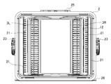
- 2 is a front view of the container body 2
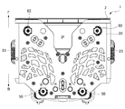
- FIG. 3 is a bottom view of the container body 2
- FIG. 4 is a cross-sectional plan view of the container body 2.
- a substrate storage container 1 shown in FIG. 1 includes a container main body 2 that has an opening on the front surface F and stores a plurality of substrates W, and a lid 4 that closes the opening of the container main body 2. ing.
- Examples of the substrate W stored in the substrate storage container 1 include a semiconductor wafer having a diameter of 300 mm or 450 mm, a mask glass, and the like.
- the container body 2 is a so-called front open box type formed of a front opening frame 2a, a back wall 2b, a right side wall 2c, a left side wall 2d, a top surface 2e, and a bottom surface 2f.
- the lid 4 is detachably attached to the opening of the front opening frame 2 a of the container body 2, and is attached so that a seal gasket (not shown) faces the front opening frame 2 a of the container body 2. Yes.
- the seal gasket is in close contact with the peripheral edge between the container body 2 and the lid 4 and is configured to maintain the airtightness of the internal space of the substrate storage container 1. ing.
- the air in the internal space of the substrate storage container 1 in which the airtightness is maintained is replaced with the gas G by the gas replacement units 3R and 3L described later.
- the rear wall 2b of the container body 2 is further formed with protrusions protruding rearward B on the left and right sides (see FIG. 4).
- the protrusion functions as a leg when placed with the opening on the front F of the container body 2 facing upward.
- a scale for assisting the number of stored substrates W is displayed (see FIG. 1).
- a grip 23 that functions for gripping operation is attached near the center of the outside of the right side wall 2c and the left side wall 2d of the container body 2.
- a plurality of paired left and right support pieces 21 for horizontally supporting the substrate W to be stored are provided inside the right side wall 2c and the left side wall 2d of the container main body 2, respectively, and inside the right side wall 2c and the left side wall 2d.
- position restricting portions 22 that restrict the insertion position of the substrate W when the substrate W is inserted toward the rear B are provided.
- the pair of left and right support pieces 21 are arranged at a predetermined pitch in the vertical direction, and each support piece 21 is formed in an elongated plate shape that supports the periphery of the substrate W.
- the support piece 21 and the auxiliary support piece 21b are provided above the uppermost support piece 21 so that 25 substrates W can be supported (see FIG. 2).
- the maximum storage number is not limited to 25.
- the auxiliary support piece 21b can support the substrate W or a substrate equivalent.
- the substrates W are stored in the container main body 2 in a full state as necessary, or a smaller number than the full state is stored, or the storage position is changed.
- the state varies depending on how the substrate storage container 1 is used. For example, a plurality of substrates W may be stored in an upward or downward direction, or stored alternately.
- a top flange 25 such as a robotic flange is attached to the outside of the top surface 2e of the container body 2.
- the top flange 25 is, for example, gripped by an overhead transport vehicle in a semiconductor manufacturing factory and transported between processes, or used for positioning in a lid opening / closing device such as a semiconductor processing apparatus.
- a bottom plate 26 for positioning and placing the container body 2 is attached to the outside of the bottom surface 2f of the container body 2.
- Accessories such as the container body 2 and the lid body 4, and the grip 23, the top flange 25, and the bottom plate 26 are injection-molded with a molding material containing a required resin, or a combination of a plurality of injection-molded parts. Or configured.
- the resin contained in the molding material include thermoplastic resins such as polycarbonate, cycloolefin polymer, polyetherimide, polyether ketone, polyether ether ketone, polybutylene terephthalate, polyacetal, and liquid crystal polymer, and alloys thereof.
- the container body 2, the lid body 4, the grip 23, the top flange 25, the bottom plate 26, and the like may be any of transparent, opaque, and translucent.
- FIG. 5 is a perspective view of the gas replacement unit 3R
- FIG. 6 is an exploded perspective view of the gas replacement unit 3R
- 7A is a front view
- FIG. 7B is a plan view
- FIG. 7C is a bottom view
- FIG. 7D is a rear view
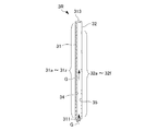
- FIG. 8 is a cross-sectional view of the gas replacement unit 3R taken along the line AA in FIG. 5 to 8 show the gas replacement unit 3R on the right side when viewed from the front F.
- FIG. 5 is a perspective view of the gas replacement unit 3R
- FIG. 6 is an exploded perspective view of the gas replacement unit 3R
- 7A is a front view
- FIG. 7B is a plan view
- FIG. 7C is a bottom view
- FIG. 7D is a rear view
- FIG. 8 is a cross-sectional view of the gas replacement unit 3R taken along the line AA in FIG. 5 to 8 show the gas replacement unit 3R on the right side when viewed from the front F.
- the gas replacement units 3R and 3L replace the internal space of the container main body 2 with the gas G, and the rear B of the container main body 2 (the rear wall 2b or the rear wall 2b or the like so as not to interfere with the substrate W even when the substrate W is inserted). It is provided on both the left and right sides in the vicinity of the protruding portion) with the longitudinal direction being vertical (see FIGS. 1 and 2).
- These gas replacement units 3R and 3L blow out the gas G into the internal space of the container body 2.
- the gas G to be blown out include inert gas and dry air.
- examples of the inert gas include nitrogen gas and argon gas, but nitrogen gas is preferable from the viewpoint of cost.
- three supply valves 50 and one exhaust valve 60 are provided on the bottom surface 2 f of the container body 2.
- the supply valve 50 and the exhaust valve 60 suppress the deterioration of the surface of the stored substrate W by flowing the gas G from the outside of the substrate storage container 1 to the internal space or from the internal space to the outside. It functions to eliminate the pressure difference between the internal space of the storage container 1 and the outside.
- the quantity and arrangement of the air supply valve 50 and the exhaust valve 60 are not limited to the present embodiment, and may be an arrangement in which the two air supply valves 50 and the two exhaust valves 60 are provided. It may be a quantity and an arrangement.
- the two air supply valves 50 are provided on both the left and right sides of the rear B of the bottom surface 2f. And the lower part of gas replacement unit 3R, 3L is connected to these two air supply valves 50 so that the gas G may distribute
- one supply valve 50 and one exhaust valve 60 are provided on the left or right side of the bottom surface 2f near the front face F.
- the air supply valve 50 includes a grommet 50a attached to a recess formed in the bottom surface 2f of the container body 2, a filter member 51 having air permeability attached to an end of the grommet 50a, and a check valve 52. (See FIG. 12).
- the grommet 50a is formed of an elastic resin member such as an elastomer.
- the filter member 51 filters the supplied gas G to remove dust, and a nonwoven fabric filter or the like is used.
- the check valve 52 is urged by a coil spring 53 in the direction of closing the valve and is accommodated in the valve housing 54 (see FIG. 12).
- the exhaust valve 60 has a check valve (not shown) and, for example, a humidity (or concentration) sensor is attached to replace the internal space of the substrate storage container 1 with the gas G, and then the substrate storage container 1 The humidity (or concentration) in the internal space can be measured, and it is possible to manage whether the replacement of the gas G into the internal space of the substrate storage container 1 is normally performed.
- gas replacement unit 3L has the same shape and structure except that it is symmetrical to the gas replacement unit 3R, as shown in FIG.
- the gas replacement unit 3R shown in FIG. 5 includes a housing member 31 and a cover member 32, and is formed in a substantially pentagonal column shape, but the shape is not limited thereto. Further, the gas replacement unit 3R may be formed of the same resin as the container body 2 or the like, or may be formed of a different resin.
- the housing member 31 is formed in a box shape having one open face so as to store the gas G, and the cover member 32 is provided with a locking means (engagement) such as a claw so as to cover the open face. And welding means such as ultrasonic waves.
- the housing member 31 and the cover member 32 form a space for storing the gas G.
- the housing member 31 has two surface portions 31A and 31B which intersect at a predetermined angle and have different sizes.
- the crossing angle between the surface portion 31A and the surface portion 31B is an inner angle in a range of 120 ° to 170 °.
- the area of the surface portion 31A is formed larger than the area of the surface portion 31B.
- a cylindrical connector 311 into which the gas G from the air supply valve 50 flows is provided so as to protrude from the lower surface of the housing member 31.
- a rotation stop projection 312 is formed to stop the rotation of the gas replacement unit 3 ⁇ / b> R in the left-right direction and position the rotation direction (see FIG. 7).
- a cylindrical positioning protrusion 313 for positioning and fixing to the container body 2 is formed on the upper surface of the housing member 31.
- the surface portion 31A of the housing member 31 has horizontally elongated substantially rectangular blow holes in the vertical direction (longitudinal direction) from the top in the first blow holes 31a, 31b, 31c,. .. 31x, 31y, 31z (hereinafter referred to as “first outlet hole group 31a-z” as necessary) are formed at 26 locations at equal intervals (for example, a 10 mm pitch between the centers of the openings). Yes. However, if the respective height positions from the first blow hole 31b of the second stage to the first blow hole 31u are located between the auxiliary support piece 21b and the lowermost support piece 21, they are equally spaced. Not necessarily.
- the surface portion 31B of the housing member 31 has horizontally elongated blow holes, which are arranged in the vertical direction (longitudinal direction) from the top in the order of the third blow holes 33a, 33b, 33c,.
- third blowing hole group 33a-z it is referred to as “third blowing hole group 33a-z”), and is formed at 26 locations at equal intervals (for example, a 10 mm pitch between the centers of the openings).
- the respective height positions from the third blowing hole 31b to the third blowing hole 31u in the second stage are located between the auxiliary support piece 21b and the lowermost support piece 21, they are equally spaced. Not necessarily.
- the blowing direction of the gas G can be made different.
- the gas G easily diffuses into the internal space of the substrate storage container 1.
- the opening height of the uppermost first blowout hole 31a is larger than the opening height of the second blowout first blowout hole 31b. That is, the opening area of the first blowing hole 31a is, for example, about 30% to 50% larger than the opening area of the first blowing hole 31b, but depending on the size of the container body 2 and the amount of blowing air of the gas G, the maximum It can be increased to about 100% (twice).
- the opening height of the first blowing holes 31a is 4 mm
- the opening height of the second blowing holes 31b is 3 mm.
- the opening area from the 1st blowing hole 31b to the 1st blowing hole 31u is normally all equal, and also each height position from the 1st blowing hole 31b to the 1st blowing hole 31u is the auxiliary
- the opening area from the first blowing hole 31v to the first blowing hole 31y is gradually larger than the opening area of the first blowing hole 31u, and the opening area of the first blowing hole 31z is the same as that of the first blowing hole 31y. It is smaller than the opening area. The same applies to the third outlet hole group 33a-z.
- the lowermost first blowing hole 31z and the third blowing hole 33z are supported by at least a position lower than the upper surface of the lowermost support piece 21, that is, the lowermost support piece 21 of the container body 2. It is located at least below the substrate W.
- the number of the first blowing holes 31z and the third blowing holes 33z positioned below the lowermost substrate W is not limited to one, and may be plural.
- the first blow hole group 31a-z and the third blow hole group 33a-z have the opening areas of the uppermost first blow hole 31a and the third blow hole 33a increased, Even if the space formed between the substrate W and the inner surface of the top surface 2e of the container body 2 is larger than the space formed between the substrate W at the other stage and the substrate W at the adjacent stage, Since the air volume of the gas G blown out from the uppermost first blowout hole 31a increases, the humidity or concentration of the gas G in the space above the substrate W does not vary depending on the position (stage) of the substrate W. It becomes a uniform state.
- the first blow hole group 31a-z and the third blow hole group 33a-z have a large opening area on the lower side, even if the straightness of the gas G supplied from below is high, the first blow hole group 31a-z and the third blow hole group 33a-z The gas G is uniformly blown out from below to above the blowing hole group 31a-z and the third blowing hole group 33a-z. Further, since the first blow hole 31z and the third blow hole 33z are also formed under the lowermost substrate W, the gas G is also blown between the lowermost substrate W and the bottom surface 2f. Even if the downflow air in the clean room enters the inside of the opening F of the front surface F of the container body 2, it does not flow more than necessary by the gas G that blows out the upper surface of the bottom surface 2 f toward the front surface F.
- the cover member 32 has substantially rectangular or square blow holes in the vertical direction (longitudinal direction) in order from the top, the second blow holes 32a, 32b, 32e, 32f (hereinafter referred to as “second outlet hole group 32a-f” as necessary) are formed at six locations.
- the height position of the uppermost second blowing hole 32a is substantially the same as the height position of the first blowing hole 31c, and hereinafter, the second blowing hole 32b and the first blowing hole 31h are referred to as the second blowing hole 32c.
- the first blow hole 31m, the second blow hole 32d and the first blow hole 31s, the second blow hole 32e and the first blow hole 31w, the second blow hole 32f and the first blow hole 31y They are almost the same height and match.
- the ratio of the total opening areas S1, S2, and S3 of the first blowing hole group 31a-z, the second blowing hole group 32a-f, and the third blowing hole group 33a-z is stored in the container body 2. Further, it is possible to adjust the humidity variation among the plurality of substrates W to be smaller.
- the adjustment of the opening area can be achieved by preparing the housing member 31 and the cover member 32 having different outlet holes of the first outlet hole group 31a-z, the second outlet hole group 32a-f, and the third outlet hole group 33a-z. It can be carried out by closing an appropriate outlet hole.
- the gas replacement units 3R and 3L are provided on the left and right sides of the rear B (near the rear wall 2b or the protruding portion) of the container body 2 as described above, the blown out gas G is stored in the substrate.
- the air is basically blown out from the first blow hole group 31a-z and the third blow hole group 33a-z toward the front F side, and the air is replaced with the gas G. It will be.
- air also exists in the vicinity of the right side wall 2c or the left side wall 2d from the rear wall 2b on the rear B side from the position where the first outlet group 31a-z and the third outlet group 33a-z are provided. Therefore, it is better to blow out the gas G from the second blowing hole group 32a-f toward the rear B.
- the space on the front side F from the position where the first outlet hole group 31a-z and the third outlet hole group 33a-z are provided is the first outlet hole group 31a-z and the third outlet hole group 33a-z. Is considerably larger than the space on the rear B side than the position where is provided, the total opening area S1 of the first blowing hole group 31a-z facing the front F side and the total opening area of the third blowing hole group 33a-z S3 is preferably larger than the total opening area S2 of the second outlet group 32a-f facing the rear B side.
- the gas replacement units 3R and 3L basically blow out the gas G toward the front F side.
- the gas replacement units 3R and 3L are provided near the right side wall 2c or the left side wall 2d, the right side wall 2c or the left side wall 2d is provided.
- the gas G heading toward the front surface F along the line may be small, but conversely, the gas G heading toward the center of the container body 2 should be large. Therefore, the total opening area S1 of the first blowing hole group 31a-z is preferably larger than the total opening area S3 of the third blowing hole group 33a-z.
- a filter member 34 having air permeability is provided inside the housing member 31, and a filter member 35 having air permeability is also provided inside the cover member 32.
- the filter members 34 and 35 include a nonwoven fabric filter and a porous body.
- the gas G introduced from the cylindrical connector 311 is introduced and stored in a space formed by the housing member 31 and the cover member 32.
- the stored gas G is passed through the filter members 34 and 35 into the internal space of the container body 2 from the first blow hole group 31a-z, the second blow hole group 32a-f, and the third blow hole group 33a-z. Be blown out.
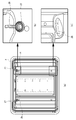
- FIG. 9A is a schematic front view of the container body 2
- FIG. 9B is an enlarged perspective view of the upper portion of the gas replacement unit
- FIG. 9C is an enlarged perspective view of the lower portion of the gas replacement unit.
- FIG. 10 is an enlarged perspective view of the upper mounting portion of the gas replacement unit 3R.
- 11A is an enlarged view of the lower mounting portion of the gas replacement unit 3R, and FIG.
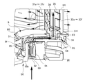
- the gas replacement unit 3 ⁇ / b> R is attached to the container body 2 by a positioning and fixing member 8 and an offset member 9. Specifically, the upper part of the gas replacement unit 3R is attached to the positioning fixing member 8, and the lower part of the gas replacement unit 3R is attached to the offset member 9.
- a circular through hole 27 is formed on both the left and right sides of the back wall 2b of the container body 2 in order to fix the positioning fixing member 8, and a stopper 28 is formed above the through hole 27.
- attachment holes 29 are formed on the left and right sides of the bottom surface 2 f of the container body 2 in order to fix the offset member 9.
- the mounting hole 29 is not circular but is formed in a substantially elliptical shape connecting a large circle and a small circle.
- the positioning and fixing member 8 shown in FIG. 10 has an elongated shape, and is formed of a shaft having one end side substantially plate-like and the other end side rectangular. Around this shaft, three disc-shaped flanges 81, 82, 83 are formed toward the other end side.
- the shaft end flange 83 and the intermediate flange 82 are formed smaller than the diameter of the through hole 27 in the back wall 2 b and are inserted into the through hole 27.
- a small-diameter step portion is formed on the intermediate flange 82, and an O-ring 84A is fitted therein.
- a small-diameter stepped portion is also formed on the inner flange 81, and an O-ring 84B is fitted therein.
- the inner flange 81 and the O-ring 84 ⁇ / b> B are formed larger than the diameter of the through hole 27, and the O-ring is interposed between the container body 2 and the flange 81 when the other end side of the positioning fixing member 8 is inserted into the through hole 27. Since 84B is sandwiched, the gas G does not leak.
- a C-ring 85 is formed on the rectangular shaft located between the shaft-end flange 83 and the container body 2 with a rectangular inner side and an outer diameter larger than the through-hole 27.
- the positioning fixing member 8 is fixed to the container body 2 through the through hole 27.
- the sealing performance is enhanced by inserting the C-ring 85 while the O-ring 84B is crushed between the flange 81 and the container body 2 while pulling the flange 83 at the shaft end outward.
- one end side of the positioning and fixing member 8 is formed in a plate shape bent upward and has an elongated slit 86 formed therein.
- the positioning projection 313 and the stopper 28 of the housing member 31 are fitted into the slit 86.
- the end portion 87 is further curved upward, and a U-shaped notch 88 is formed at the distal end thereof.
- the offset member 9 shown in FIG. 11 is formed such that a gap through which the gas G flows is formed between the offset plate press 90 positioned inside the bottom surface 2f and the offset plate 95 positioned outside the bottom surface 2f. , Assembled through an O-ring 94.
- the offset plate holder 90 is formed with a recess 92 into which the rotation projection 312 of the housing member 31 is fitted.
- the rotation projection 312 is fitted into the recess 92 so that the direction of the rotating gas replacement unit 3R and The position is determined.
- a hole for inserting the connector 311 of the gas replacement unit 3 ⁇ / b> R is formed in the offset plate retainer 90, and the connector 311 is inserted via the packing 93.
- the offset plate presser 90 is fitted into the mounting hole 29 via an O-ring 91.
- the offset plate 95 has a recess into which the air supply valve 50 is fitted so that the center of the air supply valve 50 is located at a position shifted from the center position of the packing 93 in plan view.
- the lower connector 311 is attached to the offset member 9, and then the upper positioning protrusion 313 is attached to the positioning fixing member 8 and attached to the container body 2.
- the positioning protrusion 313 at the upper part of the gas replacement unit 3R is pushed from the end 87 side toward the slit 86 from the state in which the lower connector 311 of the gas replacement unit 3R is inserted into the packing 93 and tilted.
- the positioning fixing member 8 is curved, and the positioning projection 313 is fitted into the slit 86.
- the positioning projection 313 also comes into contact with the stopper 28, whereby the position in the slit 86 is determined, and the upper portion of the gas replacement unit 3R is positioned and fixed.
- FIG. 12 is a cross-sectional perspective view showing the flow of the gas G flowing from the air supply valve 50.
- the flow of gas G is indicated by arrows.
- the gas G introduced at high pressure from the air supply valve 50 passes through the filter member 51, flows through the gap between the offset plate press 90 and the offset plate 95, and the rear B offset plate press 90 and the gas replacement unit. It heads for a connection part with the connection tool 311 of the lower part of 3R.
- the gas G is blown out from the first blowing hole group 31a-z, the third blowing hole group 33a-z, and the second blowing hole group 32a-f while proceeding through the storage space of the gas replacement unit 3R (see FIG. 8).
- the gas G is blown out in three different directions, that is, the direction toward the center on the front F side and the direction toward the right side wall 2c, and the direction toward the rear side wall 2b on the rear B side (see FIG. 4).
- the extending direction of the blowout opening of the first blowout hole group 31a-z or the third blowout hole group 33a-z that is, the surface portion 31A on which the first blowout hole group 31a-z or the third blowout hole group 33a-z is formed or It is preferable that the normal passing through the center of the surface portion 31B is a range that reaches the opening of the front opening frame 2a of the container body 2 without intersecting the right side wall 2c or the left side wall 2d. More preferably, in the case of the gas replacement unit 3R, the normal of the surface portion 31A is in the range of 10 ° to 40 ° with respect to the normal NL (perpendicular) from the opening of the front opening frame 2a of the container body 2.
- the normal of the surface portion 31B is in the range of 5 ° from the center side to 10 ° from the right side wall 2c across the normal NL (perpendicular line) from the opening of the front opening frame 2a of the container body 2.
- the gas replacement unit 3L is symmetrical with the gas replacement unit 3R.
- the surface portion 31A and the surface portion 31B (or the first blowing hole group 31a-z and the third blowing hole group 33a-z) are formed so as to be in such a range, and the gas replacement units 3R and 3L are connected to the container body 2.
- the gas G blown out from each blowing hole does not collide with and reflect on the right side wall 2c or the left side wall 2d of the container body 2. For this reason, since the turbulence of the gas G does not occur, the internal space of the container body 2 can be quickly and reliably replaced with the gas G.
- FIG. 13 shows (a) a comparative example and (b) an example showing the experimental results of gas replacement.
- Example 2 A gas in which the opening area of the uppermost first blowing hole 31a is larger than the opening area of the first blowing hole 31b, and the opening area of the uppermost third blowing hole 33a is larger than the opening area of the third blowing hole 33b.
- the replacement units 3R and 3L are attached to the substrate storage container 1, and the gas G is purged with an air flow of 90 L / min (per unit) to store the change in humidity in the substrate storage container 1. Further, for each stage of the substrate W (# 1 to # 25), measurement was performed for the vicinity of the front vertex (F position) and the vicinity of the right vertex (R position). The substrate storage container 1 was installed in an environment with a downflow of 0.4 m / s with the lid 4 removed. At this time, the differential pressure between the inside and the outside of the container body 2 was 1.7 Pa.
- the gas replacement units 3R and 3L shown in FIG. 7 are the same as the opening area of the first blowing hole 31b in the uppermost first blowing hole 31a.
- a hole 33a having the same opening area as the third blowing hole 33b was used.
- the humidity value and the transition state (replacement completion time) in the space above the uppermost substrate W were far from those of the other stages.
- the humidity value and the transition state in the space above the substrate W did not vary regardless of the stage of the substrate W accommodated.
- the substrate storage container 1 has an opening on the front surface, a container body 2 that can store a plurality of substrates W, a lid 4 that closes the opening, and a container.
- An air supply valve 50 for supplying the gas G from the outside of the main body 2 to the internal space, and gas replacement units 3R and 3L for blowing the gas G supplied from the air supply valve 50 to the internal space of the container main body 2;
- a substrate storage container 1 having an air supply valve 50 attached to the rear B of the bottom surface 2f of the container body 2, and the gas replacement units 3R and 3L include a housing member 31 for storing the gas G supplied from the air supply valve 50, , And a cover member 32 that covers the opening of the housing member 31, and the housing member 31 blows out the stored gas G in the front direction of the container body 2, and a plurality of first blowout holes 31 a, 31 b, 31 c. 31x, 31y, 31z up and down Has an opening area of the first air hole 31a of the
- the gas G blown out from the first blowing holes 31a of the gas replacement units 3R and 3L creates a space formed between the substrate W accommodated in the uppermost stage and the inner surface of the top surface 2e of the container body 2. It flows toward the front F direction. Therefore, even when the storage state of the substrate W changes, it is possible to provide the substrate storage container 1 with less variation in humidity or concentration between the substrates W.
- At least one of the first blowout hole groups 31a-z is positioned below the lowermost substrate W stored in the container body 2.
- the gas G can be made to flow evenly under the lowermost substrate W. Therefore, even when the storage state of the substrate W changes, it is possible to provide the substrate storage container 1 with less variation in humidity between the substrates W.
- the gas replacement units 3 ⁇ / b> R and 3 ⁇ / b> L include a filter member 34 having air permeability inside the housing member 31. Thereby, even if dust is contained in the supplied gas G, since it is captured by the filter member 34, it does not blow out into the container body 2, and the internal space of the substrate storage container 1 is not contaminated. .
- At least one of the upper part or the center part of the housing member 31 is positioned and fixed by using the through hole 27 formed in the back wall 2b of the container body 2.
- the gas replacement units 3R and 3L are attached using the positioning fixing member 8 that can be easily attached to and detached from the through hole 27, the gas replacement units 3R and 3L can be easily attached or detached from the container body 2.
- the gas replacement units 3R and 3L can be easily removed, and the interior of the container body 2 can be cleaned to every corner. Further, the removed gas replacement units 3R and 3L can be easily cleaned.
- the gas G is nitrogen gas or dry air.
- the opening area, the number, and the arrangement of the first blowing hole group 31a-z, the third blowing hole group 33a-z, and the second blowing hole 32a-f are not limited to the embodiment. You may comprise so that the amount of blowing air below may be increased so that it can oppose air from the outside, such as downflow air blowing along the upper surface of the bottom face 2f.
- the ratio of the blown air volume in the front F direction and the rear B direction may be adjusted by selectively closing or additionally drilling the second blow hole group 32a-f. Furthermore, you may change the direction of gas replacement unit 3R, 3L by changing the position of the recessed part 12 of the offset member 9. FIG. Alternatively, the ratio of the blowing direction and / or the amount of blowing air may be adjusted by changing the crossing angle between the two surface portions 31A and 31B of the housing member 31 or changing the area. These changes can be dealt with by using nesting in the molding die.
- the housing member 31 may be positioned and fixed at the central portion instead of the upper portion, or may be positioned and fixed at the upper portion and the central portion. At this time, the position of the through hole 27 formed in the back wall 2b may be changed as appropriate, and the shape of the positioning fixing member 8 may be changed as appropriate. Furthermore, the housing member 31 is not limited to being positioned and fixed to the container body 2, and the cover member 32 constituting the gas replacement units 3 ⁇ / b> R and 3 ⁇ / b> L may be positioned and fixed to the container body 2.
- a plurality of other gas replacement units may be provided, or conversely, any one of the gas replacement units 3R or 3L may be provided.
- the opening area of the uppermost first blowing hole 31a is set to the opening of the second blowing outlet 31b. It may be larger than the area.
- gas replacement units 3R and 3L are not limited to the left and right two positions on the rear B, and may be arranged in the area where there is no interference with the substrate W in the center of the rear B.
Landscapes
- Container, Conveyance, Adherence, Positioning, Of Wafer (AREA)
- Packaging Frangible Articles (AREA)
- Packages (AREA)
- Chemical & Material Sciences (AREA)
- Chemical Kinetics & Catalysis (AREA)
Abstract
Description
(2)上記(1)の態様において、前記第1吹出孔の少なくとも1つは、前記容器本体に収納された最下段の前記基板よりも下方に位置してもよい。
(3)上記(1)又は(2)の態様において、前記気体置換ユニットは、前記ハウジング部材の内側に通気性を有するフィルタ部材を含んでもよい。
(4)上記(1)から(3)までのいずれか1つの態様において、前記気体置換ユニットの上部又は中央部の少なくとも一方が、前記容器本体の背面壁に形成された貫通孔を用いて位置決め固定されてもよい。
(5)上記(1)から(4)までのいずれか1つの態様において、前記気体は、窒素ガス又はドライエアであってもよい。
(6)本発明に係る別の1つの態様は、前面に開口部を有し、複数枚の基板を収納可能な容器本体と、前記開口部を閉鎖する蓋体と、前記容器本体の外部から内部空間に気体を供給する給気弁と、前記給気弁から供給された前記気体を前記容器本体の内部空間に吹出す気体置換ユニットと、を備え、前記容器本体の底面の後方に前記給気弁を取付けた基板収納容器用の気体置換ユニットであって、前記給気弁から供給された前記気体を貯留するハウジング部材と、前記ハウジング部材の開口を覆うカバー部材と、を含み、前記ハウジング部材は、貯留された前記気体を前記容器本体の正面方向に吹出す複数の第1吹出孔を上下方向に有し、最上段の前記第1吹出孔の開口面積は、2段目の前記第1吹出孔の開口面積よりも大きいものである。
図1に示される基板収納容器1は、正面Fに開口部を有し、複数枚の基板Wを収納する容器本体2と、この容器本体2の開口部を閉鎖する蓋体4と、を備えている。基板収納容器1に収納される基板Wとしては、直径が300mmや450mmの半導体ウエハ、マスクガラスなどが挙げられる。
図12において、給気弁50から高圧で導入された気体Gは、フィルタ部材51を通過し、オフセットプレート押さえ90とオフセットプレート95との隙間を流れ、後方Bのオフセットプレート押さえ90と気体置換ユニット3Rの下部の接続具311との接続部に向かう。
最上段の第1吹出孔31aの開口面積が、第1吹出孔31bの開口面積よりも大きく、最上段の第3吹出孔33aの開口面積が、第3吹出孔33bの開口面積よりも大きい気体置換ユニット3R,3L(図7参照)を、基板収納容器1に取付けて、気体Gを90L/min(1個当たり)の風量でパージし、基板収納容器1内の湿度の推移を、収納された基板Wの段ごと(#1から#25)に、正面側の頂点付近(F位置)、右側の頂点付近(R位置)について測定した。なお、基板収納容器1は、蓋体4が取外された状態で、ダウンフローが0.4m/sの環境に設置した。このとき、容器本体2の内部と外部との差圧は、1.7Paであった。
比較例では、図7に示した気体置換ユニット3R,3Lを、最上段の第1吹出孔31aの開口面積が、第1吹出孔31bの開口面積と同じ大きさで、最上段の第3吹出孔33aの開口面積が、第3吹出孔33bの開口面積と同じ大きさにしたものを用いた。
実施形態の気体置換ユニット3R,3Lにおいて、第1吹出孔群31a-z、第3吹出孔群33a-z及び第2吹出孔32a-fの開口面積や数量や配置も実施形態に限らず、底面2fの上面に沿って吹き込むダウンフローエアなどの外部からエアに対向できるように、下方の吹出風量を増やすように構成してもよい。
2 容器本体、2a 正面開口枠、2b 背面壁、2c 右側壁、2d 左側壁、2e 天面、2f 底面
21 支持片、21b 補助支持片
22 位置規制部
23 グリップ
25 トップフランジ
26 ボトムプレート
27 貫通孔
28 ストッパ
29 取付孔
3R,3L 気体置換ユニット
31 ハウジング部材、31A,31B 面部、311 接続具、312 回止め突起、313 位置決め突起
32 カバー部材
31a・・・31z 第1吹出孔
32a・・・32f 第2吹出孔
33a・・・33z 第3吹出孔
34,35 フィルタ部材
4 蓋体
50 給気弁、50a グロメット、51 フィルタ部材、52 逆止弁、53 コイルバネ、54 バルブハウジング
60 排気弁
8 位置決め固定部材
81,82,83 フランジ
84A,84B Oリング
85 Cリング
86 スリット
87 端部
88 切欠き
9 オフセット部材
90 オフセットプレート押さえ
91 Oリング
92 凹部
93 パッキン
94 Oリング
95 オフセットプレート
F 正面
B 後方
G 気体
W 基板
NL 法線
Claims (6)
- 前面に開口部を有し、複数枚の基板を収納可能な容器本体と、
前記開口部を閉鎖する蓋体と、
前記容器本体の外部から内部空間に気体を供給する給気弁と、
前記給気弁から供給された前記気体を前記容器本体の内部空間に吹出す気体置換ユニットと、を備え、
前記容器本体の底面の後方に前記給気弁を取付けた基板収納容器であって、
前記気体置換ユニットは、
前記給気弁から供給された前記気体を貯留するハウジング部材と、
前記ハウジング部材の開口を覆うカバー部材と、を含み、
前記ハウジング部材は、貯留された前記気体を前記容器本体の正面方向に吹出す複数の第1吹出孔を上下方向に有し、
最上段の前記第1吹出孔の開口面積は、2段目の前記第1吹出孔の開口面積よりも大きい
ことを特徴とする基板収納容器。 - 前記第1吹出孔の少なくとも1つは、前記容器本体に収納された最下段の前記基板よりも下方に位置する
ことを特徴とする請求項1に記載の基板収納容器。 - 前記気体置換ユニットは、前記ハウジング部材の内側に通気性を有するフィルタ部材を含む
ことを特徴とする請求項1又は2に記載の基板収納容器。 - 前記気体置換ユニットの上部又は中央部の少なくとも一方が、前記容器本体の背面壁に形成された貫通孔を用いて位置決め固定される
ことを特徴とする請求項1から3までのいずれか1項に記載の基板収納容器。 - 前記気体は、窒素ガス又はドライエアである
ことを特徴とする請求項1から4までのいずれか1項に記載の基板収納容器。 - 前面に開口部を有し、複数枚の基板を収納可能な容器本体と、
前記開口部を閉鎖する蓋体と、
前記容器本体の外部から内部空間に気体を供給する給気弁と、を備え、
前記容器本体の底面の後方に前記給気弁を取付けた基板収納容器用の気体置換ユニットであって、
前記給気弁から供給された前記気体を貯留するハウジング部材と、
前記ハウジング部材の開口を覆うカバー部材と、を含み、
前記ハウジング部材は、貯留された前記気体を前記容器本体の正面方向に吹出す複数の第1吹出孔を上下方向に有し、
最上段の前記第1吹出孔の開口面積は、2段目の前記第1吹出孔の開口面積よりも大きい
ことを特徴とする気体置換ユニット。
Priority Applications (3)
| Application Number | Priority Date | Filing Date | Title |
|---|---|---|---|
| JP2018563230A JP7226684B2 (ja) | 2017-01-18 | 2017-12-20 | 基板収納容器 |
| KR1020197017394A KR102465301B1 (ko) | 2017-01-18 | 2017-12-20 | 기판 수납 용기 및 기체 치환 유닛 |
| US16/471,177 US11488850B2 (en) | 2017-01-18 | 2017-12-20 | Substrate storage container and gas replacement unit |
Applications Claiming Priority (2)
| Application Number | Priority Date | Filing Date | Title |
|---|---|---|---|
| JP2017006998 | 2017-01-18 | ||
| JP2017-006998 | 2017-01-18 |
Publications (1)
| Publication Number | Publication Date |
|---|---|
| WO2018135222A1 true WO2018135222A1 (ja) | 2018-07-26 |
Family
ID=62907956
Family Applications (1)
| Application Number | Title | Priority Date | Filing Date |
|---|---|---|---|
| PCT/JP2017/045724 Ceased WO2018135222A1 (ja) | 2017-01-18 | 2017-12-20 | 基板収納容器及び気体置換ユニット |
Country Status (5)
| Country | Link |
|---|---|
| US (1) | US11488850B2 (ja) |
| JP (1) | JP7226684B2 (ja) |
| KR (1) | KR102465301B1 (ja) |
| TW (1) | TWI761416B (ja) |
| WO (1) | WO2018135222A1 (ja) |
Cited By (1)
| Publication number | Priority date | Publication date | Assignee | Title |
|---|---|---|---|---|
| JP2025127448A (ja) * | 2024-02-20 | 2025-09-01 | 中勤實業股▲ふん▼有限公司 | 流体を進入させる気体拡散装置を有する基板容器 |
Families Citing this family (3)
| Publication number | Priority date | Publication date | Assignee | Title |
|---|---|---|---|---|
| US11104496B2 (en) * | 2019-08-16 | 2021-08-31 | Gudeng Precision Industrial Co., Ltd. | Non-sealed reticle storage device |
| JP7733135B2 (ja) * | 2021-05-27 | 2025-09-02 | インテグリス・インコーポレーテッド | 直径が拡大されたパージポートを有する半導体基板搬送容器 |
| KR20240115341A (ko) | 2021-12-17 | 2024-07-25 | 엔테그리스, 아이엔씨. | 반도체 기판 운반 용기 내에 퍼지 유체 조절 요소를 설치하는 방법 |
Citations (5)
| Publication number | Priority date | Publication date | Assignee | Title |
|---|---|---|---|---|
| JPH09330884A (ja) * | 1996-06-07 | 1997-12-22 | Sony Corp | エピタキシャル成長装置 |
| JP2011187884A (ja) * | 2010-03-11 | 2011-09-22 | Hitachi Kokusai Electric Inc | 基板処理装置 |
| JP2015176976A (ja) * | 2014-03-14 | 2015-10-05 | ミライアル株式会社 | 基板収納容器 |
| JP2016004949A (ja) * | 2014-06-18 | 2016-01-12 | 信越ポリマー株式会社 | 基板収納容器 |
| JP2016225352A (ja) * | 2015-05-27 | 2016-12-28 | 信越ポリマー株式会社 | 基板収納容器 |
Family Cites Families (11)
| Publication number | Priority date | Publication date | Assignee | Title |
|---|---|---|---|---|
| US5879458A (en) * | 1996-09-13 | 1999-03-09 | Semifab Incorporated | Molecular contamination control system |
| US6875282B2 (en) * | 2001-05-17 | 2005-04-05 | Ebara Corporation | Substrate transport container |
| EP1388165B1 (en) * | 2001-05-17 | 2007-03-07 | Ebara Corporation | Substrate transport container |
| JP4204302B2 (ja) | 2002-10-25 | 2009-01-07 | 信越ポリマー株式会社 | 収納容器 |
| KR100505061B1 (ko) * | 2003-02-12 | 2005-08-01 | 삼성전자주식회사 | 기판 이송 모듈 |
| US7758338B2 (en) * | 2007-05-29 | 2010-07-20 | Taiwan Semiconductor Manufacturing Co., Ltd. | Substrate carrier, port apparatus and facility interface and apparatus including same |
| CN102017119B (zh) * | 2008-03-13 | 2014-01-01 | 安格斯公司 | 具有管状环境控制部件的晶圆容器 |
| TWM453233U (zh) * | 2013-01-07 | 2013-05-11 | 家登精密工業股份有限公司 | 應用於基板收納容器的氣體填充裝置 |
| EP4235759A3 (en) * | 2013-10-14 | 2023-10-04 | Entegris, Inc. | Towers for substrate carriers |
| WO2016002005A1 (ja) * | 2014-07-01 | 2016-01-07 | ミライアル株式会社 | 基板収納容器 |
| WO2018047541A1 (ja) * | 2016-09-06 | 2018-03-15 | 信越ポリマー株式会社 | 基板収納容器及び気体置換ユニット |
-
2017
- 2017-12-20 US US16/471,177 patent/US11488850B2/en active Active
- 2017-12-20 KR KR1020197017394A patent/KR102465301B1/ko active Active
- 2017-12-20 JP JP2018563230A patent/JP7226684B2/ja active Active
- 2017-12-20 WO PCT/JP2017/045724 patent/WO2018135222A1/ja not_active Ceased
-
2018
- 2018-01-05 TW TW107100451A patent/TWI761416B/zh active
Patent Citations (5)
| Publication number | Priority date | Publication date | Assignee | Title |
|---|---|---|---|---|
| JPH09330884A (ja) * | 1996-06-07 | 1997-12-22 | Sony Corp | エピタキシャル成長装置 |
| JP2011187884A (ja) * | 2010-03-11 | 2011-09-22 | Hitachi Kokusai Electric Inc | 基板処理装置 |
| JP2015176976A (ja) * | 2014-03-14 | 2015-10-05 | ミライアル株式会社 | 基板収納容器 |
| JP2016004949A (ja) * | 2014-06-18 | 2016-01-12 | 信越ポリマー株式会社 | 基板収納容器 |
| JP2016225352A (ja) * | 2015-05-27 | 2016-12-28 | 信越ポリマー株式会社 | 基板収納容器 |
Cited By (1)
| Publication number | Priority date | Publication date | Assignee | Title |
|---|---|---|---|---|
| JP2025127448A (ja) * | 2024-02-20 | 2025-09-01 | 中勤實業股▲ふん▼有限公司 | 流体を進入させる気体拡散装置を有する基板容器 |
Also Published As
| Publication number | Publication date |
|---|---|
| JP7226684B2 (ja) | 2023-02-21 |
| KR20190102188A (ko) | 2019-09-03 |
| TWI761416B (zh) | 2022-04-21 |
| JPWO2018135222A1 (ja) | 2019-11-07 |
| KR102465301B1 (ko) | 2022-11-11 |
| TW201829266A (zh) | 2018-08-16 |
| US11488850B2 (en) | 2022-11-01 |
| US20190393062A1 (en) | 2019-12-26 |
Similar Documents
| Publication | Publication Date | Title |
|---|---|---|
| WO2018047541A1 (ja) | 基板収納容器及び気体置換ユニット | |
| JP6953661B2 (ja) | 基板収納容器 | |
| WO2018135222A1 (ja) | 基板収納容器及び気体置換ユニット | |
| JP5241607B2 (ja) | 基板収納容器 | |
| KR102798614B1 (ko) | 기판수납용기 | |
| JP3960787B2 (ja) | 精密基板収納容器 | |
| JP6367153B2 (ja) | 基板収納容器 | |
| JP6431440B2 (ja) | 基板収納容器 | |
| JP7234476B2 (ja) | 基板収納容器 | |
| JP6553498B2 (ja) | 基板収納容器 | |
| JP7351681B2 (ja) | 基板収納容器 | |
| JP7651419B2 (ja) | 基板収納容器 |
Legal Events
| Date | Code | Title | Description |
|---|---|---|---|
| 121 | Ep: the epo has been informed by wipo that ep was designated in this application |
Ref document number: 17892539 Country of ref document: EP Kind code of ref document: A1 |
|
| ENP | Entry into the national phase |
Ref document number: 20197017394 Country of ref document: KR Kind code of ref document: A |
|
| ENP | Entry into the national phase |
Ref document number: 2018563230 Country of ref document: JP Kind code of ref document: A |
|
| NENP | Non-entry into the national phase |
Ref country code: DE |
|
| 122 | Ep: pct application non-entry in european phase |
Ref document number: 17892539 Country of ref document: EP Kind code of ref document: A1 |