WO2018135181A1 - カメラ装置およびカメラ装置の温度測定方法 - Google Patents
カメラ装置およびカメラ装置の温度測定方法 Download PDFInfo
- Publication number
- WO2018135181A1 WO2018135181A1 PCT/JP2017/044381 JP2017044381W WO2018135181A1 WO 2018135181 A1 WO2018135181 A1 WO 2018135181A1 JP 2017044381 W JP2017044381 W JP 2017044381W WO 2018135181 A1 WO2018135181 A1 WO 2018135181A1
- Authority
- WO
- WIPO (PCT)
- Prior art keywords
- camera
- housing
- infrared
- camera unit
- camera device
- Prior art date
- Legal status (The legal status is an assumption and is not a legal conclusion. Google has not performed a legal analysis and makes no representation as to the accuracy of the status listed.)
- Ceased
Links
Images






Classifications
-
- H—ELECTRICITY
- H04—ELECTRIC COMMUNICATION TECHNIQUE
- H04N—PICTORIAL COMMUNICATION, e.g. TELEVISION
- H04N23/00—Cameras or camera modules comprising electronic image sensors; Control thereof
- H04N23/50—Constructional details
- H04N23/51—Housings
-
- G—PHYSICS
- G03—PHOTOGRAPHY; CINEMATOGRAPHY; ANALOGOUS TECHNIQUES USING WAVES OTHER THAN OPTICAL WAVES; ELECTROGRAPHY; HOLOGRAPHY
- G03B—APPARATUS OR ARRANGEMENTS FOR TAKING PHOTOGRAPHS OR FOR PROJECTING OR VIEWING THEM; APPARATUS OR ARRANGEMENTS EMPLOYING ANALOGOUS TECHNIQUES USING WAVES OTHER THAN OPTICAL WAVES; ACCESSORIES THEREFOR
- G03B15/00—Special procedures for taking photographs; Apparatus therefor
-
- G—PHYSICS
- G03—PHOTOGRAPHY; CINEMATOGRAPHY; ANALOGOUS TECHNIQUES USING WAVES OTHER THAN OPTICAL WAVES; ELECTROGRAPHY; HOLOGRAPHY
- G03B—APPARATUS OR ARRANGEMENTS FOR TAKING PHOTOGRAPHS OR FOR PROJECTING OR VIEWING THEM; APPARATUS OR ARRANGEMENTS EMPLOYING ANALOGOUS TECHNIQUES USING WAVES OTHER THAN OPTICAL WAVES; ACCESSORIES THEREFOR
- G03B17/00—Details of cameras or camera bodies; Accessories therefor
- G03B17/02—Bodies
-
- G—PHYSICS
- G03—PHOTOGRAPHY; CINEMATOGRAPHY; ANALOGOUS TECHNIQUES USING WAVES OTHER THAN OPTICAL WAVES; ELECTROGRAPHY; HOLOGRAPHY
- G03B—APPARATUS OR ARRANGEMENTS FOR TAKING PHOTOGRAPHS OR FOR PROJECTING OR VIEWING THEM; APPARATUS OR ARRANGEMENTS EMPLOYING ANALOGOUS TECHNIQUES USING WAVES OTHER THAN OPTICAL WAVES; ACCESSORIES THEREFOR
- G03B17/00—Details of cameras or camera bodies; Accessories therefor
- G03B17/02—Bodies
- G03B17/08—Waterproof bodies or housings
-
- G—PHYSICS
- G03—PHOTOGRAPHY; CINEMATOGRAPHY; ANALOGOUS TECHNIQUES USING WAVES OTHER THAN OPTICAL WAVES; ELECTROGRAPHY; HOLOGRAPHY
- G03B—APPARATUS OR ARRANGEMENTS FOR TAKING PHOTOGRAPHS OR FOR PROJECTING OR VIEWING THEM; APPARATUS OR ARRANGEMENTS EMPLOYING ANALOGOUS TECHNIQUES USING WAVES OTHER THAN OPTICAL WAVES; ACCESSORIES THEREFOR
- G03B17/00—Details of cameras or camera bodies; Accessories therefor
- G03B17/56—Accessories
Definitions
- the present invention relates to a camera device and a temperature measurement method for the camera device.
- the temperature in the housing is measured by the temperature detection unit so that clear and stable shooting can be performed, and the temperature is measured according to the measured temperature. Therefore, it is required to correct the output value of the infrared sensor. Regarding this matter, there is room for improvement in the conventional camera device.
- An object of the present invention is to provide a camera device and a temperature measurement method for the camera device that can stably perform temperature measurement in the housing by the temperature measurement unit, and thus correction of the output value of the infrared sensor.
- the camera device includes: A housing having a housing and a lid; A camera unit mounted with an infrared camera and housed in the housing;
- the infrared camera has an infrared lens, a lens barrel that holds the infrared lens, and an infrared sensor that detects infrared rays received through the infrared lens,
- the housing includes a temperature detection unit that detects a temperature inside the housing at a position in contact with the lens barrel when the camera unit is housed.
- the temperature measuring method of the camera device is: In a camera device in which a camera unit equipped with an infrared camera having a lens barrel for holding an infrared lens is detachable from a housing having a housing and a lid, An internal temperature of the housing is measured by a temperature detector provided in the housing and in contact with the lens barrel.
- the present invention it is possible to stably perform the temperature measurement in the casing by the temperature measuring unit, and hence the correction of the output value of the infrared sensor.
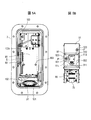
- FIGS. 5A and 5B are diagrams illustrating the relationship between the housing and the camera unit, in which FIG. 5A shows a plan view of the housing with the lid removed, and FIG. 5B shows a plan view of the camera unit. It is a notch sectional view which shows the structure of the thermocouple and leaf
- FIG. 1 is an external perspective view of the camera apparatus 1 according to the present embodiment.
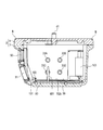
- FIG. 2 is a cross-sectional view of the housing 2 in the camera device 1
- FIG. 3 is an external perspective view of the camera unit 5 housed in the housing 2.
- the camera apparatus 1 includes a housing 2 in which a camera unit 5 described later with reference to FIG.
- the housing 2 includes a housing 3 that houses the camera unit 5 and a lid 4 that is attached to the housing 3.
- the housing 3 and the lid 4 are made of a material having high rigidity such as metal in order to have an explosion-proof specification.
- the housing 3 has a box shape having a size and a volume capable of accommodating the camera unit 5, and as shown in FIG. 1, circular windows 31 and 32 made of a translucent member are provided on one side surface. ing.
- the window 31 is an infrared window provided at a position corresponding to an infrared lens 61 of an infrared camera 60 described later of the camera unit 5, and the window 32 is a lens of a visible light camera 70 described later of the camera unit 5. It is the visible window provided in the position corresponding to.
- FIG. 2 is a cross-sectional view of the housing 2 before the camera unit 5 is housed.
- the infrared window 31 is provided to be inclined so as to face the lower side than the horizontal.
- one side surface of the housing 3 in which the windows 31 and 32 are provided is inclined in a direction in which a lower portion where the infrared window 31 is disposed becomes wider from the bottom surface of the housing 3, and the inclined portion.
- the window frame of the outer surface side of the infrared window 31 is attached to.
- the upper part of the housing 3 in which the visible window 32 is provided extends in a substantially vertical direction, and the visible window 32 and its window frame are not inclined.
- a cable for supplying power to the camera unit 5 and a cable for transmitting and receiving signals between the camera unit 5 and external devices are provided on the other side surface of the housing 3.
- a plurality (four in this example) of holes 33A to 33D for insertion are provided.
- the floor surface 30 of the housing 3 is provided with a substrate 80 for mounting other components described later.
- the lid 4 is a substantially rectangular member in plan view. As shown in FIG. 2, the periphery of the lower surface of the lid 4 is joined to the upper periphery of the housing 3 in a flange shape, so that the interior of the housing 2 is Sealed. In addition, a grip portion 41 that is gripped by the user when the lid 4 is opened and closed is provided at substantially the center of the upper surface of the lid 4.
- FIG. 1 shows a state in which the lid 4 is attached to the housing 3 using a plurality (12 in this example) of hexagon socket head bolts (hereinafter simply referred to as bolts) B and the inside is sealed.
- bolts hexagon socket head bolts
- each bolt B has a retaining portion for the lid 4 so that it does not fall off from the lid 4.
- FIG. 3 shows the configuration of the camera unit 5
- FIG. 4 shows a state where the camera cover 51 is removed from the camera unit 5.
- 5A and 5B are views of the housing 3 and the camera unit 5 as viewed from above.
- the camera unit 5 includes an infrared lens 61, an infrared sensor 62, and the like on a flat camera base 50 that is a base member and serves as a base.
- a camera 60, a visible light camera 70 such as a CCD camera, and various components described below are mounted.
- Such a camera unit 5 can be installed and used at a high place, for example, as a gas detection device by being housed in the case 2 having high dustproof, waterproof and explosion-proof properties as described above. .
- the adjustment of the optical system such as the focus and parallax in the infrared camera 60 and the visible light camera 70 is adjusted locally from the viewpoint of safety. It is preferable that the adjustment is sufficiently made in advance at the time of manufacture or shipment.
- the weight of the product particularly the weight of the housing 2 becomes heavy, and if it is attempted to collect the entire device during maintenance, it is necessary to perform it by crane work, etc. Since it is large and expensive, it is better to have a structure in which only the camera unit 5 is attached and detached.
- components such as the infrared camera 60 and the visible light camera 70 that require adjustment work in advance are mounted on the camera unit 5 side, and the camera unit 5 can be attached to and detached from the housing 3.
- the adjusted cameras 60, 70, etc. can be exchanged at once on site.
- the configuration of the camera unit 5 will be described, assuming that the side on which the infrared lens 61 and the visible light camera 70 are disposed in the housing 3 and the camera unit 5 is the “front side”.
- prismatic columnar portions 52 are respectively provided upright from the left and right corners, and a hood 53 having a substantially “inverted U” shape in a front view is fixed to the columnar portions 52.
- the hood 53 covers the infrared lens 61 and the lens barrel 63 to which the lens 61 is attached.
- the lens barrel 63 of the infrared camera 60 adjusts the position in the vertical and horizontal directions with respect to the lens barrel fixing portion 54 (see FIG. 9) erected on the camera base 50, and a plurality of screws are attached to the lens barrel fixing portion 54. By fixing, it fixes to the front side of the camera base 50 so that it may be arrange
- a sensor fixing base 64 is attached with screws or the like on the camera base 50 on the rear side of the support column 52, and the infrared sensor 62 is fixed to the sensor fixing base 64 so that the infrared sensor 62 is connected to the camera base 50.
- 50 is provided at approximately the center.
- the infrared camera 60 performs imaging by detecting the infrared ray of the subject received through the infrared lens 61 with an infrared sensor 62 and converting it into an electrical signal. Therefore, the infrared camera 60 needs to align the infrared lens 61 and the infrared sensor 62 in the lens barrel 63 with high accuracy on the camera base 50 in order to ensure imaging performance.
- the infrared camera 60 has a far greater change in focal length due to temperature changes than the visible light camera 70 due to the characteristics of the infrared lens 61, and slight changes in temperature have a large effect on imaging quality.
- the camera device 1 includes a temperature detection unit for detecting the temperature in the housing 2 and measuring (estimating) the temperature of the infrared lens 61 of the infrared camera 60. Regarding the configuration of the temperature detection unit Will be described later.
- a visible light camera 70 Above the infrared camera 60 on the camera base 50, a visible light camera 70, a terminal block 85 to which a power supply terminal for supplying power to each part of the camera unit 5 is connected, power supply to the infrared sensor 62 and signal output A relay board 90 that performs the above and the like is provided.
- the rear end side of the plate-shaped intermediate base member 55 disposed on the hood 53 is fixed to the support column 52 with screws, and the front surface of the intermediate base member 55 is placed on the front surface.
- a frame 56 having a substantially U shape in view is fixed with screws.
- the terminal block 85 is fixed to the upper part of the frame 56 with screws.
- the visible light camera 70 is vertically aligned with a camera fixing portion 57 (see FIG. 9) disposed below the terminal block 85 and in a space surrounded by the frame 56, and a screw or the like is attached to the fixing portion 57. It is attached with.
- the visible light camera 70 is fixed to the front side of the camera base 50 above the infrared camera 60 so that the lens of the camera faces the visible window 32 described above.
- the relay substrate 90 is fixed on the approximate center of the camera base 50 above the infrared sensor 62 by being mounted on the pedestal portion 65 connected to the sensor fixing base 64.
- the camera cover 51 is a substantially inverted U-shaped cover member for covering the infrared camera 60 and the relay substrate 90. As shown in FIG. 3, the camera cover 51 is fixed to the side surface of the camera base 50 with screws or the like. The infrared sensor 62 mounted on the base 50 is covered. On the upper surface of the camera cover 51, handles 511 and 512 for a user to hold are erected and openings 51a to 51d described later are provided.
- the camera unit 5 performs various signal processing, such as a heater (heat source) for adjusting the temperature in the housing 2 and a fan (blower) as a cooling unit for cooling the infrared sensor 62.
- a control unit (CPU) that controls the entire camera unit 5 is mounted, but these are not shown in order to make it easy to see the main parts in the present embodiment.
- the infrared camera 60 having such a cooling type infrared sensor 62 is excellent in detection accuracy, but has a short durability, such as a blower, and is exchanged in a relatively short period (for example, every year) in the product cycle. There is a need to. On the other hand, some of the components of the camera device 1 are long-lasting components, and such components do not need to be replaced when the infrared camera 60 or the like is replaced. good.
- the camera device 1 of the present embodiment is configured such that a part having a long durability in the product cycle is not mounted on the camera unit 5 side but mounted on the housing 3 side of the housing 2.
- the above-described substrate 80 is fixed to the floor surface 30 of the housing 3 with screws or the like, and a plate which is an elastic member (elastic body) as shown in FIG.
- a spring 101 is installed, and a thermocouple 102 as a temperature detection unit is fixed on the plate spring 101.
- the leaf spring 101 has a substantially L-shaped outer shape in a side view and is provided so that one end thereof is fixed to the substrate 80 with a screw or the like so that the other end can be elastically deformed in the vertical direction with respect to the substrate 80. It has been.
- the load of the leaf spring 101 is set to be lighter than the weight of the camera unit 5.
- the thermocouple 102 is fixed substantially at the center of the upper surface of the leaf spring 101, and is arranged along the longitudinal direction of the leaf spring 101 in this example.
- the thermocouple 102 is for measuring the temperature of the infrared lens 61 of the infrared camera 60, and is composed of two types of metal wires.
- the temperature detection unit for measuring the temperature of the infrared lens 61 is supposed to be disposed on the camera unit 5 side
- the thermocouple 102 is a component that does not require a main tense and has a long durability. For this reason, in this Embodiment, it is set as the structure provided with the cable 102c connected (connected) to the thermocouple 102 and the thermocouple 102 in the housing 3 side. With this configuration, when the camera unit 5 is replaced, the connection work between the thermocouple 102 and the AD converter 103 described later can be omitted, and the work can be facilitated.
- the cable 102c of the thermocouple 102 is arranged avoiding (bypassing) the space S indicated by the dotted line in FIG. 5A in which the camera unit 5 in the housing 3 is accommodated. That is, the cable 102c extends to one corner (left side in FIG. 5A) at the front of the housing 3 as shown in FIG. 6, FIG. 2, FIG. And connected to the AD converter 103.
- the AD converter 103 includes a circuit for converting the detected value of the temperature by the thermocouple 102 from analog to digital. As shown in FIGS. 2 and 5A, the case in which such a circuit is built is located on the rear side of the substrate 80 of the housing 3. Are fixed with screws or the like at one corner (left side in FIG. 5A). Since the AD converter 103 is a component that does not require a main tense and has a long durability, the AD converter 103 is mounted on the housing 3 side.
- the camera unit 5 can be replaced by mounting a component such as the thermocouple 102 having a long durability in the product cycle on the housing 2 side instead of mounting on the camera unit 5 side.
- the wiring work at the time can be simplified.
- an infrared camera 60, a visible light camera 70, or the like that requires high-precision adjustment of the optical axis, optical parts, or the like, or a part that has a short durability in the product cycle is used as the camera unit 5.
- the entire camera unit 5 is mounted on the housing 3. With this configuration, with respect to the components mounted on the camera unit 5, the optical axis, optical components, and the like are adjusted in advance at a factory or the like, and the camera unit 5 is periodically exchanged at the site, so that the camera unit 5 can be easily performed and maintenance management of the entire apparatus can be performed.
- the camera unit 5 is displaced in any direction of the three-dimensional space (three axes) with respect to the housing 2. It is necessary to be accommodated in the housing 2 so as not to occur.
- the camera device 1 is provided with a mechanism that enables highly accurate alignment of the camera unit 5 with respect to the housing 2 and prevents positional displacement, as will be described below.
- each positioning pin 801, 802 has a circular cross-sectional shape with a large diameter on the bottom side, and a substantially conical outer shape having a tapered shape with a diameter decreasing from the proximal end side toward the distal end side. .
- the camera base 50 of the camera unit 5 is provided with positioning holes 501 and 502 as shown in FIGS.
- Each positioning hole 501 and 502 is disposed at a corresponding distance at a position corresponding to each positioning pin 801 and 802 described above.
- the number of these positioning pins and positioning holes can be any number, but considering the workability at the time of positioning described later, the visibility of the positioning holes, etc., a configuration in which a pair is provided as in this embodiment Is preferred.
- one positioning hole 501 is a round hole having a diameter substantially equal to the outer diameter of the bottom of the positioning pin 801.
- the other positioning hole 502 is a long hole extending in the direction of the positioning hole 501, and the diameter in the short direction (vertical direction in FIG. 5B) of the long hole is substantially equal to the outer diameter of the bottom of the positioning pin 802.
- the diameter of the long hole in the longitudinal direction is larger than the outer diameter of the bottom of the positioning pin 802.
- the distance between the centers of the positioning pins 801 and 802 is substantially equal to the distance between the centers of the positioning holes 501 and 502.
- the positioning holes 501 and 502 when the positioning holes 501 and 502 are inserted into the positioning pins 801 and 802 provided on the housing 3 side, the distance tolerance between the positioning pins 801 and 802 is determined. Is absorbed, and insertion is easier than in the case where each positioning hole is a round hole. Further, since the positioning holes 501 and 502 are inserted to the lower side of the positioning pins 801 and 802, the planar position and rotation of the camera base 50 on the floor surface 30 of the housing 3 are restricted. A two-dimensional (two-axis) position of the camera unit 5 is uniquely determined.
- each positioning pin 801, 802 extends to a height position near the top of the window frame 31 on the infrared lens 61 side (see FIG. 2).
- the lower side of the window frame 31 is inclined so that the infrared lens 61 and the lens barrel 63 easily interfere with the inclined portion.
- the positioning pins 801 and 802 are configured to extend long upward.
- the positioning is roughly performed at the beginning, and the positioning is accurately performed at the end when the camera unit 5 is attached to the housing 3 by adopting a taper shape in which the diameter becomes narrower toward the tip side of each positioning pin 801, 802. It becomes possible. Therefore, according to the present embodiment, alignment and positioning of the camera unit 5 with respect to the housing 3 can be performed easily and with high accuracy.
- the positioning pins 801 and 802 are attached to the substrate 80 on the floor 30 of the housing 3.
- the positioning pins 801 and 802 may be provided so as to be erected from the floor surface 30 of the housing 3 and to be inserted into the substrate 80.
- openings 51c and 51d are provided on the upper surface of the camera cover 51, and the positioning holes 501 and 502 can be viewed from above through the openings 51c and 51d. It is like that.
- the opening 51c is a circular opening corresponding to the shape of the positioning hole 501
- the opening 51d is a polygonal opening having a size that allows the positioning hole 502 and the relay substrate 90 to be visually recognized.
- the opening 51d has a shape in which a part on one side (the right side in FIG. 5B) corresponding to the positioning hole 502 is greatly cut away so that the positioning hole 502 can be easily seen from above.
- the positioning holes 501 and 502 are configured to be visible from above the camera unit 5, so that the positioning operation of the camera unit 5 with respect to the housing 3 can be easily performed. become.
- substantially cylindrical columns 521 and 522 are provided on the rear side of the positioning holes 501 and 502 in the camera base 50.
- the support column 521 is inserted into the opening 51 a provided on the rear side of the support column 521 on the upper surface of the camera cover 51
- the support column 522 is inserted into the opening 51 b provided in the vicinity of the opening 51 c of the camera cover 51.
- each side surface is supported by the camera cover 51. That is, the opening 51c and the opening 51d of the camera cover 51 function as a support portion or a support hole that supports the side surfaces of the support column 521 and the support column 522, respectively.
- the support column 521 and the support column 522 have the same configuration and differ only in the position on the camera base 50. Therefore, only the configuration of the support column 522 will be mainly described below with reference to FIG. .
- a plunger P as an urging portion for urging the camera unit 5 downward, and a nut 523 for fixing the position after adjusting the vertical position of the plunger P in the vertical direction.
- the tip end of the plunger P is urged upward by a coil spring (not shown) as an elastic member provided inside the plunger P.
- the position of the plunger P in the arrow Z that is, the vertical direction with respect to the column 522 can be varied. Specifically, when the plunger P is rotated clockwise, the plunger P moves downward, and when the plunger P is rotated counterclockwise, the plunger P moves upward.
- such a mechanism for adjusting the vertical position of the plunger P is provided in each of the columns 521 and 522, so that even when the member on the housing 2 or the camera unit 5 side has variations in the height direction. Therefore, it is possible to adjust so as to correct the variation.
- the support 521, 522 is erected from the camera base 50, and the plunger P is disposed at the tip of each support 521, 522, so that the lid is interposed via the hinge described above.
- the operation of rotating 4 to open is not hindered.
- the total load (biasing force) for the two plungers P is set to a value larger than the weight of the camera unit 5, and it is assumed that the camera unit 5 is housed in the housing 2. Even if the body 2 is turned upside down, the camera unit 5 is not displaced in the vertical direction.
- the outer surface of the lens barrel 63 of the infrared camera 60 abuts (contacts) the thermocouple 102 and is urged upward by the leaf spring 101 provided with the thermocouple 102, thereby causing the thermocouple.
- the contact state with 102 is maintained (see FIGS. 8 and 9).
- the camera unit 5 since the load of the leaf spring 101 is lighter than the weight of the camera unit 5, the camera unit 5 has its own weight when the camera unit 5 is attached to the housing 3, and the camera unit 5 is lifted by the force of the leaf spring 101. There is nothing. Therefore, according to the present embodiment, the camera unit 5 can be fixed to the housing 3 before the lid 4 is closed.
- the measured value from the thermocouple 102 is supplied to the control unit through the AD converter 103, thereby measuring (estimating) the temperature of the infrared lens 61, and the output value of the infrared sensor 62 based on the estimated temperature. Correction can be performed. Moreover, since the internal temperature of the housing
- the lid 4 is closed with respect to the housing 3 and the bolt B is fastened as shown in FIGS.
- the plunger P is pressed against the inner surface of the lid 4 and moves downward, the spring for biasing the plunger P is compressed, and a force for pressing the camera unit 5 against the housing 3 is generated.
- the camera base 50 and thus the entire camera unit 5 are urged downward. With this action, the position of the camera unit 5 in the vertical direction with respect to the housing 2 is fixed, and vertical movement and displacement are prevented. Therefore, according to the present embodiment, when the camera unit 5 is attached to the housing 3, it can be firmly fixed to the housing 3 without using a fastener such as a screw.
- the reverse procedure is performed, that is, the bolts B are loosened, the lid 4 is opened with respect to the housing 3, and the cable is removed appropriately. Holding the five handles 511 and 512, it may be lifted upward as it is.
- thermocouple 102 is provided on the bottom of the housing 3 via the leaf spring 101, and the lens barrel 63 of the infrared camera 60 is in contact with the thermocouple 102. Further, the cable 102c of the thermocouple 102 is wired so as to avoid (detour) the space S for housing the camera unit 5 (see FIG. 5A and the like). Therefore, when the camera unit 5 is attached / detached, the leaf spring 101, the thermocouple 102, and the cable 102c of the thermocouple 102 do not interfere with the camera unit 5, and the camera unit 5 can be attached / detached easily.
- the camera device 1 is configured such that the camera unit 5 including the infrared camera 60, the visible light camera 70, the signal processing unit, and the like can be attached to and detached from the housing 3, and optical such as focus and parallax is provided.
- the system can be adjusted in a factory or the like before the camera unit 5 is replaced.
- the camera device 1 performs two-dimensional (front / rear / left / right) positioning and positioning with the positioning pins 801 and 802 of the housing 3 and the positioning holes 501 and 502 of the camera unit 5, and pressurizes the plunger P with the lid 4.
- the vertical position of the camera unit 5 is regulated.
- the camera unit 5 including the infrared camera 60 and the visible light camera 70 can be safely and easily attached and detached, and three-dimensional (three-axis) positioning is realized with high accuracy when the camera unit 5 is attached. This eliminates the need for optical adjustment during replacement work.
- the camera device 1 according to the present embodiment is mounted on the housing 2 side without mounting a long-lasting part such as the thermocouple 102 in the product cycle on the camera unit 5 side.
- the wiring work at the time of replacement of the unit 5 can be simplified. Therefore, according to the present embodiment, the replacement work of the camera unit 5 can be performed with a minimum of labor.
- the configuration including the thermocouple 102 as the temperature detection unit that detects the temperature inside the housing 2 has been exemplified.
- the temperature detection unit uses other various temperature sensors.
- a non-contact temperature sensor may be used.
- the temperature detection unit is arranged on the upper surface side of the leaf spring 101 in the above-described embodiment, but may be arranged on the lower surface side of the leaf spring 101.
- another elastic body such as a coil spring may be used instead of the leaf spring 101.
Landscapes
- Physics & Mathematics (AREA)
- General Physics & Mathematics (AREA)
- Engineering & Computer Science (AREA)
- Multimedia (AREA)
- Signal Processing (AREA)
- Camera Bodies And Camera Details Or Accessories (AREA)
- Studio Devices (AREA)
- Lens Barrels (AREA)
- Cameras Adapted For Combination With Other Photographic Or Optical Apparatuses (AREA)
- Accessories Of Cameras (AREA)
Abstract
温度測定部による筐体内の温度測定ひいては赤外線センサーの出力値の補正を安定して行うことが可能なカメラ装置およびカメラ装置の温度測定方法を提供する。カメラ装置は、ハウジングと蓋とを有する筐体と、赤外線カメラを搭載し筐体内に収納されるカメラユニットとを備え、赤外線カメラは、赤外線レンズおよび該赤外線レンズを保持する鏡胴と、赤外線レンズを通じて受光された赤外線を検知する赤外線センサーと、を有し、ハウジングは、カメラユニットが収納される際の鏡胴と接触する位置に、筐体の内部の温度を検出する温度検出部を備えている。
Description
本発明は、カメラ装置およびカメラ装置の温度測定方法に関する。
従前より、ガス検知等に用いられるカメラ装置として、防爆構造の筐体内に赤外線レンズおよび赤外線センサーを備えた赤外線カメラが収納されるものがある。かかる赤外線カメラでは、赤外線レンズの特性から、温度変化に伴う焦点距離の変化量が可視レンズよりも遙かに大きく、僅かな温度の変化が撮像品質に大きな影響を及ぼす(例えば特許文献1を参照)。
このため、赤外線カメラがカメラユニットとして筐体内に収容されるカメラ装置では、安定して鮮明な撮影を行うことができるように、温度検出部で筐体内の温度を測定し、かかる測定温度に応じて赤外線センサーの出力値の補正を行うことが求められる。かかる事項に関し、従来のカメラ装置では改良の余地があった。
本発明の目的は、温度測定部による筐体内の温度測定ひいては赤外線センサーの出力値の補正を安定して行うことが可能なカメラ装置、およびカメラ装置の温度測定方法を提供することである。
本発明に係るカメラ装置は、
ハウジングと蓋とを有する筐体と、
赤外線カメラを搭載し前記筐体内に収納されるカメラユニットと、を備え、
前記赤外線カメラは、赤外線レンズおよび該赤外線レンズを保持する鏡胴と、前記赤外線レンズを通じて受光された赤外線を検知する赤外線センサーと、を有し、
前記ハウジングは、前記カメラユニットが収納される際の前記鏡胴と接触する位置に、前記筐体の内部の温度を検出する温度検出部を備えている。
ハウジングと蓋とを有する筐体と、
赤外線カメラを搭載し前記筐体内に収納されるカメラユニットと、を備え、
前記赤外線カメラは、赤外線レンズおよび該赤外線レンズを保持する鏡胴と、前記赤外線レンズを通じて受光された赤外線を検知する赤外線センサーと、を有し、
前記ハウジングは、前記カメラユニットが収納される際の前記鏡胴と接触する位置に、前記筐体の内部の温度を検出する温度検出部を備えている。
本発明に係るカメラ装置の温度測定方法は、
赤外線レンズを保持する鏡胴を備えた赤外線カメラを搭載したカメラユニットがハウジングと蓋とを有する筐体に装脱自在なカメラ装置において、
前記ハウジングに設けられ前記鏡胴と接触する温度検出部によって、前記筐体の内部温度を測定する。
赤外線レンズを保持する鏡胴を備えた赤外線カメラを搭載したカメラユニットがハウジングと蓋とを有する筐体に装脱自在なカメラ装置において、
前記ハウジングに設けられ前記鏡胴と接触する温度検出部によって、前記筐体の内部温度を測定する。
本発明によれば、温度測定部による筐体内の温度測定ひいては赤外線センサーの出力値の補正を安定して行うことができる。
以下、本実施の形態について図面を参照して詳細に説明する。図1は、本実施の形態に係るカメラ装置1の外観斜視図である。また、図2はカメラ装置1における筐体2の断面図であり、図3は、筐体2に収納されるカメラユニット5の外観斜視図である。
図1に示すように、カメラ装置1は、図3等で後述するカメラユニット5が収納される筐体2を備える。かかる筐体2は、カメラユニット5を収容するハウジング3と、ハウジング3に取り付けられる蓋4と、を有する。ハウジング3および蓋4は、防爆仕様とするために、金属などの剛性の高い素材で作製される。
ハウジング3は、カメラユニット5を収納可能な寸法および容積を有する箱型の形状を有し、図1に示すように、一の側面に透光性部材からなる円形の窓31,32が設けられている。このうち、窓31は、カメラユニット5の後述する赤外線カメラ60の赤外線レンズ61に対応する位置に設けられた赤外窓であり、窓32は、カメラユニット5の後述する可視光カメラ70のレンズに対応する位置に設けられた可視窓である。
図2は、カメラユニット5を収納する前の筐体2の断面図である。図1および図2に示すように、赤外窓31は、水平よりも下方を臨むように傾斜して設けられている。具体的には、窓31,32が設けられるハウジング3の一の側面は、赤外窓31の配置される下側の部分がハウジング3の底面から広くなる方向に傾斜しており、かかる傾斜部分に赤外窓31の外面側の窓枠が取り付けられている。他方、可視窓32が設けられているハウジング3の上側の部位は略垂直方向に延びており、可視窓32およびその窓枠は、傾斜していない。
また、図2に示すように、ハウジング3の他の一の側面には、カメラユニット5に電源を供給するためのケーブルや、カメラユニット5と外部機器との信号の送受信を行うためのケーブルを挿入するための複数(この例では4つ)の孔33A~33Dが設けられている。ハウジング3の床面30には、後述する他の構成部品を取り付けるための基板80が設けられている。
蓋4は、平面略矩形の部材であり、図2に示すように、蓋4の下面の周縁部がハウジング3のフランジ状に広がる上側の周縁部に接合することで、筐体2の内部が密閉状態となる。また、蓋4の上面の略中央には、蓋4を開閉する際にユーザーが把持する把持部41が設けられている。
図1は、複数(この例では12個)の六角穴付ボルト(以下、単にボルトという。)Bを用いて蓋4がハウジング3に取り付けられて内部が密閉された状態を示している。かかる密閉状態とされることにより、筐体2は、高い防塵、防水および防爆性を発揮し、内部に収容されたカメラユニット5を外部環境から保護する。
図1に表れていないが、ハウジング3および蓋4の一辺(図1の左側の辺)は、ヒンジで接続されている。すなわち、筐体2は、ヒンジを介してハウジング3に連結された蓋4が図1の両矢印方向に開閉されるようになっており、言い換えるとハウジング3から蓋4が離脱しない構成になっている。また、図示しないが、各々のボルトBは、蓋4に対する抜け止め部を備え、蓋4から脱落しないようになっている。かかる構成により、筐体2を高所に設置してカメラユニット5を交換するなどの際に、蓋4やボルトBが落下すること等が防止され、カメラユニット5等を交換する作業を、より安全かつ簡単に行うことができる。
なお、筐体2における他の構成については後述する。
図3は、カメラユニット5の構成を示し、図4はカメラユニット5からカメラカバー51を取り外した状態を示す。また、図5Aおよび図5Bは、ハウジング3およびカメラユニット5を各々上から見た図である。
図3,図4,および図5Bに示すように、カメラユニット5は、ベース部材であり基台部となる平板状のカメラベース50の上に、赤外線レンズ61,赤外線センサー62等を備えた赤外線カメラ60、CCDカメラなどの可視光カメラ70、および以下に説明する種々の部品が搭載されている。このようなカメラユニット5は、上述のような高い防塵、防水および防爆性を備える筐体2に収容されることで、例えばガス検知用の装置として高所に設置されて使用されることができる。
ここで、カメラ装置1をガス検知用として高所に設置するような場合、赤外線カメラ60や可視光カメラ70におけるフォーカスや視差などの光学系の調整は、安全上の観点からも、現地で調整するよりは、製造時や出荷時に予め十分に調整されていることが好ましい。加えて、本実施の形態のような防爆対応のカメラ装置1では、製品重量、特に筐体2の重量が重くなり、メインテナンス時に装置全体を回収しようとすると、クレーン作業で行う必要が生じる等、大掛かりで費用も高くなることから、カメラユニット5のみを着脱する構造とした方が良い。
かかる観点から、本実施の形態では、予め調整作業が必要となる赤外線カメラ60や可視光カメラ70などの構成部品をカメラユニット5側に搭載し、カメラユニット5をハウジング3に着脱可能とすることで、調整済みのカメラ60,70等を現地で一度に交換できる構成となっている。以下、ハウジング3やカメラユニット5において赤外線レンズ61や可視光カメラ70が配置される側を「前方側」として、カメラユニット5の構成を説明する。
カメラベース50の前方側には、角柱状の支柱部52が左右の隅部から各々立設され、かかる支柱部52に前面視で略「逆U」字形を有するフード53が固定されることにより、赤外線レンズ61およびかかるレンズ61が取り付けられる鏡胴63がフード53で覆われる。
赤外線カメラ60の鏡胴63は、カメラベース50上に立設される鏡胴固定部54(図9参照)に対して上下左右方向の位置調整を行い、鏡胴固定部54に複数のねじで固定されることにより、上述した赤外窓31との対向位置に配置されるように、カメラベース50の前方側に固定される。
また、支柱部52より後側のカメラベース50上には、センサー固定台64がねじ等で取り付けられ、かかるセンサー固定台64に赤外線センサー62が固定されることにより、赤外線センサー62は、カメラベース50上の略中央に設けられている。
赤外線カメラ60は、赤外線レンズ61を通じて受光された被写体の赤外線を、赤外線センサー62で検知して電気信号に変換することで、撮像を行う。このため、赤外線カメラ60は、撮像性能を確保するために、鏡胴63内の赤外線レンズ61と赤外線センサー62との位置合わせをカメラベース50上で高精度に行う必要がある。加えて、赤外線カメラ60は、赤外線レンズ61の特性から、温度変化に伴う焦点距離の変化量が可視光カメラ70よりも遙かに大きく、僅かな温度の変化が撮像品質に大きな影響を及ぼす。このため、カメラ装置1では、筐体2内の温度を検出し、赤外線カメラ60の赤外線レンズ61の温度を測定(推定)するための温度検出部を備えており、かかる温度検出部の構成については後述する。
カメラベース50上における赤外線カメラ60の上方には、可視光カメラ70、カメラユニット5の各部に電源を供給するための電源端子が接続される端子台85、赤外線センサー62への電源供給や信号出力等を行う中継基板90、などが設けられている。
具体的には、図4に示すように、フード53の上に配置される板状の中間ベース部材55の後端側が支柱部52にねじで固定され、かかる中間ベース部材55の上に、前面視で略U字形を有するフレーム56がねじで固定されている。端子台85は、かかるフレーム56の上部にねじで固定されている。
可視光カメラ70は、端子台85の下方かつフレーム56で囲まれる空間内に配置されたカメラ固定部57(図9参照)に対して上下方向の位置合わせが行われ、固定部57にねじ等で取り付けられる。かくして、可視光カメラ70は、該カメラのレンズが上述した可視窓32に対向位置するように、赤外線カメラ60の上方におけるカメラベース50の前方側に固定される。
他方、中継基板90は、センサー固定台64に接続される台座部65の上に取り付けられることによって、赤外線センサー62の上方におけるカメラベース50の略中央に固定される。
カメラカバー51は、赤外線カメラ60や中継基板90を覆うための略逆U字状のカバー部材であり、図3に示すように、カメラベース50の側面にねじ等で固定されることにより、カメラベース50に搭載された赤外線センサー62などを覆う。カメラカバー51の上面にはユーザーが把持するための取手511,512が立設されるとともに、後述する開口51a~51dが設けられている。
カメラユニット5は、他にも、筐体2内の温度を調節するためのヒーター(熱源)や、赤外線センサー62を冷却するための冷却部としてのファン(送風機)、種々の信号処理を行ってカメラユニット5全体を制御する制御部(CPU)、などが搭載されているが、本実施の形態における要部を見やすくするため、これらの図示が省略されている。
ところで、このような冷却式の赤外線センサー62を備えた赤外線カメラ60は、検知精度に優れる反面、送風機などの耐久性が短く、製品サイクルの中で比較的短い期間(例えば1年毎)に交換する必要がある。他方、カメラ装置1の構成部品の中には耐久性の長い部品もあり、かかる部品は、上記赤外線カメラ60等の交換時に交換する必要がなく、コスト等の観点からは、むしろ交換しない方が良い。
このような背景から、本実施の形態のカメラ装置1では、製品サイクルにおいて耐久性の長い部品を、カメラユニット5側に搭載せず、筐体2のハウジング3側に搭載する構成としている。
以下、カメラユニット5側に搭載されず、ハウジング3に搭載されている部品について説明する。本実施の形態では、上述した基板80がハウジング3の床面30上にねじ等で固定され、かかる基板80上の前方側に、図6に示すように、弾性部材(弾性体)である板ばね101が設置され、かかる板ばね101の上に温度検出部としての熱電対102が固定されている。
板ばね101は、側面視が略L字状の外形を有し、一端部が基板80にねじ等で固定されることにより、他端側が基板80に対して上下方向に弾性変形できるように設けられている。本実施の形態では、板ばね101の荷重は、カメラユニット5の重量よりも軽くなるように設定されている。
熱電対102は、図6に示すように、板ばね101の上面の略中央に固定され、この例では板ばね101の長手方向に沿って配置されている。この熱電対102は、赤外線カメラ60の赤外線レンズ61の温度を測定するためのものであり、2種類の金属線からなる。赤外線レンズ61の温度を測定するための温度検出部は、本来はカメラユニット5側に配置されるべきものであるが、熱電対102はメインテンスが不要であり耐久性が長い部品である。このため、本実施の形態では、ハウジング3側に熱電対102および熱電対102に接続(結線)されるケーブル102cを備える構成としている。かかる構成とすることにより、カメラユニット5の交換時において、熱電対102と、後述するAD変換器103との結線作業を省略することができ、作業の容易化が図られる。
熱電対102のケーブル102cは、ハウジング3におけるカメラユニット5が収納される図5Aに点線で示すスペースSを回避(迂回)して配置されている。すなわち、ケーブル102cは、図6,図2,図5A等に示すように、ハウジング3の前方における一方(図5A中の左側)の隅部に延び、かかる隅部からハウジング3の一側面に沿って、AD変換器103に接続される。
AD変換器103は、熱電対102による温度の検出値をアナログデジタル変換する回路を備え、図2および図5A等に示すように、かかる回路を内蔵するケースが、ハウジング3の基板80の後方側における一方(図5A中の左側)の隅部にねじ等で固定されている。かかるAD変換器103も、メインテンスが不要であり耐久性が長い部品であるため、ハウジング3側に搭載する構成としている。
他にも、カメラユニット5側に搭載されず、ハウジング3に搭載される部品があるが、本実施の形態の要部との関連性が薄いため、説明を省略する。
カメラ装置1では、このように、製品サイクルの中で耐久性の長い熱電対102などの部品を、カメラユニット5側に搭載せずに筐体2側に搭載することにより、カメラユニット5の交換時における結線作業を簡略化することができる。
また、カメラ装置1では、赤外線カメラ60や可視光カメラ70等、光軸や光学部品等の調整を高精度に行う必要のあるものや、製品サイクルの中で耐久性の短い部品をカメラユニット5側に搭載し、カメラユニット5の全体をハウジング3に取り付ける構成としている。かかる構成とすることで、カメラユニット5に搭載される部品に関し、光軸や光学部品等の調整を予め工場等で行っておき、カメラユニット5を定期的に現場で交換することにより、カメラユニット5の交換作業や装置全体の保守管理をより容易に行うことが可能になる。
ところで、上記のように、カメラユニット5側の赤外線カメラ60や可視光カメラ70等の調整を予め十分に行った場合でも、これらカメラ60,70の撮像性能を最大限に発揮させるためには、筐体2のハウジング3に対するカメラユニット5の位置合わせを精度良く行う必要がある。また、筐体2におけるカメラユニット5を保護する性能(防爆性等)を保証するために、カメラユニット5は、筐体2に対して3次元空間(3軸)のいずれの方向にも位置ずれしないように筐体2内に収納される必要がある。
このような背景から、カメラ装置1では、以下に説明するように、筐体2に対するカメラユニット5の高精度な位置合わせを可能とし、かつ位置ずれを防止する機構を備えている。
ハウジング3は、図2,図5A等に示すように、底面30側から突起する凸部ないし突起部としての一対の位置決めピン801,802が上方(鉛直方向)に伸びるように立設されている。具体的には、各位置決めピン801,802は、底部側の径が大きい円形の断面形状であり、基端側から先端側に向かって径が細くなるテーパー形状を有する略円錐状の外形である。
他方、カメラユニット5のカメラベース50は、図4,図5B等に示すように、位置決め穴501,502が設けられている。各位置決め穴501,502は、上述した各位置決めピン801,802に対応する位置に、対応する距離で配置されている。
これら位置決めピンおよび位置決め穴の数は任意の数とすることができるが、後述する位置決め時における作業性や位置決め穴の視認性などを考慮すると、本実施の形態のように一対設ける構成とすることが好ましい。
図5Bに示すように、本実施の形態では、一方の位置決め穴501は、位置決めピン801の底部の外径と略等しい径の丸穴である。また、他方の位置決め穴502は、位置決め穴501の方向に延びる長穴であり、かかる長穴における短手方向(図5B中の上下方向)の径は位置決めピン802の底部の外径と略等しく、長穴における長手方向(図5B中の左右方向)の径は、位置決めピン802の底部の外径よりも大きい。図示の例では、位置決めピン801,802の中心間の距離は、各位置決め穴501,502の中心間の距離に略等しい。
このような構成とされた本実施の形態によれば、ハウジング3側に設けられた位置決めピン801,802に位置決め穴501,502が挿入される際に、位置決めピン801,802間の距離の公差が吸収され、かつ、各位置決め穴が丸穴である場合よりも挿入が容易となる。また、位置決めピン801,802の下側まで位置決め穴501,502が挿入されることによって、ハウジング3の床面30上におけるカメラベース50の平面的な位置および回転が規制されるので、ハウジング3に対するカメラユニット5の2次元(2軸)上の位置が一意的に決まる。
各位置決めピン801,802の先端は、赤外線レンズ61側の窓枠31の最上部近くの高さ位置まで伸びている(図2参照)。これは、上述のように、窓枠31の下方側が狭くなるように傾斜しており、かかる傾斜部分に赤外線レンズ61および鏡胴63が干渉しやすくなることから、かかる干渉を防止するため、各位置決めピン801,802が上方に長く伸びる構成としたものである。加えて、各位置決めピン801,802の先端側に進むに従って径が細くなるテーパー形状とすることにより、カメラユニット5をハウジング3に取付ける際に、最初は粗く位置決めしながら、最後は精度良く位置決めすることが可能になる。したがって、本実施の形態によれば、ハウジング3に対するカメラユニット5の位置合わせおよび位置決めを容易かつ高精度に行うことができる。
本実施の形態では、各位置決めピン801,802は、ハウジング3の床面30の上の基板80に対して取り付けられている。他の例として、各位置決めピン801,802は、ハウジング3の床面30から立設され、基板80に挿通するように設けられてもよい。
また、図3および図5Bに示すように、本実施の形態では、カメラカバー51の上面に開口51c,51dが設けられており、これら開口51cおよび51dを通して位置決め穴501および502を上方から視認できるようになっている。
ここで、開口51cは位置決め穴501の形状に対応する円形開口であり、開口51dは、位置決め穴502および中継基板90を視認できる大きさの多角形の開口である。開口51dは、位置決め穴502を上方から視認しやすくするために、位置決め穴502に対応する片側(図5Bにおける右側)の部位が大きく切り欠かれた形状を有している。
このように、本実施の形態では、各位置決め穴501,502をカメラユニット5の上方から視認できるように構成しているので、ハウジング3に対するカメラユニット5の位置決め作業を容易に行うことができるようになる。
さらに、図3,図4等に示すように、本実施の形態では、カメラベース50における位置決め穴501,502よりも後方側に、略円柱形の支柱521,522が設けられている。ここで、支柱521は、カメラカバー51の上面における支柱521の後方側に設けられた開口51aに挿入され、支柱522は、カメラカバー51の開口51cの近傍に設けられた開口51bに挿入されることで、各々の側面がカメラカバー51によって支持される。すなわち、カメラカバー51の開口51cおよび開口51dは、各々、支柱521および支柱522の側面をぐらつかせないように支持する支持部ないし支持孔として機能する。なお、支柱521および支柱522は、相互に同一の構成であり、カメラベース50上に配置される位置のみが異なることから、以下は主に図4を参照して支柱522の構成のみを説明する。
支柱522の先端部には、カメラユニット5を下方に付勢する付勢部としてのプランジャーPと、プランジャーPの上下方向の高さ位置を調節後に位置を固定するナット523とが設けられている。本実施の形態では、プランジャーPの内部に設けられた弾性部材としてのコイルばね(図示せず)により、プランジャーPの先端が上方に付勢されている。また、プランジャーPを図4の両矢印方向に回転させることにより、支柱522に対するプランジャーPの矢印Zすなわち上下方向における位置を可変できるようになっている。具体的には、プランジャーPを時計方向に回転させるとプランジャーPが下方に移動し、プランジャーPを反時計方向に回転させるとプランジャーPが上方に移動する。
本実施の形態では、このようなプランジャーPの上下位置を調節する機構を支柱521,522にそれぞれ設けることにより、筐体2またはカメラユニット5側の部材に高さ方向のバラつきがある場合でも、かかるバラつきを補正するように調整することが可能になる。
また、図4に示すように、カメラベース50から支柱521,522を立設して、各支柱521,522の先端にプランジャーPを配置する構成とすることにより、上述したヒンジを介して蓋4を回転させて開ける動作を妨げることがない。
ここで、プランジャーPの2つ分の合計荷重(付勢力)は、カメラユニット5の重量よりも大きな値に設定されており、仮に筐体2内にカメラユニット5が収納された状態で筐体2を逆さまにしても、カメラユニット5が上下方向に位置ずれしないようになっている。
かかるカメラ装置1では、カメラユニット5をハウジング3に取り付ける際に、図5Aおよび図5Bに示すように、ハウジング3に対するカメラユニット5の向きを合わせた状態から、カメラベース50の位置決め穴501および502を、上方に突出しているハウジング3の位置決めピン801および802に挿入する。このとき、長穴形状の位置決め穴502により、位置決めピン801および802間の距離における公差が吸収されつつ(図7参照)、ハウジング3の窓枠31,32とカメラ60,70との相対位置における機械的な精度が確保される。したがって、カメラユニット5交換後の撮像時におけるケラレ等の不具合は生じない。
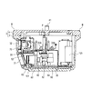
また、このとき、赤外線カメラ60の鏡胴63の外面は、熱電対102に当接(接触)して、熱電対102が設けられた板ばね101によって上方に付勢されることにより、熱電対102との接触状態が保持される(図8および図9参照)。上述のように、板ばね101の荷重はカメラユニット5の重量よりも軽いので、カメラユニット5をハウジング3に取り付けるときにカメラユニット5の自重が勝り、板ばね101の力でカメラユニット5が浮き上がることがない。したがって、本実施の形態によれば、蓋4を閉める前段階においてカメラユニット5をハウジング3に固定することができる。
カメラ装置1では、熱電対102による測定値がAD変換器103を通じて制御部に供給されることで、赤外線レンズ61の温度を測定(推定)し、かかる推定温度に基づく赤外線センサー62の出力値の補正を行うことができる。また、熱電対102により筐体2の内部温度が測定できるため、制御部により、上述したヒーターやファンを稼働させて筐体2内の温度を制御することもできる。本実施の形態によれば、上述のように、熱電対102が鏡胴63に直接接触する状態が保持されることにより、鏡胴63の温度を直に測定することができ、熱電対102による筐体2内の温度測定ひいては赤外線センサー62の出力値の補正を安定して行うことが可能になる。
続いて、カメラユニット5に対する必要なケーブルの取り付けが行われた後、図8および図9に示すように、ハウジング3に対して蓋4を閉めて、ボルトBが締結される。ここで、蓋4を閉める際に、プランジャーPが蓋4の内面に押圧されて下方に移動し、プランジャーPを付勢するばねが圧縮され、カメラユニット5をハウジング3に押さえつける力が発生し、カメラベース50ひいてはカメラユニット5全体を下方に付勢する。かかる作用により、筐体2に対するカメラユニット5の上下方向における位置が固定され、上下方向の移動や位置ずれが防止される。したがって、本実施の形態によれば、カメラユニット5をハウジング3に取り付ける際に、ねじ等の締結具を使用することなくハウジング3にしっかりと固定することが可能となる。
他方、交換作業時にカメラユニット5を筐体2から取り外す際には、この逆の手順、すなわち、各ボルトBを緩めてハウジング3に対して蓋4を開け、適宜ケーブルの取り外しを行い、カメラユニット5の取手511,512を持ってそのまま上方に引き上げればよい。
上述のように、本実施の形態では、ハウジング3の底部に板ばね101を介して熱電対102が設けられ、かかる熱電対102の上に赤外線カメラ60の鏡胴63が接触する構造であり、また、熱電対102のケーブル102cは、カメラユニット5を収納するスペースSを回避(迂回)するように配線されている(図5A等参照)。このため、カメラユニット5の着脱時に、板ばね101,熱電対102,および熱電対102のケーブル102cとカメラユニット5が干渉することがなく、カメラユニット5の着脱を簡単に行うことができる。
このように、本実施の形態のカメラ装置1は、赤外線カメラ60、可視光カメラ70、信号処理部などを備えたカメラユニット5がハウジング3に着脱可能な構成とされ、フォーカスや視差などの光学系の調整を、カメラユニット5の交換に先立って工場等で行うことのできる構造を有している。
また、カメラ装置1は、2次元(前後左右)方向の位置決めおよび位置規制をハウジング3の位置決めピン801,802およびカメラユニット5の位置決め穴501,502で行い、蓋4でプランジャーPを加圧することによりカメラユニット5の上下方向の位置規制を行う。かかる構成により、赤外線カメラ60、可視光カメラ70等を備えたカメラユニット5を安全かつ簡単に着脱することが出来、カメラユニット5の装着時に3次元(3軸)の位置決めが高精度に実現されることから、交換作業時における光学的な調整が不要となる。
また、本実施の形態のカメラ装置1は、熱電対102などの、製品サイクルの中で耐久性の長い部品をカメラユニット5側に搭載せずに筐体2側に搭載しているので、カメラユニット5の交換時における結線作業を簡略化することが出来る。したがって、本実施の形態によれば、カメラユニット5の交換作業を、最小限の労力で行うことができる。
上述した実施の形態では、筐体2の内部の温度を検出する温度検出部として熱電対102を備えた構成について例示したが、かかる温度検出部は、他にも種々の温度センサーを使用することができ、例えば非接触式の温度センサーであってもよい。また、温度検出部は、上述の実施の形態では板ばね101の上面側に配置される構成としたが、板ばね101の下面側に配置される構成としてもよい。また、温度検出部が取り付けられ鏡胴63に接触する弾性体として、板ばね101に代えて例えばコイルばねなどの他の弾性体を用いてもよい。
その他、上記実施の形態は、何れも本発明を実施するにあたっての具体化の一例を示したものに過ぎず、これらによって本発明の技術的範囲が限定的に解釈されてはならないものである。すなわち、本発明はその要旨、またはその主要な特徴から逸脱することなく、様々な形で実施することができる。
2017年1月18日出願の特願2017-006616の日本出願に含まれる明細書、図面および要約書の開示内容は、全て本願に援用される。
1 カメラ装置
2 筐体
3 ハウジング
4 蓋
5 カメラユニット
30 床面
31 赤外窓
32 可視窓
33(33A~33D) 孔
41 把持部
50 カメラベース
51 カメラカバー(カバー部材)
51a,51b 開口(支持部)
51c,51d 開口
52 支柱部
53 フード
54 鏡胴固定部
55 中間ベース部材
56 フレーム
57 カメラ固定部
60 赤外線カメラ
61 赤外線レンズ
62 赤外線センサー
63 鏡胴
64 センサー固定台
65 台座部
70 可視光カメラ
80 基板
85 端子台
90 中継基板(信号処理部)
101 板ばね(弾性体)
102 熱電対
102c 熱電対のケーブル
103 AD変換器
501,502 位置決め穴
521,522 支柱
523 ナット(高さ調整部)
801,802 位置決めピン(突起部)
P プランジャー
S スペース
2 筐体
3 ハウジング
4 蓋
5 カメラユニット
30 床面
31 赤外窓
32 可視窓
33(33A~33D) 孔
41 把持部
50 カメラベース
51 カメラカバー(カバー部材)
51a,51b 開口(支持部)
51c,51d 開口
52 支柱部
53 フード
54 鏡胴固定部
55 中間ベース部材
56 フレーム
57 カメラ固定部
60 赤外線カメラ
61 赤外線レンズ
62 赤外線センサー
63 鏡胴
64 センサー固定台
65 台座部
70 可視光カメラ
80 基板
85 端子台
90 中継基板(信号処理部)
101 板ばね(弾性体)
102 熱電対
102c 熱電対のケーブル
103 AD変換器
501,502 位置決め穴
521,522 支柱
523 ナット(高さ調整部)
801,802 位置決めピン(突起部)
P プランジャー
S スペース
Claims (7)
- ハウジングと蓋とを有する筐体と、
赤外線カメラを搭載し前記筐体内に収納されるカメラユニットと、を備え、
前記赤外線カメラは、赤外線レンズおよび該赤外線レンズを保持する鏡胴と、前記赤外線レンズを通じて受光された赤外線を検知する赤外線センサーと、を有し、
前記ハウジングは、前記カメラユニットが収納される際の前記鏡胴と接触する位置に、前記筐体の内部の温度を検出する温度検出部を備えている、
カメラ装置。 - 前記ハウジングは、前記鏡胴に対向する位置に弾性体を備え、
前記温度検出部は、前記弾性体の上に設けられた熱電対であり、
前記カメラユニットが前記ハウジングに収納される際に、前記熱電対が前記鏡胴に接触し、前記弾性体が前記鏡胴を付勢する、
請求項1に記載のカメラ装置。 - 前記弾性体は、前記ハウジングに設けられた板ばねであり、
前記熱電対は、前記板ばねの上面に配置されている、
請求項2に記載のカメラ装置。 - 前記板ばねの荷重は、前記カメラユニットの重量よりも軽い、
請求項3に記載のカメラ装置。 - 前記熱電対のケーブルは、前記ハウジングにおける前記カメラユニットが収納されるスペースを回避して配置されている、
請求項2から4のいずれかに記載のカメラ装置。 - 前記熱電対は、前記鏡胴に接触している、
請求項2から5のいずれかに記載のカメラ装置。 - 赤外線レンズを保持する鏡胴を備えた赤外線カメラを搭載したカメラユニットがハウジングと蓋とを有する筐体に装脱自在なカメラ装置において、
前記ハウジングに設けられ前記鏡胴と接触する温度検出部によって、前記筐体の内部温度を測定する、
カメラ装置の温度測定方法。
Priority Applications (1)
| Application Number | Priority Date | Filing Date | Title |
|---|---|---|---|
| JP2018563210A JP6773134B2 (ja) | 2017-01-18 | 2017-12-11 | カメラ装置およびカメラ装置の温度測定方法 |
Applications Claiming Priority (2)
| Application Number | Priority Date | Filing Date | Title |
|---|---|---|---|
| JP2017006616 | 2017-01-18 | ||
| JP2017-006616 | 2017-03-30 |
Publications (1)
| Publication Number | Publication Date |
|---|---|
| WO2018135181A1 true WO2018135181A1 (ja) | 2018-07-26 |
Family
ID=62907937
Family Applications (1)
| Application Number | Title | Priority Date | Filing Date |
|---|---|---|---|
| PCT/JP2017/044381 Ceased WO2018135181A1 (ja) | 2017-01-18 | 2017-12-11 | カメラ装置およびカメラ装置の温度測定方法 |
Country Status (2)
| Country | Link |
|---|---|
| JP (1) | JP6773134B2 (ja) |
| WO (1) | WO2018135181A1 (ja) |
Cited By (1)
| Publication number | Priority date | Publication date | Assignee | Title |
|---|---|---|---|---|
| KR20210104482A (ko) * | 2020-02-17 | 2021-08-25 | 조은아 | 극저온용 카메라 어셈블리 |
Families Citing this family (1)
| Publication number | Priority date | Publication date | Assignee | Title |
|---|---|---|---|---|
| KR102945386B1 (ko) * | 2025-09-30 | 2026-04-01 | (주)아르게스마린 | 방폭형 영상장치 |
Citations (4)
| Publication number | Priority date | Publication date | Assignee | Title |
|---|---|---|---|---|
| JPH02272409A (ja) * | 1989-04-13 | 1990-11-07 | Mitsubishi Electric Corp | 赤外線撮像装置の焦点調節方式 |
| JPH08114736A (ja) * | 1994-10-13 | 1996-05-07 | Fuji Photo Film Co Ltd | 固定焦点カメラ |
| JP2003166902A (ja) * | 2001-12-03 | 2003-06-13 | Ricoh Co Ltd | 半導体レーザの特性測定装置 |
| JP2004200778A (ja) * | 2002-12-16 | 2004-07-15 | Fuji Photo Optical Co Ltd | テレビカメラシステム |
-
2017
- 2017-12-11 WO PCT/JP2017/044381 patent/WO2018135181A1/ja not_active Ceased
- 2017-12-11 JP JP2018563210A patent/JP6773134B2/ja active Active
Patent Citations (4)
| Publication number | Priority date | Publication date | Assignee | Title |
|---|---|---|---|---|
| JPH02272409A (ja) * | 1989-04-13 | 1990-11-07 | Mitsubishi Electric Corp | 赤外線撮像装置の焦点調節方式 |
| JPH08114736A (ja) * | 1994-10-13 | 1996-05-07 | Fuji Photo Film Co Ltd | 固定焦点カメラ |
| JP2003166902A (ja) * | 2001-12-03 | 2003-06-13 | Ricoh Co Ltd | 半導体レーザの特性測定装置 |
| JP2004200778A (ja) * | 2002-12-16 | 2004-07-15 | Fuji Photo Optical Co Ltd | テレビカメラシステム |
Cited By (2)
| Publication number | Priority date | Publication date | Assignee | Title |
|---|---|---|---|---|
| KR20210104482A (ko) * | 2020-02-17 | 2021-08-25 | 조은아 | 극저온용 카메라 어셈블리 |
| KR102344576B1 (ko) * | 2020-02-17 | 2021-12-28 | 조은아 | 극저온용 카메라 어셈블리 |
Also Published As
| Publication number | Publication date |
|---|---|
| JP6773134B2 (ja) | 2020-10-21 |
| JPWO2018135181A1 (ja) | 2019-11-07 |
Similar Documents
| Publication | Publication Date | Title |
|---|---|---|
| JP3133742U (ja) | 赤外線カメラ | |
| JP5494051B2 (ja) | 撮像装置 | |
| CN108760055B (zh) | 温度监控装置、具有该装置的外壳及相关安装方法 | |
| JP2019071656A (ja) | カメラ | |
| WO2014069251A1 (ja) | カメラモジュール | |
| JP2011139138A (ja) | 工業用小型電子撮像カメラ | |
| JP6846976B2 (ja) | カメラ装置及び重力補償方法 | |
| WO2018135181A1 (ja) | カメラ装置およびカメラ装置の温度測定方法 | |
| JP2011193339A (ja) | 撮像装置の組み立て方法および撮像装置 | |
| WO2018135179A1 (ja) | カメラ装置およびカメラユニットの取付方法 | |
| WO2018117106A1 (ja) | 試料観察装置 | |
| JP2011211366A (ja) | 撮像装置 | |
| DK2708018T3 (da) | Optisk optageindretning | |
| JP2011041202A (ja) | 監視カメラ装置 | |
| JP2015155826A (ja) | 2軸ジンバルの零点調整装置及び方法 | |
| JP4407577B2 (ja) | 撮像装置、この撮像装置のフォーカス調整方法 | |
| WO2012077252A1 (ja) | 撮像装置 | |
| JP2011102942A (ja) | ステレオカメラ | |
| JP2017198755A (ja) | 撮像装置 | |
| JP6582781B2 (ja) | レンズ固定構造、撮像装置及び作業指示システム | |
| WO2020213256A1 (ja) | 温度異常検出装置 | |
| JP2010286733A (ja) | 露光条件切替ユニットおよびカメラユニット | |
| KR102884716B1 (ko) | 카메라 모듈 및 카메라 모듈의 제어 방법 | |
| CN120194812A (zh) | 热图像摄像机 | |
| JP2017092768A (ja) | 撮像装置 |
Legal Events
| Date | Code | Title | Description |
|---|---|---|---|
| 121 | Ep: the epo has been informed by wipo that ep was designated in this application |
Ref document number: 17892356 Country of ref document: EP Kind code of ref document: A1 |
|
| ENP | Entry into the national phase |
Ref document number: 2018563210 Country of ref document: JP Kind code of ref document: A |
|
| NENP | Non-entry into the national phase |
Ref country code: DE |
|
| 122 | Ep: pct application non-entry in european phase |
Ref document number: 17892356 Country of ref document: EP Kind code of ref document: A1 |