WO2018131348A1 - 成分濃度検出システム - Google Patents
成分濃度検出システム Download PDFInfo
- Publication number
- WO2018131348A1 WO2018131348A1 PCT/JP2017/044119 JP2017044119W WO2018131348A1 WO 2018131348 A1 WO2018131348 A1 WO 2018131348A1 JP 2017044119 W JP2017044119 W JP 2017044119W WO 2018131348 A1 WO2018131348 A1 WO 2018131348A1
- Authority
- WO
- WIPO (PCT)
- Prior art keywords
- liquid
- component concentration
- light
- unit
- concentration detector
- Prior art date
- Legal status (The legal status is an assumption and is not a legal conclusion. Google has not performed a legal analysis and makes no representation as to the accuracy of the status listed.)
- Ceased
Links
Images



Classifications
-
- A—HUMAN NECESSITIES
- A61—MEDICAL OR VETERINARY SCIENCE; HYGIENE
- A61M—DEVICES FOR INTRODUCING MEDIA INTO, OR ONTO, THE BODY; DEVICES FOR TRANSDUCING BODY MEDIA OR FOR TAKING MEDIA FROM THE BODY; DEVICES FOR PRODUCING OR ENDING SLEEP OR STUPOR
- A61M1/00—Suction or pumping devices for medical purposes; Devices for carrying-off, for treatment of, or for carrying-over, body-liquids; Drainage systems
- A61M1/14—Dialysis systems; Artificial kidneys; Blood oxygenators ; Reciprocating systems for treatment of body fluids, e.g. single needle systems for hemofiltration or pheresis
- A61M1/16—Dialysis systems; Artificial kidneys; Blood oxygenators ; Reciprocating systems for treatment of body fluids, e.g. single needle systems for hemofiltration or pheresis with membranes
-
- A—HUMAN NECESSITIES
- A61—MEDICAL OR VETERINARY SCIENCE; HYGIENE
- A61M—DEVICES FOR INTRODUCING MEDIA INTO, OR ONTO, THE BODY; DEVICES FOR TRANSDUCING BODY MEDIA OR FOR TAKING MEDIA FROM THE BODY; DEVICES FOR PRODUCING OR ENDING SLEEP OR STUPOR
- A61M1/00—Suction or pumping devices for medical purposes; Devices for carrying-off, for treatment of, or for carrying-over, body-liquids; Drainage systems
- A61M1/14—Dialysis systems; Artificial kidneys; Blood oxygenators ; Reciprocating systems for treatment of body fluids, e.g. single needle systems for hemofiltration or pheresis
- A61M1/16—Dialysis systems; Artificial kidneys; Blood oxygenators ; Reciprocating systems for treatment of body fluids, e.g. single needle systems for hemofiltration or pheresis with membranes
- A61M1/1601—Control or regulation
- A61M1/1603—Regulation parameters
- A61M1/1605—Physical characteristics of the dialysate fluid
- A61M1/1609—Physical characteristics of the dialysate fluid after use, i.e. downstream of dialyser
-
- G—PHYSICS
- G01—MEASURING; TESTING
- G01N—INVESTIGATING OR ANALYSING MATERIALS BY DETERMINING THEIR CHEMICAL OR PHYSICAL PROPERTIES
- G01N21/00—Investigating or analysing materials by the use of optical means, i.e. using sub-millimetre waves, infrared, visible or ultraviolet light
- G01N21/01—Arrangements or apparatus for facilitating the optical investigation
- G01N21/03—Cuvette constructions
- G01N21/05—Flow-through cuvettes
-
- G—PHYSICS
- G01—MEASURING; TESTING
- G01N—INVESTIGATING OR ANALYSING MATERIALS BY DETERMINING THEIR CHEMICAL OR PHYSICAL PROPERTIES
- G01N21/00—Investigating or analysing materials by the use of optical means, i.e. using sub-millimetre waves, infrared, visible or ultraviolet light
- G01N21/17—Systems in which incident light is modified in accordance with the properties of the material investigated
- G01N21/25—Colour; Spectral properties, i.e. comparison of effect of material on the light at two or more different wavelengths or wavelength bands
- G01N21/31—Investigating relative effect of material at wavelengths characteristic of specific elements or molecules, e.g. atomic absorption spectrometry
- G01N21/33—Investigating relative effect of material at wavelengths characteristic of specific elements or molecules, e.g. atomic absorption spectrometry using ultraviolet light
-
- G—PHYSICS
- G01—MEASURING; TESTING
- G01N—INVESTIGATING OR ANALYSING MATERIALS BY DETERMINING THEIR CHEMICAL OR PHYSICAL PROPERTIES
- G01N21/00—Investigating or analysing materials by the use of optical means, i.e. using sub-millimetre waves, infrared, visible or ultraviolet light
- G01N21/17—Systems in which incident light is modified in accordance with the properties of the material investigated
- G01N21/59—Transmissivity
-
- G—PHYSICS
- G01—MEASURING; TESTING
- G01N—INVESTIGATING OR ANALYSING MATERIALS BY DETERMINING THEIR CHEMICAL OR PHYSICAL PROPERTIES
- G01N21/00—Investigating or analysing materials by the use of optical means, i.e. using sub-millimetre waves, infrared, visible or ultraviolet light
- G01N21/84—Systems specially adapted for particular applications
- G01N21/85—Investigating moving fluids or granular solids
-
- A—HUMAN NECESSITIES
- A61—MEDICAL OR VETERINARY SCIENCE; HYGIENE
- A61M—DEVICES FOR INTRODUCING MEDIA INTO, OR ONTO, THE BODY; DEVICES FOR TRANSDUCING BODY MEDIA OR FOR TAKING MEDIA FROM THE BODY; DEVICES FOR PRODUCING OR ENDING SLEEP OR STUPOR
- A61M2205/00—General characteristics of the apparatus
- A61M2205/33—Controlling, regulating or measuring
- A61M2205/3306—Optical measuring means
- A61M2205/3313—Optical measuring means used specific wavelengths
Definitions
- the present invention relates to a system for irradiating a liquid with light and measuring the concentration of the component in the liquid from the degree of absorption, and more particularly to a component concentration detection system capable of measuring the albumin concentration.
- this hemodialysis apparatus is provided with a dialyzer 100 that is a blood purification apparatus in a blood circulation path, and a dialysate circuit that supplies dialysate to the dialyzer 100.
- the blood collected from the patient undergoes extracorporeal circulation that is returned to the body via the dialyzer 100, and the dialysis supplied to the dialyzer 100 via the semipermeable membrane of the dialyzer 100 during the extracorporeal circulation.
- the liquid is used to remove waste products and excess water from the blood as drainage.
- the hemodialysis apparatus is provided with a component concentration detection system 101, and the state of the patient during dialysis can be grasped by measuring a predetermined component concentration of the drainage from the dialyzer 100. That is, by measuring the concentration of urea, uric acid, and the like, which are waste products in the circulated effluent, the dialysis state of the patient during dialysis can be grasped in real time.
- the component concentration detection system 101 includes a component concentration detector 102 connected to the drainage flow path from the dialyzer 100 and a monitoring device 103 (analyzer) connected to the component concentration detector 102. And is formed.
- This component concentration detector 102 is formed so as to measure the concentration change by detecting the absorbance of the drainage from the dialyzer 100. That is, by irradiating light (for example, UV light) to the liquid cell part that circulates the drainage liquid (also simply referred to as liquid), and detecting the light after being absorbed by the liquid that circulates through the liquid cell part, The concentration of the liquid can be detected. Then, the detection result detected by the component concentration detector 102 is monitored by the monitoring device 103 so that the dialysis state can be grasped in real time.
- light for example, UV light
- the drainage contains albumin which is one index of the nutritional status of the patient, and by measuring the albumin concentration, while monitoring the dialysis status, the functional status of the liver, kidney, and Nutritional status (referred to as health status) can also be grasped.
- the concentration of albumin is measured by a dye binding method which is performed by utilizing a change in color tone due to the binding between albumin and a specific dye. That is, after removing a part of the effluent and allowing albumin to absorb a predetermined dye, the albumin concentration is measured by quantifying from the absorption wavelength of the dye (BCG method, BCP method, etc.). Therefore, real-time detection by the component concentration detector 102 is difficult, and there is a problem that it is very difficult to grasp the dialysis state and the health state with the common component concentration detection system 101.
- the present invention has been made in view of the above problems, and provides a component concentration detection system capable of detecting albumin concentration with a common liquid feeding circuit at the same time while detecting the component concentration of the liquid to be fed. It is intended to provide.
- a component concentration detection system of the present invention is provided in a flow path through which a liquid whose component concentration is to be detected flows, and irradiates the liquid with light to determine the degree of light absorption in the liquid.
- a first component concentration detector that detects a component concentration; a retention portion that retains the liquid flowing in the flow path; and the liquid that is retained in the retention portion is irradiated with light, and the degree of light absorption in the liquid
- a second component concentration detector for detecting the component concentration.
- the albumin concentration can be detected by the second component concentration detector. That is, a staying part is provided in the liquid feeding circuit, and a second component concentration detector is attached to the staying part. Then, light (for example, UV light) from the second component concentration detector is irradiated to the liquid (drainage from the dialyzer) that stays in the retention part, so that albumin in the liquid is denatured by light, and this irradiated light Can be detected to detect the albumin concentration in the retention portion. Therefore, the concentration of urea, uric acid, etc. is measured by the first component concentration detector to grasp the dialysis state, and at the same time, the albumin concentration is detected by the second component concentration detector in the common liquid feeding circuit. The health status can be grasped.
- light for example, UV light
- the staying part is formed by a branch channel branched from the channel through which the liquid is fed and a valve provided in the branch channel, and the second component concentration detector is The component concentration of the liquid staying in the branch channel may be detected.
- the retention portion is formed in the branch flow path by closing the valve of the branch flow path, and the concentration of albumin is detected by providing the second component concentration detector in the retention section.
- the concentration of urea, uric acid, etc. and the albumin concentration can be detected simultaneously with an easy configuration.
- the first and second component concentration detectors are disposed between an irradiation unit that emits light, a light receiving unit that receives light emitted from the irradiation unit, and the irradiation unit and the light receiving unit.
- a liquid cell part through which the liquid flows, and the liquid cell part may be formed of a cylindrical tube.
- the component concentration detector can be configured at low cost by using a cylindrical tube for the liquid cell portion of the component concentration detector, the cost of the entire system can be reduced.
- the liquid is a drainage discharged from the blood purification device, and the wavelength of light irradiated on the drainage is 240 to 260 nm.
- the component concentration detection system of the present invention it is possible to detect the concentration of albumin with a common liquid feeding circuit at the same time while detecting the component concentration of the liquid to be fed.
- FIG. 1 is a route diagram showing a hemodialysis apparatus to which a component concentration detection system of the present invention is applied. It is a figure which shows a component density
- FIG. 4 is a sectional view taken along line AA in FIG. 3. It is a figure which shows a coupling part. It is a figure which shows the path
- FIG. 1 is a route diagram showing a hemodialysis apparatus using a component concentration detector according to an embodiment of the present invention.
- the hemodialysis apparatus 1 includes a blood circulation path unit 2 that circulates a patient's blood extracorporeally, a dialyzer 3 that is provided in the middle of the blood circulation path unit 2, and discharges from the dialyzer 3.
- a drainage line 52 (drainage flow path) for discharging a liquid (also referred to as liquid) and a supply line 51 (supply flow path) for supplying dialysate to the dialyzer 3 are provided.
- the blood circulation path part 2 is formed of a flexible tube, and has an outward path part 21 for circulating the blood collected from the patient and a return path part 22 for returning the purified blood to the patient.
- These forward path section 21 and return path section 22 connect the patient and the dialyzer 3, and blood collected from the patient passes through the dialyzer 3 through the forward path section 21 by driving a pump (not shown). The blood purified by the dialyzer 3 returns to the patient through the return path section 22.
- the dialyzer 3 purifies the supplied blood and gradually waters, and has an inlet port 31 and an outlet port 32. That is, when the forward path portion 21 is connected to the inlet port 31 and the backward route portion 22 is connected to the outlet port 32, the patient's blood is supplied to the dialyzer 3 through the inlet port 31 and purified by the dialyzer 3. Blood is returned to the patient through outlet port 32.
- a plurality of hollow fibers are accommodated in a container body 33, and blood passes through the hollow fibers.
- the hollow fiber has a small through hole, and when blood passes through the hollow fiber, waste and excess water are permeated into the dialysate filled in the container body 33 through the through hole so that the blood is purified. It has become.
- the supply line 51 and the drainage line 52 are formed of flexible tubes, and are connected to the dialyzer 3, respectively.
- the dialyzer 3 has a supply port 34 to which the dialysate is supplied and a drain port 35 for discharging the dialysate, and the supply line 51 is connected to the supply port 34 and discharged.
- the liquid line 52 and the drainage port 35 are connected. Accordingly, the dialysate is supplied from the dialysate supply source (not shown) to the dialyzer 3 through the supply line 51, dialyzed in the container body 33 of the dialyzer 3, and then used through the drainage line 52.
- the dialysate is discharged as drainage (liquid of the present invention).
- a component concentration detection system 6 is provided in the drainage line 52. This component concentration detection system 6 is for grasping the state of the patient during dialysis by measuring the component concentration of the drainage discharged from the dialyzer 3.
- the component concentration detection system 6 includes a first component concentration detector 4a that detects a predetermined concentration in blood circulating outside the body, a retention portion that retains the liquid flowing in the drainage line, and a second portion provided in the retention portion. Component concentration detector 4b.
- the drainage line 52 has a main channel 52a directly connected to the drainage port 35 and a branch channel 52b branched from the main channel 52a.
- the main channel 52a includes a first component.
- a concentration detector 4a is provided, and a second component concentration detector 4b is provided in the branch flow path 52b.
- the branch channel 52b is provided with a valve 54.
- the valve 54 By opening and closing the valve 54, the liquid in the branch channel 52b can be circulated. That is, when the valve 54 is opened, the liquid flows from the main flow path 52a into the branch flow path 52b, and the liquid can flow through the branch flow path 52b. Further, by closing the valve 54, the flow of the liquid flowing through the branch flow path 52b is stopped, and the liquid can be retained in the branch flow path 52b. In other words, the retention portion 56 (see FIG. 7) is formed in the branch flow path 52b by closing the valve 54.
- a second component concentration detector 4 b is provided upstream of the staying portion 56, that is, the valve 54.
- the first component concentration detector 4a and the second component concentration detector 4b are formed in the same configuration. Therefore, the description of the first component concentration detector 4a and the second component concentration detector 4b will be made in common, and the first component concentration detector 4a and the second component concentration detector 4b will be described. When it is not necessary to distinguish between them, they are simply called the component concentration detector 4.
- the component concentration detector 4 is for detecting the component concentration of the liquid flowing through the drainage line 52 in real time. This component concentration detector 4 irradiates the liquid flowing through the drainage line 52 with light, and detects the component concentration in the liquid from the light absorption degree of the light.
- the component concentration detector 4 of this embodiment is connected to the monitoring device M, and the monitoring device M monitors the detection result detected by the component concentration detector 4 and adjusts various settings of the component concentration detector 4. It has become so.
- the component concentration detector 4 has a cell unit portion 7, a lamp unit portion 8, and a drainage monitor portion 9 in a housing portion 43 having an inlet portion 41 and an outlet portion 42.
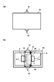
- FIG. 2A is a diagram showing an appearance of the component concentration detector 4
- FIG. 2B is a diagram showing a state in which the cover part of the housing part 43 is removed.
- the housing part 43 is a box-shaped case member.
- the cell unit part 7 is accommodated in the central part thereof, and the lamp unit part 8 and the drainage monitor part 9 are accommodated so as to sandwich the cell unit part 7. ing. That is, the liquid flowing through the cell unit 7 is irradiated with UV light from the lamp unit 8, and the UV light that has passed through the liquid is received by the drainage monitor unit 9 so that the component concentration in the liquid is detected. It has become.
- the cell unit portion 7 circulates the liquid in the drainage line 52 and includes an inlet portion 41 and an outlet portion 42 connected to the drainage line 52. That is, the inlet 41 is connected to the upstream side of the drainage line 52 and the outlet 42 is connected to the downstream side of the drainage line 52, so that the liquid discharged from the dialyzer 3 passes through the inlet 41. 7 and flows from the outlet 42 to the drainage line 52 again.
- the first component concentration detector 4a is connected to the inlet 41 and the upstream side of the main channel 52a, is connected to the outlet 42 and the downstream side of the main channel 52a, and the second component concentration detector 4a
- the component concentration detector 4b is connected to the inlet 41 and the upstream side of the branch channel 52b, and is connected to the outlet 42 and the downstream side of the branch channel 52b.
- the cell unit section 7 includes a liquid cell section 71 through which a liquid flows and a cell frame body section 72 that supports the liquid cell section 71.
- the cell frame 72 has a main body 72a that extends linearly, and support portions 72b that extend from both ends of the main body 72a in directions orthogonal to each other. It has a so-called U-shaped cross section.
- Both support portions 72b are portions that support the liquid cell portion 71, and support both end portions of the liquid cell portion 71 extending in one direction. That is, the support portion 72b can support the liquid cell portion 71 at a position away from the main body portion 72a by a predetermined distance.
- the liquid cell portion 71 When the cell unit portion 7 is accommodated in the housing portion 43, the liquid cell portion 71 is It is disposed between the lamp unit unit 8 and the drainage monitor unit 9 and is supported so that the liquid cell unit 71 is included in the irradiation region of the UV light from the lamp unit unit 8.
- the cell unit portion 7 is detachably formed with respect to the housing portion 43.
- the cell frame 72 can be attached to and detached from the housing 43. That is, the cell frame 72 can be fastened with the screw 73.
- the cell frame 72 is removed as shown in FIG.
- the cell frame portion 72 is arranged between the lamp unit portion 8 and the drainage monitor portion 9 and fastened with a screw 73 to be fixed to the housing portion 43.
- a notch 44 is formed in the housing 43, and the end of the main body 72 a of the cell frame 72 is very small in the notch 44 when the cell frame 72 is arranged. It fits in a state having a gap.
- the cell frame body portion 72 is positioned and fixed with respect to the housing portion 43 by fastening the screw 73 while pressing against the cutout portion 44 side. That is, in the state where the cell frame body part 72 is positioned in the housing part 43, as described above, the liquid cell part 71 is held in a state included in the irradiation region of the UV light from the lamp unit part 8, and the liquid cell part The axial direction of 71 and the axial direction of the lamp unit 8 (cold cathode tube UV lamp 81a) are fixed in parallel. Thereby, even when the cell frame body part 72 is removed, it is possible to easily return to the arrangement state of the liquid cell part 71 before the attachment / detachment by simply attaching the cell frame body part 72 to the housing part 43. .
- the lamp unit unit 8 irradiates the liquid cell unit 71 with light.
- the lamp unit portion 8 is provided at a position adjacent to the cell unit portion 7.
- the lamp unit 8 is provided with an irradiation unit 81, and in this embodiment, a cold cathode tube UV lamp 81a is provided.
- the cold-cathode tube UV lamp 81a is supported by a lamp support 82, and the cold-cathode tube UV lamp 81a extends in the direction (axis).
- Direction is fixed along the direction (axial direction) in which the liquid cell portion 71 extends.
- the cold-cathode tube UV lamp 81 a is fixed by the lamp support 82 at both ends thereof, and is supported so as to cover the portion that irradiates light with the curved portion 83.
- An opening 84 is formed in the portion of the lamp support portion 72b facing the liquid cell portion 71 so that light from the cold cathode tube UV lamp 81a (irradiation portion 81) is irradiated from the opening 84. It has become. That is, the cold-cathode tube UV lamp 81a is irradiated with light over the entire surface of the cylindrical tube, but the light irradiated from the portion not facing the opening 84 is reflected by the curved portion 83 and the opening. By irradiating from 84, the light irradiated from the cold-cathode tube UV lamp 81a is efficiently irradiated to the liquid cell unit 71.
- a drainage monitor unit 9 is provided at a position facing the lamp unit unit 8 across the liquid cell unit 71.
- the drainage monitor unit 9 receives light emitted from the cold cathode tube UV lamp 81a and passed through the liquid cell unit 71.
- the drainage monitor unit 9 is provided with a light receiving unit 91, and the light receiving unit 91 is provided with a photodiode.
- the light receiving unit 91 is disposed on an extension of the irradiation direction of the cold cathode tube UV lamp 81a.
- the center of the cold cathode tube UV lamp 81a, the center of the liquid cell unit 71, a photodiode (light receiving unit). 91) are arranged at positions where the centers thereof are aligned.
- the light-receiving surface of the light-receiving part 91 is formed so as to face along the irradiation range in the longitudinal direction of the cold cathode tube UV lamp 81a. Thereby, the light received from the cold cathode tube UV lamp 81a and passed through the liquid cell part 71 can be received by the light receiving part 91 without waste.
- the lamp unit 8 described above is also provided with a light receiving part (referred to as a second light receiving part 85).
- the second light receiving unit 85 monitors the light output state of the cold cathode tube UV lamp 81 a of the lamp unit 8.
- a second opening 86 is formed on the opposite side of the lamp support 72 b from the opening 84, and the second light receiving unit 85 is provided so as to face the second opening 86. It has been. As a result, the light from the cold-cathode tube UV lamp 81 a that is the irradiation unit 81 is directly received by the second light receiving unit 85.
- the second light receiving part is attached to the housing part 43 side, and the electrical wiring connected to the second light receiving part does not hinder operability when the cell frame part 72 is removed. It is like that.
- the light quantity value received by the second light receiving unit 85 is used as a reference value for the cold cathode tube UV lamp 81a. That is, the light emitted from the cold-cathode tube UV lamp 81a passes through the liquid that passes through the liquid cell unit 71 and is received by the light receiving unit 91, so that the component concentration is detected from the amount of light absorbed in the liquid.
- the amount of light absorbed by the liquid is accurately determined based on the amount of light received by the second light receiving unit 85. Can be calculated well.
- the lifetime of the cold cathode tube UV lamp 81a can also be monitored by providing a threshold value for the light quantity value obtained from the second light receiving unit 85.
- a cylindrical tube is used for the liquid cell portion 71 through which the liquid flows.
- the liquid cell portion 71 has a shape extending in one direction, and both end portions are supported by the support portions 72 b of the cell frame body portion 72. That is, the cylindrical tube is supported in a state in which the extending direction of the cylindrical tube coincides with the extending direction of the cold cathode tube UV lamp 81a, and the light irradiation direction (the direction irradiated from the irradiation unit 81 to the light receiving unit 91).
- the cylindrical tube is supported in a state orthogonal to the axial direction of the cylindrical tube. That is, the cylindrical tube is supported in a state where the outer peripheral surface of the cylindrical tube faces the light source of the irradiation unit 81.
- This cylindrical tube is made of quartz. That is, if a resin tube or the like is used for the liquid cell portion 71, the UV light of the cold cathode tube UV lamp 81a is absorbed by the resin tube, so the amount of light received by the light receiving portion 91 is an error corresponding to the amount absorbed by the resin tube. However, by using quartz, the UV light of the cold cathode tube UV lamp 81a used in the irradiation unit 81 is suppressed as much as possible from being absorbed by the liquid cell unit 71, and the liquid flowing in the cylindrical tube is reduced. The amount of light absorbed can be detected with high accuracy.
- a light collecting unit 10 that collects light that has passed through the liquid is provided between the liquid flowing through the liquid cell unit 71 and the light receiving unit 91.
- the liquid cell unit 71 and the light collecting unit 10 are provided integrally. That is, in this embodiment, since the cylindrical tube is provided in the liquid cell unit 71, the outer peripheral surface of the cylindrical tube serves as a lens (condensing unit 10), and collects light that has passed through the liquid to receive light.
- the part 91 can be irradiated. Specifically, as shown in FIG.
- the light irradiated from the irradiation unit 81 is refracted by the curved outer peripheral surface 71 a forming the cylindrical tube, and passes through the liquid in the cylindrical tube of the liquid cell unit 71. Thereafter, the light is condensed and travels closer to the center of the irradiated light than immediately after passing through the liquid.
- the light receiving unit 91 amplifies the received light intensity as compared with the case where there is no light collecting effect, so that the wavelength band absorbed by the liquid clearly appears, and the liquid component concentration detection accuracy can be improved.
- FIG. 6 shows the light of the case where the condensing part 10 is not used (when a parallel plate (liquid cell part formed in a plane perpendicular to the irradiation direction) is used instead of the cylindrical tube). It shows the course. In this case, since the light travels with the spread of the light emitted from the irradiation unit 81, the light receiving unit 91 cannot receive the light and loses the amount of light, which may reduce the liquid component concentration detection accuracy.
- the liquid cell part 71 is connected to the inlet part 41 and the outlet part 42.
- the inlet portion 41 and the outlet portion 42 have the same structure. Specifically, as shown in FIG. 5, the inlet portion 41 seals the joint portion 45 that covers the cylindrical tube (liquid cell portion 71) protruding from the housing portion 43, and the gap between the joint portion 45 and the cylindrical tube.
- the seal member 46 is formed.
- the joint 45 is connected to the upstream drain line 52 (the main flow path 52a in the first component concentration detector 4a and the branch flow path 52b in the second component concentration detector 4b). And a joint opening 45b connected to the liquid cell part 71, and the flange part 45c is fixed by being fastened to the housing part 43 with screws 45d.
- the joint opening 45b is formed in a tapered shape that becomes narrower toward the pipe connecting portion 45a.
- the seal member 46 is pressed and fixed. That is, in the liquid cell portion 71 (cylindrical tube) protruding from the housing portion 43, the first collar 47, the seal member 46 (O-ring), and the second collar 48 are disposed in this order from the housing portion 43 side.
- the joint opening 45b is fitted and fixed. That is, when the joint portion 45 is screwed to the housing portion 43, the joint portion 45 is further fastened with the screw 45d after the taper portion of the joint opening 45b comes into contact with the seal member 46. Is pressed.
- the seal member 46 pressed by the tapered portion expands and comes into close contact with the cylindrical tube and the tapered portion to form a cylinder.
- the tube and the joint portion 45 are sealed. That is, the liquid that has entered the pipe connection part 45a from the drain line 52 flows into the cylindrical pipe without leaking from the joint opening 45b, and flows out from the outlet part 42 to the drain line 52 again.
- the joint portion 45 With such a configuration of the joint portion 45, it can be used as the liquid cell portion 71 without any processing into a cylindrical tube, and has a cheaper configuration than the conventional liquid cell portion 71 having a complicated configuration. can do.
- the UV light irradiated from the irradiation unit 81 to the liquid flowing in the main channel 52a passes through the cylindrical tube of the liquid cell unit 71.
- the concentrations of urea, uric acid and the like, which are waste products in the liquid are measured, and the dialysis state of the patient during dialysis can be grasped in real time.
- the second component concentration detector 4b provided in the branch channel 52b can detect the albumin concentration. That is, when the valve 54 of the branch flow path 52b is closed with the liquid flowing through the drain line 52 and the concentration measured in real time by the first component concentration detector 4a, the branch flow path 52b Liquid stays. That is, as shown in FIG. 7, when the valve 54 of the branch flow path 52b is closed, the liquid flowing through the branch flow path 52b loses its place and stays in the branch flow path 52b (the retention portion 56 is formed). As a result, the liquid flowing through the liquid cell part 71 of the second component concentration detector 4b connected to the branch flow path 52b also stays in the liquid cell part 71.
- UV light (in this embodiment, the wavelength is set to 240 to 260 nm) is irradiated from the irradiation unit 81 of the second component concentration detector 4b
- the albumin in the liquid cell unit 71 is denatured with time.
- the liquid in the liquid cell unit 71 becomes cloudy. That is, the light applied to the liquid cell unit 71 is received by the light receiving unit 91, but the amount of received light changes due to the cloudy liquid. And since the cloudiness state will also change if the amount of albumin in a liquid changes, an albumin density
- the concentration of urea, uric acid, etc. is measured by the first component concentration detector 4a to grasp the dialysis state, and at the same time, the albumin concentration is detected by the second component concentration detector 4b in the common liquid feeding circuit.
- the health status of patients undergoing dialysis can be grasped at the same time.
- the branch flow path 52b is provided on the downstream side of the first component concentration detector 4a and the second component concentration detector 4b is arranged has been described.
- the first component concentration detector 4a is described.
- the second component concentration detector 4b may be disposed by providing a branch flow path 52b on the upstream side. Even in this configuration, the albumin concentration can be measured by the second component concentration detector 4b by retaining the liquid in the branch channel 52b.
- the example in which the UV light irradiated from the irradiation unit 81 is set to a wavelength of 240 to 260 nm has been described.
- albumin is denatured as a result of irradiation of the staying liquid, You may use the light of another wavelength.
- the said embodiment demonstrated the example in which the condensing part 10 was integrated with the liquid cell part 71, between the liquid cell part 71 and the drainage monitor part 9, light is made into a fixed area
- a member capable of condensing light may be arranged as the light collecting unit 10. Even in this case, the light that has passed through the liquid cell unit 71 is condensed in a certain region and received by the light receiving unit 91, so that the light receiving intensity at the light receiving unit 91 is increased, thereby improving the liquid component concentration detection accuracy. it can.
- a quartz cylindrical tube is used for the liquid cell portion 71, but the cylindrical tube may be formed of other members. That is, in the above-described embodiment, since the UV light is irradiated, quartz is used as an example, which absorbs very little UV light. It is preferable in that the absorption of light by a member other than the liquid flowing through the liquid cell portion 71 is suppressed, and the density detection accuracy can be improved.
- the liquid cell part 71 formed by the parallel plate orthogonal to the light from the irradiation part 81 ( It may be a liquid cell portion formed in a plane perpendicular to the irradiation direction.
- the liquid cell unit 71 is provided on the cell frame body 72 and the cell frame body 72 is detachable.
- the liquid cell unit 71 is directly integrated with the housing unit 43. It may be fixed.
Landscapes
- Health & Medical Sciences (AREA)
- Physics & Mathematics (AREA)
- Life Sciences & Earth Sciences (AREA)
- General Health & Medical Sciences (AREA)
- Chemical & Material Sciences (AREA)
- Analytical Chemistry (AREA)
- Biochemistry (AREA)
- General Physics & Mathematics (AREA)
- Immunology (AREA)
- Pathology (AREA)
- Heart & Thoracic Surgery (AREA)
- Spectroscopy & Molecular Physics (AREA)
- Urology & Nephrology (AREA)
- Hematology (AREA)
- Engineering & Computer Science (AREA)
- Anesthesiology (AREA)
- Biomedical Technology (AREA)
- Emergency Medicine (AREA)
- Animal Behavior & Ethology (AREA)
- Public Health (AREA)
- Veterinary Medicine (AREA)
- Vascular Medicine (AREA)
- Investigating Or Analysing Materials By Optical Means (AREA)
- External Artificial Organs (AREA)
- Optical Measuring Cells (AREA)
Abstract
送液される液体の成分濃度を検出しつつ、同時に共通の送液回路でアルブミン濃度も検出することができる成分濃度検出システムを提供する。具体的には、成分濃度を検出される対象となる液体が流れる流路に設けられ、前記液体に光を照射してその光吸収度合いから液体中の成分濃度を検出する第1の成分濃度検出器と、前記流路を流れる液体を滞留させる滞留部と、前記滞留部で滞留される前記液体に光を照射してその光吸収度合いから液体中の成分濃度を検出する第2の成分濃度検出器と、を備える構成とする。
Description
本発明は、液体に光を照射してその吸光度合いから液体内の成分濃度を測定するシステムに関するものであり、特に、アルブミン濃度を測定できる成分濃度検出システムに関するものである。
腎不全の患者に対し、腎臓機能を人工的に代替する血液透析装置を用いて血液透析療法による治療が行われている。この血液透析装置は、図8に示すように、血液循環経路に血液浄化装置であるダイアライザ100が設けられており、このダイアライザ100に透析液を供給する透析液回路が設けられている。そして、患者から採取された血液はダイアライザ100を経由して体内に戻される体外循環が行われ、体外循環が行われている間にダイアライザ100の半透膜を介してダイアライザ100に供給された透析液により血液中の老廃物、及び、余剰水分が排液として除去されるようになっている。
また、血液透析装置には、成分濃度検出システム101が設けられており、ダイアライザ100からの排液の所定の成分濃度を計測することより透析中の患者の状態を把握することができる。すなわち、流通する排液中の老廃物である尿素、尿酸等の濃度を計測することにより、透析中の患者の透析状態をリアルタイムで把握することができる。
この成分濃度検出システム101は、図8に示すように、ダイアライザ100からの排液流路に接続される成分濃度検出器102と、成分濃度検出器102に接続される監視装置103(分析装置)とで形成されている。この成分濃度検出器102は、ダイアライザ100からの排液に対する吸光度を検出することで濃度変化を計測できるように形成されている。すなわち、排液(単に液体とも言う)を流通させる液体セル部に光(例えばUV光)を照射し、液体セル部を流通する液体により吸収された後の光を受光部で検出することにより、液体の濃度を検出することができる。そして、成分濃度検出器102で検出した検出結果が監視装置103にモニタリングされることにより、リアルタイムで透析状態を把握できるようになっている。
ここで、排液中には患者の栄養状態の1つの指標であるアルブミンが含まれており、このアルブミン濃度を測定することにより、透析状態を監視しつつ、肝臓、腎臓の機能状態、及び、栄養状態等(健康状態と称す)も把握することができる。通常、アルブミン濃度の測定は、アルブミンと特定の色素との結合による色調の変化を利用して行われる色素結合法が用いられる。すなわち、排液の一部を取り出してアルブミンに所定の色素を吸収させた後、色素の吸収波長から定量化することにより、アルブミン濃度が測定される(BCG法、BCP法等)。したがって、上記成分濃度検出器102によるリアルタイムでの検出は困難であり、共通の成分濃度検出システム101で透析状態と健康状態を把握することは非常に困難であるという問題があった。
本発明は、上記の問題点に鑑みてなされたものであり、送液される液体の成分濃度を検出しつつ、同時に共通の送液回路でアルブミン濃度も検出することができる成分濃度検出システムを提供することを目的としている。
上記課題を解決するために本発明の成分濃度検出システムは、成分濃度を検出される対象となる液体が流れる流路に設けられ、前記液体に光を照射してその光吸収度合いから液体中の成分濃度を検出する第1の成分濃度検出器と、前記流路を流れる液体を滞留させる滞留部と、前記滞留部で滞留される前記液体に光を照射してその光吸収度合いから液体中の成分濃度を検出する第2の成分濃度検出器と、を備えることを特徴としている。
上記成分濃度検出システムによれば、第2の成分濃度検出器によりアルブミン濃度を検出することができる。すなわち、送液回路内には、滞留部が設けられており、この滞留部に第2の成分濃度検出器が取り付けられている。そして、滞留部に滞留する液体(ダイアライザからの排液)に第2の成分濃度検出器による光(例えばUV光)が照射されることにより液体中のアルブミンが光によって変性し、この照射した光を受光することにより滞留部におけるアルブミン濃度を検出することができる。したがって、第1の成分濃度検出器により尿素、尿酸等の濃度を計測して透析状態を把握し、それと同時に共通の送液回路内で、第2の成分濃度検出器によりアルブミン濃度を検出して健康状態を把握することができる。
また、前記滞留部は、前記液体が送液される前記流路から分岐された分岐流路と、この分岐流路に設けられたバルブによって形成されており、前記第2の成分濃度検出器は、前記分岐流路に滞留する液体の成分濃度を検出する構成にしてもよい。
この構成によれば、分岐流路のバルブを閉じることによって分岐流路に滞留部を形成し、この滞留部に第2の成分濃度検出器を設けることにより、アルブミン濃度を検出し、分岐流路とは別の流路に第1の成分濃度検出器を設けることにより、容易な構成で尿素、尿酸等の濃度と、アルブミン濃度を同時に検出することができる。
また、前記第1及び第2の成分濃度検出器は、光を照射する照射部と、照射部から照射された光を受光する受光部と、前記照射部と前記受光部との間に配置され、前記液体が流通する液体セル部と、を有しており、前記液体セル部は、円筒管で形成されている構成にしてもよい。
この構成によれば、成分濃度検出器の液体セル部に円筒管を用いることにより、成分濃度検出器を安価に構成することができるため、システム全体のコストダウンを図ることができる。
また、上記成分濃度検出システムの具体的様態としては、前記液体は、血液浄化装置から排出された排液であり、この排液に照射される光の波長は240~260nmである。
本発明の成分濃度検出システムによれば、送液される液体の成分濃度を検出しつつ、同時に共通の送液回路でアルブミン濃度も検出することができる。
本発明の成分濃度検出システムに係る実施の形態を図面を用いて説明する。
図1は、本発明の一実施形態における成分濃度検出器を使用した血液透析装置を示す経路図である。
図1に示すように、血液透析装置1は、患者の血液を体外循環させる血液循環経路部2と、血液循環経路部2の途中に設けられ血液を浄化するダイアライザ3と、ダイアライザ3からの排液(液体ともいう)を排出する排液ライン52(排液流路)と、ダイアライザ3に透析液を供給する供給ライン51(供給流路)とを有している。
血液循環経路部2は、可撓性チューブで形成されており、患者から採取した血液を流通させる往路経路部21と、浄化された血液を患者に戻す復路経路部22とを有している。これら往路経路部21と復路経路部22は、患者とダイアライザ3とを連結するものであり、不図示のポンプを駆動させることにより、患者から採取された血液が往路経路部21を通じてダイアライザ3を通過し、ダイアライザ3で浄化された血液が復路経路部22を通じて患者に戻るようになっている。
ダイアライザ3は、供給された血液の浄化、及び、徐水を行うものであり、入口ポート31と出口ポート32を有している。すなわち、入口ポート31に往路経路部21が接続され、出口ポート32に復路経路部22が接続されることにより、患者の血液は、入口ポート31を通じてダイアライザ3に供給され、ダイアライザ3で浄化された血液は、出口ポート32を通じて患者に戻される。このダイアライザ3は、容器本体33に複数の中空糸が収容されており、中空糸内を血液が通過するようになっている。中空糸には、小さな貫通孔が形成されており、血液が中空糸を通過すると、その貫通孔を通じて容器本体33に充填される透析液に老廃物や余剰水分が透過され血液が浄化されるようになっている。
供給ライン51及び排液ライン52は、可撓性チューブで形成されており、それぞれダイアライザ3に接続されている。具体的には、ダイアライザ3には、透析液が供給される供給ポート34と、透析液を排液する排液ポート35とを有しており、供給ライン51が供給ポート34と接続され、排液ライン52と排液ポート35とが接続されている。したがって、透析液は、透析液の供給源(不図示)から供給ライン51を通じてダイアライザ3に供給され、ダイアライザ3の容器本体33内で透析処理が行われた後、排液ライン52を通じて使用後の透析液が排液(本発明の液体)として排出されるようになっている。
また、排液ライン52には、成分濃度検出システム6が設けられている。この成分濃度検出システム6は、ダイアライザ3から排出される排液の成分濃度を計測することにより、透析中の患者の状態を把握するためのものである。成分濃度検出システム6は、体外循環する血液中の所定の濃度を検出する第1の成分濃度検出器4aと、排液ラインに流れる液体を滞留させる滞留部と、この滞留部に設けられる第2の成分濃度検出器4bとを有している。
排液ライン52は、排液ポート35に直接接続されるメイン流路52aと、メイン流路52aから分岐される分岐流路52bとを有しており、メイン流路52aには第1の成分濃度検出器4aが設けられ、分岐流路52bには第2の成分濃度検出器4bが設けられている。そして、分岐流路52bには、バルブ54が設けられており、このバルブ54を開閉動作させることにより分岐流路52b内の液体を流通させることができる。すなわち、バルブ54を開状態にすると、メイン流路52aから液体が分岐流路52bに流れ込み、液体を分岐流路52bに流通させることができる。また、バルブ54を閉状態にすることにより、分岐流路52bを流通する液体の流れが停止され、分岐流路52b内に液体を滞留させることができる。すなわち、このバルブ54を閉状態にすることにより分岐流路52bに滞留部56(図7参照)が形成される。そして、この滞留部56、すなわち、バルブ54よりも上流側に第2の成分濃度検出器4bが設けられている。
ここで、本実施形態では、第1の成分濃度検出器4a及び第2の成分濃度検出器4bは同じ構成で形成されている。したがって、これら第1の成分濃度検出器4a及び第2の成分濃度検出器4bの説明は、共通して行うこととし、これら第1の成分濃度検出器4a及び第2の成分濃度検出器4bを区別して呼ぶ必要がない場合は、単に成分濃度検出器4と呼ぶことにする。
成分濃度検出器4は、排液ライン52を流れる液体の成分濃度をリアルタイムに検出するためのものである。この成分濃度検出器4は、排液ライン52に流れる液体に光を照射して、その光の光吸収度合いから液体内の成分濃度を検出するものである。本実施形態の成分濃度検出器4は、監視装置Mと接続されており、監視装置Mにより、成分濃度検出器4で検出した検出結果がモニタリングされ、成分濃度検出器4の各種設定が調節されるようになっている。
成分濃度検出器4は、図2に示すように、入口部41と出口部42を有するハウジング部43内にセルユニット部7と、ランプユニット部8と、排液モニタ部9とを有している。ここで、図2(a)は、成分濃度検出器4の外観を表した図であり、図2(b)は、ハウジング部43の蓋部を取り外した状態を示す図である。ハウジング部43は、箱状のケース部材であり、その中央部分にセルユニット部7が収容されており、そのセルユニット部7を挟むように、ランプユニット部8、排液モニタ部9が収容されている。すなわち、セルユニット部7に流れる液体にランプユニット部8からUV光が照射され、液体を通過したUV光を排液モニタ部9で受光することにより、液体内の成分濃度が検出されるようになっている。
セルユニット部7は、排液ライン52の液体を流通させるものであり、排液ライン52に接続される入口部41と出口部42とを備えている。すなわち、入口部41が排液ライン52の上流側と接続され、出口部42が排液ライン52の下流側に接続されることにより、ダイアライザ3から排出された液体は入口部41を通じてセルユニット部7を通過し、出口部42から再び排液ライン52に流れるようになっている。具体的には、第1の成分濃度検出器4aは、入口部41とメイン流路52aの上流側と接続され、出口部42とメイン流路52aの下流側に接続されており、第2の成分濃度検出器4bは、入口部41と分岐流路52bの上流側と接続され、出口部42と分岐流路52bの下流側に接続されている。
セルユニット部7は、液体が流通する液体セル部71と、この液体セル部71を支持するセル枠体部72とを有している。セル枠体部72は、図3(b)に示すように、直線状に伸びる本体部72aと、この本体部72aの両端部からそれぞれ直交する方向に伸びる支持部72bとを有しており、いわゆる断面コの字の形状を有している。そして、両支持部72bは、液体セル部71を支持する部分であり、一方向に伸びる液体セル部71の両端部を支持している。すなわち、支持部72bは、液体セル部71が本体部72aから所定距離離れた位置に支持できるようになっており、セルユニット部7がハウジング部43に収容された状態では、液体セル部71がランプユニット部8と排液モニタ部9との間に配置され、ランプユニット部8からのUV光の照射領域に液体セル部71が含まれる状態に支持されるようになっている。
セルユニット部7は、ハウジング部43に対して着脱自在に形成されている。具体的には、セル枠体部72がハウジング部43に対して着脱できるようになっている。すなわち、セル枠体部72は、ネジ73で締結できるようになっており、ネジ73を外すと、図3(a)に示すようにセル枠体部72が取り外され、図2(b)に示すように、セル枠体部72をランプユニット部8と排液モニタ部9との間に配置しネジ73で締結することにより、ハウジング部43に固定されるようになっている。具体的には、ハウジング部43には、切欠部44が形成されており、セル枠体部72を配置した状態では、セル枠体部72の本体部72aの端部が切欠部44に微少な隙間を有する状態で嵌まり合うようになっている。この状態から、切欠部44側に押し当てつつネジ73を締結することにより、セル枠体部72がハウジング部43に対して位置決めされて固定されるようになっている。すなわち、セル枠体部72がハウジング部43に位置決めされた状態では、上述のように、液体セル部71がランプユニット部8からのUV光の照射領域に含まれる状態に保持され、液体セル部71の軸方向と、ランプユニット部8(冷陰極管UVランプ81a)の軸方向とが平行になるように固定される。これにより、セル枠体部72を取り外した場合でも、セル枠体部72をハウジング部43に取り付けるだけで、着脱前の液体セル部71の配置状態に容易に戻すことができるようになっている。
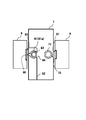
ランプユニット部8は、液体セル部71に光を照射するものである。ランプユニット部8は、本実施形態では、セルユニット部7に隣接する位置に設けられている。ランプユニット部8は、照射部81が設けられており、本実施形態では、冷陰極管UVランプ81aが設けられている。具体的には、冷陰極管UVランプ81aは、図3(a)、図4に示すように、ランプ支持体82に支持されて設けられており、冷陰極管UVランプ81aの伸びる方向(軸方向)が、液体セル部71の伸びる方向(軸方向)に沿うように固定されている。すなわち、冷陰極管UVランプ81aは、ランプ支持体82により、その両端部で固定され、光を照射する部分を湾曲部83で覆うように支持されている。そして、ランプ支持部72bの液体セル部71と対向する部分は、開口部84が形成されており、その開口部84から冷陰極管UVランプ81a(照射部81)の光が照射されるようになっている。すなわち、冷陰極管UVランプ81aは、円筒管の表面全周に亘って光が照射されるが、開口部84と対向していない部分から照射された光は湾曲部83で反射されつつ開口部84から照射されることにより、冷陰極管UVランプ81aから照射された光が効率よく液体セル部71に照射されるようになっている。
このランプユニット部8から液体セル部71を挟んで対向する位置には、排液モニタ部9が設けられている。この排液モニタ部9は、冷陰極管UVランプ81aから照射され液体セル部71を通過した光を受光するものである。排液モニタ部9は、受光部91が設けられており、受光部91にはフォトダイオードが設けられている。この受光部91は、冷陰極管UVランプ81aの照射方向の延長上に配置されており、本実施形態では、冷陰極管UVランプ81aの中心、液体セル部71の中心、フォトダイオード(受光部91)の中心が一直線上に並ぶ位置に配置されている。そして、受光部91の受光面は、冷陰極管UVランプ81aの長手方向における照射範囲に沿って対向するように形成されている。これにより、冷陰極管UVランプ81aから照射され、液体セル部71を通過した光が無駄なく受光部91で受光できるようになっている。
また、上述したランプユニット部8にも、別途、受光部(第2受光部85と称す)が設けられている。この第2受光部85は、ランプユニット部8の冷陰極管UVランプ81aの光出力状態を監視するものである。具体的には、ランプ支持部72bの開口部84と反対側には、第2の開口部86が形成されており、この第2の開口部86と対向するように第2受光部85が設けられている。これにより、照射部81である冷陰極管UVランプ81aからの光が直接、第2受光部85で受光される。なお、本実施形態では、第2受光部は、ハウジング部43側に取り付けられており、第2受光部に接続される電気的配線がセル枠体部72を取り外した場合の操作性を阻害しないようになっている。この第2受光部85で受光した光量値は、冷陰極管UVランプ81aの基準値として使用される。すなわち、冷陰極管UVランプ81aから照射された光が液体セル部71を通過する液体を通過し受光部91で受光されることにより、液体に吸収された光量から成分濃度が検出されるが、冷陰極管UVランプ81aの光が液体を通過する前の光の状態を第2受光部85で受光することにより、第2受光部85で受光した光量を基準に液体に吸収された光量を精度よく演算することができる。なお、この第2受光部85から得られた光量値に対して閾値を設けることにより冷陰極管UVランプ81aの寿命を監視することもできる。
また、液体が流通する液体セル部71には、本実施形態では、円筒管が使用されている。液体セル部71は、図3(b)に示すように、一方向に伸びる形状を有しており、両端部がセル枠体部72の支持部72bで支持されている。すなわち、円筒管は、円筒管の延びる方向が冷陰極管UVランプ81aの延びる方向と一致する状態で支持されており、光の照射方向(照射部81から受光部91に照射される方向)と、円筒管の軸方向とが直交する状態で支持されている。すなわち、円筒管は、照射部81の光源に対して、円筒管の外周面が対向する状態で支持されている。
この円筒管は、石英で形成されている。すなわち、液体セル部71に樹脂チューブ等を使用すると冷陰極管UVランプ81aのUV光が樹脂チューブに吸収されるため、受光部91で受光される受光量に樹脂チューブに吸収された分だけ誤差が生じてしまうが、石英を使用することにより、照射部81に使用された冷陰極管UVランプ81aのUV光が液体セル部71で吸収されるのが極力抑えられ、円筒管内を流れる液体に吸収される光量を精度よく検出することができる。
また、液体セル部71を流れる液体と、受光部91との間には、液体を通過した光を集光させる集光部10が設けられている。本実施形態では、液体セル部71と集光部10とが一体化して設けられている。すなわち、本実施形態では、液体セル部71に円筒管が設けられているため、円筒管の外周面がレンズの役割(集光部10)を果たし、液体を通過した光を集光させて受光部91に照射させることができる。具体的には、図6に示すように、照射部81から照射された光は、円筒管を形成する曲面状の外周面71aで屈折させられ、液体セル部71の円筒管内の液体を通過した後、液体を通過した直後に比べて、照射光の中央寄りに集光して進行する。これにより、受光部91では、集光効果のない場合に比べて受光強度が増幅されるため、液体で吸収された波長帯域が明確に表れ、液体の成分濃度検出精度を向上させることができる。なお、図6における破線は、集光部10を使用しない場合(円筒管の代わりに平行平板(照射方向に対して垂直な平面状に形成された液体セル部)を使用した場合)の光の進路を示している。この場合は、照射部81から照射された光の広がりのまま光が進行するため、受光部91で受光できず光量ロスし、液体の成分濃度検出精度が低下する虞がある。
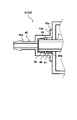
また、液体セル部71は、入口部41と出口部42とに接続されている。本実施形態では、入口部41と出口部42とは、同じ構造を有している。具体的には、図5に示すように、入口部41は、ハウジング部43から突出した円筒管(液体セル部71)を覆う継手部45と、継手部45と円筒管との隙間をシールするシール部材46で形成されている。この継手部45は、上流側の排液ライン52(第1の成分濃度検出器4aではメイン流路52a、第2の成分濃度検出器4bでは分岐流路52b)と接続される配管接続部45aと、液体セル部71と接続されるジョイント開口部45bとを有しており、フランジ部45cがハウジング部43にネジ45dで締結されることにより固定されるようになっている。ジョイント開口部45bは、配管接続部45a側に向かって狭くなるテーパ形状に形成されている。これにより、シール部材46が押圧されて固定されるようになっている。すなわち、ハウジング部43から突出する液体セル部71(円筒管)には、ハウジング部43側から第1カラー47、シール部材46(Oリング)、第2カラー48がこの順に互いに接するように配置されており、この状態でジョイント開口部45bを嵌め込んで固定する。すなわち、継手部45をハウジング部43にネジ止めすると、ジョイント開口部45bのテーパ部分がシール部材46と接した後、さらに継手部45がネジ45dで締結されることにより、テーパ部分でシール部材46が押圧される。シール部材46の両隣には、第1カラー47と第2カラー48が隣接しているため、テーパ部分で押圧されたシール部材46は、円筒管とテーパ部分とに膨張して密着することにより円筒管と継手部45とがシールされる。すなわち、排液ライン52から配管接続部45aに進入した液体は、ジョイント開口部45bから漏れることなく円筒管に流通し、再び出口部42から排液ライン52に流れ出る。このような継手部45の構成により、円筒管に何ら加工することなく液体セル部71として使用することができ、複雑な構成を有していた従来の液体セル部71に比べて安価な構成にすることができる。
このようにして、メイン流路52aに設けられた第1の成分濃度検出器4aでは、メイン流路52aに流れる液体に照射部81から照射されたUV光が液体セル部71の円筒管を通過し受光部91で受光されることにより、液体中の老廃物である尿素、尿酸等の濃度が計測され、透析中の患者の透析状態をリアルタイムで把握することができる。
また、分岐流路52bに設けられた第2の成分濃度検出器4bでは、アルブミン濃度を検出することができる。すなわち、排液ライン52に液体を流通させて第1の成分濃度検出器4aでリアルタイムに濃度を計測している状態で、分岐流路52bのバルブ54を閉状態にすると、分岐流路52bに液体が滞留する。すなわち、図7に示すように、分岐流路52bのバルブ54を閉じると、分岐流路52bを流れていた液体が行き場を失い、分岐流路52b内に停滞する(滞留部56が形成される)結果、分岐流路52bに接続される第2の成分濃度検出器4bの液体セル部71を流れる液体も液体セル部71に滞留する。そして、第2の成分濃度検出器4bの照射部81からUV光(本実施形態では波長240~260nmに設定されている。)が照射されると、液体セル部71内のアルブミンが時間とともに変性し、液体セル部71における液体が白濁する。すなわち、液体セル部71に照射された光は受光部91で受光されるが、白濁した液体により受光量が変化する。そして、液体中のアルブミン量の変化すると白濁状態も変化するため、この滞留部56における受光量を計測することによりアルブミン濃度を計測することができる。すなわち、透析状態の経過の観察と同時に、肝臓、腎臓の機能状態、及び、栄養状態等(健康状態と称す)の観察も行うことができる。したがって、第1の成分濃度検出器4aにより尿素、尿酸等の濃度を計測して透析状態を把握つつ、それと同時に共通の送液回路内で、第2の成分濃度検出器4bによりアルブミン濃度を検出して透析中の患者の健康状態も同時に把握することができる。
なお、上記実施形態では、第1の成分濃度検出器4aの下流側に分岐流路52bを設け第2の成分濃度検出器4bを配置する例について説明したが、第1の成分濃度検出器4aの上流側に分岐流路52bを設け第2の成分濃度検出器4bを配置するものであってもよい。この構成であっても、分岐流路52bに液体を滞留させることにより、第2の成分濃度検出器4bによりアルブミン濃度を計測することができる。
また、上記実施形態では、照射部81から照射されるUV光が、波長240~260nmに設定されている例について説明したが、滞留する液体に照射した結果、アルブミンが変性する波長であれば、他の波長の光を使用するものであってもよい。
また、上記実施形態では、集光部10が液体セル部71と一体化された例について説明したが、液体セル部71と排液モニタ部9との間に例えば凸レンズ等、光を一定領域に集光できる部材を集光部10として配置するものであってもよい。この場合でも液体セル部71を通過した光を一定領域に集光させて受光部91に受光させることにより、受光部91における受光強度が大きくなるため、液体の成分濃度検出精度を向上させることができる。
また、上記実施形態では、液体セル部71に石英製の円筒管を使用したが、円筒管が他の部材で形成されていてもよい。すなわち、上記実施形態では、UV光が照射されるため、UV光の吸収が極めて少ない石英製を例に挙げたが、照射部81から照射される光の吸収が抑えられる部材で形成されれば、液体セル部71を流れる液体以外の部材による光の吸収が抑えられ、濃度検出精度を高めることができる点で好ましい。
また、上記実施形態では、液体セル部71に円筒管を使用したが、集光部10を別途設ける場合には、照射部81からの光に直交する平行平板で形成される液体セル部71(照射方向に対して垂直な平面状に形成された液体セル部)であってもよい。
また、上記実施形態では、照射部81に冷陰極管UVランプ81aを使用しコストダウンを図れる例について説明したが、LEDランプを使用する構成であってもよい。
また、上記実施形態では、液体セル部71がセル枠体部72に設けられ、セル枠体部72が着脱自在である例について説明したが、液体セル部71がハウジング部43と一体化して直接固定されているものであってもよい。
1 血液透析装置
4 成分濃度検出器
4a 第1の成分濃度検出器
4b 第2の成分濃度検出器
6 成分濃度検出システム
52 排液ライン
52a メイン流路
52b 分岐流路
54 バルブ
56 滞留部
71 液体セル部
72 セル枠体部
81 照射部
81a 冷陰極管UVランプ
85 第2受光部
91 受光部
4 成分濃度検出器
4a 第1の成分濃度検出器
4b 第2の成分濃度検出器
6 成分濃度検出システム
52 排液ライン
52a メイン流路
52b 分岐流路
54 バルブ
56 滞留部
71 液体セル部
72 セル枠体部
81 照射部
81a 冷陰極管UVランプ
85 第2受光部
91 受光部
Claims (4)
- 成分濃度を検出される対象となる液体が流れる流路に設けられ、前記液体に光を照射してその光吸収度合いから液体中の成分濃度を検出する第1の成分濃度検出器と、
前記流路を流れる液体を滞留させる滞留部と、
前記滞留部で滞留される前記液体に光を照射してその光吸収度合いから液体中の成分濃度を検出する第2の成分濃度検出器と、
を備えることを特徴とする成分濃度検出システム。 - 前記滞留部は、前記液体が送液される前記流路から分岐された分岐流路と、この分岐流路に設けられたバルブによって形成されており、前記第2の成分濃度検出器は、前記分岐流路に滞留する液体の成分濃度を検出することを特徴とする請求項1に記載の成分濃度検出システム。
- 前記第1及び第2の成分濃度検出器は、光を照射する照射部と、照射部から照射された光を受光する受光部と、前記照射部と前記受光部との間に配置され、前記液体が流通する液体セル部と、を有しており、
前記液体セル部は、円筒管で形成されていることを特徴とする請求項1又は2に記載の成分濃度検出システム。 - 前記液体は、血液浄化装置から排出された排液であり、この排液に照射される光の波長は240~260nmであることを特徴とする請求項1~3のいずれかに記載の成分濃度検出システム。
Priority Applications (1)
| Application Number | Priority Date | Filing Date | Title |
|---|---|---|---|
| US16/476,186 US10874785B2 (en) | 2017-01-11 | 2017-12-08 | Component concentration sensing system |
Applications Claiming Priority (2)
| Application Number | Priority Date | Filing Date | Title |
|---|---|---|---|
| JP2017002744A JP6698558B2 (ja) | 2017-01-11 | 2017-01-11 | 成分濃度検出システム |
| JP2017-002744 | 2017-01-11 |
Publications (1)
| Publication Number | Publication Date |
|---|---|
| WO2018131348A1 true WO2018131348A1 (ja) | 2018-07-19 |
Family
ID=62839964
Family Applications (1)
| Application Number | Title | Priority Date | Filing Date |
|---|---|---|---|
| PCT/JP2017/044119 Ceased WO2018131348A1 (ja) | 2017-01-11 | 2017-12-08 | 成分濃度検出システム |
Country Status (3)
| Country | Link |
|---|---|
| US (1) | US10874785B2 (ja) |
| JP (1) | JP6698558B2 (ja) |
| WO (1) | WO2018131348A1 (ja) |
Cited By (1)
| Publication number | Priority date | Publication date | Assignee | Title |
|---|---|---|---|---|
| WO2026063114A1 (ja) * | 2024-09-17 | 2026-03-26 | ダイキン工業株式会社 | 液体状態センサ、液状態判定装置、及び油圧ユニット |
Families Citing this family (1)
| Publication number | Priority date | Publication date | Assignee | Title |
|---|---|---|---|---|
| JP7472600B2 (ja) * | 2020-03-30 | 2024-04-23 | 株式会社ジェイ・エム・エス | 濃度測定装置及び濃度測定方法 |
Citations (14)
| Publication number | Priority date | Publication date | Assignee | Title |
|---|---|---|---|---|
| JPS5322790A (en) * | 1976-08-16 | 1978-03-02 | Asahi Medical Co | Detector for leaking blood from artificial viscera |
| JPH08278247A (ja) * | 1995-02-07 | 1996-10-22 | Jasco Corp | フローセルアッセンブリ |
| JP2009222412A (ja) * | 2008-03-13 | 2009-10-01 | Jms Co Ltd | 成分測定用器具及び成分測定用器具を備えた血液透析装置 |
| JP2011514182A (ja) * | 2008-02-04 | 2011-05-06 | ザ トラスティーズ オブ コロンビア ユニバーシティ イン ザ シティ オブ ニューヨーク | 流体分離装置、システム、及び方法 |
| JP2011120823A (ja) * | 2009-12-14 | 2011-06-23 | Nikkiso Co Ltd | 血液浄化装置 |
| JP2011120822A (ja) * | 2009-12-14 | 2011-06-23 | Nikkiso Co Ltd | 血液浄化装置 |
| JP2012040058A (ja) * | 2010-08-13 | 2012-03-01 | Asahi Kasei Kuraray Medical Co Ltd | 血液成分濃度測定装置及び血液成分濃度測定方法 |
| JP2013122397A (ja) * | 2011-12-09 | 2013-06-20 | Jasco Corp | 高耐圧蛍光フローセル、フローセルアッセンブリ、蛍光検出器および超臨界流体クロマトグラフ |
| JP2013144057A (ja) * | 2012-01-16 | 2013-07-25 | Rion Co Ltd | 透析用生物粒子計数器、透析用生物粒子計数方法、及び、透析液監視システム |
| JP2014518517A (ja) * | 2011-04-11 | 2014-07-31 | フレゼニウス メディカル ケアー ドイチュラント ゲゼルシャフト ミット ベシュレンクテル ハフツング | 患者の治療、好ましくは血液透析、血液透析濾過、および腹膜透析の少なくとも1つを監視する方法および装置 |
| JP2015047349A (ja) * | 2013-09-02 | 2015-03-16 | 日機装株式会社 | 血液浄化装置 |
| JP2015186507A (ja) * | 2014-03-26 | 2015-10-29 | 旭化成メディカル株式会社 | 血液浄化装置 |
| US20160058934A1 (en) * | 2013-04-03 | 2016-03-03 | B.Braun Avitum Ag | System for detecting a state of a dialyzer apparatus, and sensor device which can be used for this purpose |
| JP2016099311A (ja) * | 2014-11-26 | 2016-05-30 | 横河電機株式会社 | 試料測定装置 |
Family Cites Families (6)
| Publication number | Priority date | Publication date | Assignee | Title |
|---|---|---|---|---|
| US6284142B1 (en) * | 1999-09-03 | 2001-09-04 | Baxter International Inc. | Sensing systems and methods for differentiating between different cellular blood species during extracorporeal blood separation or processing |
| CN103454192B (zh) * | 2003-07-02 | 2016-08-24 | 泰尔茂比司特公司 | 一种用于提取端口中细胞分离室光学表面的光学单元 |
| JP2011120821A (ja) * | 2009-12-14 | 2011-06-23 | Nikkiso Co Ltd | 血液浄化装置 |
| CN103347550A (zh) * | 2010-11-17 | 2013-10-09 | 弗雷泽纽斯医疗保健控股公司 | 用于光学监视系统的传感器夹组件 |
| US10281454B2 (en) * | 2015-06-24 | 2019-05-07 | Fresenius Medical Care Holdings, Inc. | Tunable optical receiver |
| CN107683109B (zh) * | 2015-06-25 | 2021-06-08 | 费森尤斯医疗控股股份有限公司 | 直接光差分测量系统 |
-
2017
- 2017-01-11 JP JP2017002744A patent/JP6698558B2/ja not_active Expired - Fee Related
- 2017-12-08 WO PCT/JP2017/044119 patent/WO2018131348A1/ja not_active Ceased
- 2017-12-08 US US16/476,186 patent/US10874785B2/en not_active Expired - Fee Related
Patent Citations (14)
| Publication number | Priority date | Publication date | Assignee | Title |
|---|---|---|---|---|
| JPS5322790A (en) * | 1976-08-16 | 1978-03-02 | Asahi Medical Co | Detector for leaking blood from artificial viscera |
| JPH08278247A (ja) * | 1995-02-07 | 1996-10-22 | Jasco Corp | フローセルアッセンブリ |
| JP2011514182A (ja) * | 2008-02-04 | 2011-05-06 | ザ トラスティーズ オブ コロンビア ユニバーシティ イン ザ シティ オブ ニューヨーク | 流体分離装置、システム、及び方法 |
| JP2009222412A (ja) * | 2008-03-13 | 2009-10-01 | Jms Co Ltd | 成分測定用器具及び成分測定用器具を備えた血液透析装置 |
| JP2011120823A (ja) * | 2009-12-14 | 2011-06-23 | Nikkiso Co Ltd | 血液浄化装置 |
| JP2011120822A (ja) * | 2009-12-14 | 2011-06-23 | Nikkiso Co Ltd | 血液浄化装置 |
| JP2012040058A (ja) * | 2010-08-13 | 2012-03-01 | Asahi Kasei Kuraray Medical Co Ltd | 血液成分濃度測定装置及び血液成分濃度測定方法 |
| JP2014518517A (ja) * | 2011-04-11 | 2014-07-31 | フレゼニウス メディカル ケアー ドイチュラント ゲゼルシャフト ミット ベシュレンクテル ハフツング | 患者の治療、好ましくは血液透析、血液透析濾過、および腹膜透析の少なくとも1つを監視する方法および装置 |
| JP2013122397A (ja) * | 2011-12-09 | 2013-06-20 | Jasco Corp | 高耐圧蛍光フローセル、フローセルアッセンブリ、蛍光検出器および超臨界流体クロマトグラフ |
| JP2013144057A (ja) * | 2012-01-16 | 2013-07-25 | Rion Co Ltd | 透析用生物粒子計数器、透析用生物粒子計数方法、及び、透析液監視システム |
| US20160058934A1 (en) * | 2013-04-03 | 2016-03-03 | B.Braun Avitum Ag | System for detecting a state of a dialyzer apparatus, and sensor device which can be used for this purpose |
| JP2015047349A (ja) * | 2013-09-02 | 2015-03-16 | 日機装株式会社 | 血液浄化装置 |
| JP2015186507A (ja) * | 2014-03-26 | 2015-10-29 | 旭化成メディカル株式会社 | 血液浄化装置 |
| JP2016099311A (ja) * | 2014-11-26 | 2016-05-30 | 横河電機株式会社 | 試料測定装置 |
Cited By (2)
| Publication number | Priority date | Publication date | Assignee | Title |
|---|---|---|---|---|
| WO2026063114A1 (ja) * | 2024-09-17 | 2026-03-26 | ダイキン工業株式会社 | 液体状態センサ、液状態判定装置、及び油圧ユニット |
| JP2026054772A (ja) * | 2024-09-17 | 2026-03-30 | ダイキン工業株式会社 | 液体状態センサ、液状態判定装置、及び油圧ユニット |
Also Published As
| Publication number | Publication date |
|---|---|
| US10874785B2 (en) | 2020-12-29 |
| US20200023114A1 (en) | 2020-01-23 |
| JP6698558B2 (ja) | 2020-05-27 |
| JP2018112462A (ja) | 2018-07-19 |
Similar Documents
| Publication | Publication Date | Title |
|---|---|---|
| US7537688B2 (en) | Blood purification device | |
| JP6027720B2 (ja) | 血液浄化装置 | |
| CN100486649C (zh) | 血细胞比容传感器 | |
| US8518247B2 (en) | Error correction for a liquid concentration detector of a blood purification apparatus | |
| CN105142691B (zh) | 用于检测透析器设备的状态的系统和可用于此目的的传感器装置 | |
| CN105473170B (zh) | 血液净化装置 | |
| US20070023334A1 (en) | Apparatus, a system and a method relating to hemodialysis, hemodiafiltration, hemofiltration or peritoneal dialysis | |
| BR112013026319B1 (pt) | método e aparelho para o monitoramento de um tratamento de um paciente, preferivelmente para o monitoramento da hemodiálise, hemodiafiltração e/ou diálise peritoneal | |
| JP3949756B2 (ja) | 透析器の膜の機能安全性をモニタする装置 | |
| RU2014133177A (ru) | Устройство для экстракорпоральной очистки крови и способ компенсации изменений интенсивности источника электромагнитного излучения в нем | |
| US9370614B2 (en) | Recirculation detection by administration of a bolus | |
| JP2007105149A (ja) | 血液浄化装置及びその再循環率算出方法 | |
| WO2018131348A1 (ja) | 成分濃度検出システム | |
| JP2017127635A (ja) | 濃度測定モジュール、透析装置及び濃度算出方法 | |
| WO2018088286A1 (ja) | 成分濃度検出器 | |
| SE8406576L (sv) | Anordning for automatisk effektivitetsbestemning vid hemodialys | |
| JP2009222412A (ja) | 成分測定用器具及び成分測定用器具を備えた血液透析装置 | |
| WO2023058732A1 (ja) | 血液浄化装置 | |
| CN222998096U (zh) | 一种用于血液透析的光学分析安装结构 | |
| JPS5896234A (ja) | 漏血検出方法及びその装置 | |
| JP7814965B2 (ja) | 検出装置及び血液処理システム | |
| CN118914089A (zh) | 一种透析充分性评测系统及方法 | |
| JP2012237758A (ja) | 成分測定用器具及び成分測定用器具を備えた血液透析装置 | |
| JP2007105148A (ja) | 血液浄化装置及びその再循環率算出方法 | |
| JP2019063523A (ja) | マルチセンサ装置 |
Legal Events
| Date | Code | Title | Description |
|---|---|---|---|
| 121 | Ep: the epo has been informed by wipo that ep was designated in this application |
Ref document number: 17891659 Country of ref document: EP Kind code of ref document: A1 |
|
| NENP | Non-entry into the national phase |
Ref country code: DE |
|
| 122 | Ep: pct application non-entry in european phase |
Ref document number: 17891659 Country of ref document: EP Kind code of ref document: A1 |