WO2018131232A1 - 送信制御装置、受信制御装置および送受信制御システム - Google Patents
送信制御装置、受信制御装置および送受信制御システム Download PDFInfo
- Publication number
- WO2018131232A1 WO2018131232A1 PCT/JP2017/036594 JP2017036594W WO2018131232A1 WO 2018131232 A1 WO2018131232 A1 WO 2018131232A1 JP 2017036594 W JP2017036594 W JP 2017036594W WO 2018131232 A1 WO2018131232 A1 WO 2018131232A1
- Authority
- WO
- WIPO (PCT)
- Prior art keywords
- transmission
- lane
- unit
- pixel data
- transmission frame
- Prior art date
- Legal status (The legal status is an assumption and is not a legal conclusion. Google has not performed a legal analysis and makes no representation as to the accuracy of the status listed.)
- Ceased
Links
Images





Classifications
-
- H—ELECTRICITY
- H04—ELECTRIC COMMUNICATION TECHNIQUE
- H04N—PICTORIAL COMMUNICATION, e.g. TELEVISION
- H04N21/00—Selective content distribution, e.g. interactive television or video on demand [VOD]
- H04N21/40—Client devices specifically adapted for the reception of or interaction with content, e.g. set-top-box [STB]; Operations thereof
- H04N21/43—Processing of content or additional data, e.g. demultiplexing additional data from a digital video stream; Elementary client operations, e.g. monitoring of home network or synchronising decoder's clock; Client middleware
- H04N21/436—Interfacing a local distribution network, e.g. communicating with another STB or one or more peripheral devices inside the home
Definitions
- the present disclosure relates to a transmission control device, a reception control device, and a transmission / reception control system.
- HDMI High-Definition Multimedia Interface
- DP Display Port
- a transmission frame generation unit that generates a transmission frame based on a plurality of pixel data included in a video signal, and a lane in which each of the plurality of pixel data is transmitted after a predetermined change timing is changed. And a lane changing unit.
- the signal acquisition unit when a transmission frame generated based on a plurality of pixel data included in a video signal is received, the signal acquisition unit includes the signal acquisition unit that acquires the plurality of pixel data from the transmission frame.
- the reception control device is provided that obtains the plurality of pixel data in which the lane transmitted after the predetermined change timing is detected is changed.
- a transmission frame generation unit that generates a transmission frame based on a plurality of pixel data included in a video signal, and a lane in which each of the plurality of pixel data is transmitted after a predetermined change timing is changed.
- a transmission control device comprising a lane changing unit, and a signal acquisition unit that acquires the plurality of pixel data from the transmission frame when the transmission frame is received, wherein the signal acquisition unit is transmitted.
- a transmission / reception control system including a reception control device that acquires the plurality of pixel data whose lanes are changed.
- the transmission state of a lane in which a part or all of the video signal is transmitted among a plurality of lanes deteriorates, the visibility of the video displayed on the reception side is improved.
- a technology capable of being provided is provided. Note that the above effects are not necessarily limited, and any of the effects shown in the present specification, or other effects that can be grasped from the present specification, together with or in place of the above effects. May be played.
- HDMI, DP, and the like are known as techniques for transmitting a video signal (Video signal) using a plurality of lanes.
- pixel data is assigned to one of a plurality of lanes for each color information, and pixel data is transmitted based on the lane assignment for the color information.
- coordinates are assigned to any of a plurality of lanes, and pixel data is transmitted based on the assignment of lanes to the coordinates.
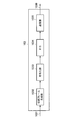
- FIG. 1 is a diagram illustrating an example of a configuration of a signal transmission system 1A according to the first embodiment.
- the signal transmission system 1A includes a transmission device 10A and a reception device 20A.
- the transmission device 10 ⁇ / b> A and the reception device 20 ⁇ / b> A are connected via a transmission path 30.
- a video signal is handled as a transmission signal from the transmission device 10A to the reception device 20A
- a transmission signal is transmitted by an optical signal
- the transmission signal may be transmitted / received not by an optical signal but by another signal such as an electrical signal.
- the transmitting apparatus 10A can function as a “transmission control apparatus”.
- the receiving device 20A can function as a “reception control device”.
- the signal transmission system 1A can function as a “transmission / reception control system”.
- the transmitting apparatus 10A divides the video signal (Video signal) into a plurality of signals (hereinafter also referred to as “divided signals”), and transmits the plurality of divided signals based on the lane allocation for each of the plurality of divided signals. As will be described later, the video signal may be transmitted by one lane without being divided into a plurality of divided signals by the transmission device 10A.
- the video signal 101 is input to the transmission device 10A.
- the video signal 101 is composed of a plurality of video frames (images) along a time series.
- the transmitting apparatus 10A includes an image dividing unit (lane changing unit) 102 and transmission frame transmitting units 103-1 to 103-M.
- the image dividing unit 102 divides the video signal to obtain a plurality of divided signals.
- the maximum number of divisions may be M (M is an integer of 2 or more), which is the number of lanes 303. That is, all of the M lanes 303 may be used for transmission of video signals, or only a part may be used for transmission of video signals (an empty lane may exist).
- M is an integer of 2 or more
- the division number of the video signal is “4” will be mainly described, but the division number of the video signal is not limited.
- the unit of division is not limited to the coordinate unit, and may be a block unit constituted by a plurality of coordinates.
- the image dividing unit 102 specifies a lane to which each of a plurality of pixel data included in the video signal is transmitted before a predetermined change timing.
- a predetermined change timing is not limited.
- the image dividing unit 102 specifies the lane to which each of the plurality of pixel data is transmitted based on the lane assignment to each coordinate of the video signal before the change timing.
- Each of the plurality of pixel data included in the video signal is output to transmission frame transmission units 103-1 to 103-4 connected to the lane specified by the image division unit 102 among the transmission frame transmission units 103-1 to 103-M. Is done. Further, the image dividing unit 102 changes the lane assignment to each coordinate in the video signal after a predetermined change timing. When the lane assignment for each coordinate is changed, in each of the transmission frame transmission units 103-1 to 103-4, a transmission frame is generated by the transmission frame generation unit 1032 according to the changed assignment, and the transmission unit 1035 transmits the transmission frame. Is sent.
- the transmission frame transmitting unit 103-1 generates a transmission frame based on the pixel data group (divided signal) input from the image dividing unit 102. Then, the transmission frame transmission unit 103-1 transmits the generated transmission frame to the lane 303-1 connected to itself.
- Each of the transmission frame transmitting units 103-2 to 103-4 generates a transmission frame based on the pixel data group (divided signal) input from the image dividing unit 102, similarly to the transmission frame transmitting unit 103-1.
- the transmitted frame is transmitted to lanes 303-2 to 303-4 connected to itself.
- FIG. 2 is a diagram illustrating an example of a detailed configuration of the transmission frame transmission unit 103 according to the first embodiment.
- the input port 1031 is a port to which a pixel data group (divided signal) is input.
- the transmission frame transmission unit 103 includes a transmission frame generation unit 1032, an encoding unit 1033, a P / S (parallel serial conversion unit) 1034, and a transmission unit 1035. Below, the function of each of these functional blocks will be described.
- the transmission frame generation unit 1032 When a pixel data group (division signal) is input from the input port 1031, the transmission frame generation unit 1032 generates a transmission frame by framing the pixel data group (division signal).
- the framing may be done in any way.
- the transmission frame generation unit 1032 may perform framing by attaching a frame start identifier indicating the head of the transmission frame to the pixel data group (divided signal).
- At least one of predetermined codes (hereinafter also referred to as “special data”) that does not exist in the video signal is assigned to the frame start identifier.
- the special data depends on the encoding of data transmitted / received through the lane 303.
- a K code may be assigned to the special data.
- data in which N bytes of K code (0xBC) called K28.5 are continuous may be assigned to the frame start identifier.
- the encoding unit 1033 encodes the pixel data group (divided signal). Specifically, the encoding unit 1033 performs 8b / 10b encoding on the pixel data group (divided signal). At this time, the encoding unit 1033 may replace the frame start identifier with the corresponding special data in the pixel data group (divided signal) and replace data other than the frame start identifier with 10-bit unit data.
- P / S 1034 converts the encoded pixel data group (divided signal) from parallel data to serial data in a format suitable for high-speed transmission.
- the transmission unit 1035 transmits a transmission frame.
- the transmission frame is output from the output terminal 1036.
- the transmission unit 1035 includes an LDD (laser diode driver) and an LD (laser diode).
- the LDD drives the LD
- the LD outputs the transmission frame input from the LDD from the output terminal 1036.
- the lane 303 is configured by an optical fiber
- the LD converts the transmission frame into an optical signal and then transmits the optical signal to the receiving device 20A.
- the signal type of the transmission frame is not limited.
- the transmission device 10A may transmit a transmission frame to the reception device 20A by an electrical signal.
- the transmission path 30 includes lanes 303-1 to 303-M (M is an integer of 2 or more).
- M is an integer of 2 or more.
- the number of lanes 303 is shown as M, but the number of lanes 303 is not particularly limited as long as it is plural.
- the receiving device 20A receives a plurality of divided signals from the lanes 303-1 to 303-M, and generates a video signal based on the received plurality of divided signals.
- the receiving apparatus 20A includes transmission frame receiving units 203-1 to 203-M and an image synthesizing unit 202. Each of the transmission frame receiving units 203-1 to 203-M is connected to a corresponding lane 303-1 to 303-M. As described above, in the present embodiment, the case where the number of divisions of the video signal is “4” will be mainly described.
- the transmission frame receiving unit 203-1 receives the transmission frame from the lane 303-1, and acquires a pixel data group (divided signal) from the received transmission frame.
- the transmission frame receiving units 203-2 to 203-4 also receive the transmission frame from the lanes 303-2 to 303-4, and acquire pixel data groups (divided signals) from the transmission frame.
- FIG. 3 is a diagram illustrating an example of a detailed configuration of the transmission frame receiving unit 203 according to the first embodiment.
- the input port 2036 is a port to which a transmission frame is input.
- a transmission frame input from the input port 2036 is input to the transmission frame receiving unit 203.
- the transmission frame reception unit 203 includes a reception unit 2035, an S / P (serial / parallel conversion unit) 2034, a decoding unit 2033, and a signal acquisition unit 2032.
- S / P serial / parallel conversion unit
- the reception unit 2035 receives the transmission frame.
- the receiving unit 2035 includes a PD (photo detector) and an amplifier.
- the PD receives the transmission frame transmitted by the optical signal from the transmitter 10A and converts it into an electrical signal.
- the lane 303 is configured by an optical fiber, and the PD receives a transmission frame and converts it into an electrical signal.
- the transmission is performed from the transmission device 10A to the reception device 20A.
- the type of signal to be performed is not limited.
- the receiving device 20A may receive a transmission frame from the transmitting device 10A by an electrical signal.
- the amplifier amplifies the transmission frame as an electrical signal output from the PD, and outputs the amplified transmission frame to the S / P 2034.
- the amplifier may perform amplitude amplification on the voltage signal after obtaining a voltage signal by performing impedance conversion on the current signal.
- S / P 2034 converts the format of the transmission frame from serial data to parallel data.
- the decoding unit 2033 decodes the transmission frame converted into parallel data. Specifically, the decoding unit 2033 may perform 8b / 10b decoding on the transmission frame. For example, the decoding unit 2033 may replace the 10-bit special data corresponding to the frame start identifier in the transmission frame with the frame start identifier. On the other hand, the decoding unit 2033 may replace the remaining data in the transmission frame with 8-bit data.
- the signal acquisition unit 2032 Since the input transmission frame is framed, the signal acquisition unit 2032 obtains a pixel data group (divided signal) by canceling this framed. More specifically, the signal acquisition unit 2032 detects the position of the frame start identifier replaced from the special code as the start position of the transmission frame. The signal acquisition unit 2032 obtains a pixel data group (divided signal) based on the position of the frame start identifier. The pixel data group (divided signal) obtained by the signal acquisition unit 2032 is output from the output port 2031.
- the image synthesis unit 202 generates a video signal by synthesizing pixel data groups (divided signals) output from the transmission frame reception units 203-1 to 203-4. That is, the image composition unit 202 corresponds to the image dividing unit 102 in the transmission device 10A.
- the image composition unit 202 identifies the lane from which each of the plurality of pixel data is acquired based on the lane assignment to each coordinate in the video signal before a predetermined change timing.
- the lane assignment for each coordinate in the video signal is the same between the image composition unit 202 and the image division unit 102 in the transmission apparatus 10A.
- the image combining unit 202 generates a video signal by combining a plurality of pixel data according to the specified lane.
- the video signal 201 generated by the image composition unit 202 is output to a predetermined output destination.
- the image composition unit 202 changes the lane assignment for each coordinate in the video signal after the change timing.
- the lane assignment after the change is the same between the image composition unit 202 and the image dividing unit 102 in the transmission apparatus 10A. Therefore, the assignment change by the image dividing unit 102 and the assignment change by the image composition unit 202 correspond to each other.
- the transmission frame reception units 203-1 to 203-4 receive the transmission frame by the reception unit 2035 according to the changed assignment, and the signal acquisition unit 2032 receives the transmission frame from the transmission frame.
- a pixel data group (divided signal) is acquired.
- the image synthesis unit 202 identifies a lane to which each of the plurality of divided signals is transmitted according to the changed assignment, and generates a video signal by synthesizing the plurality of divided signals according to the identified lane.
- FIG. 4 is a diagram illustrating a configuration example of a video frame included in a video signal.
- the video frame forms a rectangular shape in which X pixel data in the horizontal direction and Y pixel data in the vertical direction are arranged. Therefore, pixel data exists corresponding to each coordinate of the video frame.
- P (4, 5) indicates pixel data whose X coordinate is “4” and Y coordinate is “5”.
- the pixel data is composed of color information such as RGB.
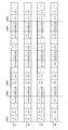
- FIG. 5 is a diagram showing an example of a pixel data group (divided signal) transmitted through each of lanes # 1 to # 4 in time series.
- transmission of the first video frame is started (first video frame start position 3031).
- lane # 1 is assigned to P (1,1)
- lane # 2 is assigned to P (2,1)
- lane # 3 is assigned to P (3,1)
- P (4,1 Lane # 4 is assigned to.
- the image dividing unit 102 specifies a lane to which each of a plurality of pixel data is transmitted according to the assignment.
- Each of the plurality of pixel data is transmitted to the lane connected to the lane specified by the image dividing unit 102.
- Lane # 4 is assigned to.
- the image dividing unit 102 specifies a lane to which each of a plurality of pixel data is transmitted according to the assignment. Each of the plurality of pixel data is transmitted to the lane connected to the lane specified by the image dividing unit 102.
- the first line of the first video frame is sequentially transmitted in the horizontal direction.
- first line end position 3032 When transmission of the first line of the first video frame is completed (first line end position 3032), the H blank section is transmitted, and when transmission of the H blank section is completed (H blank section end position 3033), the first sheet Transmission of the second line of the video frame is started.
- lane # 1 is assigned to P (1,2)
- lane # 2 is assigned to P (2,2)
- lane # 3 is assigned to P (3,2)
- P (4,2 Lane # 4 is assigned to.
- the image dividing unit 102 specifies a lane to which each of a plurality of pixel data is transmitted according to the assignment. Each of the plurality of pixel data is transmitted to the lane connected to the lane specified by the image dividing unit 102.
- the second line of the first video frame is transmitted sequentially in the horizontal direction.
- the V blank section is transmitted and the V blank section is transmitted.
- Transmission of the second video frame is started (second video frame start position 3035).
- the image dividing unit 102 changes the lane assignment for each coordinate in the video signal.
- lane # 1 is assigned to P (4,1)
- lane # 2 is assigned to P (1,1)
- lane # 3 is assigned to P (2,1)
- Lane # 4 is assigned to P (3, 1).
- the assignment for P (1,1) is changed from lane # 1 to lane # 2
- the assignment for P (2,1) is changed from lane # 2 to lane # 3
- P (3,1) The assignment for is changed from lane # 3 to lane # 4
- the assignment for P (4,1) is changed from lane # 4 to lane # 1.
- the assignment to P (1,1) is changed from lane # 2 to lane # 3, and the assignment to P (2,1) is changed to lane #. 3 to lane # 4, the assignment to P (3,1) is changed from lane # 4 to lane # 1, and the assignment to P (4,1) is changed from lane # 1 to lane # 2.
- the image dividing unit 102 changes the lane assignment to each coordinate in the video signal every time a video frame is transmitted as an example.
- the image dividing unit 102 changes the lane assignment for each coordinate in the video signal after a predetermined change timing.
- the coordinates of the pixel data that is not normally displayed change because the coordinates corresponding to the lane in which the transmission state deteriorates change. To do. Therefore, according to the first embodiment of the present disclosure, it is possible to improve the visibility of the video displayed on the reception side even if the transmission state of the lane in which the video signal is transmitted among the plurality of lanes deteriorates. It becomes possible.
- the change timing is not limited to this.
- the change timing may be one or more times during transmission of a transmission frame, or may be every time transmission of a plurality of transmission frames ends.
- the video signal may be transmitted through one lane without being divided into a plurality of divided signals.
- the image dividing unit 102 specifies the lane to which the entire video signal is transmitted based on the lane allocation to the entire video signal before the change timing. Then, the image dividing unit 102 changes the lane in which the entire video signal is transmitted after the change timing.
- FIG. 6 is a diagram illustrating an example of a configuration of a signal transmission system 1B according to the second embodiment. As illustrated in FIG. 6, the signal transmission system 1B includes a transmission device 10B and a reception device 20B.
- the transmission device 10B according to the second embodiment is mainly different from the transmission device 10A according to the first embodiment in that it includes a transmission control unit 107 and a transmission information generation unit 108.
- the receiving device 20B according to the second embodiment is mainly different from the receiving device 20A according to the first embodiment in that the receiving device 20B includes a reception control unit 207 and a transmission information detection unit 208.
- a configuration different from the first embodiment will be mainly described.
- the transmission control unit 107 controls the image division unit 102 and the transmission information generation unit 108 based on the input frame synchronization signal. More specifically, the transmission control unit 107 specifies control information including coordinates in the video signal and lanes assigned to the coordinates based on the input frame synchronization signal, and outputs the control information to the image dividing unit 102 To do. Further, the transmission control unit 107 outputs control information to the transmission information generation unit 108.
- the transmission information generation unit 108 generates transmission information according to the control information, and outputs the transmission information to each of the transmission frame transmission units 103-1 to 103-4.
- the transmission information is information obtained by converting the control information into a format that matches the transmission frame.
- the format is not limited, and the transmission information and control information may be the same.
- the image dividing unit 102 changes the lane assignment to the coordinates according to the control information input from the transmission control unit 107.
- the transmission frame generating unit 1032 inserts transmission information input from the transmission control unit 107 into the transmission frame.
- the transmission frame generation unit 1032 inserts transmission information at the start position of the transmission frame.
- the transmission information insertion position is not limited.
- FIG. 7 is a diagram illustrating a configuration example of the transmission frame transmission unit 103 according to the second embodiment.
- transmission information is input from the input port 1037 to the transmission frame generation unit 1032.
- the transmission frame generation unit 1032 inserts transmission information at the start position of the transmission frame.
- the transmission frame in which the transmission information is inserted is transmitted to the receiving device 20B (FIG. 6).
- FIG. 8 is a diagram illustrating a configuration example of the transmission frame receiving unit 203 according to the second embodiment.
- the signal acquisition unit 2032 extracts transmission information from the transmission frame.
- the transmission information extracted by the signal acquisition unit 2032 is output from the output port 2037 to the transmission information detection unit 208.
- the transmission information detection unit 208 detects the transmission information output from the signal acquisition unit 2032 in each of the transmission frame reception units 203-1 to 203-4.
- the transmission information detection unit 208 extracts control information from the transmission information.
- the transmission information detection unit 208 outputs control information to the reception control unit 207.
- the reception control unit 207 controls the lane assignment change with respect to the coordinates by the image composition unit 202.
- the image composition unit 202 changes the lane assignment to the coordinates in accordance with the control by the reception control unit 207.
- the transmission frame is received by the receiving unit 2035 according to the changed allocation, and the transmission frame is received by the signal acquiring unit 2032 A pixel data group (divided signal) is acquired from. Then, the image synthesis unit 202 identifies a lane to which each of the plurality of divided signals is transmitted according to the changed assignment, and generates a video signal by synthesizing the plurality of divided signals according to the identified lane.
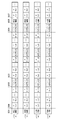
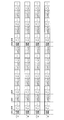
- FIG. 9 is a diagram showing an example of a pixel data group (divided signal) transmitted in each of lanes # 1 to # 4 and transmission information along a time series.
- the transmission frame generation unit 1032 inserts transmission information at a first video frame start position 3031 and a V blank interval end position (second video frame start position) 3035. At this time, the transmission of the pixel data is started from the pixel data start position 3036 and the pixel data start position 3037 where the transmission of the transmission information is completed.
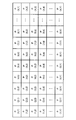
- FIG. 10 is a diagram illustrating an example of transmission information (control information) transmitted at the first video frame start position 3031.
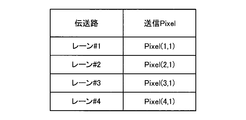
- the control information shown in FIG. 10 is formed by associating coordinates in the first video frame with lanes assigned to the coordinates.
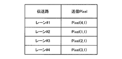
- FIG. 11 is a diagram illustrating an example of transmission information (control information) transmitted at the second video frame start position 3035.
- the control information shown in FIG. 11 is formed by associating coordinates in the first video frame with lanes assigned to the coordinates.
- transmission information (control information) indicating allocation of lanes to coordinates in the video signal is transmitted from the transmission device 10B to the reception device 20B together with the video signal.
- the transmission device 10B can control the timing for changing the allocation of lanes to coordinates.
- lane allocation can be appropriately performed from a transmission frame that has been successfully received.
- the transmission frame generation unit 1032 inserts transmission information (control information) into each of a plurality of transmission frames.
- the transmission frame generation unit 1032 may insert transmission information (control information) into the transmission frame only at the timing of changing the lane assignment to the coordinates.
- the example in which the transmission frame generation unit 1032 inserts transmission information (control information) at the start position of the transmission frame has been mainly described.
- the transmission frame generation unit 1032 may insert transmission information (control information) inside the transmission frame.
- the transmission control unit 107 designates control information different from the control information designated last time.
- the transmission control unit 107 may designate the same control information as the control information designated last time.
- the transmission frame generation unit may omit the insertion of the control information into the transmission frame.
- the image dividing unit 102 may change the lane allocation to the coordinates after a while after the transmission information (control information) is input (for example, after a predetermined number of transmission frames are transmitted).
- the image composition unit 202 may change the allocation of lanes to the coordinates after a while after the transmission information (control information) is input (for example, after a predetermined number of transmission frames are received).
- control information including the coordinates in the video signal and the lane assigned to the coordinates is transmitted together with the video information from the transmission device 10B to the reception device 20B.
- control information including a change pattern (or change pattern identification information) between the coordinates in the video signal and the lane assigned to the coordinates may be transmitted from the transmission device 10B to the reception device 20B together with the video information.
- FIG. 12 is a diagram showing a modification of the pixel data group (divided signal) transmitted in each of lanes # 1 to # 4 and transmission information along a time series.
- the transmission frame generation unit 1032 inserts transmission information at the first video frame start position 3031 and transmits the transmission frame for several frames, and then changes the change pattern. Transmission information is inserted into the V blank section end position (video frame start position) 3038. At this time, the transmission of the pixel data is started from the pixel data start position 3036 and the pixel data start position 3037 where the transmission of the transmission information is completed.
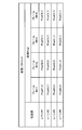
- FIG. 13 is a diagram illustrating an example of transmission information (control information) transmitted at the first video frame start position 3031.
- the control information shown in FIG. 13 includes a change pattern before change.
- FIG. 14 is a diagram illustrating an example of transmission information (control information) transmitted at the video frame start position 3038.
- the control information shown in FIG. 14 includes a changed pattern after change.
- the change pattern is expressed by a combination of coordinates and lanes corresponding to frames 4N (N is an integer of 0 or more) +1 to frames 4N + 4.
- N is an integer of 0 or more
- the coordinates and lanes of “Frame 4N + 1” are used for the first transmission frame
- the coordinates and lanes of “Frame 4N + 2” are used for the second transmission frame
- “Frame 4N + 3” is used for the third transmission frame.
- the coordinates and lanes of “frame 4N + 4” are used for the fourth transmission frame
- the coordinates and lanes of “frame 4N + 1” are used again for the fifth transmission frame, Thereafter, the same use is repeated.
- a lane assignment change pattern for coordinates is transmitted, the assignment can be changed according to the change pattern. Therefore, it is possible to reduce the data amount of transmission information transmitted from the transmission device 10B to the reception device 20B as compared to an example in which transmission information is transmitted each time a lane is changed with respect to coordinates (insertion of transmission information). Frequency can be reduced). Therefore, when a lane change pattern with respect to coordinates is transmitted, more video information can be transmitted.
- the lane allocation change pattern for the coordinates is transmitted, it is possible to reduce the frequency of transmission information insertion.
- transmission information is transmitted until the transmission information is received from the transmission device 10B. Accordingly, the lane cannot be assigned to the coordinates based on the above, and the output of the video signal cannot be started.
- the insertion frequency of transmission information is preferably determined in consideration of the time until the start of video signal output.
- control information may include the change pattern itself, and there is a correspondence between the change pattern identification information and the change pattern between the transmission device 10B and the reception device 20B. If shared, the control information may include change pattern identification information instead of the change pattern itself. According to such an example, it is possible to further reduce the amount of data transmitted from the transmission device 10B to the reception device 20B as compared to the case where the lane change pattern with respect to the coordinates is transmitted.
- the transmission frame generation unit 1032 that generates a transmission frame based on the plurality of pixel data included in the video signal, and the plurality of pixel data after a predetermined change timing
- a transmission device 10A including an image dividing unit (lane changing unit) 102 that changes the lane to which each is transmitted.
- each functional block included in the transmission device 10 may be mounted on a separate IC (Integrated Circuit), or any combination may be mounted on the same IC.
- each functional block included in the reception device 20 may be mounted on a separate IC, or any combination may be mounted on the same IC.
- a transmission frame generation unit that generates a transmission frame based on a plurality of pixel data included in the video signal;
- a lane changing unit that changes a lane in which each of the plurality of pixel data is transmitted after a predetermined change timing;
- a transmission control apparatus comprising: (2) The lane changing unit specifies a lane to which each of the plurality of pixel data is transmitted based on lane assignment to each coordinate in the video signal before the predetermined change timing.
- the transmission control device according to (1).
- the lane changing unit changes the lane assignment for each coordinate in the video signal after the predetermined change timing.
- the transmission control device according to (1) or (2).
- the predetermined change timing is one or more times during transmission of the transmission frame, each time transmission of each of the plurality of transmission frames ends, or each time transmission of the plurality of transmission frames ends.
- the transmission control device according to any one of (1) to (3).
- the transmission control device includes: A transmission control unit that specifies control information including coordinates in the video signal and lanes assigned to the coordinates; The transmission control apparatus according to any one of (1) to (4).
- the transmission control device includes: A transmission control unit that specifies control information including a change pattern of coordinates in the video signal and a lane assigned to the coordinates or identification information of the change pattern; The transmission control apparatus according to any one of (1) to (4).
- the transmission frame generation unit inserts the control information into the transmission frame.
- the transmission control device according to (5) or (6).
- the transmission frame generation unit inserts the control information in a start position of the transmission frame or in the transmission frame;
- the transmission control device according to (7).
- the transmission frame generation unit omits the insertion of the control information when the control information specified last time and this time is the same.
- the transmission control device according to (7) or (8).
- a signal acquisition unit that acquires the plurality of pixel data from the transmission frame, The signal acquisition unit acquires the plurality of pixel data in which lanes transmitted after detection of a predetermined change timing are changed, Reception control device.
- the reception control device includes: An image synthesis unit for synthesizing the plurality of pixel data; The image composition unit specifies a lane to which each of the plurality of pixel data is transmitted based on lane assignment to each coordinate in the video signal before the predetermined change timing.
- the reception control device according to (10).
- (12) The image composition unit changes the lane assignment for each coordinate in the video signal after the predetermined change timing.
- the reception control device according to (11).
- the predetermined change timing is one or more times during transmission of the transmission frame, each time transmission of each of the plurality of transmission frames ends, or each time transmission of the plurality of transmission frames ends.
- the reception control apparatus according to any one of (10) to (12).
- the reception control device includes: Based on control information including coordinates in the video signal and lanes assigned to the coordinates, a reception control unit that controls the lane assignment change by the image composition unit, The reception control device according to (11) or (12).
- the reception control device includes: A reception control unit for controlling the lane allocation change by the image synthesis unit based on control information including a change pattern of the coordinates in the video signal and a lane assigned to the coordinates or identification information of the change pattern; The reception control device according to (11) or (12).
- the signal acquisition unit extracts the control information from the transmission frame; The reception control device according to (14) or (15).
- the signal acquisition unit extracts the control information from a start position of the transmission frame or the transmission frame; The reception control device according to (16).
- the reception control device according to any one of (14) to (17).
- a transmission frame generation unit that generates a transmission frame based on a plurality of pixel data included in the video signal;
- a lane changing unit that changes a lane in which each of the plurality of pixel data is transmitted after a predetermined change timing;
- a transmission control device comprising: When the transmission frame is received, a signal acquisition unit that acquires the plurality of pixel data from the transmission frame, The signal acquisition unit acquires the plurality of pixel data in which the transmitted lane is changed.
- the lane changing unit changes the lane assignment for each coordinate in the video signal after the predetermined change timing.
- the transmission / reception control system according to (19).
- Signal transmission system 10 (10A, 10B) Transmission device 20 (20A, 20B) Reception device 102 Image segmentation unit 103 Transmission frame transmission unit 1031 Input port 1032 Transmission frame generation unit 1033 Encoding unit 1035 Transmission unit 1036 Output terminal 107 Transmission control unit 108 Transmission information generation unit 202 Image synthesis unit 203 Transmission frame reception unit 2031 Output port 2032 Signal acquisition unit 2033 Decoding unit 2035 Reception unit 2036 Input port 207 Reception control unit 208 Transmission information detection unit 30 Transmission path 303 Lane
Landscapes
- Engineering & Computer Science (AREA)
- Multimedia (AREA)
- Signal Processing (AREA)
- Two-Way Televisions, Distribution Of Moving Picture Or The Like (AREA)
- Controls And Circuits For Display Device (AREA)
Abstract
【課題】複数のレーンのうち映像信号の一部または全部が送信されるレーンの伝送状態が悪化しても、受信側において表示される映像の視認性を向上させることが可能な技術が提供されることが望まれる。 【解決手段】映像信号に含まれる複数のピクセルデータに基づいて伝送フレームを生成する伝送フレーム生成部と、所定の変更タイミングの後において前記複数のピクセルデータそれぞれが送信されるレーンを変更するレーン変更部と、を備える、送信制御装置が提供される。
Description
本開示は、送信制御装置、受信制御装置および送受信制御システムに関する。
近年、複数のレーンを用いて映像信号(Video信号)を送信する技術として、HDMI(High-Definition Multimedia Interface)、Display Port(以下、単に「DP」とも言う。)などが知られている。HDMIにおいては、ピクセル(Pixel)データを色情報ごとに複数のレーンのいずれかに割り当て、色情報に対するレーンの割り当てに基づいてピクセルデータが送信される。一方、DPにおいては、ピクセルデータを複数のレーンのいずれかに割り当て、ピクセルデータに対するレーンの割り当てに基づいてピクセルデータが送信される。
これに対し、1つのレーンに対して割り当てられる画面上の範囲を広くすることによって、特定のレーンが故障した場合に画面上の一部だけに画質の劣化が集中してしまうことを防止する技術が開示されている(例えば、特許文献1参照)。
しかし、複数のレーンのうち映像信号の一部または全部が送信されるレーンの伝送状態が悪化しても、受信側において表示される映像の視認性を向上させることが可能な技術が提供されることが望まれる。
本開示によれば、映像信号に含まれる複数のピクセルデータに基づいて伝送フレームを生成する伝送フレーム生成部と、所定の変更タイミングの後において前記複数のピクセルデータそれぞれが送信されるレーンを変更するレーン変更部と、を備える、送信制御装置が提供される。
本開示によれば、映像信号に含まれる複数のピクセルデータに基づいて生成された伝送フレームが受信された場合、前記伝送フレームから前記複数のピクセルデータを取得する信号取得部を備え、前記信号取得部は、所定の変更タイミングの検出後において送信されるレーンが変更された前記複数のピクセルデータを取得する、受信制御装置が提供される。
本開示によれば、映像信号に含まれる複数のピクセルデータに基づいて伝送フレームを生成する伝送フレーム生成部と、所定の変更タイミングの後において前記複数のピクセルデータそれぞれが送信されるレーンを変更するレーン変更部と、を備える、送信制御装置と、前記伝送フレームが受信された場合、前記伝送フレームから前記複数のピクセルデータを取得する信号取得部を備え、前記信号取得部は、送信される前記レーンが変更された前記複数のピクセルデータを取得する、受信制御装置と、を有する、送受信制御システムが提供される。
以上説明したように本開示によれば、複数のレーンのうち映像信号の一部または全部が送信されるレーンの伝送状態が悪化しても、受信側において表示される映像の視認性を向上させることが可能な技術が提供される。なお、上記の効果は必ずしも限定的なものではなく、上記の効果とともに、または上記の効果に代えて、本明細書に示されたいずれかの効果、または本明細書から把握され得る他の効果が奏されてもよい。
以下に添付図面を参照しながら、本開示の好適な実施の形態について詳細に説明する。なお、本明細書および図面において、実質的に同一の機能構成を有する構成要素については、同一の符号を付することにより重複説明を省略する。
また、本明細書および図面において、実質的に同一の機能構成を有する複数の構成要素を、同一の符号の後に異なる数字を付して区別する。ただし、実質的に同一の機能構成を有する複数の構成要素等の各々を特に区別する必要がない場合、同一符号のみを付する。また、異なる実施形態の類似する構成要素については、同一の符号の後に異なるアルファベットを付して区別する。
なお、説明は以下の順序で行うものとする。
0.概要
1.第1の実施形態
1.1.信号伝送システムの構成
1.2.送信装置の構成
1.3.受信装置の構成
1.4.動作の説明
1.5.効果の説明
1.6.各種の変形例
2.第2の実施形態
2.1.信号伝送システムの構成
2.2.送信装置の構成
2.3.受信装置の構成
2.4.動作の説明
2.5.効果の説明
2.6.各種の変形例
3.むすび
0.概要
1.第1の実施形態
1.1.信号伝送システムの構成
1.2.送信装置の構成
1.3.受信装置の構成
1.4.動作の説明
1.5.効果の説明
1.6.各種の変形例
2.第2の実施形態
2.1.信号伝送システムの構成
2.2.送信装置の構成
2.3.受信装置の構成
2.4.動作の説明
2.5.効果の説明
2.6.各種の変形例
3.むすび
(0.概要)
まず、本実施形態の概要について説明する。近年、複数のレーンを用いて映像信号(Video信号)を送信する技術として、HDMI、DPなどが知られている。HDMIにおいては、ピクセル(Pixel)データを色情報ごとに複数のレーンのいずれかに割り当て、色情報に対するレーンの割り当てに基づいてピクセルデータが送信される。一方、DPにおいては、座標を複数のレーンのいずれかに割り当て、座標に対するレーンの割り当てに基づいてピクセルデータが送信される。
まず、本実施形態の概要について説明する。近年、複数のレーンを用いて映像信号(Video信号)を送信する技術として、HDMI、DPなどが知られている。HDMIにおいては、ピクセル(Pixel)データを色情報ごとに複数のレーンのいずれかに割り当て、色情報に対するレーンの割り当てに基づいてピクセルデータが送信される。一方、DPにおいては、座標を複数のレーンのいずれかに割り当て、座標に対するレーンの割り当てに基づいてピクセルデータが送信される。
HDMIのように、色情報に対してレーンが割り当てられる場合、あるレーンが故障すると、故障したレーンが割り当てられている色情報が画面全体として正常に送信されなくなるため、画面全体の色情報が異常に見える。一方、DPのように、座標に対してレーンが割り当てられる場合、あるレーンが故障すると、故障したレーンが割り当てられている座標のピクセルデータが正常に送信されないため、画面全体としての異常はHDMIと比較して小さく見える。しかし、座標に対するレーンの割り当てが固定であるため、故障したレーンに対応する座標のピクセルデータが正常に表示されない状態が継続してしまう。
これに対し、1つのレーンに対して割り当てられる画面上の範囲を広くすることによって、特定のレーンが故障した場合に画面上の一部だけに画質の劣化が集中してしまうことを防止する技術が開示されている(例えば、特開平2-288698号公報参照)。しかし、かかる技術においても、レーンの故障が複数の映像フレームに渡って発生した場合は、故障したレーンに対応するピクセルデータが正常に表示されない状態が継続してしまう。
そこで、本明細書においては、複数のレーンのうち映像信号の一部または全部が送信されるレーンの伝送状態が悪化しても、受信側において表示される映像の視認性を向上させることが可能な技術について主に説明する。
以上、本実施形態の概要について説明した。
(1.第1の実施形態)
続いて、第1の実施形態について説明する。
続いて、第1の実施形態について説明する。
(1-1.信号伝送システムの構成)
まず、第1の実施形態に係る第1の実施形態に係る信号伝送システム1Aの構成例について説明する。図1は、第1の実施形態に係る信号伝送システム1Aの構成の一例を示す図である。図1に示すように、信号伝送システム1Aは、送信装置10Aと受信装置20Aとを有する。また、送信装置10Aと受信装置20Aとは、伝送路30を介して接続されている。
まず、第1の実施形態に係る第1の実施形態に係る信号伝送システム1Aの構成例について説明する。図1は、第1の実施形態に係る信号伝送システム1Aの構成の一例を示す図である。図1に示すように、信号伝送システム1Aは、送信装置10Aと受信装置20Aとを有する。また、送信装置10Aと受信装置20Aとは、伝送路30を介して接続されている。
なお、本明細書においては、送信装置10Aから受信装置20Aへの送信信号として映像信号が扱われる例について主に説明する。また、本明細書においては、送信信号が光信号によって送信される例について主に説明する。しかし、送信信号は、光信号ではなく、電気信号といった他の信号によって送受信されてもよい。送信装置10Aは、「送信制御装置」として機能し得る。また、受信装置20Aは、「受信制御装置」として機能し得る。信号伝送システム1Aは、「送受信制御システム」として機能し得る。
(1-2.送信装置の構成)
続いて、第1の実施形態に係る送信装置10Aの構成について説明する。送信装置10Aは、映像信号(Video信号)を複数の信号(以下、「分割信号」とも言う)に分割し、複数の分割信号それぞれに対するレーンの割り当てに基づいて、複数の分割信号を送信する。なお、後にも説明するように、映像信号は、送信装置10Aによって複数の分割信号に分割されずに1本のレーンによって送信されてもよい。映像信号101は、送信装置10Aに入力される。映像信号101は、時系列に沿った複数枚の映像フレーム(画像)によって構成される。
続いて、第1の実施形態に係る送信装置10Aの構成について説明する。送信装置10Aは、映像信号(Video信号)を複数の信号(以下、「分割信号」とも言う)に分割し、複数の分割信号それぞれに対するレーンの割り当てに基づいて、複数の分割信号を送信する。なお、後にも説明するように、映像信号は、送信装置10Aによって複数の分割信号に分割されずに1本のレーンによって送信されてもよい。映像信号101は、送信装置10Aに入力される。映像信号101は、時系列に沿った複数枚の映像フレーム(画像)によって構成される。
図1に示すように、送信装置10Aは、画像分割部(レーン変更部)102および伝送フレーム送信部103-1~103-Mを備える。画像分割部102は、映像信号を分割して複数の分割信号を得る。分割数の最大は、レーン303の本数であるM(Mは2以上の整数)であってよい。すなわち、M本のレーン303は、全部が映像信号の送信に利用されてもよいし、一部のみが映像信号の送信に利用されてもよい(空きレーンが存在してもよい)。本実施形態においては、映像信号の分割数が「4」である場合について主に説明するが、映像信号の分割数は限定されない。また、本実施形態においては、映像信号を座標単位で分割する場合について主に説明するが、分割の単位は座標単位に限定されず、複数の座標によって構成されるブロック単位であってもよい。
より具体的には、画像分割部102は、所定の変更タイミングの前において映像信号に含まれる複数のピクセルデータそれぞれが送信されるレーンを特定する。本実施形態においては、複数の伝送フレームそれぞれの送信が終わる度に変更タイミングが到来する場合を主に説明する。しかし、後に説明するように、所定の変更タイミングは限定されない。例えば、画像分割部102は、変更タイミングの前において映像信号の各座標に対するレーンの割り当てに基づいて複数のピクセルデータそれぞれが送信されるレーンを特定する。
映像信号に含まれる複数のピクセルデータそれぞれは、伝送フレーム送信部103-1~103-Mのうち、画像分割部102によって特定されたレーンに繋がる伝送フレーム送信部103-1~103-4に出力される。また、画像分割部102は、所定の変更タイミングの後において映像信号における各座標に対するレーンの割り当てを変更する。各座標に対するレーンの割り当てが変更された場合、伝送フレーム送信部103-1~103-4それぞれにおいて、変更後の割り当てに従って、伝送フレーム生成部1032によって伝送フレームが生成され、送信部1035によって伝送フレームが送信される。
伝送フレーム送信部103-1は、画像分割部102から入力されたピクセルデータ群(分割信号)に基づいて伝送フレームを生成する。そして、伝送フレーム送信部103-1は、生成した伝送フレームを、自身に繋がるレーン303-1に送信する。伝送フレーム送信部103-2~103-4それぞれも、伝送フレーム送信部103-1と同様に、画像分割部102から入力されたピクセルデータ群(分割信号)に基づいて伝送フレームを生成し、生成した伝送フレームを、自身に繋がるレーン303-2~303-4に送信する。
図2は、第1の実施形態に係る伝送フレーム送信部103の詳細構成の一例を示す図である。図2に示すように、入力ポート1031は、ピクセルデータ群(分割信号)が入力されるポートである。伝送フレーム送信部103は、伝送フレーム生成部1032、符号化部1033、P/S(パラレルシリアル変換部)1034および送信部1035を備える。以下では、これらの機能ブロックそれぞれの機能について説明する。
伝送フレーム生成部1032は、入力ポート1031からピクセルデータ群(分割信号)が入力されると、ピクセルデータ群(分割信号)をフレーム化することにより伝送フレームを生成する。フレーム化はどのようになされてもよい。例えば、伝送フレーム生成部1032は、伝送フレームの先頭を示すフレーム開始識別子をピクセルデータ群(分割信号)に付することによってフレーム化を行ってもよい。
フレーム開始識別子には、少なくとも映像信号には存在しない所定のコード(以下、「特殊データ」とも言う。)のいずれか一つが割り当てられている。例えば、特殊データは、レーン303を送受信されるデータの符号化に依存する。例えば、レーン303を送受信されるデータの符号化にANSI 8b/10b変換が用いられる場合、特殊データには、Kコードが割り当てられてよい。例えば、フレーム開始識別子には、K28.5と呼ばれているKコード(0xBC)がNバイト連続したデータが割り当てられてよい。
符号化部1033は、ピクセルデータ群(分割信号)に対して符号化を行う。具体的には、符号化部1033は、ピクセルデータ群(分割信号)に対して8b/10b符号化を行う。このとき、符号化部1033は、ピクセルデータ群(分割信号)のうち、フレーム開始識別子を対応する特殊データに置換し、フレーム開始識別子以外のデータを10ビット単位のデータに置換してもよい。
P/S1034は、符号化されたピクセルデータ群(分割信号)を高速伝送に適した形式にすべくパラレルデータからシリアルデータに変換する。
送信部1035は、伝送フレームを送信する。伝送フレームは、出力端子1036から出力される。例えば、送信部1035は、LDD(レーザダイオードドライバ)およびLD(レーザダイオード)を有する。LDDはLDを駆動し、LDはLDDから入力された伝送フレームを出力端子1036から出力する。なお、本実施形態においては、レーン303が光ファイバによって構成され、LDが伝送フレームを光信号に変換してから受信装置20Aに送信する場合を想定する。しかし、伝送フレームの信号種類は限定されない。例えば、送信装置10Aは電気信号により伝送フレームを受信装置20Aに送信してもよい。
図1に戻って説明を続ける。伝送路30にはレーン303-1~303-M(Mは2以上の整数)が含まれている。ここでは、レーン303の本数がM本として示されているが、レーン303の本数は複数であれば特に限定されない。
(1-3.受信装置の構成)
続いて、第1の実施形態に係る受信装置20Aの構成について説明する。受信装置20Aは、レーン303-1~303-Mから複数の分割信号を受信し、受信した複数の分割信号に基づいて映像信号を生成する。図1に示すように、受信装置20Aは、伝送フレーム受信部203-1~203-Mおよび画像合成部202を備える。伝送フレーム受信部203-1~203-Mそれぞれは、対応するレーン303-1~303-Mに繋がっている。上記したように、本実施形態においては、映像信号の分割数が「4」である場合について主に説明する。
続いて、第1の実施形態に係る受信装置20Aの構成について説明する。受信装置20Aは、レーン303-1~303-Mから複数の分割信号を受信し、受信した複数の分割信号に基づいて映像信号を生成する。図1に示すように、受信装置20Aは、伝送フレーム受信部203-1~203-Mおよび画像合成部202を備える。伝送フレーム受信部203-1~203-Mそれぞれは、対応するレーン303-1~303-Mに繋がっている。上記したように、本実施形態においては、映像信号の分割数が「4」である場合について主に説明する。
したがって、伝送フレーム受信部203-1は、伝送フレームをレーン303-1から受信し、受信した伝送フレームからピクセルデータ群(分割信号)を取得する。同様に、伝送フレーム受信部203-2~203-4も、伝送フレームをレーン303-2~303-4から受信し、伝送フレームからピクセルデータ群(分割信号)を取得する。
図3は、第1の実施形態に係る伝送フレーム受信部203の詳細構成の一例を示す図である。入力ポート2036は、伝送フレームが入力されるポートである。入力ポート2036から入力された伝送フレームは、伝送フレーム受信部203に入力される。伝送フレーム受信部203は、受信部2035、S/P(シリアルパラレル変換部)2034、復号部2033および信号取得部2032を備える。ここでは、これらの機能ブロックそれぞれの機能について説明する。
受信部2035は、送信装置10Aから送信された伝送フレームがレーン303を介して入力ポート2036から入力されると、かかる伝送フレームを受信する。受信部2035は、PD(フォトディテクタ)および増幅器を含む。
PDは、送信装置10Aから光信号によって送信された伝送フレームを受光して電気信号に変換する。なお、本実施形態においては、レーン303が光ファイバによって構成され、PDが伝送フレームを受光して電気信号に変換する場合を想定するが、上記したように、送信装置10Aから受信装置20Aに送信される信号の種類は限定されない。例えば、受信装置20Aは電気信号により伝送フレームを送信装置10Aから受信してもよい。
増幅器は、PDから出力された電気信号としての伝送フレームを増幅し、増幅した伝送フレームをS/P2034に出力する。例えば、増幅器は、電流信号に対してインピーダンス変換を行うことによって電圧信号を得た後、電圧信号に対して振幅増幅を行ってよい。S/P2034は、伝送フレームの形式をシリアルデータからパラレルデータに変換する。
復号部2033は、パラレルデータに変換された伝送フレームを復号する。具体的には、復号部2033は、伝送フレームに対して8b/10b復号を行ってもよい。例えば、復号部2033は、この伝送フレームのうち、フレーム開始識別子に対応する10ビットの特殊データを、フレーム開始識別子に置換してもよい。一方、復号部2033は、伝送フレームのうち、残りのデータも8ビットデータに置換してもよい。
信号取得部2032は、入力される伝送フレームがフレーム化されているため、このフレーム化を解除することによってピクセルデータ群(分割信号)を得る。より詳細には、信号取得部2032は、特殊コードから置換されたフレーム開始識別子の位置を伝送フレームの先頭の位置として検出する。信号取得部2032は、フレーム開始識別子の位置に基づいてピクセルデータ群(分割信号)を得る。信号取得部2032によって得られたピクセルデータ群(分割信号)は、出力ポート2031から出力される。
図1に戻って説明を続ける。画像合成部202は、伝送フレーム受信部203-1~203-4それぞれから出力されるピクセルデータ群(分割信号)を合成することによって、映像信号を生成する。すなわち、画像合成部202は、送信装置10Aにおける画像分割部102に対応している。
より具体的には、画像合成部202は、所定の変更タイミングの前において映像信号における各座標に対するレーンの割り当てに基づいて複数のピクセルデータそれぞれが取得されるレーンを特定する。ここで、映像信号における各座標に対するレーンの割り当ては、画像合成部202と送信装置10Aにおける画像分割部102との間で同一にされている。画像合成部202は、特定したレーンに従って複数のピクセルデータを合成することによって、映像信号を生成する。画像合成部202によって生成された映像信号201は、所定の出力先に出力される。
また、画像合成部202は、変更タイミングの後において映像信号における各座標に対するレーンの割り当てを変更する。変更後のレーンの割り当ては、画像合成部202と送信装置10Aにおける画像分割部102との間で同一にされている。したがって、画像分割部102による割り当て変更と画像合成部202による割り当て変更とは、対応するようになされる。
各座標に対するレーンの割り当てが変更された場合、伝送フレーム受信部203-1~203-4それぞれにおいて、変更後の割り当てに従って、受信部2035によって伝送フレームが受信され、信号取得部2032によって伝送フレームからピクセルデータ群(分割信号)が取得される。そして、画像合成部202は、変更後の割り当てに従って、複数の分割信号それぞれが送信されるレーンを特定し、特定したレーンに従って、複数の分割信号を合成することによって、映像信号を生成する。
(1-4.動作の説明)
続いて、図1~図5を参照しながら、本開示の第1の実施形態に係る信号伝送システム1Aの動作の例について説明する。具体的には、送信装置10Aから受信装置20Aに送信される映像信号に含まれる複数のピクセルデータそれぞれに対するレーンの割り当ての変更動作の例について説明する。まず、映像信号に含まれる映像フレームの構成例について説明する。
続いて、図1~図5を参照しながら、本開示の第1の実施形態に係る信号伝送システム1Aの動作の例について説明する。具体的には、送信装置10Aから受信装置20Aに送信される映像信号に含まれる複数のピクセルデータそれぞれに対するレーンの割り当ての変更動作の例について説明する。まず、映像信号に含まれる映像フレームの構成例について説明する。
図4は、映像信号に含まれる映像フレームの構成例を示す図である。図4に示すように、映像フレームは、水平方向にX個のピクセルデータ、垂直方向にY個のピクセルデータが配置された矩形形状を構成する。したがって、映像フレームの各座標に対応してピクセルデータが存在する。例えば、P(4,5)は、X座標が「4」、Y座標が「5」のピクセルデータを示す。例えば、ピクセルデータは、RGBなどといった色情報によって構成される。
図5は、レーン♯1~♯4それぞれを送信されるピクセルデータ群(分割信号)の例を時系列に沿って示す図である。図5に示すように、1枚目の映像フレームの送信が開始される(第1の映像フレーム開始位置3031)。ここでは、P(1,1)にレーン#1が割り当てられ、P(2,1)にレーン#2が割り当てられ、P(3,1)にレーン#3が割り当てられ、P(4,1)にレーン#4が割り当てられている。画像分割部102は、かかる割り当てに従って複数のピクセルデータそれぞれが送信されるレーンを特定する。そして、複数のピクセルデータそれぞれは、画像分割部102によって特定されたレーンに繋がるレーンに送信される。
続いて、P(5,1)にレーン#1が割り当てられ、P(6,1)にレーン♯2が割り当てられ、P(7,1)にレーン#3が割り当てられ、P(8,1)にレーン#4が割り当てられている。画像分割部102は、かかる割り当てに従って複数のピクセルデータそれぞれが送信されるレーンを特定する。そして、複数のピクセルデータそれぞれは、画像分割部102によって特定されたレーンに繋がるレーンに送信される。
このように、1枚目の映像フレームの先頭ラインが水平方向に順に送信される。1枚目の映像フレームの先頭ラインの送信が終了すると(先頭ライン終了位置3032)、Hブランク区間が送信され、Hブランク区間の送信が終了すると(Hブランク区間終了位置3033)、1枚目の映像フレームの2番目のラインの送信が開始される。ここでは、P(1,2)にレーン#1が割り当てられ、P(2,2)にレーン#2が割り当てられ、P(3,2)にレーン#3が割り当てられ、P(4,2)にレーン#4が割り当てられている。画像分割部102は、かかる割り当てに従って複数のピクセルデータそれぞれが送信されるレーンを特定する。そして、複数のピクセルデータそれぞれは、画像分割部102によって特定されたレーンに繋がるレーンに送信される。
このように、1枚目の映像フレームの2番目のラインが水平方向に順に送信される。1枚目の映像フレームの2番目のラインの送信が終了し、同様にして1枚目の映像フレームの最終ラインが終了すると(最終ライン終了位置3034)、Vブランク区間が送信され、Vブランク区間の送信が終了すると、2枚目の映像フレームの送信が開始される(第2の映像フレーム開始位置3035)。このとき、画像分割部102は、映像信号における各座標に対するレーンの割り当てを変更する。
図5に示したように、P(4,1)にレーン#1が割り当てられ、P(1,1)にレーン#2が割り当てられ、P(2,1)にレーン#3が割り当てられ、P(3,1)にレーン#4が割り当てられる。このように、P(1,1)に対する割り当てがレーン#1からレーン#2に変更され、P(2,1)に対する割り当てがレーン#2からレーン#3に変更され、P(3,1)に対する割り当てがレーン#3からレーン#4に変更され、P(4,1)に対する割り当てがレーン#4からレーン#1変更される。
図5には示されていないが、3枚目の映像フレームにおいては、P(1,1)に対する割り当てがレーン#2からレーン#3に変更され、P(2,1)に対する割り当てがレーン#3からレーン#4に変更され、P(3,1)に対する割り当てがレーン#4からレーン#1に変更され、P(4,1)に対する割り当てがレーン#1からレーン#2に変更される。このように、画像分割部102は、一例として映像フレームが送信される度に映像信号における各座標に対するレーンの割り当てを変更する。
(1-5.効果の説明)
以上に説明したように、本開示の第1の実施形態によれば、画像分割部102は、所定の変更タイミングの後において映像信号における各座標に対するレーンの割り当てを変更する。これによって、レーンの伝送状態の悪化が複数の映像フレームに渡って発生した場合であっても、伝送状態が悪化したレーンに対応する座標が変化するため、正常に表示されないピクセルデータの座標が変化する。したがって、本開示の第1の実施形態によれば、複数のレーンのうち映像信号が送信されるレーンの伝送状態が悪化しても、受信側において表示される映像の視認性を向上させることが可能となる。
以上に説明したように、本開示の第1の実施形態によれば、画像分割部102は、所定の変更タイミングの後において映像信号における各座標に対するレーンの割り当てを変更する。これによって、レーンの伝送状態の悪化が複数の映像フレームに渡って発生した場合であっても、伝送状態が悪化したレーンに対応する座標が変化するため、正常に表示されないピクセルデータの座標が変化する。したがって、本開示の第1の実施形態によれば、複数のレーンのうち映像信号が送信されるレーンの伝送状態が悪化しても、受信側において表示される映像の視認性を向上させることが可能となる。
(1-6.各種の変形例)
上記においては、映像信号における各座標に対するレーンの割り当ての変更タイミングが、複数の伝送フレームそれぞれの送信が終わる度に到来する場合を主に説明した。しかし、変更タイミングは、これに限定されない。例えば、変更タイミングは、伝送フレームの送信中における1回または複数回であってもよいし、複数の伝送フレームの送信が終わる度であってもよい。
上記においては、映像信号における各座標に対するレーンの割り当ての変更タイミングが、複数の伝送フレームそれぞれの送信が終わる度に到来する場合を主に説明した。しかし、変更タイミングは、これに限定されない。例えば、変更タイミングは、伝送フレームの送信中における1回または複数回であってもよいし、複数の伝送フレームの送信が終わる度であってもよい。
また、上記においては、映像信号を複数の分割信号に分割する例を主に説明した。しかし、映像信号は、複数の分割信号に分割されずに1本のレーンによって送信されてもよい。かかる場合、画像分割部102は、変更タイミングの前において、映像信号全体に対するレーンの割り当てに基づいて映像信号全体が送信されるレーンを特定する。そして、画像分割部102は、変更タイミング後において映像信号全体が送信されるレーンを変更する。
(2.第2の実施形態)
続いて、第2の実施形態について説明する。
続いて、第2の実施形態について説明する。
(2-1.信号伝送システムの構成)
第2の実施形態に係る信号伝送システム1Bの構成例について説明する。第2の実施形態は、第1の実施形態と異なり、映像信号における座標と座標に割り当てられるレーンとを含む制御情報が、映像情報とともに送信される。図6は、第2の実施形態に係る信号伝送システム1Bの構成の一例を示す図である。図6に示すように、信号伝送システム1Bは、送信装置10Bと受信装置20Bとを有する。
第2の実施形態に係る信号伝送システム1Bの構成例について説明する。第2の実施形態は、第1の実施形態と異なり、映像信号における座標と座標に割り当てられるレーンとを含む制御情報が、映像情報とともに送信される。図6は、第2の実施形態に係る信号伝送システム1Bの構成の一例を示す図である。図6に示すように、信号伝送システム1Bは、送信装置10Bと受信装置20Bとを有する。
第2の実施形態に係る送信装置10Bは、送信制御部107および伝送情報生成部108を有する点が第1の実施形態に係る送信装置10Aと主に異なっている。一方、第2の実施形態に係る受信装置20Bは、受信制御部207および伝送情報検出部208を有する点が第1の実施形態に係る受信装置20Aと主に異なっている。第2の実施形態においては、第1の実施形態と異なる構成を主に説明する。
(2-2.送信装置の構成)
続いて、第2の実施形態に係る送信装置10Bの構成について説明する。送信装置10Bにおいて、送信制御部107は、入力されたフレーム同期信号に基づいて、画像分割部102および伝送情報生成部108を制御する。より具体的には、送信制御部107は、入力されたフレーム同期信号に基づいて、映像信号における座標と座標に割り当てられるレーンとを含む制御情報を指定し、画像分割部102に制御情報を出力する。また、送信制御部107は、制御情報を伝送情報生成部108に出力する。
続いて、第2の実施形態に係る送信装置10Bの構成について説明する。送信装置10Bにおいて、送信制御部107は、入力されたフレーム同期信号に基づいて、画像分割部102および伝送情報生成部108を制御する。より具体的には、送信制御部107は、入力されたフレーム同期信号に基づいて、映像信号における座標と座標に割り当てられるレーンとを含む制御情報を指定し、画像分割部102に制御情報を出力する。また、送信制御部107は、制御情報を伝送情報生成部108に出力する。
伝送情報生成部108は、制御情報に応じた伝送情報を生成し、伝送フレーム送信部103-1~103-4それぞれに伝送情報を出力する。伝送情報は、制御情報が伝送フレームに合わせた形式に変換された情報である。しかし、かかる形式は限定されず、伝送情報と制御情報とは同じであってもよい。画像分割部102は、送信制御部107から入力される制御情報に従って座標に対するレーンの割り当てを変更する。
また、伝送フレーム送信部103-1~103-4それぞれにおいて、伝送フレーム生成部1032は、送信制御部107から入力される伝送情報を伝送フレームに挿入する。本実施形態においては、伝送フレーム生成部1032が、伝送フレームの開始位置に伝送情報を挿入する例を主に説明するが、後にも説明するように、伝送情報の挿入位置は限定されない。
図7は、第2の実施形態に係る伝送フレーム送信部103の構成例を示す図である。図7に示すように、第2の実施形態に係る伝送フレーム送信部103においては、伝送フレーム生成部1032に対して、入力ポート1037から伝送情報が入力される。伝送フレーム生成部1032は、伝送フレームの開始位置に伝送情報を挿入する。伝送情報が挿入された伝送フレームは、受信装置20Bに送信される(図6)。
(2-3.受信装置の構成)
続いて、第2の実施形態に係る受信装置20Bの構成について説明する。図8は、第2の実施形態に係る伝送フレーム受信部203の構成例を示す図である。図8に示すように、第2の実施形態に係る伝送フレーム受信部203-1~203-4それぞれにおいては、信号取得部2032によって、伝送フレームから伝送情報が抽出される。信号取得部2032によって抽出された伝送情報は、出力ポート2037から伝送情報検出部208に出力される。
続いて、第2の実施形態に係る受信装置20Bの構成について説明する。図8は、第2の実施形態に係る伝送フレーム受信部203の構成例を示す図である。図8に示すように、第2の実施形態に係る伝送フレーム受信部203-1~203-4それぞれにおいては、信号取得部2032によって、伝送フレームから伝送情報が抽出される。信号取得部2032によって抽出された伝送情報は、出力ポート2037から伝送情報検出部208に出力される。
図6に戻って説明を続ける。伝送情報検出部208は、伝送フレーム受信部203-1~203-4それぞれにおける信号取得部2032から出力された伝送情報を検出する。伝送情報検出部208は、伝送情報から制御情報を抽出する。そして、伝送情報検出部208は、受信制御部207に制御情報を出力する。受信制御部207は、伝送情報検出部208から入力された制御情報に基づいて、画像合成部202による座標に対するレーンの割り当て変更を制御する。画像合成部202は、受信制御部207による制御に従って、座標に対するレーンの割り当てを変更する。
各座標に対するレーンの割り当てが変更された場合、伝送フレーム受信部203-1~203-4それぞれにおいては、変更後の割り当てに従って、受信部2035によって伝送フレームが受信され、信号取得部2032によって伝送フレームからピクセルデータ群(分割信号)が取得される。そして、画像合成部202は、変更後の割り当てに従って、複数の分割信号それぞれが送信されるレーンを特定し、特定したレーンに従って、複数の分割信号を合成することによって、映像信号を生成する。
(2-4.動作の説明)
続いて、図6~図11を参照しながら、本開示の第2の実施形態に係る信号伝送システム1Bの動作の例について説明する。具体的には、送信装置10Bから受信装置20Bに送信される映像信号に含まれる複数のピクセルデータそれぞれに対するレーンの割り当ての変更動作の例について説明する。
続いて、図6~図11を参照しながら、本開示の第2の実施形態に係る信号伝送システム1Bの動作の例について説明する。具体的には、送信装置10Bから受信装置20Bに送信される映像信号に含まれる複数のピクセルデータそれぞれに対するレーンの割り当ての変更動作の例について説明する。
図9は、レーン♯1~♯4それぞれを送信されるピクセルデータ群(分割信号)および伝送情報の例を時系列に沿って示す図である。一例として、図9に示すように、伝送フレーム生成部1032は、第1の映像フレーム開始位置3031およびVブランク区間終了位置(第2の映像フレーム開始位置)3035に伝送情報を挿入する。このとき、ピクセルデータの送信は、伝送情報の送信が終了したピクセルデータ開始位置3036およびピクセルデータ開始位置3037から開始される。
図10は、第1の映像フレーム開始位置3031において送信される伝送情報(制御情報)の例を示す図である。図10に示した制御情報は、第1の映像フレームにおける座標と座標に対して割り当てられるレーンとが対応付けられてなる。図11は、第2の映像フレーム開始位置3035において送信される伝送情報(制御情報)の例を示す図である。図11に示した制御情報は、第1の映像フレームにおける座標と座標に対して割り当てられるレーンとが対応付けられてなる。
(2-5.効果の説明)
以上に説明したように、本開示の第2の実施形態によれば、映像信号とともに、映像信号における座標に対するレーンの割り当てを示す伝送情報(制御情報)が送信装置10Bから受信装置20Bに送信される。したがって、本開示の第2の実施形態によれば、送信装置10Bは、座標に対するレーンの割り当てを変更するタイミングを制御することが可能になる。受信装置20Bにおいては、伝送フレームの受信が失敗しても、受信が成功した伝送フレームからレーン割り当てを適切に行うことが可能となる。
以上に説明したように、本開示の第2の実施形態によれば、映像信号とともに、映像信号における座標に対するレーンの割り当てを示す伝送情報(制御情報)が送信装置10Bから受信装置20Bに送信される。したがって、本開示の第2の実施形態によれば、送信装置10Bは、座標に対するレーンの割り当てを変更するタイミングを制御することが可能になる。受信装置20Bにおいては、伝送フレームの受信が失敗しても、受信が成功した伝送フレームからレーン割り当てを適切に行うことが可能となる。
(2-6.各種の変形例)
上記においては、伝送フレーム生成部1032が、複数の伝送フレームそれぞれに伝送情報(制御情報)を挿入する例を主に説明した。しかし、伝送フレーム生成部1032は、座標に対するレーンの割り当てを変更するタイミングにのみ伝送フレームに伝送情報(制御情報)を挿入してもよい。また、上記においては、伝送フレーム生成部1032が、伝送フレームの開始位置に伝送情報(制御情報)を挿入する例を主に説明した。しかし、伝送フレーム生成部1032は、伝送フレームの内部に伝送情報(制御情報)を挿入してもよい。
上記においては、伝送フレーム生成部1032が、複数の伝送フレームそれぞれに伝送情報(制御情報)を挿入する例を主に説明した。しかし、伝送フレーム生成部1032は、座標に対するレーンの割り当てを変更するタイミングにのみ伝送フレームに伝送情報(制御情報)を挿入してもよい。また、上記においては、伝送フレーム生成部1032が、伝送フレームの開始位置に伝送情報(制御情報)を挿入する例を主に説明した。しかし、伝送フレーム生成部1032は、伝送フレームの内部に伝送情報(制御情報)を挿入してもよい。
また、上記においては、送信制御部107が、前回指定した制御情報と異なる制御情報を今回指定する例を主に説明した。しかし、送信制御部107は、前回指定した制御情報と同一の制御情報を今回も指定してよい。このとき、伝送フレーム生成部は、前回および今回指定された制御情報が同一である場合、伝送フレームに対する制御情報の挿入を省略してもよい。
また、上記においては、画像分割部102が、伝送情報(制御情報)が入力されると即座に映像信号における座標に対するレーンの割り当てを変更する例を主に説明した。しかし、画像分割部102は、伝送情報(制御情報)が入力されてから、暫くした後に(例えば、所定の数の伝送フレームが送信された後に)座標に対するレーンの割り当てを変更してもよい。同様に、画像合成部202は、伝送情報(制御情報)が入力されてから、暫くした後に(例えば、所定の数の伝送フレームが受信された後に)座標に対するレーンの割り当てを変更してもよい。
また、上記においては、送信装置10Bから受信装置20Bに対して、映像信号における座標と座標に割り当てられるレーンとを含む制御情報が、映像情報とともに送信される例を主に説明した。しかし、送信装置10Bから受信装置20Bに対して、映像信号における座標と座標に割り当てられるレーンとの変更パターン(または、変更パターンの識別情報)を含む制御情報が、映像情報とともに送信されてもよい。
図12は、レーン♯1~♯4それぞれを送信されるピクセルデータ群(分割信号)および伝送情報の変形例を時系列に沿って示す図である。一例として、図12に示すように、伝送フレーム生成部1032は、第1の映像フレーム開始位置3031に伝送情報を挿入し、伝送フレームが数フレーム分送信された後に、変更パターンを変化させるタイミングにおけるVブランク区間終了位置(映像フレーム開始位置)3038に伝送情報を挿入する。このとき、ピクセルデータの送信は、伝送情報の送信が終了したピクセルデータ開始位置3036およびピクセルデータ開始位置3037から開始される。
図13は、第1の映像フレーム開始位置3031において送信される伝送情報(制御情報)の例を示す図である。図13に示した制御情報は、変化前の変更パターンを含んでいる。一方、図14は、映像フレーム開始位置3038において送信される伝送情報(制御情報)の例を示す図である。図14に示した制御情報は、変化後の変更パターンを含んでいる。
図13および図14に示すように、変更パターンは、フレーム4N(Nは0以上の整数)+1からフレーム4N+4までのそれぞれに対応する座標とレーンとの組み合わせによって表現されている。最初の伝送フレームには「フレーム4N+1」の座標とレーンとが使用され、2番目の伝送フレームには「フレーム4N+2」の座標とレーンとが使用され、3番目の伝送フレームには「フレーム4N+3」の座標とレーンとが使用され、4番目の伝送フレームには「フレーム4N+4」の座標とレーンとが使用され、5番目の伝送フレームには再び「フレーム4N+1」における座標とレーンとが使用され、以降では同様な使用が繰り返される。
かかる例によれば、座標に対するレーン割り当ての変更パターンが送信されれば、変更パターンに従って割り当てが変更され得る。そのため、座標に対するレーン変更のたびに伝送情報が送信される例と比較して、送信装置10Bから受信装置20Bに送信される伝送情報のデータ量を低減することが可能となる(伝送情報の挿入頻度を低減することが可能となる)。そのため、座標に対するレーン変更のパターンが送信される場合には、映像情報をより多く伝送することが可能となる。
なお、座標に対するレーン割り当ての変更パターンが送信されれば、伝送情報の挿入頻度を低減することが可能となるが、受信装置20Bにおいては、送信装置10Bから伝送情報を受信するまでは、伝送情報に基づいて座標に対するレーンの割り当てを行うことができずに、映像信号の出力を開始できなくなってしまう。かかる状況を防止するため、伝送情報の挿入頻度は、映像信号の出力開始までの時間が考慮された上で決められるのがよい。
図13および図14に示すように、制御情報には、変更パターン自体が含まれてもよいし、送信装置10Bと受信装置20Bとの間で変更パターンの識別情報と変更パターンとの対応関係が共有されれば、制御情報には、変更パターン自体の代わりに変更パターンの識別情報が含まれてもよい。かかる例によれば、座標に対するレーン変更のパターンが送信される場合と比較して、送信装置10Bから受信装置20Bに送信されるデータ量をさらに低減することが可能となる。
(3.むすび)
以上説明したように、本開示の実施形態によれば、映像信号に含まれる複数のピクセルデータに基づいて伝送フレームを生成する伝送フレーム生成部1032と、所定の変更タイミングの後において複数のピクセルデータそれぞれが送信されるレーンを変更する画像分割部(レーン変更部)102と、を備える、送信装置10Aが提供される。
以上説明したように、本開示の実施形態によれば、映像信号に含まれる複数のピクセルデータに基づいて伝送フレームを生成する伝送フレーム生成部1032と、所定の変更タイミングの後において複数のピクセルデータそれぞれが送信されるレーンを変更する画像分割部(レーン変更部)102と、を備える、送信装置10Aが提供される。
かかる構成によれば、複数のレーンのうち映像信号の一部または全部が送信されるレーンの伝送状態が悪化しても、受信側において表示される映像の視認性を向上させることが可能となる。
以上、添付図面を参照しながら本開示の好適な実施形態について詳細に説明したが、本開示の技術的範囲はかかる例に限定されない。本開示の技術分野における通常の知識を有する者であれば、請求の範囲に記載された技術的思想の範疇内において、各種の変更例または修正例に想到し得ることは明らかであり、これらについても、当然に本開示の技術的範囲に属するものと了解される。
例えば、送信装置10が備える各機能ブロックは、別個のIC(Integrated Circuit)に実装されてもよいし、いずれかの組み合わせが同一のICに実装されてもよい。また、例えば、受信装置20が備える各機能ブロックは、別個のICに実装されてもよいし、いずれかの組み合わせが同一のICに実装されてもよい。
また、本明細書に記載された効果は、あくまで説明的または例示的なものであって限定的ではない。つまり、本開示に係る技術は、上記の効果とともに、または上記の効果に代えて、本明細書の記載から当業者には明らかな他の効果を奏し得る。
なお、以下のような構成も本開示の技術的範囲に属する。
(1)
映像信号に含まれる複数のピクセルデータに基づいて伝送フレームを生成する伝送フレーム生成部と、
所定の変更タイミングの後において前記複数のピクセルデータそれぞれが送信されるレーンを変更するレーン変更部と、
を備える、送信制御装置。
(2)
前記レーン変更部は、前記所定の変更タイミングの前において前記映像信号における各座標に対するレーンの割り当てに基づいて前記複数のピクセルデータそれぞれが送信されるレーンを特定する、
前記(1)に記載の送信制御装置。
(3)
前記レーン変更部は、前記所定の変更タイミングの後において前記映像信号における各座標に対するレーンの割り当てを変更する、
前記(1)または(2)に記載の送信制御装置。
(4)
前記所定の変更タイミングは、前記伝送フレームの送信中における1回または複数回、複数の前記伝送フレームそれぞれの送信が終わる度、または、前記複数の伝送フレームの送信が終わる度である、
前記(1)~(3)のいずれか一項に記載の送信制御装置。
(5)
前記送信制御装置は、
前記映像信号における座標と前記座標に割り当てられるレーンとを含む制御情報を指定する送信制御部を備える、
前記(1)~(4)のいずれか一項に記載の送信制御装置。
(6)
前記送信制御装置は、
前記映像信号における座標と前記座標に割り当てられるレーンとの変更パターンまたは前記変更パターンの識別情報を含む制御情報を指定する送信制御部を備える、
前記(1)~(4)のいずれか一項に記載の送信制御装置。
(7)
前記伝送フレーム生成部は、前記制御情報を前記伝送フレームに挿入する、
前記(5)または(6)に記載の送信制御装置。
(8)
前記伝送フレーム生成部は、前記伝送フレームの開始位置または前記伝送フレームの内部に前記制御情報を挿入する、
前記(7)に記載の送信制御装置。
(9)
前記伝送フレーム生成部は、前回および今回指定された前記制御情報が同一である場合、前記制御情報の挿入を省略する、
前記(7)または(8)に記載の送信制御装置。
(10)
映像信号に含まれる複数のピクセルデータに基づいて生成された伝送フレームが受信された場合、前記伝送フレームから前記複数のピクセルデータを取得する信号取得部を備え、
前記信号取得部は、所定の変更タイミングの検出後において送信されるレーンが変更された前記複数のピクセルデータを取得する、
受信制御装置。
(11)
前記受信制御装置は、
前記複数のピクセルデータを合成する画像合成部を備え、
前記画像合成部は、前記所定の変更タイミングの前において前記映像信号における各座標に対するレーンの割り当てに基づいて前記複数のピクセルデータそれぞれが送信されるレーンを特定する、
前記(10)に記載の受信制御装置。
(12)
前記画像合成部は、前記所定の変更タイミングの後において前記映像信号における各座標に対するレーンの割り当てを変更する、
前記(11)に記載の受信制御装置。
(13)
前記所定の変更タイミングは、前記伝送フレームの送信中における1回または複数回、複数の前記伝送フレームそれぞれの送信が終わる度、または、前記複数の伝送フレームの送信が終わる度である、
前記(10)~(12)のいずれか一項に記載の受信制御装置。
(14)
前記受信制御装置は、
前記映像信号における座標と前記座標に割り当てられるレーンとを含む制御情報に基づいて、前記画像合成部による前記レーンの割り当て変更を制御する受信制御部を備える、
前記(11)または(12)に記載の受信制御装置。
(15)
前記受信制御装置は、
前記映像信号における座標と前記座標に割り当てられるレーンとの変更パターンまたは前記変更パターンの識別情報を含む制御情報に基づいて、前記画像合成部による前記レーンの割り当て変更を制御する受信制御部を備える、
前記(11)または(12)に記載の受信制御装置。
(16)
前記信号取得部は、前記伝送フレームから前記制御情報を抽出する、
前記(14)または(15)に記載の受信制御装置。
(17)
前記信号取得部は、前記伝送フレームの開始位置または前記伝送フレームの内部から前記制御情報を抽出する、
前記(16)に記載の受信制御装置。
(18)
前回および今回指定された前記制御情報が同一である場合、前記制御情報の挿入が省略される、
前記(14)~(17)のいずれか一項に記載の受信制御装置。
(19)
映像信号に含まれる複数のピクセルデータに基づいて伝送フレームを生成する伝送フレーム生成部と、
所定の変更タイミングの後において前記複数のピクセルデータそれぞれが送信されるレーンを変更するレーン変更部と、
を備える、送信制御装置と、
前記伝送フレームが受信された場合、前記伝送フレームから前記複数のピクセルデータを取得する信号取得部を備え、
前記信号取得部は、送信される前記レーンが変更された前記複数のピクセルデータを取得する、
受信制御装置と、
を有する、送受信制御システム。
(20)
前記レーン変更部は、前記所定の変更タイミングの後において前記映像信号における各座標に対するレーンの割り当てを変更する、
前記(19)に記載の送受信制御システム。
(1)
映像信号に含まれる複数のピクセルデータに基づいて伝送フレームを生成する伝送フレーム生成部と、
所定の変更タイミングの後において前記複数のピクセルデータそれぞれが送信されるレーンを変更するレーン変更部と、
を備える、送信制御装置。
(2)
前記レーン変更部は、前記所定の変更タイミングの前において前記映像信号における各座標に対するレーンの割り当てに基づいて前記複数のピクセルデータそれぞれが送信されるレーンを特定する、
前記(1)に記載の送信制御装置。
(3)
前記レーン変更部は、前記所定の変更タイミングの後において前記映像信号における各座標に対するレーンの割り当てを変更する、
前記(1)または(2)に記載の送信制御装置。
(4)
前記所定の変更タイミングは、前記伝送フレームの送信中における1回または複数回、複数の前記伝送フレームそれぞれの送信が終わる度、または、前記複数の伝送フレームの送信が終わる度である、
前記(1)~(3)のいずれか一項に記載の送信制御装置。
(5)
前記送信制御装置は、
前記映像信号における座標と前記座標に割り当てられるレーンとを含む制御情報を指定する送信制御部を備える、
前記(1)~(4)のいずれか一項に記載の送信制御装置。
(6)
前記送信制御装置は、
前記映像信号における座標と前記座標に割り当てられるレーンとの変更パターンまたは前記変更パターンの識別情報を含む制御情報を指定する送信制御部を備える、
前記(1)~(4)のいずれか一項に記載の送信制御装置。
(7)
前記伝送フレーム生成部は、前記制御情報を前記伝送フレームに挿入する、
前記(5)または(6)に記載の送信制御装置。
(8)
前記伝送フレーム生成部は、前記伝送フレームの開始位置または前記伝送フレームの内部に前記制御情報を挿入する、
前記(7)に記載の送信制御装置。
(9)
前記伝送フレーム生成部は、前回および今回指定された前記制御情報が同一である場合、前記制御情報の挿入を省略する、
前記(7)または(8)に記載の送信制御装置。
(10)
映像信号に含まれる複数のピクセルデータに基づいて生成された伝送フレームが受信された場合、前記伝送フレームから前記複数のピクセルデータを取得する信号取得部を備え、
前記信号取得部は、所定の変更タイミングの検出後において送信されるレーンが変更された前記複数のピクセルデータを取得する、
受信制御装置。
(11)
前記受信制御装置は、
前記複数のピクセルデータを合成する画像合成部を備え、
前記画像合成部は、前記所定の変更タイミングの前において前記映像信号における各座標に対するレーンの割り当てに基づいて前記複数のピクセルデータそれぞれが送信されるレーンを特定する、
前記(10)に記載の受信制御装置。
(12)
前記画像合成部は、前記所定の変更タイミングの後において前記映像信号における各座標に対するレーンの割り当てを変更する、
前記(11)に記載の受信制御装置。
(13)
前記所定の変更タイミングは、前記伝送フレームの送信中における1回または複数回、複数の前記伝送フレームそれぞれの送信が終わる度、または、前記複数の伝送フレームの送信が終わる度である、
前記(10)~(12)のいずれか一項に記載の受信制御装置。
(14)
前記受信制御装置は、
前記映像信号における座標と前記座標に割り当てられるレーンとを含む制御情報に基づいて、前記画像合成部による前記レーンの割り当て変更を制御する受信制御部を備える、
前記(11)または(12)に記載の受信制御装置。
(15)
前記受信制御装置は、
前記映像信号における座標と前記座標に割り当てられるレーンとの変更パターンまたは前記変更パターンの識別情報を含む制御情報に基づいて、前記画像合成部による前記レーンの割り当て変更を制御する受信制御部を備える、
前記(11)または(12)に記載の受信制御装置。
(16)
前記信号取得部は、前記伝送フレームから前記制御情報を抽出する、
前記(14)または(15)に記載の受信制御装置。
(17)
前記信号取得部は、前記伝送フレームの開始位置または前記伝送フレームの内部から前記制御情報を抽出する、
前記(16)に記載の受信制御装置。
(18)
前回および今回指定された前記制御情報が同一である場合、前記制御情報の挿入が省略される、
前記(14)~(17)のいずれか一項に記載の受信制御装置。
(19)
映像信号に含まれる複数のピクセルデータに基づいて伝送フレームを生成する伝送フレーム生成部と、
所定の変更タイミングの後において前記複数のピクセルデータそれぞれが送信されるレーンを変更するレーン変更部と、
を備える、送信制御装置と、
前記伝送フレームが受信された場合、前記伝送フレームから前記複数のピクセルデータを取得する信号取得部を備え、
前記信号取得部は、送信される前記レーンが変更された前記複数のピクセルデータを取得する、
受信制御装置と、
を有する、送受信制御システム。
(20)
前記レーン変更部は、前記所定の変更タイミングの後において前記映像信号における各座標に対するレーンの割り当てを変更する、
前記(19)に記載の送受信制御システム。
1(1A、1B) 信号伝送システム
10(10A、10B) 送信装置
20(20A、20B) 受信装置
102 画像分割部
103 伝送フレーム送信部
1031 入力ポート
1032 伝送フレーム生成部
1033 符号化部
1035 送信部
1036 出力端子
107 送信制御部
108 伝送情報生成部
202 画像合成部
203 伝送フレーム受信部
2031 出力ポート
2032 信号取得部
2033 復号部
2035 受信部
2036 入力ポート
207 受信制御部
208 伝送情報検出部
30 伝送路
303 レーン
10(10A、10B) 送信装置
20(20A、20B) 受信装置
102 画像分割部
103 伝送フレーム送信部
1031 入力ポート
1032 伝送フレーム生成部
1033 符号化部
1035 送信部
1036 出力端子
107 送信制御部
108 伝送情報生成部
202 画像合成部
203 伝送フレーム受信部
2031 出力ポート
2032 信号取得部
2033 復号部
2035 受信部
2036 入力ポート
207 受信制御部
208 伝送情報検出部
30 伝送路
303 レーン
Claims (20)
- 映像信号に含まれる複数のピクセルデータに基づいて伝送フレームを生成する伝送フレーム生成部と、
所定の変更タイミングの後において前記複数のピクセルデータそれぞれが送信されるレーンを変更するレーン変更部と、
を備える、送信制御装置。 - 前記レーン変更部は、前記所定の変更タイミングの前において前記映像信号における各座標に対するレーンの割り当てに基づいて前記複数のピクセルデータそれぞれが送信されるレーンを特定する、
請求項1に記載の送信制御装置。 - 前記レーン変更部は、前記所定の変更タイミングの後において前記映像信号における各座標に対するレーンの割り当てを変更する、
請求項1に記載の送信制御装置。 - 前記所定の変更タイミングは、前記伝送フレームの送信中における1回または複数回、複数の前記伝送フレームそれぞれの送信が終わる度、または、前記複数の伝送フレームの送信が終わる度である、
請求項1に記載の送信制御装置。 - 前記送信制御装置は、
前記映像信号における座標と前記座標に割り当てられるレーンとを含む制御情報を指定する送信制御部を備える、
請求項1に記載の送信制御装置。 - 前記送信制御装置は、
前記映像信号における座標と前記座標に割り当てられるレーンとの変更パターンまたは前記変更パターンの識別情報を含む制御情報を指定する送信制御部を備える、
請求項1に記載の送信制御装置。 - 前記伝送フレーム生成部は、前記制御情報を前記伝送フレームに挿入する、
請求項5に記載の送信制御装置。 - 前記伝送フレーム生成部は、前記伝送フレームの開始位置または前記伝送フレームの内部に前記制御情報を挿入する、
請求項7に記載の送信制御装置。 - 前記伝送フレーム生成部は、前回および今回指定された前記制御情報が同一である場合、前記制御情報の挿入を省略する、
請求項7に記載の送信制御装置。 - 映像信号に含まれる複数のピクセルデータに基づいて生成された伝送フレームが受信された場合、前記伝送フレームから前記複数のピクセルデータを取得する信号取得部を備え、
前記信号取得部は、所定の変更タイミングの検出後において送信されるレーンが変更された前記複数のピクセルデータを取得する、
受信制御装置。 - 前記受信制御装置は、
前記複数のピクセルデータを合成する画像合成部を備え、
前記画像合成部は、前記所定の変更タイミングの前において前記映像信号における各座標に対するレーンの割り当てに基づいて前記複数のピクセルデータそれぞれが送信されるレーンを特定する、
請求項10に記載の受信制御装置。 - 前記画像合成部は、前記所定の変更タイミングの後において前記映像信号における各座標に対するレーンの割り当てを変更する、
請求項11に記載の受信制御装置。 - 前記所定の変更タイミングは、前記伝送フレームの送信中における1回または複数回、複数の前記伝送フレームそれぞれの送信が終わる度、または、前記複数の伝送フレームの送信が終わる度である、
請求項10に記載の受信制御装置。 - 前記受信制御装置は、
前記映像信号における座標と前記座標に割り当てられるレーンとを含む制御情報に基づいて、前記画像合成部による前記レーンの割り当て変更を制御する受信制御部を備える、
請求項11に記載の受信制御装置。 - 前記受信制御装置は、
前記映像信号における座標と前記座標に割り当てられるレーンとの変更パターンまたは前記変更パターンの識別情報を含む制御情報に基づいて、前記画像合成部による前記レーンの割り当て変更を制御する受信制御部を備える、
請求項11に記載の受信制御装置。 - 前記信号取得部は、前記伝送フレームから前記制御情報を抽出する、
請求項14に記載の受信制御装置。 - 前記信号取得部は、前記伝送フレームの開始位置または前記伝送フレームの内部から前記制御情報を抽出する、
請求項16に記載の受信制御装置。 - 前回および今回指定された前記制御情報が同一である場合、前記制御情報の挿入が省略される、
請求項14に記載の受信制御装置。 - 映像信号に含まれる複数のピクセルデータに基づいて伝送フレームを生成する伝送フレーム生成部と、
所定の変更タイミングの後において前記複数のピクセルデータそれぞれが送信されるレーンを変更するレーン変更部と、
を備える、送信制御装置と、
前記伝送フレームが受信された場合、前記伝送フレームから前記複数のピクセルデータを取得する信号取得部を備え、
前記信号取得部は、送信される前記レーンが変更された前記複数のピクセルデータを取得する、
受信制御装置と、
を有する、送受信制御システム。 - 前記レーン変更部は、前記所定の変更タイミングの後において前記映像信号における各座標に対するレーンの割り当てを変更する、
請求項19に記載の送受信制御システム。
Priority Applications (1)
| Application Number | Priority Date | Filing Date | Title |
|---|---|---|---|
| JP2018561806A JP6993990B2 (ja) | 2017-01-10 | 2017-10-10 | 送信制御装置、受信制御装置および送受信制御システム |
Applications Claiming Priority (2)
| Application Number | Priority Date | Filing Date | Title |
|---|---|---|---|
| JP2017-001695 | 2017-01-10 | ||
| JP2017001695 | 2017-01-10 |
Publications (1)
| Publication Number | Publication Date |
|---|---|
| WO2018131232A1 true WO2018131232A1 (ja) | 2018-07-19 |
Family
ID=62839665
Family Applications (1)
| Application Number | Title | Priority Date | Filing Date |
|---|---|---|---|
| PCT/JP2017/036594 Ceased WO2018131232A1 (ja) | 2017-01-10 | 2017-10-10 | 送信制御装置、受信制御装置および送受信制御システム |
Country Status (2)
| Country | Link |
|---|---|
| JP (1) | JP6993990B2 (ja) |
| WO (1) | WO2018131232A1 (ja) |
Citations (2)
| Publication number | Priority date | Publication date | Assignee | Title |
|---|---|---|---|---|
| JP2012142692A (ja) * | 2010-12-28 | 2012-07-26 | Sony Corp | 電子機器、電子機器の制御方法および電子機器システム |
| JP2013207592A (ja) * | 2012-03-28 | 2013-10-07 | Fujitsu Ltd | 光送信器、光受信器、及び光伝送方法 |
-
2017
- 2017-10-10 WO PCT/JP2017/036594 patent/WO2018131232A1/ja not_active Ceased
- 2017-10-10 JP JP2018561806A patent/JP6993990B2/ja active Active
Patent Citations (2)
| Publication number | Priority date | Publication date | Assignee | Title |
|---|---|---|---|---|
| JP2012142692A (ja) * | 2010-12-28 | 2012-07-26 | Sony Corp | 電子機器、電子機器の制御方法および電子機器システム |
| JP2013207592A (ja) * | 2012-03-28 | 2013-10-07 | Fujitsu Ltd | 光送信器、光受信器、及び光伝送方法 |
Also Published As
| Publication number | Publication date |
|---|---|
| JP6993990B2 (ja) | 2022-01-14 |
| JPWO2018131232A1 (ja) | 2019-11-07 |
Similar Documents
| Publication | Publication Date | Title |
|---|---|---|
| JP6849315B2 (ja) | 表示インタフェースを通じた立体画像データの輸送 | |
| KR102538714B1 (ko) | 송신 장치, 수신 장치, 제어 방법, 프로그램 및 송수신 시스템 | |
| US8422547B2 (en) | Transmission apparatus, transmission method, reception apparatus, reception method and signal transmission system | |
| CN106664385B (zh) | 图像收发系统以及有源线缆 | |
| KR102538713B1 (ko) | 수신 장치, 송신 장치, 제어 방법, 프로그램, 및 송수신 시스템 | |
| US7567588B2 (en) | Transmission system | |
| US9479789B2 (en) | Signal processing apparatus, signal processing method, program, and signal transmission system | |
| US20130301648A1 (en) | Signal transmtting apparatus, signal transmitting method, signal receiving apparatus, signal reciving method, and signal transmission system | |
| CN113348654B (zh) | 发送装置、发送方法、接收装置、接收方法和发送/接收装置 | |
| WO2019193842A1 (ja) | 送信装置、受信装置、及び通信システム | |
| WO1998023060A1 (fr) | Procede et dispositif de transmission des donnees | |
| US20120105592A1 (en) | 3d image capturing device and controller chip thereof | |
| US11930296B2 (en) | Transmission device, reception device, and transmission system with padding code insertion | |
| WO2018131232A1 (ja) | 送信制御装置、受信制御装置および送受信制御システム | |
| US10674132B2 (en) | Frame generation apparatus, frame generation method, image restoration apparatus, image restoration method, image transmission system, and image transmission method | |
| US9736453B2 (en) | Method for encoding a stereoscopic image | |
| WO2018131233A1 (ja) | 送信制御装置、受信制御装置および送受信制御システム | |
| KR101524745B1 (ko) | 단일 광 선로를 이용한 양방향 영상/음성/제어신호 전송장치 | |
| JP4079134B2 (ja) | データ受信装置 | |
| WO2017163529A1 (ja) | 送信制御装置、受信制御装置および送受信制御システム | |
| JP6844546B2 (ja) | 送信制御装置、送信制御方法、信号伝送システムおよび信号伝送方法 | |
| US20130321573A1 (en) | Identification and display of time coincident views in video imaging | |
| JPWO2017085968A1 (ja) | フレーム生成装置、フレーム生成方法、信号抽出装置、信号抽出方法および画像伝送システム | |
| WO2017085969A1 (ja) | フレーム生成装置、フレーム生成方法、画像合成装置、画像合成方法、信号生成装置、信号生成方法、画像伝送システムおよび画像伝送方法 | |
| JP2017063291A (ja) | 画像送受信システム、アクティブケーブルの監視方法、アクティブケーブルの制御方法、画像送信装置、画像受信装置、及びアクティブケーブル |
Legal Events
| Date | Code | Title | Description |
|---|---|---|---|
| 121 | Ep: the epo has been informed by wipo that ep was designated in this application |
Ref document number: 17891285 Country of ref document: EP Kind code of ref document: A1 |
|
| ENP | Entry into the national phase |
Ref document number: 2018561806 Country of ref document: JP Kind code of ref document: A |
|
| NENP | Non-entry into the national phase |
Ref country code: DE |
|
| 122 | Ep: pct application non-entry in european phase |
Ref document number: 17891285 Country of ref document: EP Kind code of ref document: A1 |