WO2018131072A1 - 壁面緑化ユニット - Google Patents
壁面緑化ユニット Download PDFInfo
- Publication number
- WO2018131072A1 WO2018131072A1 PCT/JP2017/000490 JP2017000490W WO2018131072A1 WO 2018131072 A1 WO2018131072 A1 WO 2018131072A1 JP 2017000490 W JP2017000490 W JP 2017000490W WO 2018131072 A1 WO2018131072 A1 WO 2018131072A1
- Authority
- WO
- WIPO (PCT)
- Prior art keywords
- container
- outer container
- culture
- soil
- planting
- Prior art date
- Legal status (The legal status is an assumption and is not a legal conclusion. Google has not performed a legal analysis and makes no representation as to the accuracy of the status listed.)
- Ceased
Links
Images

Classifications
-
- A—HUMAN NECESSITIES
- A01—AGRICULTURE; FORESTRY; ANIMAL HUSBANDRY; HUNTING; TRAPPING; FISHING
- A01G—HORTICULTURE; CULTIVATION OF VEGETABLES, FLOWERS, RICE, FRUIT, VINES, HOPS OR SEAWEED; FORESTRY; WATERING
- A01G27/00—Self-acting watering devices, e.g. for flower-pots
-
- A—HUMAN NECESSITIES
- A01—AGRICULTURE; FORESTRY; ANIMAL HUSBANDRY; HUNTING; TRAPPING; FISHING
- A01G—HORTICULTURE; CULTIVATION OF VEGETABLES, FLOWERS, RICE, FRUIT, VINES, HOPS OR SEAWEED; FORESTRY; WATERING
- A01G27/00—Self-acting watering devices, e.g. for flower-pots
- A01G27/02—Self-acting watering devices, e.g. for flower-pots having a water reservoir, the main part thereof being located wholly around or directly beside the growth substrate
-
- A—HUMAN NECESSITIES
- A01—AGRICULTURE; FORESTRY; ANIMAL HUSBANDRY; HUNTING; TRAPPING; FISHING
- A01G—HORTICULTURE; CULTIVATION OF VEGETABLES, FLOWERS, RICE, FRUIT, VINES, HOPS OR SEAWEED; FORESTRY; WATERING
- A01G9/00—Cultivation in receptacles, forcing-frames or greenhouses; Edging for beds, lawn or the like
-
- A—HUMAN NECESSITIES
- A01—AGRICULTURE; FORESTRY; ANIMAL HUSBANDRY; HUNTING; TRAPPING; FISHING
- A01G—HORTICULTURE; CULTIVATION OF VEGETABLES, FLOWERS, RICE, FRUIT, VINES, HOPS OR SEAWEED; FORESTRY; WATERING
- A01G9/00—Cultivation in receptacles, forcing-frames or greenhouses; Edging for beds, lawn or the like
- A01G9/12—Supports for plants; Trellis for strawberries or the like
Definitions
- the present invention relates to a wall surface greening unit.
- wall greening can be expected to have many effects in addition to mitigation measures for heat island phenomenon and energy saving measures that have become a problem in urban areas.
- the soil storage part is mainly for preparing the environment of the root part suitable for the growth of vine plants.
- An irrigation device that mainly irrigates rainwater includes a valve device that can control water supply. Both ends of the climbing material can be attached to other objects by fixtures.
- a foliage plant leasing business has been carried out. In the leasing business, plants are regularly replaced, regenerated (activated) in a greenhouse with good environmental conditions, and returned to the customer again.
- the plant in the wall greening device of the prior art is fixedly installed in a predetermined place, and it is not premised on that the leasing business or the like replaces the plant.
- plant leasing business is carried out. In this case, pots and planter soil are heavy when plants are replaced, and much labor is required.
- An object of the present invention is to provide a wall surface greening unit capable of easily exchanging plants.
- the present invention provides a fixed part including an outer container, and a suspension frame attached to the outer container and having an extending part extending above the outer container;
- a planting part including a culture soil storage container that can be arranged inside, a climbing material extending from the culture soil storage container, and an attachment part that is attached to an upper end of the climbing material and is detachable from the extension part,
- the planting part is a wall surface greening unit that can be attached to and detached from the fixed part.
- the climbing material is made of a bendable member.
- the exterior container includes a container placement unit for placing the culture soil storage container, and a culture solution storage unit provided at a lower portion of the container placement unit, from the culture solution storage unit to the container placement unit. It is preferable to include a liquid feed line that extends and sprays the nutrient solution to the soil storage container disposed in the container placement portion, and a liquid feed pump that feeds the nutrient solution to the liquid feed line.
- a wall surface greening unit capable of easily exchanging plants.
- FIG. 4 is a cross-sectional view in the width direction of the outer container 14. It is the figure which showed the modification of the exterior container 14, (a) shows the exterior container 14A of a 1st modification, (b) shows the exterior container 14B of a 2nd modification. It is a figure explaining the planting part 50, (a) is the state in which the hook 53 of the planting part 50 is attached to the extension part 13b, (b) is the state which wound the climbing material 52 in spiral shape (C) is the state which put the planting part 50 of the state in which the climbing material 52 was wound in the box 60.
- FIG. 4 is a cross-sectional view in the width direction of the outer container 14. It is the figure which showed the modification of the exterior container 14, (a) shows the exterior container 14A of a 1st modification, (b) shows the exterior container 14B of a 2nd modification. It is a figure explaining the planting part 50, (a) is the state in which the hook 53 of the planting part 50 is attached to the extension part 13b, (b) is the
- FIG. 1 is a schematic view of a wall surface greening unit 1 according to an embodiment of the present invention as viewed from the longitudinal direction.
- the wall surface greening unit 1 includes a fixed unit 10 and a planting unit 50 when it includes a cultivating container 51 and a climbing material 52.
- the fixed part 10 is a part fixedly installed at a desired place.
- the fixed portion 10 includes an outer container 14 that can store a plurality of planting parts 50, two struts 13 a that extend upward from the outer container 14 before and after the outer container 14 (left and right in FIG. 1), and two And a suspension frame 13 including an extending portion 13b spanned between the upper ends of the column portions 13a.
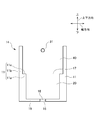
- FIG. 2 is a cross-sectional view of the outer container 14 in the width direction.
- the outer container 14 has a box shape with an open upper surface, a pair of lateral wall portions 11 facing each other and extending in the longitudinal direction, and a pair of end wall portions 12 (shown in FIG. 1) facing each other and extending in the width direction.
- a box-shaped member having a bottom portion 19 and having an open top.
- the lateral wall portion 11 is longer than the end wall portion 12.
- the direction in which the lateral wall portion 11 extends is referred to as a longitudinal direction
- the direction in which the end wall portion 12 extends is referred to as a width direction.
- the lateral wall portion 11 of the outer container 14 has an inner region 11a and an outer region 11b.
- the inner region 11a is lower than the outer region 11b, and a step portion 11c is formed at the upper end of the inner region 11a.
- the end wall portion 12 also has an inner region and an outer region.
- the heights of the inner region and the outer region of the end wall portion 12 are the same as the heights of the inner region 11a and the outer region 11b of the lateral wall portion 11, and stepped portions are formed at the same positions.
- the plate-like mesh member 17 is arranged in such a manner that the edge is held by the step 11c of the lateral wall 11 and the step of the end wall 12.
- the mesh member 17 has substantially the same shape as the rectangular shape defined by the inner wall of the outer region 11 b of the lateral wall portion 11 and the outer region of the end wall portion 12.
- the mesh member 17 separates the internal space of the outer container 14 into two spaces, a lower space and an upper space. However, since it has a mesh shape, a nutrient solution described later can flow from the upper space to the lower space.
- the upper space is a container placement unit 40 in which a culture soil storage container 51 (to be described later) of the planting unit 50 is placed, and the lower space is a culture solution storage unit 20 that stores a nutrient solution sprayed on plants.
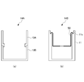
- FIG. 3 is a view showing a modified example of the outer container 14.
- FIG. 3A shows an outer container 14A of the first modification
- FIG. 3B shows an outer container 14B of the second modification.
- the outer container 14 may be separable into two upper containers 10A and a lower container 10B.
- the step part 11c provided in the inside of the exterior container 14 is provided upwards, the edge part is provided in the cultivation soil container 51, and the edge part is hung on the step part 11c. There may be.
- the container placement part 40 is open at the top, and the soil storage container 51 can be placed on the mesh member 17.
- the culture solution storage unit 20 is located below the container placement unit 40.
- a drain hole 15 is provided in the bottom 19 of the culture medium reservoir 20, and a plug 16 that can be opened and closed is attached to the hole 15.
- the culture solution storage unit 20 stores water containing nutrients.
- the outer container 14 further includes a liquid feed pump 30 disposed inside the container placement portion 40 and a watering line for sprinkling the nutrient solution fed by the liquid feed pump 30 to the container placement portion 40.
- a watering pipe 31 There is a watering pipe 31.
- the liquid feed pump 30 is preferably, for example, an amphibious pump with low noise.
- the liquid feeding pump 30 is arrange
- a water spray pipe 31 extends from the liquid feed pump 30 as a liquid feed line.
- the sprinkling pipe 31 extends upward on the side surface of the outer container 14, and further extends horizontally on the upper portion of the container placement portion 40.
- a plurality of sprinkling holes 31 a are provided in the lower part of the portion of the sprinkling pipe 31 that passes over the container placement portion 40.
- suspension frame 13 A suspension frame 13 is attached to the outer container 14.
- the suspension frame 13 is for holding the upper end of a climbing material 52 described later.
- the suspension frame 13 is disposed at an end portion in the longitudinal direction (front and rear) of the outer container 14, and spans between two strut portions 13 a extending upward from the outer container 14 and upper ends of the two strut portions 13 a. Extended portion 13b.
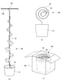
- FIG. 4 is a diagram illustrating the planting unit 50.
- the planting part 50 is a culture soil container 51 in which the culture soil 54 is stored, a climbing material 52 in which the lower end is inserted and held in the culture soil 54, and an attachment part attached to the upper end of the climbing material 52. And a certain hook 53.
- FIG.4 (a) shows the state by which the hook 53 of the planting part 50 is attached to the extension part 13b.
- the cultivation soil container 51 accommodates cultivation soil, and a plant is planted in the cultivation soil.
- the cultivated soil is, for example, inorganic vermiculite, pearlite, rock wool, hydroball, sponge or the like for hydroponics, and is lighter than soil.
- the plant planted is a vine plant.
- the climbing material 52 is manufactured by a wire, and a hook-shaped attachment portion 53 that can be detachably hooked on the extension portion 13b of the suspension frame 13 is provided at the tip thereof.
- the attachment portion 53 is not limited to a hook shape, and may be a clip shape. In the case of a clip, the climbing material 52 can be attached to the extending portion 13b in a more fixed state by gripping a predetermined portion of the extending portion 13b.
- the climbing material 52 can be bent and can be wound in a spiral shape, a spider shape, a circular shape, a spiral shape, or the like.
- FIG.4 (b) is a figure which shows the state which wound the climbing material 52 in spiral shape
- (c) is the box 60, such as corrugated cardboard, in the planting part 50 of the state in which the climbing material 52 was wound spirally. It is in a state of being stored in.
- the climbing material 52 can be partially or wholly manufactured by a spring, or can be manufactured by an elastic member. In this case, the length can be adjusted, and the suspension frame 13 can be adjusted while the spring is slightly pulled. If it is made to mount
- a nutrient solution necessary for plant growth is placed in the culture solution reservoir 20 and the mesh member 17 is disposed.
- a plurality of planting parts 50 in which cultivated soil and a plant that hangs on the cultivated soil are planted are placed in the container placement part 40.
- the climbing material 52 is suspended from the suspension frame 13 by hooking the attachment portions 53 of the climbing material 52 of the planting unit 50 to the extending portions 13 b of the suspension frame 13.
- the liquid feed pump 30 is operated. Although the time for operating the liquid feeding pump 30 varies depending on the season, for example, once a day is about 5 minutes, and the time can be managed by a timer or the like.
- the liquid feeding pump 30 is operated, the nutrient solution is sent to the upper part through the watering pipe 31, and is sprinkled into the soil through the watering holes 31a.
- the nutrient solution supplied to the container placement unit 40 is absorbed by the soil.
- the nutrient solution that has not been absorbed flows out into the culture solution reservoir 20.
- the plant planted in the cultivating soil container 51 of the planting part 50 grows, it winds around the climbing material 52 and extends upward.
- the poorly growing planting part 50 is replaced. be able to.
- the attachment portion 53 attached to the upper part of the climbing material 52 of the planting part 50 in which the poorly grown plant is planted is removed from the extending part 13b of the suspension frame 13 of the fixed part 10.
- the attachment portion 53 has a hook shape and can be easily removed.
- the climbing material 52 is made of wire and can be bent, it can be made compact by winding it in a spiral shape as shown in FIG. 4 (b).
- the planting part 50 in a state in which the climbing material 52 is wound in a spiral shape is compact, so that the plant goes out for replacement.
- the leasing company can store the product in a box such as cardboard and take it home, which facilitates transportation. At this time, since it becomes compact, courier transportation is also possible.
- the root soil that is rooted in the soil storage container 51 is a well-drained soil for hydroponics.
- soil such as inorganic vermiculite, perlite, rock wool, hydroball, sponge, It is lighter than that. Therefore, compared with the conventional exchange for every natural soil, the weight can be significantly reduced and the transportation becomes easy.
- the planting part 50 in which the plant of the good growth state carried in the compact and the state was planted similarly is arrange
- the attachment part 53 of the climbing material 52 of the planting part 50 is attached to the extending part 13b of the suspension frame 13. As mentioned above, according to this embodiment, the planting part 50 can be replaced
- the plurality of planting parts 50 can be individually replaced, in the case of replacement of a plant in which a continuous cropping failure occurs, it is possible to cope with it by replacing the culture medium.
- the wall surface greening unit 1 in which the exterior container 14 and the suspension frame 13 are integrated can be provided.
- the nutrient solution is automatically sent by the feeding pump 30, it is possible to save the user from sprinkling water and supplying the nutrient solution. In addition, drying and growth failure due to forgetting to supply nutrient solution do not occur.
- the nutrient solution is not poured, and the nutrient solution that has not been absorbed by the culture medium flows out to the culture solution reservoir 20. Since the nutrient solution stored in the culture solution storage unit 20 is again sent to the culture medium by the solution feeding pump 30, the nutrient solution is not wasted. Therefore, there is little possibility of environmental pollution.
- growth has deteriorated due to environmental conditions, etc., it can be collected (purchased) at the time of purchase of a new cartridge and re-sold in a place with good environmental conditions such as a greenhouse and then sold again.
Landscapes
- Life Sciences & Earth Sciences (AREA)
- Environmental Sciences (AREA)
- Engineering & Computer Science (AREA)
- Water Supply & Treatment (AREA)
- Supports For Plants (AREA)
- Cultivation Of Plants (AREA)
- Cultivation Receptacles Or Flower-Pots, Or Pots For Seedlings (AREA)
Abstract
植物の交換が容易に可能な壁面緑化ユニットを提供する。 本発明の壁面緑化ユニット1は、外装容器14、及び、前記外装容器14に取り付けられ且つ前記外装容器14の上方を延びる延在部13bを有する懸架フレーム13、を含む固設部10と、培土54が収納され且つ前記外装容器14の内部に配置可能な培土収容容器51、前記培土収容容器51から延びる登攀材52、及び、前記登攀材52の上端に取り付けられ且つ前記延在部13bに着脱可能な取付部、を含む植栽部50と、を備え、前記植栽部50が、前記固設部10に対して着脱可能である。
Description
本発明は、壁面緑化ユニットに関する。
近年、壁面緑化は、都市部で問題になっているヒートアイランド現象の緩和策、省エネ対策の他にも多くの効果が期待できる。
従来、土壌収納部、潅水装置、及び植栽された植物を誘引し支持する装置としての登攀材を揃えた壁面緑化装置が存在する。土壌収納部は主としてつる性植物の成長に適した根の部分の環境を整えるものである。雨水を主として潅水する潅水装置は、給水を制御できる弁装置を備える。登攀材は両端が取付け具により他の物へ取り付け可能とされている。
また、従来より、観葉植物のリース事業が行われている。リース事業では,定期的に植物を交換し、環境条件の整った温室で再生(活性化)して再度、顧客に戻すことが行われている。
従来、土壌収納部、潅水装置、及び植栽された植物を誘引し支持する装置としての登攀材を揃えた壁面緑化装置が存在する。土壌収納部は主としてつる性植物の成長に適した根の部分の環境を整えるものである。雨水を主として潅水する潅水装置は、給水を制御できる弁装置を備える。登攀材は両端が取付け具により他の物へ取り付け可能とされている。
また、従来より、観葉植物のリース事業が行われている。リース事業では,定期的に植物を交換し、環境条件の整った温室で再生(活性化)して再度、顧客に戻すことが行われている。
従来技術の壁面緑化装置における植物は、所定の場所に固定設置されるものであり、リース事業等の業者が植物を交換することを前提としていない。
また、壁面緑化以外において、植物のリース事業は行われているが、この場合、植物の交換の際、鉢やプランタの土が重く、多大な労力が必要となっていた。
また、壁面緑化以外において、植物のリース事業は行われているが、この場合、植物の交換の際、鉢やプランタの土が重く、多大な労力が必要となっていた。
本発明は、植物の交換が容易に可能な壁面緑化ユニットを提供することを目的とする。
(1)本発明は、外装容器、及び、前記外装容器に取り付けられ且つ前記外装容器の上方を延びる延在部を有する懸架フレーム、を含む固設部と、培土が収納され且つ前記外装容器の内部に配置可能な培土収容容器、前記培土収容容器から延びる登攀材、及び、前記登攀材の上端に取り付けられ且つ前記延在部に着脱可能な取付部、を含む植栽部と、を備え、前記植栽部が、前記固設部に対して着脱可能である壁面緑化ユニットである。
(2)前記登攀材は、湾曲可能な部材で製造されていることが好ましい。
(3)前記外装容器は、前記培土収容容器を配置する容器配置部と、前記容器配置部の下部に設けられた培養液貯留部と、を備え、前記培養液貯留部から前記容器配置部に延びるとともに、前記容器配置部に配置された前記培土収容容器に養液を散布する送液ラインと、前記送液ラインに前記養液を送液する送液ポンプと、を備えることが好ましい。
本発明によれば、植物の交換が容易に可能な壁面緑化ユニットを提供することができる。
以下、図面を参照しながら、本発明の実施形態の壁面緑化ユニット1について説明する。図1は、本発明の実施形態の壁面緑化ユニット1を長手方向からみた概略図である。図示するように、壁面緑化ユニット1は、固設部10と、培土収容容器51及び登攀材52を含むと植栽部50と、を備える。
(固設部10)
固設部10は、所望の場所に固定設置される部分である。固設部10は、複数の植栽部50を収納可能な外装容器14と、外装容器14の前後(図1における左右)において外装容器14から上方に延びる2本の支柱部13a及び2本の支柱部13aの上端の間に架け渡された延在部13bを含む懸架フレーム13と、を備える。
固設部10は、所望の場所に固定設置される部分である。固設部10は、複数の植栽部50を収納可能な外装容器14と、外装容器14の前後(図1における左右)において外装容器14から上方に延びる2本の支柱部13a及び2本の支柱部13aの上端の間に架け渡された延在部13bを含む懸架フレーム13と、を備える。
図2は、外装容器14の幅方向の断面図である。外装容器14は、上面が開口した箱型であり、互いに対向するとともに長手方向に延びる一対の横壁部11と、互いに対向するとともに幅方向に延びる一対の端壁部12(図1に示す)と、底部19とを有する、上部が開口した箱型部材である。実施形態で横壁部11は、端壁部12より長尺となっている。以下、横壁部11が延びる方向を長手方向、端壁部12が延びる方向を幅方向という。
図2に示すように、外装容器14の横壁部11は、内側領域11aと外側領域11bとを有する。内側領域11aの高さは外側領域11bよりも低く、内側領域11aの上端には、段部11cが形成されている。
なお、図示しないが、端壁部12も内側領域と外側領域とを有する。端壁部12の内側領域と外側領域の高さは、横壁部11の内側領域11aと外側領域11bとの高さと同じであり、同位置に段部が形成されている。
なお、図示しないが、端壁部12も内側領域と外側領域とを有する。端壁部12の内側領域と外側領域の高さは、横壁部11の内側領域11aと外側領域11bとの高さと同じであり、同位置に段部が形成されている。
横壁部11の段部11cと端壁部12の段部とに縁部が保持される形で、板状のメッシュ部材17が配置されている。メッシュ部材17は、横壁部11の外側領域11bと端壁部12の外側領域との内壁で画される矩形形状と略同形である。メッシュ部材17によって、外装容器14の内部空間が、下部空間と上部空間との2つの空間とに分離されている。ただし、メッシュ状であるため上部空間から下部空間へ後述の養液は流れ出ることができる。上部空間は、植栽部50の後述の培土収容容器51を配置する容器配置部40であり、下部空間は、植物に散布される養液を貯留する培養液貯留部20である。
本実施形態では、このように横壁部11に設けた段部にメッシュ部材17を配置することより外装容器14の内部空間を分離している。ただし、これに限定されない。図3は、外装容器14の変形例を示した図である。図3(a)は第1変形例の外装容器14A、図3(b)は第2変形例の外装容器14Bを示す。内部空間の分離方法としては、図3(a)に示すように外装容器14を2つの上容器10Aと下容器10Bとに分離可能としてもよい。また、図3(b)に示すように、外装容器14の内部に設ける段部11cを上方に設け、培土収容容器51に縁部を設けて、その縁部をその段部11cに懸けるものであってもよい。
(容器配置部40)
図1及び図2の本実施形態に戻り、容器配置部40について説明する。容器配置部40は、上部が開放しており、メッシュ部材17上に、培土収容容器51を配置することができる。
図1及び図2の本実施形態に戻り、容器配置部40について説明する。容器配置部40は、上部が開放しており、メッシュ部材17上に、培土収容容器51を配置することができる。
(培養液貯留部20)
培養液貯留部20は、容器配置部40の下部に位置する。培養液貯留部20の底部19には、水抜き用の穴15が設けられ、その穴15には開閉可能な栓16が取り付けられている。培養液貯留部20には、養分を含む水が貯留されている。
培養液貯留部20は、容器配置部40の下部に位置する。培養液貯留部20の底部19には、水抜き用の穴15が設けられ、その穴15には開閉可能な栓16が取り付けられている。培養液貯留部20には、養分を含む水が貯留されている。
(送液ポンプ30)
外装容器14は、さらに、図1に示すように容器配置部40の内部に配置された送液ポンプ30と、送液ポンプ30により送り出される養液を、容器配置部40に散水する散水ラインである散水パイプ31と、を備える。送液ポンプ30は、例えば水陸両用のポンプで低騒音のものが好ましい。
なお、本実施形態では、送液ポンプ30は培養液貯留部20の内部に配置されているが、これに限らず、培養液貯留部20の外部に配置してもよい。
外装容器14は、さらに、図1に示すように容器配置部40の内部に配置された送液ポンプ30と、送液ポンプ30により送り出される養液を、容器配置部40に散水する散水ラインである散水パイプ31と、を備える。送液ポンプ30は、例えば水陸両用のポンプで低騒音のものが好ましい。
なお、本実施形態では、送液ポンプ30は培養液貯留部20の内部に配置されているが、これに限らず、培養液貯留部20の外部に配置してもよい。
(散水パイプ31)
送液ポンプ30から、送液ラインとして散水パイプ31が延びている。散水パイプ31は、外装容器14の側面を上方に延び、さらに、容器配置部40の上部を水平に延びる。散水パイプ31の容器配置部40の上を通る部分の下部には、複数の散水穴31aが設けられている。
送液ポンプ30から、送液ラインとして散水パイプ31が延びている。散水パイプ31は、外装容器14の側面を上方に延び、さらに、容器配置部40の上部を水平に延びる。散水パイプ31の容器配置部40の上を通る部分の下部には、複数の散水穴31aが設けられている。
(懸架フレーム13)
外装容器14には、懸架フレーム13が取り付けられている。懸架フレーム13は、後述の登攀材52の上端を保持するためのものである。懸架フレーム13は、外装容器14の長手方向(前後)の端部に配置され、外装容器14より上方に延びる2本の支柱部13aと、その2本の支柱部13aの上端の間に架け渡された延在部13bと、を備える。
外装容器14には、懸架フレーム13が取り付けられている。懸架フレーム13は、後述の登攀材52の上端を保持するためのものである。懸架フレーム13は、外装容器14の長手方向(前後)の端部に配置され、外装容器14より上方に延びる2本の支柱部13aと、その2本の支柱部13aの上端の間に架け渡された延在部13bと、を備える。
(植栽部50)
図4は植栽部50を説明する図である。図示するように植栽部50は、培土54が収納された培土収容容器51と、培土54に下端が挿入されて保持された登攀材52と、登攀材52の上端に取り付けられた取付部であるフック53と、を備える。
図4は植栽部50を説明する図である。図示するように植栽部50は、培土54が収納された培土収容容器51と、培土54に下端が挿入されて保持された登攀材52と、登攀材52の上端に取り付けられた取付部であるフック53と、を備える。
(培土収容容器51)
図4(a)は、植栽部50のフック53が、延在部13bに取り付けられている状態を示す。培土収容容器51は、培土を収容し、その培土には植物が植え込まれている。本実施形態で培土は、水耕栽培用の、例えば無機物のバーミキュライト、パーライト、ロックウール、ハイドロボール、スポンジ等であり、土に比べて軽量である。また、植え込まれた植物は、つる性の植物である。
図4(a)は、植栽部50のフック53が、延在部13bに取り付けられている状態を示す。培土収容容器51は、培土を収容し、その培土には植物が植え込まれている。本実施形態で培土は、水耕栽培用の、例えば無機物のバーミキュライト、パーライト、ロックウール、ハイドロボール、スポンジ等であり、土に比べて軽量である。また、植え込まれた植物は、つる性の植物である。
(登攀材52)
登攀材52は、ワイヤーで製造され、その先端に、懸架フレーム13の延在部13bに着脱可能に引っ掛けることが可能なフック状の取付部53が設けられている。取付部53を懸架フレーム13に引っ掛けることにより、登攀材52の上端が懸架フレーム13に保持され、登攀材52を懸架フレーム13に懸架することができる。
なお、取付部53はフック状に限らず、クリップ状でもよい。クリップ状の場合、延在部13bの所定の部位を把持することにより、より固定された状態で登攀材52を延在部13bに取り付けることができる。
登攀材52は、ワイヤーで製造され、その先端に、懸架フレーム13の延在部13bに着脱可能に引っ掛けることが可能なフック状の取付部53が設けられている。取付部53を懸架フレーム13に引っ掛けることにより、登攀材52の上端が懸架フレーム13に保持され、登攀材52を懸架フレーム13に懸架することができる。
なお、取付部53はフック状に限らず、クリップ状でもよい。クリップ状の場合、延在部13bの所定の部位を把持することにより、より固定された状態で登攀材52を延在部13bに取り付けることができる。
登攀材52は、湾曲可能であり、渦巻き状、とぐろ状、円形状又はらせん状等に巻くことができる。図4(b)は、登攀材52を渦巻き状に巻いた状態を示す図であり、(c)は登攀材52が渦巻き状に巻かれた状態の植栽部50を、段ボール等の箱60に収納した状態である。
また登攀材52は、例えば、部分的又は全体をバネで製造し、又は弾性部材で製造することもでき、その場合、長さ調節が可能となり、バネがわずかに引っ張られた状態で懸架フレーム13に装着されるようにすると、登攀材52を撓ませることなく、懸架フレーム13に取り付けることができる。
また登攀材52は、例えば、部分的又は全体をバネで製造し、又は弾性部材で製造することもでき、その場合、長さ調節が可能となり、バネがわずかに引っ張られた状態で懸架フレーム13に装着されるようにすると、登攀材52を撓ませることなく、懸架フレーム13に取り付けることができる。
(使用方法)
培養液貯留部20の内部に、植物の育成に必要な養液を入れ、メッシュ部材17を配置する。
容器配置部40に、培土及びその培土につる性の植物が植え込まれた複数の植栽部50を配置する。植栽部50の登攀材52の取付部53を、それぞれ懸架フレーム13の延在部13bに引っ掛けることにより、登攀材52を懸架フレーム13に懸架する。
培養液貯留部20の内部に、植物の育成に必要な養液を入れ、メッシュ部材17を配置する。
容器配置部40に、培土及びその培土につる性の植物が植え込まれた複数の植栽部50を配置する。植栽部50の登攀材52の取付部53を、それぞれ懸架フレーム13の延在部13bに引っ掛けることにより、登攀材52を懸架フレーム13に懸架する。
送液ポンプ30を作動させる。送液ポンプ30を作動させる時間は、季節等によって異なるが、例えば1日1回、5分程度とし、その時間はタイマー等で管理可能である。
送液ポンプ30が作動されると、養液は、散水パイプ31を伝わって上部へと送出され、散水穴31aより培土へ散水される。
送液ポンプ30が作動されると、養液は、散水パイプ31を伝わって上部へと送出され、散水穴31aより培土へ散水される。
容器配置部40に供給された養液は、培土によって吸収される。吸収されなかった養液は培養液貯留部20に流出する。
植栽部50の培土収容容器51に植え込まれた植物が育っていくと、登攀材52に巻き付いて、上方に延びていく。
植栽部50の培土収容容器51に植え込まれた植物が育っていくと、登攀材52に巻き付いて、上方に延びていく。
本実施形態では、例えば壁面緑化ユニットの複数の植栽部50のうちのいくつかの植栽部50に植え込まれた植物の発育状態が良好でない場合、発育不良の植栽部50を交換することができる。
交換は、まず、発育不良の植物が植えられている植栽部50の登攀材52の上部に取り付けられた取付部53を固設部10の懸架フレーム13の延在部13bから外す。このとき、取付部53はフック状であるので取り外しが容易である。
登攀材52は、ワイヤーで製造されており、湾曲可能であるので、図4(b)に示すように、渦巻き状に巻いてコンパクトにすることができる。例えば、植物がリース業者からのリースされているものである場合、(c)に示すように、登攀材52が渦巻き状に巻かれた状態の植栽部50はコンパクトであるので、交換に出向いたリース業者は、段ボール等の箱に収納して持ち帰ることができ、輸送が容易になる。この際、コンパクトになるので、宅配便輸送も可能となる。
さらに、本実施形態では、培土収容容器51内において根のはる培土は、水はけのよい水耕栽培用の培土であり、例えば無機物のバーミキュライト、パーライト、ロックウール、ハイドロボール、スポンジ等の、土に比べて軽量なものである。したがって、従来のような、天然の土ごとの交換と比較すると大幅な軽量化が可能となり、運搬が容易になる。
そして、同様にコンパクト且な状態で運び込まれた発育のよい状態の植物が植えこまれた植栽部50を、発育不良の植物が植えこまれた植栽部50が配置されていた位置に配置する。そして、その植栽部50の登攀材52の取付部53を懸架フレーム13の延在部13bに取り付ける。
以上、本実施形態によると、植栽部50を容易に交換することができる。
以上、本実施形態によると、植栽部50を容易に交換することができる。
また、本実施形態では、複数の植栽部50を個々に交換可能としたので連作障害が発生する植物の交換の場合、培養液を全取替することにより対応が可能となる。
外装容器14に懸架フレーム13が装着されているので、外装容器14と懸架フレーム13とが一体となった壁面緑化ユニット1を提供することができる。
養液は送液ポンプ30により自動で送られるので、使用者の散水及び養液の供給の手間を省くことができる。また、養液の供給忘れによる乾燥や発育不全が生じることがない。
養液は、かけ流しでなく、培土により吸収されなかった養液は、培養液貯留部20に流れ出る。培養液貯留部20に貯留された養液は、再度、送液ポンプ30で培土へと送られるので、養液が無駄になることがない。ゆえに、環境汚染等の可能性が少ない。
リース事業以外にも,固設部10のみをまず顧客に低価格で販売し、カートリッジ状に成形した各種植物を別途販売する手法が考えられる。この場合、各種植物は軽量且つコンパクトであるので、宅配便により提供可能である。
環境条件等により生育が悪化した場合は新規カートリッジの購入時に回収(買取)し、温室など環境条件の良好な場所で再生した上で、再度販売することも可能である。
1 壁面緑化ユニット
2 支柱部
10 固設部
11 横壁部
11a 内側領域
11b 外側領域
11c 段部
12 端壁部
13 懸架フレーム
13a 支柱部
13b 延在部
14 外装容器
17 メッシュ部材
20 培養液貯留部
30 送液ポンプ
31 散水パイプ
31a 散水穴
40 容器配置部
50 植栽部
51 培土収容容器
52 登攀材
53 取付部
54 培土
2 支柱部
10 固設部
11 横壁部
11a 内側領域
11b 外側領域
11c 段部
12 端壁部
13 懸架フレーム
13a 支柱部
13b 延在部
14 外装容器
17 メッシュ部材
20 培養液貯留部
30 送液ポンプ
31 散水パイプ
31a 散水穴
40 容器配置部
50 植栽部
51 培土収容容器
52 登攀材
53 取付部
54 培土
Claims (3)
- 外装容器、及び、前記外装容器に取り付けられ且つ前記外装容器の上方を延びる延在部を有する懸架フレーム、を含む固設部と、
培土が収納され且つ前記外装容器の内部に配置可能な培土収容容器、前記培土収容容器から延びる登攀材、及び、前記登攀材の上端に取り付けられ且つ前記延在部に着脱可能な取付部、を含む植栽部と、を備え、
前記植栽部が、前記固設部に対して着脱可能である壁面緑化ユニット。 - 前記登攀材は、湾曲可能な部材で製造されている
請求項1に記載の壁面緑化ユニット。 - 前記外装容器は、
前記培土収容容器を配置する容器配置部と、
前記容器配置部の下部に設けられた培養液貯留部と、を備え、
前記培養液貯留部から前記容器配置部に延びるとともに、前記容器配置部に配置された前記培土収容容器に養液を散布する送液ラインと、
前記送液ラインに前記養液を送液する送液ポンプと、
を備える請求項1又は2に記載の壁面緑化ユニット。
Priority Applications (2)
| Application Number | Priority Date | Filing Date | Title |
|---|---|---|---|
| JP2017535852A JP6229823B1 (ja) | 2017-01-10 | 2017-01-10 | 壁面緑化ユニット |
| PCT/JP2017/000490 WO2018131072A1 (ja) | 2017-01-10 | 2017-01-10 | 壁面緑化ユニット |
Applications Claiming Priority (1)
| Application Number | Priority Date | Filing Date | Title |
|---|---|---|---|
| PCT/JP2017/000490 WO2018131072A1 (ja) | 2017-01-10 | 2017-01-10 | 壁面緑化ユニット |
Publications (1)
| Publication Number | Publication Date |
|---|---|
| WO2018131072A1 true WO2018131072A1 (ja) | 2018-07-19 |
Family
ID=60321077
Family Applications (1)
| Application Number | Title | Priority Date | Filing Date |
|---|---|---|---|
| PCT/JP2017/000490 Ceased WO2018131072A1 (ja) | 2017-01-10 | 2017-01-10 | 壁面緑化ユニット |
Country Status (2)
| Country | Link |
|---|---|
| JP (1) | JP6229823B1 (ja) |
| WO (1) | WO2018131072A1 (ja) |
Families Citing this family (1)
| Publication number | Priority date | Publication date | Assignee | Title |
|---|---|---|---|---|
| CN112568004A (zh) * | 2019-03-12 | 2021-03-30 | 丽水景诚科技有限公司 | 一种高层建筑外墙攀援植物绿化系统及其控制方法 |
Citations (5)
| Publication number | Priority date | Publication date | Assignee | Title |
|---|---|---|---|---|
| JP2000188960A (ja) * | 1998-12-25 | 2000-07-11 | Gifu Plast Ind Co Ltd | パネル付きプランタ |
| JP2001269064A (ja) * | 2000-03-27 | 2001-10-02 | Iseki & Co Ltd | 栽培施設における作物茎部の誘引装置 |
| JP2011050340A (ja) * | 2009-09-03 | 2011-03-17 | Sumitomo Mitsui Construction Co Ltd | つる植物育成装置 |
| JP2013106584A (ja) * | 2011-11-22 | 2013-06-06 | Shinichi Fukada | 植物栽培法及び植物栽培装置 |
| US20130283684A1 (en) * | 2012-03-23 | 2013-10-31 | Pat King | Portable plant support system |
-
2017
- 2017-01-10 WO PCT/JP2017/000490 patent/WO2018131072A1/ja not_active Ceased
- 2017-01-10 JP JP2017535852A patent/JP6229823B1/ja active Active
Patent Citations (5)
| Publication number | Priority date | Publication date | Assignee | Title |
|---|---|---|---|---|
| JP2000188960A (ja) * | 1998-12-25 | 2000-07-11 | Gifu Plast Ind Co Ltd | パネル付きプランタ |
| JP2001269064A (ja) * | 2000-03-27 | 2001-10-02 | Iseki & Co Ltd | 栽培施設における作物茎部の誘引装置 |
| JP2011050340A (ja) * | 2009-09-03 | 2011-03-17 | Sumitomo Mitsui Construction Co Ltd | つる植物育成装置 |
| JP2013106584A (ja) * | 2011-11-22 | 2013-06-06 | Shinichi Fukada | 植物栽培法及び植物栽培装置 |
| US20130283684A1 (en) * | 2012-03-23 | 2013-10-31 | Pat King | Portable plant support system |
Also Published As
| Publication number | Publication date |
|---|---|
| JPWO2018131072A1 (ja) | 2019-01-17 |
| JP6229823B1 (ja) | 2017-11-15 |
Similar Documents
| Publication | Publication Date | Title |
|---|---|---|
| AU2008337673B2 (en) | Live plant box | |
| US20110219689A1 (en) | Botanical Arrangement and Display Apparatus | |
| KR101227836B1 (ko) | 수경화분 및 수경재배장치 | |
| JP2018516094A (ja) | 垂直水耕園芸システム | |
| US20080209805A1 (en) | Wall Planted with Vegetation and Constituent Elements | |
| CN110326460A (zh) | 一种用于幼苗培育的花木养护架 | |
| JP6229823B1 (ja) | 壁面緑化ユニット | |
| CN205005581U (zh) | 一种阳台植物种植架 | |
| JP4968697B2 (ja) | 緑化カーテンウォール | |
| CN203136721U (zh) | 叠槽式立体无土栽培设施 | |
| JP3827680B2 (ja) | 花卉植栽構造 | |
| JP4936176B2 (ja) | 壁面緑化ユニット | |
| JP3774733B2 (ja) | 植物育成用のポット及び植物育成装置 | |
| JP7160515B2 (ja) | 植物登攀装置 | |
| KR101336361B1 (ko) | 식물 재배용 수분 공급기 | |
| JP5062560B2 (ja) | 壁面緑化ユニット | |
| CN204540092U (zh) | 一种智能墙面垂直绿化种植栽盆 | |
| CN119344195B (zh) | 一种适用于花卉种植的滴灌装置 | |
| JP3187955U (ja) | つる性植物による緑化部材とこの緑化部材を用いたグリーンカーテン | |
| CN215122752U (zh) | 绿化培养基卷材及加湿装置 | |
| CN210610587U (zh) | 一种多功能林业苗木移栽装置 | |
| JP5899362B1 (ja) | 植木鉢 | |
| CN209572642U (zh) | 一种遮荫用双层立体组合花架 | |
| JP2009207365A (ja) | 農業用ハウス | |
| JP3124166U (ja) | プランター |
Legal Events
| Date | Code | Title | Description |
|---|---|---|---|
| ENP | Entry into the national phase |
Ref document number: 2017535852 Country of ref document: JP Kind code of ref document: A |
|
| 121 | Ep: the epo has been informed by wipo that ep was designated in this application |
Ref document number: 17891505 Country of ref document: EP Kind code of ref document: A1 |
|
| NENP | Non-entry into the national phase |
Ref country code: DE |
|
| 122 | Ep: pct application non-entry in european phase |
Ref document number: 17891505 Country of ref document: EP Kind code of ref document: A1 |