WO2018131062A1 - Travel path recognition device and travel path recognition method - Google Patents
Travel path recognition device and travel path recognition method Download PDFInfo
- Publication number
- WO2018131062A1 WO2018131062A1 PCT/JP2017/000405 JP2017000405W WO2018131062A1 WO 2018131062 A1 WO2018131062 A1 WO 2018131062A1 JP 2017000405 W JP2017000405 W JP 2017000405W WO 2018131062 A1 WO2018131062 A1 WO 2018131062A1
- Authority
- WO
- WIPO (PCT)
- Prior art keywords
- vehicle
- travel path
- distance
- lane
- lane line
- Prior art date
Links
- 238000000034 method Methods 0.000 title claims description 30
- 238000005516 engineering process Methods 0.000 abstract description 2
- 239000003550 marker Substances 0.000 abstract 4
- 238000001514 detection method Methods 0.000 description 88
- 230000006399 behavior Effects 0.000 description 36
- 230000008569 process Effects 0.000 description 19
- 230000006870 function Effects 0.000 description 16
- 230000008859 change Effects 0.000 description 14
- 239000013256 coordination polymer Substances 0.000 description 10
- 238000010586 diagram Methods 0.000 description 8
- 238000004364 calculation method Methods 0.000 description 7
- 238000003384 imaging method Methods 0.000 description 6
- 238000004891 communication Methods 0.000 description 3
- 230000004048 modification Effects 0.000 description 3
- 238000012986 modification Methods 0.000 description 3
- 238000006243 chemical reaction Methods 0.000 description 2
- 230000004069 differentiation Effects 0.000 description 2
- 230000010354 integration Effects 0.000 description 2
- 230000002093 peripheral effect Effects 0.000 description 2
- 241001290864 Schoenoplectus Species 0.000 description 1
- 230000001133 acceleration Effects 0.000 description 1
- 238000009825 accumulation Methods 0.000 description 1
- 239000002131 composite material Substances 0.000 description 1
- 230000006866 deterioration Effects 0.000 description 1
- 239000000284 extract Substances 0.000 description 1
- 238000013213 extrapolation Methods 0.000 description 1
- 230000003287 optical effect Effects 0.000 description 1
- 238000005192 partition Methods 0.000 description 1
- 230000004044 response Effects 0.000 description 1
- 239000004065 semiconductor Substances 0.000 description 1
Images


Classifications
-
- B—PERFORMING OPERATIONS; TRANSPORTING
- B60—VEHICLES IN GENERAL
- B60W—CONJOINT CONTROL OF VEHICLE SUB-UNITS OF DIFFERENT TYPE OR DIFFERENT FUNCTION; CONTROL SYSTEMS SPECIALLY ADAPTED FOR HYBRID VEHICLES; ROAD VEHICLE DRIVE CONTROL SYSTEMS FOR PURPOSES NOT RELATED TO THE CONTROL OF A PARTICULAR SUB-UNIT
- B60W30/00—Purposes of road vehicle drive control systems not related to the control of a particular sub-unit, e.g. of systems using conjoint control of vehicle sub-units, or advanced driver assistance systems for ensuring comfort, stability and safety or drive control systems for propelling or retarding the vehicle
- B60W30/10—Path keeping
- B60W30/12—Lane keeping
-
- B—PERFORMING OPERATIONS; TRANSPORTING
- B60—VEHICLES IN GENERAL
- B60W—CONJOINT CONTROL OF VEHICLE SUB-UNITS OF DIFFERENT TYPE OR DIFFERENT FUNCTION; CONTROL SYSTEMS SPECIALLY ADAPTED FOR HYBRID VEHICLES; ROAD VEHICLE DRIVE CONTROL SYSTEMS FOR PURPOSES NOT RELATED TO THE CONTROL OF A PARTICULAR SUB-UNIT
- B60W40/00—Estimation or calculation of non-directly measurable driving parameters for road vehicle drive control systems not related to the control of a particular sub unit, e.g. by using mathematical models
- B60W40/02—Estimation or calculation of non-directly measurable driving parameters for road vehicle drive control systems not related to the control of a particular sub unit, e.g. by using mathematical models related to ambient conditions
- B60W40/04—Traffic conditions
-
- B—PERFORMING OPERATIONS; TRANSPORTING
- B60—VEHICLES IN GENERAL
- B60W—CONJOINT CONTROL OF VEHICLE SUB-UNITS OF DIFFERENT TYPE OR DIFFERENT FUNCTION; CONTROL SYSTEMS SPECIALLY ADAPTED FOR HYBRID VEHICLES; ROAD VEHICLE DRIVE CONTROL SYSTEMS FOR PURPOSES NOT RELATED TO THE CONTROL OF A PARTICULAR SUB-UNIT
- B60W40/00—Estimation or calculation of non-directly measurable driving parameters for road vehicle drive control systems not related to the control of a particular sub unit, e.g. by using mathematical models
- B60W40/02—Estimation or calculation of non-directly measurable driving parameters for road vehicle drive control systems not related to the control of a particular sub unit, e.g. by using mathematical models related to ambient conditions
- B60W40/06—Road conditions
-
- G—PHYSICS
- G01—MEASURING; TESTING
- G01C—MEASURING DISTANCES, LEVELS OR BEARINGS; SURVEYING; NAVIGATION; GYROSCOPIC INSTRUMENTS; PHOTOGRAMMETRY OR VIDEOGRAMMETRY
- G01C21/00—Navigation; Navigational instruments not provided for in groups G01C1/00 - G01C19/00
- G01C21/10—Navigation; Navigational instruments not provided for in groups G01C1/00 - G01C19/00 by using measurements of speed or acceleration
- G01C21/12—Navigation; Navigational instruments not provided for in groups G01C1/00 - G01C19/00 by using measurements of speed or acceleration executed aboard the object being navigated; Dead reckoning
- G01C21/14—Navigation; Navigational instruments not provided for in groups G01C1/00 - G01C19/00 by using measurements of speed or acceleration executed aboard the object being navigated; Dead reckoning by recording the course traversed by the object
-
- G—PHYSICS
- G06—COMPUTING; CALCULATING OR COUNTING
- G06T—IMAGE DATA PROCESSING OR GENERATION, IN GENERAL
- G06T7/00—Image analysis
- G06T7/60—Analysis of geometric attributes
-
- G—PHYSICS
- G06—COMPUTING; CALCULATING OR COUNTING
- G06V—IMAGE OR VIDEO RECOGNITION OR UNDERSTANDING
- G06V20/00—Scenes; Scene-specific elements
- G06V20/50—Context or environment of the image
- G06V20/56—Context or environment of the image exterior to a vehicle by using sensors mounted on the vehicle
- G06V20/588—Recognition of the road, e.g. of lane markings; Recognition of the vehicle driving pattern in relation to the road
-
- G—PHYSICS
- G08—SIGNALLING
- G08G—TRAFFIC CONTROL SYSTEMS
- G08G1/00—Traffic control systems for road vehicles
- G08G1/16—Anti-collision systems
-
- B—PERFORMING OPERATIONS; TRANSPORTING
- B60—VEHICLES IN GENERAL
- B60W—CONJOINT CONTROL OF VEHICLE SUB-UNITS OF DIFFERENT TYPE OR DIFFERENT FUNCTION; CONTROL SYSTEMS SPECIALLY ADAPTED FOR HYBRID VEHICLES; ROAD VEHICLE DRIVE CONTROL SYSTEMS FOR PURPOSES NOT RELATED TO THE CONTROL OF A PARTICULAR SUB-UNIT
- B60W2420/00—Indexing codes relating to the type of sensors based on the principle of their operation
- B60W2420/40—Photo or light sensitive means, e.g. infrared sensors
- B60W2420/403—Image sensing, e.g. optical camera
-
- B—PERFORMING OPERATIONS; TRANSPORTING
- B60—VEHICLES IN GENERAL
- B60W—CONJOINT CONTROL OF VEHICLE SUB-UNITS OF DIFFERENT TYPE OR DIFFERENT FUNCTION; CONTROL SYSTEMS SPECIALLY ADAPTED FOR HYBRID VEHICLES; ROAD VEHICLE DRIVE CONTROL SYSTEMS FOR PURPOSES NOT RELATED TO THE CONTROL OF A PARTICULAR SUB-UNIT
- B60W2552/00—Input parameters relating to infrastructure
- B60W2552/30—Road curve radius
-
- B—PERFORMING OPERATIONS; TRANSPORTING
- B60—VEHICLES IN GENERAL
- B60W—CONJOINT CONTROL OF VEHICLE SUB-UNITS OF DIFFERENT TYPE OR DIFFERENT FUNCTION; CONTROL SYSTEMS SPECIALLY ADAPTED FOR HYBRID VEHICLES; ROAD VEHICLE DRIVE CONTROL SYSTEMS FOR PURPOSES NOT RELATED TO THE CONTROL OF A PARTICULAR SUB-UNIT
- B60W2552/00—Input parameters relating to infrastructure
- B60W2552/53—Road markings, e.g. lane marker or crosswalk
Definitions
- the present invention relates to a travel path recognition device and a travel path recognition method for recognizing a travel path on which a vehicle travels.
- a travel path recognition device that recognizes a travel path on which the vehicle travels. For example, the travel path recognition device disclosed in Patent Document 1 estimates a lane boundary based on a point sequence of lane candidate points corresponding to a detected lane boundary, and uses the current calculation time as a reference before the set time advances. Based on this, the prediction parameter coefficient after the set time advance is set. Then, the travel path recognition apparatus estimates the lane after the set time has elapsed based on the prediction parameter coefficient. In other words, according to the travel path recognition device disclosed in Patent Document 1, a prediction parameter coefficient after a set time advance is set based on a point sequence of past lane candidate points, and a lane is estimated based on the prediction parameter coefficient. I am doing so.
- the lane recognition distance cannot be secured sufficiently, such as when the far field of view of the driver of the vehicle following the preceding vehicle is blocked by the preceding vehicle, and the lane marking is detected. If this is not possible, the stability is ensured by estimating the lane markings using the old parameters.
- the usage period of each parameter is not defined, and no particular mention is made of the usage period in which the detected lane information can be used. For this reason, there has been a problem in that it may not be possible to appropriately recognize the travel path on which the vehicle travels.
- the present invention has been made in view of the above-described problems, and an object thereof is to provide a technique capable of appropriately recognizing a travel route.
- the travel path recognition apparatus includes a lane line acquisition unit that acquires lane line information related to the position and shape of the lane line ahead of the vehicle, based on the position of the vehicle, and a current line from when the lane line information is acquired.
- a vehicle behavior acquisition unit that acquires a vehicle behavior related to the vehicle speed of the vehicle and a travel path recognition unit that recognizes a travel path on which the vehicle travels based on the lane marking information.
- the travel path recognition unit obtains a travel distance traveled by the vehicle from the time of acquisition of the lane marking information to the present based on the vehicle speed of the vehicle behavior, and is a distance from the position of the vehicle forward. Based on the lane line obtainable distance predetermined as the distance from which the lane line information of the lane line information can be obtained and the travel distance, the lane line information can be used for recognition of the travel path. It is determined whether or not the information is.
- the travel path recognition unit obtains the travel distance traveled by the vehicle from the time of acquisition of the lane marking information to the present based on the vehicle speed of the vehicle behavior, and is the distance from the vehicle position to the front. Whether or not the lane line information is information within a usable period that can be used for recognition of the travel path based on the lane line obtainable distance predetermined as the distance that can obtain the lane line of the line information and the travel distance Determine whether. Thereby, recognition of a travel path can be performed appropriately.
- FIG. 3 is a flowchart showing the operation of the travel path recognition apparatus according to the first embodiment. 3 is a flowchart showing the operation of the travel path recognition apparatus according to the first embodiment. It is a figure which shows an example of the estimated lane marking information calculation process of the traveling path recognition apparatus which concerns on Embodiment 1. FIG. It is a figure which shows an example of the estimated lane marking information calculation process of the traveling path recognition apparatus which concerns on Embodiment 2.
- FIG. 10 is a diagram illustrating an example of estimated lane line information calculation processing of the travel path recognition device according to the third embodiment. It is a block diagram which shows an example of the hardware constitutions of a travel path recognition apparatus. It is a block diagram which shows an example of the hardware constitutions of a travel path recognition apparatus.
- FIG. 1 is a configuration diagram illustrating an example of a configuration of a driving support apparatus including a control unit 10 according to the first embodiment. Note that, in each embodiment, the same or similar parts are denoted by the same reference numerals, and redundant description is omitted as appropriate.
- Steering device 4 steers tire 5 based on the behavior of steering wheel 2 connected to steering device 4.
- the steering device 4 is connected to a motor 3, and torque generated by the motor 3 is appropriately applied to the steering device 4.
- the motor 3 is driven based on the target current output from the control unit 10.
- Wheel speed sensor 6 detects vehicle speed information related to the vehicle speed of vehicle 1.
- vehicle speed information for example, the vehicle speed of the vehicle 1, the travel distance of the vehicle 1 from which the vehicle speed is obtained by time differentiation, the acceleration of the vehicle 1 from which the vehicle speed is obtained by time integration, and the like are used.
- the yaw rate sensor 7 detects yaw rate information related to the yaw rate of the vehicle 1.
- yaw rate information for example, the yaw rate of the vehicle 1, the yaw angle of the vehicle 1 from which the yaw rate can be obtained by time differentiation, the yaw moment of the vehicle 1 from which the yaw rate can be obtained by predetermined calculation, and the like are used.
- the camera 8 is installed around the rearview mirror in the vehicle 1 and captures a front image of the vehicle 1 through the windshield of the vehicle 1.
- the front image photographed by the camera 8 is used for detection of lane marking information, which will be described in detail later.
- Millimeter wave radar 9 measures the inter-vehicle distance between a preceding vehicle that is another vehicle ahead of vehicle 1 and vehicle 1.
- the control unit 10 is directly or indirectly connected to the motor 3, the wheel speed sensor 6, the yaw rate sensor 7, the camera 8, and the millimeter wave radar 9.
- a signal from each sensor, a front image from the camera 8, and an inter-vehicle distance from the millimeter wave radar 9 are input to the control unit 10, and a target current that is a driving signal for the motor 3 is determined based on these inputs.
- the target current is output to the motor 3.
- the control unit 10 may have a control function of a general electric power steering device.
- FIG. 2 is a block diagram showing functions of the travel path recognition apparatus realized by the control unit 10. 2 includes a vehicle behavior detection unit 21, a lane line detection unit 22 that detects lane line information, a travel path recognition unit 23, and an inter-vehicle distance detection unit 24.
- the vehicle behavior detection unit 21 that is a vehicle behavior acquisition unit includes a vehicle speed detection unit 21a and a yaw rate detection unit 21b. Based on the vehicle speed information detected by the wheel speed sensor 6, the vehicle speed detection unit 21 a detects the vehicle speed of the vehicle 1 from the time when the lane line detection unit 22 detects the lane line information to the present. Based on the yaw rate information detected by the yaw rate sensor 7, the yaw rate detection unit 21b detects the yaw rate of the vehicle 1 from the time when the lane line detection unit 22 detects the lane line information to the present.
- the vehicle behavior detection unit 21 configured as described above detects vehicle behavior related to the vehicle speed and yaw rate of the vehicle 1 from the time of detection of the lane marking information to the present.
- the vehicle behavior detection unit 21 outputs the detected vehicle behavior to the travel path recognition unit 23.
- the inter-vehicle distance detection unit 24 which is an inter-vehicle distance acquisition unit, acquires an inter-vehicle distance signal between the preceding vehicle and the vehicle 1 detected by the millimeter wave radar 9, and outputs the inter-vehicle distance to the travel path recognition unit 23. To do. Note that the inter-vehicle distance between the preceding vehicle and the vehicle 1 may be detected based on the front image captured by the camera 8. In this case, since the millimeter wave radar 9 can be reduced, the cost can be reduced.
- the lane line detection unit 22 that is a lane line acquisition unit detects lane line information based on the data of the front image captured by the camera 8, and the detected lane line information is, for example, at a cycle of 0.1 msec, the travel path recognition unit 23. Output to.
- the lane line information is information relating to the position and shape of the lane line ahead of the vehicle 1 with reference to the position of the vehicle 1 at the time of image capturing.
- the lane line information includes, for example, a lane line distance that is a distance between the vehicle 1 and a portion of the lane line on the side of the vehicle 1, and a vehicle angle that is an inclination of the traveling direction of the vehicle 1 with respect to the portion of the lane line.
- the curvature of the lane line and the curvature change rate of the lane line are included.
- the lane marking detection unit 22 extracts lane markings such as white lines located on the left and right sides of the road in the forward image from the front image captured by the camera 8 by a known method. And the lane marking detection part 22 calculates
- the lane line detection unit 22 estimates the lane line extended to the position of the vehicle 1 by a known method by extrapolation, and calculates the distance from the position of the vehicle 1 at the time of imaging to the estimated lane line as described above. Calculated as the lane marking distance. Further, the lane line detection unit 22 obtains the inclination of the traveling direction at the time of imaging of the vehicle 1 with respect to the estimated lane line as the vehicle angle described above.
- the position of the vehicle 1 when the lane marking information is detected may be referred to as “detection position”.
- the travel path recognition unit 23 recognizes the travel path on which the vehicle 1 travels based on the lane line information detected by the lane line detection unit 22.
- the traveling path recognition unit 23 stores the lane line information detected by the lane line detection unit 22.
- the lane line information stored by the travel path recognition unit 23 may be referred to as “storage lane line information”.
- the traveling path recognition unit 23 not only stores the lane line information but also stores the vehicle behavior and the lane line detectable distance corresponding to the lane line information.
- the lane line detectable distance is a distance from the detection position of the vehicle 1 to the front, and is a predetermined distance at which the lane line of the lane line information can be detected.
- the lane line detectable distance can also be referred to as a lane line obtainable distance.
- the travel path recognition unit 23 controls the lane marking detectable distance based on the inter-vehicle distance detected by the inter-vehicle distance detection unit 24.
- the travel path recognition unit 23 uses the detected lane line information for recognition of the travel path or outputs it to the outside.
- the lane line recognition unit 23 uses the stored lane line information for the recognition of the road. At that time, the travel path recognition unit 23 determines whether or not the stored lane marking information is information within a use period that can be used for recognition of the travel path.
- the travel path recognition unit 23 is based on the vehicle speed of the vehicle behavior detected by the vehicle behavior detection unit 21, and is a travel distance after detection that is the travel distance that the vehicle 1 traveled from the time of detection of the lane marking information to the present time. Find the distance. Then, the travel path recognition unit 23 determines whether or not the stored lane line information is information within a use period that can be used for travel path recognition based on the travel distance after detection and the lane line detectable distance. Determine.
- the traveling path recognition unit 23 corrects the storage lane line information within the usage period to the current position lane line information based on the vehicle behavior.
- the current position lane marking information is used to recognize the travel route.
- the current position lane marking information is information relating to the position and shape of the lane marking based on the current position of the vehicle 1.
- the traveling path recognition unit 23 discards the storage lane marking information, that is, deletes it from the storage.
- FIG. 3 is a flowchart showing the operation of the travel path recognition apparatus according to the first embodiment. The operation of FIG. 3 is executed at a constant cycle with a cycle of 0.01 seconds, for example.
- step S1 the lane line detection unit 22 performs lane line detection processing to detect lane line information.
- the lane line detection unit 22 detects lane line information including the above-described lane line distance, vehicle angle, curvature, and curvature change rate by using the above-described detection method and the like. Although not shown, it is assumed that the vehicle behavior is also detected in response to detection of the lane marking information.
- step S2 the travel path recognition unit 23 performs a travel path recognition process, and estimates the above-described current position lane line information as estimated lane line information according to conditions. As a result, even if the lane line information cannot be detected by the lane line detection unit 22 due to deterioration in detectability or the like, the traveling path recognition unit 23 outputs appropriate estimated lane line information or based on the estimated lane line information.
- the travel path on which the vehicle 1 travels is recognized.
- the control unit 10 (FIG. 2) that realizes the travel path recognition device controls the current of the motor 3 based on the travel path recognized by the travel path recognition unit 23, so that a known steering is performed. Execute angle control. Thereby, for example, a lane keep assist function for maintaining the vehicle 1 traveling in a portion such as a central portion between lanes can be made appropriate.
- FIG. 4 is a flowchart showing details of the travel route recognition process in step S2 of FIG.
- the travel path recognition unit 23 performs vehicle behavior integration that integrates the vehicle behavior corresponding to the stored lane marking information.
- the traveling path recognition unit 23 obtains the position and traveling direction of the vehicle 1 that has changed from the time of detection to the present by accumulating the vehicle behavior from the time of detection of the lane marking to the present for each period. These are used for, for example, conversion of a coordinate system of intermediate lane marking information described later.
- step S12 the traveling path recognition unit 23 determines whether or not the new lane line information that is the latest lane line information is detected by the lane line detection unit 22. If it is determined that new lane line information has been detected, the process proceeds to step S13. If it is determined that new lane line information has not been detected, the process proceeds to step S15.
- step S13 the travel path recognition unit 23 acquires the new lane marking information and the position of the vehicle 1 at the time of detecting the new lane marking information from the lane marking detection unit 22 and stores them.
- the cause of this time difference is the time required for the calculation when processing the forward image taken by the camera 8 to obtain the lane marking information, and the communication delay via a communication line such as CAN (Controller Area ⁇ Network). is there.
- the time difference is negligible (for example, about 0.01 sec)
- the first time point and the second time point can be considered to be the same, so both the travel distance and the vehicle rotation angle shift due to the time difference may be zero. .
- the travel path recognition unit 23 may use the acquired position of the vehicle 1 as the position of the vehicle 1 detected 0.1 sec before the acquisition time point.
- the position of the vehicle 1 before 0.1 sec is obtained by accumulating the vehicle behavior for 0.1 sec in the same manner as in step S11 described above.
- the travel path recognition unit 23 can detect the lane marking described above by estimating a range in which the lane marking ahead of the vehicle 1 can be detected based on the inter-vehicle distance detected by the inter-vehicle distance detection unit 25. Control the distance.
- the control of the lane line detectable distance includes setting, changing, and storing the lane line detectable distance.
- the traveling path recognition unit 23 sets the maximum distance (for example, 100 m) that can detect the lane marking ahead of the vehicle 1 as the lane marking detectable distance based on the performance of the camera 8 and the like.
- the maximum distance for example, 100 m
- the traveling path recognition unit 23 sets the maximum distance (for example, 100 m) that can detect the lane marking ahead of the vehicle 1 as the lane marking detectable distance based on the performance of the camera 8 and the like.
- the lane marking information of the lane marking is not appropriate for the lane marking far from the vehicle 1 by this maximum distance or more.
- step S19 the storage partition line information is deleted from the storage.
- the traveling path recognition unit 23 sets the inter-vehicle distance to the preceding vehicle as the lane marking detectable distance.
- the traveling path recognition unit 23 determines them as a lane marking. You may utilize for control of a detectable distance. For example, if the preceding vehicle is a small vehicle, the lane marking ahead of the preceding vehicle may be detected, so the range in which the lane marking ahead can be detected by searching for a portion that is not behind the preceding vehicle. It is good to estimate. In this case, the travel path recognition unit 23 may set a distance equal to or greater than the inter-vehicle distance from the vehicle 1 to the preceding vehicle as the lane marking detectable distance. After step S14, the process proceeds to step S18.
- the travel path recognition unit 23 obtains the detected travel distance obtained from the vehicle behavior updated in step S11 and stored in step S13, and the section controlled in step S14. By comparing with the line detectable distance, it is determined whether or not the lane marking information is information within the usage period.
- the travel path recognition unit 23 determines that the lane line information stored in step S13 is information within the use period, and performs processing. Advances to step S16. On the other hand, when the post-detection travel distance exceeds the lane line detectable distance, the travel path recognition unit 23 determines that the lane line information stored in step S13 is not information within the use period, and the process proceeds to step S19. Proceed to
- steps S16 and S17 the traveling path recognition unit 23 estimates the current position lane marking information as estimated lane marking information based on the storage lane marking information within the usage period.
- steps S16 and S17 the operations in steps S16 and S17 will be described with reference to FIG. 5 showing an example of estimation of estimated lane marking information.
- step S16 the travel path recognition unit 23 reads the lane line information from the storage lane line information, and from the lane line distance k0, the vehicle angle k1, the curvature k2, and the curvature change rate k3 included in the lane line information. Find intermediate lane marking information.
- the intermediate lane marking information is information that is being converted from the lane marking information to the current position lane marking information.
- the intermediate lane marking information is the detection position when the vehicle 1 has advanced from the detection position DP (FIG. 5), which is the position of the vehicle 1 when the lane marking information is detected, to the current position CP (FIG. 5). It is the information regarding the position and shape of a division line in a coordinate system.
- the detection position coordinate system is a coordinate system based on the detection position DP.
- an orthogonal coordinate system in which the front-rear direction and the left-right direction of the vehicle 1 at the detection position DP are the x direction and the y direction, respectively, is used as the detection position coordinate system.
- the intermediate lane marking information is information regarding the position and shape of the lane marking as described above, the lane marking information includes the lane marking distance, the vehicle angle, the curvature, and the curvature change rate similarly to the lane marking information.
- the lane line distance k0 (L), the vehicle angle k1 (L), and the curvature k2 (L) of the lane line in the detection position coordinate system are: It can be obtained using the following equation (1) including the lane marking information k0 to k2.
- the curvature change rate k3 (L) is constant as described above and is the same as k3.
- the traveling path recognition unit 23 obtains the distance from the detection position DP to the current position CP based on the integrated value of the vehicle behavior acquired and updated in steps S11 and S13. And the traveling path recognition part 23 calculates
- a deviation of the inclination of the vehicle 1 at the current position CP occurs.
- a vertical movement amount (dx in FIG. 5) that is a movement amount in the x direction from the detection position DP to the current position CP may be substituted into L.
- the steering angle is relatively large and the deviation is unacceptable at low speeds, such as when following a preceding vehicle in a traffic jam, the calculation can be performed considering the vehicle inclination at the current position CP. Good.
- a value that can be obtained based on the integrated value of the vehicle behavior is a lateral movement amount dy that is a movement amount in the y direction from the detection position DP to the current position CP.
- a lateral movement amount dy that is a movement amount in the y direction from the detection position DP to the current position CP.
- ⁇ an own vehicle angle change ⁇ which is an angle formed by the x direction of the detection position DP and the x direction of the current position CP.
- the vehicle angle change ⁇ can be obtained by integrating the yaw rate from the time of detection to the present.
- the vertical movement amount dx and the lateral movement amount dy are accumulated from the time of detection to the present, and the travel distance (Svsp) obtained by the accumulation is calculated using the vehicle angle change ⁇ as an x-direction component and a y-direction component. Can be obtained by separating them. Strictly speaking, errors also occur due to meandering and the like regarding the vehicle movement distances such as the vertical movement amount dx and the lateral movement amount dy, but it is assumed that the vehicle 1 is traveling at a relatively high speed as described above. It can be said that the error and its influence are small. Note that when theta is small, sin (theta) ⁇ theta, to approximate as cos ( ⁇ ) ⁇ 1- ⁇ 2/2, may reduce the computational load by the following equation (2).
- the travel path recognition unit 23 obtains the vertical movement amount dx based on the integrated value of the vehicle behavior acquired and updated in Steps S11 and S13, and the vertical movement amount dx is expressed by the above equation (1).
- L intermediate lane marking information is obtained.
- the traveling path recognition unit 23 acquires the intermediate lane marking information.
- step S17 the travel path recognition unit 23 changes the coordinate system of the intermediate lane marking information obtained in step S16 from the detected position coordinate system based on the detected position DP (FIG. 5) to the current position.
- the current position coordinate system By converting the current position coordinate system with reference to the position CP (FIG. 5), the current position lane line information is corrected. As a result, a value corresponding to the current position of the vehicle 1 can be used for control.
- the current position lane marking information is information relating to the position and shape of the lane marking based on the current position coordinate system.
- an orthogonal coordinate system in which the front-rear direction and the left-right direction of the vehicle 1 at the current position CP are the x ′ direction and the y ′ direction, respectively, is used as the current position coordinate system.
- the current position lane line information is information related to the position and shape of the lane line as described above, the lane line distance, the vehicle angle, the curvature, and the curvature change rate are included in the same manner as the lane line information.
- k0 (dx) may be converted from the detected position coordinate system to the current position coordinate system by a known coordinate conversion method.
- the current position lane line information can be obtained by shifting the distance from the detection position DP to the current position CP by the moving distance (dx, dy) with respect to k0 (dx) and then rotating by the own vehicle angle change ( ⁇ ).
- the vehicle lane line distance k0 ′ is obtained. Note that the position of the vehicle 1 in the x direction of the detection position coordinate system of k0 ′ is dx, and the position of the vehicle 1 in the x ′ direction of the current position coordinate system is 0.
- the traveling path recognition unit 23 applies k0 (dx) of the intermediate lane marking information and dy and ⁇ obtained from the vehicle behavior to the following equation (3) to determine the lane marking distance of the current location lane marking information. Find k0 '.
- the vehicle angle in the current position lane line information is the inclination between the vehicle inclination at the time of detection in the detection position coordinate system and the lane line, and thus needs to be converted to the current vehicle inclination. Since the change amount of the vehicle inclination from the time of detection to the present is ⁇ , the vehicle angle of the current position lane marking information is expressed by the following equation (4). Therefore, the traveling path recognition unit 23 obtains the vehicle angle k1 ′ of the current position lane line information by applying k1 (dx) of the intermediate lane line information and ⁇ obtained from the vehicle behavior to the following equation (4). .
- the traveling path recognition unit 23 applies k2 (dx) of the intermediate lane marking information to the following equation (5) to obtain the curvature of the current position lane marking information.
- step S17 the traveling path recognition part 23 acquires present position lane line information, and uses the said present position lane line information as estimated lane line information.
- step S14 the traveling path recognition unit 23 outputs the lane marking information stored in step S13, and the process of FIG. 4 ends.
- step S17 the traveling path recognition unit 23 outputs the current position lane marking information acquired in step S17, and the process of FIG. 4 ends.
- step S15 the traveling path recognition unit 23 determines that the accuracy of the lane line information stored in step S13 is reduced, and deletes the lane line information from the storage. Thereafter, the process of FIG. 4 ends.
- the traveling path recognition unit 23 recognizes the lane line information based on the post-detection traveling distance and the lane line detectable distance. It is determined whether the information is within a usable period of use. For this reason, a travel path can be recognized appropriately.
- the traveling path recognition unit 23 controls the lane line detectable distance based on the inter-vehicle distance detected by the inter-vehicle distance detection unit 24. Thereby, since an appropriate lane marking detectable distance can be used, a travel path can be recognized appropriately.
- the travel path recognition unit 23 uses the lane line information corrected by the vehicle behavior for the estimation of the current position lane line information, so that the estimation accuracy can be increased.
- the travel path recognition apparatus is configured to control the lane line detectable distance based on the inter-vehicle distance detected by the inter-vehicle distance detection unit 24.
- the present invention is not limited to this, and the lane marking detectable distance may be controlled based on the road shape as in the travel path recognition apparatus according to Embodiment 2 of the present invention described below.
- step S14 (FIG. 4). . Therefore, step S14 will be mainly described below.
- step S14 the traveling path recognition unit 23 is based on the curvature of the lane line included in the lane line information acquired in step S13, instead of the inter-vehicle distance detected by the inter-vehicle distance detection unit 24. To control the lane marking detectable distance.
- FIG. 6 is a diagram illustrating an example of an operation for controlling the lane marking detectable distance based on the lane marking curvature.
- the camera 8 (FIG. 1) used here is assumed to be distorted at the boundary portion of the viewing angle, that is, the peripheral portion of the image. Further, it is assumed that the peripheral edge of the image is a portion outside ⁇ 30 degrees on the left and right (60 degrees on both sides). In this case, in the travel path recognition apparatus according to the second embodiment, it is possible to detect the lane marking L1 within the range of the fan shape (the right half of the fan shape is shown in FIG. 6).
- the vehicle 1 is traveling along the tangential direction of the lane marking L1 having the radius of curvature R, and that the intersection P1 between the lane marking L1 and the detection range (right side) is at a position advanced from the vehicle 1 by a distance Lp.
- the distance Lp can be obtained by the following equation (6) from the equation of the three square theorem shown in FIG.
- the lane marking detectable distance is controlled.
- the traveling path recognition unit 23 controls the lane marking detectable distance based on the curvature of the lane marking. Thereby, since an appropriate lane marking detectable distance can be used, a travel path can be recognized appropriately. Further, in this case, the millimeter wave radar 9 in FIG. 1, the inter-vehicle distance detection unit 24 in FIG. 2, and the lane marking detectable distance control process based on the inter-vehicle distance in step S14 in FIG.
- the travel path recognition unit 23 may control the lane line detectable distance based on the inter-vehicle distance detected by the inter-vehicle distance detection unit 24 and the curvature of the lane line included in the lane line information. Good. For example, the travel path recognizing unit 23 may use a shorter distance of the distance obtained based on the inter-vehicle distance and the distance obtained based on the curvature of the lane marking as the lane marking detectable distance.
- the travel path recognition apparatus is configured to control the lane line detectable distance based on the curvature of the lane line.
- the present invention is not limited to this, and the vehicle angle included in the lane marking information is also taken into consideration in addition to the curvature of the lane marking as in the travel path recognition device according to the third embodiment of the present invention described below.
- the lane marking detectable distance may be controlled.
- the traveling path recognition unit 23 estimates the range in which the lane line can be detected in consideration of the lane line and the vehicle behavior, and controls the lane line detectable distance.
- step S14 (FIG. 4). . Therefore, step S14 will be mainly described below.
- step S14 the travel path recognition unit 23 replaces the inter-vehicle distance detected by the inter-vehicle distance detection unit 24 with the lane line curvature and vehicle included in the lane line information acquired in step S13.
- the lane marking detectable distance is controlled based on the angle.
- FIG. 7 is a diagram illustrating an example of an operation for controlling the lane marking detectable distance based on the lane marking curvature and the vehicle angle.
- FIG. 7 shows a state in which the vehicle angle is inclined by ⁇ degrees in the direction away from the lane marking L1 and the detection range in the state of FIG. At this time, the angle formed by the radial direction of the lane marking L1 of the vehicle 1 and the direction from the vehicle 1 to the intersection P1 is (60 + ⁇ ) degrees when the viewing angle is 30 degrees.
- the vehicle 1 is traveling along the tangential direction of the lane marking L1 having the curvature radius R, and the lane marking L1 and the detection range (right side) Assuming that the intersection point P1 is at a position advanced from the vehicle 1 by the distance Lp, the distance Lp is obtained by the following equation (7) from the equation of the three-square theorem shown in FIG.
- the traveling path recognition unit 23 controls the lane line detectable distance based on the curvature of the lane marking and the vehicle angle. Thereby, since an appropriate lane marking detectable distance can be used, a travel path can be recognized appropriately. Further, in this case, the millimeter wave radar 9 in FIG. 1, the inter-vehicle distance detection unit 24 in FIG. 2, and the lane marking detectable distance control process based on the inter-vehicle distance in step S14 in FIG.
- the travel path recognition unit 23 may control the lane line detectable distance based on the inter-vehicle distance detected by the inter-vehicle distance detection unit 24 and the curvature of the lane line included in the lane line information. Good. For example, the travel path recognizing unit 23 may use the shorter distance among the distance obtained based on the inter-vehicle distance and the distance obtained based on the curvature of the lane marking and the vehicle angle as the lane marking detectable distance. .
- the lane line acquisition unit, the vehicle behavior acquisition unit, and the travel path recognition unit in the travel path recognition device are referred to as “a lane line acquisition unit and the like”.
- the lane marking acquisition unit and the like are realized by the processing circuit 81 in FIG. 8 corresponding to the control unit 10 in FIG. That is, the processing circuit 81 includes a lane line acquisition unit that acquires lane line information, a vehicle behavior acquisition unit that acquires vehicle behavior related to the vehicle speed of the vehicle 1 from the time of acquisition of the lane line information to the present time, and lane line information.
- a travel path recognition unit that recognizes a travel path on which the vehicle 1 travels.
- Dedicated hardware may be applied to the processing circuit 81, or a processor that executes a program stored in the memory may be applied.
- the processor corresponds to, for example, a central processing unit, a processing unit, an arithmetic unit, a microprocessor, a microcomputer, a DSP (Digital Signal Processor) and the like.
- the processing circuit 81 When the processing circuit 81 is dedicated hardware, the processing circuit 81 includes, for example, a single circuit, a composite circuit, a programmed processor, a parallel programmed processor, an ASIC (Application Specific Integrated Circuit), an FPGA (Field Programmable Gate). Array) or a combination thereof.
- Each function of each unit such as a lane marking acquisition unit may be realized by a circuit in which processing circuits are distributed, or the function of each unit may be realized by a single processing circuit.
- the processing circuit 81 When the processing circuit 81 is a processor, the functions of the lane marking acquisition unit and the like are realized by a combination with software or the like.
- the software or the like corresponds to, for example, software, firmware, or software and firmware.
- Software or the like is described as a program and stored in a memory.
- the processor 83 applied to the processing circuit 81 reads and executes the program stored in the memory 84, whereby the wheel of FIG. 1 is connected via the input / output control interface (I / F) 82.
- the travel path recognition device when executed by the processing circuit 81, acquires the lane line information, and acquires the vehicle behavior related to the vehicle speed of the vehicle 1 from the time of acquisition of the lane line information to the present time. And a step of recognizing the travel route on which the vehicle 1 travels based on the lane marking information, and a memory 84 for storing a program to be executed as a result.
- this program causes a computer to execute procedures and methods such as a lane marking acquisition unit.
- the memory 84 is nonvolatile or non-volatile such as RAM (Random Access Memory), ROM (Read Only Memory), flash memory, EPROM (Erasable Programmable Read Only Memory), EEPROM (Electrically Erasable Programmable Read Only Memory), or the like. Volatile semiconductor memory, HDD (Hard Disk Drive), magnetic disk, flexible disk, optical disk, compact disk, mini disk, DVD (Digital Versatile Disk), its drive device, etc., or any storage media used in the future May be.
- RAM Random Access Memory
- ROM Read Only Memory
- flash memory EPROM (Erasable Programmable Read Only Memory), EEPROM (Electrically Erasable Programmable Read Only Memory), or the like.
- Volatile semiconductor memory Volatile semiconductor memory, HDD (Hard Disk Drive), magnetic disk, flexible disk, optical disk, compact disk, mini disk, DVD (Digital Versatile Disk), its drive device, etc., or any storage media used in the future May be.
- each function such as the lane marking acquisition unit is realized by either hardware or software
- the present invention is not limited to this, and a configuration may be adopted in which a part of the lane marking acquisition unit or the like is realized by dedicated hardware and another part is realized by software or the like.
- the function is realized by a processing circuit as dedicated hardware such as a receiver, and the processing circuit 81 as the processor 83 is stored in the memory 84 otherwise. The function can be realized by reading out and executing.
- the processing circuit 81 can realize the above functions by hardware, software, or the like, or a combination thereof.
- the travel path recognition device described above includes navigation devices such as PND (Portable Navigation) Device, communication terminals including mobile terminals such as mobile phones, smartphones, and tablets, and application functions installed on these devices,
- the present invention can also be applied to a traveling path recognition system constructed as a system by appropriately combining servers.
- each function or each component of the traveling path recognition device described above may be distributed and arranged in each device that constructs the system, or may be concentrated on any device. Good.
- the present invention can be freely combined with each embodiment and each modification within the scope of the invention, or can be appropriately modified and omitted with each embodiment and each modification.
Abstract
The purpose of the present invention is to provide a technology whereby a travel path can be appropriately recognized. This travel path recognition device comprises a travel path recognition unit. The travel path recognition unit finds the distance a vehicle has traveled from when lane marker information was obtained until the present, on the basis of vehicle speed which is part of vehicle behavior. The travel path recognition unit also determines whether or not lane marker information is information from within a usage period in which same can be used for recognizing a travel path, on the basis of: a lane marker-obtainable distance, being a distance from the vehicle position forward and predetermined as a distance at which the lane marker in lane marker information can be obtained; and travel distance.
Description
本発明は、車両が走行する走行路を認識する走行路認識装置及び走行路認識方法に関する。
The present invention relates to a travel path recognition device and a travel path recognition method for recognizing a travel path on which a vehicle travels.
レーンキープアシスト機能を備える車両では、車両が走行する走行路を認識する走行路認識装置が用いられている。例えば特許文献1に開示の走行路認識装置は、検出した車線境界に対応する車線候補点の点列に基づいて車線境界を推定し、今回の演算時を基準として設定時間進む前における点列に基づいて設定時間進み後の予測パラメータ係数を設定する。そして、走行路認識装置は、この予測パラメータ係数に基づいて設定時間進み後の車線を推定する。つまり、特許文献1に開示の走行路認識装置によれば、過去の車線候補点の点列に基づいて設定時間進み後の予測パラメータ係数を設定し、この予測パラメータ係数に基づいて車線を推定するようにしている。
In a vehicle having a lane keep assist function, a travel path recognition device that recognizes a travel path on which the vehicle travels is used. For example, the travel path recognition device disclosed in Patent Document 1 estimates a lane boundary based on a point sequence of lane candidate points corresponding to a detected lane boundary, and uses the current calculation time as a reference before the set time advances. Based on this, the prediction parameter coefficient after the set time advance is set. Then, the travel path recognition apparatus estimates the lane after the set time has elapsed based on the prediction parameter coefficient. In other words, according to the travel path recognition device disclosed in Patent Document 1, a prediction parameter coefficient after a set time advance is set based on a point sequence of past lane candidate points, and a lane is estimated based on the prediction parameter coefficient. I am doing so.
上記特許文献1に記載の技術では、先行車両を追走する車両の運転者の遠方視野が、先行車両によって遮られる場合などのように、車線認識距離が十分確保できずに、区画線を検出できない場合には、古いパラメータを使用して区画線を推定することによって安定性を確保している。しかしながら、各パラメータの使用期間を定めたものではなく、検出した車線の情報を使用できる使用期間について特に言及していない。このため、車両が走行する走行路の認識を適切に行うことができないことがあるという問題があった。
In the technique described in Patent Document 1, the lane recognition distance cannot be secured sufficiently, such as when the far field of view of the driver of the vehicle following the preceding vehicle is blocked by the preceding vehicle, and the lane marking is detected. If this is not possible, the stability is ensured by estimating the lane markings using the old parameters. However, the usage period of each parameter is not defined, and no particular mention is made of the usage period in which the detected lane information can be used. For this reason, there has been a problem in that it may not be possible to appropriately recognize the travel path on which the vehicle travels.
そこで、本発明は、上記のような問題点を鑑みてなされたものであり、走行路の認識を適切に行うことが可能な技術を提供することを目的とする。
Therefore, the present invention has been made in view of the above-described problems, and an object thereof is to provide a technique capable of appropriately recognizing a travel route.
本発明に係る走行路認識装置は、車両の位置を基準とする、前記車両前方の区画線の位置及び形状に関する区画線情報を取得する区画線取得部と、前記区画線情報の取得時から現在までの、前記車両の車速に関する車両挙動を取得する車両挙動取得部と、前記区画線情報に基づいて前記車両が走行する走行路を認識する走行路認識部とを備える。前記走行路認識部は、前記車両挙動の前記車速に基づいて、前記区画線情報の取得時から現在まで前記車両が走行した走行距離を求め、前記車両の前記位置から前方への距離であって前記区画線情報の前記区画線を取得可能な距離として予め定められた区画線取得可能距離と、前記走行距離とに基づいて、前記区画線情報が前記走行路の認識に使用可能な使用期間内の情報であるか否かを判定する。
The travel path recognition apparatus according to the present invention includes a lane line acquisition unit that acquires lane line information related to the position and shape of the lane line ahead of the vehicle, based on the position of the vehicle, and a current line from when the lane line information is acquired. A vehicle behavior acquisition unit that acquires a vehicle behavior related to the vehicle speed of the vehicle and a travel path recognition unit that recognizes a travel path on which the vehicle travels based on the lane marking information. The travel path recognition unit obtains a travel distance traveled by the vehicle from the time of acquisition of the lane marking information to the present based on the vehicle speed of the vehicle behavior, and is a distance from the position of the vehicle forward. Based on the lane line obtainable distance predetermined as the distance from which the lane line information of the lane line information can be obtained and the travel distance, the lane line information can be used for recognition of the travel path. It is determined whether or not the information is.
本発明によれば、走行路認識部は、車両挙動の車速に基づいて、区画線情報の取得時から現在まで車両が走行した走行距離を求め、車両の位置から前方への距離であって区画線情報の区画線を取得可能な距離として予め定められた区画線取得可能距離と、走行距離とに基づいて、区画線情報が走行路の認識に使用可能な使用期間内の情報であるか否かを判定する。これにより、走行路の認識を適切に行うことができる。
According to the present invention, the travel path recognition unit obtains the travel distance traveled by the vehicle from the time of acquisition of the lane marking information to the present based on the vehicle speed of the vehicle behavior, and is the distance from the vehicle position to the front. Whether or not the lane line information is information within a usable period that can be used for recognition of the travel path based on the lane line obtainable distance predetermined as the distance that can obtain the lane line of the line information and the travel distance Determine whether. Thereby, recognition of a travel path can be performed appropriately.
本発明の目的、特徴、態様及び利点は、以下の詳細な説明と添付図面とによって、より明白となる。
The objects, features, aspects and advantages of the present invention will become more apparent from the following detailed description and the accompanying drawings.
<実施の形態1>
本発明の実施の形態1に係る走行路認識装置は、車両に搭載されたコントロールユニットによって実現される。図1は、本実施の形態1に係るコントロールユニット10を備える運転支援装置の構成の一例を示す構成図である。なお、各実施の形態において、同一または類似する部分は同一符号で示し、重複する説明は適宜省略する。 <Embodiment 1>
The travel path recognition apparatus according toEmbodiment 1 of the present invention is realized by a control unit mounted on a vehicle. FIG. 1 is a configuration diagram illustrating an example of a configuration of a driving support apparatus including a control unit 10 according to the first embodiment. Note that, in each embodiment, the same or similar parts are denoted by the same reference numerals, and redundant description is omitted as appropriate.
本発明の実施の形態1に係る走行路認識装置は、車両に搭載されたコントロールユニットによって実現される。図1は、本実施の形態1に係るコントロールユニット10を備える運転支援装置の構成の一例を示す構成図である。なお、各実施の形態において、同一または類似する部分は同一符号で示し、重複する説明は適宜省略する。 <
The travel path recognition apparatus according to
操舵装置4は、操舵装置4に連結されたハンドル2の挙動に基づいてタイヤ5を転舵する。操舵装置4には、一般的な電動パワーステアリング装置と同様に、モータ3が連結されており、モータ3が発生するトルクが操舵装置4に適宜付与される。モータ3は、コントロールユニット10が出力する目標電流に基づいて駆動する。
Steering device 4 steers tire 5 based on the behavior of steering wheel 2 connected to steering device 4. Similarly to a general electric power steering device, the steering device 4 is connected to a motor 3, and torque generated by the motor 3 is appropriately applied to the steering device 4. The motor 3 is driven based on the target current output from the control unit 10.
車輪速センサ6は、車両1の車速に関する車速情報を検出する。車速情報には、例えば、車両1の車速、時間微分によって当該車速が得られる車両1の走行距離、時間積分によって当該車速が得られる車両1の加速度などが用いられる。
Wheel speed sensor 6 detects vehicle speed information related to the vehicle speed of vehicle 1. As the vehicle speed information, for example, the vehicle speed of the vehicle 1, the travel distance of the vehicle 1 from which the vehicle speed is obtained by time differentiation, the acceleration of the vehicle 1 from which the vehicle speed is obtained by time integration, and the like are used.
ヨーレートセンサ7は、車両1のヨーレートに関するヨーレート情報を検出する。ヨーレート情報には、例えば、車両1のヨーレート、時間微分によって当該ヨーレートが得られる車両1のヨー角、所定の計算によって当該ヨーレートが得られる車両1のヨーモーメントなどが用いられる。
The yaw rate sensor 7 detects yaw rate information related to the yaw rate of the vehicle 1. As the yaw rate information, for example, the yaw rate of the vehicle 1, the yaw angle of the vehicle 1 from which the yaw rate can be obtained by time differentiation, the yaw moment of the vehicle 1 from which the yaw rate can be obtained by predetermined calculation, and the like are used.
カメラ8は、車両1内のルームミラー周辺に設置され、車両1のフロントガラスを通じて車両1の前方画像を撮影する。カメラ8で撮影された前方画像は、後で詳細に説明する区画線情報の検出に用いられる。
The camera 8 is installed around the rearview mirror in the vehicle 1 and captures a front image of the vehicle 1 through the windshield of the vehicle 1. The front image photographed by the camera 8 is used for detection of lane marking information, which will be described in detail later.
ミリ波レーダ9は、車両1前方の別の車両である先行車両と、車両1との間の車間距離を計測する。
Millimeter wave radar 9 measures the inter-vehicle distance between a preceding vehicle that is another vehicle ahead of vehicle 1 and vehicle 1.
コントロールユニット10は、モータ3、車輪速センサ6、ヨーレートセンサ7、カメラ8及びミリ波レーダ9と直接的または間接的に接続されている。コントロールユニット10には、各センサからの信号、カメラ8からの前方画像、及び、ミリ波レーダ9からの車間距離が入力され、これら入力に基づいてモータ3の駆動信号である目標電流を決定し、当該目標電流をモータ3に出力する。なお、コントロールユニット10は、一般的な電動パワーステアリング装置の制御機能を有してもよい。
The control unit 10 is directly or indirectly connected to the motor 3, the wheel speed sensor 6, the yaw rate sensor 7, the camera 8, and the millimeter wave radar 9. A signal from each sensor, a front image from the camera 8, and an inter-vehicle distance from the millimeter wave radar 9 are input to the control unit 10, and a target current that is a driving signal for the motor 3 is determined based on these inputs. The target current is output to the motor 3. The control unit 10 may have a control function of a general electric power steering device.
図2は、コントロールユニット10によって実現される走行路認識装置の機能を示すブロック図である。図2の走行支援装置は、車両挙動検出部21と、区画線情報を検出する区画線検出部22と、走行路認識部23と、車間距離検出部24とを備える。
FIG. 2 is a block diagram showing functions of the travel path recognition apparatus realized by the control unit 10. 2 includes a vehicle behavior detection unit 21, a lane line detection unit 22 that detects lane line information, a travel path recognition unit 23, and an inter-vehicle distance detection unit 24.
車両挙動取得部である車両挙動検出部21は、車速検出部21aと、ヨーレート検出部21bとを備える。車速検出部21aは、車輪速センサ6で検出された車速情報に基づいて、区画線検出部22が区画線情報を検出した時から現在までの車両1の車速を随時検出する。ヨーレート検出部21bは、ヨーレートセンサ7で検出されたヨーレート情報に基づいて、区画線検出部22が区画線情報を検出した時から現在までの車両1のヨーレートを随時検出する。
The vehicle behavior detection unit 21 that is a vehicle behavior acquisition unit includes a vehicle speed detection unit 21a and a yaw rate detection unit 21b. Based on the vehicle speed information detected by the wheel speed sensor 6, the vehicle speed detection unit 21 a detects the vehicle speed of the vehicle 1 from the time when the lane line detection unit 22 detects the lane line information to the present. Based on the yaw rate information detected by the yaw rate sensor 7, the yaw rate detection unit 21b detects the yaw rate of the vehicle 1 from the time when the lane line detection unit 22 detects the lane line information to the present.
以上のように構成された車両挙動検出部21は、区画線情報の検出時から現在までの、車両1の車速及びヨーレートに関する車両挙動を検出する。車両挙動検出部21は、検出した車両挙動を走行路認識部23に出力する。
The vehicle behavior detection unit 21 configured as described above detects vehicle behavior related to the vehicle speed and yaw rate of the vehicle 1 from the time of detection of the lane marking information to the present. The vehicle behavior detection unit 21 outputs the detected vehicle behavior to the travel path recognition unit 23.
車間距離取得部である車間距離検出部24は、ミリ波レーダ9で検出された、先行車両と車両1との間の車間距離の信号を取得し、当該車間距離を走行路認識部23に出力する。なお、カメラ8で撮影された前方画像に基づいて、先行車両と車両1との間の車間距離が検出されるように構成されてもよい。この場合、ミリ波レーダ9を削減することができるので、コストダウンを図ることができる。
The inter-vehicle distance detection unit 24, which is an inter-vehicle distance acquisition unit, acquires an inter-vehicle distance signal between the preceding vehicle and the vehicle 1 detected by the millimeter wave radar 9, and outputs the inter-vehicle distance to the travel path recognition unit 23. To do. Note that the inter-vehicle distance between the preceding vehicle and the vehicle 1 may be detected based on the front image captured by the camera 8. In this case, since the millimeter wave radar 9 can be reduced, the cost can be reduced.
区画線取得部である区画線検出部22は、カメラ8で撮影された前方画像のデータに基づいて区画線情報を検出し、検出した区画線情報を例えば0.1msec周期で走行路認識部23に出力する。区画線情報は、画像撮影時の車両1の位置を基準とする、車両1前方の区画線の位置及び形状に関する情報である。区画線情報には、例えば、車両1と区画線の車両1側方の部分と間の距離である車区画線距離と、区画線の当該部分に対する車両1の進行方向の傾きである車両角度と、区画線の曲率と、区画線の曲率変化率とが含まれる。
The lane line detection unit 22 that is a lane line acquisition unit detects lane line information based on the data of the front image captured by the camera 8, and the detected lane line information is, for example, at a cycle of 0.1 msec, the travel path recognition unit 23. Output to. The lane line information is information relating to the position and shape of the lane line ahead of the vehicle 1 with reference to the position of the vehicle 1 at the time of image capturing. The lane line information includes, for example, a lane line distance that is a distance between the vehicle 1 and a portion of the lane line on the side of the vehicle 1, and a vehicle angle that is an inclination of the traveling direction of the vehicle 1 with respect to the portion of the lane line. The curvature of the lane line and the curvature change rate of the lane line are included.
ここで、区画線情報の検出方法について説明する。区画線検出部22は、カメラ8で撮影された前方画像から、当該前方画像において道路の左右両側に位置する白線等の区画線を公知の方法で抽出する。そして、区画線検出部22は、得られた区画線について曲率及び曲率変化率を求める。以下、求められた曲率変化率は、撮像範囲内において一定であるものとして説明する。この場合、区画線検出部22は、撮像(検出)位置の曲率と、撮像範囲内において一定である曲率変化率とから、撮像された区画線のうち車両1前方部分について、撮像時点の車両1の位置を基準とする上述の曲率を求める。また、区画線検出部22は、公知の方法で車両1の位置まで延長した区画線を外挿法によって推定し、撮像時点の車両1の位置から、推定された区画線までの距離を、上述の車区画線距離として求める。また、区画線検出部22は、推定された区画線に対する、車両1の撮像時点の進行方向の傾きを、上述の車両角度として求める。なお、以下の説明では、区画線情報を検出したときの車両1の位置を「検出位置」と記すこともある。
Here, a method for detecting lane marking information will be described. The lane marking detection unit 22 extracts lane markings such as white lines located on the left and right sides of the road in the forward image from the front image captured by the camera 8 by a known method. And the lane marking detection part 22 calculates | requires a curvature and a curvature change rate about the obtained lane marking. In the following description, it is assumed that the calculated curvature change rate is constant within the imaging range. In this case, the lane marking detection unit 22 uses the curvature of the imaging (detection) position and the curvature change rate that is constant within the imaging range, and the vehicle 1 at the time of imaging for the front portion of the vehicle 1 among the captured lane markings. The above curvature with respect to the position of is determined. Further, the lane line detection unit 22 estimates the lane line extended to the position of the vehicle 1 by a known method by extrapolation, and calculates the distance from the position of the vehicle 1 at the time of imaging to the estimated lane line as described above. Calculated as the lane marking distance. Further, the lane line detection unit 22 obtains the inclination of the traveling direction at the time of imaging of the vehicle 1 with respect to the estimated lane line as the vehicle angle described above. In the following description, the position of the vehicle 1 when the lane marking information is detected may be referred to as “detection position”.
走行路認識部23の詳細については後でフローチャートを用いて説明する。このため、ここでは走行路認識部23の主要な構成について説明する。
Details of the travel path recognition unit 23 will be described later using a flowchart. For this reason, the main structure of the traveling path recognition part 23 is demonstrated here.
走行路認識部23は、区画線検出部22で検出された区画線情報に基づいて、車両1が走行する走行路を認識する。また、走行路認識部23は、区画線検出部22で検出された区画線情報を記憶する。以下の説明では、走行路認識部23が記憶した区画線情報を「記憶区画線情報」と記すこともある。
The travel path recognition unit 23 recognizes the travel path on which the vehicle 1 travels based on the lane line information detected by the lane line detection unit 22. The traveling path recognition unit 23 stores the lane line information detected by the lane line detection unit 22. In the following description, the lane line information stored by the travel path recognition unit 23 may be referred to as “storage lane line information”.
走行路認識部23は、区画線情報を記憶するだけでなく、当該区画線情報に対応する車両挙動及び区画線検出可能距離を記憶する。ここで、区画線検出可能距離とは、車両1の検出位置から前方への距離であって区画線情報の区画線を検出可能な予め定められた距離である。なお区画線検出可能距離は、区画線取得可能距離と呼ぶこともできる。本実施の形態1では、走行路認識部23は、車間距離検出部24で検出された車間距離に基づいて区画線検出可能距離を制御する。
The traveling path recognition unit 23 not only stores the lane line information but also stores the vehicle behavior and the lane line detectable distance corresponding to the lane line information. Here, the lane line detectable distance is a distance from the detection position of the vehicle 1 to the front, and is a predetermined distance at which the lane line of the lane line information can be detected. The lane line detectable distance can also be referred to as a lane line obtainable distance. In the first embodiment, the travel path recognition unit 23 controls the lane marking detectable distance based on the inter-vehicle distance detected by the inter-vehicle distance detection unit 24.
走行路認識部23は、区画線検出部22で区画線情報が検出された場合には、検出された区画線情報を走行路の認識に使用したり外部に出力したりする。
When the lane line information is detected by the lane line detection unit 22, the travel path recognition unit 23 uses the detected lane line information for recognition of the travel path or outputs it to the outside.
一方、走行路認識部23は、区画線検出部22で区画線情報が検出されなかった場合には、記憶区画線情報を走行路の認識に使用する。その際、走行路認識部23は、記憶区画線情報が走行路の認識に使用可能な使用期間内の情報であるか否かを判定する。
On the other hand, when the lane line information is not detected by the lane line detector 22, the lane line recognition unit 23 uses the stored lane line information for the recognition of the road. At that time, the travel path recognition unit 23 determines whether or not the stored lane marking information is information within a use period that can be used for recognition of the travel path.
具体的には、走行路認識部23は、車両挙動検出部21で検出された車両挙動の車速に基づいて、区画線情報の検出時から現在まで車両1が走行した走行距離である検出後走行距離を求める。そして、走行路認識部23は、上記検出後走行距離と、上記区画線検出可能距離とに基づいて、記憶区画線情報が走行路の認識に使用可能な使用期間内の情報であるか否かを判定する。
Specifically, the travel path recognition unit 23 is based on the vehicle speed of the vehicle behavior detected by the vehicle behavior detection unit 21, and is a travel distance after detection that is the travel distance that the vehicle 1 traveled from the time of detection of the lane marking information to the present time. Find the distance. Then, the travel path recognition unit 23 determines whether or not the stored lane line information is information within a use period that can be used for travel path recognition based on the travel distance after detection and the lane line detectable distance. Determine.
走行路認識部23は、記憶区画線情報が使用期間内の情報であると判定した場合には、車両挙動に基づいて、使用期間内の当該記憶区画線情報を現在位置区画線情報に補正し、現在位置区画線情報を走行路の認識に使用する。なお、現在位置区画線情報とは、車両1の現在位置を基準とする、区画線の位置及び形状に関する情報である。一方、走行路認識部23は、記憶区画線情報が使用期間内の情報でないと判定した場合には、当該記憶区画線情報を破棄、つまり記憶から消去する。
When it is determined that the storage lane line information is information within the usage period, the traveling path recognition unit 23 corrects the storage lane line information within the usage period to the current position lane line information based on the vehicle behavior. The current position lane marking information is used to recognize the travel route. The current position lane marking information is information relating to the position and shape of the lane marking based on the current position of the vehicle 1. On the other hand, when it is determined that the storage lane marking information is not information within the usage period, the traveling path recognition unit 23 discards the storage lane marking information, that is, deletes it from the storage.
<動作>
図3は、本実施の形態1に係る走行路認識装置の動作を示すフローチャートである。この図3の動作は、例えば0.01秒を周期とする一定周期で実行される。 <Operation>
FIG. 3 is a flowchart showing the operation of the travel path recognition apparatus according to the first embodiment. The operation of FIG. 3 is executed at a constant cycle with a cycle of 0.01 seconds, for example.
まずステップS1にて、区画線検出部22は、区画線検出処理を実施して区画線情報を検出する。区画線検出部22は、上述した検出方法などを用いることによって、上述した車区画線距離、車両角度、曲率及び曲率変化率を含む区画線情報を検出する。なお図示しないが、区画線情報の検出に応じて、車両挙動も検出されるものとする。
First, in step S1, the lane line detection unit 22 performs lane line detection processing to detect lane line information. The lane line detection unit 22 detects lane line information including the above-described lane line distance, vehicle angle, curvature, and curvature change rate by using the above-described detection method and the like. Although not shown, it is assumed that the vehicle behavior is also detected in response to detection of the lane marking information.
ステップS2にて、走行路認識部23は、走行路認識処理を実施し、条件に応じて上述した現在位置区画線情報を推定区画線情報として推定する。これにより、検出性悪化等により区画線検出部22で区画線情報を検出できない場合であっても、走行路認識部23は、適切な推定区画線情報を出力したり、推定区画線情報に基づいて車両1が走行する走行路を認識したりする。本実施の形態1では、走行路認識装置を実現するコントロールユニット10(図2)が、走行路認識部23で認識された走行路に基づいてモータ3の電流を制御することによって、公知の操舵角制御を実行する。これにより、例えば、車両1が車線間の中央部分などの部分を走行することを維持するレーンキープアシスト機能を適切化することができる。
In step S2, the travel path recognition unit 23 performs a travel path recognition process, and estimates the above-described current position lane line information as estimated lane line information according to conditions. As a result, even if the lane line information cannot be detected by the lane line detection unit 22 due to deterioration in detectability or the like, the traveling path recognition unit 23 outputs appropriate estimated lane line information or based on the estimated lane line information. The travel path on which the vehicle 1 travels is recognized. In the first embodiment, the control unit 10 (FIG. 2) that realizes the travel path recognition device controls the current of the motor 3 based on the travel path recognized by the travel path recognition unit 23, so that a known steering is performed. Execute angle control. Thereby, for example, a lane keep assist function for maintaining the vehicle 1 traveling in a portion such as a central portion between lanes can be made appropriate.
図4は、図3のステップS2における走行路認識処理の詳細を示すフローチャートである。
FIG. 4 is a flowchart showing details of the travel route recognition process in step S2 of FIG.
まずステップS11にて、走行路認識部23は、記憶区画線情報に対応する車両挙動を積算する車両挙動積算を実施する。走行路認識部23は、区画線を検出した時から現在までの車両挙動を周期毎に積算することで、検出時から現在までに変化した車両1の位置及び進行方向を取得する。これらは、後述の中間区画線情報の座標系の変換などに使用される。
First, in step S11, the travel path recognition unit 23 performs vehicle behavior integration that integrates the vehicle behavior corresponding to the stored lane marking information. The traveling path recognition unit 23 obtains the position and traveling direction of the vehicle 1 that has changed from the time of detection to the present by accumulating the vehicle behavior from the time of detection of the lane marking to the present for each period. These are used for, for example, conversion of a coordinate system of intermediate lane marking information described later.
ステップS12にて、走行路認識部23は、区画線検出部22で最新の区画線情報である新規区画線情報が検出されたか否かを判定する。新規区画線情報が検出されたと判定した場合にはステップS13に処理が進み、新規区画線情報が検出されなかったと判定した場合にはステップS15に処理が進む。
In step S12, the traveling path recognition unit 23 determines whether or not the new lane line information that is the latest lane line information is detected by the lane line detection unit 22. If it is determined that new lane line information has been detected, the process proceeds to step S13. If it is determined that new lane line information has not been detected, the process proceeds to step S15.
ステップS13にて、走行路認識部23は、新規区画線情報と、新規区画線情報の検出時における車両1の位置とを、区画線検出部22などから取得して記憶する。
In step S13, the travel path recognition unit 23 acquires the new lane marking information and the position of the vehicle 1 at the time of detecting the new lane marking information from the lane marking detection unit 22 and stores them.
なお、検出時の車両1の位置については、区画線検出部22が区画線検出した第1時点から走行路認識部23が区画線情報を取得した第2時点までの時間差による影響が無視できない場合がある。この時間差の原因としては、カメラ8が撮影した前方画像を処理して区画線情報を求める際の演算に必要な時間、及び、CAN(Controller Area Network)等の通信線の経由による通信遅れなどがある。例えば時間差が無視できるレベル(例えば0.01sec程度)であれば、上記第1時点と上記第2時点とは同時とみなせるため、時間差に起因する走行距離及び車両回転角のずれはともに0でよい。一方、例えば時間差が無視できないレベル(例えば0.1sec程度)であれば、その間に車両1は数m走行する。このような場合には、走行路認識部23は、取得した車両1の位置を、取得時点から0.1sec前に検出された車両1の位置として用いればよい。0.1sec前の車両1の位置は、0.1sec間の車両挙動を、前述のステップS11と同様に積算することで得られる。
In addition, about the position of the vehicle 1 at the time of detection, when the influence by the time difference from the 1st time when the lane marking detection part 22 detected the lane marking to the 2nd time when the travel path recognition part 23 acquired lane line information cannot be ignored. There is. The cause of this time difference is the time required for the calculation when processing the forward image taken by the camera 8 to obtain the lane marking information, and the communication delay via a communication line such as CAN (Controller Area 等 Network). is there. For example, if the time difference is negligible (for example, about 0.01 sec), the first time point and the second time point can be considered to be the same, so both the travel distance and the vehicle rotation angle shift due to the time difference may be zero. . On the other hand, for example, if the time difference is not negligible (for example, about 0.1 sec), the vehicle 1 travels several meters in the meantime. In such a case, the travel path recognition unit 23 may use the acquired position of the vehicle 1 as the position of the vehicle 1 detected 0.1 sec before the acquisition time point. The position of the vehicle 1 before 0.1 sec is obtained by accumulating the vehicle behavior for 0.1 sec in the same manner as in step S11 described above.
ステップS14にて、走行路認識部23は、車間距離検出部25で検出された車間距離に基づいて、車両1前方の区画線を検出可能な範囲を推定することによって、上述した区画線検出可能距離を制御する。区画線検出可能距離の制御には、区画線検出可能距離の設定、変更及び記憶などが含まれる。
In step S14, the travel path recognition unit 23 can detect the lane marking described above by estimating a range in which the lane marking ahead of the vehicle 1 can be detected based on the inter-vehicle distance detected by the inter-vehicle distance detection unit 25. Control the distance. The control of the lane line detectable distance includes setting, changing, and storing the lane line detectable distance.
ここで、先行車両が存在せずに車間距離が十分長い場合には、区画線検出部22が前方の区画線を検出できる範囲を妨げるものがない。このため、走行路認識部23は、カメラ8の性能等により車両1前方の区画線を検出できる最大距離(例えば100mなど)を区画線検出可能距離として設定する。一方、この最大距離以上、車両1から離れた区画線については、当該区画線の記憶区画線情報は適切ではないといえる。このため、記憶区画線情報の検出時から車両1が走行した距離である検出後走行距離が区画線検出可能距離を超えた場合には、その記憶区画線情報の精度は低下しているといえる。そこで、後述するように、走行路認識部23は、新規区画線情報が検出されなかったと判定して処理がステップS12からステップS15に進み、かつ検出後走行距離が区画線検出可能距離を超える場合には、ステップS19にて記憶区画線情報を記憶から消去する。
Here, when there is no preceding vehicle and the inter-vehicle distance is sufficiently long, there is nothing that hinders the range in which the lane line detection unit 22 can detect the lane line ahead. For this reason, the traveling path recognition unit 23 sets the maximum distance (for example, 100 m) that can detect the lane marking ahead of the vehicle 1 as the lane marking detectable distance based on the performance of the camera 8 and the like. On the other hand, it can be said that the lane marking information of the lane marking is not appropriate for the lane marking far from the vehicle 1 by this maximum distance or more. For this reason, when the post-detection travel distance that is the distance traveled by the vehicle 1 from the detection of the storage lane line information exceeds the lane line detectable distance, it can be said that the accuracy of the storage lane line information is lowered. . Therefore, as will be described later, the travel path recognition unit 23 determines that the new lane marking information has not been detected, the process proceeds from step S12 to step S15, and the post-detection travel distance exceeds the lane marking detectable distance. In step S19, the storage partition line information is deleted from the storage.
先行車両が存在して車間距離が短い場合には、区画線検出部22が車両1前方の区画線を検出できる範囲が、先行車両に妨げられて狭くなることが想定される。本実施の形態1では、車間距離検出部24で検出される情報は車間距離のみであり、先行車両の大きさ及び車線内の横位置は検出できない。そこで、車間距離が短い場合には、走行路認識部23は、先行車両までの車間距離を区画線検出可能距離として設定する。
When there is a preceding vehicle and the inter-vehicle distance is short, it is assumed that the range in which the lane marking detection unit 22 can detect the lane marking ahead of the vehicle 1 is narrowed by the preceding vehicle. In the first embodiment, the information detected by the inter-vehicle distance detection unit 24 is only the inter-vehicle distance, and the size of the preceding vehicle and the lateral position in the lane cannot be detected. Therefore, when the inter-vehicle distance is short, the traveling path recognition unit 23 sets the inter-vehicle distance to the preceding vehicle as the lane marking detectable distance.
なお、車間距離の検出をミリ波レーダ9の代わりにカメラ8で検出する構成において、先行車両の形状や車線内の横位置が得られるのであれば、走行路認識部23は、それらを区画線検出可能距離の制御に利用してもよい。例えば、先行車両が小型車の場合であれば、先行車両よりも前方の区画線を検出することができる場合もあるため、先行車両の陰にならない部分を求めて前方の区画線を検出できる範囲を推定するとよい。この場合には、走行路認識部23は、車両1から先行車両までの車間距離以上の距離を区画線検出可能距離に設定してもよい。ステップS14の後、処理がステップS18に進む。
In the configuration in which the detection of the inter-vehicle distance is detected by the camera 8 instead of the millimeter wave radar 9, if the shape of the preceding vehicle or the lateral position in the lane is obtained, the traveling path recognition unit 23 determines them as a lane marking. You may utilize for control of a detectable distance. For example, if the preceding vehicle is a small vehicle, the lane marking ahead of the preceding vehicle may be detected, so the range in which the lane marking ahead can be detected by searching for a portion that is not behind the preceding vehicle. It is good to estimate. In this case, the travel path recognition unit 23 may set a distance equal to or greater than the inter-vehicle distance from the vehicle 1 to the preceding vehicle as the lane marking detectable distance. After step S14, the process proceeds to step S18.
ステップS12からステップS15に処理が進んだ場合、走行路認識部23は、ステップS11で更新された車両挙動から得られ、ステップS13で記憶された検出後走行距離と、ステップS14で制御された区画線検出可能距離とを比較して、当該区画線情報が使用期間内の情報であるか否かを判定する。
When the process proceeds from step S12 to step S15, the travel path recognition unit 23 obtains the detected travel distance obtained from the vehicle behavior updated in step S11 and stored in step S13, and the section controlled in step S14. By comparing with the line detectable distance, it is determined whether or not the lane marking information is information within the usage period.
ここでは、検出後走行距離が区画線検出可能距離以下である場合には、走行路認識部23は、ステップS13で記憶された区画線情報が使用期間内の情報であると判定して、処理がステップS16に進む。一方、検出後走行距離が区画線検出可能距離を超える場合には、走行路認識部23は、ステップS13で記憶された区画線情報が使用期間内の情報でないと判定して、処理がステップS19に進む。
Here, when the post-detection travel distance is equal to or less than the lane line detectable distance, the travel path recognition unit 23 determines that the lane line information stored in step S13 is information within the use period, and performs processing. Advances to step S16. On the other hand, when the post-detection travel distance exceeds the lane line detectable distance, the travel path recognition unit 23 determines that the lane line information stored in step S13 is not information within the use period, and the process proceeds to step S19. Proceed to
ステップS16及びS17では、走行路認識部23は、使用期間内の記憶区画線情報に基づいて現在位置区画線情報を推定区画線情報として推定する。以下、推定区画線情報の推定の一例を示す図5を用いて、ステップS16及びS17の動作を説明する。
In steps S16 and S17, the traveling path recognition unit 23 estimates the current position lane marking information as estimated lane marking information based on the storage lane marking information within the usage period. Hereinafter, the operations in steps S16 and S17 will be described with reference to FIG. 5 showing an example of estimation of estimated lane marking information.
まずステップS16にて、走行路認識部23は、記憶区画線情報から区画線情報を読み出し、当該区画線情報に含まれる車区画線距離k0、車両角度k1、曲率k2及び曲率変化率k3から、中間区画線情報を求める。
First, in step S16, the travel path recognition unit 23 reads the lane line information from the storage lane line information, and from the lane line distance k0, the vehicle angle k1, the curvature k2, and the curvature change rate k3 included in the lane line information. Find intermediate lane marking information.
なお中間区画線情報は、区画線情報から現在位置区画線情報に変換する途中の情報である。ここでは、中間区画線情報は、車両1が、区画線情報を検出したときの車両1の位置である検出位置DP(図5)から現在位置CP(図5)に進んだ場合の、検出位置座標系における区画線の位置及び形状に関する情報である。
Note that the intermediate lane marking information is information that is being converted from the lane marking information to the current position lane marking information. Here, the intermediate lane marking information is the detection position when the vehicle 1 has advanced from the detection position DP (FIG. 5), which is the position of the vehicle 1 when the lane marking information is detected, to the current position CP (FIG. 5). It is the information regarding the position and shape of a division line in a coordinate system.
検出位置座標系は、検出位置DPを基準とする座標系である。図5の例では、検出位置DPにおける車両1の前後方向及び左右方向をそれぞれx方向及びy方向とする直交座標系が、検出位置座標系として用いられている。中間区画線情報は、上述したように区画線の位置及び形状に関する情報であることから、区画線情報と同様に車区画線距離、車両角度、曲率及び曲率変化率を含む。
The detection position coordinate system is a coordinate system based on the detection position DP. In the example of FIG. 5, an orthogonal coordinate system in which the front-rear direction and the left-right direction of the vehicle 1 at the detection position DP are the x direction and the y direction, respectively, is used as the detection position coordinate system. Since the intermediate lane marking information is information regarding the position and shape of the lane marking as described above, the lane marking information includes the lane marking distance, the vehicle angle, the curvature, and the curvature change rate similarly to the lane marking information.
次に、走行路認識部23が中間区画線情報を求める動作について説明する。
Next, an operation in which the traveling path recognition unit 23 obtains the intermediate lane marking information will be described.
車両1が検出位置DPから距離L[m]進んだ場合の、検出位置座標系における区画線の車区画線距離k0(L)、車両角度k1(L)、及び、曲率k2(L)は、区画線情報のk0~k2を含む次式(1)を用いて求めることができる。なお、曲率変化率k3(L)は上述したように一定であり、k3と同じである。
When the vehicle 1 travels a distance L [m] from the detection position DP, the lane line distance k0 (L), the vehicle angle k1 (L), and the curvature k2 (L) of the lane line in the detection position coordinate system are: It can be obtained using the following equation (1) including the lane marking information k0 to k2. The curvature change rate k3 (L) is constant as described above and is the same as k3.

走行路認識部23は、ステップS11及びS13で取得及び更新した車両挙動の積算値に基づいて、検出位置DPから現在位置CPまでの距離を求める。そして、走行路認識部23は、当該距離を、上式(1)のLに代入することにより、中間区画線情報の車区画線距離、車両角度及び曲率を求める。
The traveling path recognition unit 23 obtains the distance from the detection position DP to the current position CP based on the integrated value of the vehicle behavior acquired and updated in steps S11 and S13. And the traveling path recognition part 23 calculates | requires the lane line distance of a middle lane line information, a vehicle angle, and a curvature by substituting the said distance for L of said Formula (1).
厳密には、現在位置CPにおける車両1の傾き分のずれが生じる。しかしながら、レーンキープアシストが作動する状態では、車両1が比較的高速で走行していることが想定されるので、実際には車両1の傾きのずれはほとんど生じない。このため、中間区画線情報を求めるためには、検出位置DPから現在位置CPまでのx方向の移動量である垂直移動量(図5ではdx)をLに代入すればよい。一方、渋滞時の先行車両への追従する場合などのように、低速走行で操舵角が比較的大きくて上記ずれが許容できない場合には、現在位置CPにおける車両傾き分を考慮して計算すればよい。
Strictly speaking, a deviation of the inclination of the vehicle 1 at the current position CP occurs. However, in the state where the lane keep assist is activated, it is assumed that the vehicle 1 is traveling at a relatively high speed. Therefore, in order to obtain the intermediate lane marking information, a vertical movement amount (dx in FIG. 5) that is a movement amount in the x direction from the detection position DP to the current position CP may be substituted into L. On the other hand, if the steering angle is relatively large and the deviation is unacceptable at low speeds, such as when following a preceding vehicle in a traffic jam, the calculation can be performed considering the vehicle inclination at the current position CP. Good.
次に、車両挙動の積算値に基づいて垂直移動量dxを求めることについて説明する。なお、車両挙動の積算値に基づいて求めることができる値としては、上記垂直移動量dxのほかに、検出位置DPから現在位置CPまでのy方向の移動量である横方向移動量dyと、検出位置DPのx方向と現在位置CPのx方向とがなす角度である自車角度変化θとがある。これらは以下のように計算することができる。
Next, obtaining the vertical movement amount dx based on the integrated value of the vehicle behavior will be described. In addition to the vertical movement amount dx, a value that can be obtained based on the integrated value of the vehicle behavior is a lateral movement amount dy that is a movement amount in the y direction from the detection position DP to the current position CP. There is an own vehicle angle change θ which is an angle formed by the x direction of the detection position DP and the x direction of the current position CP. These can be calculated as follows:
まず、自車角度変化θは、ヨーレートを検出時から現在まで積算することによって求めることができる。垂直移動量dx及び横方向移動量dyは、車速を検出時から現在まで積算し、当該積算によって得られる走行距離(Svsp)を、自車角度変化θを用いてx方向成分とy方向成分とに分離することによって求めることができる。垂直移動量dx及び横方向移動量dyなどの車両移動距離に関しても、厳密には蛇行等により誤差が生じるが、上記同様、車両1は比較的高速で走行していることを想定しているので、誤差及びその影響は小さいといえる。なお、θが小さい場合には、sin(θ)≒θ、cos(θ)≒1-θ2/2として近似することで、次式(2)のように演算負荷を低減してもよい。
First, the vehicle angle change θ can be obtained by integrating the yaw rate from the time of detection to the present. The vertical movement amount dx and the lateral movement amount dy are accumulated from the time of detection to the present, and the travel distance (Svsp) obtained by the accumulation is calculated using the vehicle angle change θ as an x-direction component and a y-direction component. Can be obtained by separating them. Strictly speaking, errors also occur due to meandering and the like regarding the vehicle movement distances such as the vertical movement amount dx and the lateral movement amount dy, but it is assumed that the vehicle 1 is traveling at a relatively high speed as described above. It can be said that the error and its influence are small. Note that when theta is small, sin (theta) ≒ theta, to approximate as cos (θ) ≒ 1-θ 2/2, may reduce the computational load by the following equation (2).
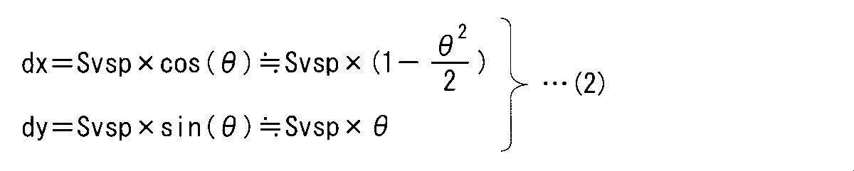
以上のことに鑑みて、走行路認識部23は、ステップS11及びS13で取得及び更新した車両挙動の積算値に基づいて垂直移動量dxを求め、垂直移動量dxを、上式(1)のLに代入することにより、中間区画線情報を求めるように構成されている。
In view of the above, the travel path recognition unit 23 obtains the vertical movement amount dx based on the integrated value of the vehicle behavior acquired and updated in Steps S11 and S13, and the vertical movement amount dx is expressed by the above equation (1). By substituting for L, intermediate lane marking information is obtained.
以上のステップS16(図4)によって、走行路認識部23は中間区画線情報を取得する。
By the above step S16 (FIG. 4), the traveling path recognition unit 23 acquires the intermediate lane marking information.
ステップS16の後、ステップS17にて、走行路認識部23は、ステップS16で得られた中間区画線情報の座標系を、検出位置DP(図5)を基準とする検出位置座標系から、現在位置CP(図5)を基準とする現在位置座標系に変換することにより、現在位置区画線情報に補正する。これにより、車両1の現在位置に対応した値を制御に使用することなどが可能となる。
After step S16, in step S17, the travel path recognition unit 23 changes the coordinate system of the intermediate lane marking information obtained in step S16 from the detected position coordinate system based on the detected position DP (FIG. 5) to the current position. By converting the current position coordinate system with reference to the position CP (FIG. 5), the current position lane line information is corrected. As a result, a value corresponding to the current position of the vehicle 1 can be used for control.
なお現在位置区画線情報は、現在位置座標系を基準とする区画線の位置及び形状に関する情報である。図5の例では、現在位置CPにおける車両1の前後方向及び左右方向をそれぞれx’方向及びy’方向とする直交座標系が、現在位置座標系として用いられている。現在位置区画線情報は、上述したように区画線の位置及び形状に関する情報であることから、区画線情報と同様に車区画線距離、車両角度、曲率及び曲率変化率を含む。
Note that the current position lane marking information is information relating to the position and shape of the lane marking based on the current position coordinate system. In the example of FIG. 5, an orthogonal coordinate system in which the front-rear direction and the left-right direction of the vehicle 1 at the current position CP are the x ′ direction and the y ′ direction, respectively, is used as the current position coordinate system. Since the current position lane line information is information related to the position and shape of the lane line as described above, the lane line distance, the vehicle angle, the curvature, and the curvature change rate are included in the same manner as the lane line information.
次に、走行路認識部23が現在位置区画線情報を求める動作について説明する。
Next, an operation in which the traveling path recognition unit 23 obtains current position lane marking information will be described.
まず、現在位置区画線情報の車区画線距離については、k0(dx)を、公知の座標変換方法で、検出位置座標系から現在位置座標系に変換すればよい。例えば、k0(dx)に対して、検出位置DPから現在位置CPまでの移動距離(dx、dy)分ずらした後、自車角度変化(θ)分だけ回転させれば、現在位置区画線情報の車区画線距離k0’が得られる。なお、k0’の検出位置座標系のx方向における車両1の位置はdxであり、現在位置座標系のx’方向における車両1の位置は0になることに注意する。以上より、現在位置区画線情報の車区画線距離k0’は、次式(3)のように表される。そこで、走行路認識部23は、中間区画線情報のk0(dx)と、車両挙動から求められるdy及びθとを次式(3)に適用して、現在位置区画線情報の車区画線距離k0’を求める。
First, for the car lane line distance of the current position lane line information, k0 (dx) may be converted from the detected position coordinate system to the current position coordinate system by a known coordinate conversion method. For example, the current position lane line information can be obtained by shifting the distance from the detection position DP to the current position CP by the moving distance (dx, dy) with respect to k0 (dx) and then rotating by the own vehicle angle change (θ). The vehicle lane line distance k0 ′ is obtained. Note that the position of the vehicle 1 in the x direction of the detection position coordinate system of k0 ′ is dx, and the position of the vehicle 1 in the x ′ direction of the current position coordinate system is 0. From the above, the car lane line distance k0 'of the current position lane line information is expressed by the following equation (3). Therefore, the traveling path recognition unit 23 applies k0 (dx) of the intermediate lane marking information and dy and θ obtained from the vehicle behavior to the following equation (3) to determine the lane marking distance of the current location lane marking information. Find k0 '.

現在位置区画線情報の車両角度は、検出位置座標系における検出時の車両傾きと区画線との傾きであるため、現在の車両傾きに変換する必要がある。検出時から現在までの車両傾きの変化量はθであることから、現在位置区画線情報の車両角度は、次式(4)のように表される。そこで、走行路認識部23は、中間区画線情報のk1(dx)と、車両挙動から求められるθとを次式(4)に適用して、現在位置区画線情報の車両角度k1’を求める。
The vehicle angle in the current position lane line information is the inclination between the vehicle inclination at the time of detection in the detection position coordinate system and the lane line, and thus needs to be converted to the current vehicle inclination. Since the change amount of the vehicle inclination from the time of detection to the present is θ, the vehicle angle of the current position lane marking information is expressed by the following equation (4). Therefore, the traveling path recognition unit 23 obtains the vehicle angle k1 ′ of the current position lane line information by applying k1 (dx) of the intermediate lane line information and θ obtained from the vehicle behavior to the following equation (4). .

現在位置区画線情報の区画線の曲率は、車両1の傾きは影響しないため、中間区画線情報の区画線の曲率をそのまま使用でき、現在位置区画線情報の曲率は、次式(5)のように表される。そこで、走行路認識部23は、中間区画線情報のk2(dx)を次式(5)に適用して、現在位置区画線情報の曲率を求める。
Since the curvature of the lane line of the current position lane line information does not affect the inclination of the vehicle 1, the curvature of the lane line of the intermediate lane line information can be used as it is, and the curvature of the current position lane line information is expressed by the following equation (5): It is expressed as follows. Therefore, the traveling path recognition unit 23 applies k2 (dx) of the intermediate lane marking information to the following equation (5) to obtain the curvature of the current position lane marking information.

以上に説明したステップS17によって、走行路認識部23は、現在位置区画線情報を取得し、当該現在位置区画線情報を推定区画線情報として用いる。
By step S17 demonstrated above, the traveling path recognition part 23 acquires present position lane line information, and uses the said present position lane line information as estimated lane line information.
ステップS14からステップS18に処理が進んだ場合、走行路認識部23は、ステップS13で記憶された区画線情報を出力して、図4の処理が終了する。ステップS17からステップS18に処理が進んだ場合、走行路認識部23は、ステップS17で取得された現在位置区画線情報を出力して、図4の処理が終了する。
When the process proceeds from step S14 to step S18, the traveling path recognition unit 23 outputs the lane marking information stored in step S13, and the process of FIG. 4 ends. When the process proceeds from step S17 to step S18, the traveling path recognition unit 23 outputs the current position lane marking information acquired in step S17, and the process of FIG. 4 ends.
ステップS15からステップS19に処理が進んだ場合、走行路認識部23は、ステップS13で記憶された区画線情報の精度は低下していると判定して、当該区画線情報を記憶から消去する。その後、図4の処理が終了する。
When the process proceeds from step S15 to step S19, the traveling path recognition unit 23 determines that the accuracy of the lane line information stored in step S13 is reduced, and deletes the lane line information from the storage. Thereafter, the process of FIG. 4 ends.
<実施の形態1のまとめ>
以上のような本実施の形態1に係る走行路認識装置によれば、走行路認識部23は、検出後走行距離と区画線検出可能距離とに基づいて、区画線情報が走行路の認識に使用可能な使用期間内の情報であるか否かを判定する。このため、走行路の認識を適切に行うことができる。 <Summary ofEmbodiment 1>
According to the traveling path recognition device according to the first embodiment as described above, the travelingpath recognition unit 23 recognizes the lane line information based on the post-detection traveling distance and the lane line detectable distance. It is determined whether the information is within a usable period of use. For this reason, a travel path can be recognized appropriately.
以上のような本実施の形態1に係る走行路認識装置によれば、走行路認識部23は、検出後走行距離と区画線検出可能距離とに基づいて、区画線情報が走行路の認識に使用可能な使用期間内の情報であるか否かを判定する。このため、走行路の認識を適切に行うことができる。 <Summary of
According to the traveling path recognition device according to the first embodiment as described above, the traveling
また本実施の形態1では、走行路認識部23は、車間距離検出部24で検出された車間距離に基づいて区画線検出可能距離を制御する。これにより、適切な区画線検出可能距離を用いることができるので、走行路の認識を適切に行うことができる。
In the first embodiment, the traveling path recognition unit 23 controls the lane line detectable distance based on the inter-vehicle distance detected by the inter-vehicle distance detection unit 24. Thereby, since an appropriate lane marking detectable distance can be used, a travel path can be recognized appropriately.
また本実施の形態1では、走行路認識部23は、現在位置区画線情報の推定に、車両挙動で補正された区画線情報を用いるため、当該推定精度を高めることができる。
Further, in the first embodiment, the travel path recognition unit 23 uses the lane line information corrected by the vehicle behavior for the estimation of the current position lane line information, so that the estimation accuracy can be increased.
<実施の形態2>
実施の形態1に係る走行路認識装置では、車間距離検出部24で検出された車間距離に基づいて区画線検出可能距離を制御するように構成した。しかしこれに限ったものではなく、以下で説明する本発明の実施の形態2に係る走行路認識装置のように、道路形状に基づいて区画線検出可能距離を制御してもよい。 <Embodiment 2>
The travel path recognition apparatus according toEmbodiment 1 is configured to control the lane line detectable distance based on the inter-vehicle distance detected by the inter-vehicle distance detection unit 24. However, the present invention is not limited to this, and the lane marking detectable distance may be controlled based on the road shape as in the travel path recognition apparatus according to Embodiment 2 of the present invention described below.
実施の形態1に係る走行路認識装置では、車間距離検出部24で検出された車間距離に基づいて区画線検出可能距離を制御するように構成した。しかしこれに限ったものではなく、以下で説明する本発明の実施の形態2に係る走行路認識装置のように、道路形状に基づいて区画線検出可能距離を制御してもよい。 <
The travel path recognition apparatus according to
なお本実施の形態2に係る走行路認識装置のブロック構成及び動作は、ステップS14(図4)を除けば、概ね、実施の形態1に係る走行路認識装置のブロック構成及び動作と同じである。そこで、以下、ステップS14について主に説明する。
The block configuration and operation of the travel path recognition apparatus according to the second embodiment are substantially the same as the block configuration and operation of the travel path recognition apparatus according to the first embodiment, except for step S14 (FIG. 4). . Therefore, step S14 will be mainly described below.
本実施の形態2に係るステップS14では、走行路認識部23は、車間距離検出部24で検出された車間距離の代わりに、ステップS13で取得した区画線情報に含まれる区画線の曲率に基づいて区画線検出可能距離を制御する。
In step S14 according to the second embodiment, the traveling path recognition unit 23 is based on the curvature of the lane line included in the lane line information acquired in step S13, instead of the inter-vehicle distance detected by the inter-vehicle distance detection unit 24. To control the lane marking detectable distance.
図6は、区画線の曲率に基づいて区画線検出可能距離を制御する動作の一例を示す図である。
FIG. 6 is a diagram illustrating an example of an operation for controlling the lane marking detectable distance based on the lane marking curvature.
なお、ここで使用されるカメラ8(図1)は、視野角の境界部分、つまり画像周縁部でひずみ等が生じるものとする。また、画像周縁部は、左右±30度(両側60度)よりも外側の部分であるものとする。この場合、本実施の形態2に係る走行路認識装置では、扇型(図6ではその扇形の右側半分を図示)の範囲内にある区画線L1を検出できることになる。
Note that the camera 8 (FIG. 1) used here is assumed to be distorted at the boundary portion of the viewing angle, that is, the peripheral portion of the image. Further, it is assumed that the peripheral edge of the image is a portion outside ± 30 degrees on the left and right (60 degrees on both sides). In this case, in the travel path recognition apparatus according to the second embodiment, it is possible to detect the lane marking L1 within the range of the fan shape (the right half of the fan shape is shown in FIG. 6).
車両1が、曲率半径Rの区画線L1の接線方向に沿って走行しているとし、区画線L1と検出範囲(右側)との交点P1が車両1から前方に距離Lp進んだ位置にあるとすれば、図6に示す3平方の定理の式から、距離Lpは下式(6)で求められる。
Suppose that the vehicle 1 is traveling along the tangential direction of the lane marking L1 having the radius of curvature R, and that the intersection P1 between the lane marking L1 and the detection range (right side) is at a position advanced from the vehicle 1 by a distance Lp. Then, the distance Lp can be obtained by the following equation (6) from the equation of the three square theorem shown in FIG.
交点P1より遠方では区画線L1を適切に検出することができないので、距離Lpは区画線検出可能距離に用いることができる。なお、曲率半径R=1/(区画線の曲率)が成り立つ。これらのことに鑑みて、走行路認識部23は、ステップS13で取得した区画線情報に含まれる区画線の曲率を、区画線検出可能距離=1/(区画線の曲率)という式に適用することにより、区画線検出可能距離を制御する。
Since the lane line L1 cannot be detected properly at the distance from the intersection P1, the distance Lp can be used as the lane line detectable distance. Note that the curvature radius R = 1 / (curvature of the lane marking) is established. In view of these points, the traveling path recognition unit 23 applies the curvature of the lane line included in the lane line information acquired in step S13 to an expression of lane line detectable distance = 1 / (curvature of the lane line). Thus, the lane marking detectable distance is controlled.
<実施の形態2のまとめ>
以上のような本実施の形態2に係る走行路認識装置によれば、走行路認識部23は、区画線の曲率に基づいて区画線検出可能距離を制御する。これにより、適切な区画線検出可能距離を用いることができるので、走行路の認識を適切に行うことができる。また、この場合には、図1におけるミリ波レーダ9、図2における車間距離検出部24、及び、図4におけるステップS14の車間距離に基づく区画線検出可能距離の制御処理は不要となる。 <Summary ofEmbodiment 2>
According to the traveling path recognition device according to the second embodiment as described above, the travelingpath recognition unit 23 controls the lane marking detectable distance based on the curvature of the lane marking. Thereby, since an appropriate lane marking detectable distance can be used, a travel path can be recognized appropriately. Further, in this case, the millimeter wave radar 9 in FIG. 1, the inter-vehicle distance detection unit 24 in FIG. 2, and the lane marking detectable distance control process based on the inter-vehicle distance in step S14 in FIG.
以上のような本実施の形態2に係る走行路認識装置によれば、走行路認識部23は、区画線の曲率に基づいて区画線検出可能距離を制御する。これにより、適切な区画線検出可能距離を用いることができるので、走行路の認識を適切に行うことができる。また、この場合には、図1におけるミリ波レーダ9、図2における車間距離検出部24、及び、図4におけるステップS14の車間距離に基づく区画線検出可能距離の制御処理は不要となる。 <Summary of
According to the traveling path recognition device according to the second embodiment as described above, the traveling
ただし必要であれば、走行路認識部23は、車間距離検出部24で検出された車間距離と、区画線情報に含まれる区画線の曲率とに基づいて区画線検出可能距離を制御してもよい。例えば、走行路認識部23は、車間距離に基づいて得られる距離と、区画線の曲率に基づいて得られる距離とのうち短い方の距離を区画線検出可能距離として用いてもよい。
However, if necessary, the travel path recognition unit 23 may control the lane line detectable distance based on the inter-vehicle distance detected by the inter-vehicle distance detection unit 24 and the curvature of the lane line included in the lane line information. Good. For example, the travel path recognizing unit 23 may use a shorter distance of the distance obtained based on the inter-vehicle distance and the distance obtained based on the curvature of the lane marking as the lane marking detectable distance.
<実施の形態3>
実施の形態2に係る走行路認識装置では、区画線の曲率に基づいて区画線検出可能距離を制御するように構成した。しかしこれに限ったものではなく、以下で説明する本発明の実施の形態3に係る走行路認識装置のように、区画線の曲率に加えて、区画線情報に含まれる車両角度も考慮して区画線検出可能距離を制御してもよい。 <Embodiment 3>
The travel path recognition apparatus according toEmbodiment 2 is configured to control the lane line detectable distance based on the curvature of the lane line. However, the present invention is not limited to this, and the vehicle angle included in the lane marking information is also taken into consideration in addition to the curvature of the lane marking as in the travel path recognition device according to the third embodiment of the present invention described below. The lane marking detectable distance may be controlled.
実施の形態2に係る走行路認識装置では、区画線の曲率に基づいて区画線検出可能距離を制御するように構成した。しかしこれに限ったものではなく、以下で説明する本発明の実施の形態3に係る走行路認識装置のように、区画線の曲率に加えて、区画線情報に含まれる車両角度も考慮して区画線検出可能距離を制御してもよい。 <
The travel path recognition apparatus according to
例えば、一般的に、渋滞時などの先行車両追従制御時には、高速道におけるレーンキープアシスト機能使用時よりも、車速が低く、曲率が大きく(カーブがきつく)、区画線に対する車両角度も大きくなる傾向にある。そこで本実施の形態3では、走行路認識部23は、区画線及び車両挙動も考慮して区画線を検出できる範囲を推定し、区画線検出可能距離を制御する。
For example, in general, when following vehicle follow-up control such as in a traffic jam, the vehicle speed is lower, the curvature is larger (the curve is tighter), and the vehicle angle with respect to the lane marking is larger than when using the lane keep assist function on a highway. It is in. Therefore, in the third embodiment, the traveling path recognition unit 23 estimates the range in which the lane line can be detected in consideration of the lane line and the vehicle behavior, and controls the lane line detectable distance.
なお本実施の形態3に係る走行路認識装置のブロック構成及び動作は、ステップS14(図4)を除けば、概ね、実施の形態1に係る走行路認識装置のブロック構成及び動作と同じである。そこで、以下、ステップS14について主に説明する。
The block configuration and operation of the travel path recognition apparatus according to the third embodiment are substantially the same as the block configuration and operation of the travel path recognition apparatus according to the first embodiment, except for step S14 (FIG. 4). . Therefore, step S14 will be mainly described below.
本実施の形態3に係るステップS14では、走行路認識部23は、車間距離検出部24で検出された車間距離の代わりに、ステップS13で取得した区画線情報に含まれる区画線の曲率及び車両角度に基づいて区画線検出可能距離を制御する。
In step S14 according to the third embodiment, the travel path recognition unit 23 replaces the inter-vehicle distance detected by the inter-vehicle distance detection unit 24 with the lane line curvature and vehicle included in the lane line information acquired in step S13. The lane marking detectable distance is controlled based on the angle.
図7は、区画線の曲率及び車両角度に基づいて区画線検出可能距離を制御する動作の一例を示す図である。
FIG. 7 is a diagram illustrating an example of an operation for controlling the lane marking detectable distance based on the lane marking curvature and the vehicle angle.
図7には、図6の状態において、車両角度が、区画線L1と検出範囲が離れる方向にθ度傾いていた状態が示されている。このとき車両1の区画線L1の半径方向と、車両1から交点P1への方向とが成す角度は、視野角が30度である場合、(60+θ)度となる。
FIG. 7 shows a state in which the vehicle angle is inclined by θ degrees in the direction away from the lane marking L1 and the detection range in the state of FIG. At this time, the angle formed by the radial direction of the lane marking L1 of the vehicle 1 and the direction from the vehicle 1 to the intersection P1 is (60 + θ) degrees when the viewing angle is 30 degrees.
本実施の形態3においても、実施の形態2と同様に、車両1が、曲率半径Rの区画線L1の接線方向に沿って走行しているとし、区画線L1と検出範囲(右側)との交点P1が車両1から前方に距離Lp進んだ位置にあるとすれば、図7に示す3平方の定理の式から、距離Lpは下式(7)で求められる。
Also in the third embodiment, as in the second embodiment, it is assumed that the vehicle 1 is traveling along the tangential direction of the lane marking L1 having the curvature radius R, and the lane marking L1 and the detection range (right side) Assuming that the intersection point P1 is at a position advanced from the vehicle 1 by the distance Lp, the distance Lp is obtained by the following equation (7) from the equation of the three-square theorem shown in FIG.
実施の形態2と同様にして、走行路認識部23は、ステップS13で取得した区画線情報に含まれる区画線の曲率及び車両角度を、区画線検出可能距離=2×cos(60+車両角度)/(区画線の曲率)という式に適用することにより、区画線検出可能距離を制御する。
In the same manner as in the second embodiment, the traveling path recognition unit 23 sets the lane line curvature and the vehicle angle included in the lane line information acquired in step S13, as the lane line detectable distance = 2 × cos (60 + vehicle angle). By applying this to the expression / (curvature of lane markings), the lane marking detectable distance is controlled.
<実施の形態3のまとめ>
以上のような本実施の形態3に係る走行路認識装置によれば、走行路認識部23は、区画線の曲率及び車両角度に基づいて区画線検出可能距離を制御する。これにより、適切な区画線検出可能距離を用いることができるので、走行路の認識を適切に行うことができる。また、この場合には、図1におけるミリ波レーダ9、図2における車間距離検出部24、及び、図4におけるステップS14の車間距離に基づく区画線検出可能距離の制御処理は不要となる。 <Summary ofEmbodiment 3>
According to the traveling path recognition device according to the third embodiment as described above, the travelingpath recognition unit 23 controls the lane line detectable distance based on the curvature of the lane marking and the vehicle angle. Thereby, since an appropriate lane marking detectable distance can be used, a travel path can be recognized appropriately. Further, in this case, the millimeter wave radar 9 in FIG. 1, the inter-vehicle distance detection unit 24 in FIG. 2, and the lane marking detectable distance control process based on the inter-vehicle distance in step S14 in FIG.
以上のような本実施の形態3に係る走行路認識装置によれば、走行路認識部23は、区画線の曲率及び車両角度に基づいて区画線検出可能距離を制御する。これにより、適切な区画線検出可能距離を用いることができるので、走行路の認識を適切に行うことができる。また、この場合には、図1におけるミリ波レーダ9、図2における車間距離検出部24、及び、図4におけるステップS14の車間距離に基づく区画線検出可能距離の制御処理は不要となる。 <Summary of
According to the traveling path recognition device according to the third embodiment as described above, the traveling
ただし必要であれば、走行路認識部23は、車間距離検出部24で検出された車間距離と、区画線情報に含まれる区画線の曲率とに基づいて区画線検出可能距離を制御してもよい。例えば、走行路認識部23は、車間距離に基づいて得られる距離と、区画線の曲率及び車両角度に基づいて得られる距離とのうち短い方の距離を区画線検出可能距離として用いてもよい。
However, if necessary, the travel path recognition unit 23 may control the lane line detectable distance based on the inter-vehicle distance detected by the inter-vehicle distance detection unit 24 and the curvature of the lane line included in the lane line information. Good. For example, the travel path recognizing unit 23 may use the shorter distance among the distance obtained based on the inter-vehicle distance and the distance obtained based on the curvature of the lane marking and the vehicle angle as the lane marking detectable distance. .
<変形例>
以上の説明では、走行路の認識結果をレーンキープアシストに使用する装置について述べたが、これに限らず、走行路の認識結果を車線逸脱警報装置、自動運転装置等に使用してもよい。実施の形態で説明した技術は、それぞれの装置で区画線情報、ひいては走行路を使用する際に適用することができる。 <Modification>
In the above description, the device that uses the recognition result of the traveling road for the lane keep assist has been described. The technology described in the embodiment can be applied when using the lane marking information and, consequently, the travel path in each device.
<その他の変形例>
走行路認識装置における区画線取得部、車両挙動取得部及び走行路認識部を、以下「区画線取得部等」と記す。区画線取得部等は、図1のコントロールユニット10に対応する図8の処理回路81により実現される。すなわち、処理回路81は、区画線情報を取得する区画線取得部と、区画線情報の取得時から現在までの、車両1の車速に関する車両挙動を取得する車両挙動取得部と、区画線情報に基づいて車両1が走行する走行路を認識する走行路認識部と、を備える。処理回路81には、専用のハードウェアが適用されてもよいし、メモリに格納されるプログラムを実行するプロセッサが適用されてもよい。プロセッサには、例えば、中央処理装置、処理装置、演算装置、マイクロプロセッサ、マイクロコンピュータ、DSP(Digital Signal Processor)などが該当する。 <Other variations>
Hereinafter, the lane line acquisition unit, the vehicle behavior acquisition unit, and the travel path recognition unit in the travel path recognition device are referred to as “a lane line acquisition unit and the like”. The lane marking acquisition unit and the like are realized by theprocessing circuit 81 in FIG. 8 corresponding to the control unit 10 in FIG. That is, the processing circuit 81 includes a lane line acquisition unit that acquires lane line information, a vehicle behavior acquisition unit that acquires vehicle behavior related to the vehicle speed of the vehicle 1 from the time of acquisition of the lane line information to the present time, and lane line information. A travel path recognition unit that recognizes a travel path on which the vehicle 1 travels. Dedicated hardware may be applied to the processing circuit 81, or a processor that executes a program stored in the memory may be applied. The processor corresponds to, for example, a central processing unit, a processing unit, an arithmetic unit, a microprocessor, a microcomputer, a DSP (Digital Signal Processor) and the like.
走行路認識装置における区画線取得部、車両挙動取得部及び走行路認識部を、以下「区画線取得部等」と記す。区画線取得部等は、図1のコントロールユニット10に対応する図8の処理回路81により実現される。すなわち、処理回路81は、区画線情報を取得する区画線取得部と、区画線情報の取得時から現在までの、車両1の車速に関する車両挙動を取得する車両挙動取得部と、区画線情報に基づいて車両1が走行する走行路を認識する走行路認識部と、を備える。処理回路81には、専用のハードウェアが適用されてもよいし、メモリに格納されるプログラムを実行するプロセッサが適用されてもよい。プロセッサには、例えば、中央処理装置、処理装置、演算装置、マイクロプロセッサ、マイクロコンピュータ、DSP(Digital Signal Processor)などが該当する。 <Other variations>
Hereinafter, the lane line acquisition unit, the vehicle behavior acquisition unit, and the travel path recognition unit in the travel path recognition device are referred to as “a lane line acquisition unit and the like”. The lane marking acquisition unit and the like are realized by the
処理回路81が専用のハードウェアである場合、処理回路81は、例えば、単一回路、複合回路、プログラム化したプロセッサ、並列プログラム化したプロセッサ、ASIC(Application Specific Integrated Circuit)、FPGA(Field Programmable Gate Array)、またはこれらを組み合わせたものが該当する。区画線取得部等の各部の機能それぞれは、処理回路を分散させた回路で実現されてもよいし、各部の機能をまとめて一つの処理回路で実現されてもよい。
When the processing circuit 81 is dedicated hardware, the processing circuit 81 includes, for example, a single circuit, a composite circuit, a programmed processor, a parallel programmed processor, an ASIC (Application Specific Integrated Circuit), an FPGA (Field Programmable Gate). Array) or a combination thereof. Each function of each unit such as a lane marking acquisition unit may be realized by a circuit in which processing circuits are distributed, or the function of each unit may be realized by a single processing circuit.
処理回路81がプロセッサである場合、区画線取得部等の機能は、ソフトウェア等との組み合わせにより実現される。なお、ソフトウェア等には、例えば、ソフトウェア、ファームウェア、または、ソフトウェア及びファームウェアが該当する。ソフトウェア等はプログラムとして記述され、メモリに格納される。図9に示すように、処理回路81に適用されるプロセッサ83は、メモリ84に記憶されたプログラムを読み出して実行することにより、入出力制御インタフェース(I/F)82を介して図1の車輪速センサ6、ヨーレートセンサ7、カメラ8及びモータ3等の外部装置との間で入出力される信号を処理する各部の機能を実現する。すなわち、走行路認識装置は、処理回路81により実行されるときに、区画線情報を取得するステップと、区画線情報の取得時から現在までの、車両1の車速に関する車両挙動を取得するステップと、区画線情報に基づいて車両1が走行する走行路を認識するステップと、が結果的に実行されることになるプログラムを格納するためのメモリ84を備える。換言すれば、このプログラムは、区画線取得部等の手順や方法をコンピュータに実行させるものであるともいえる。ここで、メモリ84は、例えば、RAM(Random Access Memory)、ROM(Read Only Memory)、フラッシュメモリー、EPROM(Erasable Programmable Read Only Memory)、EEPROM(Electrically Erasable Programmable Read Only Memory)などの、不揮発性または揮発性の半導体メモリ、HDD(Hard Disk Drive)、磁気ディスク、フレキシブルディスク、光ディスク、コンパクトディスク、ミニディスク、DVD(Digital Versatile Disc)、そのドライブ装置等、または、今後使用されるあらゆる記憶媒体であってもよい。
When the processing circuit 81 is a processor, the functions of the lane marking acquisition unit and the like are realized by a combination with software or the like. Note that the software or the like corresponds to, for example, software, firmware, or software and firmware. Software or the like is described as a program and stored in a memory. As shown in FIG. 9, the processor 83 applied to the processing circuit 81 reads and executes the program stored in the memory 84, whereby the wheel of FIG. 1 is connected via the input / output control interface (I / F) 82. The function of each part which processes the signal input / output between external devices, such as the speed sensor 6, the yaw rate sensor 7, the camera 8, and the motor 3, is implement | achieved. That is, the travel path recognition device, when executed by the processing circuit 81, acquires the lane line information, and acquires the vehicle behavior related to the vehicle speed of the vehicle 1 from the time of acquisition of the lane line information to the present time. And a step of recognizing the travel route on which the vehicle 1 travels based on the lane marking information, and a memory 84 for storing a program to be executed as a result. In other words, it can be said that this program causes a computer to execute procedures and methods such as a lane marking acquisition unit. Here, the memory 84 is nonvolatile or non-volatile such as RAM (Random Access Memory), ROM (Read Only Memory), flash memory, EPROM (Erasable Programmable Read Only Memory), EEPROM (Electrically Erasable Programmable Read Only Memory), or the like. Volatile semiconductor memory, HDD (Hard Disk Drive), magnetic disk, flexible disk, optical disk, compact disk, mini disk, DVD (Digital Versatile Disk), its drive device, etc., or any storage media used in the future May be.
以上、区画線取得部等の各機能が、ハードウェア及びソフトウェア等のいずれか一方で実現される構成について説明した。しかしこれに限ったものではなく、区画線取得部等の一部を専用のハードウェアで実現し、別の一部をソフトウェア等で実現する構成であってもよい。例えば、区画線取得部及び車両挙動取得部についてはレシーバなどの専用のハードウェアとしての処理回路でその機能を実現し、それ以外についてはプロセッサ83としての処理回路81がメモリ84に格納されたプログラムを読み出して実行することによってその機能を実現することが可能である。
As described above, the configuration in which each function such as the lane marking acquisition unit is realized by either hardware or software has been described. However, the present invention is not limited to this, and a configuration may be adopted in which a part of the lane marking acquisition unit or the like is realized by dedicated hardware and another part is realized by software or the like. For example, for the lane marking acquisition unit and the vehicle behavior acquisition unit, the function is realized by a processing circuit as dedicated hardware such as a receiver, and the processing circuit 81 as the processor 83 is stored in the memory 84 otherwise. The function can be realized by reading out and executing.
以上のように、処理回路81は、ハードウェア、ソフトウェア等、またはこれらの組み合わせによって、上述の各機能を実現することができる。
As described above, the processing circuit 81 can realize the above functions by hardware, software, or the like, or a combination thereof.
また、以上で説明した走行路認識装置は、PND(Portable Navigation Device)などのナビゲーション装置と、携帯電話、スマートフォン及びタブレットなどの携帯端末を含む通信端末と、これらにインストールされるアプリケーションの機能と、サーバとを適宜に組み合わせてシステムとして構築される走行路認識システムにも適用することができる。この場合、以上で説明した走行路認識装置の各機能あるいは各構成要素は、前記システムを構築する各機器に分散して配置されてもよいし、いずれかの機器に集中して配置されてもよい。
In addition, the travel path recognition device described above includes navigation devices such as PND (Portable Navigation) Device, communication terminals including mobile terminals such as mobile phones, smartphones, and tablets, and application functions installed on these devices, The present invention can also be applied to a traveling path recognition system constructed as a system by appropriately combining servers. In this case, each function or each component of the traveling path recognition device described above may be distributed and arranged in each device that constructs the system, or may be concentrated on any device. Good.
なお、本発明は、その発明の範囲内において、各実施の形態及び各変形例を自由に組み合わせたり、各実施の形態及び各変形例を適宜、変形、省略したりすることが可能である。
The present invention can be freely combined with each embodiment and each modification within the scope of the invention, or can be appropriately modified and omitted with each embodiment and each modification.
本発明は詳細に説明されたが、上記した説明は、すべての態様において、例示であって、本発明がそれに限定されるものではない。例示されていない無数の変形例が、本発明の範囲から外れることなく想定され得るものと解される。
Although the present invention has been described in detail, the above description is illustrative in all aspects, and the present invention is not limited thereto. It is understood that countless variations that are not illustrated can be envisaged without departing from the scope of the present invention.
1 車両、21 車両挙動検出部、22 区画線検出部、23 走行路認識部、24 車間距離検出部。
1 vehicle, 21 vehicle behavior detection unit, 22 lane marking detection unit, 23 travel path recognition unit, 24 inter-vehicle distance detection unit.
Claims (6)
- 車両の位置を基準とする、前記車両前方の区画線の位置及び形状に関する区画線情報を取得する区画線取得部と、
前記区画線情報の取得時から現在までの、前記車両の車速に関する車両挙動を取得する車両挙動取得部と、
前記区画線情報に基づいて前記車両が走行する走行路を認識する走行路認識部と
を備え、
前記走行路認識部は、
前記車両挙動の前記車速に基づいて、前記区画線情報の取得時から現在まで前記車両が走行した走行距離を求め、前記車両の前記位置から前方への距離であって前記区画線情報の前記区画線を取得可能な距離として予め定められた区画線取得可能距離と、前記走行距離とに基づいて、前記区画線情報が前記走行路の認識に使用可能な使用期間内の情報であるか否かを判定する、走行路認識装置。 A lane line acquisition unit that acquires lane line information related to the position and shape of the lane line ahead of the vehicle, based on the position of the vehicle;
A vehicle behavior acquisition unit that acquires a vehicle behavior related to a vehicle speed of the vehicle from the time of acquisition of the lane marking information to the present time;
A travel path recognition unit that recognizes a travel path on which the vehicle travels based on the lane marking information;
The travel path recognition unit
Based on the vehicle speed of the vehicle behavior, the travel distance traveled by the vehicle from the time of acquisition of the lane line information to the present is obtained, and the distance from the position of the vehicle to the front is the lane line information. Whether or not the lane line information is information within a usable period that can be used for recognizing the travel path, based on a lane line acquisition distance that is predetermined as a distance from which a line can be acquired and the travel distance A travel path recognition device for determining - 請求項1に記載の走行路認識装置であって、
前記車両前方の別の車両である先行車両と、前記車両との間の車間距離を取得する車間距離取得部をさらに備え、
前記走行路認識部は、
前記車間距離に基づいて前記区画線取得可能距離を制御する、走行路認識装置。 The travel path recognition device according to claim 1,
An inter-vehicle distance acquisition unit that acquires an inter-vehicle distance between a preceding vehicle that is another vehicle ahead of the vehicle and the vehicle;
The travel path recognition unit
A travel path recognition device that controls the lane marking obtainable distance based on the inter-vehicle distance. - 請求項1または請求項2に記載の走行路認識装置であって、
前記区画線情報は、前記区画線の曲率を含み、
前記走行路認識部は、
前記曲率に基づいて前記区画線取得可能距離を制御する、走行路認識装置。 The travel path recognition device according to claim 1 or 2,
The lane marking information includes a curvature of the lane marking,
The travel path recognition unit
A travel path recognition device that controls the lane marking obtainable distance based on the curvature. - 請求項1または請求項2に記載の走行路認識装置であって、
前記区画線情報は、
前記区画線の曲率と、前記区画線の前記車両側方の部分に対する前記車両の進行方向の傾きである車両角度とを含み、
前記走行路認識部は、
前記曲率及び前記車両角度に基づいて前記区画線取得可能距離を制御する、走行路認識装置。 The travel path recognition device according to claim 1 or 2,
The lane marking information is
Including a curvature of the lane marking and a vehicle angle that is an inclination of a traveling direction of the vehicle with respect to the vehicle lateral portion of the lane marking;
The travel path recognition unit
A travel path recognition apparatus that controls the lane marking obtainable distance based on the curvature and the vehicle angle. - 請求項1から請求項4のうちのいずれか1項に記載の走行路認識装置であって、
前記車両挙動は、
前記区画線情報の取得時から現在までの、前記車両のヨーレートに関する挙動も含み、
前記走行路認識部は、
前記車両挙動に基づいて、前記使用期間内の前記区画線情報を、前記車両の現在位置を基準とする、前記区画線の位置及び形状に関する現在位置区画線情報に補正し、前記現在位置区画線情報を前記走行路の認識に使用する、走行路認識装置。 The travel path recognition device according to any one of claims 1 to 4,
The vehicle behavior is
Including the behavior related to the yaw rate of the vehicle from the time of acquisition of the lane marking information to the present,
The travel path recognition unit
Based on the vehicle behavior, the lane line information within the period of use is corrected to current position lane line information related to the position and shape of the lane line based on the current position of the vehicle, and the current position lane line A travel path recognition apparatus that uses information for recognizing the travel path. - 車両の位置を基準とする、前記車両前方の区画線の位置及び形状に関する区画線情報を取得し、
前記区画線情報の取得時から現在までの、前記車両の車速に関する車両挙動を取得し、
前記区画線情報に基づいて前記車両が走行する走行路を認識し、
前記走行路の認識は、
前記車両挙動の前記車速に基づいて、前記区画線情報の取得時から現在まで前記車両が走行した走行距離を求め、前記車両の前記位置から前方への距離であって前記区画線情報の前記区画線を取得可能な距離として予め定められた区画線取得可能距離と、前記走行距離とに基づいて、前記区画線情報が前記走行路の認識に使用可能な使用期間内の情報であるか否かを判定することを含む、走行路認識方法。 The lane line information related to the position and shape of the lane line ahead of the vehicle is obtained with reference to the position of the vehicle,
Acquire vehicle behavior related to the vehicle speed from the time of acquisition of the lane marking information to the present,
Recognizing a travel route on which the vehicle travels based on the lane marking information;
The recognition of the travel path is
Based on the vehicle speed of the vehicle behavior, the travel distance traveled by the vehicle from the time of acquisition of the lane line information to the present is obtained, and the distance from the position of the vehicle to the front is the lane line information. Whether or not the lane line information is information within a usable period that can be used for recognizing the travel path, based on a lane line acquisition distance that is predetermined as a distance from which a line can be acquired and the travel distance A travel path recognition method comprising determining
Priority Applications (5)
| Application Number | Priority Date | Filing Date | Title |
|---|---|---|---|
| EP17891437.0A EP3569462B1 (en) | 2017-01-10 | 2017-01-10 | Travel path recognition device and travel path recognition method |
| PCT/JP2017/000405 WO2018131062A1 (en) | 2017-01-10 | 2017-01-10 | Travel path recognition device and travel path recognition method |
| US16/474,333 US11560145B2 (en) | 2017-01-10 | 2017-01-10 | Travel path recognition apparatus and travel path recognition method |
| CN201780082347.7A CN110167813B (en) | 2017-01-10 | 2017-01-10 | Travel route recognition device and travel route recognition method |
| JP2017538740A JP6261832B1 (en) | 2017-01-10 | 2017-01-10 | Traveling path recognition device and traveling path recognition method |
Applications Claiming Priority (1)
| Application Number | Priority Date | Filing Date | Title |
|---|---|---|---|
| PCT/JP2017/000405 WO2018131062A1 (en) | 2017-01-10 | 2017-01-10 | Travel path recognition device and travel path recognition method |
Publications (1)
| Publication Number | Publication Date |
|---|---|
| WO2018131062A1 true WO2018131062A1 (en) | 2018-07-19 |
Family
ID=60989173
Family Applications (1)
| Application Number | Title | Priority Date | Filing Date |
|---|---|---|---|
| PCT/JP2017/000405 WO2018131062A1 (en) | 2017-01-10 | 2017-01-10 | Travel path recognition device and travel path recognition method |
Country Status (5)
| Country | Link |
|---|---|
| US (1) | US11560145B2 (en) |
| EP (1) | EP3569462B1 (en) |
| JP (1) | JP6261832B1 (en) |
| CN (1) | CN110167813B (en) |
| WO (1) | WO2018131062A1 (en) |
Cited By (1)
| Publication number | Priority date | Publication date | Assignee | Title |
|---|---|---|---|---|
| DE112021006879T5 (en) | 2021-01-22 | 2023-11-30 | Mitsubishi Electric Corporation | Target trajectory calculation device, vehicle control device and target trajectory calculation method |
Families Citing this family (7)
| Publication number | Priority date | Publication date | Assignee | Title |
|---|---|---|---|---|
| KR102553247B1 (en) * | 2018-04-27 | 2023-07-07 | 주식회사 에이치엘클레무브 | Lane keep assist system and method for improving safety in forward vehicle follower longitudinal control |
| WO2020008221A1 (en) * | 2018-07-04 | 2020-01-09 | 日産自動車株式会社 | Travel assistance method and travel assistance device |
| JP7229710B2 (en) * | 2018-09-26 | 2023-02-28 | 本田技研工業株式会社 | VEHICLE CONTROL DEVICE, VEHICLE CONTROL METHOD, AND PROGRAM |
| JP7399255B2 (en) * | 2020-02-14 | 2023-12-15 | 三菱電機株式会社 | Vehicle travel route generation device and vehicle travel route generation method |
| DE112020007074T5 (en) * | 2020-04-13 | 2023-03-02 | Mitsubishi Electric Corporation | LANE DETECTION DEVICE AND LANE DETECTION METHOD |
| US11436843B2 (en) | 2021-01-21 | 2022-09-06 | Qualcomm Incorporated | Lane mapping and localization using periodically-updated anchor frames |
| DE102022114449A1 (en) * | 2022-06-08 | 2023-12-14 | Bayerische Motoren Werke Aktiengesellschaft | METHOD AND DEVICE FOR SETTING AN OPERATING STATE OF A DRIVING ASSISTANCE SYSTEM |
Citations (4)
| Publication number | Priority date | Publication date | Assignee | Title |
|---|---|---|---|---|
| JPH09311999A (en) * | 1996-05-23 | 1997-12-02 | Nissan Diesel Motor Co Ltd | Recognition device for white line of road |
| JP2005038225A (en) * | 2003-07-16 | 2005-02-10 | Nissan Motor Co Ltd | Lane follow-up device |
| JP2012058984A (en) | 2010-09-08 | 2012-03-22 | Fuji Heavy Ind Ltd | Lane estimating device |
| JP2014051241A (en) * | 2012-09-10 | 2014-03-20 | Toyota Motor Corp | Vehicle control device |
Family Cites Families (15)
| Publication number | Priority date | Publication date | Assignee | Title |
|---|---|---|---|---|
| US3657821A (en) * | 1969-12-31 | 1972-04-25 | Peter A De Nure | Vehicle orienting device and method |
| DE4332836C1 (en) * | 1993-09-27 | 1994-09-15 | Daimler Benz Ag | Device for steering a vehicle with controlled tracking |
| EP1504276B1 (en) * | 2002-05-03 | 2012-08-08 | Donnelly Corporation | Object detection system for vehicle |
| DE102005025387A1 (en) * | 2004-09-30 | 2006-05-04 | Daimlerchrysler Ag | Method and device for driver's warning or to actively intervene in the driving dynamics, if threatening to leave the lane |
| JP4950858B2 (en) * | 2007-11-29 | 2012-06-13 | アイシン・エィ・ダブリュ株式会社 | Image recognition apparatus and image recognition program |
| TW201043507A (en) * | 2009-06-05 | 2010-12-16 | Automotive Res & Testing Ct | Method for detection of tilting of automobile and headlamp automatic horizontal system using such a method |
| DE102010053964A1 (en) | 2010-12-09 | 2011-08-25 | Daimler AG, 70327 | Driver assistance system e.g. lane keeping support system, for supporting driver during transverse steering of car in e.g. location, has control unit that controls start and end times and/or strength of support action based on information |
| US20130274959A1 (en) * | 2010-12-15 | 2013-10-17 | Toyota Jidosha Kabushiki Kaisha | Driving support apparatus, driving support method, and vehicle |
| KR101502510B1 (en) * | 2013-11-26 | 2015-03-13 | 현대모비스 주식회사 | Apparatus and method for controlling lane keeping of vehicle |
| JP6260233B2 (en) | 2013-12-02 | 2018-01-17 | 富士通株式会社 | Information processing apparatus, camera mounting angle estimation method, and program |
| JP6272204B2 (en) | 2014-10-02 | 2018-01-31 | 株式会社Soken | Road lane marking information acquisition device |
| US9555802B2 (en) * | 2015-03-25 | 2017-01-31 | Honda Motor Co., Ltd. | Driving support device |
| JP6469220B2 (en) * | 2015-06-15 | 2019-02-13 | 三菱電機株式会社 | Traveling lane discrimination device and traveling lane discrimination method |
| CN105539293B (en) * | 2016-02-03 | 2018-01-09 | 北京中科慧眼科技有限公司 | Lane departure warning method and device and car steering accessory system |
| JP6714714B2 (en) * | 2016-10-18 | 2020-06-24 | 本田技研工業株式会社 | Vehicle control device |
-
2017
- 2017-01-10 US US16/474,333 patent/US11560145B2/en active Active
- 2017-01-10 JP JP2017538740A patent/JP6261832B1/en active Active
- 2017-01-10 CN CN201780082347.7A patent/CN110167813B/en active Active
- 2017-01-10 EP EP17891437.0A patent/EP3569462B1/en active Active
- 2017-01-10 WO PCT/JP2017/000405 patent/WO2018131062A1/en unknown
Patent Citations (4)
| Publication number | Priority date | Publication date | Assignee | Title |
|---|---|---|---|---|
| JPH09311999A (en) * | 1996-05-23 | 1997-12-02 | Nissan Diesel Motor Co Ltd | Recognition device for white line of road |
| JP2005038225A (en) * | 2003-07-16 | 2005-02-10 | Nissan Motor Co Ltd | Lane follow-up device |
| JP2012058984A (en) | 2010-09-08 | 2012-03-22 | Fuji Heavy Ind Ltd | Lane estimating device |
| JP2014051241A (en) * | 2012-09-10 | 2014-03-20 | Toyota Motor Corp | Vehicle control device |
Non-Patent Citations (1)
| Title |
|---|
| See also references of EP3569462A4 |
Cited By (1)
| Publication number | Priority date | Publication date | Assignee | Title |
|---|---|---|---|---|
| DE112021006879T5 (en) | 2021-01-22 | 2023-11-30 | Mitsubishi Electric Corporation | Target trajectory calculation device, vehicle control device and target trajectory calculation method |
Also Published As
| Publication number | Publication date |
|---|---|
| US20190351901A1 (en) | 2019-11-21 |
| JPWO2018131062A1 (en) | 2019-01-17 |
| US11560145B2 (en) | 2023-01-24 |
| JP6261832B1 (en) | 2018-01-17 |
| EP3569462A4 (en) | 2020-04-15 |
| CN110167813A (en) | 2019-08-23 |
| EP3569462A1 (en) | 2019-11-20 |
| CN110167813B (en) | 2022-05-03 |
| EP3569462B1 (en) | 2022-06-01 |
Similar Documents
| Publication | Publication Date | Title |
|---|---|---|
| JP6261832B1 (en) | Traveling path recognition device and traveling path recognition method | |
| US10019017B2 (en) | Autonomous driving system | |
| JP6242573B2 (en) | Roadway recognition method and system | |
| JP6407447B1 (en) | Traveling path recognition device and traveling path recognition method | |
| CN111066071B (en) | Position error correction method and position error correction device for driving assistance vehicle | |
| US10821975B2 (en) | Lane division line recognition apparatus, lane division line recognition method, driving assist apparatus including lane division line recognition apparatus, and driving assist method including lane division line recognition method | |
| US9120486B1 (en) | Vehicle lane keeping techniques | |
| JP4832489B2 (en) | Lane judgment device | |
| JP7013727B2 (en) | Vehicle control device | |
| JPWO2018211582A1 (en) | Operation prediction method and operation prediction device for driving assistance device | |
| US20170025013A1 (en) | Distance calculation apparatus, distance calculation method, driving assist apparatus, and driving assist system | |
| US20230150499A1 (en) | Vehicle control system and vehicle driving method using the vehicle control system | |
| JP2008185554A (en) | Route guidance device for vehicle | |
| US11334073B2 (en) | Autonomous driving device | |
| JP7122211B2 (en) | PARKING ASSIST DEVICE AND PARKING ASSIST METHOD | |
| JP2009210499A (en) | Tire diameter information correcting apparatus | |
| JP2019160156A (en) | Vehicle control apparatus and vehicle control method | |
| US20220379878A1 (en) | Parking Assist System and Parking Assist Method | |
| JP2019156198A (en) | Vehicle position determination device | |
| JP2018043539A (en) | Lane deviation suppression apparatus | |
| JP7236279B2 (en) | Driving support method and driving support device | |
| US20230159021A1 (en) | Parking Assistance Device | |
| JP7169892B2 (en) | Driving support method and driving support device | |
| JP2022181771A (en) | Vehicle detection device, vehicle detection method, and vehicle detection program | |
| JP6667718B2 (en) | Entry avoidance control device and approach avoidance control method |
Legal Events
| Date | Code | Title | Description |
|---|---|---|---|
| ENP | Entry into the national phase |
Ref document number: 2017538740 Country of ref document: JP Kind code of ref document: A |
|
| 121 | Ep: the epo has been informed by wipo that ep was designated in this application |
Ref document number: 17891437 Country of ref document: EP Kind code of ref document: A1 |
|
| NENP | Non-entry into the national phase |
Ref country code: DE |
|
| ENP | Entry into the national phase |
Ref document number: 2017891437 Country of ref document: EP Effective date: 20190812 |