JP6242573B2 - Roadway recognition method and system - Google Patents
Roadway recognition method and system Download PDFInfo
- Publication number
- JP6242573B2 JP6242573B2 JP2012270596A JP2012270596A JP6242573B2 JP 6242573 B2 JP6242573 B2 JP 6242573B2 JP 2012270596 A JP2012270596 A JP 2012270596A JP 2012270596 A JP2012270596 A JP 2012270596A JP 6242573 B2 JP6242573 B2 JP 6242573B2
- Authority
- JP
- Japan
- Prior art keywords
- road
- lane
- width
- vehicle
- calculating
- Prior art date
- Legal status (The legal status is an assumption and is not a legal conclusion. Google has not performed a legal analysis and makes no representation as to the accuracy of the status listed.)
- Active
Links
- 238000000034 method Methods 0.000 title claims description 34
- 230000000694 effects Effects 0.000 claims description 3
- 238000000926 separation method Methods 0.000 description 6
- 230000002159 abnormal effect Effects 0.000 description 2
- 238000010586 diagram Methods 0.000 description 2
- 206010039203 Road traffic accident Diseases 0.000 description 1
- 238000007796 conventional method Methods 0.000 description 1
- 238000012986 modification Methods 0.000 description 1
- 230000004048 modification Effects 0.000 description 1
Images
Classifications
-
- B—PERFORMING OPERATIONS; TRANSPORTING
- B60—VEHICLES IN GENERAL
- B60W—CONJOINT CONTROL OF VEHICLE SUB-UNITS OF DIFFERENT TYPE OR DIFFERENT FUNCTION; CONTROL SYSTEMS SPECIALLY ADAPTED FOR HYBRID VEHICLES; ROAD VEHICLE DRIVE CONTROL SYSTEMS FOR PURPOSES NOT RELATED TO THE CONTROL OF A PARTICULAR SUB-UNIT
- B60W40/00—Estimation or calculation of non-directly measurable driving parameters for road vehicle drive control systems not related to the control of a particular sub unit, e.g. by using mathematical models
- B60W40/02—Estimation or calculation of non-directly measurable driving parameters for road vehicle drive control systems not related to the control of a particular sub unit, e.g. by using mathematical models related to ambient conditions
- B60W40/06—Road conditions
-
- G—PHYSICS
- G01—MEASURING; TESTING
- G01S—RADIO DIRECTION-FINDING; RADIO NAVIGATION; DETERMINING DISTANCE OR VELOCITY BY USE OF RADIO WAVES; LOCATING OR PRESENCE-DETECTING BY USE OF THE REFLECTION OR RERADIATION OF RADIO WAVES; ANALOGOUS ARRANGEMENTS USING OTHER WAVES
- G01S13/00—Systems using the reflection or reradiation of radio waves, e.g. radar systems; Analogous systems using reflection or reradiation of waves whose nature or wavelength is irrelevant or unspecified
- G01S13/86—Combinations of radar systems with non-radar systems, e.g. sonar, direction finder
- G01S13/867—Combination of radar systems with cameras
-
- B—PERFORMING OPERATIONS; TRANSPORTING
- B60—VEHICLES IN GENERAL
- B60W—CONJOINT CONTROL OF VEHICLE SUB-UNITS OF DIFFERENT TYPE OR DIFFERENT FUNCTION; CONTROL SYSTEMS SPECIALLY ADAPTED FOR HYBRID VEHICLES; ROAD VEHICLE DRIVE CONTROL SYSTEMS FOR PURPOSES NOT RELATED TO THE CONTROL OF A PARTICULAR SUB-UNIT
- B60W30/00—Purposes of road vehicle drive control systems not related to the control of a particular sub-unit, e.g. of systems using conjoint control of vehicle sub-units, or advanced driver assistance systems for ensuring comfort, stability and safety or drive control systems for propelling or retarding the vehicle
- B60W30/10—Path keeping
- B60W30/12—Lane keeping
-
- G—PHYSICS
- G01—MEASURING; TESTING
- G01S—RADIO DIRECTION-FINDING; RADIO NAVIGATION; DETERMINING DISTANCE OR VELOCITY BY USE OF RADIO WAVES; LOCATING OR PRESENCE-DETECTING BY USE OF THE REFLECTION OR RERADIATION OF RADIO WAVES; ANALOGOUS ARRANGEMENTS USING OTHER WAVES
- G01S13/00—Systems using the reflection or reradiation of radio waves, e.g. radar systems; Analogous systems using reflection or reradiation of waves whose nature or wavelength is irrelevant or unspecified
- G01S13/88—Radar or analogous systems specially adapted for specific applications
- G01S13/93—Radar or analogous systems specially adapted for specific applications for anti-collision purposes
- G01S13/931—Radar or analogous systems specially adapted for specific applications for anti-collision purposes of land vehicles
-
- B60W2420/408—
-
- B—PERFORMING OPERATIONS; TRANSPORTING
- B60—VEHICLES IN GENERAL
- B60W—CONJOINT CONTROL OF VEHICLE SUB-UNITS OF DIFFERENT TYPE OR DIFFERENT FUNCTION; CONTROL SYSTEMS SPECIALLY ADAPTED FOR HYBRID VEHICLES; ROAD VEHICLE DRIVE CONTROL SYSTEMS FOR PURPOSES NOT RELATED TO THE CONTROL OF A PARTICULAR SUB-UNIT
- B60W2420/00—Indexing codes relating to the type of sensors based on the principle of their operation
- B60W2420/60—Doppler effect
-
- B—PERFORMING OPERATIONS; TRANSPORTING
- B60—VEHICLES IN GENERAL
- B60Y—INDEXING SCHEME RELATING TO ASPECTS CROSS-CUTTING VEHICLE TECHNOLOGY
- B60Y2300/00—Purposes or special features of road vehicle drive control systems
- B60Y2300/10—Path keeping
- B60Y2300/12—Lane keeping
-
- G—PHYSICS
- G01—MEASURING; TESTING
- G01S—RADIO DIRECTION-FINDING; RADIO NAVIGATION; DETERMINING DISTANCE OR VELOCITY BY USE OF RADIO WAVES; LOCATING OR PRESENCE-DETECTING BY USE OF THE REFLECTION OR RERADIATION OF RADIO WAVES; ANALOGOUS ARRANGEMENTS USING OTHER WAVES
- G01S13/00—Systems using the reflection or reradiation of radio waves, e.g. radar systems; Analogous systems using reflection or reradiation of waves whose nature or wavelength is irrelevant or unspecified
- G01S13/02—Systems using reflection of radio waves, e.g. primary radar systems; Analogous systems
- G01S13/06—Systems determining position data of a target
- G01S13/42—Simultaneous measurement of distance and other co-ordinates
-
- G—PHYSICS
- G01—MEASURING; TESTING
- G01S—RADIO DIRECTION-FINDING; RADIO NAVIGATION; DETERMINING DISTANCE OR VELOCITY BY USE OF RADIO WAVES; LOCATING OR PRESENCE-DETECTING BY USE OF THE REFLECTION OR RERADIATION OF RADIO WAVES; ANALOGOUS ARRANGEMENTS USING OTHER WAVES
- G01S13/00—Systems using the reflection or reradiation of radio waves, e.g. radar systems; Analogous systems using reflection or reradiation of waves whose nature or wavelength is irrelevant or unspecified
- G01S13/02—Systems using reflection of radio waves, e.g. primary radar systems; Analogous systems
- G01S13/50—Systems of measurement based on relative movement of target
- G01S13/52—Discriminating between fixed and moving objects or between objects moving at different speeds
-
- G—PHYSICS
- G01—MEASURING; TESTING
- G01S—RADIO DIRECTION-FINDING; RADIO NAVIGATION; DETERMINING DISTANCE OR VELOCITY BY USE OF RADIO WAVES; LOCATING OR PRESENCE-DETECTING BY USE OF THE REFLECTION OR RERADIATION OF RADIO WAVES; ANALOGOUS ARRANGEMENTS USING OTHER WAVES
- G01S13/00—Systems using the reflection or reradiation of radio waves, e.g. radar systems; Analogous systems using reflection or reradiation of waves whose nature or wavelength is irrelevant or unspecified
- G01S13/88—Radar or analogous systems specially adapted for specific applications
- G01S13/93—Radar or analogous systems specially adapted for specific applications for anti-collision purposes
- G01S13/931—Radar or analogous systems specially adapted for specific applications for anti-collision purposes of land vehicles
- G01S2013/9327—Sensor installation details
- G01S2013/93271—Sensor installation details in the front of the vehicles
-
- G—PHYSICS
- G01—MEASURING; TESTING
- G01S—RADIO DIRECTION-FINDING; RADIO NAVIGATION; DETERMINING DISTANCE OR VELOCITY BY USE OF RADIO WAVES; LOCATING OR PRESENCE-DETECTING BY USE OF THE REFLECTION OR RERADIATION OF RADIO WAVES; ANALOGOUS ARRANGEMENTS USING OTHER WAVES
- G01S13/00—Systems using the reflection or reradiation of radio waves, e.g. radar systems; Analogous systems using reflection or reradiation of waves whose nature or wavelength is irrelevant or unspecified
- G01S13/88—Radar or analogous systems specially adapted for specific applications
- G01S13/93—Radar or analogous systems specially adapted for specific applications for anti-collision purposes
- G01S13/931—Radar or analogous systems specially adapted for specific applications for anti-collision purposes of land vehicles
- G01S2013/9329—Radar or analogous systems specially adapted for specific applications for anti-collision purposes of land vehicles cooperating with reflectors or transponders
Landscapes
- Engineering & Computer Science (AREA)
- Radar, Positioning & Navigation (AREA)
- Remote Sensing (AREA)
- Physics & Mathematics (AREA)
- Computer Networks & Wireless Communication (AREA)
- General Physics & Mathematics (AREA)
- Electromagnetism (AREA)
- Automation & Control Theory (AREA)
- Transportation (AREA)
- Mechanical Engineering (AREA)
- Mathematical Physics (AREA)
- Traffic Control Systems (AREA)
- Image Analysis (AREA)
- Image Processing (AREA)
Description
本発明は、レーダーとカメラを利用して、車両が位置している車路(lane)を認識する車路認識方法及びシステムに関する。 The present invention relates to a lane recognition method and system for recognizing a lane where a vehicle is located using a radar and a camera.
一般に、運転者は車両の運行中に車両が走行中の車路(lane)から外れないように、つまり、車路を離脱することなく当該走行車路を維持し続けるように注意しながら運転をする。 In general, the driver must drive with care so that the vehicle does not deviate from the driving lane during the operation of the vehicle, that is, keeps the driving lane without leaving the lane. To do.
このように運転者が運転中に車両が車路から外れないように継続的に注意を注ぐ理由は、車路離脱時に発生しうる交通事故を防止するためである。 The reason why the driver continuously pays attention so that the vehicle does not come off the road while driving is to prevent a traffic accident that may occur at the time of leaving the road.
しかし、運転者は正常ではない道路区間を走行する時、または悪天候の状況で走行したり、居眠り運転をしたりする時、車路離脱を事前に認識できないため、大型事故を招く恐れがある。 However, when driving on an abnormal road section, driving in bad weather, or driving asleep, the driver cannot recognize the departure from the road in advance, which may cause a large accident.
このような車路離脱による事故の問題点を解決するために、走行中に車路を認識して運転者が車路を離脱しないための役立つ車路(または車線)認識システムが多様に開発されて適用されている。 In order to solve the problem of such an accident caused by leaving the lane, a variety of useful lane (or lane) recognition systems have been developed to recognize the lane while driving and prevent the driver from leaving the lane. Have been applied.
しかし、従来の技術の実施例による車路認識システムは、通常、GPSと地図データを利用していて、費用経済的な側面及び利用側面で問題点が発生している。 However, the roadway recognition system according to the embodiment of the prior art normally uses GPS and map data, and has problems in terms of cost and cost.
つまり、従来の技術の実施例による車路認識システムに適用されるGPSは、一般に数m〜数十m(例;5〜15m)の誤差を有しており、基地局との距離によって誤差が累積して車路を正確に認識するのに限界がある。 That is, the GPS applied to the road recognition system according to the embodiment of the prior art generally has an error of several meters to several tens of meters (for example, 5 to 15 m), and the error depends on the distance from the base station. There is a limit to accumulating accurate recognition of the road.
また、従来の技術の実施例による車路認識システムは、車両の位置情報をGPSを基盤として獲得するため、走行中の車両が何車線に位置しているかを認識できなくて、初めて行く道及び複雑な交差路の運行中における運転者の車路変更時、適切に役立つことができないという問題点がある。 In addition, since the road recognition system according to the embodiment of the prior art acquires the position information of the vehicle based on the GPS, it is impossible to recognize how many lanes the running vehicle is, There is a problem in that it cannot be used properly when the driver changes the lane during operation of a complicated intersection.
この背景技術の部分に記載された事項は、発明の背景に対する理解を増進させるために作成されたもので、この技術が属する分野における通常の知識を有する者に既に知られた従来の技術ではない事項を含むことができる。 The matters described in this background art section are made to promote understanding of the background of the invention, and are not conventional techniques already known to those having ordinary knowledge in the field to which this technology belongs. Matters can be included.
そこで、本発明は上記の問題点に鑑みてなされたものであって、本発明の目的は、レーダーを利用して固定障害物(例;ガードレール、中央分離帯)の位置を認識して、ガードレール及び/または中央分離帯を基準に走行方向の道路の全体幅を計算し、カメラを利用して現在の走行車路幅を検出すると共に、これより走行方向の道路の全体車路数及び自車が位置した車路を認識できる車路認識方法及びシステムを提供することにある。 Accordingly, the present invention has been made in view of the above-described problems, and an object of the present invention is to recognize the position of a fixed obstacle (eg, guardrail, central separation band) using a radar, and And / or the overall width of the road in the traveling direction is calculated based on the median strip, and the current traveling road width is detected using a camera. It is an object of the present invention to provide a lane recognition method and system capable of recognizing the lane on which the vehicle is located.
上記課題を解決するための本発明の実施例による車路認識方法は、走行方向の道路の左側及び右側にある固定物の位置を検出する対象検出器(object detector)と、前方の路面映像を撮影する映像撮影機とを利用して、車両が位置した車路を認識する方法であって、前記対象検出器によって前記固定物の位置を得る段階;前記映像撮影機によって前記前方の路面映像を得る段階;前記左側及び右側にある前記固定物の位置に基づいて走行道路の全体幅Widthを計算する段階;前記路面映像から走行車路の幅Lane_Wを計算する段階;及び前記計算された走行車路の幅Lane_Wと前記走行道路の全体幅Widthに基づいて前記車両が位置している車路Current_Laneを計算する段階;を含むことができる。 In order to solve the above-described problem, a road recognition method according to an embodiment of the present invention includes an object detector that detects the positions of fixed objects on the left and right sides of a road in a traveling direction, and a road image in front of the road. A method for recognizing a road on which a vehicle is located by using a video camera to take a picture, wherein the object detector obtains the position of the fixed object; Obtaining a total width Width of the traveling road based on the positions of the fixed objects on the left and right sides; calculating a width Lane_W of the traveling road from the road image; and the calculated traveling vehicle Calculating a road Current_Lane in which the vehicle is located based on a road width Lane_W and an overall width Width of the traveling road.
前記対象検出器はドップラー効果を利用するレーダーであって、前記固定物の位置を得る段階は、前記車両から一定距離の前方に位置した左側及び右側にある前記固定物から反射して受信されたレーダービーム間に形成するレーダービーム間角度を計算する段階;前記車両から一定距離の前方に位置した前記左側固定物及び右側固定物から反射して受信された各レーダービームと前記車両の進行方向との間に形成する左側偏向角度Angle_L及び右側偏向角度Angle_Rを検出する段階;及び前記レーダービーム間角度、前記左側偏向角度及び右側偏向角度に基づいて前記固定物の位置を計算する段階;を含むことができる。 The target detector is a radar using a Doppler effect, and the step of obtaining the position of the fixed object is received by reflecting from the fixed object on the left side and the right side located in front of the vehicle by a certain distance. Calculating an angle between radar beams formed between radar beams; each radar beam reflected and received from the left fixed object and the right fixed object positioned in front of the vehicle at a predetermined distance; and a traveling direction of the vehicle; Detecting a left deflection angle Angle_L and a right deflection angle Angle_R formed between the radar beam, calculating a position of the fixed object based on the radar beam angle, the left deflection angle, and the right deflection angle. Can do.
前記左側固定物は中央分離帯であり、前記右側固定物はガードレールであって、前記レーダービームが受信されなければ、走行車路の認識を終了する段階を含むことができる。 The left fixed object may be a median strip, and the right fixed object may be a guard rail. If the radar beam is not received, the method may include a step of ending recognition of the traveling road.
前記走行道路の全体幅を計算する段階は、前記反射して受信されたレーダービームから前記左側固定物及び右側固定物と前記レーダーとの間の距離Distance_L、Distance_Rを計算する段階;前記計算された左側固定物及び右側固定物と前記レーダーとの間の距離と、前記左側偏向角度及び右側偏向角度を変数にする下記公式によって、前記走行道路の全体幅Widthを得る段階;を含むことができる。 Calculating the total width of the traveling road includes calculating distances Distance_L and Distance_R between the left fixed object and the right fixed object and the radar from the reflected and received radar beam; Obtaining the overall width Width of the traveling road according to the following formula using the left fixed object and the right fixed object and the radar as a variable, and the left deflection angle and the right deflection angle as variables.
Width=(Distance_L×sin(Angle_L))+(Distance_R×sin(Angle_R))
好ましくは、前記車両が位置している車路を計算する段階は、前記計算された走行道路の全体幅と前記走行車路の幅Lane_Wに基づいて前記走行道路の全体車路数Total_Laneを計算する段階を含むことができる。
Width = (Distance_L × sin (Angle_L)) + (Distance_R × sin (Angle_R))
Preferably, in the step of calculating the roadway on which the vehicle is located, the total roadway number Total_Lane of the travel road is calculated based on the calculated overall width of the travel road and the width Lane_W of the travel road. Stages can be included.
前記走行道路の全体車路数Total_Laneを計算する段階は、前記走行道路の全体幅Widthを前記走行車路の幅Lane_Wで割って、割った商の整数値を前記全体車路数Total_Laneとすることができる。 The step of calculating the total road number Total_Lane of the travel road is obtained by dividing the overall width Width of the travel road by the width Lane_W of the travel road and setting an integer value of the divided quotient as the total road number Total_Lane. Can do.
前記車両が位置している車路Current_Laneを計算する段階は、下記公式によって計算できる。
(Current_Lane−0.5)×Lane_W=Distance_L×sin(Angle_L)
また、前記課題を解決するための本発明の他の実施例による車路認識方法は、走行方向道路の中央分離帯の位置を検出する対象検出器(objectdetector)と、前方の路面映像を撮影する映像撮影機とを利用して、車両が位置した車路を認識する方法であって、前記対象検出器によって前記中央分離帯の位置を得る段階;前記映像撮影機によって前記前方の路面映像を得る段階;前記路面映像から走行車路の幅Lane_Wを計算する段階;及び前記計算された走行車路の幅Lane_Wと前記中央分離帯の位置に基づいて前記車両が位置している車路Current_Laneを計算する段階;を含むことができる。
The step of calculating the lane Current_Lane where the vehicle is located can be calculated according to the following formula.
(Current_Lane−0.5) × Lane_W = Distance_L × sin (Angle_L)
Also, a road recognition method according to another embodiment of the present invention for solving the above-described problem is to shoot an object detector for detecting the position of a median strip of a road in a traveling direction and a road image in front. A method of recognizing a road on which a vehicle is located using a video camera, wherein the target detector obtains the position of the median strip; the road image is obtained by the video camera; Calculating the width Lane_W of the traveling road from the road surface image; and calculating the road Current_Lane where the vehicle is located based on the calculated width Lane_W of the traveling road and the position of the central separation zone. Can include the steps of:
そして、前記課題を解決するための本発明の他の実施例による車路認識システムは、車両に備えて、道路の左側及び右側に設けられた固定物の位置を検出する対象検出器;車両に備えて、前記道路の路面映像を撮影する映像撮影機;及び前記対象検出器及び前記映像撮影機の信号から前記車両が位置している車路を認識する制御器を含み、前記制御器は、設定されたプログラムによって動作する一つ以上のマイクロプロセッサーであって、前記設定されたプログラムは、前記本発明の実施例による車路認識方法を行うための一連の命令を含むことができる。 A road recognition system according to another embodiment of the present invention for solving the above-described problems is provided in a vehicle, and includes a target detector that detects the positions of fixed objects provided on the left and right sides of the road; And a controller for recognizing a road on which the vehicle is located from signals of the object detector and the video camera, the controller including: One or more microprocessors that operate according to a set program, wherein the set program may include a series of instructions for performing the road recognition method according to the embodiment of the present invention.
上述のように、本発明の実施例によれば、精密地図と精密GPS及び車路認識のためのインフラの助けがなくても、車両に具備された対象検出器(レーダー)と映像撮影機(カメラ)を利用して(自車)車両が現在位置している車路を認識することができる。 As described above, according to the embodiment of the present invention, an object detector (radar) and a video camera (provided in a vehicle) can be provided without the assistance of the infrastructure for precise map, precise GPS, and road recognition. Using the (camera), it is possible to recognize the lane where the vehicle is currently located (the host vehicle).
また、本発明の実施例によれば、走行方向の道路(片道)の全体車路数、及び車両がどの車路に位置しているかを認識できるので、道路案内システム(例;ナビゲーション)及び車路変更支援システムなどに効果的に活用することができる。 In addition, according to the embodiment of the present invention, since it is possible to recognize the total number of roads in the road (one way) in the traveling direction and in which road the vehicle is located, a road guidance system (eg, navigation) and a vehicle It can be effectively used for a route change support system.
以下、添付した図面を参照して、本発明の実施例について、本発明が属する技術分野における通常の知識を有する者が容易に実施できるように詳細に説明する。しかし、本発明はここで説明される実施例に限定されず、他の形態に具体化することもできる。 Hereinafter, embodiments of the present invention will be described in detail with reference to the accompanying drawings so that those skilled in the art to which the present invention pertains can easily carry out the embodiments. However, the present invention is not limited to the embodiments described herein, and can be embodied in other forms.
明細書の全体にわたって部材番号と共に表すアルファベットL、Rは、特に他の説明がない限りそれぞれ左側(left)、右側(right)を意味する。また、明細書の全体において、ある部分がある構成要素を含むという時、これは特に反対の記載がない限り、他の構成要素を除くことではなく、他の構成要素をさらに含むことを意味する。 The alphabets L and R shown together with the member numbers throughout the specification mean the left side and the right side unless otherwise specified. Further, throughout the specification, when a part includes a component, this means that the component does not exclude other components but includes other components unless otherwise stated. .
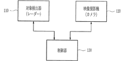
図1は、本発明の実施例による車路認識システムのブロック構成図である。 FIG. 1 is a block diagram of a roadway recognition system according to an embodiment of the present invention.
本発明の実施例による車路認識システムは、走行方向の道路(片道)の全体車路数と、車両が位置している車路を認識する車路認識システムである。 The road recognition system according to the embodiment of the present invention is a road recognition system that recognizes the total number of roads (one way) in the traveling direction and the roads on which the vehicles are located.
このような本発明の実施例による車路認識システムは、車両100に備えて、道路の左側及び/または右側に設けられた固定物10L、10Rの位置を検出する対象検出器110;前記車両100に備えて、道路の路面映像を撮影する映像撮影機120;及び前記対象検出器110及び前記映像撮影機120の信号に基づいて車両100が現在位置している車路を認識する制御器130とを含む。
Such a roadway recognition system according to an embodiment of the present invention includes a
前記対象検出器110は、本発明の実施例では、一例として電波反射波のドップラー効果を利用して固定物及び/または移動体の認知に幅広く利用されているレーダー(またはレーダーセンサ)に形成することができ、他の例としては前記レーダーに相当するレーダースキャナーに形成することができるが、本発明の保護範囲がこれに限定されることと理解してはならない。これとは異なる構成であっても実質的に道路の固定物である中央分離帯及び/またはガードレールの位置を検出できる構成であれば、本発明の技術的な思想が適用可能である。前記対象検出器として前記レーダーの構成及び作用に関しては当業者に自明であるので、さらなる詳細な記載を省略する。
In the embodiment of the present invention, the
前記映像撮影機120は、本発明の実施例では、一例として幅広く利用されているCCD(charge coupled device)を含む映像カメラに形成することができるが、本発明の保護範囲がこれに限定されたことと理解してはならない。これとは異なる構成であっても実質的に道路の路面を撮影できる構成であれば、本発明の技術的な思想が適用可能である。前記映像撮影機として前記カメラの構成及び作用に関しては当業者に自明であるので、さらなる詳細な記載を省略する。
In the embodiment of the present invention, the
前記制御器130は、設定されたプログラムによって動作する一つ以上のマイクロプロセッサーを含んで構成され、前記設定されたプログラムは、後述する本発明の実施例による車路認識方法を行うための一連の命令で形成される。
The
本発明の実施例では、前記制御器130は、車両のマルチメディアを制御するマルチメディア制御システム、及び車両のボディー電装品を制御するボディー制御モジュール(BCM;body control module)に含まれて構成される。または、前記制御器130は、前記マルチメディア制御システム及びボディー制御モジュールを含むことができる。
In an embodiment of the present invention, the
後述する本発明の実施例による車路認識方法において、その一部のプロセスは、カメラと係る前記マルチメディア制御システムによって行われ、他の一部プロセスは、前記レーダーと係るBCMによって行われるようにすることができる。しかし、本発明の保護範囲が後述する実施例によって限定されることと理解してはならない。本発明の実施例における説明とは異なる組み合わせで制御器を実現することができる。 In the road recognition method according to the embodiment of the present invention described later, a part of the process is performed by the multimedia control system related to the camera, and the other part of the process is performed by the BCM related to the radar. can do. However, it should not be understood that the protection scope of the present invention is limited by the examples described below. The controller can be realized by a combination different from the description in the embodiment of the present invention.
以下、本発明の実施例による車路認識方法について、添付した図面を参照して詳細に説明する。 Hereinafter, a method for recognizing a road according to an embodiment of the present invention will be described in detail with reference to the accompanying drawings.
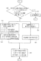
図3は、本発明の実施例による車路認識方法を示したフローチャートである。 FIG. 3 is a flowchart illustrating a road recognition method according to an embodiment of the present invention.
本発明の実施例による車路認識方法は、走行方向の道路の全体車路数及び/または車両が位置している車路を認識するプロセスで形成された車路認識方法である。 A road recognition method according to an embodiment of the present invention is a road recognition method formed by a process of recognizing the total number of roads in a road in a traveling direction and / or a road where a vehicle is located.
このような本発明の実施例による車路認識方法は、レーダー110によって走行方向の左側及び/または右側にある固定物10L、10Rの位置を得る段階(S110);カメラ120によって車両100の前方の路面映像を得る段階(S210);前記左側及び/または右側にある固定物10L、10Rの位置に基づいて走行道路の全体幅Widthを計算する段階(S120);前記路面映像から走行車路の幅Lane_Wを計算する段階(S220);及び前記計算された走行車路の幅Lane_Wと前記走行道路の全体幅Widthに基づいて前記車両が位置している車路Current_Laneを計算する段階(S310);を含むことができる。
In the method for recognizing a road according to the embodiment of the present invention, the
前記固定物の位置を得る段階(S110)は、前記車両100から一定距離の前方に位置した左側及び/または右側にある固定物10L、10Rから反射して受信されたレーダービーム間に形成するレーダービーム間角度を計算する段階;前記車両100から一定距離の前方に位置した前記左側及び/または右側固定物10L、10Rから反射して受信された各レーダービームと前記車両の進行方向との間に形成する左側及び/または右側偏向角度Angle_L、Angle_Rを検出する段階;及び前記レーダービーム間角度、前記左側及び/または右側偏向角度に基づいて前記固定物の位置を計算する段階;を含むことができる。
The step (S110) of obtaining the position of the fixed object is a radar formed between radar beams reflected and received from the fixed
一方、前記固定物の位置を得る段階110は、走行車路にガードレールがない場合、前記車両100から一定距離の前方に位置した左側固定物10Lである中央分離帯から反射して受信されたレーダービームのみを受信して、その位置を計算するようにする。
On the other hand, in the
また、本発明の実施例による車路認識方法は、前記レーダービームが受信されなければ、走行車路の認識を終了する段階(S102、104)を含むことができる。 In addition, the road recognition method according to the embodiment of the present invention may include the step of ending the recognition of the traveling road (S102, 104) if the radar beam is not received.
以下、上述のように構成された本発明の実施例による車路認識方法の作用について、具体的に説明する。 The operation of the road recognition method according to the embodiment of the present invention configured as described above will be specifically described below.
図3に示されているように、制御器130はレーダー110を制御して、車両100が走行している道路の左側及び右側に設けられた固定物である中央分離帯10Lとガードレール10Lがあるかを確認する(S102)。つまり、制御器130はレーダー110を制御してレーダービームを送出して、反射波の受信有無により中央分離帯の固定物10L及び/またはガードレールの固定物10Rがあるかを判断する。
As shown in FIG. 3, the
本発明の実施例において、車両100の左側にある固定物として前記中央分離帯を例として挙げたが、本発明の保護範囲がこれに限定されることと理解してはならない。前記中央分離帯とは異なるものでも、道路の中央を分離するための施設物であって、レーダービームを反射できる施設物であれば、本発明の技術的な思想が適用可能である。
In the embodiment of the present invention, the center separation band is given as an example of a fixed object on the left side of the
また、本発明の実施例において、車両100の右側にある固定物として前記ガードレールを例として挙げたが、本発明の保護範囲がこれに限定されることと理解してはならない。
前記ガードレールとは異なるものでも、道路の最右側を警戒するための施設物であって、前記レーダービームを反射できる施設物であれば、本発明の技術的な思想が適用可能である。
In the embodiment of the present invention, the guard rail is given as an example of a fixed object on the right side of the
The technical idea of the present invention can be applied to any facility that is different from the guardrail and is a facility for guarding the rightmost side of the road and capable of reflecting the radar beam.
前記レーダー110に前記反射波のいずれも受信されなくて、前記制御器130に前記反射波のいずれも入力されなければ、制御器130は前記レーダー110に異常があることと判断するか、または走行車路を認識するための固定物であるガードレールと中央分離帯が全てないことと判断して、本発明の実施例による車路認識のプロセスを終了する(S104)。
If none of the reflected waves are received by the
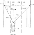
一方、前記レーダー110に前記反射波が受信されれば、制御器130は左側固定物10L 及び右側固定物10Rからそれぞれ反射したレーダービーム反射波と、車両100の進行方向との間に形成する角度Angle_L、Angle_R(図4参照)を検出する(S110)。
On the other hand, when the reflected wave is received by the
制御器130は、前記検出された角度Angle_L、Angle_Rに基づいて前記左側固定物10L及び右側固定物10Rの位置を計算して得ることができる(S110)。
The
また、制御器130は、前記左側固定物10L及び右側固定物10Rからそれぞれ反射したレーダービーム反射波間の角度も検出する(S110)。前記検出されたこれら角度はメモリ(図示せず)に保存されて用いられる。
The
これと共に、制御器130は、前記レーダービーム反射波に基づいて前記左側固定物10L及び右側固定物10Rと前記レーダー110との間の距離Distance_L、Distance_Rを計算する。前記計算された距離Distance_L、Distance_Rはメモリ(図示せず)等に保存されて用いられる。
At the same time, the
上記のように角度Angle_L、Angle_Rが検出されて、距離Distance_L、Distance_Rが計算されたら、制御器130は、下記公式により前記車両100が走行する方向の道路の全体幅Widthを計算して得る。
When the angles Angle_L and Angle_R are detected and the distances Distance_L and Distance_R are calculated as described above, the
Width=(Distance_L×sin(Angle_L))+(Distance_R×sin(Angle_R))
前記角度Angle_L、Angle_R及び距離Distance_L、Distance_R、そして道路の全体幅Widthを求めるプロセスは当業者に自明であるので、本明細書でこれに対する詳細な説明は省略する。
Width = (Distance_L × sin (Angle_L)) + (Distance_R × sin (Angle_R))
A process for obtaining the angles Angle_L, Angle_R, distance Distance_L, Distance_R, and the entire width Width of the road is obvious to those skilled in the art, and a detailed description thereof will be omitted herein.
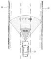
一方、S102段階で左側固定物10L及び右側固定物10Rからレーダービーム反射波があれば、制御器130はカメラ120を制御して、図2に示したように車両100の前方の路面を撮影する。カメラ120が路面を撮影すれば、制御器130はカメラ120から撮影された路面映像を受信する(S210)。
On the other hand, if there is a radar beam reflected wave from the left fixed
前記撮影された路面映像が制御器130に入力されれば、制御器130は入力された路面映像から車路間の幅、つまり、車路幅Lane_Wを計算する(S220)。計算された車路幅Lane_Wはメモリ(図示せず)等に保存されて用いられる。
If the photographed road surface image is input to the
前記のように行って、前記角度Angle_L、Angle_R、距離Distance_L、Distance_R、道路の全体幅Width、及び車路幅Lane_Wが求められたら、制御器130は、これら値に基づいて走行方向の道路(片道)の全体車路数Tatal_Lane、及び車両100が位置している現在位置車路Current_Laneを下記公式により計算して求める(S310)。
When the angle Angle_L, Angle_R, the distance Distance_L, the distance_R, the overall width Width of the road, and the road width Lane_W are obtained as described above, the
Total_Lane=(Width)/(Lane_W)
(Current_Lane−0.5)×Lane_W=Distance_L×sin(Angle_L)
前記全体車路数Tatal_Laneを求める時、割った商の整数値が全体車路数であり、小数点以下は車路に含まれない路肩の幅でありうる。
Total_Lane = (Width) / (Lane_W)
(Current_Lane−0.5) × Lane_W = Distance_L × sin (Angle_L)
When obtaining the total number of roads Tatal_Lane, the integer value of the divided quotient may be the number of whole roads, and the number after the decimal point may be the width of the shoulder not included in the road.
前記説明では左側固定物10L及び右側固定物10Rが全てある場合、つまり、中央分離帯及びガードレールが全てある場合を例に挙げて説明したが、本発明の実施例の他の例としてガードレールはなくて中央分離帯だけがある場合に、全体車路数を計算できないが、現在車両が位置する車路を計算できる。つまり、レーダー110を利用して中央分離帯の位置を確認し、カメラ120を利用して車路幅を求めれば、制御器130は前記中央分離帯の位置から最も近い車路幅から車路番号を順に決めることができる。
In the above description, the case where all of the left side fixed
本発明の実施例の他の例として、前記のように中央分離帯だけがあって、ガードレールがない場合にも、車路番号を順に決められるので、これをナビゲーションに適用すればナビゲーションの性能が向上することができる。 As another example of the embodiment of the present invention, the road number can be determined in order even when there is only a median strip and no guardrail as described above. Can be improved.
したがって、本発明の実施例は、レーダーとカメラを利用して走行道路の全体幅及び車両が位置している車路を認識することができる。このように認識された走行道路の全体車路数及び現在車両が位置している車路の情報は、ナビゲーション及び車路変更システム等に活用されるのは上述の通りである。 Therefore, the embodiment of the present invention can recognize the entire width of the traveling road and the road on which the vehicle is located by using a radar and a camera. As described above, the information on the total number of lanes of the traveling road and the information on the lane where the vehicle is currently located is used for navigation and a lane changing system.
以上、本発明の実施例について詳細に説明したが、本発明の権利範囲はこれに限定されず、次の請求範囲で定義している本発明の基本概念を利用した当業者の種々の変形及び改良形態も本発明の権利範囲に属するものである。 The embodiments of the present invention have been described in detail above, but the scope of the present invention is not limited thereto, and various modifications and variations of those skilled in the art using the basic concept of the present invention defined in the following claims. Improvements are also within the scope of the present invention.
100 車両
110 対象検出器(レーダー)
120 映像撮影機(カメラ)
130 制御器
100
120 Video camera (camera)
130 Controller
Claims (7)
前記対象検出器によって前記固定物の位置を得る段階;
前記映像撮影機によって前記前方の路面映像を得る段階;
前記左側及び右側にある前記固定物の位置に基づいて走行道路の全体幅Widthを計算する段階;
前記路面映像から走行車路の幅Lane_Wを計算する段階;及び
前記計算された走行車路の幅Lane_Wと前記走行道路の全体幅Widthに基づいて前記車両が位置している車路Current_Laneを計算する段階;
を含み、
前記対象検出器はドップラー効果を利用するレーダーであって、
前記固定物の位置を得る段階は、
前記車両から一定距離の前方に位置した左側及び右側の固定物から反射して受信された各レーダービームと前記車両の進行方向との間に形成する左側偏向角度Angle_L及び右側偏向角度Angle_Rを検出する段階を含み、
前記走行道路の全体幅を計算する段階は、
前記反射して受信されたレーダービームから前記左側固定物及び右側固定物と前記レーダーとの間の距離Distance_L、Distance_Rを計算する段階と、
前記計算された左側固定物及び右側固定物と前記レーダーとの間の距離と、前記左側偏向角度及び右側偏向角度と、を利用して前記走行道路の全体幅Widthを得る段階と、を含み、
前記車両が位置している車路Current_Laneを計算する段階は、
前記左側偏向角度Angle_L及び右側偏向角度Angle_R、前記走行道路の全体幅Width、前記左側固定物及び右側固定物と前記レーダーとの間の距離Distance_L、Distance_R、及び前記走行車路の幅Lane_Wを利用して前記車路Current_Laneを計算することを特徴とする、車路認識方法。 Recognize the road on which the vehicle is located by using an object detector that detects the position of fixed objects on the left and right sides of the road in the direction of travel and a video camera that captures the road surface image A way to
Obtaining the position of the stationary object by the object detector;
Obtaining the front road surface image by the video camera;
Calculating an overall width Width of the traveling road based on the positions of the fixed objects on the left and right sides;
Calculating a width Lane_W of a traveling road from the road surface image; and calculating a road Current_Lane where the vehicle is located based on the calculated width Lane_W of the traveling road and the overall width Width of the traveling road. Stage;
Including
The target detector is a radar using the Doppler effect,
Obtaining the position of the fixed object comprises:
A left deflection angle Angle_L and a right deflection angle Angle_R formed between each radar beam reflected and received from the left and right stationary objects positioned in front of the vehicle by a certain distance and the traveling direction of the vehicle are detected. Including stages,
Calculating the overall width of the road;
Calculating distances Distance_L and Distance_R between the left fixed object and the right fixed object and the radar from the reflected and received radar beam;
Obtaining the overall width Width of the traveling road using the calculated distance between the left fixed object and the right fixed object and the radar, and the left deflection angle and the right deflection angle.
The step of calculating the lane Current_Lane where the vehicle is located is as follows:
Using the left deflection angle Angle_L and the right deflection angle Angle_R, the overall width Width of the traveling road, the distances Distance_L and Distance_R between the left fixed object and the right fixed object and the radar, and the width Lane_W of the traveling roadway The road recognition method is characterized by calculating the road Current_Lane.
前記レーダービームが受信されなければ、走行車路の認識を終了する段階をさらに含むことを特徴とする、請求項1に記載の車路認識方法。 The left fixed object is a median strip, and the right fixed object is a guardrail,
The method of claim 1, further comprising a step of ending the recognition of the traveling lane if the radar beam is not received.
下記公式によって計算することを特徴とする、請求項1に記載の車路認識方法。
Width=(Distance_L×sin(Angle_L))+(Distance_R×sin(Angle_R)) Calculating the overall width of the road;
The roadway recognition method according to claim 1, wherein the roadway recognition method is calculated according to the following formula.
Width = (Distance_L × sin (Angle_L)) + (Distance_R × sin (Angle_R))
前記計算された走行道路の全体幅と前記走行車路の幅Lane_Wに基づいて前記走行道路の全体車路数Total_Laneを計算する段階を含むことを特徴とする、請求項3に記載の車路認識方法。 Calculating the roadway on which the vehicle is located,
4. The road recognition according to claim 3, further comprising: calculating a total road number Total_Lane of the travel road based on the calculated overall width of the travel road and the width Lane_W of the travel road. Method.
前記走行道路の全体幅Widthを前記走行車路の幅Lane_Wで割って、割った商の整数値を前記全体車路数Total_Laneとすることを特徴とする、請求項4に記載の車路認識方法。 The step of calculating the total number of roads Total_Lane of the traveling road includes:
5. The road recognition method according to claim 4, wherein the whole width Width of the road is divided by the width Lane_W of the road, and an integer value of the divided quotient is used as the total road number Total_Lane. .
(Current_Lane−0.5)×Lane_W=Distance_L×sinAngle_L
によって計算することを特徴とする、請求項3に記載の車路認識方法。 The step of calculating the lane Current_Lane where the vehicle is located includes the following formula:
(Current_Lane−0.5) × Lane_W = Distance_L × sinAngle_L
The roadway recognition method according to claim 3, wherein the roadway recognition method is calculated by:
車両に備えて、前記道路の路面映像を撮影する映像撮影機;及び
前記対象検出器及び前記映像撮影機の信号から前記車両が位置している車路を認識する制御器を含み、
前記制御器は、設定されたプログラムによって動作する一つ以上のマイクロプロセッサーであって、前記設定されたプログラムは、請求項1乃至6のいずれか一項の方法を行うための一連の命令を含むことを特徴とする、車路認識システム。 An object detector for detecting the position of fixed objects provided on the left and right sides of the road in preparation for the vehicle;
A video camera for capturing a road surface image of the road; and a controller for recognizing a road on which the vehicle is located from signals of the target detector and the video camera;
7. The controller is one or more microprocessors that operate according to a set program, the set program comprising a series of instructions for performing the method of any one of claims 1-6. A road recognition system characterized by this.
Applications Claiming Priority (2)
| Application Number | Priority Date | Filing Date | Title |
|---|---|---|---|
| KR10-2012-0119992 | 2012-10-26 | ||
| KR1020120119992A KR101405193B1 (en) | 2012-10-26 | 2012-10-26 | Driving lane recognition method and system |
Publications (2)
| Publication Number | Publication Date |
|---|---|
| JP2014086071A JP2014086071A (en) | 2014-05-12 |
| JP6242573B2 true JP6242573B2 (en) | 2017-12-06 |
Family
ID=50479752
Family Applications (1)
| Application Number | Title | Priority Date | Filing Date |
|---|---|---|---|
| JP2012270596A Active JP6242573B2 (en) | 2012-10-26 | 2012-12-11 | Roadway recognition method and system |
Country Status (5)
| Country | Link |
|---|---|
| US (1) | US9470788B2 (en) |
| JP (1) | JP6242573B2 (en) |
| KR (1) | KR101405193B1 (en) |
| CN (1) | CN103786729B (en) |
| DE (1) | DE102012224498A1 (en) |
Families Citing this family (47)
| Publication number | Priority date | Publication date | Assignee | Title |
|---|---|---|---|---|
| KR101927155B1 (en) * | 2012-10-19 | 2018-12-10 | 현대자동차 주식회사 | Method and system for recognizing space of shoulder of road |
| DE102013021326A1 (en) * | 2013-12-17 | 2015-06-18 | Valeo Schalter Und Sensoren Gmbh | Method for detecting a marking applied to a ground, driver assistance device and motor vehicle |
| JP6357050B2 (en) * | 2014-08-19 | 2018-07-11 | 日野自動車株式会社 | Driving support system |
| CN104163136A (en) * | 2014-08-26 | 2014-11-26 | 无锡市恒通智能交通设施有限公司 | Intelligent automobile traveling assisting method |
| DE102014223259B4 (en) * | 2014-11-14 | 2021-10-14 | Conti Temic Microelectronic Gmbh | Method for estimating the course of a lane in a lane |
| US10262213B2 (en) | 2014-12-16 | 2019-04-16 | Here Global B.V. | Learning lanes from vehicle probes |
| US9721471B2 (en) | 2014-12-16 | 2017-08-01 | Here Global B.V. | Learning lanes from radar data |
| JP6404722B2 (en) * | 2015-01-21 | 2018-10-17 | 株式会社デンソー | Vehicle travel control device |
| DE102015001386A1 (en) * | 2015-02-04 | 2016-08-04 | Audi Ag | Method for determining a transverse position information of a motor vehicle on a roadway and motor vehicle |
| KR101706455B1 (en) * | 2015-04-15 | 2017-02-27 | 한양대학교 산학협력단 | Road sign detection-based driving lane estimation method and apparatus |
| DE102015007592A1 (en) | 2015-06-16 | 2016-12-22 | Audi Ag | Trajectory-based suspension control |
| US10503983B2 (en) * | 2015-08-19 | 2019-12-10 | Mitsubishi Electric Corporation | Lane recognition apparatus and lane recognition method |
| CN105136153B (en) * | 2015-09-11 | 2018-06-26 | 江苏大学 | A kind of lane line exact position harvester and acquisition method |
| DE102015012362A1 (en) * | 2015-09-19 | 2017-03-23 | GM Global Technology Operations LLC (n. d. Ges. d. Staates Delaware) | A method of assisting a driver of a motor vehicle combination, computer program product, lane departure warning |
| KR101953128B1 (en) * | 2015-10-22 | 2019-05-31 | 현대자동차주식회사 | A vehicle and a method for controlling the same |
| US9878711B2 (en) * | 2015-12-14 | 2018-01-30 | Honda Motor Co., Ltd. | Method and system for lane detection and validation |
| KR101836810B1 (en) * | 2015-12-29 | 2018-03-09 | 아주대학교산학협력단 | Apparatus for detecting carriageway |
| CN105843221B (en) * | 2016-03-09 | 2019-04-12 | 法法汽车(中国)有限公司 | Lane keeping method and radar, Lane Keeping System |
| US10248871B2 (en) * | 2016-03-24 | 2019-04-02 | Qualcomm Incorporated | Autonomous lane detection |
| JP6654087B2 (en) * | 2016-04-11 | 2020-02-26 | 株式会社デンソーウェーブ | Object detection device and object detection program |
| US10048688B2 (en) | 2016-06-24 | 2018-08-14 | Qualcomm Incorporated | Dynamic lane definition |
| KR102078771B1 (en) * | 2016-07-12 | 2020-02-19 | 현대자동차주식회사 | Vehicle, and control method for the same |
| CN107784864A (en) * | 2016-08-26 | 2018-03-09 | 奥迪股份公司 | Vehicle assistant drive method and system |
| EP3324330A1 (en) * | 2016-11-16 | 2018-05-23 | Continental Automotive GmbH | Method for determining a course of lanes, driver assistance system, and vehicle |
| US10989791B2 (en) * | 2016-12-05 | 2021-04-27 | Trackman A/S | Device, system, and method for tracking an object using radar data and imager data |
| KR102295577B1 (en) * | 2017-02-08 | 2021-08-30 | 현대자동차주식회사 | Ecu, autonomous vehicle including the ecu, and method of determing driving lane for the same |
| US10453351B2 (en) * | 2017-07-17 | 2019-10-22 | Aurora Flight Sciences Corporation | System and method for detecting obstacles in aerial systems |
| KR102408743B1 (en) * | 2017-07-27 | 2022-06-14 | 주식회사 에이치엘클레무브 | Method and system for determining whether a vehicle can enter a road |
| US10239451B1 (en) * | 2017-09-05 | 2019-03-26 | GM Global Technology Operations LLC | Systems and methods for providing relative lane assignment of objects at distances from the vehicle |
| KR102421855B1 (en) | 2017-09-28 | 2022-07-18 | 삼성전자주식회사 | Method and apparatus of identifying driving lane |
| JP6663406B2 (en) * | 2017-10-05 | 2020-03-11 | 本田技研工業株式会社 | Vehicle control device, vehicle control method, and program |
| CN109858307A (en) * | 2017-11-30 | 2019-06-07 | 高德软件有限公司 | A kind of Lane detection method and apparatus |
| KR102464607B1 (en) * | 2017-12-27 | 2022-11-08 | 현대자동차주식회사 | Vehicle and controlling method thereof |
| CN108345019A (en) * | 2018-04-20 | 2018-07-31 | 长安大学 | The positioning device and method in a kind of vehicle place track |
| KR102448164B1 (en) * | 2018-07-20 | 2022-09-28 | 현대모비스 주식회사 | Apparatus and method for controlling a vehicle radar |
| CN109445428A (en) * | 2018-10-08 | 2019-03-08 | 北京海纳川汽车部件股份有限公司 | The lane change method, apparatus of automatic driving vehicle and automatic driving vehicle with it |
| CN109435940B (en) * | 2018-11-15 | 2020-11-03 | 北京经纬恒润科技有限公司 | Method, device and system for identifying highway lane |
| CN109348414B (en) * | 2018-11-30 | 2021-03-12 | 中国联合网络通信集团有限公司 | Method and equipment for positioning lane where vehicle is located |
| CN109657641B (en) * | 2018-12-29 | 2021-02-02 | 北京经纬恒润科技股份有限公司 | Method and device for judging main road and auxiliary road of vehicle |
| KR20200090527A (en) * | 2019-01-21 | 2020-07-29 | 현대자동차주식회사 | Apparatus for recognizing lane and method thereof |
| CN110221324B (en) * | 2019-05-28 | 2021-04-27 | 上海车轮互联网服务有限公司 | Data processing method and device for positioning |
| CN110422168B (en) * | 2019-08-08 | 2020-06-16 | 智邮开源通信研究院(北京)有限公司 | Lane recognition system and method and automatic driving automobile |
| CN113227831B (en) * | 2019-11-22 | 2023-01-20 | 驭势(上海)汽车科技有限公司 | Guardrail estimation method based on multi-sensor data fusion and vehicle-mounted equipment |
| US11603094B2 (en) | 2020-02-20 | 2023-03-14 | Toyota Motor North America, Inc. | Poor driving countermeasures |
| US11527154B2 (en) | 2020-02-20 | 2022-12-13 | Toyota Motor North America, Inc. | Wrong way driving prevention |
| DE112021003371T8 (en) * | 2020-06-23 | 2023-06-07 | Denso Corporation | Vehicle position estimating device and driving position estimating method |
| CN111899513A (en) * | 2020-08-11 | 2020-11-06 | 东风汽车集团有限公司 | Driving lane judgment method based on sensing of objects around vehicle |
Family Cites Families (26)
| Publication number | Priority date | Publication date | Assignee | Title |
|---|---|---|---|---|
| JPH05342500A (en) * | 1992-06-11 | 1993-12-24 | Nissan Motor Co Ltd | Car to car distance detecting device |
| US5633642A (en) * | 1993-11-23 | 1997-05-27 | Siemens Aktiengesellschaft | Radar method and device for carrying out the method |
| JPH1031799A (en) * | 1996-07-15 | 1998-02-03 | Toyota Motor Corp | Automatic traveling controller |
| JP3843502B2 (en) * | 1996-09-30 | 2006-11-08 | マツダ株式会社 | Vehicle motion recognition device |
| JPH10325869A (en) * | 1997-05-26 | 1998-12-08 | Honda Motor Co Ltd | Radar device for vehicle and automatic traveling control system using it |
| JP3575352B2 (en) * | 1999-10-25 | 2004-10-13 | 株式会社デンソー | Vehicle position locating device and recording medium |
| JP2002225657A (en) * | 2001-02-06 | 2002-08-14 | Oki Electric Ind Co Ltd | Travel lane detecting system for vehicle |
| GB0111979D0 (en) * | 2001-05-17 | 2001-07-04 | Lucas Industries Ltd | Sensing apparatus for vehicles |
| GB0115433D0 (en) * | 2001-06-23 | 2001-08-15 | Lucas Industries Ltd | An object location system for a road vehicle |
| JP4100269B2 (en) * | 2003-06-17 | 2008-06-11 | 日産自動車株式会社 | Vehicle road shape recognition device |
| KR100559870B1 (en) * | 2003-11-04 | 2006-03-13 | 현대자동차주식회사 | A method for changing traveling lane |
| JP4811201B2 (en) * | 2005-12-06 | 2011-11-09 | 日産自動車株式会社 | Runway boundary line detection apparatus and runway boundary line detection method |
| JP4793094B2 (en) * | 2006-05-17 | 2011-10-12 | 株式会社デンソー | Driving environment recognition device |
| DE102006027326A1 (en) * | 2006-06-13 | 2007-12-20 | Robert Bosch Gmbh | Lane change assistant for motor vehicles |
| US8462988B2 (en) * | 2007-01-23 | 2013-06-11 | Valeo Schalter Und Sensoren Gmbh | Method and system for universal lane boundary detection |
| JP2008273251A (en) * | 2007-04-25 | 2008-11-13 | Toyota Motor Corp | Vehicular alarm device |
| US8457359B2 (en) * | 2008-02-20 | 2013-06-04 | Continental Teves Ag & Co. Ohg | Method and assistance system for detecting objects in the surrounding area of a vehicle |
| JP2009252198A (en) * | 2008-04-11 | 2009-10-29 | Suzuki Motor Corp | Travel environment presuming device, method and program, and traffic lane deviation alarm device and steering assisting apparatus |
| WO2010099789A1 (en) * | 2009-03-04 | 2010-09-10 | Continental Teves Ag & Co. Ohg | Method for automatically detecting a driving maneuver of a motor vehicle and a driver assistance system comprising said method |
| JP5007840B2 (en) * | 2009-05-22 | 2012-08-22 | トヨタ自動車株式会社 | Driving assistance device |
| JP4927908B2 (en) | 2009-05-29 | 2012-05-09 | クラリオン株式会社 | Lane position detection system |
| JP2011048641A (en) * | 2009-08-27 | 2011-03-10 | Toyota Motor Corp | Object detection device and driving support device |
| DE102010033729B4 (en) * | 2010-08-07 | 2014-05-08 | Audi Ag | Method and device for determining the position of a vehicle on a roadway and motor vehicles with such a device |
| JP2012089005A (en) | 2010-10-21 | 2012-05-10 | Honda Elesys Co Ltd | Image processing device and image processing method |
| KR20120044495A (en) * | 2010-10-28 | 2012-05-08 | 주식회사 만도 | Lane recognizing system of vehicle |
| KR20120046543A (en) | 2010-11-02 | 2012-05-10 | 현대자동차주식회사 | Lane recognizing navigation guide system |
-
2012
- 2012-10-26 KR KR1020120119992A patent/KR101405193B1/en active IP Right Grant
- 2012-12-11 JP JP2012270596A patent/JP6242573B2/en active Active
- 2012-12-21 US US13/724,248 patent/US9470788B2/en active Active
- 2012-12-28 CN CN201210599194.2A patent/CN103786729B/en active Active
- 2012-12-28 DE DE102012224498.0A patent/DE102012224498A1/en active Pending
Also Published As
| Publication number | Publication date |
|---|---|
| CN103786729A (en) | 2014-05-14 |
| CN103786729B (en) | 2018-03-23 |
| KR20140053723A (en) | 2014-05-08 |
| US20140118182A1 (en) | 2014-05-01 |
| JP2014086071A (en) | 2014-05-12 |
| KR101405193B1 (en) | 2014-06-27 |
| US9470788B2 (en) | 2016-10-18 |
| DE102012224498A1 (en) | 2014-04-30 |
Similar Documents
| Publication | Publication Date | Title |
|---|---|---|
| JP6242573B2 (en) | Roadway recognition method and system | |
| EP3358302B1 (en) | Travel control method and travel control device | |
| JP6451844B2 (en) | Vehicle position determination device and vehicle position determination method | |
| RU2678599C1 (en) | Route guidance device and route navigation and method of route guidance and route navigation | |
| CN102081861B (en) | On-vehicle device and recognition support system | |
| US10239539B2 (en) | Vehicle travel control method and vehicle travel control device | |
| US10710583B2 (en) | Vehicle control apparatus | |
| CN102396002A (en) | Object detection device | |
| KR102386317B1 (en) | Vehicle and collision avoidance method for the same | |
| JP2007178271A (en) | Own position recognition system | |
| WO2018131062A1 (en) | Travel path recognition device and travel path recognition method | |
| JPWO2020025991A1 (en) | Travel locus correction method, travel control method, and travel locus correction device | |
| JP2019168432A (en) | Own vehicle position estimating device | |
| WO2018030159A1 (en) | Recognition device and recognition method | |
| JP2017009553A (en) | Vehicle location determination device and vehicle location determination method | |
| JP7255345B2 (en) | Driving lane recognition device, driving lane recognition method and program | |
| JP3440956B2 (en) | Roadway detection device for vehicles | |
| WO2017013692A1 (en) | Travel lane determination device and travel lane determination method | |
| KR102630991B1 (en) | Method for determining driving posision of vehicle, apparatus thereof and driving control system | |
| US20190095724A1 (en) | Surroundings monitoring device, surroundings monitoring method, and storage medium | |
| JP6627135B2 (en) | Vehicle position determination device | |
| JP2019070895A (en) | Runway recognizer | |
| JPH03220410A (en) | Position locator for vehicle | |
| JP7167891B2 (en) | Image processing device | |
| EP4130669A1 (en) | Device and method for generating lane information |
Legal Events
| Date | Code | Title | Description |
|---|---|---|---|
| RD03 | Notification of appointment of power of attorney |
Free format text: JAPANESE INTERMEDIATE CODE: A7423 Effective date: 20140811 |
|
| RD04 | Notification of resignation of power of attorney |
Free format text: JAPANESE INTERMEDIATE CODE: A7424 Effective date: 20140929 |
|
| A621 | Written request for application examination |
Free format text: JAPANESE INTERMEDIATE CODE: A621 Effective date: 20150730 |
|
| A131 | Notification of reasons for refusal |
Free format text: JAPANESE INTERMEDIATE CODE: A131 Effective date: 20160531 |
|
| A977 | Report on retrieval |
Free format text: JAPANESE INTERMEDIATE CODE: A971007 Effective date: 20160531 |
|
| A521 | Request for written amendment filed |
Free format text: JAPANESE INTERMEDIATE CODE: A523 Effective date: 20160831 |
|
| RD03 | Notification of appointment of power of attorney |
Free format text: JAPANESE INTERMEDIATE CODE: A7423 Effective date: 20161121 |
|
| A131 | Notification of reasons for refusal |
Free format text: JAPANESE INTERMEDIATE CODE: A131 Effective date: 20170214 |
|
| A521 | Request for written amendment filed |
Free format text: JAPANESE INTERMEDIATE CODE: A523 Effective date: 20170515 |
|
| TRDD | Decision of grant or rejection written | ||
| A01 | Written decision to grant a patent or to grant a registration (utility model) |
Free format text: JAPANESE INTERMEDIATE CODE: A01 Effective date: 20171010 |
|
| A61 | First payment of annual fees (during grant procedure) |
Free format text: JAPANESE INTERMEDIATE CODE: A61 Effective date: 20171108 |
|
| R150 | Certificate of patent or registration of utility model |
Ref document number: 6242573 Country of ref document: JP Free format text: JAPANESE INTERMEDIATE CODE: R150 |
|
| R250 | Receipt of annual fees |
Free format text: JAPANESE INTERMEDIATE CODE: R250 |
|
| R250 | Receipt of annual fees |
Free format text: JAPANESE INTERMEDIATE CODE: R250 |
|
| R250 | Receipt of annual fees |
Free format text: JAPANESE INTERMEDIATE CODE: R250 |
|
| R250 | Receipt of annual fees |
Free format text: JAPANESE INTERMEDIATE CODE: R250 |