WO2018128018A1 - Terminal sans fil, station de base, procédés associés et support lisible par ordinateur non temporaire - Google Patents
Terminal sans fil, station de base, procédés associés et support lisible par ordinateur non temporaire Download PDFInfo
- Publication number
- WO2018128018A1 WO2018128018A1 PCT/JP2017/041820 JP2017041820W WO2018128018A1 WO 2018128018 A1 WO2018128018 A1 WO 2018128018A1 JP 2017041820 W JP2017041820 W JP 2017041820W WO 2018128018 A1 WO2018128018 A1 WO 2018128018A1
- Authority
- WO
- WIPO (PCT)
- Prior art keywords
- rrc
- rat
- state
- ran
- wireless terminal
- Prior art date
Links
- 238000000034 method Methods 0.000 title claims description 46
- 230000007704 transition Effects 0.000 claims abstract description 121
- 238000005516 engineering process Methods 0.000 claims description 19
- 230000011664 signaling Effects 0.000 claims description 11
- 101100113067 Rattus norvegicus Cfi gene Proteins 0.000 claims description 6
- NPPQSCRMBWNHMW-UHFFFAOYSA-N Meprobamate Chemical compound NC(=O)OCC(C)(CCC)COC(N)=O NPPQSCRMBWNHMW-UHFFFAOYSA-N 0.000 claims description 4
- 230000008859 change Effects 0.000 claims description 4
- 238000012545 processing Methods 0.000 description 38
- 238000004891 communication Methods 0.000 description 18
- 230000006870 function Effects 0.000 description 10
- 230000005540 biological transmission Effects 0.000 description 9
- 238000010586 diagram Methods 0.000 description 9
- 230000004044 response Effects 0.000 description 8
- 238000007726 management method Methods 0.000 description 7
- 230000008569 process Effects 0.000 description 7
- 230000001276 controlling effect Effects 0.000 description 6
- 230000006872 improvement Effects 0.000 description 6
- 238000011084 recovery Methods 0.000 description 6
- 241000700159 Rattus Species 0.000 description 5
- 239000013256 coordination polymer Substances 0.000 description 4
- 238000012546 transfer Methods 0.000 description 4
- 238000011161 development Methods 0.000 description 3
- 230000018109 developmental process Effects 0.000 description 3
- 230000009977 dual effect Effects 0.000 description 3
- 230000006399 behavior Effects 0.000 description 2
- 238000006243 chemical reaction Methods 0.000 description 2
- 238000004590 computer program Methods 0.000 description 2
- 238000010295 mobile communication Methods 0.000 description 2
- 102100035354 Guanine nucleotide-binding protein G(I)/G(S)/G(T) subunit beta-1 Human genes 0.000 description 1
- 101001024316 Homo sapiens Guanine nucleotide-binding protein G(I)/G(S)/G(T) subunit beta-1 Proteins 0.000 description 1
- 108010076504 Protein Sorting Signals Proteins 0.000 description 1
- 101150074586 RAN3 gene Proteins 0.000 description 1
- 230000003321 amplification Effects 0.000 description 1
- 238000005352 clarification Methods 0.000 description 1
- 238000013144 data compression Methods 0.000 description 1
- 238000000354 decomposition reaction Methods 0.000 description 1
- 230000006837 decompression Effects 0.000 description 1
- 230000000694 effects Effects 0.000 description 1
- 230000010354 integration Effects 0.000 description 1
- 238000013507 mapping Methods 0.000 description 1
- 230000004048 modification Effects 0.000 description 1
- 238000012986 modification Methods 0.000 description 1
- 230000006855 networking Effects 0.000 description 1
- 238000003199 nucleic acid amplification method Methods 0.000 description 1
- 230000003287 optical effect Effects 0.000 description 1
- 239000013307 optical fiber Substances 0.000 description 1
- 230000009467 reduction Effects 0.000 description 1
- 230000001105 regulatory effect Effects 0.000 description 1
- 230000011218 segmentation Effects 0.000 description 1
- 239000004065 semiconductor Substances 0.000 description 1
- 230000003068 static effect Effects 0.000 description 1
- 230000005641 tunneling Effects 0.000 description 1
- 210000000707 wrist Anatomy 0.000 description 1
Images


Classifications
-
- H—ELECTRICITY
- H04—ELECTRIC COMMUNICATION TECHNIQUE
- H04W—WIRELESS COMMUNICATION NETWORKS
- H04W36/00—Hand-off or reselection arrangements
- H04W36/0005—Control or signalling for completing the hand-off
- H04W36/0055—Transmission or use of information for re-establishing the radio link
- H04W36/0069—Transmission or use of information for re-establishing the radio link in case of dual connectivity, e.g. decoupled uplink/downlink
-
- H—ELECTRICITY
- H04—ELECTRIC COMMUNICATION TECHNIQUE
- H04W—WIRELESS COMMUNICATION NETWORKS
- H04W36/00—Hand-off or reselection arrangements
- H04W36/0005—Control or signalling for completing the hand-off
- H04W36/0011—Control or signalling for completing the hand-off for data sessions of end-to-end connection
- H04W36/0027—Control or signalling for completing the hand-off for data sessions of end-to-end connection for a plurality of data sessions of end-to-end connections, e.g. multi-call or multi-bearer end-to-end data connections
-
- H—ELECTRICITY
- H04—ELECTRIC COMMUNICATION TECHNIQUE
- H04W—WIRELESS COMMUNICATION NETWORKS
- H04W36/00—Hand-off or reselection arrangements
- H04W36/0005—Control or signalling for completing the hand-off
- H04W36/0055—Transmission or use of information for re-establishing the radio link
- H04W36/0069—Transmission or use of information for re-establishing the radio link in case of dual connectivity, e.g. decoupled uplink/downlink
- H04W36/00698—Transmission or use of information for re-establishing the radio link in case of dual connectivity, e.g. decoupled uplink/downlink using different RATs
-
- H—ELECTRICITY
- H04—ELECTRIC COMMUNICATION TECHNIQUE
- H04W—WIRELESS COMMUNICATION NETWORKS
- H04W36/00—Hand-off or reselection arrangements
- H04W36/14—Reselecting a network or an air interface
-
- H—ELECTRICITY
- H04—ELECTRIC COMMUNICATION TECHNIQUE
- H04W—WIRELESS COMMUNICATION NETWORKS
- H04W76/00—Connection management
- H04W76/20—Manipulation of established connections
- H04W76/27—Transitions between radio resource control [RRC] states
-
- H—ELECTRICITY
- H04—ELECTRIC COMMUNICATION TECHNIQUE
- H04W—WIRELESS COMMUNICATION NETWORKS
- H04W36/00—Hand-off or reselection arrangements
- H04W36/14—Reselecting a network or an air interface
- H04W36/144—Reselecting a network or an air interface over a different radio air interface technology
- H04W36/1443—Reselecting a network or an air interface over a different radio air interface technology between licensed networks
-
- H—ELECTRICITY
- H04—ELECTRIC COMMUNICATION TECHNIQUE
- H04W—WIRELESS COMMUNICATION NETWORKS
- H04W84/00—Network topologies
- H04W84/02—Hierarchically pre-organised networks, e.g. paging networks, cellular networks, WLAN [Wireless Local Area Network] or WLL [Wireless Local Loop]
- H04W84/04—Large scale networks; Deep hierarchical networks
- H04W84/042—Public Land Mobile systems, e.g. cellular systems
-
- H—ELECTRICITY
- H04—ELECTRIC COMMUNICATION TECHNIQUE
- H04W—WIRELESS COMMUNICATION NETWORKS
- H04W88/00—Devices specially adapted for wireless communication networks, e.g. terminals, base stations or access point devices
- H04W88/02—Terminal devices
- H04W88/06—Terminal devices adapted for operation in multiple networks or having at least two operational modes, e.g. multi-mode terminals
Definitions
- This disclosure relates to wireless communication systems, and more particularly to reselection or handover between different Radio Access Technologies (RAT).
- RAT Radio Access Technologies
- 5G 5th generation mobile communication system
- 5G is a combination of LTE and LTE-Advanced continuous enhancement / evolution and the introduction of a new 5G air interface (new Radio Access Technology (RAT)).
- the new RAT is, for example, a frequency band higher than the frequency band (eg, 6 GHz or less) targeted for the continuous development of LTE / LTE-Advanced, such as a centimeter wave band of 10 GHz or more and a millimeter band of 30 GHz or more. Support waveband.
- the fifth generation mobile communication system is also called 5G System or Next Generation System (NextGen) System (NG System).
- the new RAT for 5G System is called New Radio (NR), 5G RAT, or NG RAT.
- the new radio access network (Radio Access Network (RAN)) for 5G System is called 5G-RAN or NextGen RAN (NG RAN).
- the new base station in the 5G-RAN ⁇ ⁇ is called NR (NodeB (NR NB) or gNodeB (gNB).
- the new core network for 5G System is called 5G Core Network (5G-CN) or NextGen Core (NG Core).
- a wireless terminal (User Equipment (UE)) connected to 5G System is called 5G UE, NextGen UE (NG UE) or simply UE.
- Formal names such as RAT, UE, radio access network, core network, network entity (node), and protocol layer for 5G System will be determined in the process of standardization.
- LTE Long Term Evolution
- LTE-Advanced Pro LTE +, or enhanced LTE (eLTE).
- EPC Evolved Packet Core
- MME Mobility Management Entity
- S-GW Serving Gateway
- PDN Packet Data Network
- P-GW Packet Data Network Gateway
- bearers for each QoS class and for each PDN connection are RAN (ie, Evolved Universal Terrestrial RAN (E-UTRAN)) and core network (ie, for QoS of Service (QoS) and packet routing. Used in both EPC).
- RAN Evolved Universal Terrestrial RAN
- QoS QoS of Service
- EPS Evolved Packet System
- one or more Evolved Packet System (EPS) bearers are set between the UE and the P-GW in the EPC, and there are multiple QoS classes Service data flows (Service Data Flows (SDFs)) are transferred through one EPS Bearer that satisfies these QoS.
- SDFs Service Data Flows
- the SDF is one or a plurality of packet flows that match an SDF template (i.e., “packet” filters) based on a Policy “and” Charging “Control” (PCC) rule. Also, for packet routing, each packet sent through EPS bearer identifies which bearer (ie, General Packet Radio Service (GPRS) Tunneling Protocol (GTP) tunnel) this packet is associated with (identify ) For information.
- GPRS General Packet Radio Service
- GTP General Packet Radio Service Tunneling Protocol
- radio bearers may be used in 5G-RAN, but it is considered that bearers are not used in 5G-CN and in interfaces between 5G-CN and 5G-RAN.
- PDU flows are defined instead of EPS bearer, and one or more SDFs are mapped to one or more PDU flows.
- the PDU flow between the 5G UE and the user plane termination entity in NG Core i.e., the entity corresponding to P-GW in EPC
- PDU flow is also called QoS flow.
- the association between the 5G UE and the data network is called a PDU session.
- the PDU session is a term corresponding to a PDN connection (PDN connection) of LTE and LTE-Advanced. Multiple PDU flows (or QoS flows) can be set in one PDU session.
- 5G System supports network slicing (see Non-Patent Document 1).
- Network slicing uses Network Function Virtualization (NFV) technology and software-defined networking (SDN) technology to enable the creation of multiple virtualized logical networks on top of a physical network.
- Each virtualized logical network called a network slice or network slice instance, contains logical nodes and functions, and includes specific traffic. And used for signaling.
- 5G-RAN or 5G-CN or both have a Slice Selection Function (SSF).
- the SSF selects one or more network slices suitable for the 5G UE based on information provided by at least one of the 5G UE and 5G-CN.
- Fig. 1 shows the basic architecture of 5G system.
- the UE establishes one or more signaling radio bearers (Signalling Radio Bearers (SRBs)) and one or more data radio bearers (Data Radio Bearers (DRBs)) with the gNB.
- SRBs Signaling Radio Bearers
- DRBs Data Radio Bearers
- 5G-CN and gNB establish a control plane interface and user plane interface for the UE.
- the control plane interface between 5G-CN and gNB ie, RAN
- NG2 interface or NG-c interface transfer of Non-Access Stratum (NAS) information
- NAS Non-Access Stratum
- the user plane interface between 5G-CN and gNB (ie, RAN) is called NG3 interface or NG-u interface, and one or more PDU flows (or QoS flows) packets in the UE's PDU session Used to transfer (packets).
- a new RRC state is introduced in addition to the RRC_CONNECTED state and the RRC_IDLE state (see, for example, Non-Patent Documents 1-5).
- the new RRC state is called the RRC_INACTIVE state or the RRC_INACTIVE_CONNECTED state.
- E-UTRA Evolved Universal Terrestrial Radio Access
- the RRC state of the 5G ⁇ ⁇ System is called the “NR” RRC_CONNECTED state, “NR” RRC_INACTIVE state, and “NR” RRC_IDLE state.
- the RRC state of E-UTRA is referred to as “E-UTRA” RRC_CONNECTED state and “E-UTRA” RRC_IDLE state.
- NR-RRC_CONNECTED state and NR-RRC_IDLE state have the same characteristics as E-UTRA-RRC_CONNECTED state and E-UTRA-RRC_IDLE state, respectively.
- the UE and 5G-RAN maintain the AS context, and the UE location is known by the 5G-RAN at the cell level.
- the mobility of UEs in the NR RRC_CONNECTED state is handled by handover controlled by 5G-RAN.
- the UE when the UE is in NR RRC_IDLE state, the UE and 5G-RAN have released the AS context, the UE location is not known by the 5G-RAN, and the UE location is the location registration area by the 5G-CN. ⁇ Known by level.
- the location registration area corresponds to an LTE tracking area (Tracking Area (TA)).
- TA Tracking Area
- the mobility of UEs in NR RRC_IDLE state is handled by cell reselection controlled by the UE.
- the RRC state of the AS layer is associated with the connection management (NG Connection Management (NG CM)) state of the NAS layer.
- NG CM connection Management
- a UE that is in the NR RRC_CONNECTED state is considered to be in the NG-CM-CONNECTED state in the UE and 5G-CN.
- a UE in the NR RRC_IDLE state is considered to be in the NG-CM-IDLE state in the UE and 5G-CN.
- the NRACTRRC_INACTIVE state is an intermediate state between the NR RRC_CONNETED state and the NR RRC_IDLE state.
- Some features in the NR RRC_INACTIVE state are similar to those in the NR RRC_CONNETED state, while some other features in the NR RRC_INACTIVE state are similar to those in the NR RRC_IDLE state.
- UE and 5G-RAN When UE is in NR RRC_INACTIVE state, UE and 5G-RAN maintain at least part of AS context.
- the AS context maintained by the UE and 5G-RAN for the UE in the NR RRC_INACTIVE state includes, for example, radio bearer configuration and AS security context.
- the 5G-RAN maintains the control plane and user plane connection (i.e., NG2 and NG3 interfaces in FIG. 1) with the 5G-CN for UEs in the NR RRC_INACTIVE state.
- a UE in the NR RRC_INACTIVE state is considered to be in the NG-CM-CONNECTED state in the UE and 5G-CN.
- 5G-CN does not distinguish whether the UE is in the NR RRC_CONNECTED state or the NR RRC_INACTIVE state.
- the mobility of UEs in NR RRC_INACTIVE state is similar to that of UEs in NR RRC_IDLE state. That is, the mobility of the UE in the NR RRC_INACTIVE state is handled by cell reselection controlled by the UE.
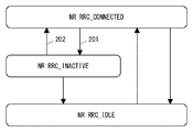
- Figure 2 shows the state transitions between the three currently proposed RRC states.
- the UE can transition between the NR RRC_CONNECTED state and the NR RRC_INACTIVE state (steps 201 and 202).
- the transition between the NR RRC_CONNECTED state and the NR RCC_INACTIVE state is assumed to reuse the RRC connection Suspend and Resume procedures specified in 3GPP Release 13 for LTE.
- AS contexts stored in 5G-RAN for UEs in NR RRC_INACTIVE state can be transferred between RAN nodes (between gNBs).
- the gNB that has received the RRC message (eg, RRC Connection Resume request) from the UE transmits the AS context of the UE from another gNB. It may be fetched (retrieve).
- RRC message eg, RRC Connection Resume request
- the position of the UE in the NR RRC_INACTIVE state is known by 5G-RAN at the level of the newly defined RAN notification area (RAN Notification Area (RNA)).
- the RAN notification area is also referred to as RAN-based Notification Area, RAN paging area, or RAN location update area.
- the RAN notification area (RNA) includes one or more cells, is determined by 5G-RAN, and is set to UE by 5G-RAN.
- a UE in the NR RRC_INACTIVE state does not need to notify (report) that cell reselection has been performed to 5G-RAN even if it moves between cells by cell reselection within the RAN notification area.
- the UE in the NR RRC_INACTIVE state reselects a cell outside the RAN notification area, it requests 5G-RAN to update the RAN notification area.
- FIG. 3 shows an example of UE mobility in the NR RCC_INACTIVE state.
- the UE 301 is in the NR RRC_CONNECTED state (321) in the cell 351 of the gNB 311, is assigned a dedicated radio resource from the gNB 311, and has established dedicated radio bearers (dedicated radio bearers) 322.
- the gNB 311 determines the transition of the UE 301 to the NR RRC_INACTIVE state, sets the RAN notification area 340 to the UE 301, and transmits an RRC message (e.g., RRC Suspend message) to the UE 301 (323).
- the UE 301 enters the NR RRC_INACTIVE state from the NR RRC_CONNECTED state (324).
- the UE 301 in the NR RRC_INACTIVE state executes the cell reselection procedure, and reselects the cell 352 of the gNB 312 (325). Since cell 352 is included in RAN notification area 340 set for UE 301, UE 301 does not report cell reselection (that is, update of UE location information) to 5G-RAN (e.g., cell 352 or gNB 312). The UE 301 moves further and reselects the cell 353 of the gNB 313 (326). Since the cell 353 is not included in the RAN notification area 340 set for the UE 301, the UE 301 transmits a RAN notification area update request (327) to the gNB 313.
- cell reselection that is, update of UE location information
- 5G-RAN e.g., cell 352 or gNB 312
- the UE 301 moves further and reselects the cell 353 of the gNB 313
- the request (327) may be transmitted using an RRC message (e.g., RRC Resume Request message) requesting a transition from NR RRC_INACTIVE to NR RRC_CONNECTED.
- the gNB 313 acquires the AS context of the UE 301 from the gNB 311 and re-establishes PacketPackData Convergence Protocol (PDCP) and Radio Link Control (RLC) for the radio bearer using the acquired AS context. Then, the gNB 313 transmits an RRC message (e.g., RRC resume message) to transition the UE 301 to the NR RRC_CONNECTED state.
- RRC message e.g., RRC Resume Request message
- the UE 301 In response to the instruction from the gNB 311, the UE 301 enters the NR RRC_CONNECTED state from the NR RRC_INACTIVE state in the cell 353 (329). The UE 301 can transmit and receive data using dedicated radio bearers 330.
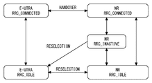
- Non-Patent Document 2 describes the UE state transition diagram shown in FIG.
- Non-Patent Document 2 describes that an inter-RAT handover procedure for existing RATs (legacy RATs) can be used for transition between the NR RRC CONNECTED state and the E-UTRA RRC_CONNECTED state, and that the NR RRC IDLE state and the E-U
- an inter-RAT cell reselection procedure for existing RATs can be used for transitions between UTRA RRC_IDLE states.
- Non-Patent Document 2 further proposes that an inter-RAT cell reselection procedure can be used for transition from the NR RRC_INACTIVE state to the E-UTRA RRC_IDLE state.
- 3GPP TR 23.799 V14.0.0 2016-12 “3rd Generation Partnership Project; Technical Specification Group Services Services and System Aspects; Study On Architecture Architecture for Release Next Generation 14 (Release 14), December 2016 3GPP R2-168077, NTT DOCOMO, INC., “UE state transition diagram for NR”, 3GPP TSG-RAN WG2 Meeting # 96, Reno, USA 14th-18th November 2016
- Non-Patent Document 2 proposes that when a UE in an NR RRC_INACTIVE state moves from an NR cell to an E-UTRA cell, the UE transitions to an E-UTRA RRC_IDLE state using a cell reselection procedure. Yes. However, it is not clear under what conditions the UE makes this state transition. In addition, it may not be desirable to always transition to the E-UTRA RRC_IDLE state when a UE in the NR RRC_INACTIVE state moves to the E-UTRA cell.
- the eNB providing the E-UTRA cell is an eNB improved for interworking with NG System (eg, E-UTRA-NR Dual Connectivity (ENDC))
- the eNB is 5G-CN May be connected, and a direct inter-base station interface between the eNB and the gNB may be used.
- the eNB may be able to obtain the NR AS context for the UE in the NR RRC_INACTIVE state from the 5G-RAN and derive the E-UTRA AS context from the obtained NR AS context.
- one of the objects that the embodiments disclosed herein intend to achieve is to provide an apparatus, a method, and a program that contribute to the improvement of UE state transition between the NRCRRC state and the E-UTRA RRC state. Is to provide. It should be noted that this object is only one of the objects that the embodiments disclosed herein intend to achieve. Other objects or problems and novel features will become apparent from the description of the present specification or the accompanying drawings.
- a wireless terminal includes at least one transceiver and at least one processor.
- the at least one processor supports a first Radio Access Technology (RAT) and has an interface with a first core network (CN), one or more cells of a first radio access network (RAN), and
- the at least one transceiver is configured to be controlled by one or more cells of the second RAN that supports the second RAT.
- the at least one processor controls state transition of the wireless terminal between an RRC_CONNECTED state of the first RAT, an RRC_INACTIVE state of the first RAT, and an RRC_IDLE state of the first RAT, and
- the wireless terminal is configured to control state transition between the RRC_CONNECTED state of the second RAT and the RRC_IDLE state of the second RAT.
- the at least one processor further has a non-access-stratum (NAS) connection with the first CN and the wireless terminal is in the RRC_INACTIVE state of the first RAT in the first RAN.
- NAS non-access-stratum
- a base station supporting the second Radio Access Technology includes a memory and at least one processor coupled to the memory.
- the at least one processor is configured to transmit an information element in a cell of the base station for a wireless terminal to determine whether the base station supports a particular RRC state transition.
- the specific RRC state transition includes a state transition of the wireless terminal from the RRC_INACTIVE state of the first RAT to the RRC_CONNECTED state of the second RAT.
- a method in a wireless terminal includes: (a) the wireless terminal in the RRC_CONNECTED state of the first RAT, the RRC_INACTIVE state of the first RAT, and the RRC_IDLE state of the first RAT. Controlling state transition; (b) controlling state transition of the wireless terminal between the RRC_CONNECTED state of the second RAT and the RRC_IDLE state of the second RAT; and (c) the wireless terminal
- the wireless terminal is the cell of the second RAN.
- NAS Non-Access Stratum
- a method in a base station supporting the second Radio Access Technology (RAT) is an information element for a wireless terminal to determine whether or not the base station supports a specific RRC state transition.
- the specific RRC state transition includes a state transition of the wireless terminal from the RRC_INACTIVE state of the first RAT to the RRC_CONNECTED state of the second RAT.
- the program includes a group of instructions (software code) for causing the computer to perform the method according to the third or fourth aspect described above when read by the computer.
- the plurality of embodiments described below can be implemented independently or in appropriate combinations.
- the plurality of embodiments have different novel features. Therefore, these multiple embodiments contribute to solving different purposes or problems and contribute to producing different effects.
- a plurality of embodiments shown below are described mainly for a 3GPP system that supports UE mobility between E-UTRA and 5G RAT. However, these embodiments may be applied to other wireless communication systems that support UE mobility between multiple RATs.
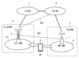
- FIG. 5 shows configuration examples of wireless communication networks according to some embodiments including this embodiment.
- the wireless communication network includes UE2, 5G-RAN3, 5G-CN4, E-UTRAN6, and EPC7.
- the 5G-CN4 includes control plane network functions (Control Plane Network Functions (CP NFs)) and user plane network functions (User Plane Network Functions (UP NFs)) not shown.
- the 5G-CN 4 may provide a plurality of network slices.
- the plurality of network slices are distinguished by, for example, services or use cases provided to the UE on each network slice.
- Use cases include, for example, broadband communication (enhanced Mobile Broad Band: eMBB), high-reliability / low-delay communication (Ultra Reliable and Low Latency Communication: URLLC), and multi-connection M2M communication (massive Machine Type Communication: mMTC).
- 5G-RAN3 includes a plurality of gNBs including gNB1.
- the gNB 1 operates at least one 5G cell 11.
- gNB1 is connected to 5G-CN4, communicates with the control plane node (or CP NF (s)) in 5G-CN4 via the control plane interface (eg, NG2 interface), and the user in 5G-CN4 Communicates with a plain node (or UP NF (s)) via a user plane interface (eg, NG3 interface).
- GNB1 may support one or more network slices.
- one or more network slices may be supported or usable in the 5G cell 11 of gNB1.
- the 5G-RAN3 is in the 5G-CN4 network slice selected for UE2 (referred to as a Core Network (CN) slice) to provide end-to-end network slicing to UE2. Assign the associated RAN slice and radio slice to UE2.
- CN Core Network
- Each RAN slice provides infrastructure storage and processing resources in 5G-RAN3 including gNB1.
- Each radio slice provides radio resources including time resources, frequency resources, code resources, signal sequence resources, or spatial resources, or any combination thereof.
- EPC7 is connected to 5G-CN4. Specifically, one or more nodes in the EPC 7 are connected to one or more nodes in the 5G-CN 4 via a control plane interface.
- the MME in the EPC 7 may communicate with the control plane node (or CP NF (s)) in the 5G-CN 4 via the control plane interface.
- one or more nodes in the EPC 7 may communicate with a user plane node (or UP ⁇ ⁇ NF (s)) in the 5G-CN 4 via a user plane interface. That is, the EPC 7 is enhanced to perform interworking with a 5G-System including 5G-CN4, and may be called eEPC.
- E-UTRAN6 includes a plurality of eNBs including eNB5.
- the LTE eNB 5 operates at least one E-UTRA (LTE) cell 51.
- the eNB 5 is connected to the EPC 7 and communicates with the control plane node (eg, MME) in the EPC 7 via the control plane interface (eg, S1-MME interface), and the user plane node (eg, S in the EPC 7).
- -GW control plane interface
- user plane interface eg, S1-U interface
- the eNB 5 may be connected to 5G-CN4.
- the eNB 5 may have an interface 501 with the 5G-CN 4. That is, the eNB 5 may communicate with the control plane node (or CP NF (s)) in the 5G-CN4 via the control plane interface (eg, NG2 interface), or the user plane in the 5G-CN4. -It may communicate with a node (or UP NF (s)) via a user plane interface (eg, NG3 interface).
- eNB5 is improved (hanced) so that it may be connected with 5G-CN4, and may be called eLTE
- the 5G-CN 4 may set up virtualized network slices (CN slices) that provide logical EPC nodes and EPC functions.
- CN slices virtualized network slices
- E-UTRAN 6 including LTE eNB 5 and 5G-RAN 3 including gNB 1 may be connected to the same CN slice. Instead, the E-UTRAN 6 and the 5G-RAN 3 may be connected to different CN slices.
- the LTE eNB 5 may be connected to the gNB 1 by the direct base station interface 502 (e.g., X3 interface).
- the direct inter-base station interface 502 may be used for signaling between the eNB 5 and the gNB 1 and / or user packet transfer. However, the direct inter-base station interface 502 between the eNB 5 and the gNB 1 may not exist.
- UE2 supports both E-UTRA (LTE RAT) and 5G RAT.
- UE2 has the ability to connect to LTE systems including E-UTRAN6 and EPC7 (E-UTRA-EPC-connected), and connects to 5G systems including 5G-RAN3 and 5G-CN4 (NR-5G-CN -connected) ability. Further, when the E-UTRAN 6 is connected to the 5G-CN 4, the UE 2 has the ability to connect to the 5G-CN 4 via the E-UTRAN 6 (E-UTRA-5G-CN-connected).
- the UE2 is configured to operate in 5G-RAN3 cells that support 5G RAT.
- the UE 2 uses one or more 5G cells 11 provided by one or more gNB 1 for uplink and downlink communication.
- UE2 supports multiple NR RRC states including NR RRC_CONNECTED state, NR RRC_INACTIVE state, and NR RRC_IDLE state.
- the 5G-RAN3 (gNB1) and the UE2 control the state transition of the UE2 between a plurality of NR ⁇ RRC states including the NR RRC_CONNECTED state, the NR RRC_INACTIVE state, and the NR RRC_IDLE state.
- gNB1 transmits RAN notification area information to UE2 with an RRC message (eg, RRC Connection Release, RRC Connection Suspend, or RRC Connection Deactivate) when transitioning UE2 from NR RRC_CONNECTED state to NR RRC_INACTIVE state,
- RRC message eg, RRC Connection Release, RRC Connection Suspend, or RRC Connection Deactivate
- a RAN notification area is set in UE2.
- the RAN notification area includes one or more cells provided by one or more gNB1, and UE2 enters the NR RRC_INACTIVE state in response to receiving the RRC message from gNB1.
- UE2 in the NR RRC_INACTIVE state moves between cells by UE2-driven cell reselection, and does not need to report cell reselection (that is, update of UE location information) in the RAN notification area to 5G-RAN3.
- UE2 requests the gNB of the reselected 5G cell to update the RAN notification area (or the set RAN notification Notify gNB1B that the area has been exited).
- the reselected gNB of the 5G cell determines a new RAN notification area for UE2, and sets the determined RAN notification area to UE2. That is, as already described, the position of UE2 in the NR RRC_INACTIVE state is known to 5G-RAN3 at the RAN notification area level.
- the RAN notification area includes one or more cells, is determined by 5G-RAN3, and is set to UE2 by 5G-RAN3.
- the RAN notification area is also referred to as RAN-based Notification Area, RAN paging area, or RAN location update area.
- the RAN notification area information may include at least information indicating, for example, which cells are included in the RAN notification area. Furthermore, an identifier (e.g., area number) may be assigned to the RAN notification area. Further, the relationship between the identifier (e.g., RNA ID) of the RAN notification area and the cell (group) included therein may be uniquely determined within a predetermined area. In this case, the RAN notification area information may include an identifier of the RAN notification area and information of cells to be included (e.g., cell identifier).
- the gNB 1A may broadcast the RAN notification area information in its own cell 11A.
- the RAN notification area information may include a plurality of RAN notification areas, each of which is given a condition (e.g., bag category, type), and UE 2 may select the RAN notification area corresponding to itself.
- the conditions include, for example, the slice category or slice type (eg, Slice / Service Type: SST) of the network slice used (or desired) by UE2, the category or type of the terminal, the reception quality of UE2, or the coverage level based thereon , UE2 movement characteristics (eg, UE UE speed, whether it is a stationary terminal or not), or any combination thereof.
- RAN notification area set in UE2 may be the same as UE2's location registration area (area corresponding to i.e., LTE tracking area (TA)).
- TA LTE tracking area
- an individual RAN notification area i.e. Slice specific RNA
- at least one of the plurality of RAN notification areas may be the same as the location registration area (e.g., TA).
- an information element eg, RanAreaCellList Information Element (IE)
- IE RanAreaCellList Information Element
- the RAN notification area information may include an information element (e.g., TrackingAreaCode IE) indicating a TA identifier instead of an information element indicating a cell list (that is, Choice).
- an information element e.g., TrackingAreaCode IE
- gNB1 may select one of RanAreaCellList IE and TrackingAreaCode IE to indicate the RAN notification area.
- the gNB 1A configures the RAN notification area information (eg, the identifier of the RAN notification area and the RAN notification area) from other gNBs (eg, gNB1B).
- the other gNB may be a gNB that manages a cell belonging to another RAN notification area different from the RAN notification area to which the cell (e.g., cell 11A) of the gNB 1A belongs.
- the information regarding the RAN notification area received from the other gNB may be information regarding another RAN notification area different from the RAN notification area to which the cell (e.g., cell 11A) of the gNB 1A belongs.
- UE2 may select or actually use the RAN notification area based on the network slice with the highest priority.
- the RAN notification area may be selected based on the network slice.
- UE2 may select a RAN notification area on the basis of the network slice contained in the high rank of the list
- RAN notification area in which the individual information (e.g., identifier, category, or type) of the network slice is not specified may be included in the RAN notification area information.
- the default RAN notification area may be a RAN notification area that is effective for the UE 2 without depending on the network slice, or other than the network slice that is explicitly notified by the RAN notification area information.
- the RAN notification area may be effective for the network slice.
- UE2 transmits a location information update request to gNB1 as long as the cell after cell reselection is included in at least one of the plurality of RAN notification areas. You don't have to.
- gNB1 notifies UE2 of the value of a predetermined timer that triggers the transition to the RRC_INACTIVE state, and makes UE2 the transition to the RRC_INACTIVE state based on the timer value and the corresponding timer. It may be executed. For example, the UE 2 in the RRC_CONNECTED state may restart the timer every time user data is transmitted or received (that is, reset and restart the timer), and transition to the RRC_INACTIVE state when the timer expires.
- UE2 is configured to operate in E-UTRAN6 cells that support E-UTRA.
- the UE 2 uses one or more E-UTRA cells 51 provided by one or more eNBs 5 for uplink and downlink communication.
- UE2 supports E-UTRA RRC_CONNECTED state and E-UTRA RRC_IDLE state.
- the E-UTRAN 6 (eNB 5) and the UE 2 control the state transition of the UE 2 between the E-UTRA RRC_CONNECTED state and the E-UTRA RRC_IDLE state.
- UE2 (eg, controller in UE2) according to the present embodiment is UE2 when UE2 is in NR RRC_INACTIVE state in 5G-RAN3 and has a Non-Access Stratum (NAS) connection with previous 5G-CN4.
- E-UTRAN 6 has an interface (ie, 5 interface 501 or interface 502 or both) with at least one of 5G-CN4 and 5G-RAN3 when moving to cell 51 of E-UTRAN6 And it is comprised so that the RRC state transition operation
- the state in which UE2 has a Non-Access-Stratum (NAS) connection with 5G-CN4 corresponds to the NG-CM-CONNECTED state.
- NAS Non-Access-Stratum
- 5G-RAN3 UE2 or eNB5 that operates the UE5G system (ie, 5G- Depending on whether interworking (eg, E-UTRA-NR Dual Connectivity (ENDC)) with CN4 or 5G-RAN3 or both) is configured to change the RRC state transition behavior of UE2.
- interworking eg, E-UTRA-NR Dual Connectivity (ENDC)
- the E-UTRA cell 51 or the eNB 5 that operates the same supports the interworking with the 5G system.
- the E-UTRA cell 51 or the eNB 5 supports the UE 2 with the Multi-system using the LTE system and the 5G system. Having at least one of Connectivity (eg, Dual Connectivity), Seamless Mobility (eg, handover), or UE AS context acquisition (fetch / retrieve), or providing these functions It may mean that there is.
- UE2 may perform the state transition described below. If UE2 (eg, controller in UE2) moves to cell 51 of E-UTRAN6, if E-UTRAN6 has an interface with at least one of 5G-CN4 and 5G-RAN3, UE2 is transitioned from the NR RRC_INACTIVE state to the E-UTRA RRC_CONNECTED state (eg, E-UTRA-EPC-connected mode or E-UTRA-5G-CN-connected mode).
- E-UTRA RRC_CONNECTED state eg, E-UTRA-EPC-connected mode or E-UTRA-5G-CN-connected mode.
- the UE 2 tries to make a transition from the NR RRC_INACTIVE state to the E-UTRA RRC_CONNECTED state.
- UE2 moves to cell 51 of E-UTRAN6, if E-UTRAN6 has no interface with either 5G-CN4 or 5G-RAN3, UE2 Transition from the NR RRC_INACTIVE state to the E-UTRA RRC_IDLE state (eg, E-UTRA-EPC-idle mode or E-UTRA-5G-CN-idle mode).
- the UE 2 tries to make a transition from the NRCRRC_INACTIVE state to the E-UTRA RRC_IDLE state.
- the process performed by the controller in the UE 2 described above may be a process of the AS layer (e.g., RRC sublayer) of the UE 2. Further, the processing performed by the controller may be processing of a plurality of sublayers (e.g., RRC, PDCP, RLC,, and MAC sublayer) in the AS layer. Furthermore, in the inter-RAT mobility from NR of UE2 to E-UTRA, notification from the AS layer of UE2 to the NAS layer of UE2 is necessary. That is, the process performed by the controller in UE2 described above may be the process of the AS layer and the NAS layer of UE2.
- the AS layer e.g., RRC sublayer
- a plurality of sublayers e.g., RRC, PDCP, RLC,, and MAC sublayer
- a notification indicating (or requesting) switching from NR to E-UTRA may be sent to the NAS layer of UE2.
- a notification indicating (or requesting) the release of the NR UE Context may be made to the NAS layer of UE2.
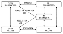
- FIG. 6 is an example of an RRC state transition diagram of UE2.
- UE2 moves to cell 51 of E-UTRAN6 when UE2 is in the NR RRC_INACTIVE state in 5G-RAN3, if UE2 or eNB5 that operates this moves to 5G system (ie, 5G-CN4 or If interworking with 5G-RAN3 or both) is supported, an attempt is made to enter the E-UTRA RRC_CONNECTED state by the RRC connection resumption procedure (601).
- the cell reselection procedure may Attempt to enter state (602).
- the E-UTRAURRC_CONNECTED state is the first sub-state (mode) in which a full RRC connection is maintained, and a lightweight RRC connection compared to a full RRC connection for the purpose of reducing signaling. May be included in a second sub-state (mode) in which is maintained. This second sub-state is called lightly connected mode, for example.
- the state transition in step 601 in FIG. 6 may be a transition from the NR RRC_INACTIVE state to the second sub-state in the E-UTRA RRC_CONNECTED state.
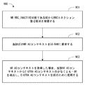
- FIG. 7 is a flowchart showing an example of operation of UE 2 (processing 700).
- step 701 when UE2 detects an E-UTRA cell meeting the cell reselection criteria while UE2 is in the NR RRC_INACTIVE state, the detected E-UTRA cell 51 supports interworking with the 5G system. It is determined whether or not. If the detected E-UTRA cell 51 supports interworking with the 5G system, the UE 2 attempts a transition to the E-UTRAURRC_CONNECTED state in the E-UTRA cell 51 (step 702).
- the UE 2 may determine whether or not the detected E-UTRA cell 51 is provided by the eNB 5 having an interface with the 5G-CN 4 or the 5G-RAN 3 or both. For example, the UE 2 receives a predetermined information element transmitted from the eNB 5 in the E-UTRA cell 51 in order to determine whether the E-UTRA cell 51 or the eNB 5 supports a specific RRC state transition. Also good.
- the specific RRC state transition includes a state transition from the NR RRC_INACTIVE state to the E-UTRA RRC_CONNECTED state.
- the information element may explicitly or implicitly indicate whether 5G support is provided in the E-UTRA cell 51. In other words, the information element may explicitly or implicitly indicate that a particular RRC state transition is supported. In addition or alternatively, the information element includes whether the eNB 5 has an interface with at least one of the 5G-RAN3 and the 5G-CN4 (or the eNB5 has a 5G system (ie, 5G-CN4 or 5G- Whether or not to support interworking with RAN3 or both) may be explicitly or implicitly indicated. In some implementations, the information element may be transmitted with system information. Alternatively, the information element may be embedded in the cell identifier.
- the information element may be a Non-Access Stratum (NAS) information element included in the system information.
- NAS Non-Access Stratum
- the AS layer of UE2 may notify the NAS information element to the NAS layer, and the NAS layer may perform processing necessary for inter-RAT cell reselection in response thereto.
- FIG. 8 is a flowchart showing an example of operation of UE 2 (process 800).
- the processing in step 801 is the same as that in step 701 in FIG. That is, in step 801, when UE2 detects an E-UTRA cell that meets the cell reselection criteria while UE2 is in the NR RRC_INACTIVE state, UE2 detects that the detected E-UTRA cell 51 performs interworking with the 5G system. Determine if it is supported. If the detected E-UTRA cell 51 does not support interworking with the 5G system, UE2 attempts to transition to the E-UTRA RRC_IDLE state (step 802).
- UE2 may execute the location update procedure (i.e., Tracking Area Update (TAU) procedure) to EPC7 via E-UTRAN6 after transitioning to E-UTRA RRC_IDLE state.
- TAU Tracking Area Update
- ISR IdleImode Signalling Reduction
- the UE is registered with both two mobility management entities (i.e., Serving GPRS Support Node (SGSN) and MME) corresponding to the two UTRA and E-UTRA.
- SGSN Serving GPRS Support Node
- MME Mobility Management Entity
- the UE If the ISR is activated, the UE must be outside the two location registration areas (ie, Routing Area (RA) and TrackingTrackArea (s) (TA (s))) registered in the network. Further, reselection can be performed between UTRAN and E-UTRAN without performing location registration processing (ie, RA Update (RAU), TAU). Also for reselection between E-UTRAN6 and 5G-RAN3, ie for reselection between EPC7 and 5G-CN4 and between E-UTRAN6 and 5G-RAN3 under 5G-CN4 An ISR may be introduced. In this case, step 803 may be omitted.
- RA Update RA Update
- FIG. 9 is a flowchart showing an example of operation of the eNB 5 (processing 900).
- the eNB 5 receives an RRC connection recovery request (e.g., RRC Connection Resume Request) from the UE2 in the NR RRC_INACTIVE state.
- RRC connection recovery request e.g., RRC Connection Resume Request
- a new RRC message e.g., ConnectionRRCConnectionResumeRequest-NR, RRCConnectionResumeRequest-InterRAT (IRAT)
- IRAT Inter-RAT RRC Conection Resume from NR to E-UTRA.
- mobility information indicating Inter-RAT RRC Connection Resume from NR to E-UTRA may be included in the RRC connection recovery request.
- the mobility information is, for example, information (eg, interRAT-mobility, interRAT-resume, resumeFromNR) indicating that the RRC connection recovery factor (resume cause) is a transition from the NR RRC_INACTIVE state to the E-UTRA RRC_CONNECTED state. It may include at least one of information on the NR cell (eg, cell identifier, carrier frequency) transitioned to the NR RRC_INACTIVE state, and information on the RAN notification area. Note that since the resume ID used in E-UTRA (LTE) is 40 bits long, the resume ID assigned to the UE in the RRC_INACTIVE state of the NR may also be 40 bits long. Alternatively, when the NR resume ID is larger than 40 bits, the UE 2 may transmit a truncated resume ID having a length of 40 bits derived from the NR resume ID ⁇ to the eNB 5 as an RRC connection recovery request.
- information eg, interRAT-mobility, interRAT-resume,
- the eNB 5 requests the 5G-RAN 3 for the NR ⁇ AS context of the UE 2 in response to the reception of the RRC connection recovery request.
- the eNB 5 derives at least a part of the E-UTRA AS context from the NR AS context and uses the E-UTRA AS context for UE2 (step 903).
- eNB5 permits the transition from NR
- RRC connection resume ⁇ ⁇ ⁇ ⁇ procedure cannot be used as it is.
- layer 2 reconfiguration including AS security settings (e.g., PDCS re-establishment, RLC re-establishment, MAC reset), that is, E-UTRA setting as layer 2.
- the eNB 5 may respond to the RRC connection recovery request (e.g., “RRC Connection Resume Request) from the UE 2 with RRC Connection Setup. That is, the eNB 5 may transmit radio resource setting information (e.g., “Radio” resource “configuration”) necessary for establishing a new RRC connection for E-UTRA to the UE 2.
- radio resource setting information e.g., “Radio” resource “configuration”
- UE2 completes RRC connection establishment and reports it to eNB5 (e.g., RRC Connection Setup Complete). Instead, UE2 may transmit RRC
- FIG. 10 is a sequence diagram illustrating an example of operation of the eNB 5 (processing 1000).
- eNB5 sends the information element regarding 5G support to UE2.
- the information element may indicate whether or not interworking with the 5G system (i.e., 5G-CN4 or 5G-RAN3 or both) is provided in the E-UTRA cell 51.
- the information element may be embedded in the cell identifier. Thereby, UE2 can determine the presence or absence of provision of 5G support in the cell 51 only by receiving the cell identifier of the cell 51.
- the information element may be a NAS information element included in the system information.
- eNB5 enables UE2 to determine whether the interworking with a 5G system is supported in the E-UTRA cell 51.
- FIG. the eNB 5 allows the UE 2 to determine whether or not the transition from the NR RRC_INACTIVE state to the E-UTRA RRC_CONNECTED state is possible (or permitted) in the E-UTRA cell 51. .
- the UE 2 is in the NR RRC_INACTIVE state in the 5G-RAN3 and has a Non-Access Stratum (NAS) connection with the 5G-CN4.
- NAS Non-Access Stratum
- UE2 moves to cell 51 of E-UTRAN6, whether or not E-UTRAN6 has an interface (ie, interface 501 or interface 502 or both) with at least one of 5G-CN4 and 5G-RAN3
- the RRC state transition operation of UE2 is changed.
- UE2 can optimize the state transition of UE2 between the NR RRC state and the E-UTRA RRC state. Therefore, this embodiment can contribute to the improvement of UE state transition between the NR RRC state and the E-UTRA RRC state.
- the present embodiment provides a modification of the operation of UE2 described in the first embodiment.
- a configuration example of the wireless communication network of the present embodiment is the same as that shown in FIG.
- UE2 (eg, controller in UE2) according to the present embodiment is UE2 when UE2 is in NR RRC_INACTIVE state in 5G-RAN3 and has a Non-Access Stratum (NAS) connection with previous 5G-CN4.
- NAS Non-Access Stratum
- the system information transmitted from the eNB 5 in the E-UTRA cell 51 includes information on the interworking support (eg, multi-connectivity support, inter-RAT seamless mobility support, UE context fetch / retrieve support). Whether or not the interworking is supported by the E-UTRA cell 51 or the eNB 5 may be determined. Instead, UE2 is based on whether the system information transmitted from eNB5 in E-UTRA cell 51 includes information on 5G-CN4 (eg, identifier of node (NF) of 5G-CN4). Thus, the interworking support by the E-UTRA cell 51 or the eNB 5 may be determined.
- the interworking support eg, multi-connectivity support, inter-RAT seamless mobility support, UE context fetch / retrieve support.
- information regarding the E-UTRA cell 51 that supports (or provides) the interworking includes system information or dedicated signaling (eg, dedicated (RRC) may be sent to UE2.
- RRC dedicated
- the UE 2 is included in the cell that supports (or provides) the inter-working target E-UTRA cell 51 based on information on the E-UTRA cell 51 that supports the inter-working. Whether or not the interworking is supported by the E-UTRA cell 51 or the eNB 5 may be determined based on whether or not it exists.
- E-UTRA cell 51 or eNB5 supports interworking with 5G system
- UE2 transitions from NR RRC_INACTIVE state to NR RRC_CONNECTED state and then to E-UTRA RRC_CONNECTED state by inter-RAT handover procedure enter.
- the E-UTRA cell 51 or eNB5 does not support interworking with the 5G system
- UE2 enters the E-UTRACRRC_IDLE state by the cell reselection procedure. Thereby, UE2 can optimize the state transition of UE2 between the NR RRC state and the E-UTRA RRC state. Therefore, this embodiment can contribute to the improvement of UE state transition between the NR RRC state and the E-UTRA RRC state.
- FIG. 12 is a block diagram illustrating a configuration example of the eNB 5 according to the above-described embodiment.
- the configuration of gNB1 may be the same as that shown in FIG.
- eNB 5 includes Radio Frequency transceiver 1201, network interface 1203, processor 1204, and memory 1205.
- the RF transceiver 1201 performs analog RF signal processing to communicate with NG UEs including UE2.
- the RF transceiver 1201 may include multiple transceivers.
- RF transceiver 1201 is coupled to antenna array 1202 and processor 1204.
- the RF transceiver 1201 receives modulation symbol data from the processor 1204, generates a transmission RF signal, and provides the transmission RF signal to the antenna array 1202. Further, the RF transceiver 1201 generates a baseband received signal based on the received RF signal received by the antenna array 1202, and supplies this to the processor 1204.
- the RF transceiver 1201 may include an analog beamformer circuit for beamforming.
- the analog beamformer circuit includes, for example, a plurality of phase shifters and a plurality of power amplifiers.
- the network interface 1203 is used to communicate with network nodes (e.g., control node and transfer node of 5G-CN4).
- the network interface 1203 may include, for example, a network interface card (NIC) compliant with IEEE 802.3 series.
- NIC network interface card
- the processor 1204 performs digital baseband signal processing (data plane processing) and control plane processing for wireless communication.
- the processor 1204 may include a plurality of processors.
- the processor 1204 includes a modem processor (eg, Digital Signal Processor (DSP)) that performs digital baseband signal processing and a protocol stack processor (eg, Central Processing Unit (CPU) or Micro Processing Unit (CPU) that performs control plane processing. MPU)).
- DSP Digital Signal Processor
- MPU Micro Processing Unit
- the processor 1204 may include a digital beamformer module for beamforming.
- the digital beamformer module may include a multiple-input-multiple-output (MIMO) encoder and a precoder.
- MIMO multiple-input-multiple-output
- the memory 1205 is configured by a combination of a volatile memory and a nonvolatile memory.
- the volatile memory is, for example, Static Random Access Memory (SRAM), Dynamic RAM (DRAM), or a combination thereof.
- the non-volatile memory is a mask Read Only Memory (MROM), Electrically Erasable Programmable ROM (EEPROM), flash memory, hard disk drive, or any combination thereof.
- Memory 1205 may include storage located remotely from processor 1204. In this case, the processor 1204 may access the memory 1205 via the network interface 1203 or an I / O interface not shown.
- the memory 1205 may store one or more software modules (computer programs) 1206 including an instruction group and data for performing processing by the eNB 5 described in the above-described embodiments.
- the processor 1204 may be configured to perform the processing of the eNB 5 described in the above-described embodiment by reading the software module 1206 from the memory 1205 and executing the software module 1206.
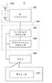
- FIG. 13 is a block diagram illustrating a configuration example of UE2.
- Radio-frequency (RF) transceiver 1301 performs analog RF signal processing to communicate with gNB1.
- the RF transceiver 1301 may include multiple transceivers.
- Analog RF signal processing performed by the RF transceiver 1301 includes frequency up-conversion, frequency down-conversion, and amplification.
- RF transceiver 1301 is coupled to antenna array 1302 and baseband processor 1303.
- the RF transceiver 1301 receives modulation symbol data (or OFDM symbol data) from the baseband processor 1303, generates a transmission RF signal, and supplies the transmission RF signal to the antenna array 1302.
- the RF transceiver 1301 generates a baseband received signal based on the received RF signal received by the antenna array 1302 and supplies this to the baseband processor 1303.
- the RF transceiver 1301 may include an analog beamformer circuit for beamforming.
- the analog beamformer circuit includes, for example, a plurality of phase shifters and a plurality of power amplifiers.
- the baseband processor 1303 performs digital baseband signal processing (data plane processing) and control plane processing for wireless communication.
- Digital baseband signal processing consists of (a) data compression / decompression, (b) data segmentation / concatenation, (c) ⁇ transmission format (transmission frame) generation / decomposition, and (d) transmission path encoding / decoding. , (E) modulation (symbol mapping) / demodulation, and (f) generation of OFDM symbol data (baseband OFDM signal) by Inverse Fast Fourier Transform (IFFT).
- control plane processing includes layer 1 (eg, transmission power control), layer 2 (eg, radio resource management, hybrid automatic repeat request (HARQ) processing), and layer 3 (eg, attach, mobility, and call management). Communication management).
- the digital baseband signal processing by the baseband processor 1303 may include signal processing of the Packet Data Convergence Protocol (PDCP) layer, Radio Link Control (RLC) layer, MAC layer, and PHY layer.
- the control plane processing by the baseband processor 1303 may include Non-Access-Stratum (NAS) protocol, RRC protocol, and MAC CE processing.
- PDCP Packet Data Convergence Protocol
- RLC Radio Link Control
- MAC Medium Access-Stratum
- MAC CE Non-Access-Stratum
- the baseband processor 1303 may perform MIMO encoding and precoding for beamforming.
- the baseband processor 1303 may include a modem processor (e.g., DSP) that performs digital baseband signal processing and a protocol stack processor (e.g., CPU or MPU) that performs control plane processing.
- a protocol stack processor e.g., CPU or MPU
- a protocol stack processor that performs control plane processing may be shared with an application processor 1304 described later.
- the application processor 1304 is also called a CPU, MPU, microprocessor, or processor core.
- the application processor 1304 may include a plurality of processors (a plurality of processor cores).
- the application processor 1304 is a system software program (Operating System (OS)) read from the memory 1306 or a memory (not shown) and various application programs (for example, call application, web browser, mailer, camera operation application, music playback)
- OS Operating System
- application programs for example, call application, web browser, mailer, camera operation application, music playback
- Various functions of UE2 are realized by executing (application).
- the baseband processor 1303 and the application processor 1304 may be integrated on a single chip, as indicated by the dashed line (1305) in FIG.
- the baseband processor 1303 and the application processor 1304 may be implemented as one System on Chip (SoC) device 1305.
- SoC System on Chip
- An SoC device is sometimes called a system Large Scale Integration (LSI) or chipset.
- the memory 1306 is a volatile memory, a nonvolatile memory, or a combination thereof.
- the memory 1306 may include a plurality of physically independent memory devices.
- the volatile memory is, for example, SRAM or DRAM or a combination thereof.
- the non-volatile memory is MROM, EEPROM, flash memory, or hard disk drive, or any combination thereof.
- the memory 1306 may include an external memory device accessible from the baseband processor 1303, the application processor 1304, and the SoC 1305.
- the memory 1306 may include an embedded memory device integrated within the baseband processor 1303, the application processor 1304, or the SoC 1305.
- the memory 1306 may include a memory in a Universal Integrated Circuit Card (UICC).
- UICC Universal Integrated Circuit Card
- the memory 1306 may store one or more software modules (computer programs) 1307 including an instruction group and data for performing processing by the UE 2 described in the plurality of embodiments.
- the baseband processor 1303 or the application processor 1304 is configured to read the software module 1307 from the memory 1306 and execute the software module 1307 to perform the processing of the UE 2 described with reference to the drawings in the above-described embodiment. May be.
- each of the processors included in the gNB 1, UE 2, and eNB 5 includes a group of instructions for causing a computer to execute the algorithm described with reference to the drawings.
- One or more programs are executed.
- the program can be stored and supplied to a computer using various types of non-transitory computer readable media.
- Non-transitory computer readable media include various types of tangible storage media (tangible storage medium).
- non-transitory computer-readable media are magnetic recording media (eg flexible disks, magnetic tapes, hard disk drives), magneto-optical recording media (eg magneto-optical discs), Compact Disc Read Only Memory (CD-ROM), CD-ROM R, CD-R / W, semiconductor memory (for example, mask ROM, Programmable ROM (PROM), Erasable PROM (EPROM), flash ROM, Random Access Memory (RAM)).
- the program may also be supplied to the computer by various types of temporary computer-readable media. Examples of transitory computer readable media include electrical signals, optical signals, and electromagnetic waves.
- the temporary computer-readable medium can supply the program to the computer via a wired communication path such as an electric wire and an optical fiber, or a wireless communication path.
- the 5G-RAN3 and E-UTRAN6 described in the above embodiment may be implemented based on the Cloud Radio Access Network (C-RAN) concept.
- C-RAN is sometimes referred to as Centralized RAN. Therefore, the processing and operation performed by each of gNB1 and eNB5 described in the above embodiment are provided by a Digital Unit (DU) included in the C-RAN architecture or by a combination of DU and Radio Unit (RU). May be.
- DU is called Baseband Unit (BBU) or Central Unit (CU).
- RU is also called Remote Radio Head (RRH), Remote Radio Equipment (RRE), Distributed Unit (DU), or Transmission and Reception Point (TRP or TRxP). That is, the process and operation performed by each of the gNB 1 and the eNB 5 described in the above embodiment may be provided by any one or a plurality of radio stations (or RAN nodes).
- UE2 was further set (or authorized) to UE2 by the network (ie, 5G-CN4 or 5G-RAN3 or both) when UE2 was in the RRC_CONNECTED state.
- the network ie, 5G-CN4 or 5G-RAN3 or both
- it may be configured to change the RRC state transition behavior of UE 2 depending on one or more network slices that have been accepted. For example, if UE2 has set, allowed, or approved a predetermined network slice (or slice category or slice type (eg, Slice / Service Type: ⁇ SST)), it moves from the NR RRC_INACTIVE state to the E-UTRA RRC_CONNECTED state. Otherwise, the state transition from the NR RRC_INACTIVE state to the E-UTRA RRC_IDLE state may be executed.
- state transition from NR ⁇ ⁇ ⁇ ⁇ RRC_INACTIVE state to E-UTRA RRC_CONNECTED state is permitted for at least one of those network slices If so, the state transition may be performed. Instead, UE2 performs the state transition when the state transition from the NR RRC_INACTIVE state to the E-UTRA RRC_CONNECTED state is permitted for all the network slices that have been set, permitted, or approved. It may be.
- the UE 2 executes a procedure for resuming a radio data bearer (DRB) corresponding to a network slice in which state transition from the NR RRC_INACTIVE state to the E-UTRA RRC_CONNECTED state is permitted. Further, the UE 2 may release (or discard) the radio data bearer configuration (e.g., “radio bearer configuration”) corresponding to the other network slice that has been set. At this time, the AS layer of UE2 may notify the recovered and released (or discarded) radio data bearer information to the NAS layer of UE2. In response to the notification, the NAS layer of UE2 may execute a procedure necessary for inter-RAT ⁇ mobility.
- DRB radio data bearer
- the system information transmitted from the eNB 5 in the target E-UTRA cell 51 after cell reselection may include the information. That is, based on the information transmitted in the target E-UTRA cell 51 for cell reselection, the UE 2 is permitted to make a state transition from the NR RRC_INACTIVE state to the E-UTRA RRC_CONNECTED state in the E-UTRA cell 51. It may be determined.
- a wireless terminal At least one transceiver; One or more cells of a first radio access network (RAN) that supports a first radio access technology (RAT) and has an interface with a first core network (CN), and a second RAT.
- At least one processor configured to control the at least one transceiver in one or more cells of a second RAN; With The at least one processor is configured to control state transition of the wireless terminal between an RRC_CONNECTED state of the first RAT, an RRC_INACTIVE state of the first RAT, and an RRC_IDLE state of the first RAT.
- the at least one processor is configured to control a state transition of the wireless terminal between an RRC_CONNECTED state of the second RAT and an RRC_IDLE state of the second RAT;
- the at least one processor is in the RRC_INACTIVE state of the first RAT in the first RAN and has a Non-Access Stratum (NAS) connection with the first CN.
- NAS Non-Access Stratum
- the at least one processor may move the wireless terminal from the RRC_INACTIVE state of the first RAT if the second RAN supports interworking with at least one of the first CN and the first RAN. Configured to transition to the RRC_CONNECTED state of the second RAT, The wireless terminal according to attachment 1.
- the RRC_CONNECTED state of the second RAT includes a first sub-state in which a complete RRC connection is maintained, and a second RRC connection that is lighter than the complete RRC connection in order to reduce signaling.
- the at least one processor is configured to transition the wireless terminal from the RRC_INACTIVE state of the first RAT to the second sub-state within the RRC_CONNECTED state of the second RAT.
- the wireless terminal according to attachment 2.
- the at least one processor may move the wireless terminal from the RRC_INACTIVE state of the first RAT if the second RAN supports interworking with both the first CN and the first RAN. Transition to the RRC_CONNECTED state of the first RAT, and then the wireless terminal is transitioned from the RRC_CONNECTED state of the first RAT to the RRC_CONNECTED state of the second RAT.
- the wireless terminal according to attachment 1.
- the at least one processor may move the wireless terminal out of the RRC_INACTIVE state of the first RAT if the second RAN does not support interworking with either the first CN or the first RAN. Configured to transition to the RRC_IDLE state of the second RAT, The wireless terminal according to any one of appendices 1 to 4.
- the at least one processor is configured to perform a location update procedure to a second CN via a second RAN after transitioning the wireless terminal to the RRC_IDLE state of the second RAT.
- the wireless terminal according to attachment 5.
- the RRC_CONNECTED state of the first RAT is a state in which the wireless terminal and the first RAN maintain a first access layer (Access stratum (AS)) context related to the first RAT, and the wireless terminal Is known by the first RAN at the cell level
- the RRC_INACTIVE state of the first RAT is a state in which the wireless terminal and the first RAN maintain at least a part of the first AS context, and the position of the wireless terminal is determined by the first RAN.
- the RRC_IDLE state of the first RAT is a state in which the wireless terminal and the first RAN release the first AS context, and the position of the wireless terminal is known by the first RAN. Is not in the state
- the RRC_CONNECTED state of the second RAT is a state in which the wireless terminal and the second RAN maintain a second AS context related to the second RAT, and the position of the wireless terminal is at the cell level.
- a state known by the second RAN, The RRC_IDLE state of the second RAT is a state in which the wireless terminal and the second RAN release the second AS context, and the position of the wireless terminal is known by the second RAN. Is not in a state, The wireless terminal according to any one of appendices 1 to 6.
- the RAN notification area may not report the cell reselection to the first RAN even if the wireless terminal moves between cells by cell reselection when the wireless terminal is in the RRC_INACTIVE state of the first RAT.
- Area The wireless terminal according to appendix 7.
- the first RAT is a 5G RAT;
- the second RAT is an LTE RAT.
- the wireless terminal according to any one of appendices 1 to 8.
- the specific RRC state transition includes a state transition of the wireless terminal from the RRC_INACTIVE state of the first RAT to the RRC_CONNECTED state of the second RAT. base station.
- the information element is a Non-Access Stratum (NAS) information element included in the system information.
- NAS Non-Access Stratum
- the information element includes at least one of a first radio access network (RAN) associated with the first RAT and a first core network (CN) associated with the first RAT. Indicates whether to support interworking The base station according to any one of appendices 10 to 12.
- RAN radio access network
- CN core network
- RAN radio access network
- RAT radio access technology
- CN core network
- a method in a wireless terminal configured to operate in a plurality of RAN cells comprising: Controlling the state transition of the wireless terminal between the RRC_CONNECTED state of the first RAT, the RRC_INACTIVE state of the first RAT, and the RRC_IDLE state of the first RAT; Controlling the state transition of the wireless terminal between the RRC_CONNECTED state of the second RAT and the RRC_IDLE state of the second RAT, and the RRC_INACTIVE of the first RAT in the first RAN.
- a method comprising:
- a method in a base station supporting a second Radio Access Technology (RAT) comprising: Comprising transmitting an information element in a cell of the base station for a wireless terminal to determine whether or not the base station supports a specific RRC state transition,
- the specific RRC state transition includes a state transition of the wireless terminal from the RRC_INACTIVE state of the first RAT to the RRC_CONNECTED state of the second RAT.
- RAN radio access network
- RAT radio access technology
- CN core network
- the second RAN Changing the RRC state transition operation of the wireless terminal depending on whether interworking with at least one of the first CN and the first RAN is supported; Comprising program.
- NAS Non-Access Stratum
- the specific RRC state transition includes a state transition of the wireless terminal from the RRC_INACTIVE state of the first RAT to the RRC_CONNECTED state of the second RAT. program.
- gNodeB 2 User Equipment (UE) 3 5G Radio Access Network (5G-RAN) 4 5G Core Network (5G-CN) 5 eNodeB (eNB) 6 Evolved Universal Terrestrial Radio Access Network (E-UTRAN) 7 Evolved Packet Core (EPC) 11 cell 1201 RF transceiver 1204 processor 1205 memory 1301 RF transceiver 1303 baseband processor 1304 application processor 1306 memory
Landscapes
- Engineering & Computer Science (AREA)
- Computer Networks & Wireless Communication (AREA)
- Signal Processing (AREA)
- Mobile Radio Communication Systems (AREA)
Abstract
Dans les cas où un terminal sans fil (2) se trouve dans un état RRC_INACTIVE de première RAT dans un premier réseau d'accès radio (RAN) (3) et que le terminal sans fil (2) se déplace vers une cellule (51) dans un second RAN (6) lorsqu'il possède une connexion strate de non-accès (NAS) avec un premier réseau central (CN) (4) associé à une première RAT, le terminal sans fil (2) change une opération de transition d'état RRC du terminal sans fil (2) en fonction du fait que le second RAN (6) prend en charge l'interfonctionnement avec le premier CN (4) et/ou le premier RAN (3).
Priority Applications (4)
| Application Number | Priority Date | Filing Date | Title |
|---|---|---|---|
| US16/473,299 US11109286B2 (en) | 2017-01-05 | 2017-11-21 | Radio terminal, base station, and methods and non-transitory computer-readable media therefor |
| JP2018560331A JP6769494B2 (ja) | 2017-01-05 | 2017-11-21 | 無線端末及び基地局並びにこれらの方法 |
| EP17890706.9A EP3567979B1 (fr) | 2017-01-05 | 2017-11-21 | Terminal sans fil, station de base, procédés associés et support lisible par ordinateur non temporaire |
| US17/374,031 US11736991B2 (en) | 2017-01-05 | 2021-07-13 | Radio terminal, base station, and methods and non-transitory computer-readable media therefor |
Applications Claiming Priority (2)
| Application Number | Priority Date | Filing Date | Title |
|---|---|---|---|
| JP2017000802 | 2017-01-05 | ||
| JP2017-000802 | 2017-01-05 |
Related Child Applications (2)
| Application Number | Title | Priority Date | Filing Date |
|---|---|---|---|
| US16/473,299 A-371-Of-International US11109286B2 (en) | 2017-01-05 | 2017-11-21 | Radio terminal, base station, and methods and non-transitory computer-readable media therefor |
| US17/374,031 Continuation US11736991B2 (en) | 2017-01-05 | 2021-07-13 | Radio terminal, base station, and methods and non-transitory computer-readable media therefor |
Publications (1)
| Publication Number | Publication Date |
|---|---|
| WO2018128018A1 true WO2018128018A1 (fr) | 2018-07-12 |
Family
ID=62791072
Family Applications (1)
| Application Number | Title | Priority Date | Filing Date |
|---|---|---|---|
| PCT/JP2017/041820 WO2018128018A1 (fr) | 2017-01-05 | 2017-11-21 | Terminal sans fil, station de base, procédés associés et support lisible par ordinateur non temporaire |
Country Status (4)
| Country | Link |
|---|---|
| US (2) | US11109286B2 (fr) |
| EP (1) | EP3567979B1 (fr) |
| JP (3) | JP6769494B2 (fr) |
| WO (1) | WO2018128018A1 (fr) |
Cited By (3)
| Publication number | Priority date | Publication date | Assignee | Title |
|---|---|---|---|---|
| WO2020033780A1 (fr) * | 2018-08-08 | 2020-02-13 | Google Llc | Sélection de réseau mobile terrestre public par un équipement utilisateur dans un mode inactif au niveau d'une couche de commande de ressources radio |
| JP2020048100A (ja) * | 2018-09-20 | 2020-03-26 | Kddi株式会社 | 待ち受け状態で通信を行う端末装置、その制御方法、及びプログラム |
| JP2020065209A (ja) * | 2018-10-18 | 2020-04-23 | キヤノン株式会社 | 通信装置、制御方法、および、プログラム |
Families Citing this family (29)
| Publication number | Priority date | Publication date | Assignee | Title |
|---|---|---|---|---|
| BR112018015340B1 (pt) * | 2016-01-27 | 2024-01-02 | Huawei Technologies Co., Ltd | Método de comunicação e aparelho de comunicações |
| JP6769494B2 (ja) * | 2017-01-05 | 2020-10-14 | 日本電気株式会社 | 無線端末及び基地局並びにこれらの方法 |
| KR102571341B1 (ko) | 2017-02-03 | 2023-08-29 | 주식회사 아이티엘 | 무선 통신 시스템에서 단말의 이동성을 지원하는 네트워크 및 단말의 동작 방법 및 장치 |
| PL3583809T3 (pl) * | 2017-02-12 | 2022-07-18 | FG Innovation Company Limited | Zarządzanie mobilnością urządzenia użytkownika rrc inactive |
| US10764785B2 (en) * | 2017-03-07 | 2020-09-01 | Htc Corporation | Device and method of handling network slice information |
| KR102285451B1 (ko) * | 2017-03-21 | 2021-08-03 | 삼성전자 주식회사 | 이동통신에서 연결 모드의 비연속 수신 모드를 지원하는 방법 및 장치 |
| KR102222830B1 (ko) * | 2017-03-21 | 2021-03-04 | 삼성전자 주식회사 | 이동통신에서 연결 모드의 비연속 수신 모드를 지원하는 방법 및 장치 |
| EP3596971B1 (fr) | 2017-05-05 | 2021-10-13 | Sony Group Corporation | Réseau de communication mobile, dispositif de communication, équipement d'infrastructure et procédés |
| US10581495B2 (en) * | 2017-08-18 | 2020-03-03 | Nokia Technologies Oy | Physical layer configuration continuity during radio resource control restoration |
| EP3689096B1 (fr) * | 2017-09-28 | 2022-03-30 | Telefonaktiebolaget LM Ericsson (PUBL) | Procédés et dispositifs pour la préservation d'un pdcp nr lors d'une reprise/suspension de rrc |
| CN109756891A (zh) * | 2017-11-08 | 2019-05-14 | 夏普株式会社 | 数据传输方法、设备和存储介质 |
| JP2021514554A (ja) * | 2017-12-21 | 2021-06-10 | オッポ広東移動通信有限公司Guangdong Oppo Mobile Telecommunications Corp., Ltd. | エリア優先順位を決定する方法、ネットワーク装置、及びコンピュータ記憶媒体 |
| US10849177B2 (en) * | 2018-01-08 | 2020-11-24 | Htc Corporation | Method of handling radio access technology indication and related communication device |
| US11252628B2 (en) * | 2018-01-09 | 2022-02-15 | Htc Corporation | Device and method for handling new radio capabilities |
| KR102402844B1 (ko) * | 2018-01-10 | 2022-05-27 | 삼성전자주식회사 | 무선 통신 시스템에서 단말의 상태를 관리하기 위한 장치 및 방법 |
| CN110225600B (zh) * | 2018-03-01 | 2021-09-07 | 华为技术有限公司 | 通信方法及装置 |
| WO2019194733A1 (fr) * | 2018-04-05 | 2019-10-10 | Telefonaktiebolaget Lm Ericsson (Publ) | Adaptation de taille d'identifiant de reprise dans une zone de notification composée de multiples technologies d'accès radio |
| ES2947134T3 (es) * | 2018-05-07 | 2023-08-02 | Ericsson Telefon Ab L M | Métodos para suspender la inactividad en reanudaciones y reanudar la inactividad en suspensiones |
| US11419022B2 (en) * | 2018-05-11 | 2022-08-16 | FG Innovation Company Limited | Cell prioritization for cell (re)selection in wireless communication systems |
| EP3858088B1 (fr) * | 2018-09-25 | 2022-03-09 | Telefonaktiebolaget Lm Ericsson (Publ) | Noeud de réseau radio, dispositif sans fil et procédés associés pour la reprise d'une connexion radio |
| WO2020067959A1 (fr) | 2018-09-25 | 2020-04-02 | Telefonaktiebolaget Lm Ericsson (Publ) | Nœud de réseau radio, dispositif sans fil et procédés associés de rétablissement d'une connexion radio |
| EP3837921A1 (fr) * | 2018-10-05 | 2021-06-23 | Nokia Technologies Oy | Procédé, appareil et programme informatique |
| US20210345208A1 (en) * | 2018-10-25 | 2021-11-04 | Telefonaktiebolaget Lm Ericsson (Publ) | Methods and nodes for performing a handover at resume |
| US11357063B2 (en) * | 2019-09-14 | 2022-06-07 | Commscope Technologies Llc | Physical cell identifier collision detection |
| CN113179512B (zh) * | 2020-07-30 | 2022-09-09 | 华为技术有限公司 | 一种通信方法及通信装置 |
| US11490314B2 (en) * | 2020-09-10 | 2022-11-01 | T-Mobile Usa, Inc. | Handover optimization during 5G to 4G mobility |
| EP4234742A1 (fr) | 2021-01-12 | 2023-08-30 | Nippon Steel Corporation | Tôle d'acier laminée à chaud |
| CN115942408A (zh) * | 2021-08-04 | 2023-04-07 | 中兴通讯股份有限公司 | 通信方法、设备和存储介质 |
| WO2023041165A1 (fr) * | 2021-09-16 | 2023-03-23 | Nokia Technologies Oy | Appareil comprenant au moins un processeur |
Citations (1)
| Publication number | Priority date | Publication date | Assignee | Title |
|---|---|---|---|---|
| JP2017000802A (ja) | 2016-08-26 | 2017-01-05 | 日機装株式会社 | しごき型ポンプ |
Family Cites Families (1)
| Publication number | Priority date | Publication date | Assignee | Title |
|---|---|---|---|---|
| JP6769494B2 (ja) | 2017-01-05 | 2020-10-14 | 日本電気株式会社 | 無線端末及び基地局並びにこれらの方法 |
-
2017
- 2017-11-21 JP JP2018560331A patent/JP6769494B2/ja active Active
- 2017-11-21 WO PCT/JP2017/041820 patent/WO2018128018A1/fr unknown
- 2017-11-21 EP EP17890706.9A patent/EP3567979B1/fr active Active
- 2017-11-21 US US16/473,299 patent/US11109286B2/en active Active
-
2020
- 2020-09-18 JP JP2020156894A patent/JP7004046B2/ja active Active
-
2021
- 2021-07-13 US US17/374,031 patent/US11736991B2/en active Active
- 2021-12-28 JP JP2021213668A patent/JP7279773B2/ja active Active
Patent Citations (1)
| Publication number | Priority date | Publication date | Assignee | Title |
|---|---|---|---|---|
| JP2017000802A (ja) | 2016-08-26 | 2017-01-05 | 日機装株式会社 | しごき型ポンプ |
Non-Patent Citations (7)
| Title |
|---|
| "3GPP TSG-RAN WG2 Meeting #96, Reno, USA", 14 November 2016, NTT DOCOMO, INC., article "UE state transition diagram for NR" |
| "3rd Generation Partnership Project; Technical Specification Group Services and System Aspects; Study on Architecture for Next Generation System (Release 14", 3GPP TR 23.799 V14.0.0, December 2016 (2016-12-01) |
| ETSI MCC: "Skeleton report", 3GPP TSG-RAN WG2 #96 RAN2-96-RENO-CHAIRMAN-NOTES, 18 November 2016 (2016-11-18), pages 95 - 96, XP051193732, Retrieved from the Internet <URL:https://www.3gpp.org/ftp/tsg_ran/WG2_RL2/TSGR2_96/Docs/Report/Hisory/RAN2-96-Reno-chairman-Note-18_2016-eom.doc> * |
| INTEL CORPORATION: "LTE and NR interaction for configuration coordination", 3GPP TSG-RAN WG2 #96 R2-168507, no. R2-168507, 5 November 2016 (2016-11-05), Reno, USA, XP051193060 * |
| NTT DOCOMO; INC: "UE state transition diagram for NR", 3GPP TSG-RAN WG2 #96 R2-168077, no. R2-168077, 5 November 2016 (2016-11-05), XP051192943 * |
| SAMSUNG: "Overview of the NR RRC state machine and modelling of the INACTIVE state", 3GPP TSG-RAN WG2 #96, no. R2-167493, 5 November 2016 (2016-11-05), Reno, USA, XP051192777 * |
| ZTE; ZTE MICROELECTRONICS: "Further consideration on the new RAN controlled state in NR", 3GPP TSG-RAN WG2 #96BIS R2-166611, no. R2-166611, 30 September 2016 (2016-09-30), XP051161794 * |
Cited By (10)
| Publication number | Priority date | Publication date | Assignee | Title |
|---|---|---|---|---|
| WO2020033780A1 (fr) * | 2018-08-08 | 2020-02-13 | Google Llc | Sélection de réseau mobile terrestre public par un équipement utilisateur dans un mode inactif au niveau d'une couche de commande de ressources radio |
| CN112534957A (zh) * | 2018-08-08 | 2021-03-19 | 谷歌有限责任公司 | 处于无线电资源控制层处的不活动模式中的用户设备的公共陆地移动网络选择 |
| US11496958B2 (en) | 2018-08-08 | 2022-11-08 | Google Llc | Public land mobile network selection by user equipment in an inactive mode at a radio resource control layer |
| CN112534957B (zh) * | 2018-08-08 | 2024-04-12 | 谷歌有限责任公司 | 处于无线电资源控制层处的不活动模式中的用户设备的公共陆地移动网络选择 |
| JP2020048100A (ja) * | 2018-09-20 | 2020-03-26 | Kddi株式会社 | 待ち受け状態で通信を行う端末装置、その制御方法、及びプログラム |
| WO2020059314A1 (fr) * | 2018-09-20 | 2020-03-26 | Kddi株式会社 | Dispositif terminal qui réalise une communication dans un état de veille, son procédé de commande, et programme |
| CN112673706A (zh) * | 2018-09-20 | 2021-04-16 | 凯迪迪爱通信技术有限公司 | 以待机状态进行通信的终端设备及其控制方法、程序 |
| US20210204184A1 (en) * | 2018-09-20 | 2021-07-01 | Kddi Corporation | Terminal device that performs communication in stand-by state, method for controlling the same, and computer-readable storage medium |
| JP2020065209A (ja) * | 2018-10-18 | 2020-04-23 | キヤノン株式会社 | 通信装置、制御方法、および、プログラム |
| JP7210220B2 (ja) | 2018-10-18 | 2023-01-23 | キヤノン株式会社 | 通信装置、制御方法、および、プログラム |
Also Published As
| Publication number | Publication date |
|---|---|
| JP7004046B2 (ja) | 2022-01-21 |
| JP6769494B2 (ja) | 2020-10-14 |
| EP3567979A4 (fr) | 2019-11-20 |
| US20210345194A1 (en) | 2021-11-04 |
| JP2022043257A (ja) | 2022-03-15 |
| EP3567979B1 (fr) | 2021-10-13 |
| US20190342804A1 (en) | 2019-11-07 |
| EP3567979A1 (fr) | 2019-11-13 |
| JPWO2018128018A1 (ja) | 2019-11-07 |
| JP2021002859A (ja) | 2021-01-07 |
| JP7279773B2 (ja) | 2023-05-23 |
| US11736991B2 (en) | 2023-08-22 |
| US11109286B2 (en) | 2021-08-31 |
Similar Documents
| Publication | Publication Date | Title |
|---|---|---|
| JP7004046B2 (ja) | 無線端末及び基地局並びにこれらの方法 | |
| JP7063404B2 (ja) | gNB及びUE | |
| JP7290193B2 (ja) | 無線端末及び無線端末における方法 | |
| WO2018128017A1 (fr) | Noeud de réseau d'accès sans fil, terminal sans fil, noeud de réseau central, procédés associés et support lisible par ordinateur non temporaire | |
| WO2017017890A1 (fr) | Terminal sans fil, station de base et procédé correspondant |
Legal Events
| Date | Code | Title | Description |
|---|---|---|---|
| 121 | Ep: the epo has been informed by wipo that ep was designated in this application |
Ref document number: 17890706 Country of ref document: EP Kind code of ref document: A1 |
|
| ENP | Entry into the national phase |
Ref document number: 2018560331 Country of ref document: JP Kind code of ref document: A |
|
| NENP | Non-entry into the national phase |
Ref country code: DE |
|
| ENP | Entry into the national phase |
Ref document number: 2017890706 Country of ref document: EP Effective date: 20190805 |