WO2018124773A1 - 축류팬 - Google Patents
축류팬 Download PDFInfo
- Publication number
- WO2018124773A1 WO2018124773A1 PCT/KR2017/015644 KR2017015644W WO2018124773A1 WO 2018124773 A1 WO2018124773 A1 WO 2018124773A1 KR 2017015644 W KR2017015644 W KR 2017015644W WO 2018124773 A1 WO2018124773 A1 WO 2018124773A1
- Authority
- WO
- WIPO (PCT)
- Prior art keywords
- fan
- trailing edge
- longitudinal direction
- axial
- axial flow
- Prior art date
- Legal status (The legal status is an assumption and is not a legal conclusion. Google has not performed a legal analysis and makes no representation as to the accuracy of the status listed.)
- Ceased
Links
Images



Classifications
-
- F—MECHANICAL ENGINEERING; LIGHTING; HEATING; WEAPONS; BLASTING
- F04—POSITIVE - DISPLACEMENT MACHINES FOR LIQUIDS; PUMPS FOR LIQUIDS OR ELASTIC FLUIDS
- F04D—NON-POSITIVE-DISPLACEMENT PUMPS
- F04D29/00—Details, component parts, or accessories
- F04D29/66—Combating cavitation, whirls, noise, vibration or the like; Balancing
- F04D29/661—Combating cavitation, whirls, noise, vibration or the like; Balancing especially adapted for elastic fluid pumps
- F04D29/666—Combating cavitation, whirls, noise, vibration or the like; Balancing especially adapted for elastic fluid pumps by means of rotor construction or layout, e.g. unequal distribution of blades or vanes
-
- F—MECHANICAL ENGINEERING; LIGHTING; HEATING; WEAPONS; BLASTING
- F04—POSITIVE - DISPLACEMENT MACHINES FOR LIQUIDS; PUMPS FOR LIQUIDS OR ELASTIC FLUIDS
- F04D—NON-POSITIVE-DISPLACEMENT PUMPS
- F04D29/00—Details, component parts, or accessories
- F04D29/26—Rotors specially for elastic fluids
- F04D29/32—Rotors specially for elastic fluids for axial flow pumps
- F04D29/38—Blades
- F04D29/384—Blades characterised by form
-
- F—MECHANICAL ENGINEERING; LIGHTING; HEATING; WEAPONS; BLASTING
- F04—POSITIVE - DISPLACEMENT MACHINES FOR LIQUIDS; PUMPS FOR LIQUIDS OR ELASTIC FLUIDS
- F04D—NON-POSITIVE-DISPLACEMENT PUMPS
- F04D19/00—Axial-flow pumps
-
- F—MECHANICAL ENGINEERING; LIGHTING; HEATING; WEAPONS; BLASTING
- F04—POSITIVE - DISPLACEMENT MACHINES FOR LIQUIDS; PUMPS FOR LIQUIDS OR ELASTIC FLUIDS
- F04D—NON-POSITIVE-DISPLACEMENT PUMPS
- F04D19/00—Axial-flow pumps
- F04D19/002—Axial flow fans
-
- F—MECHANICAL ENGINEERING; LIGHTING; HEATING; WEAPONS; BLASTING
- F04—POSITIVE - DISPLACEMENT MACHINES FOR LIQUIDS; PUMPS FOR LIQUIDS OR ELASTIC FLUIDS
- F04D—NON-POSITIVE-DISPLACEMENT PUMPS
- F04D29/00—Details, component parts, or accessories
- F04D29/26—Rotors specially for elastic fluids
- F04D29/32—Rotors specially for elastic fluids for axial flow pumps
- F04D29/38—Blades
-
- F—MECHANICAL ENGINEERING; LIGHTING; HEATING; WEAPONS; BLASTING
- F04—POSITIVE - DISPLACEMENT MACHINES FOR LIQUIDS; PUMPS FOR LIQUIDS OR ELASTIC FLUIDS
- F04D—NON-POSITIVE-DISPLACEMENT PUMPS
- F04D29/00—Details, component parts, or accessories
- F04D29/26—Rotors specially for elastic fluids
- F04D29/32—Rotors specially for elastic fluids for axial flow pumps
- F04D29/38—Blades
- F04D29/384—Blades characterised by form
- F04D29/386—Skewed blades
-
- F—MECHANICAL ENGINEERING; LIGHTING; HEATING; WEAPONS; BLASTING
- F04—POSITIVE - DISPLACEMENT MACHINES FOR LIQUIDS; PUMPS FOR LIQUIDS OR ELASTIC FLUIDS
- F04D—NON-POSITIVE-DISPLACEMENT PUMPS
- F04D29/00—Details, component parts, or accessories
- F04D29/66—Combating cavitation, whirls, noise, vibration or the like; Balancing
-
- F—MECHANICAL ENGINEERING; LIGHTING; HEATING; WEAPONS; BLASTING
- F04—POSITIVE - DISPLACEMENT MACHINES FOR LIQUIDS; PUMPS FOR LIQUIDS OR ELASTIC FLUIDS
- F04D—NON-POSITIVE-DISPLACEMENT PUMPS
- F04D29/00—Details, component parts, or accessories
- F04D29/66—Combating cavitation, whirls, noise, vibration or the like; Balancing
- F04D29/661—Combating cavitation, whirls, noise, vibration or the like; Balancing especially adapted for elastic fluid pumps
- F04D29/667—Combating cavitation, whirls, noise, vibration or the like; Balancing especially adapted for elastic fluid pumps by influencing the flow pattern, e.g. suppression of turbulence
-
- F—MECHANICAL ENGINEERING; LIGHTING; HEATING; WEAPONS; BLASTING
- F05—INDEXING SCHEMES RELATING TO ENGINES OR PUMPS IN VARIOUS SUBCLASSES OF CLASSES F01-F04
- F05D—INDEXING SCHEME FOR ASPECTS RELATING TO NON-POSITIVE-DISPLACEMENT MACHINES OR ENGINES, GAS-TURBINES OR JET-PROPULSION PLANTS
- F05D2240/00—Components
- F05D2240/20—Rotors
- F05D2240/30—Characteristics of rotor blades, i.e. of any element transforming dynamic fluid energy to or from rotational energy and being attached to a rotor
- F05D2240/303—Characteristics of rotor blades, i.e. of any element transforming dynamic fluid energy to or from rotational energy and being attached to a rotor related to the leading edge of a rotor blade
-
- F—MECHANICAL ENGINEERING; LIGHTING; HEATING; WEAPONS; BLASTING
- F05—INDEXING SCHEMES RELATING TO ENGINES OR PUMPS IN VARIOUS SUBCLASSES OF CLASSES F01-F04
- F05D—INDEXING SCHEME FOR ASPECTS RELATING TO NON-POSITIVE-DISPLACEMENT MACHINES OR ENGINES, GAS-TURBINES OR JET-PROPULSION PLANTS
- F05D2240/00—Components
- F05D2240/20—Rotors
- F05D2240/30—Characteristics of rotor blades, i.e. of any element transforming dynamic fluid energy to or from rotational energy and being attached to a rotor
- F05D2240/304—Characteristics of rotor blades, i.e. of any element transforming dynamic fluid energy to or from rotational energy and being attached to a rotor related to the trailing edge of a rotor blade
Definitions
- the present invention relates to an axial flow fan, and more particularly, to an axial flow fan including a hub and a plurality of blades radially disposed on the circumference of the hub to which the blade root is coupled to the hub, wherein the blade has a trailing edge position.
- the axial fan is formed to have a waveform form in which the retreat and the regression are progressively repeated from the leading edge, and the trailing edge is located on the same plane, and the installation angle changes as the longitudinal direction of the wing changes.
- the axial fan is generally accommodated in the fan shroud, and a motor or the like for rotating the axial fan is fixed to the fan shroud, and the fan shroud is mounted to fix its position.
- the axial fan assembly formed by the axial fan, fan shroud, motor, etc. is mounted on the heat exchanger or the engine room floor and placed in front of or behind the heat exchanger.
- FIG. 1 illustrates one embodiment of the arrangement of a heat exchanger and axial fan assembly.
- the axial flow fan 10 is arranged in parallel with the heat exchangers 20 such as the radiator 21 and the condenser 22 with respect to the air blowing direction, thereby causing forced convection of air.
- the flow of air to the core of the heat exchanger 20 is made smoothly.
- FIG. 2 is a view showing a conventional axial flow fan.
- the axial fan 10 includes a hub 12 and a plurality of vanes 11 radially disposed on the circumference of the hub 12.
- a fan band 13 may be further provided at the tip 11a of the wing 11 to connect the plurality of wings 11 to each other.
- the axial flow fan 10 is for causing forced blowing to smoothly flow the air passing through the heat exchanger, the shape design of the blade 11 for increasing the blowing efficiency is very important.
- an object of the present invention is to provide an axial fan comprising a hub, and a plurality of wings radially disposed on the circumference of the hub coupled to the hub;
- the present invention provides an axial fan capable of reducing the power consumption as well as reducing the noise generated by the operation of the axial fan by modifying the shape of the blade.
- the axial flow fan comprises a hub and a plurality of wings radially disposed on the circumference of the hub and the blade root is coupled to the hub, the radial direction of the axial flow fan is called a longitudinal direction,
- the length connecting the leading edge and the trailing edge of the blade is called chord length (L)
- the angle formed with the horizontal plane of the axial fan at the trailing edge of the blade is an installation angle ( ⁇ ).
- ⁇ installation angle
- the blade has a waveform form in which the position of the trailing edge is gradually retracted and moved forward from the leading edge as the wing progresses in the longitudinal direction, and the position and the installation angle of the trailing edge advance in the longitudinal direction. It is characterized by a constantly changing.
- the wing is characterized in that the chord length (L) is continuously changed as the longitudinal direction proceeds.
- the wing is characterized in that the position is continuously changed as the leading edge and the trailing edge proceeds in the longitudinal direction.
- the wing is characterized in that the wave shape of the trailing edge is formed so as to repeat at least two times as it proceeds in the longitudinal direction,
- the blade is characterized in that the trailing edge is formed by gradually retreating and advanced in the range of 6mm to 8mm from the leading edge.
- the blade is characterized in that the trailing edge is formed so as to be located on the same plane in the longitudinal direction from the hub.
- the axial flow fan is characterized in that it further comprises a fan band is formed in the shape of a circular ring connecting each tip of the wing.
- An axial flow fan is an axial flow fan including a hub and a plurality of wings radially disposed on the circumference of the hub coupled to the hub, the blade is retracted gradually from the leading edge and the position of the trailing edge and Advancing is formed to have a repetitive wave shape, the length of the chord and the installation angle is formed to change as it proceeds in the longitudinal direction of the wing, having a flow distribution having a different angle in the longitudinal direction of the outlet of the air passing through the trailing edge Accordingly, there is an advantage that the pressure distribution is dispersed and noise is reduced.
- the axial flow fan according to the present invention has a flow distribution having a different angle, so that the flow guide path from the leading edge to the trailing edge direction is formed, thereby minimizing the flow from the hub to the blade longitudinal direction, power consumption is reduced There is an advantage.
- FIG. 1 is a view showing the arrangement of a typical heat exchanger and axial fan.
- FIG. 2 is a view showing a general axial fan.
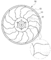
- FIG 3 is a view showing an axial flow fan according to the present invention.
- FIG. 4 is a view comparing the axial flow fan and the conventional axial flow fan according to the present invention.
- FIG. 5 is a view showing the analysis results of the axial flow fan according to the present invention.
- FIG. 6 is a view defining the chord length and installation angle of the axial flow fan according to the present invention.
- FIG. 7 is another view showing an axial fan according to the present invention.
- FIG. 8 is a view showing a fan band of the axial flow fan according to the present invention.
- FIG. 9 is a view showing the effect of the axial flow fan according to the present invention.
- FIG 3 is a view showing an axial flow fan according to the present invention
- Figure 4 is a view comparing the axial flow fan and the conventional axial flow fan according to the present invention.
- the axial flow fan 100 is formed including a hub 120 and the blade 110, chord length (L) (chord length) of the blade 110 ) And a setting angle ( ⁇ ) to specify the shape to reduce the noise without changing the configuration form of other shrouds, and can satisfy the airflow characteristics.
- the hub 120 is a portion forming a central region of the axial fan 100, and a rotation shaft is connected to the center of the axial fan 100.
- the hub 120 may be mounted with a fan motor for driving the axial flow fan (100).
- the wings 110 are arranged in a plurality of radially on the circumference of the hub 120, and transports air in the axial direction.
- the axial fan 100 may further include a fan band 130 is formed in the shape of a disc to connect the angular blade end of the wing (110).
- the structural safety of the entire axial fan 100 may be further increased.
- the radial direction of the axial fan 100 is defined as a longitudinal direction.
- the wing 110 has a leading edge 111 which is an area which is first contacted with air in the rotational direction, and a trailing edge 112 which is an area where air escapes to the side opposite to the leading edge 111. It includes.
- the above-mentioned length of the chord (L) means the length connecting the leading edge 111 and the trailing edge 112 of the blade 110 in a straight line
- the installation angle ( ⁇ ) is the axial flow fan 100 in the trailing edge 112 ) Means the horizontal plane and the forming angle. (See Figure 7)
- the blade 110 of the axial fan 100 has a waveform form in which the position of the trailing edge 112 is gradually retracted and moved forward from the leading edge 111 as the longitudinal direction progresses.
- the blade 110 has a waveform form in which the position of the trailing edge 112 in the longitudinal direction is gradually retracted and moved forward, and thus the position of the trailing edge 112 continuously changes as the longitudinal direction progresses.
- the installation angle ⁇ also changes continuously as it progresses in the longitudinal direction.
- the blade 100 of the axial flow fan according to the present invention can be continuously changed as the length of the chord length (L), for this purpose, the leading edge 111 and the trailing edge 112 continue to progress in the longitudinal direction
- the position may be changed shape.
- the length of the chord is uniformly formed when traveling in the longitudinal direction at the hub, whereas the axial fan 100 according to the present invention is positioned at the trailing edge 112 of the wing 110.
- the chord length (L) is formed in a shape that repeats that the longer and shorter with the retreat and advance of the trailing edge (112).
- the installation angle when the installation angle proceeds in the longitudinal direction, the installation angle is also formed smoothly in response to the slow change in the chord length.
- the blade 110 of the axial fan 100 has a wave shape different from the leading edge 111 to the chord length (L), according to the installation angle ( ⁇ ) also progresses in the longitudinal direction, It is formed to have a shape.
- the blade 110 of the axial fan 100 according to the present invention has different angles because the installation angle ( ⁇ ) of the trailing edge 112 through which air escapes from the blade 110 is formed differently in the longitudinal direction.
- the trailing edge 112 also distributes the flow of air at different angles.
- the pressure distribution is dispersed to reduce the noise.
- the blade 110 forms a plurality of air flow paths to reduce noise, and in the longitudinal direction to minimize the air flowing in the longitudinal direction from the hub 120, the waveform shape of the trailing edge 112 is It is preferable to form at least two or more repetitions, and of course, it is possible to set various repetitions according to the longitudinal direction.
- FIG. 5 is a view showing an analysis result of the axial flow fan according to the present invention.
- the axial fan 100 including the blade 110 including the trailing edge 112 having a wave shape has a length in which the trailing edge 112 retreats and moves forward from the leading edge 111, the power consumption increases.
- the trailing edge 112 is retracted and moved forward with a length of 7 mm from the leading edge 111, the power consumption is reduced to the maximum.
- the blade 110 of the axial fan 100 has a trailing edge 112 at the leading edge 111. It is preferable to form so as to retreat and advance within the range between 6 mm and 8 mm).
- Figure 8 is a view showing a fan band of the axial flow fan according to the present invention.
- the blade 110 of the axial fan 100 is formed such that the trailing edge 112 of the blade 110 is located on the same plane in the longitudinal direction at the hub 110. It is desirable to be.
- the trailing edge 112 of the blade 110 is formed on the same plane when the rake in the longitudinal direction, so that the fan band according to the repeated fluctuation of the height accordingly There is an advantage that can minimize the height of 130.
- the height of the fan band 130 can form a height reduced by 35% compared to the conventional axial fan, accordingly the axial fan The weight of 100 resulted in a decrease of 13.5%.
- the trailing edge 112 of the blade 110 of the axial fan 100 has a wave shape that retracts and advances from the leading edge 111, but is repeated at least two times in the longitudinal direction. Since the air flow paths are differently distributed according to the positions of the trailing edges 112, the noises may be reduced according to the dispersion of the pressure distribution, and the air flows according to the wave shape of the trailing edges 112. By forming a guide path, the air flowing in the longitudinal direction from the hub 120 can be minimized to reduce power consumption.
- the axial flow fan 100 not only increases the air volume compared to the conventional axial flow fan, but also shows a result of noise reduction.
- the height of the fan band 130 can be formed to be reduced compared to the conventional axial fan, the weight of the axial fan 100 accordingly has also been reduced.
Landscapes
- Engineering & Computer Science (AREA)
- Mechanical Engineering (AREA)
- General Engineering & Computer Science (AREA)
- Structures Of Non-Positive Displacement Pumps (AREA)
Abstract
본 발명은 축류팬에 관한 것으로서, 더욱 상세하게는 허브와, 상기 허브의 원주에 방사상으로 배치되어 익근이 상기 허브에 결합되는 다수의 날개를 포함하는 축류팬에 있어서, 상기 날개는 후연의 위치가 전연으로부터 점진적으로 후퇴 및 전진이 반복되는 파형 형태를 가지도록 형성되고, 후연은 동일 평면 상에 위치하며, 설치각이 날개의 길이방향으로 진행할수록 변화되는 축류팬에 관한 것이다.
Description
본 발명은 축류팬에 관한 것으로서, 더욱 상세하게는 허브와, 상기 허브의 원주에 방사상으로 배치되어 익근이 상기 허브에 결합되는 다수의 날개를 포함하는 축류팬에 있어서, 상기 날개는 후연의 위치가 전연으로부터 점진적으로 후퇴 및 전진이 반복되는 파형 형태를 가지도록 형성되고, 후연은 동일 평면 상에 위치하며, 설치각이 날개의 길이방향으로 진행할수록 변화되는 축류팬에 관한 것이다.
축류팬은 일반적으로 팬 쉬라우드 내에 수용 구비되며, 팬 쉬라우드에 축류팬을 회전시키기 위한 모터 등이 고정되고, 팬 쉬라우드가 마운팅되어 그 위치가 고정된다.
이와 같이, 축류팬, 팬 쉬라우드, 모터 등이 이루는 축류팬 조립체가 열교환기 또는 엔진 룸 바닥에 마운팅되어 열교환기 전방 또는 후방에 배치되게 된다.
도 1은 열교환기 및 축류팬 조립체의 배치의 일 실시예를 도시한 것이다.
도 1에 도시된 바와 같이, 축류팬(10)은 공기 송풍 방향에 대해서 라디에이터(21) 및 콘덴서(22) 등과 같은 열교환기(20)들과 나란하게 병렬 배치되어, 공기의 강제 대류를 일으킴으로써, 상기 열교환기(20)의 코어로 공기의 흐름이 원활하게 이루어지도록 한다.
도 2는 종래의 축류팬을 나타낸 도면이다.
도 2에 도시된 바와 같이, 축류팬(10)은 허브(12) 및 상기 허브(12)의 원주에 방사상으로 배치되는 다수의 날개(11)를 포함하여 형성된다.
상기 날개(11)의 익단(11a) 측에는 다수의 상기 날개(11)들을 서로 연결하는 팬 밴드(13)가 더 구비될 수 있다.
상술된 바와 같이, 상기 축류팬(10)은 열교환기를 통과하는 공기의 흐름을 더욱 원활하게 하기 위해 강제 송풍을 일으키기 위한 것이므로, 송풍 효율을 높이기 위한 날개(11)의 형상 설계가 매우 중요하다.
한편, 종래의 날개 형상 설계 연구에서는 풍량을 증대시키기 위한 연구가 대부분이었으며, 이는 송풍 효율을 높이는 것이 열교환기에서의 열교환 성능을 높이는 것과 직결되는 것이므로, 풍량을 높이고자 하는 것이 대부분의 날개 형상 설계 연구의 주 목적이었다.
이때, 열교환기에서 열교환 성능을 극대화하기 위해서는 풍량을 높이는 것 뿐만 아니라, 열교환기 전체 면적에 대하여 분배 송풍되는 풍량의 최적화 또한 중요하다.
더불어, 최근에는 자동차가 생활 필수품에 가까울 만큼 많은 사람들이 이용하고 있으므로, 차량의 운전자 및 탑승객에게 더욱 쾌적한 승차감을 줄 수 있도록 하기 위한 연구 또한 활발히 이루어지고 있다.
이러한 연구 중 하나가 소음 개선 연구로서, 축류팬에서 발생되는 소음은 제품의 경쟁력 향상을 위해 꾸준히 개선되고 있다.
본 발명은 상술한 바와 같은 문제점을 해결하기 위하여 안출된 것으로서, 본 발명의 목적은 허브와, 상기 허브의 원주에 방사상으로 배치되어 익근이 상기 허브에 결합되는 다수의 날개를 포함하는 축류팬에 있어서, 날개의 형상을 변형하여 축류팬의 동작에 의한 소음의 발생을 감소시킬 수 있을 뿐만 아니라, 소비전력을 저감할 수 있는 축류팬을 제공하는 것이다.
본 발명에 따른 축류팬은 허브와, 상기 허브의 원주에 방사상으로 배치되며 익근이 상기 허브에 결합되는 다수의 날개를 포함하여 이루어지는 축류팬에 있어서, 상기 축류팬의 반경방향을 길이방향이라 하고, 상기 날개의 전연(leading edge)과 후연(trailing edge)을 연결한 길이를 익현길이(L)(chord length)라 하며, 상기 날개의 후연에서 축류팬의 수평면과 형성하는 각도를 설치각(α)(setting angle)이라 하며, 상기 날개는 길이방향으로 진행할수록 상기 후연의 위치가 상기 전연으로부터 점진적으로 후퇴 및 전진이 반복되는 파형 형태를 가져 상기 후연의 위치와 설치각(α)이 길이방향으로 진행할수록 지속적으로 변화되는 것을 특징으로 한다.
또한, 상기 날개는 익현길이(L)가 길이방향으로 진행할수록 지속적으로 변화되는 것을 특징으로 한다.
또한, 상기 날개는 상기 전연과 후연이 길이방향으로 진행할수록 지속적으로 위치가 변화되는 것을 특징으로 한다.
또한, 상기 날개는 길이방향으로 진행할수록 상기 후연의 파형 형태가 적어도 2번 이상 반복되도록 형성되는 것을 특징으로 한다,
또한, 상기 날개는 상기 후연이 전연으로부터 6mm 내지 8mm의 범위로 점진적으로 후퇴 및 전진되어 형성되는 것을 특징으로 한다.
또한, 상기 날개는 상기 후연이 상기 허브에서 길이방향으로의 동일 평면상에 위치되도록 형성되는 것을 특징으로 한다.
또한, 상기 축류팬 은원환 형태로 형성되어 상기 날개의 각 익단을 연결하는 팬 밴드를 더 포함하는 것을 특징으로 한다.
본 발명에 따른 축류팬은 허브와, 상기 허브의 원주에 방사상으로 배치되어 익근이 상기 허브에 결합되는 다수의 날개를 포함하는 축류팬에 있어서, 상기 날개는 후연의 위치가 전연으로부터 점진적으로 후퇴 및 전진이 반복되는 파형 형태를 가지도록 형성되고, 익현길이와 설치각이 날개의 길이방향으로 진행할수록 변화되도록 형성됨으로써, 후연을 통과하는 공기의 출구 길이방향으로 서로 다른 각도를 가지는 유동 분포를 가짐에 따라, 압력 분포가 분산되어 소음이 저감되는 장점이 있다.
또한, 본 발명에 따른 축류팬은 서로 다른 각도를 가지는 유동 분포를 가짐에 따라 전연에서 후연 방향으로의 유동 안내로가 형성되므로, 허브로부터 날개 길이방향으로의 유동을 최소화함으로써, 소비전력이 저감되는 장점이 있다.
도 1은 일반적인 열교환기 및 축류팬의 배치를 나타낸 도면.
도 2는 일반적인 축류팬을 나타낸 도면.
도 3은 본 발명에 따른 축류팬을 나타낸 도면.
도 4는 본 발명에 따른 축류팬과 종래 축류팬을 비교한 도면.
도 5는 본 발명에 따른 축류팬의 해석 결과를 나타낸 도면.
도 6은 본 발명에 따른 축류팬의 익현길이 및 설치각을 정의한 도면.
도 7은 본 발명에 따른 축류팬을 나타낸 또 다른 도면,
도 8은 본 발명에 따른 축류팬의 팬 밴드를 나타낸 도면.
도 9는 본 발명에 따른 축류팬의 효과를 나타낸 도면.
이하, 상술한 바와 같은 특징을 가지는 본 발명에 따른 축류팬을 도면을 참고로 상세히 설명한다.
도 3은 본 발명에 따른 축류팬을 나타낸 도면이고, 도 4는 본 발명에 따른 축류팬과 종래 축류팬을 비교한 도면이다.
도 3 내지 도 4에 도시된 바와 같이, 본 발명에 따른 축류팬(100)은 허브(120) 및 날개(110)를 포함하여 형성되며, 상기 날개(110)의 익현길이(L)(chord length) 및 설치각(α)(setting angle)을 포함하는 형태를 특정하여 다른 쉬라우드 등의 구성 형태에 변화 없이도 소음을 저감하며, 풍량 특성을 만족할 수 있다.
상기 허브(120)는 상기 축류팬(100)의 중앙 영역을 형성하는 부분으로서, 축류팬(100)의 중심에 회전축이 연결된다.
또한, 상기 허브(120)는 상기 축류팬(100)을 구동하기 위한 팬 모터가 안착될 수 있다.
상기 날개(110)는 상기 허브(120)의 원주에 방사상으로 복수 배치되는 구성으로, 공기를 축방향으로 이송한다.
한편, 본 발명에 따른 축류팬(100)은 원판 형태로 형성되어 상기 날개(110)의 각익단을 연결하는 팬 밴드(130)를 더 포함할 수 있다.
상기 팬 밴드(130)가 더 형성되는 경우에는 전체 축류팬(100)의 구조적인 안전성을 더욱 높일 수 있다.
아울러, 본 발명에 따른 축류팬에서는 상기 축류팬(100)의 반경방향을 길이방향이라 정의한다.
상기 날개(110)는 회전방향에 따라 공기와 먼저 접촉되는 영역인 전연(111)(leading edge)과, 상기 전연(111)에 반대되는 측으로 공기가 빠져 나가는 영역인 후연(112)(trailing edge)을 포함한다.
상술된 익현길이(L)는 상기 날개(110)의 전연(111)과 후연(112)을 직선으로 연결한 길이를 의미하고, 상기 설치각(α)은 상기 후연(112)에서 축류팬(100)의 수평면과 형성하는 각도를 의미한다. (도 7 참조)
본 발명에 따른 축류팬(100)의 상기 날개(110)는 길이방향으로 진행할수록 상기 후연(112)의 위치가 상기 전연(111)으로부터 점진적으로 후퇴 및 전진이 반복되는 파형 형태를 가진다.
상기 날개(110)는 길이방향으로 후연(112)의 위치가 점진적으로 후퇴 및 전진이 반복되는 파형 형태를 가짐으로써, 상기 후연(112)의 위치가 길이방향으로 진행할수록 지속적으로 변화될 뿐만 아니라, 설치각(α) 또한 길이방향으로 진행할수록 지속적으로 변화된다.
이때, 본 발명에 따른 축류팬의 날개(100)는 익현길이(L)가 길이방향으로 진행할수록 지속적으로 변화될 수 있으며, 이를 위해 전연(111)과 후연(112)은 길이방향으로 진행할수록 지속적으로 위치가 변화되는 형상일 수 있다.
도 4에 도시된 바와 같이, 종래 축류팬의 경우 익현길이는 허브에서 길이방향으로 진행할 시, 일정하게 형성되는 반면, 본 발명에 따른 축류팬(100)은 날개(110)의 후연(112) 위치를 파형 형태로 형성함으로써, 익현길이(L)가 후연(112)의 후퇴 및 전진에 따라 길어졌다가 짧아지는 것을 반복하는 형상으로 형성된다.
아울러, 종래 축류팬의 경우 설치각은 길이방향으로 진행 시, 익현길이가 완만하게 변하는 것에 대응하여 설치각 또한 완만하게 형성된다.
반면, 본 발명에 따른 축류팬(100)의 날개(110)는 전연(111)으로부터 익현길이(L)가 상이한 파형 형상을 가짐으로써, 이에 따른 설치각(α) 또한 길이방향으로 진행 시, 파형 형상을 가지도록 형성된다.
즉, 본 발명에 따른 축류팬(100)의 날개(110)는 공기가 날개(110)로부터 빠져나가는 후연(112)의 설치각(α)이 길이방향으로 상이하게 형성되므로, 서로 다른 각도를 가지는 후연(112)에 의해 공기의 유동 또한 다른 각도로 분포하게 된다.
다시 말해, 후연(112)을 통과하는 공기의 출구 길이방향으로 서로 다른 각도를 가지는 유동 분포를 가짐에 따라, 압력 분포가 분산되어 소음이 저감되는 효과를 가진다.
또한, 전연(111)에서 후연(112) 방향으로 공기의 유동이 각각 분포함에 따라, 공기가 유동하는 안내로를 형성됨에 따라, 공기는 안내되는 유동로를 따라 전연(111)에서 후연(112)으로 이동되어 날개(110)를 벗어나게 된다.
이는 허브(120)에서 길이방향으로의 공기 유동을 최소화할 수 있으므로, 이에 따른 소비전력이 저감되는 효과를 가진다.
이때, 상기 날개(110)는 공기의 유동로를 다수 형성하여 소음을 저감시키고, 허브(120)에서 길이방향으로 유동하는 공기를 최소화하기 위해 길이방향으로 진행할수록 상기 후연(112)의 파형 형태가 적어도 2번 이상 반복되도록 형성하는 것이 바람직하며, 길이방향에 따라 다양한 반복 횟수의 설정이 가능함은 물론이다.
도 5는 본 발명에 따른 축류팬의 해석 결과를 나타낸 도면이다.
도 5에 도시된 바와 같이, 동일한 풍량에서 본 발명에 따른 축류팬(100)의 동작에 따라 2개의 케이스를 바탕으로 동일한 풍량에서 후연(112)이 전연(111)으로부터 후퇴 및 전진하는 길이에 따른 소비전력을 해석하였다.
본 발명에 따른 파형 형상을 가지는 후연(112)을 포함하는 날개(110)가 구성된 축류팬(100)은 후연(112)이 전연(111)으로부터 후퇴 및 전진하는 길이가 길어짐에 따라, 소비전력이 저감되는 것을 나타냈으며, 후연(112)이 전연(111)으로부터 7mm의 길이로 후퇴 및 전진 할 시, 소비전력이 최대로 감소하는 결과가 나타났다.
다만, 8mm에서 9mm로 길이가 길어질 경우에는 하나의 케이스 소비전력이 오히려 증가하는 결과를 나타냈으며, 이를 토대로 본 발명에 따른 축류팬(100)의 날개(110)는 후연(112)이 전연(111)으로부터 6mm 내지 8mm 사이의 범위 안에서 후퇴 및 전진하도록 형성하는 것이 바람직하다.
다만, 축류팬(100)의 크기 및 설치되는 장소에 따라 다양하게 형성 가능하므로, 한정하지는 않는다.
도 7은 본 발명에 따른 축류팬을 나타낸 또 다른 도면이고, 도 8은 본 발명에 따른 축류팬의 팬 밴드를 나타낸 도면이다.
도 7에 도시된 바와 같이, 본 발명에 따른 축류팬(100)의 날개(110)는 날개(110)의 후연(112)이 상기 허브(110)에서의 길이방향으로 동일 평면상에 위치되도록 형성되는 것이 바람직하다.
도 7 내지 도 8에 도시된 바와 같이, 상기 날개(110)의 후연(112)은 상기 길이방향으로의 전진(rake) 시, 동일 평면상에 형성됨으로써, 이에 따른 높이의 반복 요동에 따른 팬 밴드(130)의 높이를 최소화할 수 있는 장점이 있다.
실시예로서, 후연(112)이 길이방향으로 동일 평면상에 위치되도록 형성함으로써, 팬 밴드(130)의 높이는 종래의 축류팬에 비해 35%가 감소된 높이를 형성할 수 있으며, 이에 따라 축류팬(100)의 중량은 13.5%가 감소되는 결과를 나타내었다.
도 9에 도시된 바와 같이, 본 발명에 따른 축류팬(100) 날개(110)의 후연(112)이 전연(111)으로부터 후퇴 및 전진하는 파형 형상을 가지되, 길이방향으로 적어도 2번 이상 반복되도록 형성됨으로써, 공기의 유동로를 후연(112)의 위치에 따라 각각 달리 분포시켜 이에 따른 압력분포의 분산에 따른 소음을 저감시킬 수 있을 뿐만 아니라, 후연(112)의 파형 형상에 따라 공기가 유동하는 안내로를 형성함으로써, 허브(120)에서 길이방향으로 유동하는 공기를 최소화하여 소비전력을 저감할 수 있다.
이에 따라, 동일 소비전력인 300W와 400W를 기준으로, 본 발명에 따른 축류팬(100)은 종래의 축류팬에 비해 풍량이 상승될 뿐만 아니라, 소음이 감소하는 결과를 나타내었다.
또한, 상술된 바와 같이, 팬 밴드(130)의 높이가 종래의 축류팬에 비해 감소되도록 형성될 수 있으므로, 이에 따른 축류팬(100)의 중량 또한 저감되는 결과를 나타내었다.
본 발명은 상기한 실시예에 한정되지 아니하며, 적용범위가 다양함은 물론이고, 청구범위에서 청구하는 본 발명의 요지를 벗어남이 없이 다양한 변형 실시가 가능한 것은 물론이다.
[부호의 설명]
100 : 축류팬
110 : 날개
111 : 전연
112 : 후연
120 : 허브
130 : 팬 밴드
Claims (7)
- 허브(120)와, 상기 허브(120)의 원주에 방사상으로 배치되며 익근이 상기 허브(120)에 결합되는 다수의 날개(110)를 포함하여 이루어지는 축류팬(100)에 있어서,상기 축류팬(100)의 반경방향을 길이방향이라 하고, 상기 날개(110)의 전연(leading edge)(111)과 후연(trailing edge)(112)을 연결한 길이를 익현길이(L)(chord length)라 하며, 상기 날개(110)의 후연에서 축류팬의 수평면과 형성하는 각도를 설치각(α)(setting angle)이라 하며,상기 날개(110)는 길이방향으로 진행할수록 상기 후연(112)의 위치가 상기 전연(111)으로부터 점진적으로 후퇴 및 전진이 반복되는 파형 형태를 가져 상기 후연(112)의 위치와 설치각(α)이 길이방향으로 진행할수록 지속적으로 변화되는 것을 특징으로 하는 축류팬.
- 제 1항에 있어서,상기 날개(110)는익현길이(L)가 길이방향으로 진행할수록 지속적으로 변화되는 것을 특징으로 하는 축류팬.
- 제 2항에 있어서,상기 날개(110)는상기 전연(111)과 후연(112)이 길이방향으로 진행할수록 지속적으로 위치가 변화되는 것을 특징으로 하는 축류팬.
- 제 1항에 있어서,상기 날개(110)는길이방향으로 진행할수록 상기 후연(112)의 파형 형태가 적어도 2번 이상 반복되도록 형성되는 것을 특징으로 하는 축류팬.
- 제 1항에 있어서,상기 날개(110)는상기 후연(112)이 전연(111)으로부터 6mm 내지 8mm의 범위로 점진적으로 후퇴 및 전진되어 형성되는 것을 특징으로 하는 축류팬.
- 제 1항에 있어서,상기 날개(110)는상기 후연(112)이 상기 허브(120)에서 길이방향으로의 동일 평면상에 위치되도록 형성되는 것을 특징으로 하는 축류팬.
- 제 1항에 있어서,상기 축류팬(100)은원환 형태로 형성되어 상기 날개(110)의 각 익단을 연결하는 팬 밴드(130)를 더 포함하는 것을 특징으로 하는 축류팬.
Priority Applications (2)
| Application Number | Priority Date | Filing Date | Title |
|---|---|---|---|
| US16/468,973 US11105337B2 (en) | 2016-12-28 | 2017-12-28 | Axial flow fan |
| CN201780080711.6A CN110114583A (zh) | 2016-12-28 | 2017-12-28 | 轴流风扇 |
Applications Claiming Priority (2)
| Application Number | Priority Date | Filing Date | Title |
|---|---|---|---|
| KR10-2016-0180841 | 2016-12-28 | ||
| KR1020160180841A KR102548590B1 (ko) | 2016-12-28 | 2016-12-28 | 축류팬 |
Publications (1)
| Publication Number | Publication Date |
|---|---|
| WO2018124773A1 true WO2018124773A1 (ko) | 2018-07-05 |
Family
ID=62709684
Family Applications (1)
| Application Number | Title | Priority Date | Filing Date |
|---|---|---|---|
| PCT/KR2017/015644 Ceased WO2018124773A1 (ko) | 2016-12-28 | 2017-12-28 | 축류팬 |
Country Status (4)
| Country | Link |
|---|---|
| US (1) | US11105337B2 (ko) |
| KR (1) | KR102548590B1 (ko) |
| CN (2) | CN110114583A (ko) |
| WO (1) | WO2018124773A1 (ko) |
Cited By (3)
| Publication number | Priority date | Publication date | Assignee | Title |
|---|---|---|---|---|
| WO2021017153A1 (zh) * | 2019-07-31 | 2021-02-04 | 广东美的制冷设备有限公司 | 轴流风叶、轴流风机和空调器 |
| DE102022113141A1 (de) | 2022-05-24 | 2023-11-30 | Ebm-Papst Mulfingen Gmbh & Co. Kg | Nachleiteinrichtung sowie Ventilator mit Nachleiteinrichtung |
| DE102022113142A1 (de) | 2022-05-24 | 2023-11-30 | Ebm-Papst Mulfingen Gmbh & Co. Kg | Nachleiteinrichtung sowie Ventilator mit Nachleiteinrichtung |
Families Citing this family (4)
| Publication number | Priority date | Publication date | Assignee | Title |
|---|---|---|---|---|
| CN113202798A (zh) * | 2021-05-31 | 2021-08-03 | 盐城动益汽车配件有限公司 | 一种降噪型发动机冷却风扇 |
| US12181151B2 (en) | 2021-07-29 | 2024-12-31 | General Electric Company | Mixer vanes having a waveform profile |
| IT202100032258A1 (it) * | 2021-12-22 | 2023-06-22 | Cofimco Srl | Pala di ventilatore assiale industriale |
| US20250084854A1 (en) * | 2023-09-13 | 2025-03-13 | Honda Motor Co., Ltd. | Fan assembly |
Citations (5)
| Publication number | Priority date | Publication date | Assignee | Title |
|---|---|---|---|---|
| US5603607A (en) * | 1994-11-08 | 1997-02-18 | Mitsubishi Jukogyo Kabushiki Kaisha | Propeller fan |
| KR100250165B1 (ko) * | 1995-06-23 | 2000-04-01 | 알렌 디. | 축류 팬 조립체 |
| KR100753024B1 (ko) * | 2005-09-02 | 2007-08-30 | 주식회사 오팬 | 유량 증대 저소음 냉각팬 |
| KR20090039102A (ko) * | 2007-10-17 | 2009-04-22 | 주식회사 두원공조 | 냉각팬 |
| KR101408917B1 (ko) * | 2012-01-30 | 2014-06-18 | 한라비스테온공조 주식회사 | 축류팬 |
Family Cites Families (10)
| Publication number | Priority date | Publication date | Assignee | Title |
|---|---|---|---|---|
| BR0003706A (pt) * | 2000-05-30 | 2002-02-13 | Tecsis Tecnologia E Sist S Ava | Pá para ventilador axial de baixo ruìdo e alta eficiência |
| KR100820857B1 (ko) * | 2003-03-05 | 2008-04-10 | 한라공조주식회사 | 축류팬 |
| KR101018925B1 (ko) * | 2004-03-19 | 2011-03-02 | 한라공조주식회사 | 축류팬 |
| KR101328559B1 (ko) * | 2006-02-03 | 2013-11-13 | 한라비스테온공조 주식회사 | 축류팬 |
| SI22636A (sl) | 2007-10-24 | 2009-04-30 | Hidria Rotomatika D.O.O. | Lopatica aksialnega ventilatorja z valovito tlaäśno in sesalno povrĺ ino |
| KR20120071690A (ko) * | 2010-12-23 | 2012-07-03 | 주식회사 두원공조 | 차량용 냉각팬 |
| JP5880288B2 (ja) * | 2012-05-31 | 2016-03-08 | 株式会社デンソー | 送風機 |
| CN103629129A (zh) * | 2013-11-20 | 2014-03-12 | 广州商科信息科技有限公司 | 风扇及风扇装置 |
| CN104675757A (zh) * | 2013-11-28 | 2015-06-03 | 上海尧华科技发展有限公司 | 一种叶轮减震机构 |
| KR20160083478A (ko) | 2014-12-31 | 2016-07-12 | 갑을오토텍(주) | 차량용 축류팬 |
-
2016
- 2016-12-28 KR KR1020160180841A patent/KR102548590B1/ko active Active
-
2017
- 2017-12-28 US US16/468,973 patent/US11105337B2/en active Active
- 2017-12-28 CN CN201780080711.6A patent/CN110114583A/zh active Pending
- 2017-12-28 CN CN202010972274.2A patent/CN111911457A/zh active Pending
- 2017-12-28 WO PCT/KR2017/015644 patent/WO2018124773A1/ko not_active Ceased
Patent Citations (5)
| Publication number | Priority date | Publication date | Assignee | Title |
|---|---|---|---|---|
| US5603607A (en) * | 1994-11-08 | 1997-02-18 | Mitsubishi Jukogyo Kabushiki Kaisha | Propeller fan |
| KR100250165B1 (ko) * | 1995-06-23 | 2000-04-01 | 알렌 디. | 축류 팬 조립체 |
| KR100753024B1 (ko) * | 2005-09-02 | 2007-08-30 | 주식회사 오팬 | 유량 증대 저소음 냉각팬 |
| KR20090039102A (ko) * | 2007-10-17 | 2009-04-22 | 주식회사 두원공조 | 냉각팬 |
| KR101408917B1 (ko) * | 2012-01-30 | 2014-06-18 | 한라비스테온공조 주식회사 | 축류팬 |
Cited By (3)
| Publication number | Priority date | Publication date | Assignee | Title |
|---|---|---|---|---|
| WO2021017153A1 (zh) * | 2019-07-31 | 2021-02-04 | 广东美的制冷设备有限公司 | 轴流风叶、轴流风机和空调器 |
| DE102022113141A1 (de) | 2022-05-24 | 2023-11-30 | Ebm-Papst Mulfingen Gmbh & Co. Kg | Nachleiteinrichtung sowie Ventilator mit Nachleiteinrichtung |
| DE102022113142A1 (de) | 2022-05-24 | 2023-11-30 | Ebm-Papst Mulfingen Gmbh & Co. Kg | Nachleiteinrichtung sowie Ventilator mit Nachleiteinrichtung |
Also Published As
| Publication number | Publication date |
|---|---|
| CN110114583A (zh) | 2019-08-09 |
| KR102548590B1 (ko) | 2023-06-29 |
| US11105337B2 (en) | 2021-08-31 |
| CN111911457A (zh) | 2020-11-10 |
| US20190309766A1 (en) | 2019-10-10 |
| KR20180076554A (ko) | 2018-07-06 |
Similar Documents
| Publication | Publication Date | Title |
|---|---|---|
| WO2018124773A1 (ko) | 축류팬 | |
| DE69919672T2 (de) | Stator für Axiallüfter | |
| CN1456842A (zh) | 涡轮风机及应用这种涡轮风机的空调机 | |
| WO2018070643A1 (ko) | 후향 이중구배 단면 형상 깃 원심임펠러 | |
| WO2020159137A1 (ko) | 이중 회전익을 구비한 에어 서큘레이터 | |
| CN118855760B (zh) | 扇叶、风机和吹风设备 | |
| CN108953231A (zh) | 一种离心风机的集流器进风口装置 | |
| KR101408917B1 (ko) | 축류팬 | |
| CN208702780U (zh) | 一种离心风机的集流器进风口装置 | |
| CN212272631U (zh) | 一种散热风叶、导风装置以及风机 | |
| CN112302995B (zh) | 风机组件及具有其的空调柜机 | |
| EP3006853B1 (en) | Air conditioner with an air supply device | |
| CN210509736U (zh) | 风道部件及空调器 | |
| CN218617160U (zh) | 强出风型涵道风扇 | |
| CN214380593U (zh) | 一种风冷型永磁调速器散热结构 | |
| CN213808170U (zh) | 一种结构优化的风扇 | |
| KR20190133922A (ko) | 축류팬 | |
| CN211267481U (zh) | 一种风道及具有该风道的牵引变流器 | |
| CN216306331U (zh) | 一种离心风机用集流器及应用其的离心风机、吸油烟机 | |
| WO2012077857A1 (ko) | 윙부스터를 구비한 비행기 | |
| CN223227565U (zh) | 一种散热风扇导风结构 | |
| CN210118839U (zh) | 空调器 | |
| WO2010104329A2 (ko) | 에어커텐을 이용한 환기장치 및 송풍팬 | |
| CN218644521U (zh) | 一种基于lin控制的发动机冷却风扇叶轮及其风扇总成 | |
| CN101210718A (zh) | 窗式空调器的室外风扇组件 |
Legal Events
| Date | Code | Title | Description |
|---|---|---|---|
| 121 | Ep: the epo has been informed by wipo that ep was designated in this application |
Ref document number: 17888918 Country of ref document: EP Kind code of ref document: A1 |
|
| NENP | Non-entry into the national phase |
Ref country code: DE |
|
| 122 | Ep: pct application non-entry in european phase |
Ref document number: 17888918 Country of ref document: EP Kind code of ref document: A1 |