WO2018123802A1 - 運動案内装置の寿命診断装置、方法、プログラムおよびシステム - Google Patents
運動案内装置の寿命診断装置、方法、プログラムおよびシステム Download PDFInfo
- Publication number
- WO2018123802A1 WO2018123802A1 PCT/JP2017/045915 JP2017045915W WO2018123802A1 WO 2018123802 A1 WO2018123802 A1 WO 2018123802A1 JP 2017045915 W JP2017045915 W JP 2017045915W WO 2018123802 A1 WO2018123802 A1 WO 2018123802A1
- Authority
- WO
- WIPO (PCT)
- Prior art keywords
- stress
- section
- track
- life
- displacement
- Prior art date
- Legal status (The legal status is an assumption and is not a legal conclusion. Google has not performed a legal analysis and makes no representation as to the accuracy of the status listed.)
- Ceased
Links
Images






Classifications
-
- G—PHYSICS
- G01—MEASURING; TESTING
- G01M—TESTING STATIC OR DYNAMIC BALANCE OF MACHINES OR STRUCTURES; TESTING OF STRUCTURES OR APPARATUS, NOT OTHERWISE PROVIDED FOR
- G01M13/00—Testing of machine parts
- G01M13/04—Bearings
-
- F—MECHANICAL ENGINEERING; LIGHTING; HEATING; WEAPONS; BLASTING
- F16—ENGINEERING ELEMENTS AND UNITS; GENERAL MEASURES FOR PRODUCING AND MAINTAINING EFFECTIVE FUNCTIONING OF MACHINES OR INSTALLATIONS; THERMAL INSULATION IN GENERAL
- F16C—SHAFTS; FLEXIBLE SHAFTS; ELEMENTS OR CRANKSHAFT MECHANISMS; ROTARY BODIES OTHER THAN GEARING ELEMENTS; BEARINGS
- F16C29/00—Bearings for parts moving only linearly
- F16C29/04—Ball or roller bearings
- F16C29/06—Ball or roller bearings in which the rolling bodies circulate partly without carrying load
-
- G—PHYSICS
- G01—MEASURING; TESTING
- G01L—MEASURING FORCE, STRESS, TORQUE, WORK, MECHANICAL POWER, MECHANICAL EFFICIENCY, OR FLUID PRESSURE
- G01L5/00—Apparatus for, or methods of, measuring force, work, mechanical power, or torque, specially adapted for specific purposes
- G01L5/0009—Force sensors associated with a bearing
- G01L5/0019—Force sensors associated with a bearing by using strain gages, piezoelectric, piezo-resistive or other ohmic-resistance based sensors
Definitions
- This application discloses a life diagnosis apparatus, method, program, and system for a motion guide device.
- Parts for guiding the path of moving parts are used in various devices such as robots, machine tools, and semiconductor / liquid crystal manufacturing devices.
- a linear guide is used at a location where the movable portion goes straight.
- a component having a rated load with a margin for the load multiplied by the safety factor is usually selected.
- a strain gauge is attached to the component and the component is added to the component. Attempts have also been made to more appropriately manage parts by calculating loads (see, for example, Patent Document 1).
- the motion guidance device that guides the path of the movable part may reduce the guidance accuracy if fatigue accumulates in the material forming the rolling contact surface with which the rolling element contacts. Therefore, in order to grasp the fatigue of the material forming the rolling surface, it is conceivable to measure the load applied to the rolling surface and perform life diagnosis. For example, the actual load measuring method using the strain gauge described above When it is used, it is difficult for the strain gauge to catch the fatigue of the rolling surface for each part, so it is difficult to predict the life due to local fatigue of the rolling surface.
- the present application discloses a life diagnosis apparatus, method, program, and system for a motion guide apparatus that can diagnose the life with high accuracy.
- the generated stress in each section is calculated for each virtual section into which the rolling surfaces are divided, based on the displacement amount of the moving member with respect to the track formed by the track member of the motion guide device.
- the number of occurrences of stress is counted for each section, and the life diagnosis of the motion guide device is performed from the life arrival rate of each section calculated based on the magnitude of stress and the number of occurrences.
- the present invention relates to a life diagnosis device for a motion guide device in which a moving member is assembled to a raceway member via a plurality of rolling elements so as to be relatively movable, and the amount of displacement of the moving member relative to the raceway formed by the raceway member
- a stress calculating means for calculating a moving stress that is a stress generated in each section when the moving member is moving
- a counting means for counting the number of occurrences of moving stress repeatedly generated by waving when the moving member moves along the track for each section based on the amount of displacement, and the magnitude of the moving stress and the moving stress.
- a diagnostic unit that calculates a life attainment rate based on the number of occurrences for each section and performs a life diagnosis of the motion guide device based on the calculated life attainment rate of each section.
- the waving means a change in posture or vibration (pulsation) of the moving member due to a periodic relative position shift with respect to the rolling surface of the rolling element. Since waving appears as minute displacements that occur periodically as the moving member moves, in the above life diagnosis device, the rolling element repeatedly applies stress to the rolling surface to fatigue the material. In the life diagnosis of the motion guide device, the number of occurrences of stress repeated with waving is counted and used for the life diagnosis of the motion diagnosis device.
- the waving appears as a vibration component in the relative displacement along the radial direction of the moving member with respect to the track member.
- the frequency of waving when the moving member moves along the track is counted.
- the stress generated on the rolling surface is calculated based on the relative displacement amount of the moving member with respect to the raceway member. By counting based on a typical displacement amount, the displacement amount data of the moving member with respect to the track is effectively used.
- the moving member is assembled to the raceway member via the plurality of rolling elements so as to be relatively movable, so that the rolling surfaces are in contact with the rolling surface. is doing.
- the stress is calculated for each virtual section obtained by dividing the rolling surface of the moving member along the direction of the track, thereby making a diagnosis rather than the life diagnosis based on the stress of the entire rolling surface. The accuracy is improved.
- the fatigue accuracy can be improved by capturing partial fatigue rather than life diagnosis based on the stress of the entire rolling surface. If the number of sections is equal to the number of rolling elements in contact with the surface, it is easy to grasp the correspondence between the stress generated in each section of the rolling elements and the load applied to each rolling element. Is easy.
- the present invention can also be understood from the aspect of a method, a computer program, or a system.
- the present invention is a life diagnosis method for a motion guide device in which a moving member is assembled to a raceway member via a plurality of rolling elements so as to be relatively movable, and the displacement amount of the movement member relative to the raceway formed by the raceway member is.
- the moving stress which is the stress generated in each section when the moving member is moving, is calculated.
- the number of occurrences of moving stress repeatedly generated along with waving when moving along the road is counted for each section based on the amount of displacement, and the life attainment rate based on the magnitude of the moving stress and the number of times the moving stress is generated
- the above life diagnosis apparatus, method, program and system can diagnose the life of the motion guide apparatus with high accuracy.
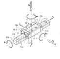
- FIG. 1 is an overall view of a life diagnosis system for a motion guide apparatus according to an embodiment of the present invention. It is an external appearance perspective view of the exercise
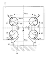
- FIG. 4A is a front view of the motion guide device viewed from the longitudinal direction of the rail, and
- FIG. 4B is an enlarged view of the B part.
- FIG. 5A is a diagram showing a first processing flow of life diagnosis executed by a computer.
- FIG. 5B is a diagram showing a second processing flow of life diagnosis executed by the computer. It is a figure which shows the change of the output of a sensor when external force acts on a carriage.
- FIG. 10 is a diagram illustrating the movement of the ball when the carriage moves on the rail.
- FIG. 11 is a graph with the horizontal axis representing the position of the carriage detected by the linear encoder and the vertical axis representing the displacement detected by the sensor.
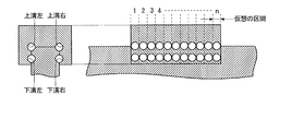
- FIG. 12 is a diagram illustrating an example of a virtual section that divides a rolling surface.
- FIG. 13 is a diagram showing an example of a count value of the maximum shear stress repeatedly generated on the rolling surface when the carriage is moving.
- FIG. 14 is a diagram showing an example of the SN curve of the material.
- Embodiment shown below is an example of embodiment of this invention, and does not limit the technical scope of this invention to the following aspects.
- FIG. 1 shows an overall view of the life diagnosis system of the motion guide device of the present embodiment.
- Reference numeral 1 is a motion guide device
- reference numerals 2a to 2d and 3a to 3d are sensors
- reference numeral 4 is a linear encoder
- reference numeral 5 is a data logger
- reference numeral 6 is a computer (an example of the “life diagnosis device” in this application).
- the motion guide device 1 is an example of a rail 11 (an example of a “track member” in the present application) and a carriage 12 (an “moving member” in the present application) that is assembled so as to be relatively movable along the longitudinal direction of the rail 11. And).
- the rail 11 is attached to the base 7 of the actual machine, and the table 8 (see FIG. 9) of the actual machine is attached to the carriage 12.
- the actual machine is, for example, a robot, a machine tool, a semiconductor, or a liquid crystal manufacturing apparatus.
- the movement direction of the movable part including the table 8 is guided by the movement guide device 1.
- the motion guide device 1 may be used in a state where the longitudinal direction of the rail 11 is not horizontal but is inclined or orthogonal to a horizontal plane.
- FIG. 2 is an external perspective view of the motion guide device 1.
- the rail 11 is arranged on a horizontal plane, and the direction of the rail 11 when viewed from the longitudinal direction, that is, the x-axis direction shown in FIG. 2, the y-axis is the up-down direction, and the z-axis is the left-right direction. 1 will be described.
- the arrangement of the motion guide device 1 is not limited to such an arrangement.
- the upper and lower two rolling surfaces 11 a are provided on both the left and right sides of the rail 11.
- the cross section of the rolling surface 11a is arcuate.
- through holes 11b through which a fastening member for fastening the rail 11 to the base 7 is passed are provided at an appropriate pitch along the longitudinal direction.
- the carriage 12 has a horizontal portion 12-1 facing the upper surface of the rail 11 and a pair of sleeve portions 12-2 facing the side surface of the rail 11, and has a U-shaped cross section.
- the carriage 12 is arranged at both ends in the movement direction of the carriage body 13 at the center in the movement direction, a pair of lid members 14a and 14b arranged at both ends in the movement direction of the carriage body 13, and a pair of lid members 14a and 14b.
- a pair of sensor mounting members 15a and 15b (see FIG. 1).
- the lid members 14a and 14b have a horizontal portion 14-1 facing the upper surface of the rail 11 and a pair of sleeve portions 14-2 facing the side surface of the rail 11, and have a U-shaped cross section.
- the sensor mounting members 15a and 15b also have a horizontal portion 15-1 facing the upper surface of the rail 11 and a pair of sleeve portions 15-2 facing the side surface of the rail 11, and have a U-shaped cross section ( (See FIG. 4 (a)).
- the lid members 14a and 14b are fastened to the carriage body 13 by fastening members such as bolts.
- the sensor attachment members 15a and 15b are fastened to the carriage body 13 and the lid members 14a and 14b by fastening members such as bolts. In FIG. 2 and FIG. 3, the sensor mounting members 15a and 15b are omitted.
- FIG. 3 is a diagram showing an outline of the internal structure of the motion guide device 1.
- the carriage body 13 is provided with four rolling surfaces 13 a facing the four rolling surfaces 11 a of the rail 11.
- the carriage body 13 is provided with a return path 13b in parallel with each rolling surface 13a.
- the lid members 14a and 14b are provided with U-shaped direction change paths 14c that connect the respective rolling surfaces 13a and the respective return paths 13b.
- the inner peripheral side of the direction change path 14 c is configured by an inner peripheral portion 13 c that is integral with the carriage body 13 and has a semicircular cross section.
- a track-shaped circulation path is constituted by the load rolling path between the rolling surface 11a of the rail 11 and the rolling surface 13a of the carriage body 13, the pair of direction changing paths 14c, and the return path 13b.
- a plurality of balls 16 are accommodated in the circulation path.
- the balls 16 interposed therebetween roll on the load rolling path.
- the ball 16 rolled to one end of the load rolling path is introduced into one direction changing path 14c, and returns to the other end of the load rolling path via the return path 13b and the other direction changing path 14c.
- the sensors 2a to 2d and 3a to 3d are, for example, capacitive displacement meters, and detect the displacement of the carriage 12 with respect to the rail 11 in a non-contact manner (an enlarged view of FIG. 4B). reference).
- the pair of sensor attachment members 15a and 15b are attached to both ends of the carriage 12 in the moving direction.
- Four sensors 2a to 2d are attached to one sensor attachment member 15a.
- the four sensors 2a to 2d are arranged at the same position in the longitudinal direction of the rail 11.
- Four sensors 3a to 3d are also attached to the other sensor attachment member 15b.
- the four sensors 3a to 3d are arranged at the same position in the longitudinal direction of the rail 11.
- the distance between the sensors 2a ⁇ 2d and the sensors 3a ⁇ 3d in the longitudinal direction of the rail 11 is L 1 (see Figure 1).
- the sensors 2a to 2d and 3a to 3d can be arranged so as to be shifted from each other along the moving direction of the carriage 12.
- FIG. 4 shows the sensor mounting member 15 a as viewed from the longitudinal direction of the rail 11.
- the sensor mounting member 15a includes the horizontal portion 15-1 facing the upper surface 11c of the rail 11, and the pair of sleeve portions 15-2 facing the left and right side surfaces of the rail 11.
- Two sensors 2a and 2b that detect displacement in the radial direction are arranged in the horizontal portion 15-1.
- the sensors 2a and 2b face the upper surface 11c of the rail 11 with a gap therebetween, and detect the gap to the upper surface 11c of the rail 11.
- Two sensors 2a, the distance in the lateral direction between 2b is L 2.
- Two sensors 2c and 2d for detecting a displacement in the horizontal direction are arranged on the pair of sleeve portions 15-2.
- the sensors 2c and 2d face each other with a gap on the side surface 11d of the rail 11, and detect the gap to the side surface 11d.
- the sensors 2a and 2b and the sensors 2c and 2d are disposed below the upper surface (mounting surface) of the carriage 12. This is because the table 8 is mounted on the upper surface (mounting surface) of the carriage 12.
- the cables 2a 1 to 2d 1 of the sensors 2a to 2d are pulled out in the left-right direction from the sleeve portion 15-2 of the sensor mounting member 15a. Note that the cables 2a 1 to 2d 1 can be drawn forward from the front surface of the sensor mounting member 15a (in a direction perpendicular to the paper surface).
- the height of the upper surface of the sensor mounting member 15a is made lower than the upper surface (mounting surface) of the carriage 12, and the gap between the upper surface of the sensor mounting member 15a and the table 8 is used as a gap for pulling out the cables 2a 1 and 2b 1. You can also
- the sensor mounting member 15b shown in FIG. 1 has a horizontal portion 15-1 and a pair of sleeve portions 15-2, and the sensors 3a to 3d correspond to the sensors 2a to 2d, respectively. Placed in.
- the linear encoder 4 detects the position of the carriage 12 in the x-axis direction.
- the linear encoder 4 includes a scale attached to the base 7 or the rail 11 of the actual machine, and a head that is attached to the table 8 or the carriage 12 of the actual machine and reads the scale.
- the position detecting means for detecting the position of the carriage 12 on the rail 11 is not limited to the linear encoder.
- a rotary encoder that detects the angle of a motor that drives the ball screw can also be used as the position detection means.
- the displacement information of the carriage 12 detected by the sensors 2a to 2d and 3a to 3d is recorded on the data logger 5 which is a recorder at every predetermined sampling period. Position information of the carriage 12 detected by the linear encoder 4 is also recorded in the data logger 5 at predetermined sampling periods.
- the data logger 5 transmits the recorded displacement information and position information to the computer 6 via wired or wireless communication means.
- the data logger 5 is arranged in the vicinity of the actual machine.
- the computer 6 is arranged near the actual machine or in a remote place.
- Sensors 2a to 2d and 3a to 3d detect the amount of displacement of the carriage 12 with respect to the rail 11.
- the displacement amount of the carriage 12 with respect to the rail 11 is a difference from the detection values of the sensors 2a to 2d and 3a to 3d in a no-load state in which no load is applied to the carriage 12. Therefore, in the data logger 5 to which displacement information is sent from the sensors 2a to 2d and 3a to 3d, the sensors 2a to 2d in the unloaded state stored in advance are calculated from the values of the displacement information sent from the sensors 2a to 2d and 3a to 3d. , 3a to 3d are recorded as the displacement of the carriage 12 relative to the rail 11.
- FIG. 5A is a diagram showing a first processing flow of life diagnosis executed by the computer 6.
- FIG. 5B is a diagram showing a second processing flow of life diagnosis executed by the computer 6.
- the computer 6 wavings when the carriage 12 is moving along the track of the rail 11 by repeatedly executing the first processing flow shown in FIG. 5A while the actual machine using the motion guide device 1 is operating. Acquire data on cyclic load associated with. Then, the computer 6 performs the second processing flow shown in FIG.
- the life diagnosis based on the data generated in the first processing flow is performed by executing at an irregular timing such as during maintenance of the actual machine.
- the computer 6 acquires the displacement amount of the carriage 12 from each of the sensors 2a to 2d and 3a to 3d (S101).
- the acquired displacement amount of the carriage 12 is recorded in the data logger 5.
- the computer 6 calculates a load acting on the carriage 12 based on the displacement amount data of the carriage 12 acquired in step S101 (S102).
- the calculated load is used to calculate the stress generated in each part of the rolling surface 13a of the carriage body 13.
- the computer 6 first determines whether or not the carriage 12 is moving based on the position information of the carriage 12 detected by the linear encoder 4. (S103).
- Flaking occurs when shear stress from the rolling surface 13a receiving the load of the balls 16 is repeatedly applied to a position slightly deeper than the rolling surface 13a, and the material forming the rolling surface 13a is fatigued.
- the repetitive load caused by the waving during the movement of the carriage 12 is the main cause of repeatedly generating shear stress at a position slightly deeper than the rolling surface 13a. Therefore, the computer 6 makes a positive determination in step S103. If this is the case, the top of the waving is detected based on the displacement amount and position information of the carriage 12 (S104).
- step S104 the computer 6 calculates the shear stress generated in each part of the rolling surface 13a when the carriage 12 is moving based on the load calculated in step S102. Then, the count value is added to the counter that counts the stress magnitude and the number of occurrences of stress for each part of the rolling surface 13a (S105). If the detection of the apex of the waving is not performed in S104, the calculation process ends.
- the first processing flow is repeatedly applied to each part of the rolling surface 13a of the carriage 12 by the load amplitude when the carriage 12 is moving.
- the number of occurrences of the shear stress is totaled for each part of the magnitude of the stress and the rolling surface 13a.
- the aggregated data is used for grasping the fatigue of each part of the rolling contact surface 13a that progresses with a repeated load in the second processing flow that will be described next.
- the computer 6 uses the data of the number of occurrences of stress for each part of the rolling surface 13 that is aggregated by repeatedly executing the first processing flow, and is sometimes called a linear cumulative damage law (“minor law”). ) Is used to calculate the life attainment rate (S201). Then, the computer 6 calculates the remaining usable distance (period) of the carriage 12 (S202).
- minor law linear cumulative damage law
- the computer 6 acquires the displacement amount of the carriage 12 from the sensors 2a to 2d and 3a to 3d. Since the measured values of the sensors 2a to 2d and 3a to 3d are the distances from the sensors to the rolling surfaces, the computer 6 calculates the distances from the sensors to the rolling surfaces when no load is applied to the carriage 12. As a reference, the difference from this distance is stored in the data logger 5 as the displacement amount of the carriage 12.
- step S102 The computer 6 calculates a load acting on the carriage 12 based on the displacement of the carriage 12.
- the computer 6 first calculates five displacement components of the carriage 12 based on the displacement amount of the carriage 12 acquired from the sensors 2a to 2d and 3a to 3d.
- the computer 6 calculates a load and a contact angle acting on each of the plurality of balls 16 based on the five displacement components.
- the computer 6 calculates a load (five components of external force) acting on the carriage 12 based on the load and contact angle of each ball 16. The above three steps will be described in detail below.
- the moments about the xyz coordinate axes are M a that is the sum of pitching moments, M b that is the sum of yawing moments, and M c that is the sum of rolling moments.
- a radial load F y , a pitching moment M a , a rolling moment M c , a horizontal load F z , and a yawing moment M b act on the carriage 12 as external forces.
- the corresponding displacement five components that is, radial displacement ⁇ 1 (mm), pitching angle ⁇ 2 (rad), rolling angle ⁇ 3 (rad), horizontal, A displacement ⁇ 4 (mm) and a yawing angle ⁇ 5 (rad) are generated.
- FIG. 6 shows changes in the outputs of the sensors 2a to 2d when an external force is applied to the carriage 12.
- FIG. 6 the hatched arrow is a sensor whose output changes
- the white arrow in FIG. 6 is a sensor whose output does not change.
- the five displacement components of the carriage 12 can be calculated based on the displacements detected by the sensors 2a to 2d and 3a to 3d.
- FIG. 7 shows a state in which a portion in contact with the ball 16 in the carriage 12 is a cross section in the x-axis direction.
- each ball pitch is set to ⁇ Da using ⁇ having a value slightly larger than 1, and the x coordinate of each ball is determined, which is set to X i .
- the number of balls lined up within 2U x is called the effective number of balls and is designated as I.
- the end portions of the carriage 12, a large curved surface machining of R shape depth in radius R is called crowning such that lambda epsilon is applied.
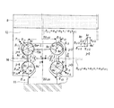
- FIG. 8 shows the state of the internal load before the displacement 5 component is generated in the inner cross section of the carriage 12 at the ball number i of the carriage 12, and
- FIG. 9 shows the state of the internal load after the displacement 5 component is generated.
- the ball number of the carriage 12 is j
- the ball number in the ball row is i.
- the ball diameter is D a
- the matching degree between the rolling surface and the ball 16 is f on both the rail 11 side and the carriage 12 side, that is, the rolling surface curvature radius is fD a .
- the rail-side rolling surface curvature center position is A r
- the carriage-side rolling surface curvature center position is Ac
- the initial state of the contact angle that is the angle between the line connecting them and the z-axis is ⁇ .
- the distance between the ball centers of the balls 16 that roll on the two rolling surfaces on the upper side of the rail 11 is 2U z12
- the distance is 2U z34
- the center-to-ball distance between the balls 16 rolling on the upper rolling surface and the lower rolling surface of the rail 11 is 2U y .
- Preload is acting on the ball 16.
- the dimensions of the portion sandwiched between the rolling surfaces of the rail 11 and the carriage 12 that are opposed to each other are determined by the design dimensions of the rail 11 and the carriage 12 and the geometric shape of the rolling surface.
- the ball diameter to be entered is the ball diameter at the time of design, but if the ball 16 having a size Da + ⁇ slightly larger than the ball diameter at the time of design is incorporated therein, the contact portion between the ball 16 and the rolling surface is the contact of Hertz. By theory, it elastically deforms, forms a contact surface, and generates contact stress.
- the load thus generated is an internal load and a preload load.
- the load is represented by P 0
- the mutual approach amount between the rail 11 and the carriage 12 due to the elastic deformation of the contact portion is represented by ⁇ 0 .
- the ball position is located at the center position between the rolling surfaces of the rail 11 and the carriage 12 depicted by the alternate long and short dash line in FIG. 8, but the degree of fit f between the balls 16 on both rolling surfaces is equal.
- Various characteristic values based on Hertz's contact theory generated at two contact portions are the same. For this reason, the ball 16 is drawn while being shifted to the rail-side rolling surface position so that the mutual approach amount ⁇ 0 between the rolling surfaces of the rail 11 and the carriage 12 is easily understood.
- the preload is defined as the radial load of the upper two rows (or the lower two rows) per carriage, so the preload P pre is expressed by the following equation. (Equation 6)
- the center of the motion guide apparatus 1 with the coordinate origin as the origin is the i-th position by the radial displacement ⁇ 1 , the pitching angle ⁇ 2 , the rolling angle ⁇ 3 , the horizontal displacement ⁇ 4 , and the yawing angle ⁇ 5 .
- the relative displacement between the rail 11 and the carriage 12 occurs at the ball position.
- a c is expressed as movement A c 'f is a carriage-side rolling surface curvature center.
- the carriage 12 of the rolling surface the center of curvature of the side Ac' has a shape away from the rail side rolling surface curvature center a c, less that extent. Since it can be regarded as equivalent to a ball diameter that is reduced to a value corresponding to it, the amount is subtracted in the above equation as ⁇ xi .
- the rolling element load P ij is obtained from the elastic deformation amount ⁇ ij by the following equation.
- Cb is a non-linear spring constant (N / mm 3/2 ) and is given by the following equation.
- Equation 13 E is the longitudinal elastic modulus, 1 / m is the Poisson's ratio, 2K / ⁇ is the Hertz coefficient, and ⁇ is the principal curvature sum.
- the contact angle ⁇ ij , the elastic deformation amount ⁇ ij , and the rolling element load P ij can be expressed by equations for all the balls 16 in the carriage 12 using the displacement five components ⁇ 1 to ⁇ 5 of the carriage 12. It ’s done.
- the rigid model load distribution theory in which the carriage 12 is considered as a rigid body is used.
- the rigid body model load distribution theory can be expanded to use the carriage beam model load distribution theory in which the beam theory is applied to take into account the deformation of the sleeve 12-2 of the carriage 12.
- a carriage rail FEM model load distribution theory in which the carriage 12 and the rail 11 are FEM models can be used.
- step S103 The computer 6 determines whether or not the carriage 12 is moving. Whether or not the carriage 12 is moving can be determined based on the position information of the carriage 12 detected by the linear encoder 4. For example, if the position information of the carriage 12 detected by the linear encoder 4 changes in time series, the computer 6 determines that the carriage 12 is moving, and if the position information does not change in time series, the carriage 12 stops. Judged as medium.
- step S104 Next, details of step S104 will be described.
- the computer 6 detects the apex of the waving based on the displacement amount and position information of the carriage 12 recorded in the data logger 5.
- FIG. 10 is a view showing the movement of the ball 16 when the carriage 12 moves on the rail 11.
- the carriage 12 includes a plurality of balls 16, and the ball 16 that supports the carriage 12 among the plurality of balls 16 is sandwiched between the rolling surface 11 a of the rail 11 and the rolling surface 13 a of the carriage body 13. Is a ball 16 (the ball 16 which is hatched in FIG. 10).
- FIG. 10A the ball 16 which is hatched in FIG. 10
- the number of balls 16 sandwiched between the rolling surface 11a of the rail 11 and the rolling surface 13a of the carriage body 13 is as follows.
- the increase / decrease is repeated as the carriage 12 moves relative to the rail 11.
- This repetition cycle coincides with the cycle in which the carriage 12 moves by the same amount as the pitch between the balls 16 adjacent to the rail 11. Therefore, the top of the waving is the relative between the ball 16 that rolls when the carriage 12 moves on the rail 11 and the rolling surfaces 11a and 13a among the displacement waveforms detected by the sensors 2a to 2d and 3a to 3d. This is the peak of the wave that matches the period of position shift.
- the computer 6 when detecting the vertex of the waving, the computer 6 first obtains each of the five displacement components from the position of the carriage 12 on the rail 11 obtained from the linear encoder 4 and from the sensors 2a to 2d and 3a to 3d. Analyze data representing the relationship with displacement. Then, the computer 6 determines the presence / absence of data representing the waving from the data representing the relationship between the position of the carriage 12 and the displacement amount.
- the presence / absence of data indicating waving is, for example, substantially the same period as the pitch of the balls 16 when a waveform of a graph with the horizontal axis as the position on the rail 11 of the carriage 12 and the vertical axis as the displacement amount of the carriage 12 is imaged. If there is a peak appearing at, it is determined that there is waving, and if there is no peak appearing at substantially the same period as the pitch of the balls 16, it is determined that there is no waving.
- FIG. 11 is a graph with the position on the rail 11 of the carriage 12 detected by the linear encoder 4 as the horizontal axis and the displacement detected by the sensors 2a to 2d and 3a to 3d as the vertical axis.
- the carriage 12 is provided with eight sensors 2a to 2d and 3a to 3d. Since the carriage 12 reciprocates on the rail 11, there are inherently a plurality of lines indicating the relationship between the position and displacement of the carriage 12. . However, in order to facilitate understanding, in the graph of FIG. 11, the relationship between the position of the carriage 12 and the displacement is indicated by a single broken line. As can be seen from the graph of FIG. 11, it can be seen that the displacement of the carriage 12 includes two types of vibration components, a relatively slow displacement and a relatively fine displacement.
- the relatively slow displacement of the former is considered to be a vibration component other than waving due to, for example, the accuracy of the rolling surface 11 a of the rail 11.
- the latter relatively small displacement is a vibration component caused by waving, and is a displacement generated when the carriage 12 is moving on the rail 11.
- the distance between the vertices of the vertices of the relatively fine displacement shown in the graph of FIG. 11 approximately matches the pitch of the balls 16.
- the computer 6 uses the data representing the relationship between the position of the carriage 12 on the rail 11 and the amount of displacement, as shown in the graph of FIG.
- the vibration component is detected, and the peak of the vibration component waveform is detected.
- the computer 6 detects the apex of the waveform of the waving when the waving is detected from the displacement data detected by any one or more of the plurality of sensors 2a to 2d and 3a to 3d.
- ⁇ S105> When the computer 6 detects the apex of the waveform of the waving in step S104, based on the load calculated in step S102, the computer 6 generates the maximum shear stress generated on the rolling surface 13a of the carriage 12 (the “stress during movement” in the present application). Is an example). In this embodiment, in order to grasp the life due to local fatigue of the rolling contact surface 13a, the computer 6 divides the rolling contact surface 13a along the direction of the track for calculation of the maximum shear stress generated on the rolling contact surface 13a. This is done for each virtual section.
- FIG. 12 is a diagram illustrating an example of a virtual section that divides the rolling surface 13a.
- the maximum shear stress is calculated for each virtual section obtained by dividing the rolling surface 13a by the number of effective balls.
- the shear stress generated in each section of the rolling surface 13a divided in this way is applied to the rolling element load P ij described in the description of step S102 and the contact portion between the sphere and the plane. It can be calculated according to an equation created in advance using an analysis model of the generated strain.
- FIG. 13 is a diagram showing an example of a count value of the maximum shear stress repeatedly generated on the rolling surface 13a when the carriage 12 is moving.
- the computer 6 classifies the magnitude of the stress stepwise for every 50 MPa, and sets the counter value of the category corresponding to the calculated maximum shear stress for each waving, in other words, FIG. 11. 1 is added every time the vertex occurs in the waving waveform shown in FIG. Therefore, the counter value increases in proportion to the integrated movement distance of the carriage 12.
- the number of occurrences of stress that causes the rolling surface 13a to fatigue is aggregated for each magnitude and section of the stress, for example, locally repeated stress is generated in a specific section of the rolling surface 13a. Even if it is a case, the basic data for a diagnosis which can reflect the local fatigue
- movement guidance apparatus 1 are obtained.
- the computer 6 calculates the life attainment rate using the totaled result obtained by repeatedly executing the first processing flow.
- the life achievement rate is calculated for each section of the rolling surface 13a.
- the value with the highest life arrival rate among the calculated life arrival rates of all the sections is adopted for the life diagnosis of the motion guide apparatus 1.
- the life attainment rate is calculated using, for example, a linear cumulative damage law.
- FIG. 14 is a diagram showing an example of the SN curve of the material.
- the linear cumulative damage law predicts the life until damage is caused by fatigue when an object is repeatedly subjected to stress in material fatigue. Therefore, the stress is repeated due to the load amplitude generated during the movement of the carriage 12. It is effective for grasping the fatigue of the material.
- the remaining usable distance of the carriage 12 is determined using the value with the highest life reachability among the life reach rates of all the sections calculated for each section of the rolling surface 13a. (Period) is calculated.
- the usable distance (period) is, for example, the case where the life achievement rate D becomes 1 according to the linear cumulative damage law. Therefore, the available distance D Life is the accumulated moving distance of the carriage 12 obtained from the position information from the linear encoder 4 When D int, can be expressed by the following equation.
- T Life (1-D) / D * D int
- T int the elapsed time from the start of use of the linear encoder 4 to the calculation of the life attainment rate D.
- T Life (1-D) / D * T int
- the computer 6 uses the waving frequency at which the ball 16 repeatedly applies stress to the rolling surface 13a of the carriage 12 for the life diagnosis. Therefore, the computer 6 is more accurate than the life diagnosis performed without using the waving frequency. A diagnostic result is obtained.
- the computer 6 counts the vibration frequency of the waving with the displacement information of the sensors 2a, 2b, 3a, and 3b that are also used to calculate the stress generated on the rolling surface 13a of the carriage 12, The apparatus configuration is less complicated than the case of separately providing sensors for counting the frequency. Further, since the computer 6 calculates the stress for each virtual section obtained by dividing the rolling surface 13a of the carriage 12 along the direction of the track, the life diagnosis based on the stress of the entire rolling surface 13a is used. High diagnostic results can be obtained.
Landscapes
- Physics & Mathematics (AREA)
- General Physics & Mathematics (AREA)
- Engineering & Computer Science (AREA)
- General Engineering & Computer Science (AREA)
- Mechanical Engineering (AREA)
- Chemical & Material Sciences (AREA)
- Analytical Chemistry (AREA)
- Bearings For Parts Moving Linearly (AREA)
- Testing Of Devices, Machine Parts, Or Other Structures Thereof (AREA)
Abstract
本願は、寿命を高精度に診断可能な運動案内装置の寿命診断装置、方法、プログラムおよびシステムを開示する。軌道部材に複数の転動体を介して移動部材を相対移動可能に組み付けた運動案内装置の寿命診断装置であって、軌道部材が形成する軌道に対する移動部材の変位量を基に、移動部材の転動面を軌道の方向沿いに区分けした仮想の区間毎に、移動部材が移動している際に各区間に発生する応力である移動時応力を算出する応力算出手段と、移動部材が軌道沿いに移動する際のウェービングに伴い繰り返し発生する移動時応力の発生回数を、変位量を基に区間毎にカウントするカウント手段と、移動時応力の大きさと移動時応力の発生回数とに基づく寿命到達率の算出を区間毎に行い、算出した各区間の寿命到達率を基に運動案内装置の寿命診断を行う診断手段と、を備える。
Description
本願は、運動案内装置の寿命診断装置、方法、プログラムおよびシステムを開示する。
ロボットや工作機械、半導体・液晶製造装置等の各種装置類には、可動部の進路を案内するための部品が用いられる。例えば、可動部が直進する箇所にはリニアガイドが用いられる。このような部品の選定に際しては、通常、安全係数を乗じた荷重に対して余裕のある定格荷重を持つものが選定されるが、近年では、例えば、部品に歪ゲージを取り付け、部品に加わる実荷重を算出して部品をより適格に管理する試みも行われている(例えば、特許文献1を参照)。
可動部の進路を案内する運動案内装置は、転動体が接する転動面を形成する材料に疲労が蓄積すると、案内精度が低下する可能性がある。そこで、転動面を形成する材料の疲労を把握するべく、転動面に加わる荷重を測定し、寿命診断を行うことが考えられるが、例えば、上述の歪ゲージを用いた実荷重の測定方式を用いる場合、歪ゲージでは転動面の疲労を部位毎に捉えることが難しいため、転動面の局部的な疲労による寿命を予測することが難しい。
そこで、本願は、寿命を高精度に診断可能な運動案内装置の寿命診断装置、方法、プログラムおよびシステムを開示する。
上記課題を解決するため、本発明では、運動案内装置の軌道部材が形成する軌道に対する移動部材の変位量を基に、転動面を区分けした仮想の区間毎に各区間の発生応力を算出し、応力の発生回数を区間毎にカウントし、応力の大きさと発生回数とに基づいて算出される各区間の寿命到達率から運動案内装置の寿命診断を行うことにした。
詳細には、本発明は、軌道部材に複数の転動体を介して移動部材を相対移動可能に組み付けた運動案内装置の寿命診断装置であって、軌道部材が形成する軌道に対する移動部材の変位量を基に、移動部材の転動面を軌道の方向沿いに区分けした仮想の区間毎に、移動部材が移動している際に各区間に発生する応力である移動時応力を算出する応力算出手段と、移動部材が軌道沿いに移動する際のウェービングに伴い繰り返し発生する移動時応力の発生回数を、変位量を基に区間毎にカウントするカウント手段と、移動時応力の大きさと移動時応力の発生回数とに基づく寿命到達率の算出を区間毎に行い、算出した各区間の寿命到達率を基に運動案内装置の寿命診断を行う診断手段と、を備える。
ここで、ウェービングとは、転動体の転動面に対する周期的な相対位置のずれに起因する移動部材の姿勢変化や振動(脈動)のことである。ウェービングは、移動部材の移動に伴って周期的に発生する微小な変位となって現れるため、上記の寿命診断装置では、転動体が転動面に応力を繰り返し与えて材料を疲労させることに起因する運動案内装置の寿命診断において、ウェービングに伴って繰り返される応力の発生回数をカウントし、運動診断装置の寿命診断に用いることにしている。
そして、ウェービングは、例えば、軌道部材が形成する軌道に直交する方向をラジアル方向として規定した場合に、軌道部材に対する移動部材のラジアル方向沿いの相対的な変位に振動成分となって現れるため、上記の寿命診断装置では、軌道部材が形成する軌道に対する移動部材の変位量を基に、移動部材が軌道沿いに移動する際のウェービングの振動数をカウントすることにしている。上記の寿命診断装置では、転動面に発生する応力を、軌道部材に対する移動部材の相対的な変位量を基に算出しているため、ウェービングに伴う繰り返し発生する応力の発生回数についても当該相対的な変位量を基にカウントすることで、軌道に対する移動部材の変位量のデータを有効に利用している。
ところで、上記の寿命診断装置が診断を行う運動案内装置では、軌道部材に複数の転動体を介して移動部材が相対移動可能に組み付けられているため、転動面には複数の転動体が接触している。運動案内装置は、転動面が局部的に疲労しても移動部材の進路の案内に支障を来す可能性がある。そこで、上記の寿命診断装置では、移動部材の転動面を軌道の方向沿いに区分けした仮想の区間毎に応力を算出することで、転動面全体の応力を基にした寿命診断よりも診断精度の向上を図っている。仮想の区間数は、少なくとも2以上であれば、転動面全体の応力を基にした寿命診断よりも部分的な疲労を捉えて診断精度の向上が図られることになるが、例えば、転動面に接触している転動体の個数分の区間数であれば、転動体の各区間に発生する応力と各転動体にかかる荷重との対応関係が把握しやすいため、上記移動時応力の算出が容易である。
なお、本発明は、方法、コンピュータプログラムあるいはシステムの側面から捉えることもできる。例えば、本発明は、軌道部材に複数の転動体を介して移動部材を相対移動可能に組み付けた運動案内装置の寿命診断方法であって、軌道部材が形成する軌道に対する移動部材の変位量を基に、移動部材の転動面を軌道の方向沿いに区分けした仮想の区間毎に、移動部材が移動している際に各区間に発生する応力である移動時応力を算出し、移動部材が軌道沿いに移動する際のウェービングに伴い繰り返し発生する移動時応力の発生回数を、変位量を基に区間毎にカウントし、移動時応力の大きさと移動時応力の発生回数とに基づく寿命到達率の算出を区間毎に行い、算出した各区間の寿命到達率を基に運動案内装置の寿命診断を行う、運動案内装置の寿命診断方法であってもよい。
上記の寿命診断装置、方法、プログラムおよびシステムは、運動案内装置の寿命を高精度に診断可能である。
以下、本発明の実施形態について説明する。以下に示す実施形態は、本発明の実施形態の一例であり、本発明の技術的範囲を以下の態様に限定するものではない。
図1は、本実施形態の運動案内装置の寿命診断システムの全体図を示す。符号1が運動案内装置、符号2a~2d,3a~3dがセンサ、符号4がリニアエンコーダ、符号5がデータロガー、符号6がコンピュータ(本願でいう「寿命診断装置」の一例である)である。
まず、運動案内装置1の構成を説明する。運動案内装置1は、レール11(本願でいう「軌道部材」の一例である)と、レール11の長手方向沿いに相対移動可能に組み付けられるキャリッジ12(本願でいう「移動部材」の一例である)と、を備える。この実施形態では、レール11が実機のベース7に取り付けられ、キャリッジ12に実機のテーブル8(図9参照)が取り付けられる。実機は、例えば、ロボット、工作機械、半導体又は液晶製造装置等である。テーブル8を含む可動部の運動方向は、運動案内装置1によって案内される。なお、運動案内装置1を上下反転し、キャリッジ12をベース7に取り付け、レール11をテーブル8に取り付けることもできる。また、運動案内装置1は、レール11の長手方向が水平でなく、水平面に対して傾斜し或いは直交する状態で用いられてもよい。
図2は、運動案内装置1の外観斜視図を示す。説明の便宜上、レール11を水平面に配置し、レール11の長手方向から見たときの方向、すなわち図2に示すx軸を前後方向、y軸を上下方向、z軸を左右方向として運動案内装置1の構成を説明する。もちろん、運動案内装置1の配置は、このような配置に限られることはない。
レール11の左右の両側それぞれには、上下二条の転動面11aが設けられる。転動面11aの断面は円弧状である。レール11の上面には、レール11をベース7に締結するための締結部材が通される通し孔11bが長手方向沿いに適当なピッチで設けられる。
キャリッジ12は、レール11の上面に対向する水平部12-1と、レール11の側面に対向する一対の袖部12-2と、を有し、断面コの字状である。キャリッジ12は、移動方向の中央のキャリッジ本体13と、キャリッジ本体13の移動方向の両端に配置される一対の蓋部材14a,14bと、一対の蓋部材14a,14bの移動方向の両端に配置される一対のセンサ取付け部材15a,15b(図1参照)と、を備える。蓋部材14a,14bは、レール11の上面に対向する水平部14-1と、レール11の側面に対向する一対の袖部14-2と、を有し、断面コの字状である。センサ取付け部材15a,15bも、レール11の上面に対向する水平部15-1と、レール11の側面に対向する一対の袖部15-2と、を有し、断面コの字状である(図4(a)参照)。蓋部材14a,14bは、ボルト等の締結部材によってキャリッジ本体13に締結される。センサ取付け部材15a,15bは、ボルト等の締結部材によってキャリッジ本体13及び蓋部材14a,14bに締結される。なお、図2、図3では、センサ取付け部材15a,15bが省略されている。
図3は、運動案内装置1の内部構造の概要を示した図である。図3に示すように、キャリッジ本体13には、レール11の四条の転動面11aに対向する四条の転動面13aが設けられる。キャリッジ本体13には、各転動面13aと平行に戻し路13bが設けられる。蓋部材14a,14bには、各転動面13aと各戻し路13bとを繋げるU字状の方向転換路14cが設けられる。方向転換路14cの内周側は、キャリッジ本体13と一体の断面半円状の内周部13cによって構成される。レール11の転動面11aとキャリッジ本体13の転動面13aとの間の負荷転走路、一対の方向転換路14c、戻し路13bによってトラック状の循環路が構成される。循環路には、複数の玉16(本願でいう「転動体」の一例である)が収容される。レール11に対してキャリッジ12が相対的に移動すると、これらの間に介在する玉16が負荷転走路を転がる。負荷転走路の一端まで転がった玉16は、一方の方向転換路14cに導入され、戻し路13b、他方の方向転換路14cを経由して、負荷転走路の他端に戻る。
<センサの構成>
図1に示すように、センサ2a~2d,3a~3dは、例えば静電容量式の変位計であり、レール11に対するキャリッジ12の変位を非接触で検出する(図4(b)の拡大図参照)。上記のように、キャリッジ12の移動方向の両端部には、一対のセンサ取付け部材15a,15bが取り付けられる。一方のセンサ取付け部材15aには、4つのセンサ2a~2dが取り付けられる。4つのセンサ2a~2dは、レール11の長手方向において同一の位置に配置される。他方のセンサ取付け部材15bにも、4つのセンサ3a~3dが取り付けられる。4つのセンサ3a~3dは、レール11の長手方向において同一の位置に配置される。レール11の長手方向におけるセンサ2a~2dとセンサ3a~3dとの間の距離はL1である(図1を参照)。なお、各センサ2a~2d,3a~3dをキャリッジ12の移動方向沿いに互いにずらして配置することも可能である。
図1に示すように、センサ2a~2d,3a~3dは、例えば静電容量式の変位計であり、レール11に対するキャリッジ12の変位を非接触で検出する(図4(b)の拡大図参照)。上記のように、キャリッジ12の移動方向の両端部には、一対のセンサ取付け部材15a,15bが取り付けられる。一方のセンサ取付け部材15aには、4つのセンサ2a~2dが取り付けられる。4つのセンサ2a~2dは、レール11の長手方向において同一の位置に配置される。他方のセンサ取付け部材15bにも、4つのセンサ3a~3dが取り付けられる。4つのセンサ3a~3dは、レール11の長手方向において同一の位置に配置される。レール11の長手方向におけるセンサ2a~2dとセンサ3a~3dとの間の距離はL1である(図1を参照)。なお、各センサ2a~2d,3a~3dをキャリッジ12の移動方向沿いに互いにずらして配置することも可能である。
図4は、レール11の長手方向から見たセンサ取付け部材15aを示す。上記のように、センサ取付け部材15aは、レール11の上面11cに対向する水平部15-1と、レール11の左右側面に対向する一対の袖部15-2と、を有する。水平部15-1には、ラジアル方向の変位を検出する2つのセンサ2a,2bが配置される。センサ2a,2bは、レール11の上面11cに隙間をあけて向かい合っており、レール11の上面11cまでの隙間を検出する。2つのセンサ2a,2b間の左右方向における距離はL2である。
一対の袖部15-2には、水平方向の変位を検出する2つのセンサ2c,2dが配置される。センサ2c,2dは、レール11の側面11dに隙間をあけて向かい合っており、側面11dまでの隙間を検出する。
レール11を水平面に配置したと仮定した状態において、センサ2a,2b及びセンサ2c,2dは、キャリッジ12の上面(取付け面)よりも下方に配置される。キャリッジ12の上面(取付け面)の上にテーブル8を取り付けるためである。センサ2a~2dのケーブル2a1~2d1は、センサ取付け部材15aの袖部15-2から左右方向に引き出される。なお、ケーブル2a1~2d1をセンサ取付け部材15aの前面から前方に(紙面に垂直方向に)引き出すこともできる。また、センサ取付け部材15aの上面の高さをキャリッジ12の上面(取付け面)よりも低くし、センサ取付け部材15aの上面とテーブル8との隙間をケーブル2a1,2b1を引き出す隙間として利用することもできる。
図1に示すセンサ取付け部材15bも、センサ取付け部材15aと同様に、水平部15-1と一対の袖部15-2とを有し、センサ3a~3dがセンサ2a~2dにそれぞれ対応する位置に配置される。
<リニアエンコーダの構成>
リニアエンコーダ4は、キャリッジ12のx軸方向の位置を検出する。例えば、リニアエンコーダ4は、実機のベース7又はレール11に取り付けられるスケールと、実機のテーブル8又はキャリッジ12に取り付けられ、スケールを読み取るヘッドと、を備える。なお、レール11上のキャリッジ12の位置を検出する位置検出手段は、リニアエンコーダに限定されるものではない。例えば、実機のテーブルがボールねじ駆動の場合、位置検出手段として、ボールねじを駆動するモータの角度を検出するロータリーエンコーダを用いることもできる。
リニアエンコーダ4は、キャリッジ12のx軸方向の位置を検出する。例えば、リニアエンコーダ4は、実機のベース7又はレール11に取り付けられるスケールと、実機のテーブル8又はキャリッジ12に取り付けられ、スケールを読み取るヘッドと、を備える。なお、レール11上のキャリッジ12の位置を検出する位置検出手段は、リニアエンコーダに限定されるものではない。例えば、実機のテーブルがボールねじ駆動の場合、位置検出手段として、ボールねじを駆動するモータの角度を検出するロータリーエンコーダを用いることもできる。
<データロガー、コンピュータの構成>
センサ2a~2d,3a~3dが検出したキャリッジ12の変位情報は、所定のサンプリング周期毎に記録計であるデータロガー5に記録される。リニアエンコーダ4が検出したキャリッジ12の位置情報も、所定のサンプリング周期毎にデータロガー5に記録される。データロガー5は、記録した変位情報及び位置情報を有線又は無線通信手段を介してコンピュータ6に送信する。データロガー5は、実機の近傍に配置される。コンピュータ6は、実機の近傍又は遠隔地に配置される。
センサ2a~2d,3a~3dが検出したキャリッジ12の変位情報は、所定のサンプリング周期毎に記録計であるデータロガー5に記録される。リニアエンコーダ4が検出したキャリッジ12の位置情報も、所定のサンプリング周期毎にデータロガー5に記録される。データロガー5は、記録した変位情報及び位置情報を有線又は無線通信手段を介してコンピュータ6に送信する。データロガー5は、実機の近傍に配置される。コンピュータ6は、実機の近傍又は遠隔地に配置される。
センサ2a~2d,3a~3dは、レール11に対するキャリッジ12の変位量を検出する。レール11に対するキャリッジ12の変位量は、キャリッジ12に荷重が加わっていない無負荷状態におけるセンサ2a~2d,3a~3dの検出値からの差分である。そこで、センサ2a~2d,3a~3dから変位情報が送られるデータロガー5では、センサ2a~2d,3a~3dから送られる変位情報の値から、予め記憶された無負荷状態におけるセンサ2a~2d,3a~3dの検出値を差し引いた値が、レール11に対するキャリッジ12の変位量として記録される。
コンピュータ6は、データロガー5に記録された情報を使い、運動案内装置1の寿命診断を行う。図5Aは、コンピュータ6が実行する寿命診断の第1の処理フローを示した図である。また、図5Bは、コンピュータ6が実行する寿命診断の第2の処理フローを示した図である。コンピュータ6は、運動案内装置1が用いられている実機が稼働中、図5Aに示す第1の処理フローを繰り返し実行することにより、キャリッジ12がレール11の軌道沿いに移動している時のウェービングに伴う繰返し荷重に関するデータを取得する。そして、コンピュータ6は、図5Bに示す第2の処理フローを、例えば、第1の処理フローが100回繰り返される毎、実機が稼働している間に数分から数時間毎といった定期的なタイミング、或いは、実機のメンテナンス時といった不定期のタイミングで実行することにより、第1の処理フローで生成したデータを基にした寿命診断を行う。
<寿命診断の概要>
まず、図5Aに示す第1の処理フローの概要について説明する。
まず、図5Aに示す第1の処理フローの概要について説明する。
運動案内装置1が用いられている実機の稼働中、コンピュータ6は、各センサ2a~2d,3a~3dからキャリッジ12の変位量を取得する(S101)。取得されたキャリッジ12の変位量は、データロガー5に記録される。そして、コンピュータ6は、ステップS101で取得したキャリッジ12の変位量のデータを基に、キャリッジ12に作用する荷重の計算を行う(S102)。
算出された荷重は、キャリッジ本体13の転動面13aの各部に発生する応力の計算に用いられる。転動面13aの各部に発生する応力を計算するにあたり、コンピュータ6は、まず、リニアエンコーダ4が検出するキャリッジ12の位置情報を基に、キャリッジ12が移動中であるか否かの判定を行う(S103)。
運動案内装置1の寿命を示す現象の一例として、転動面13aに発生するうろこ状の剥離(以下、「フレーキング」という)が挙げられる。フレーキングは、転動面13aよりやや深い位置に、玉16の荷重を受ける転動面13aからのせん断応力が繰り返し加わり、転動面13aを形成する材料が疲労することにより発生する。ここで、キャリッジ12の移動の際のウェービングに伴う繰返し荷重は、転動面13aよりやや深い位置にせん断応力を繰り返し発生させる主たる原因であるため、コンピュータ6は、ステップS103で肯定判定が行われた場合、キャリッジ12の変位量及び位置情報を基に、ウェービングの頂点の検出を行う(S104)。なお、S103で否定判定されると、本算出処理を終了する。そして、ステップS104でウェービングの頂点が検出されると、コンピュータ6は、ステップS102で算出した荷重を基に、キャリッジ12が移動している時に転動面13aの各部に発生するせん断応力を計算し、応力の大きさと転動面13aの部位毎に応力の発生回数をカウントするカウンタに対してカウント値の加算処理を行う(S105)。なお、S104でウェービングの頂点の検出が行われないと、本算出処理を終了する。
ステップS101からステップS105までの一連の処理を擁する上記第1の処理フローが繰り返し実行されることにより、キャリッジ12が移動している際の荷重振幅によってキャリッジ12の転動面13aの各部に繰り返し加わるせん断応力の発生回数が、応力の大きさと転動面13aの部位毎に集計される。集計されたデータは、次に概要を説明する第2の処理フローにおいて、繰返し荷重で進行する転動面13aの部位毎の疲労の把握に用いられることになる。
次に、図5Bに示す第2の処理フローの概要について説明する。コンピュータ6は、第1の処理フローが繰り返し実行されることで集計された転動面13の部位毎の応力の発生回数のデータを使い、線形累積損傷則(「マイナー則」と呼ばれる場合もある)を用いた寿命到達率の計算を行う(S201)。そして、コンピュータ6は、キャリッジ12の残りの使用可能距離(期間)の計算を行う(S202)。
以下、各ステップの詳細について説明する。
<S101>
運動案内装置1が用いられている実機の稼働中、コンピュータ6は、各センサ2a~2d,3a~3dからキャリッジ12の変位量を取得する。各センサ2a~2d,3a~3dの計測値はセンサから転動面までの距離であるため、コンピュータ6は、キャリッジ12に荷重が加わっていない無負荷時のセンサから転動面までの距離を基準とし、この距離からの差分をキャリッジ12の変位量としてデータロガー5に格納する。
運動案内装置1が用いられている実機の稼働中、コンピュータ6は、各センサ2a~2d,3a~3dからキャリッジ12の変位量を取得する。各センサ2a~2d,3a~3dの計測値はセンサから転動面までの距離であるため、コンピュータ6は、キャリッジ12に荷重が加わっていない無負荷時のセンサから転動面までの距離を基準とし、この距離からの差分をキャリッジ12の変位量としてデータロガー5に格納する。
<S102>
次に、ステップS102の詳細について説明する。コンピュータ6は、キャリッジ12の変位に基づいて、キャリッジ12に働く荷重を算出する。コンピュータ6は、荷重を算出するにあたって、まず、各センサ2a~2d,3a~3dから取得したキャリッジ12の変位量に基づいて、キャリッジ12の変位5成分を算出する。次に、コンピュータ6は、変位5成分に基づいて、複数の玉16それぞれに働く荷重及び接触角を算出する。次に、コンピュータ6は、各玉16の荷重及び接触角に基づいて、キャリッジ12に働く荷重(外力5成分)を算出する。上記の3工程を詳細に以下に説明する。
次に、ステップS102の詳細について説明する。コンピュータ6は、キャリッジ12の変位に基づいて、キャリッジ12に働く荷重を算出する。コンピュータ6は、荷重を算出するにあたって、まず、各センサ2a~2d,3a~3dから取得したキャリッジ12の変位量に基づいて、キャリッジ12の変位5成分を算出する。次に、コンピュータ6は、変位5成分に基づいて、複数の玉16それぞれに働く荷重及び接触角を算出する。次に、コンピュータ6は、各玉16の荷重及び接触角に基づいて、キャリッジ12に働く荷重(外力5成分)を算出する。上記の3工程を詳細に以下に説明する。
<キャリッジの変位5成分の算出>
図2に示すように、運動案内装置1にx-y-z座標軸を設定すると、x-y-z座標軸の座標原点に働く荷重は、ラジアル荷重と逆ラジアル荷重の合計であるFyと、水平荷重のFzである。キャリッジ12をレール11に押し付ける方向で、図2のy軸の正方向ヘ働く荷重がラジアル荷重である。その逆の方向、すなわちキャリッジ12をレール11から引き離す方向が逆ラジアル荷重である。キャリッジ12をレール11に対し横へずらす方向で、図2のz軸正負方向へ働く荷重が水平荷重である。
図2に示すように、運動案内装置1にx-y-z座標軸を設定すると、x-y-z座標軸の座標原点に働く荷重は、ラジアル荷重と逆ラジアル荷重の合計であるFyと、水平荷重のFzである。キャリッジ12をレール11に押し付ける方向で、図2のy軸の正方向ヘ働く荷重がラジアル荷重である。その逆の方向、すなわちキャリッジ12をレール11から引き離す方向が逆ラジアル荷重である。キャリッジ12をレール11に対し横へずらす方向で、図2のz軸正負方向へ働く荷重が水平荷重である。
また、x-y-z座標軸まわりのモーメントは、ピッチングモーメントの合計であるMaと、ヨーイングモーメントの合計であるMbと、ローリングモーメントの合計であるMcである。キャリッジ12には、外力として、ラジアル荷重Fy、ピッチングモーメントMa、ローリングモーメントMc、水平荷重Fz、ヨーイングモーメントMbが働く。キャリッジ12にこれらの外力5成分が作用すると、キャリッジ12にはそれぞれに対応する変位5成分、すなわちラジアル変位α1(mm)、ピッチング角α2(rad)、ローリング角α3(rad)、水平変位α4(mm)、ヨーイング角α5(rad)が生ずる。
図6は、キャリッジ12に外力が働くときの、センサ2a~2dの出力の変化を示す。図6において斜線のハッチング付きの矢印は、出力が変化するセンサであり、図6において白抜きの矢印は、出力が変化しないセンサである。キャリッジ12にラジアル荷重Fyが働くとき、キャリッジ12とレール11との間の上下方向の隙間が小さくなる。一方、キャリッジ12に逆ラジアル荷重-Fyが働くとき、キャリッジ12とレール11との間の上下方向の隙間が大きくなる。センサ2a,2bは、この上下方向の隙間の変化(変位)を検出する。なお、センサ取付け部材15b(図1参照)に取り付けられるセンサ3a,3bも、この上下方向の変位を検出する。
キャリッジ12にラジアル荷重Fy又は逆ラジアル荷重-Fyが働くとき、キャリッジ12のラジアル変位α1は、センサ2a,2bが検出した変位をA1,A2、センサ3a,3bが検出した変位をA3,A4とすると、例えば以下の式で与えられる。
(数1)
α1=(A1+A2+A3+A4)/4
(数1)
α1=(A1+A2+A3+A4)/4
キャリッジ12に水平荷重Fzが働くとき、キャリッジ12がレール11に対し横へずれ、キャリッジ12の一方の袖部12-2とレール11との間の水平方向の隙間が小さくなり、キャリッジ12の他方の袖部12-2とレール11との間の水平方向の隙間が大きくなる。センサ2c,2dは、この水平方向の隙間の変化(変位)を検出する。なお、センサ取付け部材15b(図1参照)に取り付けられるセンサ3c,3dも、この水平方向の変位を検出する。キャリッジ12の水平変位α4は、センサ2c,2dが検出した変位をB1,B2、センサ3c,3dが検出した変位をB3,B4とすると、例えば以下の式で与えられる。
(数2)
α4=(B1-B2+B3-B4)/4
(数2)
α4=(B1-B2+B3-B4)/4
キャリッジ12にピッチングモーメントMaが働くとき、センサ2a,2bとレール11の間の隙間が大きくなり、センサ3a,3bとレール11との間の隙間が小さくなる。ピッチング角α2が十分に小さいとすると、ピッチング角α2(rad)は、例えば以下の式で与えられる。
(数3)
α2=((A3+A4)/2-(A1+A2)/2)/L1
(数3)
α2=((A3+A4)/2-(A1+A2)/2)/L1
キャリッジ12にローリングモーメントMcが働くとき、センサ2a,3aとレール1
1との間の隙間が小さくなり、センサ2b,3bとレール11との間の隙間が大きくなる。ローリング角α3が十分に小さいとすると、ローリング角α3(rad)は、例えば以下の式で与えられる。
(数4)
α3=((A1+A3)/2-(A2+A4)/2)/L2
1との間の隙間が小さくなり、センサ2b,3bとレール11との間の隙間が大きくなる。ローリング角α3が十分に小さいとすると、ローリング角α3(rad)は、例えば以下の式で与えられる。
(数4)
α3=((A1+A3)/2-(A2+A4)/2)/L2
キャリッジ12にヨーイングモーメントMbが働くとき、センサ2c,3dとレール11の間の隙間が小さくなり、センサ2d,3cとレール11との間の隙間が大きくなる。ヨーイング角α5が十分に小さいとすると、ヨーイング角α5(rad)は、例えば以下の式で与えられる。
(数5)
α5=((A1+A4)/2-(A2+A3)/2)/L2
(数5)
α5=((A1+A4)/2-(A2+A3)/2)/L2
以上により、センサ2a~2d,3a~3dが検出する変位に基づいて、キャリッジ12の変位5成分を算出できる。
<各玉に働く荷重及び接触角の算出>
キャリッジ12内の玉16が接触している部分をx軸方向に断面にした状態を図7に示す。図7により、各玉ピッチは、1より少し大きい値をとるκを用いてκDaとし、各玉のx座標が決定され、それをXiとする。キャリッジ12内の玉16が転動する部分の長さを2Uxとする。2Ux内に並ぶ玉数を有効玉数といいIとする。キャリッジ12の両端部分には、半径Rで深さがλεとなるようなクラウニング加工と呼ばれるR形状の大きな曲面加工が施されている。
キャリッジ12内の玉16が接触している部分をx軸方向に断面にした状態を図7に示す。図7により、各玉ピッチは、1より少し大きい値をとるκを用いてκDaとし、各玉のx座標が決定され、それをXiとする。キャリッジ12内の玉16が転動する部分の長さを2Uxとする。2Ux内に並ぶ玉数を有効玉数といいIとする。キャリッジ12の両端部分には、半径Rで深さがλεとなるようなクラウニング加工と呼ばれるR形状の大きな曲面加工が施されている。
キャリッジ12に外力5成分、すなわちラジアル荷重Fy、ピッチングモーメントMa、ローリングモーメントMc、水平荷重Fz、及びヨーイングモーメントMbが働いたときに、キャリッジ12に変位5成分、すなわちラジアル変位α1、ピッチング角α2、ローリング角α3、水平変位α4、ヨーイング角α5が生ずるとして理論式をたてる。
キャリッジ12の玉番号iにおけるキャリッジ12内断面の、変位5成分が生じる前の内部荷重の状態を図8に、変位5成分が生じた後の内部荷重の状態を図9にそれぞれ示す。ここでは、キャリッジ12の玉列番号をj、玉列内の玉番号をiとする。玉径はDa、レール11側、キャリッジ12側ともに転動面と玉16との適合度をf、すなわち転動面曲率半径はfDaとする。また、レール側転動面曲率中心位置をAr、キャリッジ側転動面曲率中心位置をAcとし、それらを結んだ線とz軸とのなす角である接触角の初期状態をγとする。さらに、レール11の上側にある2つの転動面を各々転がる玉16同士の玉中心間距離を2Uz12、レール11の下側にある2つの転動面を各々転がる玉16同士の玉中心間距離を2Uz34、レール11の上側の転動面および下側の転動面を各々転がる玉16同士の玉中心間距離を2Uyとする。
玉16には予圧が作用している。まず、予圧の原理について説明する。レール11、キャリッジ12の対向する転動面間に挟まれた部分の寸法は、レール11、キャリッジ12の設計時の寸法及び転動面の幾何形状によって決まる。そこに入るべき玉径が設計時の玉径であるが、そこに設計時の玉径よりも僅かに大きな寸法Da+λの玉16を組み込むと、玉16と転動面の接触部はHertzの接触論により、弾性変形をし、接触面を形成し、接触応力を発生させる。そうして発生した荷重が内部荷重であり、予圧荷重である。
図8では、その荷重をP0で表しており、接触部の弾性変形によるレール11、キャリッジ12間の相互接近量をδ0で表している。実際は玉位置が図8の一点鎖線で描いた、レール11、キャリッジ12の転動面間の中心位置に存在するが、両転動面の玉16との適合度fは等しいので、玉16の2箇所の接触部に発生するHertzの接触論に基づく諸特性値が同じである。このため、玉16をレール側転動面位置にずらして描くことにより、レール11、キャリッジ12の転動面間の相互接近量δ0をわかりやすくしている。
通常、予圧荷重は、キャリッジ1個あたり上側の2列分(又は下側2列分)のラジアル方向荷重として定義しているので、予圧荷重Ppreは次式で表される。
(数6)

(数6)
次に、この状態から運動案内装置1に外力5成分が作用して、変位5成分が生じた状態を説明する。図9に示すように、座標原点とした運動案内装置1の中心が変位5成分であるラジアル変位α1、ピッチング角α2、ローリング角α3、水平変位α4、ヨーイング角α5によってi番目の玉位置でのレール11とキャリッジ12の相対変位が起きている。
このとき、レール側転動面曲率中心は動かないが、キャリッジ12が移動するので、キャリッジ側転動面曲率中心は各玉位置で幾何学的に移動する。その様子はキャリッジ側転動面曲率中心であるAcがAc′ヘ移動するものとして表している。このAcがAc′ヘ移動した量をy方向とz方向に分けて考え、y方向に移動した量をδyとし、z方向へ移動した量をδzとすると、以降添え字はi番目の玉、j番目の玉列を表すものとして、
(数7)
δyij=α1+α2xi+α3zcij
δzij=α4+α5xi-α3ycij
と表すことができる。ここで、zc、ycは、点Acの座標である。
(数7)
δyij=α1+α2xi+α3zcij
δzij=α4+α5xi-α3ycij
と表すことができる。ここで、zc、ycは、点Acの座標である。
次に、レール11側とキャリッジ12側の転動面曲率中心を結んだ線が、玉荷重の法線方向である接触角となるので、初期接触角であったγjはβijへと変化し、さらに、この両転動面曲率中心間距離は、当初のAr、Ac間の距離からAr、Ac´間の距離へと変化する。この両転動面曲率中心間距離の変化が、玉16の両接触部での弾性変形となり、図8で説明したときと同様に、玉16をレール側転動面位置にずらして描くことにより、玉16の弾性変形量δijが求まる。
このAr,Ac´間の距離もy方向とz方向とに分けて考え、y方向の距離をVyとし、z方向の距離をVzとすると、前述のδyij、δzijを用いて、
(数8)
Vyij=(2f-1)Dasinγj+δyij
Vzij=(2f-1)Dacosγj+δzij
と表せる。これによりAr、Ac´間の距離は、
(数9)
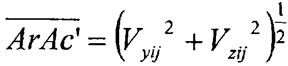
となり、接触角βijは、
(数10)
 となる。以上より玉16の弾性変形量δijは、
(数11)

となる。
(数8)
Vyij=(2f-1)Dasinγj+δyij
Vzij=(2f-1)Dacosγj+δzij
と表せる。これによりAr、Ac´間の距離は、
(数9)
となり、接触角βijは、
(数10)
(数11)
となる。
ここで、図7で示したキャリッジ12内の玉16が接触している部分をx軸方向に断面にした状態において、クラウニング、加工部分に入っている玉16の弾性変形量δijは、キャリッジ12側の転動面曲率中心のAc´がレール側転動面曲率中心Acから離れる形となっており、その分だけ少なくなる。それはちょうど玉径をそれに見合う形で小さくしたものと同等とみなせるため、その量をλxiとして上式中で差し引いている。
Hertzの接触論により導かれた転動体が玉の場合の弾性接近量を示す式を用いると、弾性変形量δijから転動体荷重Pijが下記の式によって求められる。
(数12)

ここで、Cbは非線形のばね定数(N/mm3/2)であり、下記の式で与えられる。
(数13)

ここで、Eは縦弾性係数、1/mはポアソン比、2K/πμはHertz係数、Σρは主曲率和である。
(数12)
ここで、Cbは非線形のばね定数(N/mm3/2)であり、下記の式で与えられる。
(数13)
ここで、Eは縦弾性係数、1/mはポアソン比、2K/πμはHertz係数、Σρは主曲率和である。
以上により、キャリッジ12の変位5成分α1~α5を用いて、キャリッジ12内のすべての玉16について、接触角βij、弾性変形量δij、転動体荷重Pijを式で表すことができたことになる。
なお、上記においては、わかり易くするために、キャリッジ12を剛体として考えた剛体モデル負荷分布理論を使用している。この剛体モデル負荷分布理論を拡張し、キャリッジ12の袖部12-2の変形を加味すべく梁理論を適用したキャリッジ梁モデル負荷分布理論を使用することもできる。さらに、キャリッジ12やレール11をFEMモデルとしたキャリッジ・レールFEMモデル負荷分布理論を使用することもできる。
<荷重(外力5成分)の算出>
あとは、上記の式を使って外力としての5成分、すなわちラジアル荷重Fy、ピッチングモーメントMa、ローリングモーメントMc、水平荷重Fz、ヨーイングモーメントMbに関するつり合い条件式をたてればよい。
(数14)
ラジアル荷重Fyに関して、

(数15)
ピッチングモーメントMaに関して、

(数16)
ローリングモーメントMcに関して、

ここで、ωijは、モーメントの腕の長さを表し、次式で与えられる。zr、yrは、点Arの座標である。

(数17)
水平荷重Fzに関して、
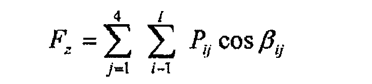
(数18)
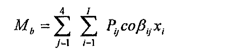 ヨーイングモーメントMbに関して、
以上の式からキャリッジ12に働く荷重(外力5成分)を算出することができる。
あとは、上記の式を使って外力としての5成分、すなわちラジアル荷重Fy、ピッチングモーメントMa、ローリングモーメントMc、水平荷重Fz、ヨーイングモーメントMbに関するつり合い条件式をたてればよい。
(数14)
ラジアル荷重Fyに関して、
(数15)
ピッチングモーメントMaに関して、
(数16)
ローリングモーメントMcに関して、
ここで、ωijは、モーメントの腕の長さを表し、次式で与えられる。zr、yrは、点Arの座標である。
(数17)
水平荷重Fzに関して、
(数18)
以上の式からキャリッジ12に働く荷重(外力5成分)を算出することができる。
<S103>
次に、ステップS103の詳細について説明する。コンピュータ6は、キャリッジ12が移動中であるか否かの判定を行う。キャリッジ12が移動中であるか否かは、リニアエンコーダ4が検出するキャリッジ12の位置情報を基に判定することができる。コンピュータ6は、例えば、リニアエンコーダ4が検出するキャリッジ12の位置情報が時系列で変化していればキャリッジ12が移動中と判定し、位置情報が時系列で変化していなければキャリッジ12が停止中と判定する。
次に、ステップS103の詳細について説明する。コンピュータ6は、キャリッジ12が移動中であるか否かの判定を行う。キャリッジ12が移動中であるか否かは、リニアエンコーダ4が検出するキャリッジ12の位置情報を基に判定することができる。コンピュータ6は、例えば、リニアエンコーダ4が検出するキャリッジ12の位置情報が時系列で変化していればキャリッジ12が移動中と判定し、位置情報が時系列で変化していなければキャリッジ12が停止中と判定する。
<S104>
次に、ステップS104の詳細について説明する。コンピュータ6は、データロガー5に記録されているキャリッジ12の変位量及び位置情報を基に、ウェービングの頂点の検出を行う。
次に、ステップS104の詳細について説明する。コンピュータ6は、データロガー5に記録されているキャリッジ12の変位量及び位置情報を基に、ウェービングの頂点の検出を行う。
ウェービングは、レール11の転動面11a及びキャリッジ本体13の転動面13aと玉16との間に生ずる周期的な相対位置のずれに起因するキャリッジ12の姿勢変化や振動(脈動)である。図10は、キャリッジ12がレール11を移動する際の玉16の動きを示した図である。キャリッジ12には複数の玉16が備わるが、これら複数の玉16のうちキャリッジ12を支持する玉16は、レール11の転動面11aとキャリッジ本体13の転動面13aとの間に挟まっている玉16(図10において斜線のハッチングが付されている玉16)である。そして、図10(A)と図10(B)とを見比べると判るように、レール11の転動面11aとキャリッジ本体13の転動面13aとの間に挟まっている玉16の数は、レール11に対するキャリッジ12の相対移動に伴って増減を繰り返す。この繰り返しの周期は、キャリッジ12がレール11に対し隣接する玉16同士のピッチと同じ量だけ移動する周期に一致する。よって、ウェービングの頂点は、センサ2a~2d,3a~3dによって検出された変位の波形のうち、キャリッジ12がレール11を移動する際に転がる玉16と転動面11a,13aとの間の相対位置のずれの周期に一致する波の頂点ということになる。
そこで、コンピュータ6は、ウェービングの頂点の検出にあたって、まず、変位5成分のそれぞれについて、リニアエンコーダ4から得られるキャリッジ12のレール11上の位置と、各センサ2a~2d,3a~3dから得られる変位量との関係を表したデータを解析する。そして、コンピュータ6は、キャリッジ12の位置と変位量との関係を表したデータの中から、ウェービングを表すデータの有無を判定する。ウェービングを表すデータの有無は、例えば、横軸をキャリッジ12のレール11上の位置とし、縦軸をキャリッジ12の変位量としたグラフの波形をイメージした場合に、玉16のピッチと略同一周期で現れるピークがあればウェービングが有ると判定され、玉16のピッチと略同一周期で現れるピークが存在しなければウェービングが無いと判定される。
図11は、リニアエンコーダ4によって検出されるキャリッジ12のレール11上の位置を横軸とし、センサ2a~2d,3a~3dによって検出される変位を縦軸としたグラフである。キャリッジ12には8つのセンサ2a~2d,3a~3dが備わっており、また、キャリッジ12はレール11を往復するため、キャリッジ12の位置と変位との関係を示す線は、本来、複数存在する。しかし、理解を容易にするため、図11のグラフでは、キャリッジ12の位置と変位との関係を1本の折れ線で示している。図11のグラフを見ると判るように、キャリッジ12の変位には、比較的緩慢な変位と比較的細かな変位の2種類の振動成分があることが判る。このうち、前者の比較的緩慢な変位は、例えばレール11の転動面11aの精度等に起因するウェービング以外の振動成分と考えられる。一方、後者の比較的細かな変位は、ウェービングに起因する振動成分であり、キャリッジ12がレール11を移動している際に発生する変位である。図11のグラフに示される比較的細かな変位の各頂点の横軸の間隔は、概ねボール16のピッチに一致する。
コンピュータ6は、図11のグラフに表されるような、キャリッジ12のレール11上の位置と変位量との関係を表したデータを基に、玉16のピッチと略同一周期で現れる細かなウェービングの振動成分を検出し、当該振動成分の波形の頂点の検出を行う。なお、コンピュータ6は、複数あるセンサ2a~2d,3a~3dのうち何れか1つ以上のセンサによって検出される変位のデータからウェービングが検出されれば、当該ウェービングの波形の頂点を検出する。
<S105>
コンピュータ6は、ステップS104でウェービングの波形の頂点を検出すると、ステップS102で算出された荷重を基に、キャリッジ12の転動面13aに発生する最大せん断応力(本願でいう「移動時応力」の一例である)を計算する。本実施形態では転動面13aの局部的な疲労による寿命を把握するため、コンピュータ6は、転動面13aに発生する最大せん断応力の計算を、転動面13aを軌道の方向沿いに区分けした仮想の区間毎に行う。
コンピュータ6は、ステップS104でウェービングの波形の頂点を検出すると、ステップS102で算出された荷重を基に、キャリッジ12の転動面13aに発生する最大せん断応力(本願でいう「移動時応力」の一例である)を計算する。本実施形態では転動面13aの局部的な疲労による寿命を把握するため、コンピュータ6は、転動面13aに発生する最大せん断応力の計算を、転動面13aを軌道の方向沿いに区分けした仮想の区間毎に行う。
図12は、転動面13aを区分けする仮想の区間の一例を示した図である。本実施形態では理解を容易にするため、転動面13aを有効玉数で分割した仮想の区間毎に最大せん断応力を計算する場合について説明する。このように区分けされた転動面13aの各区間に発生するせん断応力は、Hertzの弾性接触論に従い、ステップS102の説明で示した転動体荷重Pij、及び、球体と平面との接触部分に生ずる歪の解析モデルを用いて予め作成した式に従って算出することができる。
次に、コンピュータ6は、算出した各区間の最大せん断応力を基に、最大せん断応力の発生回数を応力の大きさ毎にカウントする。図13は、キャリッジ12が移動している時に転動面13aで繰り返し発生する最大せん断応力のカウント値の一例を示した図である。コンピュータ6は、例えば、図13に示すように、応力の大きさを50MPa毎に段階的に区分し、算出した最大せん断応力に該当する区分のカウンタ値を1ウェービング毎に、換言すると、図11に示したウェービングの波形において頂点が発生するタイミング毎に、1ずつ加算する。よって、カウンタ値は、キャリッジ12の積算移動距離に比例して増加する。転動面13aを疲労させる応力の発生回数が、応力の大きさ毎および区間毎に集計されることにより、例えば、転動面13aの特定の区間において局部的に繰り返される応力が発生している場合であっても、転動面13aの局部的な疲労を運動案内装置1の寿命診断に反映できる診断用の基礎データが得られる。
<S201>
コンピュータ6は、第1の処理フローが繰り返し実行されることで集計された集計結果を使い、寿命到達率を計算する。寿命到達率は、転動面13aの区間毎に算出される。そして、算出された全区間の寿命到達率の中から最も寿命到達率の高い値が運動案内装置1の寿命診断に採用される。寿命到達率は、例えば、線形累積損傷則を用いて算出される。図14は、材料のS-N曲線の一例を示した図である。線形累積損傷則は、材料の疲労において、物体が応力を繰り返し受ける場合に、疲労により損傷へ至るまでの寿命を予測するものであるため、キャリッジ12の移動中に発生する荷重振幅により繰り返される応力による材料の疲労の把握に有効である。線形累積損傷則に従えば、対象となる材料のS-N曲線における特定の繰返し応力に対する破断繰り返し数をLi、材料への実際の繰返し数をniとすると、寿命到達率Dは以下の式で与えられる。
(数19)

コンピュータ6は、第1の処理フローが繰り返し実行されることで集計された集計結果を使い、寿命到達率を計算する。寿命到達率は、転動面13aの区間毎に算出される。そして、算出された全区間の寿命到達率の中から最も寿命到達率の高い値が運動案内装置1の寿命診断に採用される。寿命到達率は、例えば、線形累積損傷則を用いて算出される。図14は、材料のS-N曲線の一例を示した図である。線形累積損傷則は、材料の疲労において、物体が応力を繰り返し受ける場合に、疲労により損傷へ至るまでの寿命を予測するものであるため、キャリッジ12の移動中に発生する荷重振幅により繰り返される応力による材料の疲労の把握に有効である。線形累積損傷則に従えば、対象となる材料のS-N曲線における特定の繰返し応力に対する破断繰り返し数をLi、材料への実際の繰返し数をniとすると、寿命到達率Dは以下の式で与えられる。
(数19)
<S202>
コンピュータ6は、ステップS201の処理を終えると、転動面13aの区間毎に算出された全区間の寿命到達率の中から最も寿命到達率の高い値を使い、キャリッジ12の残りの使用可能距離(期間)を計算する。使用可能距離(期間)は、例えば、線形累積損傷則に従えば、寿命到達率Dが1になった場合である。よって、使用可能距離DLifeは、リニアエンコーダ4の位置情報から得られるキャリッジ12の積算移動距離をDintとすると、以下の式で表すことができる。
(数20)
DLife=(1-D)/D*Dint
また、使用可能期間TLifeは、リニアエンコーダ4の使用開始時から寿命到達率D算出時までの経過時間をTintとすると、以下の式で表すことができる。
(数21)
TLife=(1-D)/D*Tint
コンピュータ6は、ステップS201の処理を終えると、転動面13aの区間毎に算出された全区間の寿命到達率の中から最も寿命到達率の高い値を使い、キャリッジ12の残りの使用可能距離(期間)を計算する。使用可能距離(期間)は、例えば、線形累積損傷則に従えば、寿命到達率Dが1になった場合である。よって、使用可能距離DLifeは、リニアエンコーダ4の位置情報から得られるキャリッジ12の積算移動距離をDintとすると、以下の式で表すことができる。
(数20)
DLife=(1-D)/D*Dint
また、使用可能期間TLifeは、リニアエンコーダ4の使用開始時から寿命到達率D算出時までの経過時間をTintとすると、以下の式で表すことができる。
(数21)
TLife=(1-D)/D*Tint
コンピュータ6が実行する上記ステップS101からS202までの各処理の詳細は以上の通りである。上記のコンピュータ6は、玉16がキャリッジ12の転動面13aに応力を繰り返し与えるウェービングの振動数を寿命診断に用いているため、ウェービングの振動数を用いずに行われる寿命診断よりも高精度な診断結果が得られる。また、上記のコンピュータ6は、ウェービングの振動数を、キャリッジ12の転動面13aに発生する応力の算出にも用いているセンサ2a,2b,3a,3bの変位情報でカウントするため、ウェービングの振動数をカウントするためのセンサ類を別途設ける場合よりも装置構成が複雑でない。また、上記のコンピュータ6は、キャリッジ12の転動面13aを軌道の方向沿いに区分けした仮想の区間毎に応力を算出しているため、転動面13a全体の応力を基にした寿命診断よりも高い診断結果を得ることができる。
1…運動案内装置、2a,2b,2c,2d,3a,3b,3c,3d…センサ、4…リニアエンコーダ、5…データロガー、6…コンピュータ、11…レール、12…キャリッジ、15a,15b…センサ取付け部材、15-1…水平部、15-2…袖部、16…玉
Claims (7)
- 軌道部材に複数の転動体を介して移動部材を相対移動可能に組み付けた運動案内装置の寿命診断装置であって、
前記軌道部材が形成する軌道に対する前記移動部材の変位量を基に、前記移動部材の転動面を前記軌道の方向沿いに区分けした仮想の区間毎に、前記移動部材が移動している際に各区間に発生する応力である移動時応力を算出する応力算出手段と、
前記移動部材が前記軌道沿いに移動する際のウェービングに伴い繰り返し発生する前記移動時応力の発生回数を、前記変位量を基に前記区間毎にカウントするカウント手段と、
前記移動時応力の大きさと前記移動時応力の発生回数とに基づく寿命到達率の算出を前記区間毎に行い、算出した前記各区間の寿命到達率を基に前記運動案内装置の寿命診断を行う診断手段と、を備える、
運動案内装置の寿命診断装置。 - 前記診断手段は、線形累積損傷則に従って前記寿命到達率の算出を行い、算出した前記各区間の寿命到達率を基に前記運動案内装置の寿命診断を行う、
請求項1に記載の運動案内装置の寿命診断装置。 - 前記診断手段は、前記移動時応力の大きさ毎の発生回数を前記区間毎に集計したテーブルのデータを基に、前記寿命到達率の算出を前記区間毎に行う、
請求項1または2に記載の運動案内装置の寿命診断装置。 - 前記移動部材は、前記軌道に対し直交する方向沿いに前記軌道部材の表面に対する距離を測定するセンサを有し、
前記変位量は、前記センサの出力に基づいて取得される、
請求項1から3の何れか一項に記載の運動案内装置の寿命診断装置。 - 軌道部材に複数の転動体を介して移動部材を相対移動可能に組み付けた運動案内装置の寿命診断方法であって、
前記軌道部材が形成する軌道に対する前記移動部材の変位量を基に、前記移動部材の転動面を前記軌道の方向沿いに区分けした仮想の区間毎に、前記移動部材が移動している際に各区間に発生する応力である移動時応力を算出し、
前記移動部材が前記軌道沿いに移動する際のウェービングに伴い繰り返し発生する前記移動時応力の発生回数を、前記変位量を基に前記区間毎にカウントし、
前記移動時応力の大きさと前記移動時応力の発生回数とに基づく寿命到達率の算出を前記区間毎に行い、算出した前記各区間の寿命到達率を基に前記運動案内装置の寿命診断を行う、
運動案内装置の寿命診断方法。 - 軌道部材に複数の転動体を介して移動部材を相対移動可能に組み付けた運動案内装置の寿命診断プログラムであって、
コンピュータに、
前記軌道部材が形成する軌道に対する前記移動部材の変位量を基に、前記移動部材の転動面を前記軌道の方向沿いに区分けした仮想の区間毎に、前記移動部材が移動している際に各区間に発生する応力である移動時応力を算出させ、
前記移動部材が前記軌道沿いに移動する際のウェービングに伴い繰り返し発生する前記移動時応力の発生回数を、前記変位量を基に前記区間毎にカウントさせ、
前記移動時応力の大きさと前記移動時応力の発生回数とに基づく寿命到達率の算出を前記区間毎に行い、算出した前記各区間の寿命到達率を基に前記運動案内装置の寿命診断を行わせる、
運動案内装置の寿命診断プログラム。 - 軌道部材に複数の転動体を介して移動部材を相対移動可能に組み付けた運動案内装置と、
前記軌道部材が形成する軌道に対する前記移動部材の変位量を基に、前記移動部材の転動面を前記軌道の方向沿いに区分けした仮想の区間毎に、前記移動部材が移動している際に各区間に発生する応力である移動時応力を算出する応力算出手段と、
前記移動部材が前記軌道沿いに移動する際のウェービングに伴い繰り返し発生する前記移動時応力の発生回数を、前記変位量を基に前記区間毎にカウントするカウント手段と、
前記移動時応力の大きさと前記移動時応力の発生回数とに基づく寿命到達率の算出を前記区間毎に行い、算出した前記各区間の寿命到達率を基に前記運動案内装置の寿命診断を行う診断手段と、を備える、
運動案内装置の寿命診断システム。
Priority Applications (4)
| Application Number | Priority Date | Filing Date | Title |
|---|---|---|---|
| CN201780081140.8A CN110121639B (zh) | 2016-12-28 | 2017-12-21 | 运动引导装置的寿命诊断装置、方法、非暂时性存储介质及系统 |
| KR1020197022041A KR102382244B1 (ko) | 2016-12-28 | 2017-12-21 | 운동 안내 장치의 수명 진단 장치, 방법, 프로그램 및 시스템 |
| US16/473,312 US11371909B2 (en) | 2016-12-28 | 2017-12-21 | Lifespan diagnosis device, method, non-transitory storage medium, and system for motion guidance device |
| DE112017006649.2T DE112017006649T5 (de) | 2016-12-28 | 2017-12-21 | Lebensdauerdiagnosevorrichtung, verfahren, programm und systemfür eine bevvegungsführungsvorrichtung |
Applications Claiming Priority (2)
| Application Number | Priority Date | Filing Date | Title |
|---|---|---|---|
| JP2016-256586 | 2016-12-28 | ||
| JP2016256586A JP6872900B2 (ja) | 2016-12-28 | 2016-12-28 | 運動案内装置の寿命診断装置、方法、プログラムおよびシステム |
Publications (1)
| Publication Number | Publication Date |
|---|---|
| WO2018123802A1 true WO2018123802A1 (ja) | 2018-07-05 |
Family
ID=62710405
Family Applications (1)
| Application Number | Title | Priority Date | Filing Date |
|---|---|---|---|
| PCT/JP2017/045915 Ceased WO2018123802A1 (ja) | 2016-12-28 | 2017-12-21 | 運動案内装置の寿命診断装置、方法、プログラムおよびシステム |
Country Status (7)
| Country | Link |
|---|---|
| US (1) | US11371909B2 (ja) |
| JP (1) | JP6872900B2 (ja) |
| KR (1) | KR102382244B1 (ja) |
| CN (1) | CN110121639B (ja) |
| DE (1) | DE112017006649T5 (ja) |
| TW (1) | TWI721238B (ja) |
| WO (1) | WO2018123802A1 (ja) |
Families Citing this family (9)
| Publication number | Priority date | Publication date | Assignee | Title |
|---|---|---|---|---|
| JP7224234B2 (ja) | 2019-04-25 | 2023-02-17 | Thk株式会社 | 異常診断システム、及び異常診断方法 |
| DE102019121395A1 (de) * | 2019-08-08 | 2021-02-11 | Ifm Electronic Gmbh | Positioniervorrichtung für Maschinenelemente oder Anlageteile |
| JP7409823B2 (ja) * | 2019-10-28 | 2024-01-09 | ファナック株式会社 | ロボットの寿命推定装置 |
| JP7298532B2 (ja) * | 2020-03-31 | 2023-06-27 | いすゞ自動車株式会社 | 推定装置及び、推定方法 |
| CN113704953A (zh) * | 2020-05-22 | 2021-11-26 | 沈机(上海)智能系统研发设计有限公司 | 寿命估算方法及其装置、介质、终端及伺服进给系统 |
| DE102020117883A1 (de) | 2020-07-07 | 2022-01-13 | Ifm Electronic Gmbh | Wälzführung mit einem Sensorelement |
| TWI752751B (zh) * | 2020-12-09 | 2022-01-11 | 上銀科技股份有限公司 | 用於偵測線性滑軌狀態的裝置和方法 |
| KR20230037141A (ko) | 2021-09-09 | 2023-03-16 | 주식회사 쥐엠피홀딩스 | 형상 기억 섬유를 이용한 얼굴 형태 변화를 기억하는 마스크 |
| DE102022116268A1 (de) * | 2022-06-29 | 2024-01-04 | Accuride International Gmbh | Vorrichtung und Verfahren zum Bereitstellen eines gekrümmten Verschiebewegs |
Citations (4)
| Publication number | Priority date | Publication date | Assignee | Title |
|---|---|---|---|---|
| JP2009074853A (ja) * | 2007-09-19 | 2009-04-09 | Ntn Corp | ころ軸受の寿命予測方法および寿命予測装置 |
| JP2011085532A (ja) * | 2009-10-16 | 2011-04-28 | Ntn Corp | ころ軸受の寿命予測方法および寿命予測装置 |
| JP2015218888A (ja) * | 2014-05-21 | 2015-12-07 | 日本精工株式会社 | 直動案内装置 |
| JP2015224728A (ja) * | 2014-05-28 | 2015-12-14 | 日本精工株式会社 | 直動案内装置 |
Family Cites Families (8)
| Publication number | Priority date | Publication date | Assignee | Title |
|---|---|---|---|---|
| DE1292696B (de) * | 1964-07-29 | 1969-04-17 | Kugelfischer G Schaefer & Co | Verfahren zur Erhoehung der Lebensdauer von Waelzpaarungen |
| JP2949794B2 (ja) * | 1990-06-25 | 1999-09-20 | 日本精工株式会社 | 転がり軸受 |
| US5952587A (en) * | 1998-08-06 | 1999-09-14 | The Torrington Company | Imbedded bearing life and load monitor |
| JP4435104B2 (ja) | 2006-03-29 | 2010-03-17 | 日本トムソン株式会社 | 直動案内ユニットおよび直動案内ユニットの荷重判別方法 |
| CN101586629A (zh) * | 2008-05-19 | 2009-11-25 | 瓦房店第一轧机轴承制造有限公司 | 一种高精度长寿命圆锥滚子滚道 |
| CN101957261B (zh) * | 2010-04-21 | 2012-05-16 | 中国人民解放军国防科学技术大学 | 滚动轴承多功能疲劳寿命试验台 |
| JP2014157047A (ja) * | 2013-02-15 | 2014-08-28 | Ntn Corp | 転がり軸受の寿命評価方法および寿命評価装置 |
| JP6619656B2 (ja) * | 2016-01-22 | 2019-12-11 | Thk株式会社 | 運動案内装置の荷重計測システム及び運動案内装置の寿命算出方法 |
-
2016
- 2016-12-28 JP JP2016256586A patent/JP6872900B2/ja active Active
-
2017
- 2017-12-21 KR KR1020197022041A patent/KR102382244B1/ko active Active
- 2017-12-21 CN CN201780081140.8A patent/CN110121639B/zh active Active
- 2017-12-21 DE DE112017006649.2T patent/DE112017006649T5/de active Pending
- 2017-12-21 WO PCT/JP2017/045915 patent/WO2018123802A1/ja not_active Ceased
- 2017-12-21 US US16/473,312 patent/US11371909B2/en active Active
- 2017-12-28 TW TW106146260A patent/TWI721238B/zh active
Patent Citations (4)
| Publication number | Priority date | Publication date | Assignee | Title |
|---|---|---|---|---|
| JP2009074853A (ja) * | 2007-09-19 | 2009-04-09 | Ntn Corp | ころ軸受の寿命予測方法および寿命予測装置 |
| JP2011085532A (ja) * | 2009-10-16 | 2011-04-28 | Ntn Corp | ころ軸受の寿命予測方法および寿命予測装置 |
| JP2015218888A (ja) * | 2014-05-21 | 2015-12-07 | 日本精工株式会社 | 直動案内装置 |
| JP2015224728A (ja) * | 2014-05-28 | 2015-12-14 | 日本精工株式会社 | 直動案内装置 |
Also Published As
| Publication number | Publication date |
|---|---|
| TWI721238B (zh) | 2021-03-11 |
| KR20190103243A (ko) | 2019-09-04 |
| US11371909B2 (en) | 2022-06-28 |
| DE112017006649T5 (de) | 2019-09-26 |
| JP2018109538A (ja) | 2018-07-12 |
| TW201831802A (zh) | 2018-09-01 |
| JP6872900B2 (ja) | 2021-05-19 |
| US20200103311A1 (en) | 2020-04-02 |
| CN110121639A (zh) | 2019-08-13 |
| KR102382244B1 (ko) | 2022-04-05 |
| CN110121639B (zh) | 2021-04-20 |
Similar Documents
| Publication | Publication Date | Title |
|---|---|---|
| KR102382244B1 (ko) | 운동 안내 장치의 수명 진단 장치, 방법, 프로그램 및 시스템 | |
| JP6619656B2 (ja) | 運動案内装置の荷重計測システム及び運動案内装置の寿命算出方法 | |
| KR102428628B1 (ko) | 가공 제어 시스템, 및 운동 안내 장치 | |
| US6591208B2 (en) | Correction method for a coordinate measuring apparatus | |
| Wu et al. | The effect of bending loads on the dynamic behaviors of a rolling guide | |
| JP2018119840A (ja) | 測定装置 | |
| KR102328346B1 (ko) | 관리 시스템 및 운동 안내 장치 | |
| KR20190108602A (ko) | 워크 반송 제어 시스템, 및 운동 안내 장치 | |
| Zhang et al. | Static and dynamic modeling, analysis, and experimental verification of a helical spring element with geometric nonlinearity theory |
Legal Events
| Date | Code | Title | Description |
|---|---|---|---|
| 121 | Ep: the epo has been informed by wipo that ep was designated in this application |
Ref document number: 17888735 Country of ref document: EP Kind code of ref document: A1 |
|
| ENP | Entry into the national phase |
Ref document number: 20197022041 Country of ref document: KR Kind code of ref document: A |
|
| 122 | Ep: pct application non-entry in european phase |
Ref document number: 17888735 Country of ref document: EP Kind code of ref document: A1 |