WO2018123640A1 - 撮像装置 - Google Patents
撮像装置 Download PDFInfo
- Publication number
- WO2018123640A1 WO2018123640A1 PCT/JP2017/045031 JP2017045031W WO2018123640A1 WO 2018123640 A1 WO2018123640 A1 WO 2018123640A1 JP 2017045031 W JP2017045031 W JP 2017045031W WO 2018123640 A1 WO2018123640 A1 WO 2018123640A1
- Authority
- WO
- WIPO (PCT)
- Prior art keywords
- dimensional position
- imaging
- unit
- straight
- position information
- Prior art date
- Legal status (The legal status is an assumption and is not a legal conclusion. Google has not performed a legal analysis and makes no representation as to the accuracy of the status listed.)
- Ceased
Links
Images



Classifications
-
- B—PERFORMING OPERATIONS; TRANSPORTING
- B60—VEHICLES IN GENERAL
- B60W—CONJOINT CONTROL OF VEHICLE SUB-UNITS OF DIFFERENT TYPE OR DIFFERENT FUNCTION; CONTROL SYSTEMS SPECIALLY ADAPTED FOR HYBRID VEHICLES; ROAD VEHICLE DRIVE CONTROL SYSTEMS FOR PURPOSES NOT RELATED TO THE CONTROL OF A PARTICULAR SUB-UNIT
- B60W40/00—Estimation or calculation of non-directly measurable driving parameters for road vehicle drive control systems not related to the control of a particular sub unit, e.g. by using mathematical models
- B60W40/10—Estimation or calculation of non-directly measurable driving parameters for road vehicle drive control systems not related to the control of a particular sub unit, e.g. by using mathematical models related to vehicle motion
-
- G—PHYSICS
- G06—COMPUTING OR CALCULATING; COUNTING
- G06T—IMAGE DATA PROCESSING OR GENERATION, IN GENERAL
- G06T7/00—Image analysis
-
- G—PHYSICS
- G06—COMPUTING OR CALCULATING; COUNTING
- G06T—IMAGE DATA PROCESSING OR GENERATION, IN GENERAL
- G06T7/00—Image analysis
- G06T7/50—Depth or shape recovery
- G06T7/55—Depth or shape recovery from multiple images
- G06T7/593—Depth or shape recovery from multiple images from stereo images
-
- G—PHYSICS
- G08—SIGNALLING
- G08G—TRAFFIC CONTROL SYSTEMS
- G08G1/00—Traffic control systems for road vehicles
- G08G1/16—Anti-collision systems
Definitions
- the present invention relates to an imaging device that is mounted on a moving body such as a vehicle and performs steering angle correction.
- the steering angle correction value on the side that receives the steering angle sensor value (for example, an imaging device for performing vehicle control such as an in-vehicle stereo camera).
- Patent Document 1 describes an imaging device that calculates a steering angle correction value by paying attention to a white line on an image captured by an in-vehicle camera.
- An object of the present invention is to realize an imaging device that can determine whether or not the host vehicle is traveling straight even when a moving body such as a vehicle is traveling on a road or the like that does not have a reference line such as a white line. is there.
- the present invention is configured as follows.
- the imaging apparatus of the present invention An imaging unit having a plurality of imaging elements for acquiring a plurality of images; A parallax image generation unit that generates a parallax image of an imaging target object that is a stationary object from the acquired plurality of images; Based on the parallax image generated by the parallax image generation unit, a three-dimensional position information extraction unit that acquires a plurality of time-series three-dimensional position information of the imaging object; A rectilinear determination unit that determines whether or not the mobile object travels straight based on the plurality of three-dimensional position information acquired by the three-dimensional position information extraction unit.
- an imaging device that can determine whether or not the host vehicle is traveling straight even when a moving body such as a vehicle is traveling on a road or the like that does not have a reference line such as a white line.
- the rudder angle correction value can be calculated without depending on the road condition.
- FIG. 1 is a schematic configuration diagram of an imaging apparatus that is an embodiment of the present invention, and is a diagram illustrating an example of an imaging apparatus mounted on a vehicle. It is a figure which shows the internal structure of the three-dimensional position information extraction part shown in FIG. BRIEF DESCRIPTION OF THE DRAWINGS
- FIG. 1 is a diagram for defining a road surface on which a host vehicle travels in order to describe an embodiment of the present invention.
- FIG. 4 is an overhead view showing an image obtained by looking down at FIG. 3. It is a schematic explanatory drawing of the straight-ahead determination logic based on the three-dimensional position locus of the stationary solid object in one Example of this invention. It is a processing flow when the straight traveling determination unit performs straight traveling determination of the host vehicle. It is a figure which shows an example of the flow which determines whether the plot result is a straight line in step 605 of FIG. It is a block diagram of an imaging device provided with a steering angle correction value calculating part in the structure of the imaging device shown
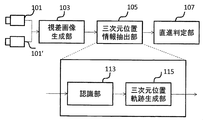
- FIG. 1 is a schematic configuration diagram of an imaging apparatus according to an embodiment of the present invention, which is an example of an imaging apparatus mounted on a vehicle.
- CMOS elements (imaging elements) 101 and 101 ′ constituting an imaging unit constitute a stereo camera and capture an input image (acquire an input image).
- the parallax image generation unit 103 generates parallax using the input images captured by the CMOS elements 101 and 101 ′.
- the three-dimensional position information extraction unit 105 extracts (acquires) characteristic three-dimensional position information using the parallax generated by the parallax image generation unit 103.
- the straight-ahead determination unit 107 performs a straight-ahead determination of the host vehicle based on the three-dimensional position information output from the three-dimensional position information extraction unit 105.
- FIG. 2 is a diagram showing an internal configuration of the three-dimensional position information extraction unit 105 shown in FIG.
- the three-dimensional position information extraction unit 105 includes a recognition unit 113 and a three-dimensional position locus generation unit 115.
- the recognition unit 113 recognizes an imaging target (for example, a stationary solid object or a road texture) using the parallax image generated by the parallax image generation unit 103, and outputs the result to the three-dimensional position locus generation unit 115.
- the three-dimensional position trajectory generation unit 115 plots the three-dimensional position of the target (for example, a stationary solid object or road texture) recognized by the recognition unit 113 for each frame of the captured image, and changes the time-series transition of the target three-dimensional position ( 3D position trajectory) is generated.
- the three-dimensional position trajectory generation unit 115 outputs the generated three-dimensional position trajectory to the straight travel determination unit 107.
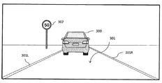
- FIG. 3 is a diagram for defining the condition of the road surface 301 in describing one embodiment of the present invention.
- the preceding vehicle 303 shown in FIG. 4
- the left and right white lines 301L and 301R the road surface texture (not shown)
- the sign (stationary solid object) 302 are present on the road surface 301.
- FIG. 3 is merely an example, and the present invention actually functions and can be implemented as long as one or more stationary solid objects or one or more detectable textures exist.
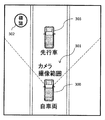
- FIG. 4 is an overhead view showing an image obtained by looking down at FIG.
- a range captured by the imaging units 101 and 101 ′ of the imaging apparatus is indicated by a dotted line.
- a preceding vehicle 303 exists in front of the host vehicle 300
- a sign 302 exists on the left side in front.
- Imaging units 101 and 101 ′ are arranged in front of the host vehicle 300.
- FIG. 5 is a schematic explanatory diagram of the straight-ahead determination logic based on the three-dimensional position locus of the stationary solid object in one embodiment of the present invention.
- FIG. 5A is a bird's-eye view of a state in which the host vehicle 300 has moved one frame from the state shown in FIG. 4, and FIG. is there.
- the three-dimensional position of the sign 302 is (x, y, z).
- the three-dimensional position where the marker 302 has moved in the (n + 1) frame, which is the next frame after the frame n, is (x ′, y ′, z ′).
- the three-dimensional position locus generation unit 115 determines the three-dimensional position of the sign 302 between a plurality of frames of n frames and n + 1 frames. Monitoring is performed, and the three-dimensional position locus 501 of the sign 302 is calculated.
- An arrow 500 in FIG. 5B indicates the traveling direction of the host vehicle 300.
- the straight traveling determination unit 107 determines from the locus generated by the three-dimensional position locus generation unit 115 that the three-dimensional position locus of the sign 302 has drawn a straight line, it is determined that the host vehicle 300 is traveling straight.
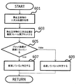
- FIG. 6 is a diagram illustrating an example of a processing flow when the straight traveling determination unit 107 performs a straight traveling determination of the host vehicle 300.
- the three-dimensional position coordinates of the stationary solid object are acquired (step 601).
- the three-dimensional position information acquired in the past of the stationary three-dimensional object 302 and the three-dimensional position information of the stationary three-dimensional object 302 extracted at the present time are plotted between a plurality of frames (step 603).
- step 605 it is determined whether or not the plot result is a straight line. If it is determined in step 605 that the vehicle is a straight line, it is determined that the host vehicle 300 is traveling straight (step 607). If it is determined in step 605 that the vehicle is not a straight line, it is determined that the host vehicle 300 is not traveling straight (609).
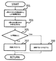
- FIG. 7 is a diagram showing an example of a flow for determining whether or not the plot result is a straight line in step 605 of FIG.
- n for example, three points
- three two-dimensional coordinates (x, y) are extracted from the three points (x, y, z) (steps). 701).
- the following equation (1) is used to solve the simultaneous equations of the unknowns a, b, and R to obtain the radius R (step 703).
- FIG. 8 is a configuration diagram of an imaging apparatus including a steering angle correction value calculation unit 809 in the configuration of the imaging apparatus of FIG.
- the steering angle correction value calculation unit 809 performs steering angle correction when the straight line determination unit 807 determines that the vehicle is traveling straight.
- the steering angle correction can be performed using a known method.
- the steering angle correction value calculation unit 809 is calculated not only when the straight line determination unit 807 determines that the vehicle is moving straight, but also when the straight angle determination unit 807 determines that the vehicle is not moving straight.
- the steering angle correction value can be calculated uniformly using the curvature and deviation.
- the imaging units 101 and 101 ′ continuously capture the stationary object 302 existing around the host vehicle 300, and the locus of the object 302 in the captured image.
- the vehicle 300 is a straight line
- the stationary object is the sign 302, but other stationary objects such as buildings and trees may be used.
- a stationary object can be automatically determined from a plurality of existing objects. For example, an object that is first determined as a stationary object from the obtained image may be used as the object.
- the distance at which the target is imaged by the image sensor for example, between 0.1 m and 300 m, can be determined to go straight.
- the stationary object existing in front of the host vehicle 300 is the target for straight-ahead determination, but it is also possible to target a stationary object in all directions centered on the host vehicle.
- a stationary object existing behind the host vehicle as a target for straight-ahead determination.
- an imaging unit having a plurality of imaging elements is disposed in the rear part of the host vehicle 300.
- the present invention is also possible to arrange a plurality of imaging units that image the periphery of the host vehicle 300. For example, it is possible to dispose an imaging unit in front of and behind the host vehicle 300 and use the captured stationary object as an object for straight ahead determination. Furthermore, in the above-described example, an example in which the present invention is applied to an imaging device mounted on a vehicle has been described. However, the present invention is not limited to a vehicle, and is a moving body that recognizes the outside world, steers, and moves. If present, the present invention can be applied.
- the present invention can also be applied to a baggage carrying robot that carries a baggage etc. to a target location. .
Landscapes
- Engineering & Computer Science (AREA)
- Physics & Mathematics (AREA)
- General Physics & Mathematics (AREA)
- Computer Vision & Pattern Recognition (AREA)
- Theoretical Computer Science (AREA)
- Mathematical Physics (AREA)
- Automation & Control Theory (AREA)
- Transportation (AREA)
- Mechanical Engineering (AREA)
- Image Analysis (AREA)
- Traffic Control Systems (AREA)
- Image Processing (AREA)
- Control Of Driving Devices And Active Controlling Of Vehicle (AREA)
- Studio Devices (AREA)
Abstract
本発明は、白線を初めとする基準直線が無い道路等を車両等の移動体が走行中であっても、自車両が直進しているか否を判定可能な撮像装置を実現する。本発明は、自車両300の周囲に存在する静止対象物302を撮像部101、101'が連続して撮像し、自車両300のボンネットの先端を原点とした座標を用いて、撮像した画像における対象物302の軌跡が、直線か否かにより、自車両300が、直進しているか否かを判定する。これによって、白線を初めとする基準直線が無い道路等を車両等の移動体が走行中であっても、自車両が直進しているか否を判定可能となる。
Description
本発明は、車両等の移動体に搭載され、舵角補正を行うための撮像装置に関する。
近年、自動運転を初めとする車両制御技術に注目が集まっている。正確な車両制御を行う為にはリアルタイムに更新される多数の車載センサ出力値が必要であり、中でも自車挙動を計算する際に利用される操舵角センサ値は精度が求められる。
しかし、操舵角センサ値のゼロ点には経年劣化によりオフセットが加算される。このため、精度良く、遅れの無い操舵角値を得る為には、操舵角補正値計算を行う事が肝要である。
また、コスト低減の為、操舵角センサ値を受け取る側(例えば、車載ステレオカメラ等の車両制御を行うための撮像装置)で操舵角補正値計算を行う事が望ましい。
このため、従来から、操舵角補正値計算を行う様々な技術や、撮像装置が提案されてきた。
例えば、特許文献1には、車載カメラで撮像した画像上の白線に着目し、操舵角補正値計算を行う撮像装置が記載されている。
しかしながら、特許文献1等に記載された従来技術では、白線を初めとした画像上の基準線が撮像されていないと目標走行ラインが設定出来ず、舵角補正値計算を行う事が出来ない。
白線等の基準線がない道路であっても、舵角補正値計算を行うことが可能となれば、車両制御の精度を向上することができる。
このため、その実現化が望まれている。
本発明の目的は、白線を初めとする基準直線が無い道路等を車両等の移動体が走行中であっても、自車両が直進しているか否を判定可能な撮像装置を実現することである。
上記目的を達成するため、本発明は次のように構成される。
本発明の撮像装置は、
複数の画像を取得する複数の撮像素子を有する撮像部と、
取得された上記複数の画像から、静止物である撮像対象物の視差画像を生成する視差画像生成部と、
上記視差画像生成部により生成された上記視差画像に基づいて、上記撮像対象物の、時系列の複数の三次元位置情報を取得する三次元位置情報抽出部と、
上記三次元位置情報抽出部により取得された上記複数の三次元位置情報に基づいて、移動体の直進判定をする直進判定部と、を備える。
複数の画像を取得する複数の撮像素子を有する撮像部と、
取得された上記複数の画像から、静止物である撮像対象物の視差画像を生成する視差画像生成部と、
上記視差画像生成部により生成された上記視差画像に基づいて、上記撮像対象物の、時系列の複数の三次元位置情報を取得する三次元位置情報抽出部と、
上記三次元位置情報抽出部により取得された上記複数の三次元位置情報に基づいて、移動体の直進判定をする直進判定部と、を備える。
本発明によれば、白線を初めとする基準直線が無い道路等を車両等の移動体が走行中であっても、自車両が直進しているか否を判定可能な撮像装置を実現することができ、道路状況に寄らない舵角補正値計算をすることができる。
前述した以外の課題、構成、効果は以下の実施形態の説明にて述べる。
本発明の実施形態について、添付図面を参照して説明する。
図1は、本発明の一実施例である撮像装置の概略構成図であり、車両に搭載される撮像装置の例である。
図1において、撮像部を構成する複数のCMOS素子(撮像素子)101および101’は、ステレオカメラを構成し、入力画像を撮像する(入力画像を取得する)。視差画像生成部103は、CMOS素子101および101’が撮像した入力画像を用いて、視差を生成する。
三次元位置情報抽出部105は、視差画像生成部103が生成する視差を用いて、特徴となる三次元位置情報を抽出する(取得する)。直進判定部107は、三次元位置情報抽出部105が出力した三次元位置情報を基に、自車の直進判定を行う。
図2は、図1に示した三次元位置情報抽出部105の内部構成を示した図である。
図2において、三次元位置情報抽出部105は、認識部113と、三次元位置軌跡生成部115とを備える。
認識部113は、視差画像生成部103が生成した視差画像を用いて、撮像対象物(例えば静止立体物や路面テクスチャ)の認識を行い、その結果を三次元位置軌跡生成部115に出力する。三次元位置軌跡生成部115は、認識部113が認識した対象(例えば静止立体物または路面テクスチャ)の三次元位置を、撮影画像のフレーム毎にプロットし、対象の三次元位置の時系列推移(三次元位置軌跡)を生成する。
そして、三次元位置軌跡生成部115は、生成した三次元位置軌跡を直進判定部107に出力する。
図3は、本発明の一実施例を説明する上で、路面301の状況を定義するための図である。今回説明する一実施例は、先行車303(図4に示す)、左右の白線301L、301R、路面テクスチャ(図示は省略図する)、標識(静止立体物)302が、路面301上に存在していると仮定する。
なお、図3に示した例は一例であり、実際には静止立体物、または検出可能なテクスチャが1つ以上存在していれば本発明は機能し、実施可能である。
図4は、図3を俯瞰したイメージを示す俯瞰図である。図4において、撮像装置の撮像部101、101’が撮影する範囲を点線で記載している。図4に示した例では、自車両300の前方に先行車303が存在し、前方左側に標識302が存在している。自車両300の前方部に撮像部101、101’が配置されている。
図5は、本発明の一実施例における静止立体物の三次元位置軌跡に基づく直進判定ロジックの概略説明図である。図5の(a)は、自車両300が図4に示した状態から1フレーム間に移動した状態の俯瞰図であり、図5の(b)は、直進判定をイメージ的に説明する図である。
図3、図4、図5において、撮像画像の現フレームをnとした時、同フレームnで標識302を静止立体物として検出した場合を考える。
自車両300の長さ方向中心線上かつ自車両300の前方部であるボンネットの先端を原点Oとしたとき、標識302の三次元位置を(x,y,z)とする。
そして、フレームnの次のフレームであるn+1フレームで、同標識302が移動した三次元位置を(x’,y’,z’)とする。
三次元位置情報抽出部105の認識部113が認識した情報に基づいて、三次元位置軌跡生成部115は、nフレームとn+1フレームとの複数のフレームの間に渡って標識302の三次元位置を監視し、標識302の三次元位置軌跡501を算出する。図5の(b)の矢印500は自車両300の進行方向を示している。
三次元位置軌跡生成部115が生成した軌跡から、直進判定部107が、標識302の三次元位置軌跡が直線を描いていたと判定した場合は、自車両300が直進していると判断する。
以上の手法を取る事で、白線を初めとする基準直線が無い路面でも、対象(例えば静止立体物(一例として標識302)や路面テクスチャさえあれば直進判定する事が可能となる。
図6は、直進判定部107が、自車両300の直進判定を行う際の処理フローの一例を示す図である。
図6において、静止立体物(標識302)の三次元位置座標を取得する(ステップ601)。次に、静止立体物302の過去に取得された三次元位置情報と現時点で抽出された静止立体物302の三次元位置情報とを複数フレーム間プロットする(ステップ603)。
そして、プロット結果が直線になっているかどうか判定する(ステップ605)。このステップ605で、直線になっていると判定した場合は、自車両300が直進していると判定する(ステップ607)。ステップ605で、直線になっていないと判定した場合は、自車両300が直進していないと判定する(609)。
図7は、図6のステップ605において、プロット結果が直線になっているかどうか判定するフローの一例を示す図である。
図7において、n個(例えば3点)の三次元位置座標が得られた場合、3点の座標(x,y,z)から3点の二次元座標(x,y)を抽出する(ステップ701)。
抽出した3点の二次元時座標を用いて、例えば、次式(1)を用いて、未知数a、b、Rの連立方程式を解き、半径Rを求める(ステップ703)。
(x-a)2+(y-b)2=R2 ・・・(1)
上記式(1)で求めた半径Rが閾値(例えばR=1000m)以上か否かを判断する(ステップ705)。半径Rが閾値(例えばR=1000m)以上であれば、直線であると判定して処理を終える(ステップ707)。
上記式(1)で求めた半径Rが閾値(例えばR=1000m)以上か否かを判断する(ステップ705)。半径Rが閾値(例えばR=1000m)以上であれば、直線であると判定して処理を終える(ステップ707)。
そして、半径Rが閾値未満であれば直線では無いと判定し、処理を終える(ステップ709)。
図8は、図1の撮像装置の構成に舵角補正値演算部809を備える撮像装置の構成図である。
舵角補正値演算部809は、直線判定部807により直進していると判定された場合に舵角補正を行う。舵角補正は、公知の手法を用いて行うことができる。
舵角補正値演算部809は、直線判定部807により、直進していると判定された場合のみならず、直進していないと判定された場合であっても、直進判定部807で求めたRの曲率や偏差を用いて、一律に舵角補正値を演算するように構成することもできる。
以上のように、本発明の一実施例によれば、自車両300の周囲に存在する静止対象物302を撮像部101、101’が連続して撮像し、撮像した画像における対象物302の軌跡が、直線か否かにより、自車両300が、直進しているか否かを判定するように構成したので、白線を初めとする基準直線が無い道路等を車両等の移動体が走行中であっても、自車両が直進しているか否を判定可能な撮像装置を実現することができる。
なお、上述した例は、静止対象物を標識302としたが、建造物、木々等の他の静止物であってもよい。静止物は複数存在する物のうちから自動的に決定することができる。例えば、得られた画像から最初に静止物と判定したものを対象物としてもよい。
また、複数の静止立体物を対象に、それぞれの軌跡から自車両300の直進判定をしてもよい。
また、撮像素子に対象が撮像される距離、例えば0.1m~300mの間であれば、直進判定可能である。
また、上述した例は、自車両300の前方に存在する静止物を直進判定の対象物としたが、自車両を中心とした全方位の静止物を対象とする事も可能である。例えば、自車両の後方に存在する静止物を直進判定の対象物とすることも可能である。この場合は、自車両300の後方部に、複数の撮像素子を有する撮像部が配置されていることが必要である。
また、自車両300の周辺を撮像する複数の撮像部を配置する事も可能である。例えば、自車両300の前方及び後方に撮像部を配置し、撮像した静止物を直進判定の対象物とすることも可能である。
さらに、上述した例においては、本発明を車両に搭載する撮像装置に適用した場合の例を説明したが、車両に限らず、移動体であり、外界を認識して操舵し、移動するものであれば、本発明を適用することができる。
さらに、上述した例においては、本発明を車両に搭載する撮像装置に適用した場合の例を説明したが、車両に限らず、移動体であり、外界を認識して操舵し、移動するものであれば、本発明を適用することができる。
例えば、目的箇所に、荷物等を運搬する荷物運搬用ロボット等にも本発明は適用可能であり、その場合は、白線等の基準線が存在しない場合でも、走行中に直進判定が可能である。
101、101’・・・撮像部、
103・・・視差画像生成部、
105・・・三次元位置情報抽出部、
107・・・直進判定部、
113・・・認識部、
115・・・三次元位置軌跡生成部、
300・・・自車両、
301・・・路面、
302・・・標識(静止対象物)、
303・・・先行車、
301L、301R・・・白線、
500・・・自車進行方向、
501・・・静止対象物の軌跡、
809・・・舵角補正値演算部
103・・・視差画像生成部、
105・・・三次元位置情報抽出部、
107・・・直進判定部、
113・・・認識部、
115・・・三次元位置軌跡生成部、
300・・・自車両、
301・・・路面、
302・・・標識(静止対象物)、
303・・・先行車、
301L、301R・・・白線、
500・・・自車進行方向、
501・・・静止対象物の軌跡、
809・・・舵角補正値演算部
Claims (7)
- 複数の画像を取得する複数の撮像素子を有する撮像部と、
取得された上記複数の画像から、静止物である撮像対象物の視差画像を生成する視差画像生成部と、
上記視差画像生成部により生成された上記視差画像に基づいて、上記撮像対象物の、時系列の複数の三次元位置情報を取得する三次元位置情報抽出部と、
上記三次元位置情報抽出部により取得された上記複数の三次元位置情報に基づいて、移動体の直進判定をする直進判定部と、
を備えることを特徴とする撮像装置。 - 請求項1に記載の撮像装置において、
上記三次元位置情報抽出部は、
上記視差画像生成部により生成された上記視差画像に基づいて、上記撮像対象物を認識する認識部と、
上記認識部により、認識された上記撮像対象物の三次元位置情報を取得し、過去に取得された三次元位置情報と現時点で抽出された三次元位置情報とから上記撮像対象物の三次元位置軌跡を生成する三次元位置軌跡生成部とを有し、
上記直進判定部は、上記三次元位置軌跡生成部が生成した三次元位置軌跡が所定の曲率以上であるか否かに基づいて、直進判定をすることを特徴とする撮像装置。 - 請求項1に記載の撮像装置において、
上記三次元位置軌跡生成部が生成した三次元位置軌跡に基づいて、上記移動体の舵角補正を行う舵角補正値演算部を有することを特徴とする撮像装置。 - 請求項3に記載の撮像装置において、
上記直進判定部は上記直進判定に用いた情報を上記舵角補正値演算部に出力し、上記舵角補正値演算部は、上記直進判定部から出力された上記情報に基づいて舵角補正を行うことを特徴とする撮像装置。 - 請求項2に記載の撮像装置において、
上記三次元位置情報抽出部は、上記移動体の3点間の移動軌跡を表す二次方程式を算出し、上記直進判定部は、上記三次元位置情報抽出部が算出した上記二次方程式から算出される曲率が、予め定めた曲率より以上か否かにより、上記移動体の直進判定をすることを特徴とする撮像装置。 - 請求項1に記載の撮像装置において、
上記撮像部は、上記移動体の前方部に配置されていることを特徴とする撮像装置。 - 請求項1に記載の撮像装置において、
上記撮像部は、上記移動体の後方部に配置されていることを特徴とする撮像装置。
Priority Applications (2)
| Application Number | Priority Date | Filing Date | Title |
|---|---|---|---|
| JP2018559042A JP6841553B2 (ja) | 2016-12-26 | 2017-12-15 | 撮像装置 |
| CN201780071990.XA CN110088803B (zh) | 2016-12-26 | 2017-12-15 | 摄像装置 |
Applications Claiming Priority (2)
| Application Number | Priority Date | Filing Date | Title |
|---|---|---|---|
| JP2016251458 | 2016-12-26 | ||
| JP2016-251458 | 2016-12-26 |
Publications (1)
| Publication Number | Publication Date |
|---|---|
| WO2018123640A1 true WO2018123640A1 (ja) | 2018-07-05 |
Family
ID=62708164
Family Applications (1)
| Application Number | Title | Priority Date | Filing Date |
|---|---|---|---|
| PCT/JP2017/045031 Ceased WO2018123640A1 (ja) | 2016-12-26 | 2017-12-15 | 撮像装置 |
Country Status (3)
| Country | Link |
|---|---|
| JP (1) | JP6841553B2 (ja) |
| CN (1) | CN110088803B (ja) |
| WO (1) | WO2018123640A1 (ja) |
Families Citing this family (2)
| Publication number | Priority date | Publication date | Assignee | Title |
|---|---|---|---|---|
| CN111976717B (zh) * | 2019-11-29 | 2022-07-08 | 长城汽车股份有限公司 | 一种智能泊车方法和装置 |
| EP4254382A4 (en) * | 2020-11-27 | 2023-10-04 | Nissan Motor Co., Ltd. | VEHICLE ASSISTANCE METHOD AND VEHICLE ASSISTANCE DEVICE |
Citations (2)
| Publication number | Priority date | Publication date | Assignee | Title |
|---|---|---|---|---|
| JP2006199242A (ja) * | 2005-01-24 | 2006-08-03 | Toyota Motor Corp | 車両の挙動制御装置 |
| JP2014046710A (ja) * | 2012-08-29 | 2014-03-17 | Isuzu Motors Ltd | 操舵角センサの中立点補正装置及び中立点補正方法 |
Family Cites Families (5)
| Publication number | Priority date | Publication date | Assignee | Title |
|---|---|---|---|---|
| JPH10222665A (ja) * | 1997-01-31 | 1998-08-21 | Fujitsu Ten Ltd | 画像認識装置 |
| JP5074365B2 (ja) * | 2008-11-28 | 2012-11-14 | 日立オートモティブシステムズ株式会社 | カメラ装置 |
| US9168953B2 (en) * | 2011-11-08 | 2015-10-27 | Toyota Jidosha Kabushiki Kaisha | Vehicle travel track control device |
| WO2013157301A1 (ja) * | 2012-04-16 | 2013-10-24 | 日産自動車株式会社 | 立体物検出装置及び立体物検出方法 |
| JP6328369B2 (ja) * | 2012-11-27 | 2018-05-23 | クラリオン株式会社 | 車載用制御装置 |
-
2017
- 2017-12-15 WO PCT/JP2017/045031 patent/WO2018123640A1/ja not_active Ceased
- 2017-12-15 JP JP2018559042A patent/JP6841553B2/ja active Active
- 2017-12-15 CN CN201780071990.XA patent/CN110088803B/zh active Active
Patent Citations (2)
| Publication number | Priority date | Publication date | Assignee | Title |
|---|---|---|---|---|
| JP2006199242A (ja) * | 2005-01-24 | 2006-08-03 | Toyota Motor Corp | 車両の挙動制御装置 |
| JP2014046710A (ja) * | 2012-08-29 | 2014-03-17 | Isuzu Motors Ltd | 操舵角センサの中立点補正装置及び中立点補正方法 |
Non-Patent Citations (1)
| Title |
|---|
| SEKI, AKIHITO ET AL.: "Ego-motion Estimation by Tracking Road-regions Extracted Using Stereo Images", TRANSACTIONS OF INFORMATION PROCESSING SOCIETY OF JAPAN, vol. 47, 15 March 2006 (2006-03-15), pages 90 - 99, ISSN: 0387-5806 * |
Also Published As
| Publication number | Publication date |
|---|---|
| JP6841553B2 (ja) | 2021-03-10 |
| JPWO2018123640A1 (ja) | 2019-10-31 |
| CN110088803B (zh) | 2023-05-12 |
| CN110088803A (zh) | 2019-08-02 |
Similar Documents
| Publication | Publication Date | Title |
|---|---|---|
| US11657604B2 (en) | Systems and methods for estimating future paths | |
| CN106335509B (zh) | 车辆的驾驶辅助装置 | |
| CN107209998B (zh) | 车道线识别装置以及车道线识别方法 | |
| JP2020067698A (ja) | 区画線検出装置及び区画線検出方法 | |
| KR102056147B1 (ko) | 자율주행차량을 위한 거리 데이터와 3차원 스캔 데이터의 정합 방법 및 그 장치 | |
| CN107306338A (zh) | 用于对象检测和跟踪的全景摄像机系统 | |
| CN105984470B (zh) | 图像处理装置和图像处理方法 | |
| CN105719311A (zh) | 用于检测目标的车辆系统及其操作方法 | |
| CN105022986A (zh) | 移动体控制装置以及对象物检测装置 | |
| JP2008310440A (ja) | 歩行者検出装置 | |
| Phan et al. | Sensor fusion of camera and 2d lidar for self-driving automobile in obstacle avoidance scenarios | |
| Zhang et al. | Real-time obstacle detection based on stereo vision for automotive applications | |
| JP6939198B2 (ja) | 物体検出方法及び物体検出装置 | |
| JP2000293693A (ja) | 障害物検出方法および装置 | |
| CN111753632B (zh) | 驾驶辅助装置 | |
| JP6174884B2 (ja) | 車外環境認識装置および車外環境認識方法 | |
| US20150379372A1 (en) | Object recognition apparatus | |
| JPWO2018123640A1 (ja) | 撮像装置 | |
| JP2015067030A (ja) | 運転支援装置 | |
| JP2020076714A (ja) | 位置姿勢推定装置 | |
| JP5345999B2 (ja) | レーンマーク認識装置 | |
| JP6057660B2 (ja) | 車線監視システム及び車線監視方法 | |
| JP2019020289A (ja) | 移動ベクトル算出方法及び移動ベクトル算出装置 | |
| CN113836964A (zh) | 车道线角点检测方法及装置 | |
| CN112400094B (zh) | 物体探测装置 |
Legal Events
| Date | Code | Title | Description |
|---|---|---|---|
| 121 | Ep: the epo has been informed by wipo that ep was designated in this application |
Ref document number: 17887474 Country of ref document: EP Kind code of ref document: A1 |
|
| ENP | Entry into the national phase |
Ref document number: 2018559042 Country of ref document: JP Kind code of ref document: A |
|
| NENP | Non-entry into the national phase |
Ref country code: DE |
|
| 122 | Ep: pct application non-entry in european phase |
Ref document number: 17887474 Country of ref document: EP Kind code of ref document: A1 |