WO2018123383A1 - 集塵フィルタ及び空気清浄機 - Google Patents
集塵フィルタ及び空気清浄機 Download PDFInfo
- Publication number
- WO2018123383A1 WO2018123383A1 PCT/JP2017/042307 JP2017042307W WO2018123383A1 WO 2018123383 A1 WO2018123383 A1 WO 2018123383A1 JP 2017042307 W JP2017042307 W JP 2017042307W WO 2018123383 A1 WO2018123383 A1 WO 2018123383A1
- Authority
- WO
- WIPO (PCT)
- Prior art keywords
- dust collection
- fragrance
- collection filter
- air
- electrode
- Prior art date
- Legal status (The legal status is an assumption and is not a legal conclusion. Google has not performed a legal analysis and makes no representation as to the accuracy of the status listed.)
- Ceased
Links
Images








Classifications
-
- F—MECHANICAL ENGINEERING; LIGHTING; HEATING; WEAPONS; BLASTING
- F24—HEATING; RANGES; VENTILATING
- F24F—AIR-CONDITIONING; AIR-HUMIDIFICATION; VENTILATION; USE OF AIR CURRENTS FOR SCREENING
- F24F7/00—Ventilation
- F24F7/003—Ventilation in combination with air cleaning
-
- A—HUMAN NECESSITIES
- A61—MEDICAL OR VETERINARY SCIENCE; HYGIENE
- A61L—METHODS OR APPARATUS FOR STERILISING MATERIALS OR OBJECTS IN GENERAL; DISINFECTION, STERILISATION OR DEODORISATION OF AIR; CHEMICAL ASPECTS OF BANDAGES, DRESSINGS, ABSORBENT PADS OR SURGICAL ARTICLES; MATERIALS FOR BANDAGES, DRESSINGS, ABSORBENT PADS OR SURGICAL ARTICLES
- A61L9/00—Disinfection, sterilisation or deodorisation of air
- A61L9/015—Disinfection, sterilisation or deodorisation of air using gaseous or vaporous substances, e.g. ozone
- A61L9/04—Disinfection, sterilisation or deodorisation of air using gaseous or vaporous substances, e.g. ozone using substances evaporated in the air without heating
- A61L9/12—Apparatus, e.g. holders, therefor
-
- B—PERFORMING OPERATIONS; TRANSPORTING
- B01—PHYSICAL OR CHEMICAL PROCESSES OR APPARATUS IN GENERAL
- B01D—SEPARATION
- B01D46/00—Filters or filtering processes specially modified for separating dispersed particles from gases or vapours
- B01D46/10—Particle separators, e.g. dust precipitators, using filter plates, sheets or pads having plane surfaces
-
- B—PERFORMING OPERATIONS; TRANSPORTING
- B03—SEPARATION OF SOLID MATERIALS USING LIQUIDS OR USING PNEUMATIC TABLES OR JIGS; MAGNETIC OR ELECTROSTATIC SEPARATION OF SOLID MATERIALS FROM SOLID MATERIALS OR FLUIDS; SEPARATION BY HIGH-VOLTAGE ELECTRIC FIELDS
- B03C—MAGNETIC OR ELECTROSTATIC SEPARATION OF SOLID MATERIALS FROM SOLID MATERIALS OR FLUIDS; SEPARATION BY HIGH-VOLTAGE ELECTRIC FIELDS
- B03C3/00—Separating dispersed particles from gases or vapour, e.g. air, by electrostatic effect
- B03C3/02—Plant or installations having external electricity supply
-
- B—PERFORMING OPERATIONS; TRANSPORTING
- B03—SEPARATION OF SOLID MATERIALS USING LIQUIDS OR USING PNEUMATIC TABLES OR JIGS; MAGNETIC OR ELECTROSTATIC SEPARATION OF SOLID MATERIALS FROM SOLID MATERIALS OR FLUIDS; SEPARATION BY HIGH-VOLTAGE ELECTRIC FIELDS
- B03C—MAGNETIC OR ELECTROSTATIC SEPARATION OF SOLID MATERIALS FROM SOLID MATERIALS OR FLUIDS; SEPARATION BY HIGH-VOLTAGE ELECTRIC FIELDS
- B03C3/00—Separating dispersed particles from gases or vapour, e.g. air, by electrostatic effect
- B03C3/34—Constructional details or accessories or operation thereof
- B03C3/40—Electrode constructions
-
- B—PERFORMING OPERATIONS; TRANSPORTING
- B03—SEPARATION OF SOLID MATERIALS USING LIQUIDS OR USING PNEUMATIC TABLES OR JIGS; MAGNETIC OR ELECTROSTATIC SEPARATION OF SOLID MATERIALS FROM SOLID MATERIALS OR FLUIDS; SEPARATION BY HIGH-VOLTAGE ELECTRIC FIELDS
- B03C—MAGNETIC OR ELECTROSTATIC SEPARATION OF SOLID MATERIALS FROM SOLID MATERIALS OR FLUIDS; SEPARATION BY HIGH-VOLTAGE ELECTRIC FIELDS
- B03C3/00—Separating dispersed particles from gases or vapour, e.g. air, by electrostatic effect
- B03C3/34—Constructional details or accessories or operation thereof
- B03C3/40—Electrode constructions
- B03C3/41—Ionising-electrodes
-
- B—PERFORMING OPERATIONS; TRANSPORTING
- B03—SEPARATION OF SOLID MATERIALS USING LIQUIDS OR USING PNEUMATIC TABLES OR JIGS; MAGNETIC OR ELECTROSTATIC SEPARATION OF SOLID MATERIALS FROM SOLID MATERIALS OR FLUIDS; SEPARATION BY HIGH-VOLTAGE ELECTRIC FIELDS
- B03C—MAGNETIC OR ELECTROSTATIC SEPARATION OF SOLID MATERIALS FROM SOLID MATERIALS OR FLUIDS; SEPARATION BY HIGH-VOLTAGE ELECTRIC FIELDS
- B03C3/00—Separating dispersed particles from gases or vapour, e.g. air, by electrostatic effect
- B03C3/34—Constructional details or accessories or operation thereof
- B03C3/40—Electrode constructions
- B03C3/45—Collecting-electrodes
- B03C3/47—Collecting-electrodes flat, e.g. plates, discs, gratings
Definitions
- the present invention relates to a dust collecting filter and an air cleaner that emit fragrance.
- this type of air purifier is provided with a dust collecting filter in an air flow passage and an aroma portion for releasing a fragrance in the air flow passage, as described in Patent Document 1 and Patent Document 2, for example.
- a dust collecting filter in an air flow passage and an aroma portion for releasing a fragrance in the air flow passage
- the air cleaner sucks air from the inlet into the air flow passage, removes dust and the like in the air by the dust collecting filter interposed in the air flow passage, and then discharges the air from the passage outlet. Then, the fragrance released from the fragrance part is discharged to the outside together with the air in the air flow passage to relax the user's mind and body or to recover from fatigue.
- the above-described conventional air cleaner has the following problems.
- the conventional air purifier uses a specially manufactured aroma device and essential oil volatilization device as the fragrance part that emits a fragrance, and these devices are built into the air purifier.
- the structure becomes complicated and the manufacturing cost increases.
- the used air freshener and clogged dust collection filter must be replaced separately, and the replacement work is complicated.
- the present invention has been made in order to solve the above-described problems.
- a dust collection filter and an air cleaner having a simple structure and easy replacement of a fragrance and a dust collection filter used in a fragrance portion are provided.
- the purpose is to provide.
- the dust collection filter according to the first aspect of the present invention holds one or more planar bodies that adsorb dust in the air when air passes and one or more planar bodies. It was set as the structure provided with 1 or more frames of these, and the fragrance part which emits a fragrance. With this configuration, by incorporating the dust collection filter of the present invention in an air cleaner or the like, dust in the air is adsorbed by the planar body when air passes through the planar body held by the frame body. And the fragrance from an aroma part rides on the flow of air, and is diffused around. By replacing the used dust collection filter, the fragrance and the filter body can be replaced at a time.
- the fragrance part is provided in the dust collection filter, it is not necessary to specially prepare the aroma apparatus and the essential oil volatilization apparatus as the fragrance part separately from the dust collection filter as in the conventional air purifier.
- the structure of the entire air cleaner can be simplified. As a result, the manufacturing cost of an air cleaner or the like using the dust collection filter of the present invention can be reduced.
- a dust collection filter according to a second invention is the dust collection filter according to the first invention, wherein at least one surface of the sheet-like first electrode is covered with the first insulating sheet, and the first voltage is the first voltage.
- a second voltage different from the first voltage is applied to at least one surface of the first planar body applied to the first electrode and the sheet-like second electrode with the second insulating sheet.
- Second planar bodies to be applied to the electrodes are alternately stacked via insulating frames, and penetrate from the first insulating sheet to the first electrode, and pass through the first electrode.
- One or more first vent holes that are partially exposed to the inside are provided in the first planar body, penetrate from the second insulating sheet to the second electrode, and pass through the second electrode.
- One or more second vent holes that are partially exposed to each other are provided in the second planar body, and in plan view, the second vent holes Location is to be shifted from the position of the first vent hole by a predetermined distance, the second vent hole has a configuration which is arranged.
- the charged dust flows into the dust collection filter together with the air.
- the air and dust flowing between the first planar body and the second planar body are It moves in the surface direction from the second air hole toward the second air hole, flows through the second air hole, and flows between the second surface member and the first surface member in the subsequent stage.
- the dust that has not been charged by the corona discharge in the vicinity of the first electrode is charged by the corona discharge in the vicinity of the second electrode exposed in the second ventilation hole.
- the air containing the charged dust flows while meandering in the filter.
- the dust is removed by the first and second planar bodies, and only clean air flows out of the dust collection filter. Is done. Further, as described above, air flows while meandering in the filter, so that the time for flowing in the filter becomes longer, and much dust can be reliably adsorbed by that amount.
- a dust collection filter according to a third aspect of the present invention is the dust collection filter according to the second aspect of the present invention, wherein the fragrance portion is formed by mixing a fragrance in the frame.
- a dust collection filter according to a fourth aspect of the present invention is the dust collection filter according to the second aspect of the present invention, wherein the fragrance portion is formed by impregnating a sheet of insulating sheet with a fragrance.
- a dust collection filter according to a fifth aspect of the present invention is the dust collection filter according to the second aspect of the present invention. It is set as the structure formed by arranging.
- the air cleaner which concerns on 6th invention set it as the structure provided with either the dust collection filter which concerns on 1st invention thru
- any one of the dust collection filters according to the first to fifth inventions in the vicinity of the air inlet / outlet of the air cleaner or in the middle of the air flow passage, when the air passes through the dust collection filter, Dust is adsorbed by the dust collecting filter.
- the fragrance from the fragrance part provided in the dust collection filter rides on the flow of air, and is diffused around the air cleaner.
- the fragrance and the filter body can be replaced at a time.
- the dust collecting filter having the fragrance portion the structure of the entire air cleaner can be simplified, and the manufacturing cost of the air cleaner can be reduced correspondingly.
- the fragrance part and the filter body can be replaced at a time by replacing the used dust collecting filter. Furthermore, since the fragrance part is provided in the dust collecting filter, the structure of the entire air cleaner can be simplified, and the manufacturing cost of the air cleaner can be reduced correspondingly. .
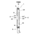
- Example 1 1 is an exploded perspective view of a dust collection filter according to a first embodiment of the present invention
- FIG. 2 is an external view of the dust collection filter
- FIG. 3 is a cross-sectional view of the dust collection filter.
- the dust collecting filter 1 of this embodiment includes two sheet-like bodies 2-1, 2-2, one frame 3, a power source 4, and an aromatic portion 5-1.
- An electric dust collecting filter provided.
- the planar bodies 2-1 and 2-2 are members for adsorbing dust in the air when air passes, and the planar bodies 2-1 and 2-2 are attached to both surfaces of the frame body 3, respectively. It has been. That is, the two planar bodies 2-1 and 2-2 are held by one frame body 3. A fragrance portion 5-1 that emits a fragrance is provided in the frame 3.
- FIG. 4 is a plan view of the planar body 2-1 as the first planar body
- FIG. 5 is an exploded perspective view of the planar body 2-1.
- the planar body 2-1 has the mesh electrode 20 as the first electrode in the form of a sheet formed by two insulating sheets 21 and 21 before and after (left of FIG. 5). , Right) and is covered.
- the mesh electrode 20 of the planar body 2-1 is connected to the positive electrode of the power supply 4 so that a positive voltage as a first voltage is applied.
- the planar body 2-1 is formed with a central circular hole 23 as a first ventilation hole. The central circular hole 23 penetrates the insulating sheets 21 and 21 and partially exposes the mesh electrode 20 inside.
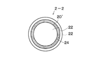
- FIG. 6 is a plan view of the planar body 2-2 as the second planar body
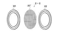
- FIG. 7 is an exploded perspective view of the planar body 2-2.
- the planar body 2-2 has a mesh electrode 20 ′ as a sheet-like second electrode, which is front and rear by two insulating sheets 22 and 22 (FIG. 7). The structure is covered by sandwiching from left and right).
- the mesh electrode 20 ′ of the planar body 2-2 is connected to the negative electrode of the power supply 4 so that a negative voltage as a second voltage is applied.
- a ring-shaped hole 24 as a second ventilation hole is formed.
- the ring-shaped hole 24 penetrates the insulating sheets 22 and 22 and partially exposes the mesh electrode 20 ′. Therefore, as shown in FIG. 3, the ring-shaped hole 24 provided in the planar body 2-2 is opened at a position shifted from the position of the central circular hole 23 by a predetermined distance in the radial direction.
- FIG. 8 is a plan view of the frame 3.
- each frame 3 is a ring-shaped body having substantially the same diameter as the planar bodies 2-1 and 2-2. 2-2 is pasted.
- the frame body 3 is made of ceramics, and the planar bodies 2-1 and 2-2 on both sides are firmly held by the frame body 3.
- Such a frame 3 is formed thick as shown in FIG. 3, so that a space S is formed in the gap between the planar bodies 2-1 and 2-2 and the inside of the frame 3. Has been.
- the fragrance 5-1 is provided on the frame 3. Specifically, as shown in FIGS. 3 and 8, the fragrance portion 5-1 was formed by mixing the fragrance M in the frame 3. In detail, after impregnating the essential oil of the fragrance M such as eucalyptus leaf oil, peppermint, tea tree, etc. into the ceramic plate, the ceramic plate is processed to form the frame 3 having the fragrance 5-1 did.
- the essential oil of the fragrance M such as eucalyptus leaf oil, peppermint, tea tree, etc.
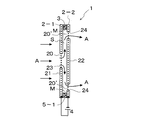
- FIG. 9 is a cross-sectional view for explaining the operation of the dust collection filter 1.
- the dust collection filter 1 of this embodiment is small, so it can be carried in a pocket and is easy to carry. Therefore, this small dust collection filter 1 can be easily attached before or after the air conditioner of the automobile. In other words, the dust collection filter 1 can be easily carried at any time, and can be attached to the entrance / exit of an arbitrary air passage or in the middle to collect dust.
- the dust collection filter 1 is disposed at the entrance / exit of an air conditioner or the like of an automobile so as to block the flow path of the air A as shown in FIG. Then, the power supply 4 of the dust collection filter 1 is turned on. Then, a positive voltage is applied to the mesh electrode 20 of the planar body 2-1, and a negative voltage is applied to the mesh electrode 20 'of the planar body 2-2. Thereby, the mesh electrode 20 and the mesh electrode 20 ′ are charged with opposite polarities. Then, in the vicinity of the mesh electrode 20 exposed in the central circular hole 23 of the planar body 2-1, and in the vicinity of the mesh electrode 20 'exposed in the ring-shaped hole 24 of the planar body 2-2, Discharge occurs.
- the air A on which the dust is electrostatically adsorbed passes through the ring-shaped hole 24 and flows out of the dust collection filter 1.
- the air A and dust flow through the dust collecting filter 1, so that the dust is electrostatically adsorbed to the planar body 2-1 and the planar body 2-2. Only the clean air A that has been removed by the planar bodies 2-1 and 2-2 flows out of the dust collection filter 1.
- the fragrance M is mixed in the frame 3 to form the fragrance portion 5-1, and the fragrance M is always diffused from the frame 3. Therefore, the fragrance M is diffused outward in the radial direction of the frame 3 (up and down direction in FIG. 9), and diffused inward of the frame 3 (inside the space S in FIG. 9).
- the fragrance M diffused in the space S flows out from the ring-shaped hole 24 of the dust collection filter 1 together with the air A, and the entire periphery of the dust collection filter 1 is wrapped in a fragrant fragrance by the fragrance M. .
- FIG. 10 is a sectional view showing a dust collecting filter according to the second embodiment of the present invention.
- the dust collection filter 1 of this embodiment is different from the first embodiment in that the fragrance portions 5-1 and 5-2 are provided on the planar bodies 2-1 and 2-2, respectively.
- the liquid fragrance M is impregnated into the insulating sheet 21 of the planar body 2-1, and the fragrance portion 5-1 is formed, and the liquid fragrance M is similarly insulated with the planar body 2-2.
- the fragrance 5-2 was formed by impregnating the sheet 22.
- the fragrance M is diffused from the planar bodies 2-1 and 2-2 of the dust collection filter 1 and flows out of the ring-shaped hole 24 of the planar body 2-2.
- the entire surroundings will be wrapped in a fragrant scent. Since other configurations, operations, and effects are the same as those in the first embodiment, description thereof is omitted.
- FIG. 11 is a sectional view showing a dust collecting filter according to a third embodiment of the present invention.
- the dust collection filter 1 of this embodiment is different from the first and second embodiments in that the fragrance 5-1 is provided in the space S.
- the solid fragrance M was scattered in the space S of the dust collection filter 1, and the fragrance M was adhered to the surface of the planar bodies 2-1 and 2-2 with an adhesive (not shown).
- FIG. 12 is a sectional view showing an air cleaner according to a fourth embodiment of the present invention.
- the air cleaner 100 of this embodiment includes a dust collection filter.
- the air cleaner 100 can be equipped with any of the dust collection filters 1 of the first to third embodiments.
- the dust collecting filter 1 of the first embodiment is provided.
- the air cleaner 100 has an air flow passage 102 in the housing 101.
- the inflow port 103 of the air flow passage 102 opens on the front surface of the housing 101 (the left side surface in FIG. 12).
- the air flow passage 102 passes through the inside of the casing 101 and reaches the upper surface of the casing 101 (the upper side surface in FIG. 12).
- the outflow port 104 opens on the upper surface of the housing 101.
- the fan 110 is attached to the rotating shaft 112 of the motor 111, and the fan 110 is disposed at the rear stage of the air flow passage 102.
- the motor 111 is connected to the controller 120. When the power button 121 of the controller 120 is turned on, the motor 111 is driven, and when the accelerator button 122 is pressed, the rotation speed of the motor 111 can be increased or decreased. .
- the dust collection filter 1 is detachably attached to an attachment portion 105 at the back of the inflow port 103. Specifically, as shown in FIG. 3, the dust collection filter 1 is disposed with the planar body 2-1 facing the inlet 103 and the planar body 2-2 facing the outlet 104. ing.
- the mesh electrodes 20 and 20 ′ of the planar bodies 2-1 and 2-2 are electrically connected to the power source 4 in the controller 120.
- the power source 4 rectifies and uses a commercial power source taken from the outside by the controller 120. Therefore, when the power button 121 is turned on, a predetermined voltage is applied to the mesh electrodes 20, 20 ′, and the dust collecting filter 1 is driven and the motor 111 is also driven.
- the accelerator button 122 functions only for the motor 111.
- the power button 121 of the controller 120 is turned on, and the dust collection filter 1 and the motor 111 are driven. Then, the fan 110 rotates and external air A is sucked from the inflow port 103.
- the air A passes through the dust collection filter 1, and as described in the first embodiment, dust in the air A is electrostatically adsorbed on the planar bodies 2-1 and 2-2 of the dust collection filter 1, Only the clean air A collected is discharged from the dust collection filter 1. Further, the fragrance of the fragrance M is diffused from the fragrance 5-1 of the dust collection filter 1.
- the scent of the air A and the fragrance M discharged and diffused into the air flow passage 102 is guided to the outlet 104 side by the fan 110 and is released from the outlet 104 around the air cleaner 100.
- the air cleaner 100 of this embodiment is equipped with the dust collecting filter 1 having the fragrance 5-1. Therefore, as in the conventional air purifier, the aroma apparatus and the essential oil volatilization are used as the fragrance. It is not necessary to make the device specially separate from the dust collection filter 1, and accordingly, the structure of the entire air cleaner can be simplified.
- the dust collection filter 1 is clogged due to long-term use, the flow of the scent of the air A and the fragrance M in the air flow passage 102 of the air cleaner 100 is stagnated, and the air cleaner 100 Will not work. Therefore, in this case, the used dust collection filter 1 is removed from the mounting portion 105, and a new dust filter 1 is replaced. As a result, the fragrance 5-1 and the filter 1 main body can be replaced at a time without having to be replaced separately. Since other configurations, operations, and effects are the same as those in the first to third embodiments, description thereof is omitted.
- this invention is not limited to the said Example, A various deformation
- the dust collecting filter 1 of the “electric dust collecting filter” that is charged by applying a certain voltage as the dust collecting filter is illustrated, but the dust collecting filter is not limited to this. Accordingly, an electrostatic filter that precharges a planar body or the like without using a voltage, a HEPA (High Efficiency Particulate Air) filter that captures dust by the fiber structure of the planar body, and the like are also included in the scope of the present invention. .
- HEPA High Efficiency Particulate Air
Landscapes
- Engineering & Computer Science (AREA)
- Chemical & Material Sciences (AREA)
- Health & Medical Sciences (AREA)
- Combustion & Propulsion (AREA)
- Mechanical Engineering (AREA)
- General Engineering & Computer Science (AREA)
- Life Sciences & Earth Sciences (AREA)
- Epidemiology (AREA)
- Chemical Kinetics & Catalysis (AREA)
- Animal Behavior & Ethology (AREA)
- General Health & Medical Sciences (AREA)
- Public Health (AREA)
- Veterinary Medicine (AREA)
- Electrostatic Separation (AREA)
- Disinfection, Sterilisation Or Deodorisation Of Air (AREA)
- Filtering Of Dispersed Particles In Gases (AREA)
Abstract
簡易な構造で、しかも、芳香部で使用する芳香剤の交換や集塵フィルタの交換が容易な集塵フィルタ及び空気清浄機を提供する。集塵フィルタ1は面状体2-1,2-2と枠体3と電源4と芳香部5-1とを備える。面状体2-1,2-2は空気中の塵を静電吸着するための部材である。枠体3は面状体2-1,2-2を保持すると共に空間Sを形成する部材である。芳香部5-1は枠体3にそれぞれ設けられている。具体的には、芳香剤Mを枠体3に混在されている。
Description
この発明は、芳香を放つ集塵フィルタ及び空気清浄機に関するものである。
従来、この種の空気清浄機は、例えば、特許文献1や特許文献2に記載のように、集塵フィルタを空気流通路内に取り付け、芳香を放つ芳香部を、空気流通路内に設けた構造をしている。
これにより、空気清浄機が、空気を流入口から空気流通路内に吸引し、空気内の塵等を空気流通路内に介在する集塵フィルタによって、除去した後、通路出口から排出する。そして、芳香部から放たれた芳香を空気流通路内の空気と共に、外部に排出して、ユーザの心身をリラックスさせたり、疲労回復を図っている。
これにより、空気清浄機が、空気を流入口から空気流通路内に吸引し、空気内の塵等を空気流通路内に介在する集塵フィルタによって、除去した後、通路出口から排出する。そして、芳香部から放たれた芳香を空気流通路内の空気と共に、外部に排出して、ユーザの心身をリラックスさせたり、疲労回復を図っている。
しかし、上記した従来の空気清浄機では、次のような問題がある。
すなわち、従来の空気清浄機では、芳香を放つ芳香部として、特別に製作したアロマ装置や精油揮散装置を用い、これらの装置を空気清浄機内に組み込んだ構成になっているので、空気清浄機の構造が複雑になり、製造コストが高くなる。また、使用済みの芳香剤や目詰まりがした集塵フィルタを、別々に交換しなければならず、交換作業が煩雑である。
すなわち、従来の空気清浄機では、芳香を放つ芳香部として、特別に製作したアロマ装置や精油揮散装置を用い、これらの装置を空気清浄機内に組み込んだ構成になっているので、空気清浄機の構造が複雑になり、製造コストが高くなる。また、使用済みの芳香剤や目詰まりがした集塵フィルタを、別々に交換しなければならず、交換作業が煩雑である。
この発明は、上述した課題を解決するためになされたもので、簡易な構造で、しかも、芳香部で使用する芳香剤の交換や集塵フィルタの交換が容易な集塵フィルタ及び空気清浄機を提供することを目的とする。
上記課題を解決するために、第1の発明に係る集塵フィルタは、空気の通過時に空気中の塵を吸着する1枚以上の面状体と、1枚以上の面状体を保持するための1以上の枠体と、芳香を放つ芳香部とを備える構成とした。
かかる構成により、この発明の集塵フィルタを空気清浄機等に組み込むことで、空気が、枠体で保持された面状体を通過する時に、空気中の塵が面状体によって吸着される。そして、芳香部からの芳香が、空気の流れに乗って、周囲に放散される。
使用済みの集塵フィルタを交換することで、芳香部とフィルタ本体とを一度に交換することができる。
また、芳香部が集塵フィルタに設けられているので、従来の空気清浄機のように、芳香部としてアロマ装置や精油揮散装置を、集塵フィルタとは別体に特製する必要がなく、その分、空気清浄機全体の構造を簡単にすることができる。この結果、この発明の集塵フィルタを用いた空気清浄機等の製造コストを低減化させることができる。
かかる構成により、この発明の集塵フィルタを空気清浄機等に組み込むことで、空気が、枠体で保持された面状体を通過する時に、空気中の塵が面状体によって吸着される。そして、芳香部からの芳香が、空気の流れに乗って、周囲に放散される。
使用済みの集塵フィルタを交換することで、芳香部とフィルタ本体とを一度に交換することができる。
また、芳香部が集塵フィルタに設けられているので、従来の空気清浄機のように、芳香部としてアロマ装置や精油揮散装置を、集塵フィルタとは別体に特製する必要がなく、その分、空気清浄機全体の構造を簡単にすることができる。この結果、この発明の集塵フィルタを用いた空気清浄機等の製造コストを低減化させることができる。
第2の発明に係る集塵フィルタは、第1の発明の集塵フィルタにおいて、シート状の第1の電極の少なくとも一方面が第1の絶縁シートで被覆され且つ第1の電圧がこの第1の電極に印加される第1の面状体と、シート状の第2の電極の少なくとも一方面が第2の絶縁シートで被覆され且つ第1の電圧と異なる第2の電圧がこの第2の電極に印加される第2の面状体とが、絶縁性の枠体を介して交互に積層され、且つ、第1の絶縁シートから第1の電極に渡って貫通し、第1の電極を内部に一部露出させた第1の通気孔が、第1の面状体に1つ以上設けられると共に、第2の絶縁シートから第2の電極に渡って貫通し、第2の電極を内部に一部露出させた第2の通気孔が、第2の面状体に1つ以上設けられ、平面視において、第2の通気孔の位置が、第1の通気孔の位置から所定距離だけずれるように、第2の通気孔が配設されている構成とした。
かかる構成により、第1の電圧を第1の面状体の第1の電極に印加すると共に、第2の電圧を第2の面状体の第2の電極に印加すると、第1の電極と第2の電極とが、互いに逆極性で帯電する。
また、第1の通気孔内に露出した第1の電極の近傍や第2の通気孔内に露出した第2の電極の近傍において、コロナ放電が発生する。このため、塵を含む空気が、前段の第1の面状体の第1の通気孔を通る際には、塵が、第1の電極の近傍のコロナ放電によって帯電させられる。そして、帯電した塵は、空気と共に、集塵フィルタ内部に流入する。
このとき、第2の通気孔が、第1の通気孔から所定距離だけずれているので、第1の面状体と第2の面状体との間に流入した空気と塵は、第1の通気孔から第2の通気孔に向かって面方向に移動し、第2の通気孔を通って、第2の面状体と後段の第1の面状体との間に流入する。
この際、上記第1の電極の近傍のコロナ放電によって帯電しなかった塵は、第2の通気孔内に露出した第2の電極の近傍のコロナ放電によって帯電させられる。
以後同様に、帯電した塵を含んだ空気は、フィルタ内を蛇行しながら流れ、最終的に、塵が第1及び第2の面状体によって除去され、清浄な空気だけが集塵フィルタから流出される。
また、上記のごとく、空気は、フィルタ内を蛇行しながら流れるので、フィルタ内を流れる時間が長くなり、その分、多くの塵を確実に静電吸着することができる。
かかる構成により、第1の電圧を第1の面状体の第1の電極に印加すると共に、第2の電圧を第2の面状体の第2の電極に印加すると、第1の電極と第2の電極とが、互いに逆極性で帯電する。
また、第1の通気孔内に露出した第1の電極の近傍や第2の通気孔内に露出した第2の電極の近傍において、コロナ放電が発生する。このため、塵を含む空気が、前段の第1の面状体の第1の通気孔を通る際には、塵が、第1の電極の近傍のコロナ放電によって帯電させられる。そして、帯電した塵は、空気と共に、集塵フィルタ内部に流入する。
このとき、第2の通気孔が、第1の通気孔から所定距離だけずれているので、第1の面状体と第2の面状体との間に流入した空気と塵は、第1の通気孔から第2の通気孔に向かって面方向に移動し、第2の通気孔を通って、第2の面状体と後段の第1の面状体との間に流入する。
この際、上記第1の電極の近傍のコロナ放電によって帯電しなかった塵は、第2の通気孔内に露出した第2の電極の近傍のコロナ放電によって帯電させられる。
以後同様に、帯電した塵を含んだ空気は、フィルタ内を蛇行しながら流れ、最終的に、塵が第1及び第2の面状体によって除去され、清浄な空気だけが集塵フィルタから流出される。
また、上記のごとく、空気は、フィルタ内を蛇行しながら流れるので、フィルタ内を流れる時間が長くなり、その分、多くの塵を確実に静電吸着することができる。
第3の発明に係る集塵フィルタは、第2の発明に係る集塵フィルタにおいて、芳香部を、芳香剤を枠体に混在することで形成した構成とする。
第4の発明に係る集塵フィルタは、第2の発明に係る集塵フィルタにおいて、芳香部を、芳香剤を面状体の絶縁シートに含浸させることで形成した構成とする。
第5の発明に係る集塵フィルタは、第2の発明に係る集塵フィルタにおいて、芳香部を、芳香剤を第1及び第2の面状体の間隙であって枠体の内側の空間に配置することで形成した構成とする。
また、第6の発明に係る空気清浄機は、第1の発明に係る集塵フィルタないし第5の発明に係る集塵フィルタのいずれかを備える構成とした。
かかる構成により、第1ないし第5の発明に係る集塵フィルタのいずれかを空気清浄機の空気出入り口近傍や空気流通路途中に組み込むことで、 空気が集塵フィルタを通過する時に、空気中の塵が集塵フィルタによって吸着される。そして、集塵フィルタに設けられた芳香部からの芳香が空気の流れに乗って、空気清浄機の周囲に放散される。
使用済みの集塵フィルタを交換することで、芳香部とフィルタ本体とを一度に交換することができる。
また、芳香部を有する集塵フィルタを用いることで、空気清浄機全体の構造を簡単にすることができ、その分、空気清浄機の製造コストを低減化することができる。
かかる構成により、第1ないし第5の発明に係る集塵フィルタのいずれかを空気清浄機の空気出入り口近傍や空気流通路途中に組み込むことで、 空気が集塵フィルタを通過する時に、空気中の塵が集塵フィルタによって吸着される。そして、集塵フィルタに設けられた芳香部からの芳香が空気の流れに乗って、空気清浄機の周囲に放散される。
使用済みの集塵フィルタを交換することで、芳香部とフィルタ本体とを一度に交換することができる。
また、芳香部を有する集塵フィルタを用いることで、空気清浄機全体の構造を簡単にすることができ、その分、空気清浄機の製造コストを低減化することができる。
以上詳しく説明したように、この発明によれば、使用済みの集塵フィルタを交換することで、芳香部とフィルタ本体とを一度に交換することができる、という優れた効果がある。
さらに、芳香部が集塵フィルタに設けられているので、空気清浄機全体の構造を簡単にすることができ、その分、空気清浄機の製造コストを低減化することができる、とい効果もある。
さらに、芳香部が集塵フィルタに設けられているので、空気清浄機全体の構造を簡単にすることができ、その分、空気清浄機の製造コストを低減化することができる、とい効果もある。
以下、この発明の最良の形態について図面を参照して説明する。
(実施例1)
図1は、この発明の第1実施例に係る集塵フィルタの分解斜視図であり、図2は、集塵フィルタの外観図であり、図3は、集塵フィルタの断面図である。
図1~図3に示すように、この実施例の集塵フィルタ1は、2枚の面状体2-1,2-2と1つの枠体3と電源4と芳香部5-1とを備えた電気集塵フィルタである。
図1は、この発明の第1実施例に係る集塵フィルタの分解斜視図であり、図2は、集塵フィルタの外観図であり、図3は、集塵フィルタの断面図である。
図1~図3に示すように、この実施例の集塵フィルタ1は、2枚の面状体2-1,2-2と1つの枠体3と電源4と芳香部5-1とを備えた電気集塵フィルタである。
面状体2-1,2-2は、空気の通過時に空気中の塵を吸着するための部材であり、面状体2-1,2-2が、枠体3の両面にそれぞれ貼り付けられている。つまり、2枚の面状体2-1,2-2は、1つの枠体3によって保持されている。
そして、芳香を放つ芳香部5-1が、枠体3に設けられている。
そして、芳香を放つ芳香部5-1が、枠体3に設けられている。
図4は、第1の面状体としての面状体2-1の平面図であり、図5は、面状体2-1の分解斜視図である。
図4及び図5に示すように、面状体2-1は、シート状の第1の電極としての網目状電極20を、2枚の絶縁シート21,21により、前,後(図5左,右)から挟んで被覆した構造になっている。
図3に示すように、面状体2-1の網目状電極20は、電源4の正極に接続され、第1の電圧としての正電圧が印加されるようになっている。
そして、このような面状体2-1には、第1の通気孔としての中心円孔23が形成されている。この中心円孔23は、絶縁シート21,21を貫通しており、網目状電極20を内部に一部露出させている。
図4及び図5に示すように、面状体2-1は、シート状の第1の電極としての網目状電極20を、2枚の絶縁シート21,21により、前,後(図5左,右)から挟んで被覆した構造になっている。
図3に示すように、面状体2-1の網目状電極20は、電源4の正極に接続され、第1の電圧としての正電圧が印加されるようになっている。
そして、このような面状体2-1には、第1の通気孔としての中心円孔23が形成されている。この中心円孔23は、絶縁シート21,21を貫通しており、網目状電極20を内部に一部露出させている。
図6は、第2の面状体としての面状体2-2の平面図であり、図7は、面状体2-2の分解斜視図である。
図6及び図7に示すように、面状体2-2は、シート状の第2の電極としての網目状電極20’を、2枚の絶縁シート22,22により、前,後(図7左,右)から挟んで被覆した構造になっている。
図3に示すように、面状体2-2の網目状電極20’は、電源4の負極に接続され、第2の電圧としての負電圧が印加されるようになっている。
そして、このような面状体2-2には、第2の通気孔としてのリング状孔24が形成されている。このリング状孔24は、絶縁シート22,22を貫通しており、網目状電極20’を内部に一部露出させている。
したがって、面状体2-2に設けられたリング状孔24は、図3に示すように、中心円孔23の位置から径方向に所定距離ずれた位置で開口している。
図6及び図7に示すように、面状体2-2は、シート状の第2の電極としての網目状電極20’を、2枚の絶縁シート22,22により、前,後(図7左,右)から挟んで被覆した構造になっている。
図3に示すように、面状体2-2の網目状電極20’は、電源4の負極に接続され、第2の電圧としての負電圧が印加されるようになっている。
そして、このような面状体2-2には、第2の通気孔としてのリング状孔24が形成されている。このリング状孔24は、絶縁シート22,22を貫通しており、網目状電極20’を内部に一部露出させている。
したがって、面状体2-2に設けられたリング状孔24は、図3に示すように、中心円孔23の位置から径方向に所定距離ずれた位置で開口している。
図8は、枠体3の平面図である。
図8に示すように、各枠体3は、面状体2-1,2-2とほぼ同径のリング状体であり、この枠体3の両面全面に、面状体2-1,2-2が貼り付けられている。
枠体3は、セラミックスで形成されており、両面の面状体2-1,2-2が、枠体3によって強固に保持されている。
このような枠体3は、図3に示すように、肉厚に形成されており、これにより、空間Sが、面状体2-1,2-2と枠体3内側との間隙に形成されている。
図8に示すように、各枠体3は、面状体2-1,2-2とほぼ同径のリング状体であり、この枠体3の両面全面に、面状体2-1,2-2が貼り付けられている。
枠体3は、セラミックスで形成されており、両面の面状体2-1,2-2が、枠体3によって強固に保持されている。
このような枠体3は、図3に示すように、肉厚に形成されており、これにより、空間Sが、面状体2-1,2-2と枠体3内側との間隙に形成されている。
芳香部5-1は、枠体3に設けられている。
具体的には、図3及び図8に示すように、芳香剤Mを枠体3に混在することで、芳香部5-1を形成した。
詳しくは、ユーカリ葉油,ペパーミント,ティーツリー等の芳香剤Mの精油を、セラミックス板に浸み込ませた後、セラミックス板を加工することで、芳香部5-1を有する枠体3を形成した。
具体的には、図3及び図8に示すように、芳香剤Mを枠体3に混在することで、芳香部5-1を形成した。
詳しくは、ユーカリ葉油,ペパーミント,ティーツリー等の芳香剤Mの精油を、セラミックス板に浸み込ませた後、セラミックス板を加工することで、芳香部5-1を有する枠体3を形成した。
次に、この実施例の集塵フィルタ1が示す作用及び効果について説明する。
図9は、集塵フィルタ1の作用を説明するための断面図である。
図2等で示したように、この実施例の集塵フィルタ1は、小型であるので、ポケットに入れて携帯することができ、持ち運びが容易である。
したがって、この小型の集塵フィルタ1を、自動車のエアコンの前や後に簡単に取り付けることができる。
つまり、集塵フィルタ1をいつでも容易に携帯して、任意の空気通路の出入り口や途中に取り付けて、集塵を行うことができる。
図9は、集塵フィルタ1の作用を説明するための断面図である。
図2等で示したように、この実施例の集塵フィルタ1は、小型であるので、ポケットに入れて携帯することができ、持ち運びが容易である。
したがって、この小型の集塵フィルタ1を、自動車のエアコンの前や後に簡単に取り付けることができる。
つまり、集塵フィルタ1をいつでも容易に携帯して、任意の空気通路の出入り口や途中に取り付けて、集塵を行うことができる。
具体的には、集塵フィルタ1を、自動車のエアコン等の出入り口に配置して、図9に示すように、空気Aの流路を遮るようにする。
そして、集塵フィルタ1の電源4をオンにする。すると、正電圧が面状体2-1の網目状電極20に印加され、負電圧が面状体2-2の網目状電極20’に印加される。
これにより、網目状電極20と網目状電極20’とが、互いに逆極性で帯電する。
そして、面状体2-1の中心円孔23内に露出した網目状電極20の近傍や、面状体2-2のリング状孔24内に露出した網目状電極20’の近傍において、コロナ放電が発生する。
そして、集塵フィルタ1の電源4をオンにする。すると、正電圧が面状体2-1の網目状電極20に印加され、負電圧が面状体2-2の網目状電極20’に印加される。
これにより、網目状電極20と網目状電極20’とが、互いに逆極性で帯電する。
そして、面状体2-1の中心円孔23内に露出した網目状電極20の近傍や、面状体2-2のリング状孔24内に露出した網目状電極20’の近傍において、コロナ放電が発生する。
このため、塵を含む空気Aが、前段の面状体2-1の中心円孔23を通る際には、塵が、網目状電極20の近傍のコロナ放電によって帯電させられる。そして、帯電した塵は、空気Aと共に、空間S内に流入する。
ところで、面状体2-2のリング状孔24は、中心円孔23から径方向に所定距離だけずれている。
このため、面状体2-1と面状体2-2との間の空間Sに流入した空気Aと塵は、中心円孔23からリング状孔24に向かって径方向に移動し、リング状孔24内に入り込む。
このとき、面状体2-1の網目状電極20によって帯電された塵は、逆極性の面状体2-2の表面に静電吸着される。
ところで、面状体2-2のリング状孔24は、中心円孔23から径方向に所定距離だけずれている。
このため、面状体2-1と面状体2-2との間の空間Sに流入した空気Aと塵は、中心円孔23からリング状孔24に向かって径方向に移動し、リング状孔24内に入り込む。
このとき、面状体2-1の網目状電極20によって帯電された塵は、逆極性の面状体2-2の表面に静電吸着される。
そして、塵が静電吸着された空気Aは、リング状孔24を通過して、集塵フィルタ1の外部に流出する。
以上のように、空気Aと塵とが集塵フィルタ1内を流れることにより、塵が、面状体2-1や面状体2-2に静電吸着されるので、最終的に、塵が面状体2-1,2-2によって除去された清浄な空気Aだけが、集塵フィルタ1から流出されることとなる。
ところで、この実施例では、芳香剤Mを枠体3に混在させて、芳香部5-1を形成しており、芳香剤Mが常時枠体3から放散されている。
このため、芳香剤Mは、枠体3の径方向外方(図9の上下方向)に放散されると共に、枠体3の内方(図9の空間S内部)に放散される。空間S内に放散された芳香剤Mは、空気Aと共に、集塵フィルタ1のリング状孔24から流出され、集塵フィルタ1の周囲全体が、芳香剤Mによる香ばしい香りに包まれることとなる。
このため、芳香剤Mは、枠体3の径方向外方(図9の上下方向)に放散されると共に、枠体3の内方(図9の空間S内部)に放散される。空間S内に放散された芳香剤Mは、空気Aと共に、集塵フィルタ1のリング状孔24から流出され、集塵フィルタ1の周囲全体が、芳香剤Mによる香ばしい香りに包まれることとなる。
(実施例2)
次に、この発明の第2実施例について説明する。
図10は、この発明の第2実施例に係る集塵フィルタを示す断面図である。
この実施例の集塵フィルタ1では、芳香部5-1,5-2を面状体2-1,2-2にそれぞれ設けた点が、上記第1実施例と異なる。
次に、この発明の第2実施例について説明する。
図10は、この発明の第2実施例に係る集塵フィルタを示す断面図である。
この実施例の集塵フィルタ1では、芳香部5-1,5-2を面状体2-1,2-2にそれぞれ設けた点が、上記第1実施例と異なる。
具体的には、液状の芳香剤Mを面状体2-1の絶縁シート21に含浸させて、芳香部5-1を形成し、同じく液状の芳香剤Mを面状体2-2の絶縁シート22に含浸させて、芳香部5-2を形成した。
かかる構成により、芳香剤Mが、集塵フィルタ1の面状体2-1,2-2から放散されると共に、面状体2-2のリング状孔24から流出され、集塵フィルタ1の周囲全体が、香ばしい香りに包まれることとなる。
その他の構成、作用及び効果は、上記第1実施例と同様であるので、それらの記載は省略する。
その他の構成、作用及び効果は、上記第1実施例と同様であるので、それらの記載は省略する。
(実施例3)
次に、この発明の第3実施例について説明する。
図11は、この発明の第3実施例に係る集塵フィルタを示す断面図である。
この実施例の集塵フィルタ1では、芳香部5-1を空間Sに設けた点が、上記第1及び第2実施例と異なる。
次に、この発明の第3実施例について説明する。
図11は、この発明の第3実施例に係る集塵フィルタを示す断面図である。
この実施例の集塵フィルタ1では、芳香部5-1を空間Sに設けた点が、上記第1及び第2実施例と異なる。
具体的には、固形の芳香剤Mを集塵フィルタ1の空間S内に散在させ、図示しない接着剤等で、芳香剤Mを面状体2-1,2-2の表面に接着した。
かかる構成により、空気Aが、面状体2-1の中心円孔23から流入して、集塵フィルタ1の空間Sを通る。すると、芳香剤Mの香りを含んだ空気Aが、面状体2-2のリング状孔24から流出され、集塵フィルタ1の周囲全体が、香ばしい香りに包まれることとなる。
その他の構成、作用及び効果は、上記第1及び第2実施例と同様であるので、それらの記載は省略する。
その他の構成、作用及び効果は、上記第1及び第2実施例と同様であるので、それらの記載は省略する。
(実施例4)
次に、この発明の第4実施例について説明する。
図12は、この発明の第4実施例に係る空気清浄機を示す断面図である。
図12に示すように、この実施例の空気清浄機100は、集塵フィルタを備えている。空気清浄機100には、上記第1~第3実施例の集塵フィルタ1のいずれのフィルタでも装備することができる。この実施例では、第1実施例の集塵フィルタ1を装備した。
次に、この発明の第4実施例について説明する。
図12は、この発明の第4実施例に係る空気清浄機を示す断面図である。
図12に示すように、この実施例の空気清浄機100は、集塵フィルタを備えている。空気清浄機100には、上記第1~第3実施例の集塵フィルタ1のいずれのフィルタでも装備することができる。この実施例では、第1実施例の集塵フィルタ1を装備した。
空気清浄機100は、空気流通路102を筐体101内に有している。
具体的には、空気流通路102の流入口103が、筐体101の前面(図12の左側面)に開口している。そして、空気流通路102が、筐体101内部を通って、筐体101の上面(図12の上側面)に至る。最後部で、流出口104が、筐体101の上面に開口している。
具体的には、空気流通路102の流入口103が、筐体101の前面(図12の左側面)に開口している。そして、空気流通路102が、筐体101内部を通って、筐体101の上面(図12の上側面)に至る。最後部で、流出口104が、筐体101の上面に開口している。
ファン110が、モータ111の回転軸112に取り付けられ、このファン110が、空気流通路102の後段に配設されている。
モータ111は、コントローラ120に接続されており、コントローラ120の電源ボタン121をオンにすることで、モータ111が駆動し、アクセルボタン122を押すことで、モータ111の回転速度を増減させることができる。
モータ111は、コントローラ120に接続されており、コントローラ120の電源ボタン121をオンにすることで、モータ111が駆動し、アクセルボタン122を押すことで、モータ111の回転速度を増減させることができる。
集塵フィルタ1は、流入口103の奥の取付部105に着脱自在に取り付けられている。
具体的には、図3に示すように、集塵フィルタ1の面状体2-1を流入口103側に向け、面状体2-2を流出口104側に向けた状態で、配置されている。
そして、面状体2-1,2-2の網目状電極20,20’が、コントローラ120内の電源4に電気的に接続されている。ここでは、電源4は、コントローラ120が外部から取り入れた商用電源を整流して用いる。
したがって、電源ボタン121をオンにすると、所定の電圧が網目状電極20,20’に印加されて、集塵フィルタ1が駆動状態になると共に、モータ111も駆動状態になる。なお、アクセルボタン122は、モータ111にのみ機能する。
具体的には、図3に示すように、集塵フィルタ1の面状体2-1を流入口103側に向け、面状体2-2を流出口104側に向けた状態で、配置されている。
そして、面状体2-1,2-2の網目状電極20,20’が、コントローラ120内の電源4に電気的に接続されている。ここでは、電源4は、コントローラ120が外部から取り入れた商用電源を整流して用いる。
したがって、電源ボタン121をオンにすると、所定の電圧が網目状電極20,20’に印加されて、集塵フィルタ1が駆動状態になると共に、モータ111も駆動状態になる。なお、アクセルボタン122は、モータ111にのみ機能する。
次に、この実施例の空気清浄機100の作用及び効果について説明する。
コントローラ120の電源ボタン121をオンにして、集塵フィルタ1とモータ111を駆動状態にする。
すると、ファン110が回転し、外部の空気Aが、流入口103から吸気される。
空気Aは集塵フィルタ1を通過し、上記第1実施例で説明したように、空気A内の塵が、集塵フィルタ1の面状体2-1,2-2に静電吸着され、集塵された清潔な空気Aのみが、集塵フィルタ1から流出される。また、芳香剤Mの香りが、集塵フィルタ1の芳香部5-1から放散される。
空気流通路102中に流出及び放散された空気Aと芳香剤Mの香りは、ファン110によって、流出口104側に導かれ、流出口104から、空気清浄機100の周囲に放出される。
コントローラ120の電源ボタン121をオンにして、集塵フィルタ1とモータ111を駆動状態にする。
すると、ファン110が回転し、外部の空気Aが、流入口103から吸気される。
空気Aは集塵フィルタ1を通過し、上記第1実施例で説明したように、空気A内の塵が、集塵フィルタ1の面状体2-1,2-2に静電吸着され、集塵された清潔な空気Aのみが、集塵フィルタ1から流出される。また、芳香剤Mの香りが、集塵フィルタ1の芳香部5-1から放散される。
空気流通路102中に流出及び放散された空気Aと芳香剤Mの香りは、ファン110によって、流出口104側に導かれ、流出口104から、空気清浄機100の周囲に放出される。
このように、この実施例の空気清浄機100では、芳香部5-1を有した集塵フィルタ1を装備しているので、従来の空気清浄機のように、芳香部としてアロマ装置や精油揮散装置を、集塵フィルタ1とは別体に特製する必要がなく、その分、空気清浄機全体の構造を簡単にすることができる。
そして、長期の使用によって、集塵フィルタ1に目詰まり等が生じた場合には、空気清浄機100の空気流通路102内の空気Aや芳香剤Mの香りの流れが滞り、空気清浄機100が機能しなくなる。
したがって、この場合には、使用済みの集塵フィルタ1を取付部105から取り外し、新たな塵フィルタ1を交換する。これにより、芳香部5-1とフィルタ1本体とを別々に交換することなく、一度で交換することができる。
その他の構成、作用及び効果は、上記第1ないし第3実施例と同様であるので、それらの記載は省略する。
そして、長期の使用によって、集塵フィルタ1に目詰まり等が生じた場合には、空気清浄機100の空気流通路102内の空気Aや芳香剤Mの香りの流れが滞り、空気清浄機100が機能しなくなる。
したがって、この場合には、使用済みの集塵フィルタ1を取付部105から取り外し、新たな塵フィルタ1を交換する。これにより、芳香部5-1とフィルタ1本体とを別々に交換することなく、一度で交換することができる。
その他の構成、作用及び効果は、上記第1ないし第3実施例と同様であるので、それらの記載は省略する。
なお、この発明は、上記実施例に限定されるものではなく、発明の要旨の範囲内において種々の変形や変更が可能である。
例えば、上記実施例では集塵フィルタとして一定の電圧を印加して帯電させる「電気集塵フィルタ」の集塵フィルタ1を例示したが、集塵フィルタは、これに限定されない。
したがって、電圧を使用せず、面状体等を予め帯電させおく静電気フィルタや、面状体の繊維構造によって塵を捕獲するHEPA( High Efficiency Particulate Air)フィルタ等も、この発明の範囲に含まれる。
例えば、上記実施例では集塵フィルタとして一定の電圧を印加して帯電させる「電気集塵フィルタ」の集塵フィルタ1を例示したが、集塵フィルタは、これに限定されない。
したがって、電圧を使用せず、面状体等を予め帯電させおく静電気フィルタや、面状体の繊維構造によって塵を捕獲するHEPA( High Efficiency Particulate Air)フィルタ等も、この発明の範囲に含まれる。
1…集塵フィルタ、 2-1,2-2…面状体、 3…枠体、 4…電源、 5-1,5-2…芳香部、 20,20’…網目状電極、 21,22…絶縁シ-ト、 23…中心円孔、 24…リング状孔、 100…空気清浄機、 101…筐体、 102…空気流通路、 103…流入口、 104…流出口、 105…取付部、 110…ファン、 111…モ-タ、 112…回転軸、 120…コントローラ、 121…電源ボタン、 122…アクセルボタン、 S…空間、 M…芳香剤、 A…空気。
Claims (6)
- 空気の通過時に空気中の塵を吸着する1枚以上の面状体と、
上記1枚以上の面状体を保持するための1以上の枠体と、
芳香を放つ芳香部と
を備えることを特徴とする集塵フィルタ。 - 請求項1に記載の集塵フィルタにおいて、
シート状の第1の電極の少なくとも一方面が第1の絶縁シートで被覆され且つ第1の電圧がこの第1の電極に印加される第1の上記面状体と、シート状の第2の電極の少なくとも一方面が第2の絶縁シートで被覆され且つ上記第1の電圧と異なる第2の電圧がこの第2の電極に印加される第2の上記面状体とが、絶縁性の上記枠体を介して交互に積層され、
且つ、上記第1の絶縁シートから第1の電極に渡って貫通し、第1の電極を内部に一部露出させた第1の通気孔が、上記第1の面状体に1つ以上設けられると共に、上記第2の絶縁シートから第2の電極に渡って貫通し、第2の電極を内部に一部露出させた第2の通気孔が、上記第2の面状体に1つ以上設けられ、
平面視において、上記第2の通気孔の位置が、上記第1の通気孔の位置から所定距離だけずれるように、第2の通気孔が配設されている、
ことを特徴とする集塵フィルタ。 - 請求項2に記載の集塵フィルタにおいて、
上記芳香部を、芳香剤を上記枠体に混在することで形成した、
ことを特徴とする集塵フィルタ。 - 請求項2に記載の集塵フィルタにおいて、
上記芳香部を、芳香剤を上記面状体の絶縁シートに含浸させることで形成した、
ことを特徴とする集塵フィルタ。 - 請求項2に記載の集塵フィルタにおいて、
上記芳香部を、芳香剤を上記第1及び第2の面状体の間隙であって上記枠体の内側の空間に配置することで形成した、
ことを特徴とする集塵フィルタ。 - 請求項1ないし請求項5のいずれかに記載の集塵フィルタを備える、
ことを特徴とする空気清浄機。
Applications Claiming Priority (2)
| Application Number | Priority Date | Filing Date | Title |
|---|---|---|---|
| JP2016-256744 | 2016-12-28 | ||
| JP2016256744 | 2016-12-28 |
Publications (1)
| Publication Number | Publication Date |
|---|---|
| WO2018123383A1 true WO2018123383A1 (ja) | 2018-07-05 |
Family
ID=62708028
Family Applications (1)
| Application Number | Title | Priority Date | Filing Date |
|---|---|---|---|
| PCT/JP2017/042307 Ceased WO2018123383A1 (ja) | 2016-12-28 | 2017-11-25 | 集塵フィルタ及び空気清浄機 |
Country Status (2)
| Country | Link |
|---|---|
| TW (1) | TW201829065A (ja) |
| WO (1) | WO2018123383A1 (ja) |
Cited By (1)
| Publication number | Priority date | Publication date | Assignee | Title |
|---|---|---|---|---|
| CN112212448A (zh) * | 2020-10-10 | 2021-01-12 | 东莞市净诺环境科技股份有限公司 | 一种插入式滤芯结构的新型空气净化器 |
Families Citing this family (1)
| Publication number | Priority date | Publication date | Assignee | Title |
|---|---|---|---|---|
| US11318219B1 (en) * | 2020-11-05 | 2022-05-03 | Bloomy Lotus Limited | Volcanic rock fluid diffuser |
Citations (7)
| Publication number | Priority date | Publication date | Assignee | Title |
|---|---|---|---|---|
| JPS49144544U (ja) * | 1973-04-10 | 1974-12-13 | ||
| US4118226A (en) * | 1977-03-22 | 1978-10-03 | Richard Lawrence Bourassa | Combination air filter and air treating device |
| JPS6183415U (ja) * | 1984-11-02 | 1986-06-02 | ||
| JPH0498129U (ja) * | 1991-01-18 | 1992-08-25 | ||
| JP2003329277A (ja) * | 2002-05-08 | 2003-11-19 | Toshio Sakurazawa | 空気清浄化手段を備えたレンジフード |
| JP2006046730A (ja) * | 2004-08-02 | 2006-02-16 | Sharp Corp | 集塵フィルター及びそれを用いた空気清浄機 |
| WO2016027635A1 (ja) * | 2014-08-18 | 2016-02-25 | 株式会社クリエイティブテクノロジー | 集塵装置 |
-
2017
- 2017-11-25 WO PCT/JP2017/042307 patent/WO2018123383A1/ja not_active Ceased
- 2017-12-07 TW TW106142950A patent/TW201829065A/zh unknown
Patent Citations (7)
| Publication number | Priority date | Publication date | Assignee | Title |
|---|---|---|---|---|
| JPS49144544U (ja) * | 1973-04-10 | 1974-12-13 | ||
| US4118226A (en) * | 1977-03-22 | 1978-10-03 | Richard Lawrence Bourassa | Combination air filter and air treating device |
| JPS6183415U (ja) * | 1984-11-02 | 1986-06-02 | ||
| JPH0498129U (ja) * | 1991-01-18 | 1992-08-25 | ||
| JP2003329277A (ja) * | 2002-05-08 | 2003-11-19 | Toshio Sakurazawa | 空気清浄化手段を備えたレンジフード |
| JP2006046730A (ja) * | 2004-08-02 | 2006-02-16 | Sharp Corp | 集塵フィルター及びそれを用いた空気清浄機 |
| WO2016027635A1 (ja) * | 2014-08-18 | 2016-02-25 | 株式会社クリエイティブテクノロジー | 集塵装置 |
Cited By (1)
| Publication number | Priority date | Publication date | Assignee | Title |
|---|---|---|---|---|
| CN112212448A (zh) * | 2020-10-10 | 2021-01-12 | 东莞市净诺环境科技股份有限公司 | 一种插入式滤芯结构的新型空气净化器 |
Also Published As
| Publication number | Publication date |
|---|---|
| TW201829065A (zh) | 2018-08-16 |
Similar Documents
| Publication | Publication Date | Title |
|---|---|---|
| CN101232932A (zh) | 提供结合除味的空气净化的系统和方法 | |
| JP2005055114A (ja) | 空気清浄機 | |
| JP2018516754A (ja) | 湿式型空気清浄器 | |
| KR101740497B1 (ko) | 습식 공기청정기 | |
| CA3056313C (en) | Corrugated filtration media for polarizing air cleaner | |
| WO2018123383A1 (ja) | 集塵フィルタ及び空気清浄機 | |
| JP2009536281A (ja) | 改良されたフィルタ媒体による能動電界分極媒体型エアクリーナ | |
| CN101743049A (zh) | 色粉粉尘过滤器 | |
| KR20170046326A (ko) | 회전형 가습필터 및 이를 구비하는 가습공기청정기 | |
| WO2016031782A1 (ja) | 空気清浄機 | |
| JP7196550B2 (ja) | 空気清浄装置 | |
| JP4683149B2 (ja) | 液処理用放電ユニット、及び調湿装置 | |
| JP2014064964A (ja) | ミスト発生装置 | |
| JP6020805B2 (ja) | 空気清浄機 | |
| WO2016031784A1 (ja) | 空気清浄機 | |
| CN206016905U (zh) | 一种机油滤清器 | |
| WO2015186804A1 (ja) | 空気清浄機 | |
| JP6020843B2 (ja) | 空気清浄機 | |
| JP2016180585A (ja) | 空気清浄機 | |
| JP6877119B2 (ja) | 集塵装置、空気清浄機 | |
| CN203577512U (zh) | 空气净化器 | |
| KR20210140929A (ko) | 공기청정기 | |
| CN205878385U (zh) | 空气清净装置及其过滤组件 | |
| KR101896146B1 (ko) | 가습 공기 청정기 | |
| JP2010043833A (ja) | 調湿装置 |
Legal Events
| Date | Code | Title | Description |
|---|---|---|---|
| 121 | Ep: the epo has been informed by wipo that ep was designated in this application |
Ref document number: 17889242 Country of ref document: EP Kind code of ref document: A1 |
|
| NENP | Non-entry into the national phase |
Ref country code: DE |
|
| 122 | Ep: pct application non-entry in european phase |
Ref document number: 17889242 Country of ref document: EP Kind code of ref document: A1 |
|
| NENP | Non-entry into the national phase |
Ref country code: JP |