WO2018123270A1 - Automatic inspection system and automatic inspection method - Google Patents
Automatic inspection system and automatic inspection method Download PDFInfo
- Publication number
- WO2018123270A1 WO2018123270A1 PCT/JP2017/039938 JP2017039938W WO2018123270A1 WO 2018123270 A1 WO2018123270 A1 WO 2018123270A1 JP 2017039938 W JP2017039938 W JP 2017039938W WO 2018123270 A1 WO2018123270 A1 WO 2018123270A1
- Authority
- WO
- WIPO (PCT)
- Prior art keywords
- wireless
- measurement data
- wireless slave
- data
- time zone
- Prior art date
Links
- 238000007689 inspection Methods 0.000 title claims abstract description 54
- 238000000034 method Methods 0.000 title claims description 19
- 238000013480 data collection Methods 0.000 claims abstract description 92
- 238000005259 measurement Methods 0.000 claims description 130
- 238000004891 communication Methods 0.000 claims description 21
- 238000001514 detection method Methods 0.000 claims description 4
- 230000004044 response Effects 0.000 description 37
- 238000010586 diagram Methods 0.000 description 16
- 238000007405 data analysis Methods 0.000 description 11
- 230000005540 biological transmission Effects 0.000 description 9
- 238000012545 processing Methods 0.000 description 9
- 238000004458 analytical method Methods 0.000 description 7
- 230000002776 aggregation Effects 0.000 description 5
- 238000004220 aggregation Methods 0.000 description 5
- 230000006870 function Effects 0.000 description 5
- 230000008569 process Effects 0.000 description 5
- 230000008859 change Effects 0.000 description 3
- 230000008901 benefit Effects 0.000 description 2
- 238000003384 imaging method Methods 0.000 description 2
- 230000004048 modification Effects 0.000 description 2
- 238000012986 modification Methods 0.000 description 2
- 230000000737 periodic effect Effects 0.000 description 2
- 230000009467 reduction Effects 0.000 description 2
- XLYOFNOQVPJJNP-UHFFFAOYSA-N water Substances O XLYOFNOQVPJJNP-UHFFFAOYSA-N 0.000 description 2
- 235000008694 Humulus lupulus Nutrition 0.000 description 1
- 230000032683 aging Effects 0.000 description 1
- 230000000295 complement effect Effects 0.000 description 1
- 238000004590 computer program Methods 0.000 description 1
- 230000005494 condensation Effects 0.000 description 1
- 238000009833 condensation Methods 0.000 description 1
- 230000005611 electricity Effects 0.000 description 1
- 238000010191 image analysis Methods 0.000 description 1
- 239000007788 liquid Substances 0.000 description 1
- 238000012423 maintenance Methods 0.000 description 1
- 229910044991 metal oxide Inorganic materials 0.000 description 1
- 150000004706 metal oxides Chemical class 0.000 description 1
- 239000004065 semiconductor Substances 0.000 description 1
- 239000007787 solid Substances 0.000 description 1
- 230000002123 temporal effect Effects 0.000 description 1
Images


Classifications
-
- G—PHYSICS
- G08—SIGNALLING
- G08C—TRANSMISSION SYSTEMS FOR MEASURED VALUES, CONTROL OR SIMILAR SIGNALS
- G08C17/00—Arrangements for transmitting signals characterised by the use of a wireless electrical link
-
- G—PHYSICS
- G08—SIGNALLING
- G08C—TRANSMISSION SYSTEMS FOR MEASURED VALUES, CONTROL OR SIMILAR SIGNALS
- G08C15/00—Arrangements characterised by the use of multiplexing for the transmission of a plurality of signals over a common path
-
- G—PHYSICS
- G08—SIGNALLING
- G08C—TRANSMISSION SYSTEMS FOR MEASURED VALUES, CONTROL OR SIMILAR SIGNALS
- G08C15/00—Arrangements characterised by the use of multiplexing for the transmission of a plurality of signals over a common path
- G08C15/06—Arrangements characterised by the use of multiplexing for the transmission of a plurality of signals over a common path successively, i.e. using time division
-
- H—ELECTRICITY
- H04—ELECTRIC COMMUNICATION TECHNIQUE
- H04Q—SELECTING
- H04Q9/00—Arrangements in telecontrol or telemetry systems for selectively calling a substation from a main station, in which substation desired apparatus is selected for applying a control signal thereto or for obtaining measured values therefrom
-
- H—ELECTRICITY
- H04—ELECTRIC COMMUNICATION TECHNIQUE
- H04W—WIRELESS COMMUNICATION NETWORKS
- H04W4/00—Services specially adapted for wireless communication networks; Facilities therefor
- H04W4/30—Services specially adapted for particular environments, situations or purposes
- H04W4/38—Services specially adapted for particular environments, situations or purposes for collecting sensor information
-
- H—ELECTRICITY
- H04—ELECTRIC COMMUNICATION TECHNIQUE
- H04W—WIRELESS COMMUNICATION NETWORKS
- H04W52/00—Power management, e.g. TPC [Transmission Power Control], power saving or power classes
- H04W52/02—Power saving arrangements
-
- H—ELECTRICITY
- H04—ELECTRIC COMMUNICATION TECHNIQUE
- H04W—WIRELESS COMMUNICATION NETWORKS
- H04W52/00—Power management, e.g. TPC [Transmission Power Control], power saving or power classes
- H04W52/02—Power saving arrangements
- H04W52/0203—Power saving arrangements in the radio access network or backbone network of wireless communication networks
-
- H—ELECTRICITY
- H04—ELECTRIC COMMUNICATION TECHNIQUE
- H04W—WIRELESS COMMUNICATION NETWORKS
- H04W74/00—Wireless channel access
- H04W74/04—Scheduled access
-
- H—ELECTRICITY
- H04—ELECTRIC COMMUNICATION TECHNIQUE
- H04Q—SELECTING
- H04Q2209/00—Arrangements in telecontrol or telemetry systems
-
- H—ELECTRICITY
- H04—ELECTRIC COMMUNICATION TECHNIQUE
- H04Q—SELECTING
- H04Q2209/00—Arrangements in telecontrol or telemetry systems
- H04Q2209/40—Arrangements in telecontrol or telemetry systems using a wireless architecture
-
- H—ELECTRICITY
- H04—ELECTRIC COMMUNICATION TECHNIQUE
- H04Q—SELECTING
- H04Q2209/00—Arrangements in telecontrol or telemetry systems
- H04Q2209/70—Arrangements in the main station, i.e. central controller
- H04Q2209/75—Arrangements in the main station, i.e. central controller by polling or interrogating the sub-stations
-
- H—ELECTRICITY
- H04—ELECTRIC COMMUNICATION TECHNIQUE
- H04Q—SELECTING
- H04Q2209/00—Arrangements in telecontrol or telemetry systems
- H04Q2209/80—Arrangements in the sub-station, i.e. sensing device
- H04Q2209/88—Providing power supply at the sub-station
- H04Q2209/883—Providing power supply at the sub-station where the sensing device enters an active or inactive mode
-
- H—ELECTRICITY
- H04—ELECTRIC COMMUNICATION TECHNIQUE
- H04W—WIRELESS COMMUNICATION NETWORKS
- H04W84/00—Network topologies
- H04W84/18—Self-organising networks, e.g. ad-hoc networks or sensor networks
-
- Y—GENERAL TAGGING OF NEW TECHNOLOGICAL DEVELOPMENTS; GENERAL TAGGING OF CROSS-SECTIONAL TECHNOLOGIES SPANNING OVER SEVERAL SECTIONS OF THE IPC; TECHNICAL SUBJECTS COVERED BY FORMER USPC CROSS-REFERENCE ART COLLECTIONS [XRACs] AND DIGESTS
- Y02—TECHNOLOGIES OR APPLICATIONS FOR MITIGATION OR ADAPTATION AGAINST CLIMATE CHANGE
- Y02D—CLIMATE CHANGE MITIGATION TECHNOLOGIES IN INFORMATION AND COMMUNICATION TECHNOLOGIES [ICT], I.E. INFORMATION AND COMMUNICATION TECHNOLOGIES AIMING AT THE REDUCTION OF THEIR OWN ENERGY USE
- Y02D30/00—Reducing energy consumption in communication networks
- Y02D30/70—Reducing energy consumption in communication networks in wireless communication networks
Definitions
- the present invention relates to an automatic inspection system and an automatic inspection method.
- measuring instruments for example, needle meters
- These measuring instruments have been used for equipment inspection by human eyes at intervals of several times a day or more.
- maintenance and inspection work aging of inspection workers and securing of personnel are becoming issues.
- Patent Document 2 states that “a portable base unit transmits a batch meter reading request message to a wireless slave station and receives a response message for the batch meter reading request message from each of the wireless slave stations. For each wireless slave station that has failed to receive a response message, classification is determined according to the cause of failure when communication fails, and retry (retransmission) is performed by batch communication according to classification.
- Patent Document 1 discloses a technique for reading the position of a meter pointer such as a flow meter by image analysis.
- Patent Document 2 discloses a technique for suppressing an increase in communication time due to communication retry.
- energy loss is reduced based on actual operation under a situation in which measurement is possible in a reading device that measures physical quantities, that is, low network consumption. Electricity is not considered.
- An object of the present invention is to provide an automatic inspection system and an automatic inspection method capable of realizing low power consumption of a network when communication is performed between a wireless master station and a wireless slave station using a wireless network.
- the automatic inspection system of the present invention provides: Automatic inspection using a wireless network including a wireless slave device having a reading device for acquiring a physical quantity to be inspected and a wireless parent device for receiving physical quantity measurement data acquired by the reading device from the wireless slave device by wireless communication System.
- a data collection device is provided that collects measurement data from a wireless slave device via a wireless master device at a fixed period and detects a time zone during which measurement data cannot be acquired by the reading device from the collection result.
- the wireless master unit controls the wireless slave unit to avoid re-acquisition of measurement data in an unacquirable time zone based on a detection result of an unacquireable time zone.
- the automatic inspection method of the present invention is Automatic inspection using a wireless network including a wireless slave device having a reading device for acquiring a physical quantity to be inspected and a wireless parent device for receiving physical quantity measurement data acquired by the reading device from the wireless slave device by wireless communication Is the method. Then, the measurement data is collected from the wireless slave device via the wireless master device at a fixed period, and the reading device's unacquirable time zone is detected from the collection result, and based on the non-obtainable time zone detection result The wireless master unit avoids re-acquisition of measurement data in a time zone that cannot be acquired from the wireless slave unit.
- energy loss caused by re-acquisition can be suppressed by avoiding re-acquisition of measurement data in an unacquirable time zone, so that low power consumption of the network can be realized.
- FIG. 1 It is an example of a system configuration diagram showing an outline of a basic configuration of a multi-hop wireless network. It is an example of the block diagram which shows the structure of the principal part of the automatic inspection system which concerns on embodiment of this invention. It is an example of the flowchart which shows the flow of the data collection process in the data collection device in the automatic inspection system which concerns on embodiment of this invention. It is an example of operation explanatory drawing with which explanation of inspection operation of an automatic inspection system concerning an embodiment of the present invention is provided. It is an example of the timing diagram for operation
- FIG. 10 is an example of a timing diagram for explaining the operation of the automatic inspection system according to the second embodiment. It is an example of operation
- FIG. FIG. 10 is an example of a timing diagram for explaining the operation of the automatic inspection system according to the third embodiment. It is an example of operation
- FIG. 10 is an example of a timing diagram for explaining the operation of the automatic inspection system according to the second embodiment. It is an example of operation
- a multi-hop wireless network (a multi-hop sensor wireless network) as a wireless network including a wireless slave station and a wireless master station, and to automate the inspection of a measuring instrument that measures the physical quantity to be inspected.
- a multi-hop wireless network is a wireless network in which a plurality of wireless terminals transmit data using a so-called bucket relay system via other wireless terminals adjacent to each other.
- Examples of the measuring instrument that measures the physical quantity to be inspected include meters such as a flow meter, a wattmeter, an ammeter, a pressure gauge, and a thermometer (for example, a needle meter).
- FIG. 1 is an example of a system configuration diagram showing an outline of a basic configuration of a multi-hop wireless network.
- the multi-hop wireless network 1 includes k wireless master stations 11_1 to 11_k (hereinafter sometimes referred to as “wireless master station 11” as representative) as base stations. These wireless master stations 11_1 to 11_k are connected to the aggregation server 3 via the network 2.
- the connection form of the wireless master stations 11_1 to 11_k to the network 2 is not particularly limited, and may be wired connection or wireless connection.
- the wireless master stations 11_1 to 11_k are provided with m wireless slave stations 12_1 to 12_m (hereinafter, may be described as “wireless slave stations 12” representatively) as relay stations. Further, n wireless slave stations 13_1 to 13_n (hereinafter sometimes referred to as “wireless slave stations 13” as representative) are provided as terminal stations (child stations in the terminal hierarchy). That is, when the radio master stations 11_1 to 11_k communicate with the radio slave stations 13_1 to 13_n at the end hierarchy, the radio slave stations 12_1 to 12_m located in the middle function as relay stations.
- a wireless slave station located in the middle of the multi-hop wireless network 1 (in this example, the wireless slave station 12_1) relays. Communication is performed as a station.
- each of the terminal wireless slave stations 13_1 to 13_n measures the measuring devices 4_1 to 4_n (hereinafter, representatively “measurement” Reading devices 14_1 to 14_n (hereinafter, may be described as “reading device 14” as a representative).
- Examples of the measuring instruments 4_1 to 4_n include meters such as a flow meter that measures the flow rate of water or liquid and a wattmeter that measures the amount of electric power.
- the reading devices 14_1 to 14_n for example, a camera using a solid-state imaging device such as a CCD (Charge-Coupled Device) image sensor or a CMOS (Complementary Metal-Oxide Semiconductor) image sensor as an imaging device can be used.
- the reading devices 14_1 to 14_n read the measurement values of the measuring instruments 4_1 to 4_n from the images obtained by the cameras capturing the measuring instruments 4_1 to 4_n.
- the reading devices 14_1 to 14_n are not limited to cameras.
- any instrument that can measure the physical quantity to be inspected may be used, such as a meter that converts the physical quantity to be inspected into an electrical signal such as current or voltage in conjunction with the measuring instruments 4_1 to 4_n.
- the terminal wireless slave stations 13_1 to 13_n send the measurement results of the measuring instruments 4_1 to 4_n acquired by the readers 14_1 to 14_n to the wireless slave stations 12_1 to 12_m that are relay stations located in the middle of the multi-hop wireless network 1. Via the wireless master stations 11_1 to 11_k.
- a two-layer hierarchical structure of a relay station and a terminal station is illustrated as a wireless slave station.
- the hierarchical structure is not limited to two layers, and may be a three-layer or higher layer structure.
- the multihop wireless network 1 described above has the advantage that the communication range that can be covered by one data collection station (wireless master station 11 or aggregation server 3) can be expanded by moving data one after another between wireless terminals. is there.
- wireless master station 11 or aggregation server 3 wireless master station 11 or aggregation server 3
- the dead zone of the radio wave can be eliminated, and there is an advantage that it can contribute to high reliability of data transmission.
- the wireless slave station 13 and the reader 14 may be installed in a place where it is difficult to supply power from the outside.
- a self-supporting power source such as a battery is used as a power source for the wireless slave station 13 and the reading device 14. This is because, when a commercial power source is used as the power source of the wireless slave station 13 installed in a place where power feeding is difficult, the cost of the electrical equipment such as wiring the power feeding line over a long distance or installing an outlet is increased. This is because the cost of the multi-hop wireless network 1 increases.
- the wireless slave station 13 and the reading device 14 are held for a long time with an independent power source such as a battery.
- an independent power source such as a battery.
- the reduction in power consumption of the multi-hop wireless network 1 is not a technical problem limited to the case where the wireless terminal is operated by an independent power source.
- the wireless master station 11 communicates with the terminal wireless slave station 13
- a communication operation in which a plurality of wireless slave stations 13 are hopped transmission by reception and transmission in packet units
- the frequency of communication with the terminal wireless slave station 13 having a large number of hops is particularly low. Is preferred (advantageous).
- the measurement value of the measuring instrument 4 is acquired by the reader 14 in a certain wireless slave station 13. May fail.
- the reading device 14 acquires the measurement value of the measuring instrument 4 by photographing with a camera, for example, in an environment where an appropriate image cannot be photographed due to the influence of condensation, rainy weather, reflection from the sun, etc.
- the measurement value of the measuring instrument 4 may fail to be acquired.
- the reading device 14 fails to acquire the measurement value of the measuring instrument 4, the measurement value acquisition is retried (re-acquisition / retry). When this retry is performed, re-acquisition (re-measurement) of the measurement value by the reading device 14 is performed. Therefore, in order to reduce the energy loss of the stand-alone power supply, it is preferable (advantageous) that the number of retries for reacquiring the measurement value of the measuring instrument 4 is small.
- the terminal wireless slave station 13 is normally in a sleep state, which is a power saving mode, and is activated only when data is transferred or when the reading value of the measuring instrument 4 is acquired by the reading device 14.
- a sleep state which is a power saving mode
- the wireless slave station 13 is repeatedly started / stopped each time it is retried, so that much power is consumed.
- the start / stop is repeated for each retry, so that the period in which the wireless slave station 13 is in the sleep state is shortened and power consumption is increased. .
- Embodiment of the present invention As described above, in the multi-hop wireless network 1 that is an example of the wireless network, particularly in the multi-hop wireless network 1 that uses an independent power source such as a battery as a power source for the wireless slave station 13 and the reader 14, low power consumption is achieved. Is desired. Therefore, in the embodiment of the present invention, retry (re-acquisition) due to an acquisition error of measurement data (measurement value) by the reading device 14 is avoided in a time zone in which measurement data cannot be acquired, and energy loss caused by the retry is performed. By reducing the above, low power consumption of the network is realized.
- FIG. 2 is an example of a block diagram showing a configuration of a main part of the automatic inspection system according to the embodiment of the present invention.
- the measuring instrument 4 (4_1 to 4_n)
- a needle meter that measures a physical quantity using a needle and a dial (scale board) can be used.
- a needle type meter can be used as the measuring instrument 4 (4_1 to 4_n.
- FIG. 2 shows a system configuration in which communication is performed between a wireless master station 11 (11_1 to 11_k) that is a certain base station and a wireless slave station 13 (13_1 to 13_n) that is a certain terminal station. Is schematically illustrated. In order to facilitate understanding, the relay stations (wireless slave stations 12_1 to 12_m in FIG. 1) interposed between the wireless master station 11 and the wireless slave station 13 are not shown.
- the automatic inspection system 10 has a configuration in which the wireless master station 11 includes a data collecting device 15 in addition to the wireless slave station 13 including the reading device 14. Yes.
- the connection form of the data collection device 15 with respect to the wireless master station 11 is not particularly limited, and may be wired connection or wireless connection.
- the connection form of the reading device 14 to the wireless slave station 13 is not particularly limited, and may be wired connection or wireless connection.
- the data collection device 15 is arranged at the position of the wireless master station 11
- this is not restrictive.
- the data collection device 15 may be arranged at the position of the wireless master station 11, and the user may use the aggregation server 3 shown in FIG.
- the data collecting device 15 may be arranged at the position of the aggregation server 3.
- the solid arrow indicates the data transmission request 21 transmitted from the wireless master station 11 to the wireless slave station 13, and the broken arrow indicates the wireless slave station 13 in response to the request 21 from the wireless master station 11.
- the response 22 transmitted from the wireless master station 11 is shown.
- the response 22 includes a cause of an error in obtaining the measurement value of the measuring instrument 4 by the reading device 14.
- the reading device 14 is a device that reads (acquires) a measurement value of the measuring device 4 such as a flow meter, a power meter, an ammeter, a pressure meter, and a thermometer.
- the reading device 14 is configured as an electronic circuit device having hardware resources such as a microprocessor, a memory, an input / output unit, and a battery (all not shown).
- the reading device 14 includes, for example, a measurement sensor 141 and a sensor information analysis unit 142.
- the measurement sensor 141 is composed of, for example, an image sensor, outputs image data obtained by photographing the measuring instrument 4, and supplies the image data to the sensor information analysis unit 142.
- the measurement sensor 141 is not limited to an image sensor, and the type (form) of the measurement sensor 141 is not limited as long as it is configured to be able to read the physical quantity to be inspected.
- the sensor information analysis unit 142 reads the measurement value of the measuring instrument 4 by analyzing (data analysis) the image data supplied from the measurement sensor 141.
- the wireless slave station 13 transmits the measurement value of the measuring instrument 4 read by the reading device 14 to the wireless master station 11 as measurement data, and sends a response 22 indicating the data analysis result in the sensor information analysis unit 142 to the wireless master station 11. Send to.
- the response 22 from the wireless slave station 13 to the wireless master station 11 can receive a response that does not fail in data analysis in the sensor information analysis unit 142, a response that fails in data analysis, or a measurement value from the measurement sensor 141. Contains the response that did not exist.
- the data collection device 15 is, for example, a computer having a hardware resource such as a microprocessor, a memory, an auxiliary storage device, and an input / output unit (all not shown) and a software resource such as an operating system and a computer program, or a dedicated computer It is configured as an electronic circuit device.
- the data collection device 15 includes, for example, an inspection recording unit 151 and an error recording unit 152.
- the data collection device 15 stores in the inspection recording unit 151 responses that do not fail in data analysis, and stores in the error recording unit 152 responses that fail in data analysis or responses that have failed to receive measurement values from the measurement sensor 141. .
- FIG. 3 is an example of a flowchart showing the flow of data collection processing in the data collection device 15. This process is a process that loops to wait for the next fixed-cycle process.
- the data collection processing function in the data collection device 15 will be described by taking as an example a case where it is realized by, for example, a microprocessor interpreting and executing a program that realizes the function. In this case, a series of processing described below is executed under the control of the microprocessor.
- the microprocessor sets the collection plan at the current time based on the accumulated data of the error recording unit 152, that is, the error record (step S11), and then determines whether or not the collection plan is set (step S12). . If the collection plan is not set (NO in S12), the microprocessor returns to step S11 and waits until the next time collection plan is executed.
- the microprocessor When the collection plan is set (YES in S12), the microprocessor requests the wireless slave station 13 to collect data based on the set collection plan (FIG. 2). Request 21) is transmitted (step S13). Next, the microprocessor erases the collection plan set this time (step S14), and then determines whether or not the response from the wireless slave station 13 (response 22 in FIG. 2) has been correctly received (step S15). .
- step S15 If the response is correctly received (YES in S15), the microprocessor stores the data collection record in the inspection recording unit 151 (step S16), and then returns to step S11. If the response has not been received correctly (NO in S15), the microprocessor stores the data collection result in the error recording unit 152 (step S17). Next, the microprocessor determines whether or not a request for reacquisition (retry) of data collection for the wireless slave station 13 that has failed in data collection has exceeded a predetermined number of retries (step S18).
- retry request for reacquisition
- step S18 If the predetermined number of retries has been exceeded (YES in S18), the microprocessor returns to step S11 and waits for the next periodic processing. If the predetermined number of retries has not been exceeded (NO in S18), the microprocessor sets a data collection retry plan based on the accumulated data in the error recording unit 152 (step S19), and then proceeds to step S12. The data collection request is transmitted again to the wireless slave station 13 that has not correctly received the response 22 of FIG.
- the reading device 14 in the data collection processing, the reading device 14 systematically responds when the response from the wireless slave station 13 (response 22 in FIG. 2) has failed in time.
- the measurement data is not reacquired (retry). Thereby, the power consumption of the multihop wireless network 1 and the automatic inspection system 10 according to the present embodiment can be suppressed.
- FIG. 4 is an example of an operation explanatory diagram for explaining the inspection operation of the automatic inspection system 10 according to the present embodiment.
- two wireless slave stations 13_1 and 13_2 are targeted for data collection at a fixed period, and data analysis (data acquisition) by the sensor information analysis unit 142 fails on the wireless slave station 13_1 side.
- data analysis data acquisition
- the data collecting device 15 instructs the wireless master station 11 to collect data of the measurement values of the measuring instrument 4 to be measured and inspected, which the reading device 14 acquires, according to a collection schedule set in advance.
- the wireless master station 11 transmits a data transmission request 31 to the wireless slave station 13_1.
- the wireless slave station 13_1 activates the reading device 14_1 and attempts to acquire measurement data of the measuring instrument 4 obtained by sensing by the measurement sensor 141.
- the wireless slave station 13_1 stops the reading device 14_1, and then transmits a response 32 indicating that the data analysis has failed to the wireless master station 11.
- the wireless master station 11 transmits a data transmission request 33 to the wireless slave station 13_2.
- the wireless slave station 13_2 activates the reading device 14_2 and acquires measurement data of the measuring instrument 4 obtained by sensing by the measurement sensor 141.
- the wireless slave station 13_2 stops the reading device 14_2, and then transmits a response 34 including the measurement data to the wireless master station 11.
- the wireless master station 11 When receiving the response 32 from the wireless slave station 13_1 and the response 34 from the wireless slave station 13_2, the wireless master station 11 supplies (transmits) the reception result to the data collection device 15. Then, the data collection device 15 stores the response 34 from the wireless slave station 13_2 that has not failed in data analysis (data acquisition) in the inspection recording unit 151, and an error occurs in the response 32 from the wireless slave station 13_1 that has failed in data analysis. Saved in the recording unit 152.
- the data collection device 15 causes the wireless master station 11 to re-acquire the measurement data (retry) so that the wireless slave station 13_1 that has failed to collect the data again acquires (retry) the measurement data. Instruct.
- the wireless master station 11 transmits a data transmission request 35 to the wireless slave station 13_1 that failed to collect data last time.
- the wireless slave station 13_1 activates the reading device 14_1 and acquires measurement data of the measuring instrument 4.
- the wireless slave station 13_1 stops the reading device 14_1, and then transmits a response 36 including the measurement data to the wireless master station 11.
- the wireless master station 11 supplies the reception result to the data collection device 15.
- the data collection device 15 stores in the inspection recording unit 151 the response 36 from the wireless slave station 13_1 that has succeeded in acquiring data in this retry.
- the wireless slave station 13 is repeatedly started / stopped every time it is retried, so the power consumption of the multi-hop wireless network 1 increases. Therefore, from the viewpoint of reducing the power consumption of the multi-hop wireless network 1, it is preferable to avoid retries (re-acquisition of measurement data) in a time zone during which measurement data cannot be acquired.
- FIG. 5 is an example of a timing diagram for explaining the operation when the collection schedule is data collection with a fixed period.
- the downward arrow ( ⁇ ) in the figure indicates the measurement data collection timing.
- the collection timing mentioned here may be an instantaneous timing or a retry timing that is repeatedly executed within a certain period of time. The same applies to the following embodiments.
- the data collection device 15 instructs the wireless master station 11 to collect data in accordance with a collection schedule of a 24-hour period.
- the time when measurement data acquisition fails is, for example, 16:00.
- the acquisition failure rate is 100 [%] in the 16:00 time zone.
- Around 16:00 is a time zone in which the reading value of the measuring instrument 4 by the reading device 14 is likely to fail due to the influence of, for example, reflection from the West.
- a retry (measurement data re-acquisition) associated with an acquisition error of measurement data (measurement value) by the reading device 14 is performed in a time zone in which measurement data cannot be acquired. Try to avoid it.
- a retry measurement data re-acquisition
- Example 1 The first embodiment is an example in the case of data collection with a collection schedule having a period different from the 24-hour period.
- FIG. 6 is an example of a timing diagram for explaining the operation of the automatic inspection system according to the first embodiment.
- the data collection device 15 instructs the wireless master station 11 to collect data according to a collection schedule having a fixed period of 23 hours.
- the time when measurement data acquisition fails is, for example, 16:00 for the reason described above.
- the collection timings 51 and 53 in which measurement data acquisition is always successful and the collection timing 52 in which measurement data acquisition always fails are mixed.
- the first embodiment by continuing data collection at a period different from the 24-hour period (in this example, the 23-hour period), a time zone in which measurement data acquisition fails is found. Then, re-acquisition of measurement data is skipped (avoided) only during a time zone in which measurement data acquisition fails (time zone during which measurement data cannot be acquired). Thereby, the energy loss of the autonomous power supply by acquisition and retry of measurement data can be reduced.
- the acquisition failure rate is averaged as compared with the fixed-cycle collection at a fixed time with a 24-hour cycle. As a result, it can be understood that the factor in the case where the periodic collection fails continuously for a plurality of times does not depend on the temporal change.
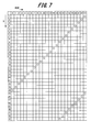
- FIG. 7 is an example of an explanatory diagram of a method for specifying a time zone in which measurement data cannot be acquired.
- the time when measurement data acquisition fails is, for example, 16:00.
- the measurement data acquisition failure time period in the example of FIG. Time zone. Then, when acquiring measurement data or retrying in the future, the acquisition of measurement data is skipped only in the time zone in which the acquisition of measurement data fails, and in the example of Example 1, only in the time zone of the collection timing 52 shown in FIG. To do. Thereby, an increase in energy loss due to failure in data collection can be suppressed.
- the second embodiment is an example of avoiding (canceling) a retry in a time zone in which measurement data cannot be obtained for the wireless slave station 13 that has failed to collect data.
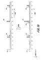
- FIG. 8 is an example of a timing diagram for explaining the operation of the automatic inspection system according to the second embodiment.
- the data collection device 15 succeeds in acquiring the measurement data from the accumulated data in the error recording unit 152 until some cause (for example, the influence of reflection from the western sun, etc.) is removed even when retrying is performed more than once. Judgment is unlikely.
- the data collection device 15 always fails in data collection for the wireless slave station 13 that has failed to acquire measurement data and has determined that the possibility of successful data collection is low until the cause of the failure is removed.
- Retry at the collection timing 52 that is, a time zone during which measurement data cannot be acquired
- mobile_unit 13 which failed in acquisition of measurement data can be reduced.
- FIG. 9 is an example of an operation explanatory diagram of the automatic inspection system according to the second embodiment.
- the data collection device 15 determines that data collection failures frequently occur in the wireless slave station 13_1 at the data collection timing (collection timing 52 shown in FIG. 8) of this regular period. Then, the data collection device 15 saves the response 34 of the wireless slave station 13_2 that has not failed to acquire measurement data in the inspection recording unit 151, and returns an error about the response 32 of the wireless slave station 13_1 that has failed to acquire measurement data. Saved in the recording unit 152.
- the data collection device 15 refers to the accumulated data in the error recording unit 152, and if data collection failures frequently occur at the data collection timing of this fixed cycle, the data collection device 15 requests the wireless slave station 13_1 to transmit data. 35 is stopped, and the retry of obtaining the measurement data for the wireless slave station 13_1 is not performed. Thereby, since the retry with respect to the wireless slave station 13_1 is skipped, it is possible to reduce energy loss due to data collection failure in the wireless slave station 13 that has failed to acquire measurement data.
- the third embodiment is an example in which the data collection plan is changed for the wireless slave station 13 that has failed to collect data.
- FIG. 10 is an example of a timing diagram for explaining the operation of the automatic inspection system according to the third embodiment.
- the data collection device 15 changes the data collection plan and performs measurement data acquisition when it is expected that measurement data acquisition at a fixed cycle will fail. Specifically, it is changed to a collection timing 54 that is, for example, one hour earlier than the collection timing 52 that always fails in data collection (one hour ahead). Thereby, in the wireless slave station 13 that has failed to acquire measurement data, the possibility of failure in acquisition of measurement data can be reduced, so that energy loss due to failure in data collection can be reduced.
- FIG. 11 is an example of an operation explanatory diagram of the automatic inspection system according to the third embodiment.
- the data collection device 15 determines that data collection failures frequently occur in the wireless slave station 13_1 at the data collection timing (collection timing 52 shown in FIG. 10) of this fixed period. Then, the data collection device 15 refers to the accumulated data in the error recording unit 152, and if data collection failures frequently occur at the data collection timing of this fixed cycle, the fixed-cycle data collection plan for the wireless slave station 13_1 To change.
- the data collection device 15 instructs the wireless master station 11 to collect data from the wireless slave station 13_1 according to the collection schedule based on the changed data collection plan.
- the wireless master station 11 transmits a data transmission request 31 to the wireless slave station 13_1.
- the transmission timing of the request 31 from the wireless master station 11 to the wireless slave station 13_1 is changed with the change of the data collection plan.
- the data collection plan is changed for the wireless slave station 13_1 in which measurement data acquisition failures frequently occur, and the measurement data is collected at an acquisition timing 54 different from the original collection timing 52, for example, one hour earlier. By performing the acquisition, it is possible to reduce energy loss due to failure in data collection.
- SYMBOLS 1 Multihop wireless network, 2 ... Network, 3 ... Aggregation server, 4 (4_1-4_n) ... Measuring instrument, 10 ... Automatic inspection system, 11 (11_1-11_k) ... Radio
Landscapes
- Engineering & Computer Science (AREA)
- Computer Networks & Wireless Communication (AREA)
- Signal Processing (AREA)
- Physics & Mathematics (AREA)
- General Physics & Mathematics (AREA)
- Arrangements For Transmission Of Measured Signals (AREA)
- Mobile Radio Communication Systems (AREA)
- Selective Calling Equipment (AREA)
Abstract
An automatic inspection system including a wireless slave unit having a reading device for acquiring the physical quantity of an object to be inspected and a wireless master unit for receiving the measured data of the physical quantity from the wireless slave unit, the automatic inspection system being provided with a data collection device for collecting measured data from the wireless slave unit via the wireless master unit in a fixed cycle and detecting a time slot from the result of data collection in which the measured data by the reading device cannot be acquired. On the basis of the result of detecting an unacquirable time slot, the wireless master unit exercises control on the wireless slave unit for avoiding recollection of the measured data in the unacquirable time slot.
Description
本発明は、自動点検システムおよび自動点検方法に関する。
The present invention relates to an automatic inspection system and an automatic inspection method.
発電所やプラント等の現場設備には、例えば配管を流れる水量などの物理量を計測する計測器(例えば、針式メータ)が多数設けられている。これらの計測器は、一日に数回程度あるいはそれ以上の周期で人間の目視による設備点検に用いられてきた。しかし、保守・点検業務では、点検作業員の高齢化や人員確保などが課題となってきている。
In field facilities such as power plants and plants, a number of measuring instruments (for example, needle meters) that measure physical quantities such as the amount of water flowing through piping are provided. These measuring instruments have been used for equipment inspection by human eyes at intervals of several times a day or more. However, in maintenance and inspection work, aging of inspection workers and securing of personnel are becoming issues.
このような観点から、計測器の表示部をカメラで撮像し、その撮影して画像データを無線ネットワークを経由して伝送するシステムが開発され、点検業務の自動化が図られている(例えば、特許文献1参照)。特許文献1には、「監視テレビカメラを使った画像処理において、メータ類の指針の位置を正確に読み取るのに好適な画像処理によるメータの読取り方法に関する。」と記載されている。
From this point of view, a system has been developed in which a display unit of a measuring instrument is imaged with a camera, and the image is captured and transmitted via a wireless network, thereby automating inspection work (for example, patents). Reference 1). Japanese Patent Application Laid-Open No. 2004-228561 describes that “in the image processing using a surveillance television camera, relates to a meter reading method by image processing suitable for accurately reading the position of the pointer of the meters”.
また、無線通信網を用いた無線検針システムにおいて、携帯型親機と無線子局(無線子機)との間の通信が失敗した際に、無線親局における通信のリトライ(再送)を行うことにより、通信時間の増加を抑制する技術がある(例えば、特許文献2参照)。特許文献2には、「携帯型親機は、無線子局に対して一括検針要求電文を送信するとともに、一括検針要求電文に対する応答電文を無線子局それぞれから受信する。携帯型親機は、応答電文を受信できなかった無線子局ごとにその通信失敗時に失敗原因別に分類判定し、分類別の一括通信でリトライ(再送)する。」と記載されている。
Also, in a wireless meter reading system using a wireless communication network, when communication between a portable master unit and a wireless slave station (wireless slave unit) fails, communication retry (retransmission) at the wireless master station is performed. Thus, there is a technique for suppressing an increase in communication time (see, for example, Patent Document 2). Patent Document 2 states that “a portable base unit transmits a batch meter reading request message to a wireless slave station and receives a response message for the batch meter reading request message from each of the wireless slave stations. For each wireless slave station that has failed to receive a response message, classification is determined according to the cause of failure when communication fails, and retry (retransmission) is performed by batch communication according to classification.
特許文献1には、画像解析により流量計などのメータ指針位置を読み取る技術が開示されている。特許文献2には、通信のリトライによる通信時間の増加を抑制する技術が開示されている。しかしながら、特許文献1および特許文献2に記載の従来技術では、物理量を計測する読取装置にて計測の可否が発生し得る状況下での実運用を踏まえたエネルギーロスの低減、即ちネットワークの低消費電力化については考慮されていない。
Patent Document 1 discloses a technique for reading the position of a meter pointer such as a flow meter by image analysis. Patent Document 2 discloses a technique for suppressing an increase in communication time due to communication retry. However, in the prior art described in Patent Document 1 and Patent Document 2, energy loss is reduced based on actual operation under a situation in which measurement is possible in a reading device that measures physical quantities, that is, low network consumption. Electricity is not considered.
本発明は、無線親局と無線子局との間で無線ネットワークを用いて通信を行うにあたって、ネットワークの低消費電力化を実現できる自動点検システムおよび自動点検方法を提供することを目的とする。
An object of the present invention is to provide an automatic inspection system and an automatic inspection method capable of realizing low power consumption of a network when communication is performed between a wireless master station and a wireless slave station using a wireless network.
上記目的を達成するために、本発明の自動点検システムは、
点検対象の物理量を取得する読取装置を有する無線子機と、読取装置で取得した物理量の計測データを、無線子機から無線通信にて受信する無線親機とを含む無線ネットワークを用いた自動点検システムである。
そして、計測データを一定周期で無線子機から無線親機を経由して収集し、その収集結果から読取装置による計測データの取得不可能な時間帯を検出するデータ収集装置を備える。無線親機は無線子機に対して、取得不可能な時間帯の検出結果に基づいて、取得不可能な時間帯での計測データの再取得を回避する制御を行う
ことを特徴とする。 In order to achieve the above object, the automatic inspection system of the present invention provides:
Automatic inspection using a wireless network including a wireless slave device having a reading device for acquiring a physical quantity to be inspected and a wireless parent device for receiving physical quantity measurement data acquired by the reading device from the wireless slave device by wireless communication System.
A data collection device is provided that collects measurement data from a wireless slave device via a wireless master device at a fixed period and detects a time zone during which measurement data cannot be acquired by the reading device from the collection result. The wireless master unit controls the wireless slave unit to avoid re-acquisition of measurement data in an unacquirable time zone based on a detection result of an unacquireable time zone.
また、本発明の自動点検方法は、
点検対象の物理量を取得する読取装置を有する無線子機と、読取装置で取得した物理量の計測データを、無線子機から無線通信にて受信する無線親機とを含む無線ネットワークを用いた自動点検方法である。
そして、計測データを一定周期で無線子機から無線親機を経由して収集し、その収集結果から読取装置の取得不可能な時間帯を検出し、取得不可な時間帯の検出結果に基づいて、無線親機から無線子機に対して、取得不可能な時間帯での計測データの再取得を回避する
ことを特徴とする。 The automatic inspection method of the present invention is
Automatic inspection using a wireless network including a wireless slave device having a reading device for acquiring a physical quantity to be inspected and a wireless parent device for receiving physical quantity measurement data acquired by the reading device from the wireless slave device by wireless communication Is the method.
Then, the measurement data is collected from the wireless slave device via the wireless master device at a fixed period, and the reading device's unacquirable time zone is detected from the collection result, and based on the non-obtainable time zone detection result The wireless master unit avoids re-acquisition of measurement data in a time zone that cannot be acquired from the wireless slave unit.
本発明によれば、取得不可能な時間帯での計測データの再取得を回避することで、再取得に起因するエネルギーロスを抑えることができるため、ネットワークの低消費電力化を実現できる。
According to the present invention, energy loss caused by re-acquisition can be suppressed by avoiding re-acquisition of measurement data in an unacquirable time zone, so that low power consumption of the network can be realized.
以下、本発明を実施するための形態(以下、「実施形態」と記述する)について図面を用いて詳細に説明する。本発明は実施形態に限定されるものではない。なお、以下の説明や各図において、同一要素又は同一機能を有する要素には同一符号を用いることとし、重複する説明は省略する。
Hereinafter, modes for carrying out the present invention (hereinafter referred to as “embodiments”) will be described in detail with reference to the drawings. The present invention is not limited to the embodiment. In the following description and each drawing, the same reference numerals are used for the same elements or elements having the same functions, and duplicate descriptions are omitted.
本発明では、無線子局と無線親局とを含む無線ネットワークとして、好ましくは、マルチホップ無線ネットワーク(マルチホップによるセンサ無線ネットワーク)を用いて、点検対象の物理量を計測する計測器の点検の自動化を図る。マルチホップ無線ネットワークは、複数の無線端末がそれぞれ隣接する他の無線端末同士を経由して、いわゆるバケツリレー方式にてデータを伝送する無線ネットワークである。点検対象の物理量を計測する計測器としては、流量計、電力計、電流計、圧力計、温度計などのメータ(例えば、針式メータ)を例示することができる。
In the present invention, it is preferable to use a multi-hop wireless network (a multi-hop sensor wireless network) as a wireless network including a wireless slave station and a wireless master station, and to automate the inspection of a measuring instrument that measures the physical quantity to be inspected. Plan. A multi-hop wireless network is a wireless network in which a plurality of wireless terminals transmit data using a so-called bucket relay system via other wireless terminals adjacent to each other. Examples of the measuring instrument that measures the physical quantity to be inspected include meters such as a flow meter, a wattmeter, an ammeter, a pressure gauge, and a thermometer (for example, a needle meter).
[マルチホップ無線ネットワーク]
ここで、マルチホップ無線ネットワークの基本的な構成の概要について、図1を用いて説明する。図1は、マルチホップ無線ネットワークの基本的な構成の概要を示すシステム構成図の例である。 [Multi-hop wireless network]
Here, an outline of a basic configuration of the multi-hop wireless network will be described with reference to FIG. FIG. 1 is an example of a system configuration diagram showing an outline of a basic configuration of a multi-hop wireless network.
本例に係るマルチホップ無線ネットワーク1は、基地局としてk個の無線親局11_1~11_k(以下、代表して「無線親局11」と記述する場合がある)を備えている。これらの無線親局11_1~11_kは、ネットワーク2を経由して集約サーバ3に接続されている。ネットワーク2に対する無線親局11_1~11_kの接続形態については、特に限定されるものではなく、有線接続であってもよいし、無線接続であってもよい。
The multi-hop wireless network 1 according to the present example includes k wireless master stations 11_1 to 11_k (hereinafter sometimes referred to as “wireless master station 11” as representative) as base stations. These wireless master stations 11_1 to 11_k are connected to the aggregation server 3 via the network 2. The connection form of the wireless master stations 11_1 to 11_k to the network 2 is not particularly limited, and may be wired connection or wireless connection.
無線親局11_1~11_kに対して、中継局としてm個の無線子局12_1~12_m(以下、代表して「無線子局12」と記述する場合がある)が設けられている。さらに、端末局(末端の階層の子局)としてn個の無線子局13_1~13_n(以下、代表して「無線子局13」と記述する場合がある)が設けられている。すなわち、無線親局11_1~11_kが末端の階層の無線子局13_1~13_nと通信する場合は、その途中に位置する無線子局12_1~12_mが中継局として機能する。例えば、ある一つの無線親局11_1が、ある一つの無線子局13_2と通信する場合、マルチホップ無線ネットワーク1上の途中に位置する無線子局(本例の場合、無線子局12_1)が中継局となって通信が行われる。
The wireless master stations 11_1 to 11_k are provided with m wireless slave stations 12_1 to 12_m (hereinafter, may be described as “wireless slave stations 12” representatively) as relay stations. Further, n wireless slave stations 13_1 to 13_n (hereinafter sometimes referred to as “wireless slave stations 13” as representative) are provided as terminal stations (child stations in the terminal hierarchy). That is, when the radio master stations 11_1 to 11_k communicate with the radio slave stations 13_1 to 13_n at the end hierarchy, the radio slave stations 12_1 to 12_m located in the middle function as relay stations. For example, when a certain wireless master station 11_1 communicates with a certain wireless slave station 13_2, a wireless slave station located in the middle of the multi-hop wireless network 1 (in this example, the wireless slave station 12_1) relays. Communication is performed as a station.
そして、マルチホップ無線ネットワーク1を用いた自動点検システムにあっては、末端の無線子局13_1~13_nの各々が、点検対象の物理量を計測する計測器4_1~4_n(以下、代表して「計測器4」と記述する場合がある)の計測値を取得する読取装置14_1~14_n(以下、代表して「読取装置14」と記述する場合がある)を備えている。計測器4_1~4_nとしては、水や液体などの流量を計測する流量計や、電力量を計測する電力計などのメータを例示することができる。
In the automatic inspection system using the multi-hop wireless network 1, each of the terminal wireless slave stations 13_1 to 13_n measures the measuring devices 4_1 to 4_n (hereinafter, representatively “measurement” Reading devices 14_1 to 14_n (hereinafter, may be described as “reading device 14” as a representative). Examples of the measuring instruments 4_1 to 4_n include meters such as a flow meter that measures the flow rate of water or liquid and a wattmeter that measures the amount of electric power.
読取装置14_1~14_nとしては、例えば、CCD(Charge Coupled Device)イメージセンサやCMOS(Complementary Metal Oxide Semiconductor)イメージセンサ等の固体撮像素子を撮像デバイスとして用いたカメラを用いることができる。この場合、読取装置14_1~14_nは、カメラが計測器4_1~4_nを撮影した画像から計測器4_1~4_nの計測値を読み取ることになる。ただし、読取装置14_1~14_nとしては、カメラに限られるものではない。例えば、計測器4_1~4_nに連動して点検対象の物理量を電流や電圧等の電気信号に変換して計測する計器など、点検対象の物理量を計測できるものであればよい。
As the reading devices 14_1 to 14_n, for example, a camera using a solid-state imaging device such as a CCD (Charge-Coupled Device) image sensor or a CMOS (Complementary Metal-Oxide Semiconductor) image sensor as an imaging device can be used. In this case, the reading devices 14_1 to 14_n read the measurement values of the measuring instruments 4_1 to 4_n from the images obtained by the cameras capturing the measuring instruments 4_1 to 4_n. However, the reading devices 14_1 to 14_n are not limited to cameras. For example, any instrument that can measure the physical quantity to be inspected may be used, such as a meter that converts the physical quantity to be inspected into an electrical signal such as current or voltage in conjunction with the measuring instruments 4_1 to 4_n.
末端の無線子局13_1~13_nは、読取装置14_1~14_nが取得した計測器4_1~4_nの計測結果を、マルチホップ無線ネットワーク1上の途中に位置する中継局である無線子局12_1~12_mを経由して無線親局11_1~11_kに送信する。
The terminal wireless slave stations 13_1 to 13_n send the measurement results of the measuring instruments 4_1 to 4_n acquired by the readers 14_1 to 14_n to the wireless slave stations 12_1 to 12_m that are relay stations located in the middle of the multi-hop wireless network 1. Via the wireless master stations 11_1 to 11_k.
本例では、無線子局として、中継局と端末局の2層の階層構造を例示したが、2層に限られるものではなく、3層以上の階層構造とすることもできる。そして、無線親局が末端の階層の無線子局と通信するとき、上述したように、マルチホップ無線ネットワーク1上の途中に位置する複数の無線子局が中継局として機能する。このとき、通信相手の末端の階層の無線子局だけでなく、その途中の複数の無線子局も起動されて電力を消費することになる。
In this example, a two-layer hierarchical structure of a relay station and a terminal station is illustrated as a wireless slave station. However, the hierarchical structure is not limited to two layers, and may be a three-layer or higher layer structure. When the wireless master station communicates with the wireless slave station in the terminal hierarchy, as described above, a plurality of wireless slave stations located in the middle of the multi-hop wireless network 1 function as relay stations. At this time, not only the wireless slave stations at the end of the communication partner, but also a plurality of wireless slave stations in the middle are activated and consume power.
上述したマルチホップ無線ネットワーク1は、無線端末の間を次々とデータを移動させることで、1つのデータ収集局(無線親局11または集約サーバ3)でカバーできる通信範囲を広げることができる利点がある。また、電波環境の悪い領域を回避するようにマルチホップの中継経路を設定することで、電波の不感地帯を解消することができるため、データ伝送の高信頼性に貢献できる利点もある。
The multihop wireless network 1 described above has the advantage that the communication range that can be covered by one data collection station (wireless master station 11 or aggregation server 3) can be expanded by moving data one after another between wireless terminals. is there. In addition, by setting a multi-hop relay path so as to avoid an area where the radio wave environment is bad, the dead zone of the radio wave can be eliminated, and there is an advantage that it can contribute to high reliability of data transmission.
マルチホップ無線ネットワーク1において、外部から給電が困難な場所に無線子局13や読取装置14を設置する場合がある。このような場合には、無線子局13や読取装置14の電源として、電池等の自立電源を用いることになる。何故なら、給電が困難な場所に設置した無線子局13の電源として商用電源を用いるとした場合、給電線を長い距離に亘って配線したり、コンセントを設置したりするなど電気設備にコストがかかり、マルチホップ無線ネットワーク1としてコストが高くなるためである。
In the multi-hop wireless network 1, the wireless slave station 13 and the reader 14 may be installed in a place where it is difficult to supply power from the outside. In such a case, a self-supporting power source such as a battery is used as a power source for the wireless slave station 13 and the reading device 14. This is because, when a commercial power source is used as the power source of the wireless slave station 13 installed in a place where power feeding is difficult, the cost of the electrical equipment such as wiring the power feeding line over a long distance or installing an outlet is increased. This is because the cost of the multi-hop wireless network 1 increases.
このように、特に無線子局13や読取装置14の電源として自立電源を用いるマルチホップ無線ネットワーク1にあっては、電池等の自立電源で無線子局13や読取装置14を長時間に亘って動作させるためには、マルチホップ無線ネットワーク1の低消費電力化が望まれる。ただし、マルチホップ無線ネットワーク1の低消費電力化は、無線端末を自立電源で動作させる場合に限られる技術課題ではない。
As described above, in particular, in the multi-hop wireless network 1 using an independent power source as the power source of the wireless slave station 13 and the reading device 14, the wireless slave station 13 and the reading device 14 are held for a long time with an independent power source such as a battery. In order to operate, low power consumption of the multi-hop wireless network 1 is desired. However, the reduction in power consumption of the multi-hop wireless network 1 is not a technical problem limited to the case where the wireless terminal is operated by an independent power source.
ところで、マルチホップ無線ネットワーク1において、無線親局11が末端の無線子局13と通信を行う場合、複数の無線子局13をホップ(パケット単位での受信と送信による伝送)させた通信動作を行うことになる。したがって、無線子局13の消費電力を抑えるためには、特にホップ数(無線親局11に到達するまでに経由する中継局の数)の多い末端の無線子局13との通信の頻度は少ない方が好ましい(有利である)。
By the way, in the multi-hop wireless network 1, when the wireless master station 11 communicates with the terminal wireless slave station 13, a communication operation in which a plurality of wireless slave stations 13 are hopped (transmission by reception and transmission in packet units) is performed. Will do. Therefore, in order to suppress the power consumption of the wireless slave station 13, the frequency of communication with the terminal wireless slave station 13 having a large number of hops (the number of relay stations that pass through until reaching the wireless master station 11) is particularly low. Is preferred (advantageous).
一方、無線親局11と無線子局13との間でマルチホップ無線ネットワーク1を介してデータの伝送を行う際に、ある無線子局13において、読取装置14による計測器4の計測値の取得に失敗する場合がある。一例として、読取装置14がカメラによる撮影によって計測器4の計測値を取得する場合、例えば、結露、雨天、西日による反射などの影響によって、適切な画像を撮影できない環境下では、読取装置14による計測器4の計測値の取得に失敗する場合がある。
On the other hand, when data is transmitted between the wireless master station 11 and the wireless slave station 13 via the multi-hop wireless network 1, the measurement value of the measuring instrument 4 is acquired by the reader 14 in a certain wireless slave station 13. May fail. As an example, when the reading device 14 acquires the measurement value of the measuring instrument 4 by photographing with a camera, for example, in an environment where an appropriate image cannot be photographed due to the influence of condensation, rainy weather, reflection from the sun, etc. The measurement value of the measuring instrument 4 may fail to be acquired.
このように、読取装置14による計測器4の計測値の取得に失敗した場合、計測値の取得の再試行(再取得/リトライ)が行われることになる。このリトライを行う際、読取装置14による計測値の再取得(再計測)を行うこととなる。したがって、自立電源のエネルギーロスを低減するためには、計測器4の計測値を再取得するリトライ回数は少ない方が好ましい(有利である)。
In this way, when the reading device 14 fails to acquire the measurement value of the measuring instrument 4, the measurement value acquisition is retried (re-acquisition / retry). When this retry is performed, re-acquisition (re-measurement) of the measurement value by the reading device 14 is performed. Therefore, in order to reduce the energy loss of the stand-alone power supply, it is preferable (advantageous) that the number of retries for reacquiring the measurement value of the measuring instrument 4 is small.
また、読取装置14による計測器4の計測値の取得が何らかの要因(例えば、西日による反射等)によって失敗した場合、当該要因が直ちに解消される可能性が低い。したがって、無線親局11から無線子局13に対して、直ちにリトライの要求を出してしまうと、中継局としても動作する無線子局12を含めて通信の往復が新たに発生するため、無線ネットワーク全体にエネルギーロスの増大が波及する。加えて、計測値の取得エラーによるリトライが頻発し、読取装置14によるエネルギーロスが増大する。
In addition, when the acquisition of the measurement value of the measuring instrument 4 by the reading device 14 fails due to some factor (for example, reflection by the western sun), there is a low possibility that the factor is immediately eliminated. Accordingly, if a request for retry is immediately issued from the wireless master station 11 to the wireless slave station 13, a new round trip of communication including the wireless slave station 12 that also operates as a relay station occurs. The increase in energy loss will spread throughout. In addition, retries due to measurement value acquisition errors occur frequently, and energy loss due to the reading device 14 increases.
ところで、末端の無線子局13は、通常、省電力モードであるスリープ状態におかれており、データ転送時や読取装置14による計測器4の計測値の取得動作時にのみ起動される。しかし、計測値の取得エラーによるリトライが頻発すると、無線子局13において、リトライのたびに起動/停止が繰り返されることになるため、その分だけ電力が消費される。換言すれば、本来、スリープ状態にあって電力が消費されない期間において、リトライのたびに起動/停止が繰り返されることで、無線子局13がスリープ状態にある期間が短くなり、消費電力が増大する。
By the way, the terminal wireless slave station 13 is normally in a sleep state, which is a power saving mode, and is activated only when data is transferred or when the reading value of the measuring instrument 4 is acquired by the reading device 14. However, if retries due to measurement value acquisition errors occur frequently, the wireless slave station 13 is repeatedly started / stopped each time it is retried, so that much power is consumed. In other words, in a period in which power is not consumed in the sleep state originally, the start / stop is repeated for each retry, so that the period in which the wireless slave station 13 is in the sleep state is shortened and power consumption is increased. .
[本発明の実施形態]
上述したように、無線ネットワークの一例であるマルチホップ無線ネットワーク1、特に無線子局13や読取装置14の電源として電池等の自立電源を用いるマルチホップ無線ネットワーク1にあっては、低消費電力化が望まれる。そこで、本発明の実施形態では、読取装置14による計測データ(計測値)の取得エラーに伴うリトライ(再取得)を、計測データの取得不可能な時間帯では回避し、リトライに起因するエネルギーロスを低減することにより、ネットワークの低消費電力化を実現する。 Embodiment of the present invention
As described above, in themulti-hop wireless network 1 that is an example of the wireless network, particularly in the multi-hop wireless network 1 that uses an independent power source such as a battery as a power source for the wireless slave station 13 and the reader 14, low power consumption is achieved. Is desired. Therefore, in the embodiment of the present invention, retry (re-acquisition) due to an acquisition error of measurement data (measurement value) by the reading device 14 is avoided in a time zone in which measurement data cannot be acquired, and energy loss caused by the retry is performed. By reducing the above, low power consumption of the network is realized.
上述したように、無線ネットワークの一例であるマルチホップ無線ネットワーク1、特に無線子局13や読取装置14の電源として電池等の自立電源を用いるマルチホップ無線ネットワーク1にあっては、低消費電力化が望まれる。そこで、本発明の実施形態では、読取装置14による計測データ(計測値)の取得エラーに伴うリトライ(再取得)を、計測データの取得不可能な時間帯では回避し、リトライに起因するエネルギーロスを低減することにより、ネットワークの低消費電力化を実現する。 Embodiment of the present invention
As described above, in the
以下に、マルチホップ無線ネットワーク1を用いて、計測器4_1~4_nの点検を自動的に行う自動点検システムにおいて、計測データの取得不可能な時間帯での取得エラーに伴う再取得(リトライ)を回避することによって、マルチホップ無線ネットワーク1の低消費電力化を実現する本発明の実施形態について具体的に説明する。
Below, in the automatic inspection system that automatically checks the measuring instruments 4_1 to 4_n using the multi-hop wireless network 1, re-acquisition (retries) due to an acquisition error in a time zone when measurement data cannot be acquired. An embodiment of the present invention that achieves a reduction in power consumption of the multi-hop wireless network 1 by avoiding this will be specifically described.
図2は、本発明の実施形態に係る自動点検システムの要部の構成を示すブロック図の例である。本実施形態では、計測器4(4_1~4_n)として、針と文字盤(目盛り盤)によって物理量を計測する針式メータを用いることができる。ただし、針式メータに限られるものではない。
FIG. 2 is an example of a block diagram showing a configuration of a main part of the automatic inspection system according to the embodiment of the present invention. In the present embodiment, as the measuring instrument 4 (4_1 to 4_n), a needle meter that measures a physical quantity using a needle and a dial (scale board) can be used. However, it is not limited to a needle type meter.
図2には、ある一つの基地局である無線親局11(11_1~11_k)と、ある一つの端末局である無線子局13(13_1~13_n)との間で通信を行う場合のシステム構成について模式的に図示している。そして、理解を容易にするために、無線親局11と無線子局13との間に介在する中継局(図1の無線子局12_1~12_m)については図示を省略している。
FIG. 2 shows a system configuration in which communication is performed between a wireless master station 11 (11_1 to 11_k) that is a certain base station and a wireless slave station 13 (13_1 to 13_n) that is a certain terminal station. Is schematically illustrated. In order to facilitate understanding, the relay stations (wireless slave stations 12_1 to 12_m in FIG. 1) interposed between the wireless master station 11 and the wireless slave station 13 are not shown.
図2に示すように、本実施形態に係る自動点検システム10は、無線子局13が読取装置14を備えていることに加えて、無線親局11がデータ収集装置15を備える構成となっている。無線親局11に対するデータ収集装置15の接続形態については、特に限定されるものではなく、有線接続であってもよいし、無線接続であってもよい。同様に、無線子局13に対する読取装置14の接続形態についても、特に限定されるものではなく、有線接続であってもよいし、無線接続であってもよい。
As shown in FIG. 2, the automatic inspection system 10 according to the present embodiment has a configuration in which the wireless master station 11 includes a data collecting device 15 in addition to the wireless slave station 13 including the reading device 14. Yes. The connection form of the data collection device 15 with respect to the wireless master station 11 is not particularly limited, and may be wired connection or wireless connection. Similarly, the connection form of the reading device 14 to the wireless slave station 13 is not particularly limited, and may be wired connection or wireless connection.
なお、ここでは、データ収集装置15を無線親局11の位置に配置する場合を例示したが、この限りでない。すなわち、ユーザが無線親局11の位置でデータ収集を行う場合には、データ収集装置15を無線親局11の位置に配置するようにすればよいし、ユーザが図1に示す集約サーバ3の位置でデータ収集を行う場合には、データ収集装置15を集約サーバ3の位置に配置するようにすればよい。
In addition, although the case where the data collection device 15 is arranged at the position of the wireless master station 11 is illustrated here, this is not restrictive. In other words, when the user collects data at the position of the wireless master station 11, the data collection device 15 may be arranged at the position of the wireless master station 11, and the user may use the aggregation server 3 shown in FIG. When collecting data at a position, the data collecting device 15 may be arranged at the position of the aggregation server 3.
図2において、実線の矢印は、無線親局11から無線子局13に送信されるデータ送信の要求21を示し、破線の矢印は、無線親局11からの要求21に対して無線子局13から無線親局11に送信される応答22を示している。この応答22には、読取装置14による計測器4の計測値の取得エラーの要因も含まれる。
In FIG. 2, the solid arrow indicates the data transmission request 21 transmitted from the wireless master station 11 to the wireless slave station 13, and the broken arrow indicates the wireless slave station 13 in response to the request 21 from the wireless master station 11. The response 22 transmitted from the wireless master station 11 is shown. The response 22 includes a cause of an error in obtaining the measurement value of the measuring instrument 4 by the reading device 14.
読取装置14は、流量計、電力計、電流計、圧力計、温度計などの計測器4の計測値を読み取る(取得する)装置である。読取装置14は、例えば、マイクロプロセッサ、メモリ、入出力部、電池(いずれも不図示)などのハードウェア資源を有する電子回路装置として構成されている。読取装置14は、例えば、計測用センサ141およびセンサ情報解析部142を備えている。
The reading device 14 is a device that reads (acquires) a measurement value of the measuring device 4 such as a flow meter, a power meter, an ammeter, a pressure meter, and a thermometer. The reading device 14 is configured as an electronic circuit device having hardware resources such as a microprocessor, a memory, an input / output unit, and a battery (all not shown). The reading device 14 includes, for example, a measurement sensor 141 and a sensor information analysis unit 142.
計測用センサ141は、例えばイメージセンサからなり、計測器4を撮影して得た画像データを出力し、センサ情報解析部142に供給する。ただし、計測用センサ141としては、イメージセンサに限定されるものではなく、点検対象の物理量を読み取ることができる構成のものであればその種類(形式)は問わない。センサ情報解析部142は、計測用センサ141から供給される画像データを解析(データ分析)することによって計測器4の計測値を読み取る。
The measurement sensor 141 is composed of, for example, an image sensor, outputs image data obtained by photographing the measuring instrument 4, and supplies the image data to the sensor information analysis unit 142. However, the measurement sensor 141 is not limited to an image sensor, and the type (form) of the measurement sensor 141 is not limited as long as it is configured to be able to read the physical quantity to be inspected. The sensor information analysis unit 142 reads the measurement value of the measuring instrument 4 by analyzing (data analysis) the image data supplied from the measurement sensor 141.
無線子局13は、読取装置14で読み取った計測器4の計測値を計測データとして無線親局11に送信するとともに、センサ情報解析部142でのデータ分析結果を示す応答22を無線親局11に送信する。この無線子局13から無線親局11への応答22には、センサ情報解析部142でのデータ分析に失敗がない応答や、データ分析に失敗した応答または計測用センサ141から計測値を受信できなかった応答が含まれる。
The wireless slave station 13 transmits the measurement value of the measuring instrument 4 read by the reading device 14 to the wireless master station 11 as measurement data, and sends a response 22 indicating the data analysis result in the sensor information analysis unit 142 to the wireless master station 11. Send to. The response 22 from the wireless slave station 13 to the wireless master station 11 can receive a response that does not fail in data analysis in the sensor information analysis unit 142, a response that fails in data analysis, or a measurement value from the measurement sensor 141. Contains the response that did not exist.
データ収集装置15は、例えば、マイクロプロセッサ、メモリ、補助記憶装置、入出力部(いずれも不図示)などのハードウェア資源と、オペレーティングシステムおよびコンピュータプログラムなどのソフトウェア資源とを有する計算器または専用の電子回路装置として構成されている。データ収集装置15は、例えば、点検記録部151およびエラー記録部152を備えている。
The data collection device 15 is, for example, a computer having a hardware resource such as a microprocessor, a memory, an auxiliary storage device, and an input / output unit (all not shown) and a software resource such as an operating system and a computer program, or a dedicated computer It is configured as an electronic circuit device. The data collection device 15 includes, for example, an inspection recording unit 151 and an error recording unit 152.
データ収集装置15は、データ分析に失敗がない応答について点検記録部151に保存し、データ分析に失敗した応答または計測用センサ141から計測値を受信できなかった応答についてエラー記録部152に保存する。
The data collection device 15 stores in the inspection recording unit 151 responses that do not fail in data analysis, and stores in the error recording unit 152 responses that fail in data analysis or responses that have failed to receive measurement values from the measurement sensor 141. .
以下に、データ収集装置15でのデータ収集の処理について、図3のフローチャートに沿って説明する。図3は、データ収集装置15におけるデータ収集処理の流れを示すフローチャートの例である。なお、本処理は、次回の定周期処理を待つためループする処理となる。
Hereinafter, the data collection processing in the data collection device 15 will be described with reference to the flowchart of FIG. FIG. 3 is an example of a flowchart showing the flow of data collection processing in the data collection device 15. This process is a process that loops to wait for the next fixed-cycle process.
ここでは、データ収集装置15でのデータ収集の処理機能は、例えば、マイクロプロセッサがその機能を実現するプログラムを解釈し、実行することによって実現される場合を例に挙げて説明する。この場合、以下に説明する一連の処理は、マイクロプロセッサによる制御の下に実行されることになる。
Here, the data collection processing function in the data collection device 15 will be described by taking as an example a case where it is realized by, for example, a microprocessor interpreting and executing a program that realizes the function. In this case, a series of processing described below is executed under the control of the microprocessor.
マイクロプロセッサは、エラー記録部152の蓄積データ、即ちエラー記録に基づいた現在時刻での収集計画のセットを行い(ステップS11)、次いで収集計画がセットされているか否かを判断する(ステップS12)。ここで、収集計画がセットされていない場合は(S12のNO)、マイクロプロセッサは、ステップS11に戻って次回時刻の収集計画セットの実施まで待機する。
The microprocessor sets the collection plan at the current time based on the accumulated data of the error recording unit 152, that is, the error record (step S11), and then determines whether or not the collection plan is set (step S12). . If the collection plan is not set (NO in S12), the microprocessor returns to step S11 and waits until the next time collection plan is executed.
収集計画がセットされている場合は(S12のYES)、マイクロプロセッサは、セットされた収集計画に基づいて、無線親局11を経由して無線子局13に対してデータ収集の要求(図2の要求21)を送信する(ステップS13)。次に、マイクロプロセッサは、今回セットされた収集計画を消去し(ステップS14)、次いで無線子局13からの応答(図2の応答22)が正しく受信できたか否かを判断する(ステップS15)。
When the collection plan is set (YES in S12), the microprocessor requests the wireless slave station 13 to collect data based on the set collection plan (FIG. 2). Request 21) is transmitted (step S13). Next, the microprocessor erases the collection plan set this time (step S14), and then determines whether or not the response from the wireless slave station 13 (response 22 in FIG. 2) has been correctly received (step S15). .
マイクロプロセッサは、応答が正しく受信できている場合(S15のYES)、点検記録部151にデータ収集の記録を保存し(ステップS16)、しかる後ステップS11に戻る。応答が正しく受信できていない場合(S15のNO)、マイクロプロセッサは、エラー記録部152にデータ収集結果を保存する(ステップS17)。次に、マイクロプロセッサは、データ収集に失敗した無線子局13に対するデータ収集の再取得(リトライ)の要求が所定のリトライ回数を超過しているか否かを判断する(ステップS18)。
If the response is correctly received (YES in S15), the microprocessor stores the data collection record in the inspection recording unit 151 (step S16), and then returns to step S11. If the response has not been received correctly (NO in S15), the microprocessor stores the data collection result in the error recording unit 152 (step S17). Next, the microprocessor determines whether or not a request for reacquisition (retry) of data collection for the wireless slave station 13 that has failed in data collection has exceeded a predetermined number of retries (step S18).
そして、マイクロプロセッサは、所定のリトライ回数を超過していれば(S18のYES)、ステップS11に戻り、次回の定周期処理を待つことになる。また、所定のリトライ回数を超過していなければ(S18のNO)、マイクロプロセッサは、エラー記録部152の蓄積データに基づいたデータ収集のリトライ計画をセットし(ステップS19)、しかる後ステップS12に移行し、図2の応答22が正しく受信できていない無線子局13に対して再度データ収集の要求送信を実施する。
If the predetermined number of retries has been exceeded (YES in S18), the microprocessor returns to step S11 and waits for the next periodic processing. If the predetermined number of retries has not been exceeded (NO in S18), the microprocessor sets a data collection retry plan based on the accumulated data in the error recording unit 152 (step S19), and then proceeds to step S12. The data collection request is transmitted again to the wireless slave station 13 that has not correctly received the response 22 of FIG.
上述したように、データ収集装置15では、データ収集処理において、無線子局13からの応答(図2の応答22)が時間的に失敗している場合に応じて、システム的に読取装置14による計測データの再取得(リトライ)を行わないようにしている。これにより、マルチホップ無線ネットワーク1および本実施形態に係る自動点検システム10の消費電力を抑えることができる。
As described above, in the data collection device 15, in the data collection processing, the reading device 14 systematically responds when the response from the wireless slave station 13 (response 22 in FIG. 2) has failed in time. The measurement data is not reacquired (retry). Thereby, the power consumption of the multihop wireless network 1 and the automatic inspection system 10 according to the present embodiment can be suppressed.
続いて、上記構成の本実施形態に係る自動点検システム10の点検動作について、図4を用いて説明する。図4は、本実施形態に係る自動点検システム10の点検動作の説明に供する動作説明図の例である。ここでは一例として、一定周期でのデータ収集の処理対象を2つの無線子局13_1および無線子局13_2とし、無線子局13_1側ではセンサ情報解析部142でのデータ解析(データ取得)に失敗する場合を例に挙げて説明する。
Subsequently, the inspection operation of the automatic inspection system 10 according to this embodiment having the above-described configuration will be described with reference to FIG. FIG. 4 is an example of an operation explanatory diagram for explaining the inspection operation of the automatic inspection system 10 according to the present embodiment. Here, as an example, two wireless slave stations 13_1 and 13_2 are targeted for data collection at a fixed period, and data analysis (data acquisition) by the sensor information analysis unit 142 fails on the wireless slave station 13_1 side. A case will be described as an example.
データ収集装置15は、予め設定されている収集スケジュールに従い、無線親局11に対して読取装置14が取得する、計測・点検対象の計測器4の計測値のデータ収集を指示する。この指示を受けて、無線親局11は、無線子局13_1に対してデータ送信の要求31を送信する。この要求31を受けて、無線子局13_1は、読取装置14_1を起動し、計測用センサ141によるセンシングで得た計測器4の計測データの取得を試みる。このとき、センサ情報解析部142でのデータ解析に失敗したため、無線子局13_1は、読取装置14_1を停止し、しかる後データ解析に失敗した旨の応答32を無線親局11に送信する。
The data collecting device 15 instructs the wireless master station 11 to collect data of the measurement values of the measuring instrument 4 to be measured and inspected, which the reading device 14 acquires, according to a collection schedule set in advance. In response to this instruction, the wireless master station 11 transmits a data transmission request 31 to the wireless slave station 13_1. Upon receiving this request 31, the wireless slave station 13_1 activates the reading device 14_1 and attempts to acquire measurement data of the measuring instrument 4 obtained by sensing by the measurement sensor 141. At this time, since the data analysis by the sensor information analysis unit 142 has failed, the wireless slave station 13_1 stops the reading device 14_1, and then transmits a response 32 indicating that the data analysis has failed to the wireless master station 11.
次に、データ収集装置15からのデータ収集の指示を受けて、無線親局11は、無線子局13_2に対してデータ送信の要求33を送信する。この要求33を受けて、無線子局13_2は、読取装置14_2を起動し、計測用センサ141によるセンシングで得た計測器4の計測データを取得する。そして、無線子局13_2は、読取装置14_2を停止し、しかる後計測データを含めた応答34を無線親局11に送信する。
Next, in response to the data collection instruction from the data collection device 15, the wireless master station 11 transmits a data transmission request 33 to the wireless slave station 13_2. In response to this request 33, the wireless slave station 13_2 activates the reading device 14_2 and acquires measurement data of the measuring instrument 4 obtained by sensing by the measurement sensor 141. The wireless slave station 13_2 then stops the reading device 14_2, and then transmits a response 34 including the measurement data to the wireless master station 11.
無線親局11は、無線子局13_1からの応答32および無線子局13_2からの応答34を受信すると、その受信結果をデータ収集装置15に供給(送信)する。すると、データ収集装置15は、データ解析(データ取得)に失敗がない無線子局13_2からの応答34について点検記録部151に保存し、データ解析に失敗した無線子局13_1からの応答32についてエラー記録部152に保存する。
When receiving the response 32 from the wireless slave station 13_1 and the response 34 from the wireless slave station 13_2, the wireless master station 11 supplies (transmits) the reception result to the data collection device 15. Then, the data collection device 15 stores the response 34 from the wireless slave station 13_2 that has not failed in data analysis (data acquisition) in the inspection recording unit 151, and an error occurs in the response 32 from the wireless slave station 13_1 that has failed in data analysis. Saved in the recording unit 152.
また、データ収集装置15は、データ収集に失敗した無線子局13_1に対して、計測データの取得を再度実施(再試行)するように、無線親局11に計測データの再取得(リトライ)を指示する。この指示を受けて、無線親局11は、前回データ収集に失敗した無線子局13_1に対してデータ送信の要求35を送信する。この要求35を受けて、無線子局13_1は、読取装置14_1を起動し、計測器4の計測データの取得を行う。
Further, the data collection device 15 causes the wireless master station 11 to re-acquire the measurement data (retry) so that the wireless slave station 13_1 that has failed to collect the data again acquires (retry) the measurement data. Instruct. In response to this instruction, the wireless master station 11 transmits a data transmission request 35 to the wireless slave station 13_1 that failed to collect data last time. In response to this request 35, the wireless slave station 13_1 activates the reading device 14_1 and acquires measurement data of the measuring instrument 4.
そして、無線子局13_1は、読取装置14_1を停止し、しかる後計測データを含めた応答36を無線親局11に送信する。無線親局11は、無線子局13_1からの応答36を受信すると、その受信結果をデータ収集装置15に供給する。すると、データ収集装置15は、今回のリトライでデータ取得に成功した無線子局13_1からの応答36について点検記録部151に保存する。
Then, the wireless slave station 13_1 stops the reading device 14_1, and then transmits a response 36 including the measurement data to the wireless master station 11. When receiving the response 36 from the wireless slave station 13_1, the wireless master station 11 supplies the reception result to the data collection device 15. Then, the data collection device 15 stores in the inspection recording unit 151 the response 36 from the wireless slave station 13_1 that has succeeded in acquiring data in this retry.
ところで、先述したように、計測データの取得エラーによるリトライが頻発すると、無線子局13において、リトライのたびに起動/停止が繰り返されるために、マルチホップ無線ネットワーク1の消費電力が増大する。したがって、マルチホップ無線ネットワーク1の低消費電力化を図る観点から、計測データの取得不可能な時間帯では、リトライ(計測データの再取得)を回避することが好ましい。
By the way, as described above, when frequent retries due to measurement data acquisition errors occur, the wireless slave station 13 is repeatedly started / stopped every time it is retried, so the power consumption of the multi-hop wireless network 1 increases. Therefore, from the viewpoint of reducing the power consumption of the multi-hop wireless network 1, it is preferable to avoid retries (re-acquisition of measurement data) in a time zone during which measurement data cannot be acquired.
ここで、収集スケジュールが一定周期のデータ収集(定周期収集)の場合について、図5を用いて説明する。図5は、収集スケジュールが一定周期のデータ収集の場合の動作説明のためのタイミング図の例である。図5において、図の下向きの矢印(↓)は、計測データの収集タイミングを示している。ここで言う収集タイミングとは、瞬時のタイミングの場合もあれば、ある時間内において定周期で繰り返して実行するリトライのタイミングの場合もある。以下の実施例においても同様である。
Here, the case where the collection schedule is data collection with a fixed period (fixed period collection) will be described with reference to FIG. FIG. 5 is an example of a timing diagram for explaining the operation when the collection schedule is data collection with a fixed period. In FIG. 5, the downward arrow (↓) in the figure indicates the measurement data collection timing. The collection timing mentioned here may be an instantaneous timing or a retry timing that is repeatedly executed within a certain period of time. The same applies to the following embodiments.
本例では、一例として、24時間周期の収集スケジュールに従い、データ収集装置15が無線親局11にデータ収集を指示することとする。また、計測データの取得に失敗する時刻を例えば16時とする。本例の場合、図5Aおよび図5Bに示すように、16時の時間帯では取得失敗率が100[%]である。16時頃は、例えば西日による反射などの影響により、読取装置14よる計測器4の計測値の取得に失敗しやすい時間帯である。
In this example, as an example, it is assumed that the data collection device 15 instructs the wireless master station 11 to collect data in accordance with a collection schedule of a 24-hour period. The time when measurement data acquisition fails is, for example, 16:00. In this example, as shown in FIGS. 5A and 5B, the acquisition failure rate is 100 [%] in the 16:00 time zone. Around 16:00 is a time zone in which the reading value of the measuring instrument 4 by the reading device 14 is likely to fail due to the influence of, for example, reflection from the West.
一定周期のデータ収集の場合、計測データの取得が必ず成功する収集タイミング41(図5A参照)と、計測データの取得が必ず失敗する収集タイミング42(図5B参照)でのデータ収集が考えられる。計測データの取得が必ず成功する収集タイミング41では、1日のうちにデータ収集に失敗する時間を検出(発見)することができない。また、計測データの取得が必ず失敗する収集タイミング42では、定周期でのリトライを繰り返すことによっていずれ、計測データの取得に成功することが考えられる。
In the case of data collection at a fixed period, data collection at a collection timing 41 (see FIG. 5A) where measurement data acquisition is always successful and a collection timing 42 (see FIG. 5B) at which measurement data acquisition always fails is conceivable. At the collection timing 41 where the acquisition of measurement data is always successful, it is impossible to detect (discover) the time during which data collection fails within one day. In addition, at the collection timing 42 at which measurement data acquisition always fails, it is conceivable that measurement data acquisition will eventually succeed by repeating retries in a fixed cycle.
しかし、計測データの取得に成功するまでの間に、データ収集の失敗によるリトライが頻発すると、マルチホップ無線ネットワーク1による通信や、読取装置14によるエネルギーのロスが増大してしまう。このため、特に無線子局13や読取装置14の電源として電池等の自立電源を用いるシステムにあって、自律電源のエネルギーロスを考慮すると、計測データの取得に失敗する無線子局13に対しては、計測データの再取得を実施しないことが望ましい。
However, if retries occur frequently due to failure in data collection before the measurement data acquisition is successful, communication by the multi-hop wireless network 1 and energy loss due to the reader 14 increase. For this reason, especially in a system that uses an independent power source such as a battery as the power source of the wireless slave station 13 or the reader 14, the wireless slave station 13 that fails to acquire measurement data when the energy loss of the autonomous power source is considered. It is desirable not to reacquire measurement data.
ただし、データ収集が必ず失敗するタイミングが存在するからと言って、計測データの取得のリトライを実施しないと、計測対象を監視しないことになってしまう。そこで、本実施形態では、計測対象を監視するために、読取装置14による計測データ(計測値)の取得エラーに伴うリトライ(計測データの再取得)を、計測データの取得不可能な時間帯では回避するようにする。以下に、計測データの取得不可能な時間帯ではリトライを回避するための具体的に実施例について説明する。
However, just because there is a timing when data collection always fails, the measurement target will not be monitored unless the measurement data acquisition is retried. Therefore, in this embodiment, in order to monitor the measurement target, a retry (measurement data re-acquisition) associated with an acquisition error of measurement data (measurement value) by the reading device 14 is performed in a time zone in which measurement data cannot be acquired. Try to avoid it. Hereinafter, a specific example for avoiding a retry in a time zone in which measurement data cannot be obtained will be described.
(実施例1)
実施例1は、収集スケジュールが24時間周期と異なる周期のデータ収集の場合の例である。図6は、実施例1に係る自動点検システムの動作説明のためのタイミング図の例である。 Example 1
The first embodiment is an example in the case of data collection with a collection schedule having a period different from the 24-hour period. FIG. 6 is an example of a timing diagram for explaining the operation of the automatic inspection system according to the first embodiment.
実施例1では、一例として、一定周期が23時間周期の収集スケジュールに従い、データ収集装置15が無線親局11にデータ収集を指示することとする。また、計測データの取得に失敗する時刻を、先述した理由から例えば16時とする。
In the first embodiment, as an example, the data collection device 15 instructs the wireless master station 11 to collect data according to a collection schedule having a fixed period of 23 hours. In addition, the time when measurement data acquisition fails is, for example, 16:00 for the reason described above.
実施例1の場合、例えば3日間のデータ収集期間において、計測データの取得に必ず成功する収集タイミング51,53と、計測データの取得に必ず失敗する収集タイミング52とが混在することが考えられる。このような場合、データ収集を継続することにより、1日のうちに計測データの取得に失敗する時間帯、即ち計測データの取得不可能な時間帯を検出(発見)することができる。
In the case of the first embodiment, for example, in the data collection period of 3 days, it is conceivable that the collection timings 51 and 53 in which measurement data acquisition is always successful and the collection timing 52 in which measurement data acquisition always fails are mixed. In such a case, by continuing data collection, it is possible to detect (discover) a time zone in which measurement data acquisition fails within one day, that is, a time zone in which measurement data cannot be acquired.
そこで、実施例1では、24時間周期と異なる周期(本例では、23時間周期)でデータ収集を継続することにより、計測データの取得に失敗する時間帯を見つけ出す。そして、計測データの取得に失敗する時間帯(計測データの取得不可能な時間帯)のみ計測データの再取得をスキップ(回避)するようにする。これにより、計測データの取得およびリトライによる自律電源のエネルギーロスを低減することができる。また、データ収集のタイミングが常に前回の収集タイミングと異なるため、24時間周期による一定時刻での定周期収集と比較し、取得失敗率が平均化される。これにより、複数回連続して定周期収集に失敗した場合の要因が時間的な変化に依存しないことを把握することができる。
Therefore, in the first embodiment, by continuing data collection at a period different from the 24-hour period (in this example, the 23-hour period), a time zone in which measurement data acquisition fails is found. Then, re-acquisition of measurement data is skipped (avoided) only during a time zone in which measurement data acquisition fails (time zone during which measurement data cannot be acquired). Thereby, the energy loss of the autonomous power supply by acquisition and retry of measurement data can be reduced. In addition, since the data collection timing is always different from the previous collection timing, the acquisition failure rate is averaged as compared with the fixed-cycle collection at a fixed time with a 24-hour cycle. As a result, it can be understood that the factor in the case where the periodic collection fails continuously for a plurality of times does not depend on the temporal change.
ここで、計測データの取得不可能な時間帯を特定(検出)する方法について、図7を用いて説明する。図7は、計測データの取得不可能な時間帯を特定するための方法についての説明図の例である。本例では、計測データの取得に失敗する時刻を例えば16時としている。
Here, a method for identifying (detecting) a time zone during which measurement data cannot be obtained will be described with reference to FIG. FIG. 7 is an example of an explanatory diagram of a method for specifying a time zone in which measurement data cannot be acquired. In this example, the time when measurement data acquisition fails is, for example, 16:00.
24時間周期と異なる周期(本例では、23時間周期)でデータ収集を継続することにより、計測データの取得に失敗する時間帯、図7の例では×印の時間帯(即ち、16時の時間帯)を把握することができる。そして、今後計測データの取得やリトライを実施する場合に、計測データの取得に失敗する時間帯のみ、実施例1の例では図6に示す収集タイミング52の時間帯のみ、計測データの取得をスキップするようにする。これにより、データ収集の失敗によるエネルギーロスの増大を抑えることができる。
By continuing data collection at a period different from the 24-hour period (23-hour period in this example), the measurement data acquisition failure time period, in the example of FIG. Time zone). Then, when acquiring measurement data or retrying in the future, the acquisition of measurement data is skipped only in the time zone in which the acquisition of measurement data fails, and in the example of Example 1, only in the time zone of the collection timing 52 shown in FIG. To do. Thereby, an increase in energy loss due to failure in data collection can be suppressed.
(実施例2)
実施例2は、データ収集に失敗した無線子局13に対して、計測データの取得不可能な時間帯でのリトライを回避(中止)する例である。図8は、実施例2に係る自動点検システムの動作説明のためのタイミング図の例である。 (Example 2)
The second embodiment is an example of avoiding (canceling) a retry in a time zone in which measurement data cannot be obtained for thewireless slave station 13 that has failed to collect data. FIG. 8 is an example of a timing diagram for explaining the operation of the automatic inspection system according to the second embodiment.
実施例2は、データ収集に失敗した無線子局13に対して、計測データの取得不可能な時間帯でのリトライを回避(中止)する例である。図8は、実施例2に係る自動点検システムの動作説明のためのタイミング図の例である。 (Example 2)
The second embodiment is an example of avoiding (canceling) a retry in a time zone in which measurement data cannot be obtained for the
実施例2では、データ収集に必ず失敗する収集タイミング52において、定周期のリトライを繰り返して実施したにも拘わらずデータ収集に失敗した場合を考える。データ収集装置15は、エラー記録部152の蓄積データから、複数回数を超えてリトライを実施した場合でも、何らかの原因(例えば、西日による反射などの影響)が取り除かれるまで計測データの取得に成功する可能性が低いと判断する。
In the second embodiment, let us consider a case in which data collection fails at a collection timing 52 that always fails in data collection despite repeated execution of a fixed-cycle retry. The data collection device 15 succeeds in acquiring the measurement data from the accumulated data in the error recording unit 152 until some cause (for example, the influence of reflection from the western sun, etc.) is removed even when retrying is performed more than once. Judgment is unlikely.
このように、計測データの取得に失敗し、その失敗に原因が取り除かれるまでデータ収集が成功する可能性が低いと判断した無線子局13に対し、データ収集装置15は、データ収集に必ず失敗する収集タイミング52(即ち、計測データの取得不可能な時間帯)でのリトライをスキップし、実施しないようにする。これにより、計測データの取得に失敗した無線子局13におけるデータ収集の失敗によるエネルギーロスを低減することができる。
As described above, the data collection device 15 always fails in data collection for the wireless slave station 13 that has failed to acquire measurement data and has determined that the possibility of successful data collection is low until the cause of the failure is removed. Retry at the collection timing 52 (that is, a time zone during which measurement data cannot be acquired) is skipped and not executed. Thereby, the energy loss by the data collection failure in the radio | wireless subunit | mobile_unit 13 which failed in acquisition of measurement data can be reduced.
上述した収集情報による計測失敗が頻発する時間帯(即ち、計測データの取得不可能な時間帯)でのリトライの制御処理について、図9を用いて説明する。図9は、実施例2に係る自動点検システムの動作説明図の例である。
The retry control process in a time zone in which measurement failures due to the collected information frequently occur (that is, a time zone in which measurement data cannot be acquired) will be described with reference to FIG. FIG. 9 is an example of an operation explanatory diagram of the automatic inspection system according to the second embodiment.
具体例として、データ収集装置15は、今回の定周期のデータ収集タイミング(図8に示す収集タイミング52)において、無線子局13_1にデータ収集の失敗が頻発していると判断する。すると、データ収集装置15は、計測データの取得の失敗がない無線子局13_2の応答34について、点検記録部151に保存し、計測データの取得に失敗した無線子局13_1の応答32について、エラー記録部152に保存する。
As a specific example, the data collection device 15 determines that data collection failures frequently occur in the wireless slave station 13_1 at the data collection timing (collection timing 52 shown in FIG. 8) of this regular period. Then, the data collection device 15 saves the response 34 of the wireless slave station 13_2 that has not failed to acquire measurement data in the inspection recording unit 151, and returns an error about the response 32 of the wireless slave station 13_1 that has failed to acquire measurement data. Saved in the recording unit 152.
そして、データ収集装置15は、エラー記録部152の蓄積データを参照し、今回の定周期のデータ収集タイミングでデータ収集の失敗が頻発していれば、無線子局13_1に対してデータ送信の要求35を送信することを中止し、無線子局13_1に対する計測データの取得のリトライを実施しないようにする。これにより、無線子局13_1に対するリトライがスキップされるため、計測データの取得に失敗した無線子局13におけるデータ収集の失敗によるエネルギーロスを低減することができる。
Then, the data collection device 15 refers to the accumulated data in the error recording unit 152, and if data collection failures frequently occur at the data collection timing of this fixed cycle, the data collection device 15 requests the wireless slave station 13_1 to transmit data. 35 is stopped, and the retry of obtaining the measurement data for the wireless slave station 13_1 is not performed. Thereby, since the retry with respect to the wireless slave station 13_1 is skipped, it is possible to reduce energy loss due to data collection failure in the wireless slave station 13 that has failed to acquire measurement data.
(実施例3)
実施例3は、データ収集に失敗した無線子局13に対して、データ収集計画を変更する例である。図10は、実施例3に係る自動点検システムの動作説明のためのタイミング図の例である。 (Example 3)
The third embodiment is an example in which the data collection plan is changed for thewireless slave station 13 that has failed to collect data. FIG. 10 is an example of a timing diagram for explaining the operation of the automatic inspection system according to the third embodiment.
実施例3は、データ収集に失敗した無線子局13に対して、データ収集計画を変更する例である。図10は、実施例3に係る自動点検システムの動作説明のためのタイミング図の例である。 (Example 3)
The third embodiment is an example in which the data collection plan is changed for the
データ収集装置15は、データ収集に必ず失敗する収集タイミング52において、エラー記録部152の蓄積データから、定周期での計測データの取得に失敗することが予想される場合を考える。この場合、定周期での計測データの取得を実施したとしても、何らかの原因(例えば、西日による反射などの影響)が取り除かれるまで、計測データの取得に失敗することが考えられる。
Consider the case where the data collection device 15 is expected to fail to acquire measurement data in a fixed cycle from the accumulated data in the error recording unit 152 at the collection timing 52 where data collection always fails. In this case, even if measurement data acquisition is performed at a fixed period, it is conceivable that acquisition of measurement data fails until some cause (for example, an influence such as reflection by the western sun) is removed.
そこで、データ収集装置15は、定周期での計測データの取得が失敗することが予想される場合には、データ収集計画を変更し、計測データの取得を実施する。具体的には、データ収集に必ず失敗する収集タイミング52よりも例えば1時間早い収集タイミング54に変更する(1時間の前倒し)。これにより、計測データの取得に失敗した無線子局13において、計測データの取得に失敗する可能性を低くすることができるため、データ収集の失敗によるエネルギーロスを低減することができる。
Therefore, the data collection device 15 changes the data collection plan and performs measurement data acquisition when it is expected that measurement data acquisition at a fixed cycle will fail. Specifically, it is changed to a collection timing 54 that is, for example, one hour earlier than the collection timing 52 that always fails in data collection (one hour ahead). Thereby, in the wireless slave station 13 that has failed to acquire measurement data, the possibility of failure in acquisition of measurement data can be reduced, so that energy loss due to failure in data collection can be reduced.
上述した収集情報による計測失敗が頻発する時間帯(即ち、計測データの取得不可能な時間帯)でのリトライの制御処理について、図11を用いて説明する。図11は、実施例3に係る自動点検システムの動作説明図の例である。
Retry control processing in a time zone in which measurement failures due to the collected information frequently occur (that is, a time zone in which measurement data cannot be acquired) will be described with reference to FIG. FIG. 11 is an example of an operation explanatory diagram of the automatic inspection system according to the third embodiment.
具体例として、データ収集装置15は、今回の定周期のデータ収集タイミング(図10に示す収集タイミング52)において、無線子局13_1にデータ収集の失敗が頻発していると判断する。すると、データ収集装置15は、エラー記録部152の蓄積データを参照し、今回の定周期のデータ収集タイミングでデータ収集の失敗が頻発していれば、無線子局13_1に対する定周期のデータ収集計画を変更する。
As a specific example, the data collection device 15 determines that data collection failures frequently occur in the wireless slave station 13_1 at the data collection timing (collection timing 52 shown in FIG. 10) of this fixed period. Then, the data collection device 15 refers to the accumulated data in the error recording unit 152, and if data collection failures frequently occur at the data collection timing of this fixed cycle, the fixed-cycle data collection plan for the wireless slave station 13_1 To change.
このデータ収集計画の変更により、データ収集装置15は、その変更後のデータ収集計画に基づく収集スケジュールに従い、無線親局11に対して無線子局13_1からのデータ収集を指示する。この指示を受けて、無線親局11は、無線子局13_1に対してデータ送信の要求31を送信する。これにより、データ収集計画の変更に伴い、無線親局11からの無線子局13_1に対する要求31の送信タイミングが変更される。
By changing the data collection plan, the data collection device 15 instructs the wireless master station 11 to collect data from the wireless slave station 13_1 according to the collection schedule based on the changed data collection plan. In response to this instruction, the wireless master station 11 transmits a data transmission request 31 to the wireless slave station 13_1. Thereby, the transmission timing of the request 31 from the wireless master station 11 to the wireless slave station 13_1 is changed with the change of the data collection plan.
このように、計測データの取得失敗が頻発している無線子局13_1に対して、データ収集計画を変更して、本来の収集タイミング52とは異なる、例えば1時間早い収集タイミング54で計測データの取得を実施することにより、データ収集の失敗によるエネルギーロスを低減することができる。
As described above, the data collection plan is changed for the wireless slave station 13_1 in which measurement data acquisition failures frequently occur, and the measurement data is collected at an acquisition timing 54 different from the original collection timing 52, for example, one hour earlier. By performing the acquisition, it is possible to reduce energy loss due to failure in data collection.
[変形例]
なお、本発明は、上述した各実施例に限定するものではなく、様々な変形例が含まれる。例えば、上述した各実施例は本発明を分かり易く説明するために詳細に説明したものであり、必ずしも説明した全ての構成を備えるものに限定するものではない。また、・BR> る実施例の構成の一手段を他の実施例の構成に置き換えることが可能であり、また、ある実施例の構成に他の実施例の構成を加えることも可能である。また、各実施例の構成の一手段について、他の構成の追加、削除、置換をすることが可能である。 [Modification]
In addition, this invention is not limited to each Example mentioned above, Various modifications are included. For example, each of the above-described embodiments has been described in detail for easy understanding of the present invention, and is not necessarily limited to one having all the configurations described. Also, one means of the configuration of the embodiment can be replaced with the configuration of another embodiment, and the configuration of another embodiment can be added to the configuration of one embodiment. Further, it is possible to add, delete, and replace other configurations for one means of the configuration of each embodiment.
1…マルチホップ無線ネットワーク、 2…ネットワーク、 3…集約サーバ、 4(4_1~4_n)…計測器、 10…自動点検システム、 11(11_1~11_k)…無線親局(基地局)、 12(12_1~12_m)…無線子局(中継局)、 13(13_1~13_n)…無線子局(端末局)、 14(14_1~14_n)…読取装置、 15…データ収集装置
DESCRIPTION OF SYMBOLS 1 ... Multihop wireless network, 2 ... Network, 3 ... Aggregation server, 4 (4_1-4_n) ... Measuring instrument, 10 ... Automatic inspection system, 11 (11_1-11_k) ... Radio | wireless master station (base station), 12 (12_1) ~ 12_m) ... Wireless slave station (relay station), 13 (13_1-13_n) ... Wireless slave station (terminal station), 14 (14_1-14_n) ... Reading device, 15 ... Data collection device
Claims (5)
- 点検対象の物理量を取得する読取装置を有する無線子機と、前記読取装置で取得した前記物理量の計測データを、前記無線子機から無線通信にて受信する無線親機とを含む無線ネットワークを用いた自動点検システムであって、
前記計測データを一定周期で前記無線子機から前記無線親機を経由して収集し、その収集結果から前記読取装置による前記計測データの取得不可能な時間帯を検出するデータ収集装置を備え、
前記無線親機は、前記取得不可能な時間帯の検出結果に基づいて、前記無線子機に対して前記取得不可能な時間帯での前記計測データの再取得を回避する制御を行う
ことを特徴とする自動点検システム。 Using a wireless network including a wireless slave device having a reading device that acquires a physical quantity to be inspected and a wireless master device that receives measurement data of the physical quantity acquired by the reading device from the wireless slave device by wireless communication An automatic inspection system,
The measurement data is collected from the wireless slave device via the wireless master device at a fixed period, and a data collection device that detects a time zone during which the measurement data cannot be acquired by the reading device from the collection result,
The wireless master device performs control for avoiding re-acquisition of the measurement data in the non-acquirable time zone for the wireless slave device based on the detection result of the non-acquirable time zone. Automatic inspection system featuring. - 前記データ収集装置は、前記一定周期として24時間周期と異なる周期を設定し、当該周期にて前記計測データの収集を継続することにより、前記計測データの取得不可能な時間帯を特定し、
前記無線親機は、前記計測データの収集に失敗した前記無線子機に対して、前記データ収集装置が特定した前記取得不可能な時間帯での前記計測データの再取得をスキップする制御を行う
ことを特徴とする請求項1に記載の自動点検システム。 The data collection device sets a period different from the 24-hour period as the fixed period, and identifies the time zone in which the measurement data cannot be acquired by continuing the collection of the measurement data in the period.
The wireless master device performs control for skipping re-acquisition of the measurement data in the unacquireable time zone specified by the data collection device for the wireless slave device that has failed to collect the measurement data The automatic inspection system according to claim 1. - 前記無線親機は、前記計測データの再取得を所定回数超えて実施した前記無線子機に対して、前記取得不可能な時間帯での前記計測データの再取得を実施しない制御を行う
ことを特徴とする請求項1に記載の自動点検システム。 The wireless master unit performs control not to perform re-acquisition of the measurement data in the unacquirable time zone for the wireless slave unit that has performed re-acquisition of the measurement data a predetermined number of times. The automatic inspection system according to claim 1, wherein - 前記無線親機は、前記計測データの収集に失敗した前記無線子機に対して、前記計測データの取得不可能な時間帯を避けたタイミングで前記計測データの再取得をする制御を行う
ことを特徴とする請求項1に記載の自動点検システム。 The wireless master device performs control to re-acquire the measurement data at a timing avoiding a time zone during which the measurement data cannot be acquired, with respect to the wireless slave device that has failed to collect the measurement data. The automatic inspection system according to claim 1, wherein - 点検対象の物理量を取得する読取装置を有する無線子機と、前記読取装置で取得した前記物理量の計測データを、前記無線子機から無線通信にて受信する無線親機とを含む無線ネットワークを用いた自動点検方法であって、
前記計測データを一定周期で前記無線子機から前記無線親機を経由して収集し、その収集結果から前記読取装置による前記計測データの取得不可能な時間帯を検出し、
前記取得不可能な時間帯の検出結果に基づいて、前記無線親機から前記無線子機に対して、前記取得不可能な時間帯での前記計測データの再取得を回避する
ことを特徴とする自動点検方法。 Using a wireless network including a wireless slave device having a reading device that acquires a physical quantity to be inspected and a wireless master device that receives measurement data of the physical quantity acquired by the reading device from the wireless slave device by wireless communication Automatic inspection method,
The measurement data is collected from the wireless slave device via the wireless master device at a fixed period, and a time zone during which the measurement data cannot be acquired by the reading device is detected from the collection result,
Based on the detection result of the non-acquisable time zone, the wireless master device avoids re-acquisition of the measurement data in the non-acquirable time zone from the wireless slave device. Automatic inspection method.
Priority Applications (3)
| Application Number | Priority Date | Filing Date | Title |
|---|---|---|---|
| US16/462,951 US10636287B2 (en) | 2016-12-27 | 2017-11-06 | Automatic inspection system and automatic inspection method |
| CN201780074238.0A CN110024414A (en) | 2016-12-27 | 2017-11-06 | Automatic checkout system and automatic testing method |
| EP17887415.2A EP3565267A4 (en) | 2016-12-27 | 2017-11-06 | Automatic inspection system and automatic inspection method |
Applications Claiming Priority (2)
| Application Number | Priority Date | Filing Date | Title |
|---|---|---|---|
| JP2016-253635 | 2016-12-27 | ||
| JP2016253635A JP6620084B2 (en) | 2016-12-27 | 2016-12-27 | Automatic inspection system and automatic inspection method |
Publications (1)
| Publication Number | Publication Date |
|---|---|
| WO2018123270A1 true WO2018123270A1 (en) | 2018-07-05 |
Family
ID=62707078
Family Applications (1)
| Application Number | Title | Priority Date | Filing Date |
|---|---|---|---|
| PCT/JP2017/039938 WO2018123270A1 (en) | 2016-12-27 | 2017-11-06 | Automatic inspection system and automatic inspection method |
Country Status (5)
| Country | Link |
|---|---|
| US (1) | US10636287B2 (en) |
| EP (1) | EP3565267A4 (en) |
| JP (1) | JP6620084B2 (en) |
| CN (1) | CN110024414A (en) |
| WO (1) | WO2018123270A1 (en) |
Cited By (1)
| Publication number | Priority date | Publication date | Assignee | Title |
|---|---|---|---|---|
| JP6498375B1 (en) * | 2018-10-05 | 2019-04-10 | 三菱電機株式会社 | Central processing unit, data collection system, and data collection method |
Families Citing this family (6)
| Publication number | Priority date | Publication date | Assignee | Title |
|---|---|---|---|---|
| WO2014145153A2 (en) * | 2013-03-15 | 2014-09-18 | Neeley John | Automatic recording and graphing of measurement data |
| JP6939664B2 (en) * | 2018-03-14 | 2021-09-22 | オムロン株式会社 | Sensor management device, sensor information synchronization method, control program, and recording medium |
| JP2020182172A (en) * | 2019-04-26 | 2020-11-05 | ソニー株式会社 | Data processing systems, data processing method, program, sensor device, and receiving device |
| JP6813202B1 (en) * | 2019-09-04 | 2021-01-13 | Necプラットフォームズ株式会社 | Wireless communication systems, wireless communication methods, relay stations, and programs |
| DE102022203443A1 (en) * | 2022-04-06 | 2023-10-12 | Top Seven Gmbh & Co. Kg | Device, system and method for carrying out a continuity test of an electrical line of an object |
| JP7353535B1 (en) | 2022-12-23 | 2023-09-29 | 三菱電機株式会社 | Data collection device, terminal device, data collection system, data collection method, data transmission method, and program |
Citations (6)
| Publication number | Priority date | Publication date | Assignee | Title |
|---|---|---|---|---|
| JPH07198331A (en) | 1993-12-28 | 1995-08-01 | Babcock Hitachi Kk | Method for reading meter by image processing |
| JP2004318301A (en) * | 2003-04-14 | 2004-11-11 | Hioki Ee Corp | Measuring device and measuring system |
| JP2006352407A (en) * | 2005-06-15 | 2006-12-28 | Matsushita Electric Ind Co Ltd | Terminal network controller |
| JP2009282627A (en) | 2008-05-20 | 2009-12-03 | Fuji Electric Systems Co Ltd | Radio meter-reading system |
| JP2011060067A (en) * | 2009-09-11 | 2011-03-24 | Denkosha:Kk | Automatic meter reading system |
| JP2015114956A (en) * | 2013-12-13 | 2015-06-22 | 公立大学法人大阪市立大学 | System for reading gas consumption displayed on gas meter |
Family Cites Families (10)
| Publication number | Priority date | Publication date | Assignee | Title |
|---|---|---|---|---|
| US7483403B2 (en) * | 2002-01-10 | 2009-01-27 | Robert Bosch Gmbh | Protocol for reliable, self-organizing, low-power wireless network for security and building automation systems |
| WO2009008411A1 (en) * | 2007-07-09 | 2009-01-15 | Sony Corporation | Electronic apparatus and method for controlling the same |
| JP5143537B2 (en) * | 2007-12-05 | 2013-02-13 | 関西電力株式会社 | Wireless communication system |
| JP5033852B2 (en) * | 2009-10-05 | 2012-09-26 | 関西電力株式会社 | Meter reading data collection system |
| WO2011160694A1 (en) * | 2010-06-24 | 2011-12-29 | Abb Research Ltd | A method in a wireless process control system for reducing power consumption, and a controller and computer program products |
| CN103558453B (en) * | 2013-10-22 | 2017-01-04 | 国家电网公司 | Multiple feed straight power purchase client's maximum demand acquisition system |
| US10075233B2 (en) * | 2014-01-28 | 2018-09-11 | SA Photonics, Inc. | Data retransmission for atmospheric free space optical communication system |
| US10045291B2 (en) * | 2014-07-16 | 2018-08-07 | Itron Global Sarl | Relay functionality of battery powered devices |
| US20160135109A1 (en) * | 2014-11-12 | 2016-05-12 | Qualcomm Incorporated | Opportunistic ioe message delivery via wan-triggered forwarding |
| CN106020418B (en) * | 2016-05-16 | 2018-05-29 | 广东欧珀移动通信有限公司 | Reduce the method, apparatus and mobile terminal of mobile terminal power consumption |
-
2016
- 2016-12-27 JP JP2016253635A patent/JP6620084B2/en active Active
-
2017
- 2017-11-06 EP EP17887415.2A patent/EP3565267A4/en not_active Withdrawn
- 2017-11-06 WO PCT/JP2017/039938 patent/WO2018123270A1/en unknown
- 2017-11-06 US US16/462,951 patent/US10636287B2/en active Active
- 2017-11-06 CN CN201780074238.0A patent/CN110024414A/en not_active Withdrawn
Patent Citations (6)
| Publication number | Priority date | Publication date | Assignee | Title |
|---|---|---|---|---|
| JPH07198331A (en) | 1993-12-28 | 1995-08-01 | Babcock Hitachi Kk | Method for reading meter by image processing |
| JP2004318301A (en) * | 2003-04-14 | 2004-11-11 | Hioki Ee Corp | Measuring device and measuring system |
| JP2006352407A (en) * | 2005-06-15 | 2006-12-28 | Matsushita Electric Ind Co Ltd | Terminal network controller |
| JP2009282627A (en) | 2008-05-20 | 2009-12-03 | Fuji Electric Systems Co Ltd | Radio meter-reading system |
| JP2011060067A (en) * | 2009-09-11 | 2011-03-24 | Denkosha:Kk | Automatic meter reading system |
| JP2015114956A (en) * | 2013-12-13 | 2015-06-22 | 公立大学法人大阪市立大学 | System for reading gas consumption displayed on gas meter |
Non-Patent Citations (1)
| Title |
|---|
| See also references of EP3565267A4 |
Cited By (4)
| Publication number | Priority date | Publication date | Assignee | Title |
|---|---|---|---|---|
| JP6498375B1 (en) * | 2018-10-05 | 2019-04-10 | 三菱電機株式会社 | Central processing unit, data collection system, and data collection method |
| WO2020070889A1 (en) * | 2018-10-05 | 2020-04-09 | 三菱電機株式会社 | Central processing device, data collecting system, and data collecting method |
| CN112806032A (en) * | 2018-10-05 | 2021-05-14 | 三菱电机株式会社 | Central processing device, data collection system and data collection method |
| CN112806032B (en) * | 2018-10-05 | 2024-02-09 | 三菱电机株式会社 | Central processing unit, data collection system and data collection method |
Also Published As
| Publication number | Publication date |
|---|---|
| US20190279498A1 (en) | 2019-09-12 |
| CN110024414A (en) | 2019-07-16 |
| US10636287B2 (en) | 2020-04-28 |
| EP3565267A1 (en) | 2019-11-06 |
| JP6620084B2 (en) | 2019-12-11 |
| EP3565267A4 (en) | 2020-08-19 |
| JP2018107689A (en) | 2018-07-05 |
Similar Documents
| Publication | Publication Date | Title |
|---|---|---|
| JP6620084B2 (en) | Automatic inspection system and automatic inspection method | |
| US11238673B2 (en) | Automatic inspection system and method for controlling automatic inspection system | |
| US7860672B2 (en) | Method and apparatus for monitoring voltage in a meter network | |
| WO2018061326A1 (en) | Automatic inspection system, object to be inspected reading device for automatic inspection system, and automatic inspection system control method | |
| JP3785137B2 (en) | Measurement information transmitting apparatus and multi-point measurement information collecting system | |
| KR101647424B1 (en) | Apparatus for diagnosing electric power equipments automatically | |
| JP6649244B2 (en) | Automatic inspection system and automatic inspection method | |
| US9398614B2 (en) | Data collection system, data collection device, wireless communication device, and communication method for collecting data | |
| KR101190706B1 (en) | Remote inspection of a meter reading based on photographing means and device for Remote inspection using a remote inspection of a meter reading based on photographing means and method thereof | |
| US10769767B2 (en) | Monitoring system and its control method | |
| JP6751062B2 (en) | Automatic inspection system and automatic inspection method | |
| CN109508946B (en) | Method for automatically informing an intended person and test and measurement device | |
| JP4415885B2 (en) | Programmable controller system | |
| KR102297670B1 (en) | Smart remote meter-reading rtu | |
| JP2005147766A (en) | Charging system for electric power charge and watt-hour meter for the same | |
| JP6357414B2 (en) | Energy management system, control method, smart meter, and energy management device | |
| CN112272337A (en) | Water meter based on NB-IoT, data uploading method and device | |
| JP2007243689A (en) | Information collecting system | |
| KR102638376B1 (en) | Gas data collecting device and gas consumption measuring system with a camera | |
| JP7287703B1 (en) | Telemetry device, telemetry system, telemetry method, and program | |
| KR100601335B1 (en) | Remote automatic meter reading system | |
| KR101694348B1 (en) | Reading scheduling method in consideration of communication capability and time information of meters | |
| KR102297674B1 (en) | Smart remote meter-reading rtu | |
| JPWO2019180835A1 (en) | Access point, information collection system, and information collection method | |
| KR20100080213A (en) | Remote metering system |
Legal Events
| Date | Code | Title | Description |
|---|---|---|---|
| 121 | Ep: the epo has been informed by wipo that ep was designated in this application |
Ref document number: 17887415 Country of ref document: EP Kind code of ref document: A1 |
|
| NENP | Non-entry into the national phase |
Ref country code: DE |
|
| ENP | Entry into the national phase |
Ref document number: 2017887415 Country of ref document: EP Effective date: 20190729 |