WO2018123232A1 - トーンアームユニット及び再生装置 - Google Patents
トーンアームユニット及び再生装置 Download PDFInfo
- Publication number
- WO2018123232A1 WO2018123232A1 PCT/JP2017/038117 JP2017038117W WO2018123232A1 WO 2018123232 A1 WO2018123232 A1 WO 2018123232A1 JP 2017038117 W JP2017038117 W JP 2017038117W WO 2018123232 A1 WO2018123232 A1 WO 2018123232A1
- Authority
- WO
- WIPO (PCT)
- Prior art keywords
- lock
- cam
- arm unit
- tone arm
- rotation
- Prior art date
- Legal status (The legal status is an assumption and is not a legal conclusion. Google has not performed a legal analysis and makes no representation as to the accuracy of the status listed.)
- Ceased
Links
Images


Classifications
-
- G—PHYSICS
- G11—INFORMATION STORAGE
- G11B—INFORMATION STORAGE BASED ON RELATIVE MOVEMENT BETWEEN RECORD CARRIER AND TRANSDUCER
- G11B3/00—Recording by mechanical cutting, deforming or pressing, e.g. of grooves or pits; Reproducing by mechanical sensing; Record carriers therefor
- G11B3/02—Arrangements of heads
- G11B3/08—Raising, lowering, traversing otherwise than for transducing, arresting, or holding-up heads against record carriers
- G11B3/085—Raising, lowering, traversing otherwise than for transducing, arresting, or holding-up heads against record carriers using automatic means
- G11B3/08503—Control of drive of the head
- G11B3/08506—Control of drive of the head for pivoting pick-up arms
- G11B3/08509—Control of drive of the head for pivoting pick-up arms using mechanical detecting means
-
- G—PHYSICS
- G11—INFORMATION STORAGE
- G11B—INFORMATION STORAGE BASED ON RELATIVE MOVEMENT BETWEEN RECORD CARRIER AND TRANSDUCER
- G11B3/00—Recording by mechanical cutting, deforming or pressing, e.g. of grooves or pits; Reproducing by mechanical sensing; Record carriers therefor
- G11B3/02—Arrangements of heads
- G11B3/08—Raising, lowering, traversing otherwise than for transducing, arresting, or holding-up heads against record carriers
- G11B3/085—Raising, lowering, traversing otherwise than for transducing, arresting, or holding-up heads against record carriers using automatic means
- G11B3/08535—Driving the head
- G11B3/08564—Driving the head the head being driven by means independent of the record carrier driving means
- G11B3/08567—Driving the head the head being driven by means independent of the record carrier driving means for pivoting pick-up arms
- G11B3/0857—Driving the head the head being driven by means independent of the record carrier driving means for pivoting pick-up arms driven by means which support the pick-up arm
-
- G—PHYSICS
- G11—INFORMATION STORAGE
- G11B—INFORMATION STORAGE BASED ON RELATIVE MOVEMENT BETWEEN RECORD CARRIER AND TRANSDUCER
- G11B3/00—Recording by mechanical cutting, deforming or pressing, e.g. of grooves or pits; Reproducing by mechanical sensing; Record carriers therefor
- G11B3/02—Arrangements of heads
- G11B3/08—Raising, lowering, traversing otherwise than for transducing, arresting, or holding-up heads against record carriers
- G11B3/09—Raising, lowering, traversing otherwise than for transducing, arresting, or holding-up heads against record carriers using manual means only
- G11B3/092—Raising, lowering, traversing otherwise than for transducing, arresting, or holding-up heads against record carriers using manual means only using mechanical means
-
- G—PHYSICS
- G11—INFORMATION STORAGE
- G11B—INFORMATION STORAGE BASED ON RELATIVE MOVEMENT BETWEEN RECORD CARRIER AND TRANSDUCER
- G11B3/00—Recording by mechanical cutting, deforming or pressing, e.g. of grooves or pits; Reproducing by mechanical sensing; Record carriers therefor
- G11B3/02—Arrangements of heads
- G11B3/10—Arranging, supporting, or driving of heads or of transducers relatively to record carriers
- G11B3/30—Supporting in an inoperative position
- G11B3/32—Construction or arrangement of support pillars
-
- G—PHYSICS
- G11—INFORMATION STORAGE
- G11B—INFORMATION STORAGE BASED ON RELATIVE MOVEMENT BETWEEN RECORD CARRIER AND TRANSDUCER
- G11B3/00—Recording by mechanical cutting, deforming or pressing, e.g. of grooves or pits; Reproducing by mechanical sensing; Record carriers therefor
- G11B3/60—Turntables for record carriers
Definitions
- the present disclosure relates to a tone arm unit and a playback apparatus including the tone arm unit.
- the playback device is equipped with a tone arm unit for picking up an audio signal from a record board (see, for example, Patent Document 1).
- the tone arm unit includes a main body member, a base member disposed on the main body member, and an arm member supported by the base member.
- a cartridge having a record needle is detachably attached to the tip of the arm member.
- the conventional tone arm unit is equipped with a lifting mechanism for adjusting the height position of the arm member from the record board so that the posture of the arm member is substantially horizontal.
- the elevating mechanism has an adjustment ring that is rotatably disposed between the base member and the main body member.
- Each of the inner surface of the adjustment ring and the outer surface of the base member is formed with a six-thread screw, and these six-thread screws are meshed with each other.
- the present disclosure provides a tone arm unit and a playback device in which an elevating mechanism can be easily incorporated.
- a tone arm unit is a tone arm unit used in a reproducing apparatus for reproducing a record board, and includes an arm member for attaching a cartridge to a tip portion, and the arm member along a predetermined axis with respect to the record board.
- a first guide portion that extends while inclining along the rotation direction of the rotation member, and is formed on the rotation member so as to face the first guide portion and incline along the rotation direction.
- a second guide portion extending while the support member is slid along the first guide portion when the rotation member rotates relative to the support member. By It moves up and down relative to the moving member.
- the lifting mechanism can be easily incorporated.
- FIG. 1 is a perspective view showing a playback apparatus according to the first embodiment.
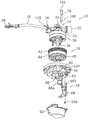
- FIG. 2 is a perspective view showing the tone arm unit according to the first embodiment.
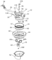
- FIG. 3 is an exploded perspective view showing the tone arm unit according to the first embodiment.
- 4 is an exploded perspective view showing the tone arm unit according to the first embodiment in a state viewed from an angle different from that in FIG.
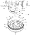
- FIG. 5 is an exploded perspective view showing the lifting mechanism according to the first embodiment.
- FIG. 6 is an exploded perspective view showing the lifting mechanism according to the first embodiment when viewed from an angle different from that in FIG. 5.
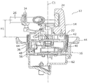
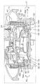
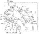
- 7A is a cross-sectional view taken along line VII-VII in FIG. 2 in a state where the arm member is lowered most.
- FIG. 7B is an enlarged cross-sectional perspective view showing a part of FIG. 7A.
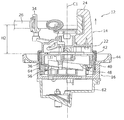
- FIG. 8A is a cross-sectional view taken along line VII-VII in FIG. 2 in a state where the arm member is raised most.
- FIG. 8B is a cross-sectional perspective view showing a part of FIG. 8A in an enlarged manner.
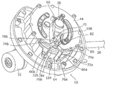
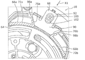
- FIG. 9 is a perspective view showing the lock mechanism according to the first embodiment.
- FIG. 10 is a perspective view showing the lock mechanism according to the first embodiment in a state where the lock plate is omitted.
- FIG. 11 is a perspective view showing a part of the lock mechanism according to the first embodiment.
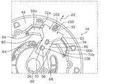
- FIG. 12A is a plan view showing the tone arm unit according to Embodiment 1 in a state where each of the pair of lock supports is located at a release position.
- FIG. 12B is an enlarged view of a part of the lock mechanism according to Embodiment 1 in a state where each of the pair of lock supports is located at the release position.
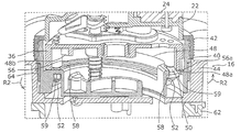
- 12C is a cross-sectional view taken along the line XII-XII of FIG. 9 in a state where each of the pair of lock supports is located at the release position.
- FIG. 13A is a plan view showing the tone arm unit according to Embodiment 1 in a state where each of the pair of lock supports is located at the lock position.
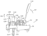
- FIG. 14A is a perspective view showing the lifter mechanism according to Embodiment 1 in a state where the mounting table is located at the upper limit position.
- FIG. 14B is a side view showing the lifter mechanism according to Embodiment 1 in a state where the mounting table is located at the upper limit position.
- FIG. 14C is a side view showing the tone arm unit according to Embodiment 1 in a state where the mounting table is located at the upper limit position.
- FIG. 15A is a perspective view showing the lifter mechanism according to Embodiment 1 in a state where the mounting table is located at the lower limit position.
- FIG. 15B is a side view showing the lifter mechanism according to Embodiment 1 in a state where the mounting table is located at the lower limit position.
- FIG. 15C is a side view showing the tone arm unit according to Embodiment 1 in a state where the mounting table is located at the lower limit position.
- FIG. 16 is a perspective view showing a lock mechanism according to the second embodiment.
- FIG. 17 is a perspective view showing the lock mechanism according to the second embodiment in a state where a pair of lock supports, a lock plate, and the like are omitted.
- FIG. 18 is a perspective view showing a part of the lock mechanism according to the second embodiment.
- FIG. 19 is a perspective view showing the lock mechanism according to Embodiment 2 in a state where each of the pair of lock supports is located at the release position.
- FIG. 20 is a perspective view showing the lock mechanism according to Embodiment 2 in a state where each of the pair of lock supports is located at the lock position.
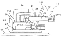
- FIG. 1 is a perspective view showing a playback apparatus 2 according to the first embodiment.
- the playback device 2 is a device for playing back a record board 4 (so-called record player).
- the playback device 2 includes a housing 6, a turntable 8, a drive source 10, and a tone arm unit 12.
- the housing 6 has a substantially rectangular box shape in plan view.
- the turntable 8 is a disk-like table on which the record board 4 is placed, and is rotatably supported on the upper surface of the housing 6.
- the drive source 10 is a motor for rotating the turntable 8 and is disposed inside the housing 6.
- the tone arm unit 12 is a unit for picking up an audio signal from the record board 4 mounted on the turntable 8 that rotates, and is disposed adjacent to the turntable 8 on the upper surface of the housing 6.
- the reproduction apparatus 2 of the present embodiment is characterized by the configuration of the tone arm unit 12.
- the configuration of the tone arm unit 12 will be described in detail.
- FIG. 2 is a perspective view showing the tone arm unit 12 according to the first embodiment.
- FIG. 3 is an exploded perspective view showing the tone arm unit 12 according to the first embodiment.
- 4 is an exploded perspective view showing the tone arm unit 12 according to the first embodiment when viewed from an angle different from that in FIG.
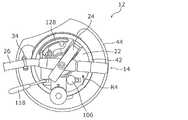
- the tone arm unit 12 includes a tone arm unit 14, an elevating mechanism 16, a lock mechanism 18, and a lifter mechanism 20.
- a tone arm unit 14 an elevating mechanism 16
- a lock mechanism 18 a lock mechanism 18
- a lifter mechanism 20 a lifter mechanism 20
- tone arm unit 14 will be described with reference to FIGS.
- the tone arm unit 14 includes an arm base 22, a support mechanism 24, and an arm member 26.
- the arm base 22 is a member for supporting the arm member 26 and the like, and is formed in a circular shape in plan view.
- the support mechanism 24 is a mechanism for supporting the base end portion of the arm member 26 so as to be swingable in the horizontal direction and the vertical direction, and is disposed on the upper surface of the arm base 22.
- the arm member 26 extends in a long shape while being bent in a substantially S shape within a horizontal plane.
- a head shell 28 is supported at the tip of the arm member 26.
- a cartridge 30 (see FIG. 1) having a record needle is detachably attached to the head shell 28.
- a balance weight 32 for supporting a weight balance with the head shell 28 is supported at the base end portion of the arm member 26.
- the user When the record board 4 is not reproduced, the user supports the arm member 26 on a hook-shaped armrest 34 disposed on the upper surface of the arm base 22.
- the user When playing back the record board 4, after the user removes the arm member 26 from the arm rest 34, the user places the arm member 26 on a mounting table 128 (described later) while swinging the arm member 26 in the horizontal direction and the vertical direction. .
- the mounting table 128 As will be described later, when the mounting table 128 is lowered while the arm member 26 is mounted, the head shell 28 approaches the record board 4 on the turntable 8, and the record needle of the cartridge 30 moves through the groove of the record board 4. Trace.
- FIG. 5 is an exploded perspective view showing the lifting mechanism 16 according to the first embodiment.
- 6 is an exploded perspective view showing the lifting mechanism 16 according to the first embodiment when viewed from an angle different from that in FIG. 7A is a cross-sectional view taken along line VII-VII in FIG. 2 in a state where the arm member 26 is lowered most.
- FIG. 7B is an enlarged cross-sectional perspective view showing a part of FIG. 7A.
- the elevating mechanism 16 is a mechanism for elevating and lowering the arm member 26 with respect to the record board 4 on the turntable 8. As shown in FIGS. 3 and 4, the elevating mechanism 16 includes a cam base 36 (an example of a support member), a center shaft 38, a ring cam 40 (an example of a rotating member), an operation ring 42, and an arm base mount 44. And have.
- the cam base 36 is formed in a disc shape, and is fixed to the lower surface of the arm base 22 with a plurality of screws 46. That is, the cam base 36 supports the arm member 26 via the arm base 22.
- a plurality (three in the present embodiment) of first guide portions 48 are formed on the outer peripheral portion of the lower surface of the cam base 36.
- the plurality of first guide portions 48 are arranged side by side along the rotation direction of the ring cam 40 (that is, the circumferential direction of the cam base 36).
- Each of the plurality of first guide portions 48 extends while inclining along the rotation direction of the ring cam 40. That is, each of the plurality of first guide portions 48 extends in an arc shape while being inclined upward from the peak portion 48a to the valley portion 48b.
- a plurality (three in this embodiment) of protrusions 50 are formed on the outer peripheral portion of the lower surface of the cam base 36.
- the plurality of protrusions 50 extend vertically downward from the lower surface of the cam base 36 and are arranged at intervals along the rotational direction of the ring cam 40.
- a screw hole 50 a for screwing a retaining screw 52 is formed at the tip of each of the plurality of protrusions 50.
- the center shaft 38 is formed in a columnar shape, and extends vertically downward from the center portion on the lower surface of the cam base 36.
- a center axis C1 (an example of a predetermined axis) of the center shaft 38 extends in the vertical direction, and functions as a lift axis when the cam base 36 moves up and down with respect to the ring cam 40 as described later. Further, the center axis C1 of the center shaft 38 also functions as a rotation axis when the ring cam 40 rotates with respect to the cam base 36, as will be described later.
- the center shaft 38 is formed of a metal such as free-cutting steel or brass, for example.
- the ring cam 40 is formed in a bottomed cylindrical shape, and is disposed at a position covering the outer surface and the lower surface of the cam base 36.
- a circular hole 54 through which the center shaft 38 is inserted is formed at the center of the bottom of the ring cam 40.
- the ring cam 40 is rotatable with respect to the cam base 36 around the central axis C1 of the center shaft 38.
- a plurality (three in this embodiment) of second guide portions 56 are formed on the outer peripheral portion of the top surface of the bottom portion of the ring cam 40.
- the plurality of second guide portions 56 are arranged side by side along the rotation direction of the ring cam 40 (that is, the circumferential direction of the ring cam 40) corresponding to the plurality of first guide portions 48, respectively.
- Each of the plurality of second guide portions 56 extends so as to face the corresponding first guide portion 48 and incline along the rotation direction of the ring cam 40. That is, each of the plurality of second guide portions 56 extends in an arc shape while being inclined upward from the valley portion 56b to the peak portion 56a.
- the plurality of second guide portions 56 are close to the plurality of first guide portions 48, and the first guide portion 48 and the second guide portion 56 are connected to each other. For example, a gap of about 0.1 mm is formed between them.
- a plurality (three in the present embodiment) of groove portions 58 are formed on the outer peripheral portion of the bottom portion of the ring cam 40.
- the plurality of groove portions 58 are respectively arranged at intervals along the rotation direction of the ring cam 40 corresponding to the plurality of second guide portions 56.
- Each of the plurality of groove portions 58 extends in an arc shape along the corresponding second guide portion 56.
- a plurality of protrusions 50 of the cam base 36 are movably inserted into the plurality of grooves 58, respectively. As shown in FIGS.
- a retaining screw 52 is screwed into each screw hole 50a of each of the plurality of protrusions 50 via a cam spacer 59 (an example of a retaining member). That is, the cam spacer 59 is attached to the tip of the protrusion 50 by the retaining screw 52.
- the retaining screw 52 and the cam spacer 59 are disposed on the opposite side of the cam base 36 with the groove 58 interposed therebetween.
- the cam spacer 59 is wider than the groove 58.
- the operation ring 42 is attached to the outer surface of the upper end portion of the ring cam 40.
- the user can rotate the ring cam 40 relative to the cam base 36 by grasping the operation ring 42 with fingers.
- the arm base mount 44 is formed in a bottomed cylindrical shape, and is disposed at a position covering the outer surface of the ring cam 40 and the lower surface of the bottom portion.
- a circular hole 60 through which the center shaft 38 is inserted is formed at the center of the bottom of the arm base mount 44.
- a ring cam 40 is rotatably supported on the upper surface of the bottom of the arm base mount 44.
- the arm base mount 44 is made of metal such as aluminum die cast.
- a jack base 62 is attached to the lower end of the arm base mount 44. Inside the jack base 62, a jack substrate (not shown) on which jack terminals are mounted is disposed.
- FIGS. 7A to 8B are cross-sectional views taken along the line VII-VII in FIG. 2 in a state where the arm member 26 is raised most.
- FIG. 8B is a cross-sectional perspective view showing a part of FIG. 8A in an enlarged manner.
- each peak portion 56a of the plurality of second guide portions 56 faces the valley portion 48b of the corresponding first guide portion 48.
- the arm member 26 is lowered most with respect to the record board 4 on the turntable 8, and the height H1 of the arm member 26 from the upper end surface of the arm base mount 44 is the lowest.
- the user rotates the ring cam 40 with respect to the cam base 36 in a direction indicated by an arrow R1 in FIG. 7B by a predetermined angle (for example, + 120 °), so that a plurality of second guide portions 56 are provided. It slides along the first guide part 48. At this time, each peak portion 56a of the plurality of second guide portions 56 moves from the valley portion 48b of the corresponding first guide portion 48 toward the peak portion 48a. Accordingly, the cam base 36 is raised along the central axis C ⁇ b> 1 of the center shaft 38 with respect to the ring cam 40 by being pushed up by the crest portions 56 a of the plurality of second guide portions 56.
- a predetermined angle for example, + 120 °
- the arm member 26 rises along the central axis C ⁇ b> 1 of the center shaft 38 with respect to the record board 4 on the turntable 8 together with the cam base 36 and the arm base 22. While the ring cam 40 is rotated with respect to the cam base 36, the protrusion 50 of the cam base 36 moves along the groove 58 from one end of the groove 58 to the other end.
- each peak portion 56a of the plurality of second guide portions 56 is opposed to the corresponding peak portion 48a of the first guide portion 48.
- the arm member 26 is most elevated with respect to the record board 4 on the turntable 8, and the height H2 (> H1) of the arm member 26 from the upper end surface of the arm base mount 44 is the highest. ing.
- the difference (H2 ⁇ H1) between the height H2 and the height H1 is, for example, about 6 mm.
- the ring cam 40 is rotated by a predetermined angle (for example, ⁇ 120 °) in the direction indicated by the arrow R2 in FIG. Slide along the first guide portion 48.
- a predetermined angle for example, ⁇ 120 °
- each peak portion 56a of the plurality of second guide portions 56 moves from the peak portion 48a of the corresponding first guide portion 48 toward the valley portion 48b.
- the cam base 36 descends along the center axis C ⁇ b> 1 of the center shaft 38 with respect to the ring cam 40.
- the arm member 26 moves down along with the cam base 36 and the arm base 22 along the center axis C ⁇ b> 1 of the center shaft 38 with respect to the record board 4 on the turntable 8. While the ring cam 40 is rotated with respect to the cam base 36, the protrusion 50 of the cam base 36 moves along the groove 58 from the other end of the groove 58 to one end.
- the height position of the arm member 26 from the record board 4 can be adjusted by moving the arm member 26 up and down with respect to the record board 4 on the turntable 8. Thereby, when the record needle traces the groove of the record board 4, the posture of the arm member 26 can be kept substantially horizontal, and the audio signal can be picked up from the record board 4 with high accuracy.
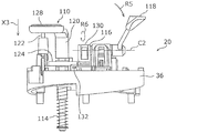
- FIG. 9 is a perspective view showing the lock mechanism 18 according to the first embodiment.
- FIG. 10 is a perspective view showing the lock mechanism 18 according to the first embodiment in a state where the lock plate 68 is omitted.
- FIG. 11 is a perspective view showing a part of the lock mechanism 18 according to the first embodiment.
- the jack base 62 and the like are not shown in FIGS. 9 and 10.
- the lock mechanism 18 is a mechanism for locking (regulating) the rotation of the ring cam 40 relative to the cam base 36. As shown in FIGS. 3, 4, and 9, the lock mechanism 18 includes a ring rubber 64 (an example of an elastic member), a pair of lock supports 66a and 66b (an example of a contact member), a lock plate 68, a lock And a shaft 70 (an example of an operation member).
- the ring rubber 64 is attached to the outer surface of the ring cam 40 and extends in a ring shape over the entire circumference of the outer surface of the ring cam 40.
- the ring rubber 64 is made of, for example, a rubber material.
- the ring rubber 64 is formed of a rubber material, but is not limited thereto, and may be formed of various elastic materials such as a resin material.
- the pair of lock supports 66 a and 66 b are members that are movably attached to the arm base mount 44 and lock the rotation of the ring cam 40 relative to the cam base 36 by contacting the ring rubber 64.
- the pair of lock supports 66a and 66b are made of, for example, resin.
- the lock support 66a has a support main body 72a and a mounting piece 74a.
- the support main body 72 a is formed in a plate shape and is curved along the circumferential direction of the outer surface of the ring cam 40.
- An inclined surface 76a is formed on one side of the support main body 72a.
- the attachment piece 74a extends from the concave surface side of the support main body 72a.
- a long hole 78a is formed in the mounting piece 74a.
- the lock support 68b is formed symmetrically with the lock support 68a described above. That is, the lock support 68b has a support main body 72b and an attachment piece 74b.
- the support main body 72 b is formed in a plate shape and is curved along the circumferential direction of the outer surface of the ring cam 40.
- An inclined surface 76b is formed on one side of the support main body 72b.
- the attachment piece 74b extends from the concave surface side of the support main body 72b.
- a long hole 78b is formed in the mounting piece 74b.
- the pair of lock supports 66a and 66b are disposed in a notch 80 formed on the side wall of the arm base mount 44, and each mounting piece 74a, 74b is adjacent to each other so as to face each other.
- a part of the ring rubber 64 is exposed to the outside of the arm base mount 44 through the notch 80 of the arm base mount 44. Therefore, the concave surface side of each of the support main body portions 72 a and 72 b of the pair of lock supports 66 a and 66 b faces a part of the ring rubber 64.
- each of the pair of lock supports 66a and 66b has a release position (see FIGS. 12B and 12C described later) where the support main body portions 72a and 72b are separated from the ring rubber 64, and the support main body portions 72a and 72b are ring rubber 64. It is possible to move between lock positions (see FIGS. 13B and 13C, which will be described later) in contact with.
- a cushion member having elasticity between the support main body portions 72a and 72b of each of the pair of lock supports 66a and 66b and the peripheral portion of the cutout portion 80 of the arm base mount 44. 84 is interposed.
- the lock plate 68 is a member for pushing each of the pair of lock supports 66a and 66b from the release position toward the lock position.
- the lock plate 68 is made of a metal such as iron, for example. As shown in FIGS. 3, 4, 9, and 11, the lock plate 68 includes a horizontal portion 86, a vertical portion 88, a pushing portion 90, and an attachment portion 92.
- the horizontal portion 86 is formed with a long hole 94 through which the protrusion 82 of the arm base mount 44 is movably inserted, and a hole 96 through which an eccentric shaft 108 (described later) of the lock shaft 70 is rotatably inserted.
- the vertical portion 88 extends substantially perpendicularly to the horizontal portion 86 from one end portion of the horizontal portion 86.
- the pushing portion 90 is formed at one end portion of the vertical portion 88 and extends substantially perpendicular to the vertical portion 88.
- a pair of inclined portions 98a and 98b are formed at both ends of the pushing portion 90, respectively.
- the attachment portion 92 extends substantially parallel to the horizontal portion 86 from the central portion of the push-in portion 90.
- a long hole 102 for inserting the screw 100 is formed in the mounting portion 92.
- the pair of inclined portions 98a and 98b of the push-in portion 90 are inclined surfaces 76a and 76b of the support main body portions 72a and 72b of the pair of lock supports 66a and 66b, respectively. Touching.
- the lock shaft 70 is a member for moving each of the pair of lock supports 66a and 66b between the release position and the lock position. As shown in FIGS. 3 and 4, the lock shaft 70 is formed in an elongated shape, and is disposed through the arm base 22, the cam base 36, the ring cam 40, and the arm base mount 44. The lock shaft 70 is rotatable with respect to the arm base mount 44 about the central axis thereof.
- a lock knob 106 is formed at the upper end of the lock shaft 70. As shown in FIG. 12A described later, the lock knob 106 is disposed on the upper surface of the arm base 22. The user can rotate the lock shaft 70 relative to the arm base mount 44 by grasping the lock knob 106 with fingers.
- An eccentric shaft 108 that is eccentric with respect to the central axis of the lock shaft 70 is formed at the lower end of the lock shaft 70. As shown in FIG. 9, the eccentric shaft 108 is rotatably inserted into the hole 96 in the horizontal portion 86 of the lock plate 68.
- FIG. 12A is a plan view showing the tone arm unit 12 according to Embodiment 1 in a state where each of the pair of lock supports 66a and 66b is located at the release position.
- FIG. 12B is an enlarged view of a part of the lock mechanism 18 according to Embodiment 1 in a state where each of the pair of lock supports 66a and 66b is located at the release position.
- 12C is a cross-sectional view taken along the line XII-XII of FIG. 9 in a state where each of the pair of lock supports 66a and 66b is located at the release position.
- FIG. 12A is a plan view showing the tone arm unit 12 according to Embodiment 1 in a state where each of the pair of lock supports 66a and 66b is located at the release position.
- FIG. 12B is an enlarged view of a part of the lock mechanism 18 according to Embodiment 1 in a state where each of the pair of lock supports 66a and 66b is located at
- FIG. 13A is a plan view showing the tone arm unit 12 according to Embodiment 1 in a state where each of the pair of lock supports 66a and 66b is located at the lock position.
- FIG. 13B is an enlarged view showing a part of the lock mechanism 18 according to Embodiment 1 in a state where each of the pair of lock supports 66a and 66b is located at the lock position.
- 13C is a cross-sectional view taken along line XII-XII in FIG. 9 in a state where each of the pair of lock supports 66a and 66b is located at the lock position.
- the balance weight 32 is not shown in FIGS. 12A and 13A.
- each of the pair of lock supports 66a and 66b is located at the release position.
- the support main body portions 72a and 72b of the pair of lock supports 66a and 66b are separated from the ring rubber 64, the ring cam 40 can be rotated with respect to the cam base 36.
- the pair of inclined portions 98a and 98b of the push-in portion 90 push the inclined surfaces 76a and 76b of the support main body portions 72a and 72b of the pair of lock supports 66a and 66b, respectively.
- Each of the pair of lock supports 66a and 66b moves from the release position to the lock position.
- the cushion member 84 is compressed by being pressed by the support main body portions 72a and 72b of the pair of lock supports 66a and 66b.
- each of the support main body portions 72a and 72b of the pair of lock supports 66a and 66b is connected to the ring rubber 64. Touching. Accordingly, the rotation of the ring cam 40 relative to the cam base 36 is locked by the frictional force generated between the support main body portions 72a and 72b and the ring rubber 64. At this time, the ring rubber 64 is elastically deformed by being pressed (contacted) by the support main body portions 72a and 72b.
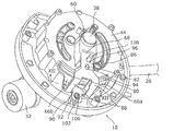
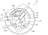
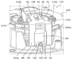
- FIG. 14A is a perspective view showing lifter mechanism 20 according to Embodiment 1 in a state where mounting table 128 is located at the upper limit position.
- FIG. 14B is a side view showing the lifter mechanism 20 according to Embodiment 1 in a state where the mounting table 128 is located at the upper limit position.
- FIG. 14C is a side view showing the tone arm unit 12 according to Embodiment 1 in a state where the mounting table 128 is located at the upper limit position.
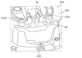
- FIG. 15A is a perspective view showing the lifter mechanism 20 according to Embodiment 1 in a state where the mounting table 128 is located at the lower limit position.
- FIG. 15B is a side view showing the lifter mechanism 20 according to Embodiment 1 in a state where the mounting table 128 is located at the lower limit position.
- FIG. 15C is a side view showing the tone arm unit 12 according to Embodiment 1 in a state where the mounting table 128 is located at the lower limit position.
- the arm base 22 and the arm member 26 are not shown in FIGS. 14A, 14B, 15A, and 15B.
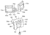
- the lifter mechanism 20 is a mechanism for lowering the head shell 28 (the tip of the arm member 26) toward the record board 4 on the turntable 8. As shown in FIG. 14A, the lifter mechanism 20 includes a lift arm base 110, a gear damper 112, a coil spring 114 (an example of a second urging member), a cam member 116, and a lever member 118. Yes.
- the lift arm base 110 has a pair of support columns 120, 122, a plate member 124, a rack gear 126, and a mounting table 128.
- the pair of support columns 120 and 122 are supported by the cam base 36 so as to be movable up and down, and extend vertically upward from the upper surface of the cam base 36.
- the plate member 124 is attached to the support 120 and can be moved up and down together with the support 120.
- the rack gear 126 extends vertically downward from the plate member 124 and can be moved up and down together with the support 120.
- the mounting table 128 is a member for mounting the arm member 26, and is supported by the upper ends of the pair of support columns 120 and 122.
- the mounting table 128 can be moved up and down between an upper limit position (see FIGS. 14A to 14C) and a lower limit position (see FIGS. 15A to 15C) by moving the pair of support columns 120 and 122 up and down.
- an upper limit position see FIGS. 14A to 14C
- a lower limit position see FIGS. 15A to 15C
- the gear damper 112 is rotatably supported on the upper surface of the cam base 36.
- the gear damper 112 is meshed with the rack gear 126 of the lift arm base 110.
- the gear damper 112 applies a braking force (that is, a force against the lowering operation of the mounting table 128) to the mounting table 128 when the mounting table 128 is lowered from the upper limit position to the lower limit position.
- the coil spring 114 is disposed so as to cover the outer surface of the support column 120 below the cam base 36, and biases the mounting table 128 (support column 120) from the upper limit position toward the lower limit position. To do.
- the cam member 116 is rotatably supported on the upper surface of the cam base 36.
- the cam member 116 has a cam main body 130 and a support portion 132.
- the cam main body 130 rotates about a rotation axis C2 extending in a substantially horizontal direction.
- the support portion 132 is formed at a position eccentric from the rotation axis C ⁇ b> 2 of the cam main body portion 130.
- the lever member 118 is connected to the cam main body 130 of the cam member 116.
- the cam member 116 is moved between the first rotation position (see FIGS. 14A and 14B) and the second rotation position (see FIGS. 15A and 15B). Can be rotated.
- FIG. 14B when the cam member 116 is located at the first rotation position, the support portion 132 supports the plate member 124 from below. Thereby, the cam member 116 holds the mounting table 128 at the upper limit position.
- FIG. 15B when the cam member 116 is located at the second rotation position, the support portion 132 does not support the plate member 124 from below. As a result, the cam member 116 releases the holding of the mounting table 128 at the upper limit position.
- the cam member 116 is positioned at the first rotation position, and the mounting table 128 is held at the upper limit position.
- the user rotates the lever member 118 in the direction indicated by the arrow R5 in FIGS. 15A to 15C while the turntable 8 is rotating.
- the cam member 116 rotates from the first rotation position to the second rotation position in the direction indicated by the arrow R6 in FIGS. 15A and 15B.
- the mounting table 128 is lowered from the upper limit position toward the lower limit position in the direction indicated by the arrow X3 in FIGS. 15A to 15C with the arm member 26 being mounted by the biasing force of the coil spring 114.
- the mounting table 128 is gently lowered from the upper limit position toward the lower limit position while receiving the braking force from the gear damper 112, so that the record needle can be brought closer to the record board 4 gently. As a result, the reproduction of the record board 4 can be started smoothly.
- the user rotates the lever member 118 in the direction indicated by the arrow R7 in FIGS. 14A to 14C from the state shown in FIGS. 15A to 15C.
- the cam member 116 rotates from the second rotation position to the first rotation position in the direction indicated by the arrow R8 in FIGS. 14A and 14B.
- the mounting table 128 is pushed up by the support portion 132 of the cam member 116, and with the arm member 26 mounted, the mounting table 128 is directed from the lower limit position to the upper limit position in the direction indicated by the arrow X4 in FIGS. 14A to 14C. Rise. Thereby, the record needle can be separated from the record board 4.
- the tone arm unit 12 is used in the playback device 2 that plays back the record board 4.
- the tone arm unit 12 includes an arm member 26 for attaching the cartridge 30 to the tip portion, and an elevating mechanism 16 for elevating the arm member 26 with respect to the record board 4 along a predetermined axis.
- the elevating mechanism 16 is formed on a cam base 36 that supports the arm member 26, a ring cam 40 that is rotatable about a predetermined axis with respect to the cam base 36, and the cam base 36.
- a first guide portion 48 extending while inclining along, and a second guide portion 56 formed on the ring cam 40 and extending while inclining along the rotation direction so as to face the first guide portion 48.
- the cam base 36 moves up and down with respect to the ring cam 40 as the second guide portion 56 slides along the first guide portion 48.
- the elevating mechanism 16 can be easily incorporated into the tone arm unit 12 by arranging the cam base 36 and the ring cam 40 so that the first guide portion 48 and the second guide portion 56 face each other. it can. It should be noted that only the structure of the elevating mechanism 16 can be changed without greatly changing the appearance of a playback apparatus equipped with a conventional tone arm unit. As a result, the degree of satisfaction is high for users who prefer the classical appearance of conventional playback devices.
- the elevating mechanism 16 is further formed in the ring cam 40, formed in the groove portion 58 extending along the second guide portion 56, and the cam base 36, and is movably inserted into the groove portion 58.
- the projection 50 has a cam spacer 59 attached to the tip of the projection 50.
- the cam spacer 59 can suppress the protrusion 50 from coming out of the groove 58.
- the cam base 36 can be prevented from being unexpectedly detached from the ring cam 40.
- each of the first guide part 48 and the second guide part 56 is arranged in a plurality along the rotation direction.
- the tone arm unit 12 further includes a lock mechanism 18 for locking the rotation of the ring cam 40 relative to the cam base 36.
- the lock mechanism 18 includes a ring rubber 64 disposed on the outer surface of the ring cam 40, lock supports 66a and 66b movable between a lock position in contact with the ring rubber 64 and a release position away from the ring rubber 64.
- a lock shaft 70 is provided for moving the lock supports 66a and 66b between the lock position and the release position.
- the ring rubber 64 is formed of a rubber material and extends in a ring shape over the entire outer surface of the ring cam 40.
- the lock supports 66a and 66b can be reliably brought into contact with the ring rubber 64 regardless of the rotation position of the ring cam 40 with respect to the cam base 36.
- the tone arm unit 12 further includes a lifter mechanism 20 for lowering the tip of the arm member 26 toward the record board 4.
- the lifter mechanism 20 is a mounting table 128 on which the arm member 26 is placed, and an upper limit position where the distal end portion of the arm member 26 is separated from the record board 4, and a lower limit position where the distal end portion of the arm member 26 is brought closer to the record board 4.
- a gear damper 112 that applies a braking force to the mounting table 128 when the mounting table 128 is lowered from the upper limit position to the lower limit position.
- the mounting table 128 is gently lowered from the upper limit position toward the lower limit position while receiving the braking force by the gear damper 112, so that the tip of the arm member 26 can be brought closer to the record board 4 gently. As a result, the reproduction of the record board 4 can be started smoothly.
- the lifter mechanism 20 further includes a coil spring 114 that urges the mounting table 128 from the upper limit position toward the lower limit position, and a first rotation position that holds the mounting table 128 at the upper limit position.
- the cam member 116 that rotates between the second rotation position for releasing the holding of the mounting table 128 at the upper limit position, and the cam member 116 between the first rotation position and the second rotation position.
- a lever member 118 that rotates between them.
- the user can easily raise and lower the mounting table 128 between the upper limit position and the lower limit position by operating the lever member 118.
- the playback device 2 that plays back the record board 4 includes a turntable 8 on which the record board 4 is placed, a drive source 10 that rotates the turntable 8, and a turntable that rotates. 8 and any one of the above-described tone arm units 12 for picking up an audio signal from the record board 4 placed on the recording board 4.
- the elevating mechanism 16 can be easily incorporated into the tone arm unit 12 by arranging the cam base 36 and the ring cam 40 so that the first guide portion 48 and the second guide portion 56 face each other. it can. It should be noted that only the structure of the elevating mechanism 16 can be changed without greatly changing the appearance of a playback apparatus equipped with a conventional tone arm unit. As a result, the degree of satisfaction is high for users who prefer the classical appearance of conventional playback devices.
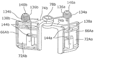
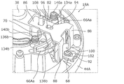
- FIG. 16 is a perspective view showing a lock mechanism 18A according to the second embodiment.
- FIG. 17 is a perspective view showing the lock mechanism 18A according to the second embodiment in a state where the pair of lock supports 66Aa, 66Ab, the lock plate 68, and the like are omitted.
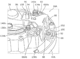
- FIG. 18 is a perspective view showing a part of the lock mechanism 18A according to the second embodiment.
- the jack base 62 and the like are not shown in FIGS. 16 and 17.
- the lock mechanism 18A includes a pair of spring members 134a and 134b (an example of a first biasing member) in addition to the components of the lock mechanism 18 according to the first embodiment. Yes.
- the spring member 134a is formed of a coiled torsion spring portion 136a and a wire spring portion 138a extending from the torsion spring portion 136a.
- the screw 140a is screwed into the screw hole 142a formed in the arm base mount 44A through the torsion spring portion 136a, whereby the torsion spring portion 136a is attached to the arm base mount 44A.
- the wire spring portion 138a is inserted through an opening 144a formed in the support main body portion 72Aa of the lock support 66Aa.
- the spring member 134b is formed symmetrically with the spring member 134a described above. That is, as shown in FIGS. 16 and 18, the spring member 134b is formed of a coiled torsion spring part 136b and a wire spring part 138b extending from the torsion spring part 136b. As shown in FIGS. 16 and 17, the screw 140b is screwed into the screw hole 142b formed in the arm base mount 44A through the torsion spring portion 136b, so that the torsion spring portion 136b is attached to the arm base mount 44A. . As shown in FIGS. 16 and 18, the wire spring portion 138b is inserted through an opening 144b formed in the support main body portion 72Ab of the lock support 66Ab.
- FIG. 19 is a perspective view showing the lock mechanism 18A according to Embodiment 2 in a state where each of the pair of lock supports 66Aa and 66Ab is located at the release position.
- FIG. 20 is a perspective view showing the lock mechanism 18A according to Embodiment 2 in a state where each of the pair of lock supports 66Aa and 66Ab is located at the lock position.
- the jack base 62 and the like are not shown in FIGS. 19 and 20.
- each of the pair of lock supports 66Aa and 66Ab is located at the release position. From this state, when the user rotates the lock shaft 70 in a predetermined direction with respect to the arm base mount 44A, as shown in FIG. 20, each of the pair of lock supports 66Aa and 66Ab is locked from the release position. Move to position. At this time, the wire spring portion 138a of the spring member 134a and the wire spring portion 138b of the spring member 134b are elastically deformed by being pressed by the pair of lock supports 66Aa and 66Ab, respectively. The torsion spring part 136a of the spring member 134a and the torsion spring part 136b of the spring member 134b are hardly elastically deformed.
- the lock mechanism 18A further includes spring members 134a and 134b that urge the lock supports 66Aa and 66Ab from the lock position toward the release position.
- the ring rubber 64 has adhesiveness. Even in such a case, the lock supports 66Aa and 66Ab can be easily separated from the ring rubber 64 by the biasing force of the spring members 134a and 134b.
- Embodiments 1 and 2 have been described as examples of the technology disclosed in the present application. However, the technology in the present disclosure is not limited to this, and can also be applied to an embodiment in which changes, replacements, additions, omissions, and the like are appropriately performed. Moreover, it is also possible to combine each component demonstrated in the said Embodiment 1 and 2 into a new embodiment.
- a gap is formed between the first guide portion 48 and the second guide portion 56, but the present invention is not limited to this, and the first guide portion 48 and the second guide portion 56 May be brought into contact with each other.
- This disclosure is applicable to a tone arm unit used in a playback device for playing a record board.
Landscapes
- Holding Or Fastening Of Disk On Rotational Shaft (AREA)
- Transmission Devices (AREA)
Priority Applications (2)
| Application Number | Priority Date | Filing Date | Title |
|---|---|---|---|
| EP17889108.1A EP3564956B1 (en) | 2016-12-28 | 2017-10-23 | Tonearm unit and playback device |
| US16/348,088 US10789974B2 (en) | 2016-12-28 | 2017-10-23 | Tonearm unit and playback device |
Applications Claiming Priority (2)
| Application Number | Priority Date | Filing Date | Title |
|---|---|---|---|
| JP2016256002A JP6516164B2 (ja) | 2016-12-28 | 2016-12-28 | トーンアームユニット及び再生装置 |
| JP2016-256002 | 2016-12-28 |
Publications (1)
| Publication Number | Publication Date |
|---|---|
| WO2018123232A1 true WO2018123232A1 (ja) | 2018-07-05 |
Family
ID=62708173
Family Applications (1)
| Application Number | Title | Priority Date | Filing Date |
|---|---|---|---|
| PCT/JP2017/038117 Ceased WO2018123232A1 (ja) | 2016-12-28 | 2017-10-23 | トーンアームユニット及び再生装置 |
Country Status (4)
| Country | Link |
|---|---|
| US (1) | US10789974B2 (enExample) |
| EP (1) | EP3564956B1 (enExample) |
| JP (1) | JP6516164B2 (enExample) |
| WO (1) | WO2018123232A1 (enExample) |
Cited By (1)
| Publication number | Priority date | Publication date | Assignee | Title |
|---|---|---|---|---|
| WO2020137030A1 (ja) * | 2018-12-27 | 2020-07-02 | パナソニックIpマネジメント株式会社 | トーンアーム装置及び再生装置 |
Families Citing this family (1)
| Publication number | Priority date | Publication date | Assignee | Title |
|---|---|---|---|---|
| JP1625836S (enExample) * | 2018-08-21 | 2019-03-04 |
Citations (4)
| Publication number | Priority date | Publication date | Assignee | Title |
|---|---|---|---|---|
| JPS5110904A (ja) * | 1974-07-16 | 1976-01-28 | Sony Corp | Pitsukuatsupuaamusochi |
| JPS5182402U (enExample) * | 1974-12-24 | 1976-07-01 | ||
| JPS61296502A (ja) * | 1985-06-22 | 1986-12-27 | Audio Technica Corp | レコ−ドプレ−ヤ用ピツクアツプ |
| US6154435A (en) * | 1998-12-01 | 2000-11-28 | Ya Horng Electronic Co., Ltd. | Height adjusting device for a tone arm |
Family Cites Families (7)
| Publication number | Priority date | Publication date | Assignee | Title |
|---|---|---|---|---|
| US3307851A (en) * | 1963-08-20 | 1967-03-07 | Rca Corp | Automatic record changer |
| US3411791A (en) * | 1966-03-31 | 1968-11-19 | James T. Dennis | Automatic record changer |
| DE2164875A1 (enExample) * | 1970-12-29 | 1972-08-31 | Pioneer Electronic Corp | |
| US3973777A (en) * | 1974-12-30 | 1976-08-10 | Avnet, Inc. | Cueing control |
| US5003522A (en) * | 1978-12-01 | 1991-03-26 | Dolby Ray Milton | Disc reproducing system for compensating mechanical imperfections |
| NL8402144A (nl) * | 1984-07-06 | 1986-02-03 | Philips Nv | Platenspeler met een liftinrichting voor de toonarm. |
| JPH06187601A (ja) | 1992-12-18 | 1994-07-08 | Teragaki Kenkyusho:Kk | トーンアーム |
-
2016
- 2016-12-28 JP JP2016256002A patent/JP6516164B2/ja active Active
-
2017
- 2017-10-23 US US16/348,088 patent/US10789974B2/en active Active
- 2017-10-23 WO PCT/JP2017/038117 patent/WO2018123232A1/ja not_active Ceased
- 2017-10-23 EP EP17889108.1A patent/EP3564956B1/en active Active
Patent Citations (4)
| Publication number | Priority date | Publication date | Assignee | Title |
|---|---|---|---|---|
| JPS5110904A (ja) * | 1974-07-16 | 1976-01-28 | Sony Corp | Pitsukuatsupuaamusochi |
| JPS5182402U (enExample) * | 1974-12-24 | 1976-07-01 | ||
| JPS61296502A (ja) * | 1985-06-22 | 1986-12-27 | Audio Technica Corp | レコ−ドプレ−ヤ用ピツクアツプ |
| US6154435A (en) * | 1998-12-01 | 2000-11-28 | Ya Horng Electronic Co., Ltd. | Height adjusting device for a tone arm |
Non-Patent Citations (1)
| Title |
|---|
| See also references of EP3564956A4 * |
Cited By (4)
| Publication number | Priority date | Publication date | Assignee | Title |
|---|---|---|---|---|
| WO2020137030A1 (ja) * | 2018-12-27 | 2020-07-02 | パナソニックIpマネジメント株式会社 | トーンアーム装置及び再生装置 |
| JPWO2020137030A1 (ja) * | 2018-12-27 | 2021-09-09 | パナソニックIpマネジメント株式会社 | トーンアーム装置及び再生装置 |
| JP7054806B2 (ja) | 2018-12-27 | 2022-04-15 | パナソニックIpマネジメント株式会社 | トーンアーム装置及び再生装置 |
| US11335363B2 (en) * | 2018-12-27 | 2022-05-17 | Panasonic Intellectual Property Management Co., Ltd. | Tonearm device and reproduction device |
Also Published As
| Publication number | Publication date |
|---|---|
| EP3564956A4 (en) | 2019-12-25 |
| JP2018106793A (ja) | 2018-07-05 |
| EP3564956B1 (en) | 2021-12-08 |
| EP3564956A1 (en) | 2019-11-06 |
| JP6516164B2 (ja) | 2019-05-22 |
| US20200058321A1 (en) | 2020-02-20 |
| US10789974B2 (en) | 2020-09-29 |
Similar Documents
| Publication | Publication Date | Title |
|---|---|---|
| JP7054806B2 (ja) | トーンアーム装置及び再生装置 | |
| WO2018123232A1 (ja) | トーンアームユニット及び再生装置 | |
| KR860000656B1 (ko) | 기록원반 재생장치 | |
| US3821812A (en) | Device for moving magnetic head away from magnetic sheet in magnetic recording and reproducing apparatus of the spiral track type | |
| JPH0328753B2 (enExample) | ||
| KR850001457B1 (ko) | 기록 원반 재생장치 | |
| JPH039172Y2 (enExample) | ||
| JP2018106793A5 (enExample) | ||
| JPS6235168Y2 (enExample) | ||
| JPS5853746Y2 (ja) | シ−ト式録音再生装置のヘッド送り機構 | |
| KR100892378B1 (ko) | 디스크 플레이어의 트리거 장치 | |
| JP3090576B2 (ja) | ディスクチェンジャー装置 | |
| KR100272088B1 (ko) | 씨디플레이어의 클램퍼 지지구조 | |
| JPS6034145Y2 (ja) | 磁気シ−ト式録音再生装置の磁気ヘツド支持機構 | |
| JP3031949B2 (ja) | 円盤状記録媒体のチャッキング機構 | |
| JPS6037716Y2 (ja) | 記録再生装置 | |
| JPH0418107Y2 (enExample) | ||
| JP2583108Y2 (ja) | マルチ式ディスクプレーヤ | |
| KR100425304B1 (ko) | 광디스크 체인저 | |
| JPH0348764Y2 (enExample) | ||
| JP2007200376A (ja) | ディスクローディング装置 | |
| JPS5814370A (ja) | デイスク保持装置 | |
| JPS5958676A (ja) | 磁気デイスク装置 | |
| JP2001256705A (ja) | ディスクプレーヤ | |
| JPH0221071B2 (enExample) |
Legal Events
| Date | Code | Title | Description |
|---|---|---|---|
| 121 | Ep: the epo has been informed by wipo that ep was designated in this application |
Ref document number: 17889108 Country of ref document: EP Kind code of ref document: A1 |
|
| NENP | Non-entry into the national phase |
Ref country code: DE |
|
| ENP | Entry into the national phase |
Ref document number: 2017889108 Country of ref document: EP Effective date: 20190729 |