WO2018117313A1 - 무선 통신 시스템에서 단말의 무선 링크 및 무선 연결을 제어하기 위한 방법 및 이를 지원하는 장치 - Google Patents
무선 통신 시스템에서 단말의 무선 링크 및 무선 연결을 제어하기 위한 방법 및 이를 지원하는 장치 Download PDFInfo
- Publication number
- WO2018117313A1 WO2018117313A1 PCT/KR2016/015243 KR2016015243W WO2018117313A1 WO 2018117313 A1 WO2018117313 A1 WO 2018117313A1 KR 2016015243 W KR2016015243 W KR 2016015243W WO 2018117313 A1 WO2018117313 A1 WO 2018117313A1
- Authority
- WO
- WIPO (PCT)
- Prior art keywords
- information
- terminal
- base station
- radio
- wireless
- Prior art date
Links
- 238000000034 method Methods 0.000 title claims abstract description 206
- 238000004891 communication Methods 0.000 title claims abstract description 44
- 238000005259 measurement Methods 0.000 claims abstract description 154
- 230000004044 response Effects 0.000 claims abstract description 29
- 230000005540 biological transmission Effects 0.000 claims description 81
- 238000005516 engineering process Methods 0.000 claims description 12
- 230000008569 process Effects 0.000 description 43
- 238000007726 management method Methods 0.000 description 30
- 238000010586 diagram Methods 0.000 description 29
- 230000006870 function Effects 0.000 description 25
- 230000011664 signaling Effects 0.000 description 22
- 238000010295 mobile communication Methods 0.000 description 11
- 230000015654 memory Effects 0.000 description 8
- 238000013468 resource allocation Methods 0.000 description 8
- 238000010187 selection method Methods 0.000 description 8
- 238000012545 processing Methods 0.000 description 6
- 230000007704 transition Effects 0.000 description 6
- 230000008859 change Effects 0.000 description 5
- 238000012546 transfer Methods 0.000 description 5
- 230000036963 noncompetitive effect Effects 0.000 description 4
- 230000008054 signal transmission Effects 0.000 description 4
- 230000000694 effects Effects 0.000 description 3
- 230000007774 longterm Effects 0.000 description 3
- 238000012986 modification Methods 0.000 description 3
- 230000004048 modification Effects 0.000 description 3
- 238000012544 monitoring process Methods 0.000 description 3
- 238000012384 transportation and delivery Methods 0.000 description 3
- 101000741965 Homo sapiens Inactive tyrosine-protein kinase PRAG1 Proteins 0.000 description 2
- 102100038659 Inactive tyrosine-protein kinase PRAG1 Human genes 0.000 description 2
- 108091005487 SCARB1 Proteins 0.000 description 2
- 102100037118 Scavenger receptor class B member 1 Human genes 0.000 description 2
- 230000015556 catabolic process Effects 0.000 description 2
- 230000006835 compression Effects 0.000 description 2
- 238000007906 compression Methods 0.000 description 2
- 238000006731 degradation reaction Methods 0.000 description 2
- 238000013461 design Methods 0.000 description 2
- 239000002360 explosive Substances 0.000 description 2
- 238000001914 filtration Methods 0.000 description 2
- 230000005641 tunneling Effects 0.000 description 2
- 101100150273 Caenorhabditis elegans srb-1 gene Proteins 0.000 description 1
- ATJFFYVFTNAWJD-UHFFFAOYSA-N Tin Chemical compound [Sn] ATJFFYVFTNAWJD-UHFFFAOYSA-N 0.000 description 1
- 230000003213 activating effect Effects 0.000 description 1
- 230000003139 buffering effect Effects 0.000 description 1
- 239000000969 carrier Substances 0.000 description 1
- 230000001413 cellular effect Effects 0.000 description 1
- 238000012937 correction Methods 0.000 description 1
- 238000013500 data storage Methods 0.000 description 1
- 230000006866 deterioration Effects 0.000 description 1
- 230000009977 dual effect Effects 0.000 description 1
- 238000011156 evaluation Methods 0.000 description 1
- 230000000977 initiatory effect Effects 0.000 description 1
- 238000012423 maintenance Methods 0.000 description 1
- 238000013507 mapping Methods 0.000 description 1
- 239000003550 marker Substances 0.000 description 1
- 239000011159 matrix material Substances 0.000 description 1
- 230000006855 networking Effects 0.000 description 1
- 230000003287 optical effect Effects 0.000 description 1
- 238000005457 optimization Methods 0.000 description 1
- 230000001151 other effect Effects 0.000 description 1
- 230000000737 periodic effect Effects 0.000 description 1
- 230000002265 prevention Effects 0.000 description 1
- 230000011218 segmentation Effects 0.000 description 1
- 238000001228 spectrum Methods 0.000 description 1
- 230000001960 triggered effect Effects 0.000 description 1
- CSRZQMIRAZTJOY-UHFFFAOYSA-N trimethylsilyl iodide Substances C[Si](C)(C)I CSRZQMIRAZTJOY-UHFFFAOYSA-N 0.000 description 1
Images


Classifications
-
- H—ELECTRICITY
- H04—ELECTRIC COMMUNICATION TECHNIQUE
- H04W—WIRELESS COMMUNICATION NETWORKS
- H04W36/00—Hand-off or reselection arrangements
- H04W36/0005—Control or signalling for completing the hand-off
- H04W36/0055—Transmission or use of information for re-establishing the radio link
- H04W36/0069—Transmission or use of information for re-establishing the radio link in case of dual connectivity, e.g. decoupled uplink/downlink
- H04W36/00692—Transmission or use of information for re-establishing the radio link in case of dual connectivity, e.g. decoupled uplink/downlink using simultaneous multiple data streams, e.g. cooperative multipoint [CoMP], carrier aggregation [CA] or multiple input multiple output [MIMO]
-
- H—ELECTRICITY
- H04—ELECTRIC COMMUNICATION TECHNIQUE
- H04W—WIRELESS COMMUNICATION NETWORKS
- H04W24/00—Supervisory, monitoring or testing arrangements
- H04W24/08—Testing, supervising or monitoring using real traffic
-
- H—ELECTRICITY
- H04—ELECTRIC COMMUNICATION TECHNIQUE
- H04W—WIRELESS COMMUNICATION NETWORKS
- H04W24/00—Supervisory, monitoring or testing arrangements
- H04W24/10—Scheduling measurement reports ; Arrangements for measurement reports
-
- H—ELECTRICITY
- H04—ELECTRIC COMMUNICATION TECHNIQUE
- H04W—WIRELESS COMMUNICATION NETWORKS
- H04W8/00—Network data management
- H04W8/22—Processing or transfer of terminal data, e.g. status or physical capabilities
- H04W8/24—Transfer of terminal data
-
- H—ELECTRICITY
- H04—ELECTRIC COMMUNICATION TECHNIQUE
- H04W—WIRELESS COMMUNICATION NETWORKS
- H04W88/00—Devices specially adapted for wireless communication networks, e.g. terminals, base stations or access point devices
- H04W88/02—Terminal devices
- H04W88/06—Terminal devices adapted for operation in multiple networks or having at least two operational modes, e.g. multi-mode terminals
Definitions
- the present invention provides a method for controlling a wireless link and a wireless connection of a terminal in a wireless communication system, and more particularly, a method for controlling a wireless link and a wireless connection of a terminal based on a measurement result of a wireless signal measured by the terminal. Relates to a device.
- Mobile communication systems have been developed to provide voice services while ensuring user activity.
- the mobile communication system has expanded not only voice but also data service.As a result of the explosive increase in traffic, a shortage of resources and users are demanding higher speed services, a more advanced mobile communication system is required. have.
- the wireless communication system should be able to support high capacity services (eg, realistic media) and low-confidence reliability services (eg, safety) to various types of terminals, not only personal mobile communication devices but also large communication devices such as vehicles and drones. .
- high capacity services eg, realistic media
- low-confidence reliability services eg, safety
- a multi-antenna technology that can achieve spatial multiplexing and diversity gain can be considered, especially in a large communication device with less spatial constraints compared to a personal portable communication device. It can be mounted.
- antennas are distributed and these antennas independently transmit and receive.
- the present invention provides a method and apparatus for performing measurement by a device in a wireless communication system in order to solve the above problems.
- receiving a request message for requesting capability information of the device from a base station Transmitting a response message including the capability information to the base station; Receiving first setting information for measurement setting for two or more radio units included in the device based on the capability information, wherein the wireless unit separately transmits and receives signals and measures signal strength; Indicating a unit capable of performing, and measuring serving cells and neighbor cells via the plurality of wireless units; And transmitting a report message including measured measurement information of the serving cell and the neighbor cells to the base station.
- the capability information may include at least one of a radio access technology (RAT) type, whether the device includes a plurality of radio units, the number of radio units, and information associated with each radio unit. It includes.
- RAT radio access technology
- the information includes at least one of an index of the radio unit, whether a radio link or a radio connection is activated, a category, a physical layer, or a radio frequency (RF) parameter.
- an index of the radio unit whether a radio link or a radio connection is activated
- a category a physical layer
- a radio frequency (RF) parameter a radio frequency
- the setting information is a condition for transmitting the measurement information for each radio unit to the base station, the transmission period, interval, or whether to transmit the measurement information with the measurement information of the other radio unit. At least one of the.
- the report message is transmitted by each wireless unit individually.
- the report message is transmitted by one of the two or more radio units, and the measurement information includes an index for each radio unit and a measurement value according to the index.
- some of the two or more radio units are in a radio link connection state, and the other radio unit is in a radio link release state.
- the present invention may further include performing a handover to at least one target cell of the neighbor cells based on the measurement information.
- the two or more wireless units perform handover to the same target cell of the at least one target cell.
- the present invention may further include receiving second configuration information for wireless connection with the target cell from the base station, wherein the second configuration information includes two or more radios.
- Control scheme for the unit, index for the radio unit to be switched to the radio link connection state, index for the radio unit to be switched to the disconnected state of the radio link, target cell information, random access information or configuration for each radio unit At least one of the information.
- the step of performing the handover further comprises the step of performing a random access procedure with the target cell of one of the two or more wireless units of the wireless unit, the remaining of the two or more wireless units The wireless unit does not perform a random access procedure with the target cell.
- the present invention the first wireless unit of the two or more wireless unit based on the measurement information to perform a handover to a first target cell; And performing a handover to a second target cell by a second wireless unit of the two or more wireless units based on the measurement information.
- the method may further include receiving second configuration information for wireless connection with the first target cell, wherein the second configuration information is the second configuration information.
- a control scheme for at least one radio unit, an index for a radio unit to be switched to a radio link connection state, an index for a radio unit to be switched to a disconnected state of the radio link, target cell information, random access information, for the radio connection And at least one of whether a control message is initiated, when the control message is transmitted, whether data transmission and reception with the first target cell are started, when the data transmission and reception are initiated, or information for data transmission and reception.
- the present invention may further include receiving, via the second wireless unit, second configuration information for wireless connection with the second target cell.
- the second configuration information includes a control scheme for the two or more radio units, an index for the radio unit to be switched to the radio link connection state, an index for the radio unit to be switched to the radio link disconnection state, target cell information, and random access.
- the present invention two or more radio units capable of performing transmission and reception of a radio signal and measurement of the signal strength separately from the outside; And a processor functionally coupled to control the two or more wireless units, the processor receiving a request message requesting capability information of the device from a base station, and transmitting the capability to the base station; Transmit a response message including the information, receive first setting information for measurement setting for two or more radio units included in the device based on the capability information, and receive the plurality of wireless units.
- the present invention provides an apparatus for measuring a serving cell and neighbor cells through a cell and transmitting a report message including measured measurement information of the serving cell and neighbor cells to the base station.
- data can be transmitted and received separately through multiple antennas that independently transmit and receive, thereby improving data transmission speed.
- the present invention by separately controlling the radio link and the radio connection of the multiple antenna, even if the radio link and the radio connection of some antennas are released, it is possible to transmit and receive data without interruption of data transmission by transmitting and receiving data through the remaining antennas. .
- the handover interrupt time can be reduced by performing the handover by performing the measurement by each of the multiple antennas individually.
- FIG. 1 is a diagram illustrating an example of an EPS (Evolved Packet System) related to an LTE system to which the present invention can be applied.
- EPS Evolved Packet System
- FIG. 2 is a diagram illustrating a wireless communication system to which the present invention is applied.
- FIG. 3 is a block diagram illustrating an example of a functional split between an E-UTRAN and an EPC to which the present invention can be applied.
- FIG. 4 is a block diagram illustrating an example of a radio protocol architecture to which technical features of the present specification can be applied.
- FIG. 5 is a diagram illustrating an S1 interface protocol structure in a wireless communication system to which the present invention can be applied.
- FIG. 6 is a diagram illustrating physical channels used in a 3GPP LTE / LTE-A system to which the present invention can be applied and a general signal transmission method using the same.
- FIG. 7 is a diagram illustrating EMM and ECM states in a wireless communication system to which the present invention can be applied.
- FIG. 9 is a diagram illustrating an operation process of a terminal and a base station in a contention-based random access procedure.
- FIG. 10 is a flowchart illustrating a terminal operation of an RRC idle state to which the present invention can be applied.
- FIG. 11 is a flowchart illustrating a process of establishing an RRC connection to which the present invention can be applied.
- FIG. 12 is a flowchart illustrating a RRC connection resetting process to which the present invention can be applied.
- FIG. 13 is a diagram illustrating an example of an RRC connection reestablishment procedure to which the present invention can be applied.
- FIG. 14 is a diagram illustrating an example of a measurement performing method to which the present invention can be applied.
- 15A to 16 are diagrams illustrating an example of a terminal including multiple antennas to which the present invention can be applied.
- 17 is a flowchart illustrating an example of a method of performing a connection of a wireless link through individual measurement operations of multiple antennas included in a terminal to which the present invention can be applied.
- FIG. 18 is a flowchart illustrating an example of a method for controlling connection of a radio link of a terminal according to an individual measurement operation of multiple antennas included in a terminal to which the present invention can be applied.
- 19 is a diagram illustrating an example of a handover method of a terminal including multiple antennas to which the present invention can be applied.
- 20 is a diagram illustrating another example of a handover method of a terminal including multiple antennas to which the present invention can be applied.
- 21 is a flowchart illustrating an example of a method for handing over multiple antennas included in a terminal to which the present invention can be applied to the same target base station.
- 22 is a flowchart illustrating an example of a method for handing over multiple antennas included in a terminal to which the present invention can be applied to different target base stations, respectively.
- 23 and 24 illustrate an example of a method for handing over multiple antennas included in a terminal to which the present invention can be applied to different target base stations, respectively.
- 25 is a diagram illustrating an example of an internal block diagram of a wireless device to which the present invention can be applied.
- a base station has a meaning as a terminal node of a network that directly communicates with a terminal.
- the specific operation described as performed by the base station in this document may be performed by an upper node of the base station in some cases. That is, it is obvious that various operations performed for communication with a terminal in a network composed of a plurality of network nodes including a base station may be performed by the base station or other network nodes other than the base station.
- a 'base station (BS)' may be replaced by terms such as a fixed station, a Node B, an evolved-NodeB (eNB), a base transceiver system (BTS), an access point (AP), and the like. .
- a 'terminal' may be fixed or mobile, and may include a user equipment (UE), a mobile station (MS), a user terminal (UT), a mobile subscriber station (MSS), a subscriber station (SS), and an AMS ( Advanced Mobile Station (WT), Wireless Terminal (WT), Machine-Type Communication (MTC) Device, Machine-to-Machine (M2M) Device, Device-to-Device (D2D) Device, etc.
- UE user equipment
- MS mobile station
- UT user terminal
- MSS mobile subscriber station
- SS subscriber station
- AMS Advanced Mobile Station
- WT Wireless Terminal
- MTC Machine-Type Communication
- M2M Machine-to-Machine
- D2D Device-to-Device
- downlink means communication from a base station to a terminal
- uplink means communication from a terminal to a base station.
- a transmitter may be part of a base station
- a receiver may be part of a terminal.
- a transmitter may be part of a terminal and a receiver may be part of a base station.
- CDMA code division multiple access
- FDMA frequency division multiple access
- TDMA time division multiple access
- OFDMA orthogonal frequency division multiple access
- SC-FDMA single carrier frequency division multiple access
- GSM global system for mobile communications
- GPRS general packet radio service
- EDGE enhanced data rates for GSM evolution
- OFDMA may be implemented in a wireless technology such as IEEE 802.11 (Wi-Fi), IEEE 802.16 (WiMAX), IEEE 802-20, evolved UTRA (E-UTRA).
- UTRA is part of a universal mobile telecommunications system (UMTS).
- 3rd generation partnership project (3GPP) long term evolution (LTE) is a part of evolved UMTS (E-UMTS) using E-UTRA, and employs OFDMA in downlink and SC-FDMA in uplink.
- LTE-A (advanced) is the evolution of 3GPP LTE.
- Embodiments of the present invention may be supported by standard documents disclosed in at least one of the wireless access systems IEEE 802, 3GPP and 3GPP2. That is, steps or parts which are not described to clearly reveal the technical spirit of the present invention among the embodiments of the present invention may be supported by the above documents. In addition, all terms disclosed in the present document can be described by the above standard document.
- EPS stands for Evolved Packet System and means a core network supporting a Long Term Evolution (LTE) network.
- LTE Long Term Evolution
- UMTS evolved network
- PDN Public Data Network
- APN Access Point Name: A name of an access point managed in a network, which is provided to a UE. That is, the name (string) of the PDN. Based on the name of the access point, the corresponding PDN for the transmission and reception of data is determined.
- Tunnel Endpoint Identifier An end point ID of a tunnel established between nodes in a network, and is set for each section in bearer units of each UE.
- MME Mobility Management Entity
- a session is a channel for data transmission.
- the unit may be a PDN, a bearer, or an IP flow unit.
- the difference in each unit can be divided into the entire target network unit (APN or PDN unit), the QoS classification unit (Bearer unit), and destination IP address unit as defined in 3GPP.
- APN target network unit
- PDN PDN unit
- QoS classification unit Biller unit
- destination IP address unit as defined in 3GPP.
- EPS Bearer Logical path created between UE and gateway through which various kinds of traffic are transmitted and received.
- Default EPS Bear As a logical path for data transmission and reception basically created when the terminal accesses the network, it may be maintained until the terminal exits from the network.
- Dedicated EPS Bearer A logical path created when needed to provide additional services after the Default EPS Bearer is created.
- IP flow Various kinds of traffic transmitted and received through a logical path between a terminal and a gateway.
- Service Data Flow The IP flow or combination of multiple IP flows of user traffic classified by service type.
- PDN connection (connection) A connection from the terminal to the PDN, that is, the association (connection) between the terminal represented by the IP address and the PDN represented by the APN.
- UE Context The context information of the UE used to manage the UE in the network, that is, the context information consisting of UE id, mobility (current location, etc.), and attributes of the session (QoS, priority, etc.).
- P-TMSI Packet Temporary Mobile Subscriber
- GTP GPRS Tunneling Protocol
- TEID Tunnel Endpoint ID
- GUTI Globally Unique Temporary Identity, UE identifier known to MME
- FIG. 1 is a diagram illustrating an example of an EPS (Evolved Packet System) related to an LTE system to which the present invention can be applied.
- EPS Evolved Packet System
- the LTE system aims to provide seamless Internet Protocol connectivity between a user equipment (UE) and a pack data network (PDN) while the user does not interfere with the end user's use of the application on the go. .
- the LTE system completes the evolution of wireless access through the Evolved Universal Terrestrial Radio Access Network (E-UTRAN), which defines a radio protocol architecture between the user terminal and the base station, which is an Evolved Packet Core (EPC) network. It is also achieved through evolution in non-wireless terms by the inclusion of System Architecture Evolution (SAE).
- LTE and SAE include an Evolved Packet System (EPS).
- EPS Evolved Packet System
- the EPS uses the concept of EPS bearers to route IP traffic from the gateway to the user terminal in the PDN.
- a bearer is an IP packet flow having a specific Quality of Service (QoS) between the gateway and the user terminal.
- QoS Quality of Service
- E-UTRAN and EPC both set up and release bearers required by the application.
- EPC also called CN (core network)
- CN core network
- a node (logical or physical node) of an EPC of the SAE includes a mobility management entity (MME) 30, a PDN-GW or a PDN gateway (P-GW) 50, and an S-GW ( Serving Gateway (40), Policy and Charging Rules Function (PCRF) 60, Home Subscriber Server (HSS) 70, and the like.
- MME mobility management entity
- P-GW PDN gateway
- S-GW Serving Gateway
- PCRF Policy and Charging Rules Function
- HSS Home Subscriber Server
- the MME 30 is a control node that handles signaling between the UE 10 and the CN.
- the protocol exchanged between the UE 10 and the CN is known as a Non-Access Stratum (NAS) protocol.
- NAS Non-Access Stratum
- Examples of functions supported by the MME 30 include functions related to bearer management operated by the session management layer in the NAS protocol, including network setup, management, and release of bearers, network and It is manipulated by a connection layer or a mobility management layer in the NAS protocol layer including the establishment of a connection and security between the UEs 10.
- the MME 30 is an entity in which a function necessary for processing authentication and context information for a terminal is implemented. Thus, other devices as well as the MME 30 may perform the corresponding function.
- the S-GW 40 serves as a local mobility anchor for the data bearer when the UE 10 moves between base stations (eNodeBs) 20. All user IP packets are sent via the S-GW 40. Also, the S-GW 40 is in an idle state where the UE 10 is known as the ECM-IDLE state, and the MME 30 performs paging of the UE 10 to re-establish the bearer. Maintain information related to the bearer when temporarily buffering downlink data during initiation. It also serves as a mobility anchor for inter-working with other 3GPP technologies such as General Packet Radio Service (GRPS) and Universal Mobile Telecommunications System (UMTS).
- GRPS General Packet Radio Service
- UMTS Universal Mobile Telecommunications System
- the S-GW 40 is an entity in which a function necessary for processing routing / forwarding of user data is implemented and described as an embodiment.
- other devices as well as the S-GW 40 may perform the corresponding function.
- the P-GW 50 performs IP address assignment for the UE and performs flow-based charging in accordance with QoS enforcement and rules from the PCRF 60.
- the P-GW 50 performs QoS enforcement for GBR bearers (Guaranteed Bit Rate (GBR) bearers). It also serves as a mobility anchor for interworking with non-3GPP technologies such as CDMA2000 and WiMAX networks.
- GBR bearers Guard Bit Rate (GBR) bearers
- the P-GW 50 is an entity in which a function necessary for processing routing / forwarding of user data is implemented and described as an embodiment.
- other devices as well as the P-GW 50 may perform the corresponding function.
- the PCRF 60 performs policy control decision-making and performs flow-based charging.
- the HSS 70 is also called a home location register (HLR) and includes SAE subscription data including information on EPS-subscribed QoS profiles and access control for roaming. It also includes information about the PDN that the user accesses. This information may be maintained in the form of an Access Point Name (APN), which is a Domain Name system (DNS) -based label that identifies the PDN address that represents the access point or subscribed IP address for the PDN.
- API Access Point Name
- DNS Domain Name system
- various interfaces such as S1-U, S1-MME, S5 / S8, S11, S6a, Gx, Rx, and SG may be defined between EPS network elements.
- Mobility Management is a procedure to reduce overhead on the E-UTRAN and processing at the UE.
- MME mobility management
- the UE can inform the network about the new location whenever it leaves the current tracking area (TA) so that the network can contact the UE in the ECM-IDLE state.
- This procedure may be called “Tracking Area Update”, which may be called “Routing Area Update” in universal terrestrial radio access network (UTRAN) or GSM EDGE Radio Access Network (GERAN) system.
- the MME performs the function of tracking the user's location while the UE is in the ECM-IDLE state.
- the MME transmits a paging message to all base stations (eNodeBs) on the tracking area (TA) where the UE is registered.
- eNodeBs base stations
- TA tracking area
- the base station then begins paging for the UE over a radio interface.
- a procedure for causing the state of the UE to transition to the ECM-CONNECTED state is performed.
- This procedure can be called a “Service Request Procedure”. Accordingly, information related to the UE is generated in the E-UTRAN, and all bearers are re-established.
- the MME is responsible for resetting the radio bearer and updating the UE context on the base station.
- a mobility management (MM) backoff timer may be further used.
- the UE may transmit a tracking area update (TAU) to update the TA, and the MME may reject the TAU request due to core network congestion, in which case the MM backoff timer You can provide a time value.
- the UE may activate the MM backoff timer.
- TAU tracking area update
- FIG. 2 shows a wireless communication system to which the present invention is applied.
- E-UTRAN Evolved-UMTS Terrestrial Radio Access Network
- LTE Long Term Evolution
- the E-UTRAN includes a base station (BS) 20 that provides a control plane and a user plane to a user equipment (UE).
- BS base station
- UE user equipment
- the base stations 20 may be connected to each other through an X2 interface.
- the base station 20 is connected to a Serving Gateway (S-GW) through a Mobility Management Entity (MME) and an S1-U through an Evolved Packet Core (EPC), more specifically, an S1-MME through an S1 interface.
- S-GW Serving Gateway
- MME Mobility Management Entity
- EPC Evolved Packet Core
- EPC consists of MME, S-GW and Packet Data Network Gateway (P-GW).
- the MME has information about the access information of the terminal or the capability of the terminal, and this information is mainly used for mobility management of the terminal.
- S-GW is a gateway having an E-UTRAN as an endpoint
- P-GW is a gateway having a PDN as an endpoint.
- Layers of the Radio Interface Protocol between the terminal and the network are based on the lower three layers of the Open System Interconnection (OSI) reference model, which is widely known in communication systems.
- L2 second layer
- L3 third layer
- the RRC Radio Resource Control
- the RRC layer located in the third layer plays a role of controlling radio resources between the terminal and the network. To this end, the RRC layer exchanges an RRC message between the terminal and the base station.
- FIG. 3 is a block diagram illustrating an example of a functional split between an E-UTRAN and an EPC to which the present invention can be applied.
- hatched blocks represent radio protocol layers and empty blocks represent functional entities in the control plane.
- the base station performs the following functions.
- Radio resource management such as radio bearer control, radio admission control, connection mobility control, and dynamic resource allocation to a terminal RRM
- IP Internet Protocol
- IP Internet Protocol
- Scheduling and transmission (5) scheduling and transmission of broadcast information, and (6) measurement and measurement report setup for mobility and scheduling.
- the MME performs the following functions. (1) distribution of paging messages to base stations, (2) Security Control, (3) Idle State Mobility Control, (4) SAE Bearer Control, (5) NAS (Non-Access) Stratum) Ciphering and Integrity Protection of Signaling.
- S-GW performs the following functions. (1) termination of user plane packets for paging, and (2) user plane switching to support terminal mobility.
- FIG. 4 is a block diagram illustrating an example of a radio protocol architecture to which technical features of the present invention can be applied.
- FIG. 4A illustrates an example of a radio protocol architecture for a user plane
- FIG. 4B illustrates a radio protocol architecture for a control plane.
- the user plane is a protocol stack for user data transmission
- the control plane is a protocol stack for control signal transmission.
- a physical layer (PHY) layer provides an information transfer service to a higher layer using a physical channel.
- the physical layer is connected to a medium access control (MAC) layer, which is an upper layer, through a transport channel. Data is moved between the MAC layer and the physical layer through the transport channel. Transport channels are classified according to how and with what characteristics data is transmitted over the air interface.
- MAC medium access control
- the physical channel may be modulated by an orthogonal frequency division multiplexing (OFDM) scheme and utilizes time and frequency as radio resources.
- OFDM orthogonal frequency division multiplexing
- the function of the MAC layer is mapping between logical channels and transport channels and multiplexing / demultiplexing ('/') into transport blocks provided as physical channels on transport channels of MAC service data units (SDUs) belonging to the logical channels. Meaning includes both the concepts of 'or' and 'and').
- the MAC layer provides a service to a Radio Link Control (RLC) layer through a logical channel.
- RLC Radio Link Control
- RLC layer Functions of the RLC layer include concatenation, segmentation, and reassembly of RLC SDUs.
- QoS Quality of Service
- the RLC layer has a transparent mode (TM), an unacknowledged mode (UM), and an acknowledged mode (Acknowledged Mode).
- TM transparent mode
- UM unacknowledged mode
- Acknowledged Mode acknowledged mode
- AM Three modes of operation (AM).
- AM RLC provides error correction through an automatic repeat request (ARQ).
- the RRC (Radio Resource Control) layer is defined only in the control plane.
- the RRC layer is responsible for the control of logical channels, transport channels, and physical channels in connection with configuration, re-configuration, and release of radio bearers.
- RB means a logical path provided by the first layer (PHY layer) and the second layer (MAC layer, RLC layer, PDCP layer) for data transmission between the terminal and the network.
- PDCP Packet Data Convergence Protocol
- Functions of the Packet Data Convergence Protocol (PDCP) layer in the user plane include delivery of user data, header compression, and ciphering.
- the functionality of the Packet Data Convergence Protocol (PDCP) layer in the control plane includes the transfer of control plane data and encryption / integrity protection.
- the establishment of the RB means a process of defining characteristics of a radio protocol layer and a channel to provide a specific service, and setting each specific parameter and operation method.
- RB can be further divided into SRB (Signaling RB) and DRB (Data RB).
- SRB is used as a path for transmitting RRC messages in the control plane
- DRB is used as a path for transmitting user data in the user plane.
- the UE If an RRC connection is established between the RRC layer of the UE and the RRC layer of the E-UTRAN, the UE is in an RRC connected state, otherwise it is in an RRC idle state.
- the downlink transmission channel for transmitting data from the network to the UE includes a BCH (Broadcast Channel) for transmitting system information and a downlink shared channel (SCH) for transmitting user traffic or control messages.
- Traffic or control messages of a downlink multicast or broadcast service may be transmitted through a downlink SCH or may be transmitted through a separate downlink multicast channel (MCH).
- the uplink transport channel for transmitting data from the terminal to the network includes a random access channel (RACH) for transmitting an initial control message and an uplink shared channel (SCH) for transmitting user traffic or control messages.
- RACH random access channel
- SCH uplink shared channel
- BCCH broadcast control channel
- PCCH paging control channel
- CCCH common control channel
- MCCH multicast control channel
- MTCH multicast traffic
- the physical channel is composed of several OFDM symbols in the time domain and several sub-carriers in the frequency domain.
- One sub-frame consists of a plurality of OFDM symbols in the time domain.
- the RB is a resource allocation unit and includes a plurality of OFDM symbols and a plurality of subcarriers.
- each subframe may use specific subcarriers of specific OFDM symbols (eg, the first OFDM symbol) of the corresponding subframe for the physical downlink control channel (PDCCH), that is, the L1 / L2 control channel.
- Transmission Time Interval is a unit time of subframe transmission.
- FIG. 5 is a diagram illustrating an S1 interface protocol structure in a wireless communication system to which the present invention can be applied.
- FIG. 5A illustrates a control plane protocol stack on an S1 interface
- FIG. 5B illustrates a user plane interface protocol structure on an S1 interface.
- an S1 control plane interface (S1-MME) is defined between a base station and an MME. Similar to the user plane, the transport network layer is based on IP transport. However, it is added to the SCTP (Stream Control Transmission Protocol) layer above the IP layer for reliable transmission of message signaling.
- SCTP Stream Control Transmission Protocol
- the application layer signaling protocol is referred to as S1-AP (S1 application protocol).
- the SCTP layer provides guaranteed delivery of application layer messages.
- Point-to-point transmission is used at the transport IP layer for protocol data unit (PDU) signaling transmission.
- PDU protocol data unit
- a single SCTP association for each S1-MME interface instance uses a pair of stream identifiers for the S-MME common procedure.
- the MME communication context identifier is assigned by the MME for the S1-MME dedicated procedure
- the eNB communication context identifier is assigned by the eNB for the S1-MME dedicated procedure.
- the MME communication context identifier and the eNB communication context identifier are used to distinguish the UE-specific S1-MME signaling transmission bearer. Communication context identifiers are each carried in an S1-AP message.
- the MME changes the state of the terminal that used the signaling connection to the ECM-IDLE state. And, the eNB releases the RRC connection of the terminal.
- the S1 user level interface S1-U is defined between the eNB and the S-GW.
- the S1-U interface provides non-guaranteed delivery of user plane PDUs between the eNB and the S-GW.
- the transport network layer is based on IP transmission, and a GTP-U (GPRS Tunneling Protocol User Plane) layer is used above the UDP / IP layer to deliver user plane PDUs between the eNB and the S-GW.
- GTP-U GPRS Tunneling Protocol User Plane
- FIG. 6 is a diagram illustrating physical channels used in a 3GPP LTE / LTE-A system to which the present invention can be applied and a general signal transmission method using the same.
- the initial cell search operation such as synchronizing with the base station is performed in step S6010.
- the terminal receives a primary synchronization channel (P-SCH) and a secondary synchronization channel (S-SCH) from the base station, synchronizes with the base station, and obtains information such as a cell identifier (identifier). do.
- P-SCH primary synchronization channel
- S-SCH secondary synchronization channel
- the terminal may receive a physical broadcast channel (PBCH) signal from the base station to obtain broadcast information in a cell. Meanwhile, the UE may check a downlink channel state by receiving a downlink reference signal (DL RS) in an initial cell search step.
- PBCH physical broadcast channel
- DL RS downlink reference signal
- the UE may acquire more specific system information by receiving the PDSCH according to the PDCCH and PDCCH information in step S6020.
- the terminal may perform a random access procedure such as step S6030 to step S6060 to complete the access to the base station.
- the UE may transmit a preamble through a physical random access channel (PRACH) (S6030) and receive a response message for the preamble through the PDCCH and the PDSCH corresponding thereto (S6030).
- PRACH physical random access channel
- the UE may perform a contention resolution procedure such as transmitting an additional PRACH signal (S6050) and receiving a PDCCH signal and a corresponding PDSCH signal (S6060).
- the UE may receive a PDCCH signal and / or a PDSCH signal (S6070) and a physical uplink shared channel (PUSCH) signal and / or a physical uplink control channel as a general uplink / downlink signal transmission procedure.
- the transmission of the (PUCCH) signal (S6080) may be performed.
- UCI uplink control information
- HARQ-ACK / NACK scheduling request (SR), channel quality indicator (CQI), precoding matrix indicator (PMI), rank indicator (RI) information, and the like.
- SR scheduling request
- CQI channel quality indicator
- PMI precoding matrix indicator
- RI rank indicator
- the UCI is generally transmitted periodically through the PUCCH, but may be transmitted through the PUSCH when control information and traffic data are to be transmitted at the same time.
- the UCI may be aperiodically transmitted through the PUSCH by the request / instruction of the network.
- the RRC state refers to whether or not the RRC layer of the UE is in a logical connection with the RRC layer of the E-UTRAN. If connected, the RRC connection state is called. Since the UE in the RRC connected state has an RRC connection, the E-UTRAN can grasp the existence of the corresponding UE in a cell unit, and thus can effectively control the UE.
- the UE of the RRC idle state cannot be recognized by the E-UTRAN and is managed by the CN (core network) in units of a tracking area, which is a larger area unit than a cell. That is, the UE in the RRC idle state is identified only in a large area unit, and must move to the RRC connected state in order to receive a normal mobile communication service such as voice or data.
- the terminal When the user first powers on the terminal, the terminal first searches for an appropriate cell and then stays in an RRC idle state in the cell.
- the UE in the RRC idle state needs to establish an RRC connection, it establishes an RRC connection with the E-UTRAN through an RRC connection procedure and transitions to the RRC connected state.
- RRC connection procedure There are several cases in which the UE in RRC idle state needs to establish an RRC connection. For example, an uplink data transmission is necessary due to a user's call attempt, or a paging message is sent from E-UTRAN. If received, a response message may be sent.
- the non-access stratum (NAS) layer located above the RRC layer performs functions such as session management and mobility management.
- EMM-REGISTERED EPS Mobility Management-REGISTERED
- EMM-DEREGISTERED EMM-DEREGISTERED
- the initial terminal is in the EMM-DEREGISTERED state, and the terminal performs a process of registering with the corresponding network through an initial attach procedure to access the network. If the attach procedure is successfully performed, the UE and the MME are in the EMM-REGISTERED state.
- ECM EPS Connection Management
- ECM-CONNECTED ECM-CONNECTED
- the MME in the ECM-IDLE state becomes the ECM-CONNECTED state when it establishes an S1 connection with the E-UTRAN.
- the E-UTRAN does not have context information of the terminal. Accordingly, the UE in the ECM-IDLE state performs a terminal-based mobility related procedure such as cell selection or cell reselection without receiving a command from the network.
- the terminal when the terminal is in the ECM-CONNECTED state, the mobility of the terminal is managed by the command of the network.
- the terminal informs the network of the corresponding position of the terminal through a tracking area update procedure.
- the system information includes essential information that the terminal needs to know in order to access the base station. Therefore, the terminal must receive all system information before accessing the base station, and must always have the latest system information. In addition, since the system information is information that all terminals in a cell should know, the base station periodically transmits the system information.
- the system information includes a master information block (MIB) and a scheduling block (SB). It is divided into SIB (System Information Block).
- MIB master information block
- SB scheduling block
- the MIB enables the UE to know the physical configuration of the cell, for example, bandwidth.
- SB informs transmission information of SIBs, for example, a transmission period.
- SIB is a collection of related system information. For example, some SIBs contain only information of neighboring cells, and some SIBs contain only information of an uplink radio channel used by the terminal.
- EMM EPS mobility management
- ECM EPS connection management
- FIG. 7 is a diagram illustrating EMM and ECM states in a wireless communication system to which the present invention can be applied.
- an EMM registered state (EMM-REGISTERED) according to whether a terminal is attached or detached from a network in order to manage mobility of the terminal in a NAS layer located in a control plane of the terminal and the MME. ) And the EMM deregistration state (EMM-DEREGISTERED) may be defined.
- the EMM-REGISTERED state and the EMM-DEREGISTERED state may be applied to the terminal and the MME.
- the initial terminal is in the EMM-DEREGISTERED state, and the terminal performs a process of registering with the corresponding network through an initial attach procedure to access the network. If the access procedure is successfully performed, the UE and the MME are transitioned to the EMM-REGISTERED state. In addition, when the terminal is powered off or the radio link fails (when the packet error rate exceeds the reference value on the wireless link), the terminal is detached from the network and transitioned to the EMM-DEREGISTERED state.
- ECM-connected state and an ECM idle state may be defined to manage a signaling connection between the terminal and the network.
- ECM-CONNECTED state and ECM-IDLE state may also be applied to the UE and the MME.
- the ECM connection consists of an RRC connection established between the terminal and the base station and an S1 signaling connection established between the base station and the MME. In other words, when the ECM connection is set / released, it means that both the RRC connection and the S1 signaling connection are set / released.
- the RRC state indicates whether the RRC layer of the terminal and the RRC layer of the base station are logically connected. That is, when the RRC layer of the terminal and the RRC layer of the base station is connected, the terminal is in the RRC connected state (RRC_CONNECTED). If the RRC layer of the terminal and the RRC layer of the base station is not connected, the terminal is in the RRC idle state (RRC_IDLE).
- the network can grasp the existence of the terminal in the ECM-CONNECTED state in units of cells and can effectively control the terminal.
- the network cannot grasp the existence of the UE in the ECM-IDLE state, and manages the core network (CN) in a tracking area unit that is a larger area than the cell.
- the terminal When the terminal is in the ECM idle state, the terminal performs Discontinuous Reception (DRX) set by the NAS using an ID assigned only in the tracking area. That is, the UE may receive broadcast of system information and paging information by monitoring a paging signal at a specific paging occasion every UE-specific paging DRX cycle.
- DRX Discontinuous Reception
- the network does not have context information of the terminal. Accordingly, the UE in the ECM-IDLE state may perform a terminal-based mobility related procedure such as cell selection or cell reselection without receiving a command from the network.
- the terminal In the ECM idle state, when the location of the terminal is different from the location known by the network, the terminal may inform the network of the location of the terminal through a tracking area update (TAU) procedure.
- TAU tracking area update
- the network knows the cell to which the UE belongs. Accordingly, the network may transmit and / or receive data to or from the terminal, control mobility such as handover of the terminal, and perform cell measurement on neighbor cells.
- the terminal needs to transition to the ECM-CONNECTED state in order to receive a normal mobile communication service such as voice or data.
- the initial terminal is in the ECM-IDLE state as in the EMM state, and when the terminal is successfully registered in the network through an initial attach procedure, the terminal and the MME are in the ECM connection state. Transition is made.
- the terminal is registered in the network but the traffic is inactivated and the radio resources are not allocated, the terminal is in the ECM-IDLE state, and if a new traffic is generated uplink or downlink to the terminal, a service request procedure UE and MME is transitioned to the ECM-CONNECTED state through.
- the detailed handover process is as follows and can refer to 3GPP Technical Specification (TS) 36.300.
- Step 0 The terminal context in the source base station eNB includes information about roaming restrictions given at connection establishment or recent TA update.
- Step 1 The source base station configures a terminal measurement process according to area restriction information.
- the measurements provided by the source base station may help to control the connection mobility of the terminal.
- Step 2 The terminal is triggered to send the measurement report according to the rules set by the (system information, etc.).
- Step 3 The source base station determines whether to hand over the terminal based on the measurement report and RRM (Radio Resource Management) information.
- RRM Radio Resource Management
- Step 4 The source base station transmits information required for handover (HO) to the target base station through a handover request message.
- the information required for handover includes a terminal X2 signaling context reference, a terminal S1 EPC signaling context reference, a target cell ID, an RRC context including an identifier of a terminal (eg, a Cell Radio Network Temporary Identifier (CRNTI)) in a source base station, and the like. do.
- Step 6 The target base station prepares a HO with L1 / L2 and sends a Handover Request Ack (ACKNOWLEDGE) message to the source base station.
- the handover request Ack message includes a transparent container (RRC message) that is transmitted to the terminal to perform handover.
- the container contains the new C-RNTI, the security algorithm identifier of the target base station.
- the container may further include additional parameters such as connection parameters, SIBs, and the like.
- the target base station divides the RA signatures into a non-contention based RA signature set (hereinafter, group 1) and a competition based RA signature set (hereinafter, group 2) to minimize handover delay,
- group 1 a non-contention based RA signature set
- group 2 a competition based RA signature set
- the container may further include information about the dedicated RA signature.
- the container may also include information about the RACH slot duration to use the dedicated RA signature.
- Step 7 The source base station generates an RRC message (eg, RRCConnectionReconfiguration message) having mobility control information for the terminal to perform the handover and transmits it to the terminal.
- RRC message eg, RRCConnectionReconfiguration message
- the RRCConnectionReconfiguration message contains parameters necessary for handover (eg, a new C-RNTI, a security algorithm identifier of the target base station, and optionally information on a dedicated RACH signature, a target base station SIB, etc.) and instructs HO to be performed.
- parameters necessary for handover eg, a new C-RNTI, a security algorithm identifier of the target base station, and optionally information on a dedicated RACH signature, a target base station SIB, etc.
- Step 8 The source base station transmits a serial number (SN) STATUS TRANSFER message to the target base station to transmit an uplink PDCP SN reception state and a downlink PDCP SN transmission state.
- SN serial number
- Step 9 After receiving the RRCConnectionReconfiguration message, the UE attempts to access the target cell using the RACH procedure.
- the RACH proceeds on a non-competitive basis if a dedicated RACH preamble is allocated, otherwise proceeds on a contention basis.
- Step 10 The network performs uplink allocation and timing adjustment.
- Step 11 When the terminal successfully connects to the target cell, the terminal transmits an RRCConnectionReconfigurationComplete message (CRNTI) to confirm the handover and sends an uplink buffer status report to inform the target base station that the handover process is completed.
- the target base station confirms the received C-RNTI through a Handover Confirm message and starts data transmission to the terminal.
- Step 12 The target base station sends a path switch message to the MME to inform that the terminal has changed the cell.
- Step 13 The MME sends a User Plane Update Request message to the serving gateway.
- Step 14 The serving gateway switches the downlink data path to the target side.
- the serving gateway transmits an end marker packet to the source base station through the existing path, and then releases user plane / TNL resources for the source base station.
- Step 15 The serving gateway sends a User Plane Update Response message to the MME.
- Step 16 The MME responds to the path switch message using the path switch Ack message.
- Step 17 The target base station sends a UE context release message to inform the source base station of the success of the HO and triggers resource release.
- Step 18 Upon receiving the terminal context release message, the source base station releases the radio resources and user plane related resources associated with the terminal context.
- Random access process ( RACH procedure )
- the random access procedure is performed when initial access in RRC_IDLE, initial access after a radio link failure, handover requiring a random access procedure, and generation of uplink or downlink data requiring a random access procedure during RRC_CONNECTED.
- Some RRC messages such as an RRC Connection Request message, a Cell Update message, and a UTRAN Registration Area (URA) Update message, are also transmitted using a random access procedure.
- the logical channels Common Control Channel (CCCH), Dedicated Control Channel (DCCH), and Dedicated Traffic Channel (DTCH) may be mapped to the transport channel RACH.
- the transport channel RACH is mapped to the physical channel physical random access channel (PRACH).
- the terminal physical layer When the MAC layer of the terminal instructs the terminal physical layer to transmit PRACH, the terminal physical layer first selects one access slot and one signature and transmits a PRACH preamble upward.
- the random access process is divided into contention based random access process and non-contention based random access process.
- FIG. 9A illustrates an example of a contention based random access procedure
- FIG. 9B illustrates an example of a non-contention based random access procedure.
- the terminal receives and stores information about the random access from the base station through the system information. Thereafter, when random access is required, the UE transmits a random access preamble (also referred to as message 1) to the base station (S9010).
- a random access preamble also referred to as message 1
- the base station When the base station receives the random access preamble from the terminal, the base station transmits a random access response message (also referred to as message 2) to the terminal (S9020).
- a random access response message (also referred to as message 2)
- downlink scheduling information on the random access response message may be CRC masked with a random access-radio network temporary identifier (RA-RNTI) and transmitted on an L1 or L2 control channel (PDCCH).
- RA-RNTI random access-radio network temporary identifier
- PDCCH L1 or L2 control channel
- the UE Upon receiving the downlink scheduling signal masked with the RA-RNTI, the UE may receive and decode a random access response message from a physical downlink shared channel (PDSCH). Thereafter, the terminal checks whether the random access response message includes random access response information indicated to the terminal.
- PDSCH physical downlink shared channel
- Whether there is random access response information indicated to the self may be determined by whether there is a random access preamble (RAID) for the preamble transmitted by the UE.
- RAID random access preamble
- the random access response information includes a TA (Timing Alignment) indicating timing offset information for synchronization, radio resource allocation information used for uplink, and a temporary identifier (eg, Temporary C-RNTI) for terminal identification.
- TA Timing Alignment
- radio resource allocation information used for uplink
- temporary identifier eg, Temporary C-RNTI
- the terminal When receiving the random access response information, the terminal performs uplink transmission (also referred to as message 3) on an uplink shared channel (SCH) according to radio resource allocation information included in the response information (S9030).
- the uplink transmission may be represented as scheduled transmission.
- the base station After receiving the uplink transmission from the terminal, the base station transmits a message for contention resolution (also referred to as message 4) to the terminal through a downlink shared channel (DL-SCH) (S9040). ).
- DL-SCH downlink shared channel
- the base station Before the UE transmits the random access preamble, the base station allocates a non-contention random access preamble to the UE (S9110).
- the non-competitive random access preamble may be assigned through dedicated signaling such as a handover command or a PDCCH.
- the UE receives the non-competitive random access preamble, the UE transmits the allocated non-competitive random access preamble to the base station (S9120).
- the base station may transmit a random access response (also referred to as message 2) to the terminal similarly to the contention-based random access procedure (S9130).
- a random access response also referred to as message 2
- HARQ is not applied to the random access response, but HARQ may be applied to a message for uplink transmission or contention resolution for the random access response. Therefore, the UE does not need to transmit ACK or NACK for the random access response.
- Cellular systems such as LTE (-A) system or 802.16m use a resource allocation scheme based on base station scheduling.
- a terminal having data i.e., UL data
- a base station scheduling-based resource allocation scheme a terminal having data (i.e., UL data) to transmit requests a base station for a resource for data transmission before transmitting data.
- Such a scheduling request of the UE may be performed through transmission of a scheduling request (SR) to a PUCCH or a transmission of a buffer status report (BSR) to a PUSCH.
- SR scheduling request
- BSR buffer status report
- the terminal may request an uplink resource to the base station through the RACH procedure.
- the base station receiving the scheduling request from the terminal allocates an uplink resource to be used by the terminal to the terminal through a downlink control channel (i.e., UL grant message, DCI in case of LTE (-A)).
- a downlink control channel i.e., UL grant message, DCI in case of LTE (-A)
- the UL grant transmitted to the terminal may be informed by explicitly signaling which subframe resource corresponds to the resource allocated to the terminal, but the resource allocation for the subframe after a specific time (eg, 4 ms in case of LTE). It is also possible to define the time promised between the terminal and the base station.
- the terminal when the base station allocates resources after Xms (eg, 4ms in case of LTE (-A)) to the terminal, the terminal takes into account all the time for receiving and decoding the UL grant and preparing and encoding data to be transmitted. It means to allocate resources.
- Xms eg, 4ms in case of LTE (-A)
- FIG. 10 is a flowchart illustrating a terminal operation of an RRC idle state to which the present invention can be applied.
- FIG. 10 illustrates a procedure in which a terminal initially powered on registers with a network through a cell selection process and then reselects a cell if necessary.
- the terminal selects a radio access technology (RAT) for communicating with a public land mobile network (PLMN), which is a network to be serviced (S10010).
- RAT radio access technology
- PLMN public land mobile network
- S10010 network to be serviced
- Information about the PLMN and the RAT may be selected by a user of the terminal or may be stored in a universal subscriber identity module (USIM).
- USIM universal subscriber identity module
- the terminal selects a cell having the largest value among the measured base station and a cell whose signal strength or quality is greater than a specific value (Cell Selection) (S10020). This is referred to as initial cell selection by the UE that is powered on to perform cell selection. The cell selection procedure will be described later.
- the terminal receives system information periodically transmitted by the base station.
- the above specific value refers to a value defined in the system in order to ensure the quality of the physical signal in data transmission / reception. Therefore, the value may vary depending on the RAT applied.
- the terminal performs a network registration procedure (S10030).
- the terminal registers its information (eg IMSI) in order to receive a service (eg paging) from the network.
- IMSI information
- a service eg paging
- the UE Whenever a cell is selected, the UE does not register with the access network, but registers with the network when the network information received from the system information (for example, Tracking Area Identity; TAI) is different from the network information known to the network. .
- TAI Tracking Area Identity
- the terminal performs cell reselection based on the service environment provided by the cell or the environment of the terminal (S10040).
- the terminal selects one of the other cells that provides better signal characteristics than the cell of the base station to which the terminal is connected if the strength or quality of the signal measured from the base station being served is lower than the value measured from the base station of the adjacent cell. do.
- This process is called Cell Re-Selection, which is distinguished from Initial Cell Selection of Step 2.
- a time constraint is placed. The cell reselection procedure will be described later.
- FIG. 11 is a flowchart illustrating a process of establishing an RRC connection to which the present invention can be applied.
- the terminal sends an RRC connection request message to the network requesting an RRC connection (S11010).
- the network sends an RRC connection setup message in response to the RRC connection request (S11020). After receiving the RRC connection setup message, the terminal enters the RRC connection mode.
- the terminal sends an RRC Connection Setup Complete message used to confirm successful completion of RRC connection establishment to the network (S11030).
- FIG. 12 is a flowchart illustrating a RRC connection resetting process to which the present invention can be applied.
- RRC connection reconfiguration is used to modify an RRC connection. It is used to establish / modify / release RBs, perform handovers, and set up / modify / release measurements.
- the network sends an RRC Connection Reconfiguration message for modifying the RRC connection to the UE (S12010).
- the terminal sends an RRC connection reconfiguration complete message used to confirm successful completion of the RRC connection reconfiguration to the network (S12020).
- the terminal selects / reselects a cell of appropriate quality and performs procedures for receiving service.
- the UE in the RRC idle state should always select a cell of appropriate quality and prepare to receive service through this cell. For example, a terminal that has just been powered on must select a cell of appropriate quality to register with the network. When the terminal in the RRC connected state enters the RRC idle state, the terminal should select a cell to stay in the RRC idle state. As such, the process of selecting a cell satisfying a certain condition in order for the terminal to stay in a service standby state such as an RRC idle state is called cell selection. Importantly, since the cell selection is performed in a state in which the UE does not currently determine a cell to stay in the RRC idle state, it is most important to select the cell as soon as possible.
- the cell provides a radio signal quality of a certain level or more, even if this cell is not the cell providing the best radio signal quality to the terminal, it can be selected during the cell selection process of the terminal.
- an initial cell selection process in which the terminal does not have any prior information on the radio channel. Therefore, the terminal searches all radio channels to find an appropriate cell. In each channel, the terminal finds the strongest cell. Thereafter, if the terminal only finds a suitable cell that satisfies the cell selection criteria, the terminal selects the corresponding cell.
- the terminal may select the cell by using the stored information or by using the information broadcast in the cell. Therefore, the cell selection can be faster than the initial cell selection process.
- the terminal selects a corresponding cell if it finds a cell that satisfies the cell selection criteria. If a suitable cell that satisfies the cell selection criteria is not found through this process, the terminal performs an initial cell selection process.
- the terminal After the terminal selects a cell through a cell selection process, the strength or quality of a signal between the terminal and the base station may change due to the mobility of the terminal or a change in the wireless environment. Therefore, if the quality of the selected cell is degraded, the terminal may select another cell that provides better quality. When reselecting a cell in this way, a cell that generally provides better signal quality than the currently selected cell is selected.
- the cell reselection process has a basic purpose in selecting a cell that generally provides the best quality to a terminal in view of the quality of a radio signal.
- the network may determine the priority for each frequency and notify the terminal. Upon receiving this priority, the UE considers this priority prior to the radio signal quality criteria in the cell reselection process.
- a method of selecting or reselecting a cell according to a signal characteristic of a wireless environment In selecting a cell for reselection when reselecting a cell, the following cell reselection is performed according to a cell's RAT and frequency characteristics. There may be a method of selection.
- Intra-frequency cell reselection Reselection of a cell having the same center-frequency as the RAT, such as a cell in which the UE is camping
- Inter-frequency cell reselection Reselects a cell having a center frequency different from that of the same RAT as the cell camping
- Inter-RAT cell reselection The UE reselects a cell using a RAT different from the camping RAT.
- the UE measures the quality of a serving cell and a neighboring cell for cell reselection.
- cell reselection is performed based on cell reselection criteria.
- the cell reselection criteria have the following characteristics with respect to serving cell and neighbor cell measurements.
- Intra-frequency cell reselection is basically based on ranking.
- Ranking is an operation of defining index values for cell reselection evaluation and using the index values to order the cells in the order of the index values.
- the cell with the best indicator is often called the best ranked cell.
- the cell index value is a value obtained by applying a frequency offset or a cell offset as necessary based on the value measured by the terminal for the corresponding cell.
- Inter-frequency cell reselection is based on the frequency priority provided by the network.
- the terminal attempts to camp on the frequency with the highest frequency priority.
- the network may provide the priorities to be commonly applied to the terminals in the cell or provide the frequency priority through broadcast signaling, or may provide the priority for each frequency for each terminal through dedicated signaling.
- the cell reselection priority provided through broadcast signaling may be referred to as common priority, and the cell reselection priority set by the network for each terminal may be referred to as a dedicated priority.
- the terminal may also receive a validity time associated with the dedicated priority.
- the terminal starts a validity timer set to the valid time received together.
- the terminal applies the dedicated priority in the RRC idle mode while the validity timer is running.
- the validity timer expires, the terminal discards the dedicated priority and applies the public priority again.
- the network may provide the UE with a parameter (for example, frequency-specific offset) used for cell reselection for each frequency.
- a parameter for example, frequency-specific offset
- the network may provide the UE with a neighboring cell list (NCL) used for cell reselection.
- NCL neighboring cell list
- This NCL contains cell-specific parameters (eg cell-specific offsets) used for cell reselection.
- the network may provide the UE with a cell reselection prohibition list (black list) used for cell reselection.
- the UE does not perform cell reselection for a cell included in the prohibition list.
- RLM Radio Link Monitoring
- the terminal monitors the downlink quality based on a cell-specific reference signal to detect the downlink radio link quality of the PCell.
- the UE estimates the downlink radio link quality for the purpose of monitoring the downlink radio link quality of the PCell and compares it with the thresholds Qout and Qin.
- the threshold Qout is defined as the level at which the downlink radio link cannot be stably received, which corresponds to a 10% block error rate of hypothetical PDCCH transmission in consideration of the PDFICH error.
- the threshold Qin is defined as a downlink radio link quality level that can be received more stably than the level of Qout, which corresponds to a 2% block error rate of virtual PDCCH transmission in consideration of PCFICH errors.
- radio link failure (RFF)
- the terminal continuously measures to maintain the quality of the radio link with the serving cell receiving the service.
- the terminal determines whether communication is impossible in the current situation due to deterioration of the radio link with the serving cell.
- the terminal determines the current situation as a radio link failure.
- the UE abandons communication maintenance with the current serving cell, selects a new cell through a cell selection (or cell reselection) procedure, and reestablishes an RRC connection to the new cell (RRC connection re). -establishment).
- the UE may determine that the RLF has occurred when the following problems occur in the radio link.
- the UE may determine that out-of-sync has occurred in the physical channel when the quality of a reference signal (RS) periodically received from the eNB in the physical channel is detected below a threshold. If such out-of-sync occurs continuously by a certain number (eg, N310), it is notified to RRC. Receiving an out-of-sync message from the physical layer, the RRC runs the timer T310 and waits for the physical channel to be resolved while the T310 is running. If RRC receives a message from the physical layer that a certain number of consecutive in-syncs have occurred (eg, N311) while the T310 is running, the RRC determines that the physical channel problem has been resolved and stops the running T310. Let's do it. However, if the in-sync message is not received until T310 expires, the RRC determines that an RLF has occurred.
- RS reference signal
- random access resource selection-> random access preamble transmission-> random access response reception-> contention cancellation It goes through the process of (Contention Resolution).
- the entire process is referred to as one random access process. If this process is not completed successfully, the user waits for the back off time and performs the next random access process. However, if this random access process is attempted a predetermined number of times (eg, preambleTransMax) but is not successful, it is notified to the RRC, and the RRC determines that the RLF has occurred.
- preambleTransMax a predetermined number of times
- the UE retransmits an RLC PDU that is not successfully transmitted when using an AM (Acknowledged Mode) RLC in the RLC layer.
- AM Acknowledged Mode
- the RRC informs the RRC and the RRC determines that an RLF has occurred.
- RRC determines the occurrence of RLF due to the above three causes.
- RRC connection reestablishment which is a procedure for reestablishing RRC connection with eNB, is performed.
- the RRC connection reestablishment process which is performed when RLF occurs, is as follows.
- RRC connection reestablishment process If the UE determines that a serious problem has occurred in the RRC connection itself, to perform the RRC connection reestablishment process to reestablish the connection with the eNB.
- RLF Radio Link Failure
- Handover Failure (3) Mobility from E-UTRA
- PDCP Integrity PDCP Integrity Check Failure (5) RRC Connection Reconfiguration Failure.
- the terminal drives the timer T311 and starts the RRC connection reestablishment process. During this process, the UE accesses a new cell through cell selection and random access procedures.
- the terminal stops T311 and starts a random access procedure to the corresponding cell. However, if a suitable cell is not found until T311 expires, the UE determines that the RRC connection fails and transitions to the RRC_IDLE mode.
- FIG. 13 is a diagram illustrating an example of an RRC connection reestablishment procedure to which the present invention can be applied.
- the terminal stops using all radio bearers that are set except for Signaling Radio Bearer # 0 (SRB 0) and uses various sub-layers of an AS (Access Stratum). Initialize (S13010). In addition, each sublayer and physical layer are set to a default configuration. During this process, the UE maintains an RRC connection state.
- SRB 0 Signaling Radio Bearer # 0
- AS Access Stratum
- the UE performs a cell selection procedure for performing the RRC connection reestablishment procedure (S13020).
- the cell selection procedure of the RRC connection reestablishment procedure may be performed in the same manner as the cell selection procedure performed by the UE in the RRC idle state, although the UE maintains the RRC connection state.
- the UE After performing the cell selection procedure, the UE checks the system information of the corresponding cell to determine whether the corresponding cell is a suitable cell (S13030). If it is determined that the selected cell is an appropriate E-UTRAN cell, the UE transmits an RRC connection reestablishment request message to the cell (S13040).
- the terminal is in the RRC idle state Enter (S13050).
- the terminal may be implemented to complete the cell suitability check within a limited time through the cell selection procedure and the reception of system information of the selected cell. To this end, the terminal may run a timer as the RRC connection reestablishment procedure is initiated. The timer may be stopped when it is determined that the terminal has selected a suitable cell. If the timer expires, the UE may consider that the RRC connection reestablishment procedure has failed and may enter the RRC idle state. This timer is referred to hereinafter as a radio link failure timer. In LTE specification TS 36.331, a timer named T311 may be used as a radio link failure timer. The terminal may obtain the setting value of this timer from the system information of the serving cell.
- the cell When the RRC connection reestablishment request message is received from the terminal and the request is accepted, the cell transmits an RRC connection reestablishment message to the terminal.
- the UE Upon receiving the RRC connection reestablishment message from the cell, the UE reconfigures the PDCP sublayer and the RLC sublayer for SRB1. In addition, it recalculates various key values related to security setting and reconstructs the PDCP sublayer responsible for security with newly calculated security key values.
- SRB 1 between the UE and the cell is opened and an RRC control message can be exchanged.
- the terminal completes the resumption of SRB1, and transmits an RRC connection reestablishment complete message indicating that the RRC connection reestablishment procedure is completed to the cell (S13060).
- the cell transmits an RRC connection reestablishment reject message to the terminal.
- the cell and the terminal perform the RRC connection reestablishment procedure.
- the UE recovers the state before performing the RRC connection reestablishment procedure and guarantees the continuity of the service to the maximum.
- the UE reports this failure event to the network when an RLF occurs or a handover failure occurs in order to support Mobility Robustness Optimization (MRO) of the network.
- MRO Mobility Robustness Optimization
- the UE may provide an RLF report to the eNB.
- Radio measurement included in the RLF report can be used as a potential reason for failure to identify coverage problems. This information can be used to exclude these events from the MRO assessment of intra-LTE mobility connectivity failure and to write those events back as input to other algorithms.
- the UE may generate a valid RLF report to the eNB after reconnecting in the idle mode. For this purpose, the UE stores the latest RLF or handover failure related information, and for 48 hours after the RLF report is retrieved by the network or after the RLF or handover failure is detected, the RRC connection ( Re-establishment and handover may indicate to the LTE cell that the RLF report is valid.
- the UE maintains the information during state transition and RAT change, and indicates that the RLF report is valid again after returning to the LTE RAT.
- the validity of the RLF report in the RRC connection establishment procedure indicates that the terminal has been interrupted such as a connection failure, and that the RLF report due to this failure has not yet been delivered to the network.
- the RLF report from the terminal includes the following information.
- E-CGI of the target cell of the last cell in case of RRL or handover that provided a service to the terminal. If the E-CGI is unknown, PCI and frequency information is used instead.
- E-CGI of the cell that serviced the terminal when the last handover initialization for example when message 7 (RRC connection reset) was received by the terminal.
- the eNB may forward the report to the eNB that provided the service to the terminal before the reported connection failure.
- Radio measurements included in the RLF report can be used to identify coverage issues as a potential cause of radio link failure. This information can be used to exclude these events from the MRO assessment of intra-LTE mobility connectivity failure and send them back as input to other algorithms.
- RRM radio resource management
- the terminal may perform measurement for a specific purpose set by the network and report the measurement result to the network in order to provide information that may help the operator operate the network in addition to the purpose of mobility support. For example, the terminal receives broadcast information of a specific cell determined by the network.
- the terminal may include a cell identity (also referred to as a global cell identifier) of the specific cell, location identification information (eg, tracking area code) to which the specific cell belongs, and / or other cell information (eg, For example, whether a member of a closed subscriber group (CSG) cell is a member) may be reported to the serving cell.
- a cell identity also referred to as a global cell identifier
- location identification information eg, tracking area code
- other cell information eg, For example, whether a member of a closed subscriber group (CSG) cell is a member
- the mobile station may report the location information and the measurement result of poor quality cells to the network.
- the network can optimize the network based on the report of the measurement results of the terminals helping the network operation.
- the terminal should be able to measure the quality and cell information of neighboring cells having the same center frequency as the center frequency of the serving cell.
- the measurement of the cell having the same center frequency as that of the serving cell is called intra-frequency measurement.
- the terminal performs the intra-frequency measurement and reports the measurement result to the network at an appropriate time, so that the purpose of the corresponding measurement result is achieved.
- the mobile operator may operate the network using a plurality of frequency bands.
- the terminal may measure quality and cell information of neighboring cells having a center frequency different from that of the serving cell. Should be As such, a measurement for a cell having a center frequency different from that of the serving cell is called inter-frequency measurement.
- the terminal should be able to report the measurement results to the network at an appropriate time by performing inter-frequency measurements.
- the terminal When the terminal supports the measurement for the network based on the other RAT, it may be measured for the cell of the network by the base station configuration. This measurement is called inter-radio access technology (inter-RAT) measurement.
- the RAT may include a UMTS Terrestrial Radio Access Network (UTRAN) and a GSM EDGE Radio Access Network (GERAN) conforming to the 3GPP standard, and may also include a CDMA 2000 system conforming to the 3GPP2 standard.
- UTRAN UMTS Terrestrial Radio Access Network
- GERAN GSM EDGE Radio Access Network
- FIG. 14 is a diagram illustrating an example of a measurement performing method to which the present invention can be applied.
- the terminal receives measurement configuration information from the base station (S14010).
- a message including measurement setting information is called a measurement setting message.
- the terminal performs the measurement based on the measurement setting information (S14020). If the measurement result satisfies the reporting condition in the measurement setting information, the terminal reports the measurement result to the base station (S14030).
- a message containing a measurement result is called a measurement report message.
- the measurement setting information may include the following information.
- the measurement object includes at least one of an intra-frequency measurement object that is an object for intra-cell measurement, an inter-frequency measurement object that is an object for inter-cell measurement, and an inter-RAT measurement object that is an object for inter-RAT measurement.
- the intra-frequency measurement object indicates a neighboring cell having the same frequency band as the serving cell
- the inter-frequency measurement object indicates a neighboring cell having a different frequency band than the serving cell.
- the RAT measurement target may indicate a neighboring cell of the RAT different from the RAT of the serving cell.
- the report setting information may consist of a list of report settings.
- Each reporting setup may include a reporting criterion and a reporting format.
- the reporting criterion is a criterion that triggers the terminal to transmit the measurement result.
- the reporting criteria may be a single event for the measurement report cycle or measurement report.
- the report format is information on what type the terminal configures the measurement result.
- Measurement identity information This is information about a measurement identifier that associates a measurement object with a report configuration, and allows the terminal to determine what type and when to report to which measurement object.
- the measurement identifier information may be included in the measurement report message to indicate which measurement object the measurement result is and in which reporting condition the measurement report occurs.
- Quantitative configuration information information on a parameter for setting filtering of a measurement unit, a reporting unit, and / or a measurement result value.
- Measurement gap information Information about a measurement gap, which is a section in which a UE can only use measurement without considering data transmission with a serving cell because downlink transmission or uplink transmission is not scheduled. . In other words, no data is transmitted or received in the measurement discovery.
- Table 1 below shows an example of the pattern of the measurement interval.
- the terminal has a measurement target list, a measurement report configuration list, and a measurement identifier list to perform a measurement procedure.
- the base station may set only one measurement target for one frequency band to the terminal.
- Section 5.5.4 of 3GPP TS 36.331 V8.5.0 (2009-03) "Evolved Universal Terrestrial Radio Access (E-UTRA) Radio Resource Control (RRC); Protocol specification (Release 8)", The events that trigger the report are defined.
- the terminal If the measurement result of the terminal satisfies the set event, the terminal transmits a measurement report message to the base station.
- 15A and 16 illustrate an example of a terminal including multiple antennas to which the present invention can be applied.
- a multi-antenna technology may be considered in a terminal to support a high capacity service required for terminals and a low delay high reliability service in which delay and reliability of data transmission are important.
- the terminal may include a plurality of distributed antennas so as to obtain spatial multiplexing and diversity gains.
- a large communication device having less space constraint than a personal portable communication device may be equipped with more antennas.
- the antenna does not mean a physical antenna, but means an antenna of a logical concept.
- it means an antenna that can perform operations such as transmitting and receiving signals individually, and a plurality of physical antennas may constitute one logical antenna.
- the antenna since the antenna can communicate with external devices through wireless communication, the antenna may be referred to as a radio unit (RU), a transmit / receive reference point, a receive antenna group, or an antenna connector.
- RU radio unit
- transmit / receive reference point a transmit / receive reference point
- receive antenna group a receive antenna group
- antenna connector an antenna connector
- the terminal may include a control unit (CU) having a plurality of distributed antennas and control functions.
- CU control unit
- the wireless unit may include one or more layers (for example, a higher layer such as a radio frequency (RF), a PHY layer, a MAC, etc.), and the categories of each wireless unit (hereinafter, referred to as RUs) are the same. Can be different.
- a higher layer such as a radio frequency (RF), a PHY layer, a MAC, etc.
- RUs the categories of each wireless unit
- control unit may include a layer other than the layer included in the wireless unit.
- Table 3 below is a table illustrating an example of a category of the wireless unit.
- a terminal including a plurality of RUs may receive a message through a single activated wireless connection with the base station, and each of the plurality of RUs may transmit and receive a message with the base station through a separate wireless link of the base station and the activated wireless connection. .
- each of RU 1, RU 2, and RU 3 included in the terminal is connected to the serving base station and the activated radio link. You can send and receive messages individually.
- each wireless unit that is physically separated is separated from the surrounding environment.
- one measurement value eg, the value measured by a specific wireless unit, the highest among measured values by wireless units included in the terminal, even though different values may be measured for the same base station / cell / frequency.
- Value the average value of the values measured by the radio units included in the terminal
- performance degradation by controlling the radio links of all the radio units equally based on one reported measurement value. (eg, some radio units lose their radio link or fail to receive data in terms of handover, radio link failure).
- a handover time of the terminal 100 is performed.
- the type of the measured value is the type of the measured value.
- the reporting time of the measured value is the reporting time of the measured value.
- a handover is performed before the RU 2 120 moves to a range from which the target cell can receive service from the target cell, thereby performing a communication between the RU 2 120 and the target cell.
- radio link loss There is a possibility of radio link loss.
- all radio units in the same terminal connected to one base station are collectively managed through one radio connection (eg, RRC connection).
- RRC connection e.g., RRC connection
- the measured value of each radio signal measured by each radio unit is reported to the base station through the radio connection.
- the wireless link may be individually controlled through one or more wireless units if the condition occurs.
- a specific base station managing all wireless units in a terminal may hand over only a specific wireless unit to another base station. There may be multiple wireless connections after the handover is complete.
- the remaining radio units except for the specific radio unit are collectively managed through the radio connection with the specific base station, and the specific radio unit is managed through the radio connection with the other base station. That is, there are two primary cells.
- 17 is a flowchart illustrating an example of a method of performing a connection of a wireless link through individual measurement and reporting operations of multiple antennas included in a terminal to which the present invention can be applied.
- the terminal performs measurements through each of the plurality of distributed wireless antennas, and reports the measured values to the base station so that the radio link / wireless connection of each of the plurality of distributed wireless antennas is controlled separately. do.
- the terminal including the plurality of wireless units may receive a request message for requesting capability information from the base station (S17010).
- the terminal receiving the request message transmits its capability information to the base station (S17020).
- the capability information may include a rat-type of the terminal, whether the terminal includes a plurality of radio units, the number of the radio units, and information related to each radio unit.
- the information related to each radio unit may include an index of the radio unit, whether the radio link / wireless connection of the radio unit is activated, a category, a physical layer, and an RF parameter.
- the terminal may transmit the capability information to the base station even when the terminal does not receive the request message from the base station.
- the terminal receives configuration information (first configuration information) for measuring and reporting other wireless units as well as a wireless unit in which radio link / wireless connection is activated from the base station (S17030).
- the configuration information is received through at least one wireless unit in which the radio connection / wireless link is activated with the base station.
- the configuration information may include different configuration information according to the wireless unit, which may be distinguished according to the index of the wireless unit.
- each setting information according to the wireless unit is a condition for transmitting the measured information to the base station, the transmission period, interval, and whether or not to transmit the measured information with the measurement information measured by other wireless units, etc. This may be included.
- the terminal Upon receiving the setting information, the terminal performs measurement in units of the wireless units according to the setting information for each wireless unit (S17040). When the periodic or specific condition is satisfied according to the setting information, the measured information is measured.
- the base station transmits the report message to the base station (S17050).
- the measurement information measured by the wireless units may be the same or different between the wireless units, and is transmitted through the base station and at least one wireless unit in which radio connection / wireless link is activated.
- radio unit reports measurement information of other radio units of the same terminal together and transmits the measurement information to the base station through a message
- fields having the same value for example, physical cell ID, measId, message type, etc.
- the efficiency of radio resources can be increased because it does not need to be included in the report message.
- Table 4 below shows an example of the report message type.
- the terminal receives configuration information (second configuration information) for radio link / wireless connection of a terminal or a wireless unit based on the measurement information included in the report message from the base station (S17060) and according to the received information.
- a wireless link / wireless connection with another base station may be performed (S17070).
- step S17060 the terminal may be instructed to move a radio link / wireless connection of a specific wireless unit from another base station to another base station.
- step S17010, step S17030, and / or step S17060 the terminal may be instructed to activate the radio link of a specific radio unit from the base station, and transmits and receives control messages and data with the base station through one or more activated radio unit can do.
- a terminal including a plurality of distributed antennas may perform measurements through individual antennas, and wireless link / wireless connection may be individually controlled according to the measured measurement information.
- FIG. 18 is a flowchart illustrating an example of a method for controlling connection of a radio link of a terminal according to an individual measurement operation of multiple antennas included in a terminal to which the present invention can be applied.
- a base station can set measurement and reporting operations of a terminal including a plurality of distributed wireless antennas, and perform radio link / wireless connection of each of the plurality of distributed wireless antennas based on the reported measurement values. Can be controlled individually
- the base station does not recognize whether the terminal includes a plurality of distributed antennas or one antenna. Accordingly, the base station transmits a request message for requesting the capability information to the terminal in order to recognize the capability of the terminal (S18010).
- the base station which has transmitted the request message receives capability information of the terminal from the terminal (S18020).
- the capability information may include a rat-type of the terminal, whether the terminal includes a plurality of radio units, the number of the radio units, and information related to each radio unit.
- the information related to each radio unit may include an index of the radio unit, whether the radio link / wireless connection of the radio unit is activated, a category, a physical layer, and an RF parameter.
- the base station may receive the capability information from the terminal.
- the base station may know whether a plurality of radio units are mounted in the terminal through the capability information, and generate configuration information for measurement and reporting of each radio unit based on the capability information, and the generated configuration information To transmit to the terminal (S18030).
- the setting information may include a condition for transmitting measurement information measured by each of the plurality of wireless units to a base station, a transmission period, an interval of measurement information, and whether to transmit the measured information together with measurement information measured by another wireless unit. This may be included.
- each setting included in the setting information may be distinguished as to which wireless unit is set according to the index of the wireless unit, and the base station reports the period and interval of measurement information measured by each of the plurality of wireless units. By setting the same number of times, etc., the measurement information can be reported at the same time.
- the base station may instruct the terminal to activate a radio link of a specific wireless unit through step S18010 and / or step S18030, and transmit and receive control messages and data with the terminal through one or more activated wireless units. Can be.
- the base station receives a report message including the measurement information periodically or when a specific event occurs (eg, when a handover condition is satisfied) from at least one of the plurality of wireless units. It may be (S18040).
- the base station may receive the report message through a wireless unit in which a wireless link is activated among a plurality of wireless units included in one terminal.
- the plurality of wireless units have a wireless connection with the base station.
- the measurement information may be transmitted to the base station not only through the wireless unit that performed the measurement but also through the wireless unit that did not perform the measurement.
- the measurement information measured by the wireless unit 1 may be transmitted to the base station through the report message.
- the report message is also transmitted via at least one wireless unit. That is, the report message may be transmitted to the base station through each of the plurality of wireless units.
- the base station determines a radio link control scheme of the terminal based on measurement information measured by one or more radio units included in the terminal included in the received report message (S18050).
- the channel according to the location in which the plurality of radio units are mounted in the terminal and the surrounding conditions of the terminal for example, the angle at which the signals transmitted and received by each radio unit are reflected by nearby buildings, etc.
- the surrounding conditions of the terminal for example, the angle at which the signals transmitted and received by each radio unit are reflected by nearby buildings, etc.
- the base station determines the control method based on the obtained measurement information.
- the base station controls the radio links of the plurality of radio units in the same manner (hereinafter, referred to as a terminal unit control scheme). If significantly different, the radio links of the plurality of radio units may be individually controlled (hereinafter, referred to as control of a radio unit).
- the terminal unit control method and the radio unit unit control method will be described in detail below.
- the base station transmits configuration information (second configuration information) for radio link / wireless connection of the plurality of wireless units to the terminal according to the determined control scheme (S18060).
- the base station can individually or globally control the radio link and the radio connection of the plurality of distributed antennas included in the terminal.
- 19 is a diagram illustrating an example of a handover method of a terminal including multiple antennas to which the present invention can be applied.
- the serving base station may control the plurality of distributed antennas on a terminal basis.
- the serving base station of the serving cell The RU 1 (110) and the RU 2 (120) to handover to the target base station of the target cell based on the measurement information measured by the RU 1 (110) and the RU 2 (120) received from the terminal Can be controlled.
- the serving base station determines to control the radio link and the wireless connection of the RU 1 (110) and the RU 2 (120) on a terminal basis
- the base station of the serving cell is the RU 1 (110) and the RU 2
- a radio link and a wireless connection of each terminal may be established.
- the serving base station may transmit the configuration information for the radio link and the wireless connection consisting of the following information to the terminal 100.
- the terminal 100 may receive the configuration information through an RU in which the radio link with the serving base station of the RU 1 110 and the RU 2 120 is activated.
- Configuration information to be applied to each RU to which the radio link and the radio connection are handed over to the target base station for example, CSI-report configuration, etc.
- the RU 1 110 and the RU 2 120 receiving the configuration information may handover to the target base station based on the configuration information.
- 20 is a diagram illustrating another example of a handover method of a terminal including multiple antennas to which the present invention can be applied.
- a serving base station may control the plurality of distributed antennas in units of antennas.
- the RU 1 110 is the coverage of the target cell.
- the RU 2 120 has not yet moved to the coverage of the target cell.
- the serving base station of the serving cell allows the RU 1 110 to first hand over to a target base station based on the measurement information measured by the RU 1 110 and the RU 2 120 received from the terminal. After the RU 2 120 moves to coverage of the target cell, the RU 2 120 may control to handover to the target base station.
- the serving base station transmits configuration information for a radio link and a radio connection including the following information to the terminal 100.
- Configuration information to be applied to each RU for radio link and wireless connection to the target base station for example, CSI-report configuration, etc.
- a control message (eg, an RRC message) for a wireless connection
- Information for transmitting and receiving data e.g., bearer ID, etc.
- each wireless unit to be subjected to handover may perform handover to the target base station based on the configuration information.
- 21 is a flowchart illustrating an example of a method for handing over multiple antennas included in a terminal to which the present invention can be applied to the same target base station.
- the base station may individually control each of the wireless antennas so that a radio link failure does not occur.
- the terminal 100 is equipped with distributed antennas RU 1 110 and RU 2 120, and the primary cells of the RU 1 110 and the RU 2 120 are the same. Assume
- the serving base station 200 of the serving cell which is the primary cell, may determine to control the terminal in units of wireless units.
- the serving base station 200 that has determined a handover to the target base station 300 with respect to the RU 1 110 may provide information for handover (primary handover) between the target base station and the RU 1 110.
- information for handover primary handover
- the serving base station transmits configuration information for the primary handover to the terminal 100 (S21010).
- the serving base station is an active radio link among the RU 1 110 and the RU 2 120. Through the setting information can be transmitted to the terminal.
- Table 5 below shows an example of configuration information for the first handover.
- the terminal Upon receiving the configuration information, the terminal transmits a configuration complete message to the serving base station 200 through the RU 1 110 or the RU 2 120 in response (S21020).
- the serving base station When the setup complete message is transmitted, since the RU 1 110 performs a procedure for the first handover with the target base station, the serving base station only controls the RU 2 120 of the terminal 100. And data can be transmitted and received (S21030).
- the RU 1 110 Independently of the step S21030, the RU 1 110 performs a first handover procedure with the target base station 300.
- the RU 1 110 and the target base station 300 may perform a handover to the target base station 300 by performing the random access procedure for the handover described above (S21040).
- the RU 1 110 transmits a completion message to the target base station to inform that the handover is completed (S21050).
- the start time of the start of the control message and the data transmission / reception for the wireless connection is set to “immediately after the completion of the first handover”.
- the RU 1110 and the target base station 300 Immediately after the first handover is completed and transmits and receives a control message and data for a wireless connection (S21060).
- the RU 2 120 moves to the coverage of the target base station 300 by the RU 2 120 based on the measurement information measured by the RU 2 120. If it is recognized that the handover procedure (secondary handover) to the RU 2 120 and the target base station may be performed sequentially or independently of the primary handover.
- the serving base station 200 that determines handover to the target base station 300 with respect to the RU 2 120 may provide information for secondary handover between the target base station and the RU 2 120 (eg, the Context information, capability information, radio link control method, RU performing handover, whether to start transmission of control messages and data, transmission start time, configuration information, information for random access, etc.) are exchanged.
- information for secondary handover between the target base station and the RU 2 120 eg, the Context information, capability information, radio link control method, RU performing handover, whether to start transmission of control messages and data, transmission start time, configuration information, information for random access, etc.
- the start time of the upper control message is set to "immediately ready for the next handover".
- the RU 1 110 may transmit and receive an upper control message.
- the serving base station 200 transmits configuration information for the secondary handover to the RU 2 120 (S21070).
- the configuration information is transmitted to the terminal through the RU 2 120.
- Table 6 below shows an example of configuration information for the secondary handover.
- the terminal receiving the configuration information transmits a configuration complete message to the serving base station 200 through the RU 2 120 in response (S21080).
- the RU 2 120 may be able to handover to the target base station without a separate random access procedure.
- the RU 2 120 may perform handover without performing a separate random access procedure with the target base station 300 and transmits a completion message to the target base station. Inform that the secondary handover is completed (S21090).
- the terminal Since both the RU 1 110 and the RU 2 120 have moved to the target base station through the first handover and the second handover, the terminal is assigned to the RU 1 110 and the RU 2 120. Through the control message and data can be transmitted and received with the target base station (S21100).
- Table 7 below shows an example of a RU capable of transmitting control messages and data according to the primary handover and the secondary handover.
- 22 is a flowchart illustrating an example of a method for handing over multiple antennas included in a terminal to which the present invention can be applied to different target base stations, respectively.
- the serving base station may individually control a plurality of distributed wireless antennas mounted in the terminal to control handover to different target base stations.
- the terminal 100 is equipped with distributed antennas RU 1 110 and RU 2 120, and the primary cells of the RU 1 110 and the RU 2 120 are the same. Assume
- the serving base station 200 of the serving cell which is the primary cell, may determine to control the terminal in units of wireless units.
- the serving base station 200 that has determined handover to the target base station 2 400 with respect to the RU 1 110 may perform a handover between the target base station 2 400 and the RU 1 110 (primary handover).
- Information for the UE for example, context information, capability information, radio link control method, RU performing handover, control message and data transmission start time and transmission start time, configuration information, and random access
- Information for the UE for example, context information, capability information, radio link control method, RU performing handover, control message and data transmission start time and transmission start time, configuration information, and random access
- the serving base station 200 transmits configuration information for the primary handover to the terminal 100 (S22010).
- the RU 1 (110) and the RU 2 (120) are both included in the coverage of the serving base station 200, the serving base station 200 is the RU 1 (110) and the RU 2 (120)
- the configuration information may be transmitted to the terminal through an active wireless link.
- Table 8 below shows an example of configuration information for the primary handover.
- the terminal 100 Upon receiving the configuration information, the terminal 100 transmits a configuration complete message to the serving base station 200 through the RU 1 110 or the RU 2 120 in response (S22020).
- the serving base station 200 After transmitting the configuration complete message, the serving base station 200 transmits and receives a control message and data only with the RU 2 120 of the terminal 100 (S22030).
- step S22030 the RU 1 120 performs a first handover procedure with the target base station 2 400.
- the RU 1 110 and the target base station 2 400 may perform a handover to the target base station 2 400 by performing the random access procedure for the handover described above (S22040).
- the RU 1 110 transmits a completion message to the target base station 2 400 to inform that the handover is completed (S22050).
- the start time of the control message and data transmission and reception for the wireless connection is set to "immediately the first handover complete", the RU 1 (110) and the target base station 2 (400) ) Immediately transmits and receives a control message and data for wireless connection immediately after the first handover is completed (S22060).
- the RU 2 120 performs a handover to a target base station different from the RU 1 110.
- the RU 2 120 and the RU 1 110 belong to coverages of different cells, respectively, or belong to a region where a plurality of cell coverages overlap each other, the RU 2 120 is referred to as the RU 1.
- Handover to a target base station different from 110 may be performed.
- the RU 2 120 may perform a handover to the target base station 1 300 instead of the target base station 2 400 independently (or regardless of the order) of the RU 1 110.
- the serving base station 200 that determines the handover of the RU 2 120 to the target base station 1 300 is information for the secondary handover of the target base station 1 300 and the RU 2 120 (for example, For example, the terminal exchanges context information, capability information, radio link control scheme, RU performing handover, whether to start control message and data transmission and start time, transmission configuration information, information for random access, and the like). .
- the serving base station 200 transmits configuration information for the secondary handover to the RU 2 120 (S22070).
- the configuration information is transmitted to the terminal through the RU 2 120.
- Table 9 below shows an example of configuration information for the secondary handover.
- the RU 2 120 receiving the configuration information transmits a configuration complete message to the serving base station 200 in response (S22080).
- the RU 2 120 may perform a handover to the target base station 1 300 by performing a random access procedure as in the first handover (S22090).
- the RU 2 120 transmits a completion message to the target base station 1 300 to inform that the handover is completed (S22100).
- control message for the wireless connection the control message of the upper layer (for example, NAS message) and the start time of data transmission and reception are set to “immediately after the completion of the second handover”.
- the RU 1 110 and the target base station 300 transmit and receive a control message and data immediately after the second handover is completed (S22110).
- the serving base station can control to hand over a plurality of distributed multiple antennas mounted on the same terminal to different target base stations.
- 23 and 24 illustrate an example of a method for handing over multiple antennas included in a terminal to which the present invention can be applied to different target base stations, respectively.
- a base station of a serving cell controls the plurality of distributed antennas individually to target different targets at the same time. It may be controlled to perform a handover to the base station of the cell.
- the terminal 100 is equipped with RU 1 110 and RU 2 120, which are distributed antennas, and is a primary of the RU 1 110 and the RU 2 120. Assume the cells are identical.
- the terminal 100 equipped with the RU 1 110 and the RU 2 120 moves in the coverage of the serving cell and is simultaneously included in the coverage of the target cell 1 and the target cell 2.
- the serving base station of the serving cell is the RU 1 (110) to the target base station (target base station 2) of the target cell 2 the RU 2 (120) to the target base station (target base station 1) of the target cell 1 You can control the handover.
- the serving base station 200 that determines the handover of the RU 1 110 to the target base station 2 400 and the handover of the RU 2 120 to the target base station 1 300, respectively, corresponds to each target base station.
- Information for handover (hereinafter, referred to as first handover and second handover) (for example, context information, capability information, radio link control scheme, handover control method, RU performing handover) And whether or not to start transmission of data, transmission start time point, environment setting information, information for random access, and the like (S24010).
- the serving base station transmits configuration information for the first handover and the second handover to the terminal 100 (S24020).
- the RU 1 (110) and the RU 2 (120) are both included in the coverage of the serving base station 200, the serving base station 200 is the RU 1 (110) and the RU 2 (120)
- the configuration information may be transmitted to the terminal through an active wireless link.
- Table 10 below shows an example of the setting information.
- the terminal 100 Upon receiving the configuration information, the terminal 100 transmits a configuration complete message to the serving base station 200 through the RU 1 110 or the RU 2 120 in response (S24030).
- the RU 1 110 performs the first handover with the target base station 2 400 based on the configuration information, and the RU 2 120 performs the second handover with the target base station 1 300. Will be performed.
- the RU 1 110 performs a random access procedure for handover with the target base station 2 400 to perform a handover to the target base station 2 400, and the RU 2 120 performs the target base station.
- a handover is performed to the target base station 1 300 by performing the random access procedure for the handover described above with reference to FIG. 1 (300) (S24040).
- the RU 1110 transmits a completion message to the target base station 2 400 to inform that the handover is completed (S24050).
- the start time of the control message and data transmission / reception for the wireless connection is set to “immediately after completion of the first handover.”
- the RU 1110 and the target base station 2 400 Immediately transmits and receives a control message and data for wireless connection immediately after the first handover is completed (S24060).
- the RU 2 120 transmits a completion message to the target base station 1 300 to inform that the handover is completed (S24070).
- the control message for the radio connection, the upper layer control message (for example, NAS message) and the start time of data transmission / reception are set to “immediately after the second handover is completed”.
- the RU 2 120 and the target base station 1 300 transmit and receive a control message and data immediately after the second handover is completed (S24080).
- steps S24050 and S24060 may be performed simultaneously with or independently of the steps S24070 and S24080.
- the handover between the base stations described with reference to FIGS. 21 through 24 may also be applied to inter-cell handovers within the same base station. Accordingly, the base station can control the setting of the radio link and the radio connection for handover to the same or different cell at the same or different time points for each RU.
- 25 is a diagram illustrating an example of an internal block diagram of a wireless device to which the present invention can be applied.
- the wireless device may be a base station and a terminal, and the base station includes both a macro base station and a small base station.
- the base station 2510 and the UE 2520 include a communication unit (transmitter and receiver, RF unit, 2513 and 2523), a processor 2511 and 2521, and a memory 2512 and 2522.
- the base station and the UE may further include an input unit and an output unit.
- the communication units 2513 and 2523, the processors 2511 and 2521, the input unit, the output unit and the memory 2512 and 2522 are functionally connected to perform the method proposed in the present specification.
- the communication unit transmitter / receiver unit or RF unit, 2513, 2523
- the communication unit receives information generated from the PHY protocol (Physical Layer Protocol)
- the received information is transferred to the RF-Radio-Frequency Spectrum, filtered, and amplified.
- the communication unit functions to move an RF signal (Radio Frequency Signal) received from the antenna to a band that can be processed by the PHY protocol and perform filtering.
- the communication unit may also include a switch function for switching the transmission and reception functions.
- the terminal 2520 may include at least one communication unit 2523.
- Processors 2511 and 2521 implement the functions, processes, and / or methods proposed herein. Layers of the air interface protocol may be implemented by a processor.
- the processor may be represented by a controller, a controller, a control unit, a computer, or the like.
- the memories 2512 and 2522 are connected to a processor and store protocols or parameters for performing an uplink resource allocation method.
- Processors 2511 and 2521 may include application-specific integrated circuits (ASICs), other chipsets, logic circuits, and / or data processing devices.
- the memory may include read-only memory (ROM), random access memory (RAM), flash memory, memory card, storage medium and / or other storage device.
- the communication unit may include a baseband circuit for processing a wireless signal.
- the above-described technique may be implemented as a module (process, function, etc.) for performing the above-described function.
- the module may be stored in memory and executed by a processor.
- the memory may be internal or external to the processor and may be coupled to the processor by various well known means.
- the output unit (display unit or display unit) is controlled by a processor and outputs information output from the processor together with a key input signal generated at the key input unit and various information signals from the processor.
- Orientation-based device discovery method is not limited to the configuration and method of the embodiments described as described above, the embodiments are all or part of each of the embodiments is optional so that various modifications can be made It may be configured in combination.
- the direction-based device search method of the present specification may be implemented as processor-readable code in a processor-readable recording medium provided in a network device.
- the processor-readable recording medium includes all kinds of recording devices that store data that can be read by the processor. Examples of the processor-readable recording medium include ROM, RAM, CD-ROM, magnetic tape, floppy disk, optical data storage device, and the like, and may also be implemented in the form of a carrier wave such as transmission over the Internet. .
- the processor-readable recording medium can also be distributed over network coupled computer systems so that the processor-readable code is stored and executed in a distributed fashion.
- the RRC connection method has been described with reference to an example applied to the 3GPP LTE / LTE-A system.
Abstract
무선 통신 시스템에서 디바이스가 측정을 수행하는 방법 및 장치에 관한 것이다. 본 발명에 의하면, 기지국으로부터 상기 디바이스의 능력 정보(capability information)를 요청하는 요청 메시지를 수신하고, 상기 기지국으로 상기 능력 정보를 포함하는 응답 메시지를 전송하며, 상기 능력 정보에 기초하여 상기 디바이스에 포함된 2개 이상의 무선 유닛(radio unit)에 대한 측정 설정을 위한 제 1 설정 정보를 수신하고, 상기 무선 유닛은 신호의 송수신 및 신호 세기의 측정을 개별적으로 수행할 수 있는 유닛을 나타내며, 상기 다수의 무선 유닛을 통해서 서빙 셀 및 인접 셀(neighbor cell)들을 측정하고, 상기 기지국으로 상기 서빙 셀 및 상기 인접 셀(neighbor cell)들의 측정된 측정 정보를 포함하는 보고 메시지를 전송하는 방법 및 장치를 제공할 수 있다.
Description
본 발명은 무선 통신시스템에서 단말의 무선 링크 및 무선 연결을 제어하기 위한 방법으로서, 보다 상세하게 단말에 의해서 측정된 무선 신호의 측정 결과에 기초하여 단말의 무선 링크 및 무선 연결을 제어하기 위한 방법 및 장치에 관한 것이다.
이동 통신 시스템은 사용자의 활동성을 보장하면서 음성 서비스를 제공하기 위해 개발되었다. 그러나 이동통신 시스템은 음성뿐 아니라 데이터 서비스까지 영역을 확장하였으며, 현재에는 폭발적인 트래픽의 증가로 인하여 자원의 부족 현상이 야기되고 사용자들이 보다 고속의 서비스에 대한 요구하므로, 보다 발전된 이동 통신 시스템이 요구되고 있다.
차세대 이동 통신 시스템의 요구 조건은 크게 폭발적인 데이터 트래픽의 수용, 사용자 당 전송률의 획기적인 증가, 대폭 증가된 연결 디바이스 개수의 수용, 매우 낮은 단대단 지연(End-to-End Latency), 고에너지 효율을 지원할 수 있어야 한다. 이를 위하여 이중 연결성(Dual Connectivity), 대규모 다중 입출력(Massive MIMO: Massive Multiple Input Multiple Output), 전이중(In-band Full Duplex), 비직교 다중접속(NOMA: Non-Orthogonal Multiple Access), 초광대역(Super wideband) 지원, 단말 네트워킹(Device Networking) 등 다양한 기술들이 연구되고 있다.
무선통신 시스템은 종래 개인용 휴대 통신기기뿐만 아니라 차량, 드론과 같은 대형 통신기기까지 다양한 종류의 단말들에게 고용량 서비스 (e.g, 실감미디어)와 저지연고신뢰 서비스 (e.g., 안전) 등을 지원할 수 있어야 한다.
상기 서비스의 요구사항을 충족하기 위한 방법으로써, spatial multiplexing 및 diversity 이득을 얻을 수 있는 다중 안테나 기술은 고려될 수 있으며, 특히 개인용 휴대 통신기기에 비해 공간적 제약이 크지 않은 대형 통신기기는 더 많은 안테나를 탑재할 수 있다. 다만, 미관/공기역학 및 사고 등에 따른 파손에 의한 통신 두절방지를 고려하여 안테나가 분산되고 이들 안테나가 독립적으로 송수신을 수행하는 방법이 필요하다.
또한, 상기 독립적으로 송수신을 수행하는 다수의 분산된 안테나를 각각 제어하기 위한 방법이 필요하다.
본 명세서에서 이루고자 하는 기술적 과제들은 이상에서 언급한 기술적 과제들로 제한되지 않으며, 언급하지 않은 또 다른 기술적 과제들은 아래의 기재로부터 본 발명이 속하는 기술분야에서 통상의 지식을 가진 자에게 명확하게 이해될 수 있을 것이다.
본 발명에서는 상술한 문제점을 해결하기 위하여, 무선 통신 시스템에서 디바이스가 측정을 수행하는 방법 및 장치를 제공한다.
구체적으로, 기지국으로부터 상기 디바이스의 능력 정보(capability information)를 요청하는 요청 메시지를 수신하는 단계; 상기 기지국으로 상기 능력 정보를 포함하는 응답 메시지를 전송하는 단계; 상기 능력 정보에 기초하여 상기 디바이스에 포함된 2개 이상의 무선 유닛(radio unit)에 대한 측정 설정을 위한 제 1 설정 정보를 수신하는 단계, 상기 무선 유닛은 신호의 송수신 및 신호 세기의 측정을 개별적으로 수행할 수 있는 유닛을 나타내고, 상기 다수의 무선 유닛을 통해서 서빙 셀 및 인접 셀(neighbor cell)들을 측정하는 단계; 및 상기 기지국으로 상기 서빙 셀 및 상기 인접 셀(neighbor cell)들의 측정된 측정 정보를 포함하는 보고 메시지를 전송하는 단계를 포함하는 방법을 제공한다.
또한, 본 발명에서, 상기 능력 정보는 무선 접속 기술(radio access technology, RAT) 타입, 상기 디바이스가 다수의 무선 유닛을 포함하고 있는지 여부, 무선 유닛의 개수, 각각의 무선 유닛과 관련된 정보 중 적어도 하나를 포함한다.
또한, 본 발명에서, 상기 정보는 상기 무선 유닛의 인덱스, 무선링크 또는 무선연결의 활성화 여부, 카테고리, 물리계층 또는 무선 주파수(Radio Frequency, RF) 파라미터 중 적어도 하나를 포함한다.
또한, 본 발명에서, 상기 설정 정보는 각각의 무선 유닛에 대한 측정 정보를 기지국으로 전송하기 위한 조건, 측정 정보의 전송 주기, 간격, 또는 상기 측정 정보를 다른 무선 유닛의 측정 정보와 같이 전송할 것인지 여부 중 적어도 하나를 포함한다.
또한, 본 발명에서, 상기 보고 메시지는 각각의 무선 유닛에 의해서 개별적으로 전송된다.
또한, 본 발명에서, 상기 보고 메시지는 상기 2개 이상의 무선 유닛 중 하나에 의해서 전송되며, 상기 측정 정보는 각각의 무선 유닛에 대한 인덱스 및 상기 인덱스에 따른 측정 값을 포함한다.
또한, 본 발명에서, 상기 2개 이상의 무선 유닛 중 일부 무선 유닛은 무선 링크 연결 상태이고, 나머지 무선 유닛은 무선 링크 해제 상태이다.
또한, 본 발명은, 상기 측정 정보에 기초하여 상기 인접 셀들 중 적어도 하나의 타겟 셀로 핸드오버를 수행하는 단계를 더 포함한다.
또한, 본 발명에서, 상기 2개 이상의 무선 유닛이 상기 적어도 하나의 타겟 셀 중 동일한 타겟 셀로 핸드오버를 수행한다.
또한, 본 발명은, 상기 핸드오버를 수행하는 단계는 상기 기지국으로부터 상기 타겟 셀과의 무선 연결을 위한 제 2 설정 정보를 수신하는 단계를 더 포함하되, 상기 제 2 설정 정보는 상기 2개 이상의 무선 유닛에 대한 제어 방식, 무선 링크의 연결 상태로 전환될 무선 유닛에 대한 인덱스, 무선 링크의 해제 상태로 전환될 무선 유닛에 대한 인덱스, 타겟 셀 정보, 임의 접속 정보 또는 각각의 무선 유닛을 위한 환경 설정 정보 중 적어도 하나를 포함한다.
또한, 본 발명은, 상기 핸드오버를 수행하는 단계는 상기 2 개 이상의 무선 유닛 중 하나의 무선 유닛이 상기 타겟 셀과 임의 접속 절차를 수행하는 단계를 더 포함하되, 상기 2 개 이상의 무선 유닛 중 나머지 무선 유닛은 상기 타겟 셀과 임의 접속 절차를 수행하지 않는다.
또한, 본 발명은, 상기 측정 정보에 기초하여 상기 2개 이상의 무선 유닛 중 제 1 무선 유닛은 제 1 타겟 셀로 핸드오버를 수행하는 단계; 및 상기 측정 정보에 기초하여 상기 2개 이상의 무선 유닛 중 제 2 무선 유닛은 제 2 타겟 셀로 핸드오버를 수행하는 단계를 더 포함한다.
또한, 본 발명은, 상기 제 1 타겟 셀로 핸드오버를 수행하는 단계는 상기 제 1 타겟 셀과의 무선 연결을 위한 제 2 설정 정보를 수신하는 단계를 더 포함하되, 상기 제 2 설정 정보는 상기 2개 이상의 무선 유닛에 대한 제어 방식, 무선 링크의 연결 상태로 전환될 무선 유닛에 대한 인덱스, 무선 링크의 해제 상태로 전환될 무선 유닛에 대한 인덱스, 타겟 셀 정보, 임의 접속 정보, 상기 무선 연결을 위한 제어 메시지의 개시 여부, 상기 제어 메시지의 전송 시점, 상기 제 1 타겟 셀과의 데이터 송수신 개시 여부, 상기 데이터 송수신의 개시 시점 또는 상기 데이터 송수신을 위한 정보 중 적어도 하나를 포함한다.
또한, 본 발명은, 상기 제 2 타겟 셀로 핸드오버를 수행하는 단계는 상기 제 2 타겟 셀과의 무선 연결을 위한 제 2 설정 정보를 상기 제 2 무선 유닛을 통해서 수신하는 단계를 더 포함하되, 상기 제 2 설정 정보는 상기 2개 이상의 무선 유닛에 대한 제어 방식, 무선 링크의 연결 상태로 전환될 무선 유닛에 대한 인덱스, 무선 링크의 해제 상태로 전환될 무선 유닛에 대한 인덱스, 타겟 셀 정보, 임의 접속 정보, 상기 무선 연결을 위한 제어 메시지의 개시 여부, 상기 제어 메시지의 전송 시점, 상기 제 2 타겟 셀과의 데이터 송수신 개시 여부, 상기 데이터 송수신의 개시 시점 또는 상기 데이터 송수신을 위한 정보 중 적어도 하나를 포함한다.
또한, 본 발명은, 외부와 무선 신호의 송수신 및 신호 세기의 측정을 개별적으로 수행할 수 있는 2개 이상의 무선 유닛; 및 상기 2개 이상의 무선 유닛을 제어하기 위해 기능적으로 결합되어 있는 프로세서를 포함하되, 상기 프로세서는, 기지국으로부터 상기 디바이스의 능력 정보(capability information)를 요청하는 요청 메시지를 수신하고, 상기 기지국으로 상기 능력 정보를 포함하는 응답 메시지를 전송하며, 상기 능력 정보에 기초하여 상기 디바이스에 포함된 2개 이상의 무선 유닛(radio unit)에 대한 측정 설정을 위한 제 1 설정 정보를 수신하고, 상기 다수의 무선 유닛을 통해서 서빙 셀 및 인접 셀(neighbor cell)들을 측정하며, 상기 기지국으로 상기 서빙 셀 및 상기 인접 셀(neighbor cell)들의 측정된 측정 정보를 포함하는 보고 메시지를 전송하는 장치를 제공한다.
본 발명에 따르면, 독립적으로 송수신을 수행하는 다중 안테나를 통해 각각 데이터를 별도로 송수신 할 수 있어 데이터 전송속도를 향상 시킬 수 있다.
또한, 본 발명에 따르면 다중 안테나의 무선 링크 및 무선 연결을 개별적으로 제어함으로써, 일부 안테나의 무선 링크 및 무선 연결이 해제되더라도 나머지 안테나를 통해서 데이터를 송수신함으로써 데이터 전송의 중단 없이 데이터를 송수신할 수 있다.
또한, 본 발명에 따르면 다중 안테나 각각이 개별적으로 측정을 수행하여 핸드오버를 하여 핸드오버 인터럽트 시간을 줄일 수 있다.
본 명세서에서 얻을 수 있는 효과는 이상에서 언급한 효과들로 제한되지 않으며, 언급하지 않은 또 다른 효과들은 아래의 기재로부터 본 발명이 속하는 기술분야에서 통상의 지식을 가진 자에게 명확하게 이해될 수 있을 것이다.
도 1은 본 발명이 적용될 수 있는 LTE 시스템에 관련된 EPS(Evolved Packet System)의 일 예를 나타낸 도이다.
도 2는 본 발명이 적용되는 무선통신 시스템을 나타낸 도이다.
도 3은 본 발명이 적용될 수 있는 E-UTRAN과 EPC 간의 기능분할 (functional split)의 일 예를 나타낸 블록도이다.
도 4는 본 명세서의 기술적 특징이 적용될 수 있는 무선 프로토콜 구조 (radio protocol architecture)의 일 예를 나타낸 블록도이다.
도 5는 본 발명이 적용될 수 있는 무선통신 시스템에서 S1 인터페이스 프로토콜 구조를 나타낸 도이다.
도 6은 본 발명이 적용될 수 있는 3GPP LTE/LTE-A 시스템에 이용되는 물리 채널들 및 이들을 이용한 일반적인 신호 전송 방법을 설명하기 위한 도면이다.
도 7은 본 발명이 적용될 수 있는 무선통신 시스템에서 EMM 및 ECM 상태를 예시하는 도이다.
도 8은 LTE(-A)에 정의된 핸드오버 절차를 예시한다.
도 9는 경쟁기반 임의접속 과정(Random Access procedure)에서 단말과 기지국의 동작과정을 설명하기 위한 도면이다.
도 10은 본 발명이 적용될 수 있는 RRC 아이들 상태의 단말동작을 나타내는 흐름도이다.
도 11은 본 발명이 적용될 수 있는 RRC 연결을 확립하는 과정을 나타낸 흐름도이다.
도 12는 본 발명이 적용될 수 있는 RRC 연결 재설정 과정을 나타낸 흐름도이다.
도 13은 본 발명이 적용될 수 있는 RRC 연결 재확립 절차의 일 예를 나타낸 도이다.
도 14는 본 발명이 적용될 수 있는 측정수행 방법에 대한 일 예를 나타낸 도이다.
도 15a 내지 도 16은 본 발명이 적용될 수 있는 다중 안테나를 포함하는 단말의 일 예를 나타내는 도이다.
도 17은 본 발명이 적용될 수 있는 단말에 포함되어는 다중 안테나의 개별적인 측정 동작을 통해서 무선 링크의 연결을 수행하는 방법의 일 예를 나타낸 순서도이다.
도 18은 본 발명이 적용될 수 있는 단말에 포함되어는 다중 안테나의 개별적인 측정 동작에 따라 단말의 무선 링크의 연결을 제어하기 위한 방법의 일 예를 나타낸 순서도이다.
도 19는 본 발명이 적용될 수 있는 다중 안테나를 포함하는 단말의 핸드오버 방법의 일 예를 나타낸 도이다.
도 20은 본 발명이 적용될 수 있는 다중 안테나를 포함하는 단말의 핸드오버 방법의 또 다른 일 예를 나타낸 도이다.
도 21은 본 발명이 적용될 수 있는 단말에 포함된 다중 안테나가 동일한 타겟 기지국으로 핸드오버하는 방법의 일 예를 나타낸 흐름도이다.
도 22는 본 발명이 적용될 수 있는 단말에 포함된 다중 안테나가 각각 서로 다른 타겟 기지국으로 핸드오버 하는 방법의 일 예를 나타낸 흐름도이다.
도 23 및 도 24는 본 발명이 적용될 수 있는 단말에 포함된 다중 안테나가 각각 서로 다른 타겟 기지국으로 핸드오버 하는 방법의 일 예를 나타낸 도이다.
도 25는 본 발명이 적용될 수 있는 무선 장치의 내부 블록도의 일 예를 나타낸 도이다.
이하, 본 발명에 따른 바람직한 실시 형태를 첨부된 도면을 참조하여 상세하게 설명한다. 첨부된 도면과 함께 이하에 개시될 상세한 설명은 본 발명의 예시적인 실시형태를 설명하고자 하는 것이며, 본 발명이 실시될 수 있는 유일한 실시형태를 나타내고자 하는 것이 아니다. 이하의 상세한 설명은 본 발명의 완전한 이해를 제공하기 위해서 구체적 세부사항을 포함한다. 그러나, 당업자는 본 발명이 이러한 구체적 세부사항 없이도 실시될 수 있음을 안다.
몇몇 경우, 본 발명의 개념이 모호해지는 것을 피하기 위하여 공지의 구조 및 장치는 생략되거나, 각 구조 및 장치의 핵심기능을 중심으로 한 블록도 형식으로 도시될 수 있다.
본 명세서에서 기지국은 단말과 직접적으로 통신을 수행하는 네트워크의 종단 노드(terminal node)로서의 의미를 갖는다. 본 문서에서 기지국에 의해 수행되는 것으로 설명된 특정 동작은 경우에 따라서는 기지국의 상위 노드(upper node)에 의해 수행될 수도 있다. 즉, 기지국을 포함하는 다수의 네트워크 노드들(network nodes)로 이루어지는 네트워크에서 단말과의 통신을 위해 수행되는 다양한 동작들은 기지국 또는 기지국 이외의 다른 네트워크 노드들에 의해 수행될 수 있음은 자명하다. '기지국(BS: Base Station)'은 고정국(fixed station), Node B, eNB(evolved-NodeB), BTS(base transceiver system), 액세스 포인트(AP: Access Point) 등의 용어에 의해 대체될 수 있다. 또한, '단말(Terminal)'은 고정되거나 이동성을 가질 수 있으며, UE(User Equipment), MS(Mobile Station), UT(user terminal), MSS(Mobile Subscriber Station), SS(Subscriber Station), AMS(Advanced Mobile Station), WT(Wireless terminal), MTC(Machine-Type Communication) 장치, M2M(Machine-to-Machine) 장치, D2D(Device-to-Device) 장치 등의 용어로 대체될 수 있다.
이하에서, 하향링크(DL: downlink)는 기지국에서 단말로의 통신을 의미하며, 상향링크(UL: uplink)는 단말에서 기지국으로의 통신을 의미한다. 하향링크에서 송신기는 기지국의 일부이고, 수신기는 단말의 일부일 수 있다.
상향링크에서 송신기는 단말의 일부이고, 수신기는 기지국의 일부일 수 있다.
이하의 설명에서 사용되는 특정 용어들은 본 발명의 이해를 돕기 위해서 제공된 것이며, 이러한 특정 용어의 사용은 본 발명의 기술적 사상을 벗어나지 않는 범위에서 다른 형태로 변경될 수 있다.
이하의 기술은 CDMA(code division multiple access), FDMA(frequency division multiple access), TDMA(time division multiple access), OFDMA(orthogonal frequency division multiple access), SC-FDMA(single carrier frequency division multiple access), NOMA(non-orthogonal multiple access) 등과 같은 다양한 무선 접속 시스템에 이용될 수 있다. CDMA는 UTRA(universal terrestrial radio access)나 CDMA2000과 같은 무선 기술(radio technology)로 구현될 수 있다. TDMA는 GSM(global system for mobile communications)/GPRS(general packet radio service)/EDGE(enhanced data rates for GSM evolution)와 같은 무선 기술로 구현될 수 있다. OFDMA는 IEEE 802.11 (Wi-Fi), IEEE 802.16 (WiMAX), IEEE 802-20, E-UTRA(evolved UTRA) 등과 같은 무선 기술로 구현될 수 있다. UTRA는 UMTS(universal mobile telecommunications system)의 일부이다. 3GPP(3rd generation partnership project) LTE(long term evolution)은 E-UTRA를 사용하는 E-UMTS(evolved UMTS)의 일부로써, 하향링크에서 OFDMA를 채용하고 상향링크에서 SC-FDMA를 채용한다. LTE-A(advanced)는 3GPP LTE의 진화이다.
본 발명의 실시예들은 무선 접속 시스템들인 IEEE 802, 3GPP 및 3GPP2 중 적어도 하나에 개시된 표준 문서들에 의해 뒷받침될 수 있다. 즉, 본 발명의 실시예들 중 본 발명의 기술적 사상을 명확히 드러내기 위해 설명하지 않은 단계들 또는 부분들은 상기 문서들에 의해 뒷받침될 수 있다. 또한, 본 문서에서 개시하고 있는 모든 용어들은 상기 표준 문서에 의해 설명될 수 있다.
설명을 명확하게 하기 위해, 3GPP LTE/LTE-A를 위주로 기술하지만 본 발명의 기술적 특징이 이에 제한되는 것은 아니며, 5G 시스템에서도 적용될 수 있음은 물론이다.
이하 도면을 참조하여 설명하기 앞서, 본 발명의 이해를 돕고자, 본 명세서에서 사용되는 용어를 간략하게 정의하기로 한다.
EPS: Evolved Packet System의 약자로서, LTE(Long Term Evolution) 네트워크를 지원하는 코어 네트워크를 의미한다. UMTS가 진화된 형태의 네트워크
PDN (Public Data Network): 서비스를 제공하는 서버가 위치한 독립적인 망
APN (Access Point Name): 네트워크에서 관리하는 접속 포인트의 이름으로서 UE에게 제공된다. 즉, PDN의 이름(문자열)을 가리킴. 상기 접속 포인트의 이름에 기초하여, 데이터의 송수신을 위한 해당 PDN이 결정된다.
TEID(Tunnel Endpoint Identifier): 네트워크 내 노드들 간에 설정된 터널의 End point ID, 각 UE의 bearer 단위로 구간별로 설정된다.
MME: Mobility Management Entity의 약자로서, UE에 대한 세션과 이동성을 제공하기 위해 EPS 내에서 각 엔티티를 제어하는 역할을 한다.
세션(Session): 세션은 데이터 전송을 위한 통로로써 그 단위는 PDN, Bearer, IP flow 단위 등이 될 수 있다.
각 단위의 차이는 3GPP에서 정의한 것처럼 대상 네트워크 전체 단위(APN 또는 PDN 단위), 그 내에서 QoS로 구분하는 단위(Bearer 단위), 목적지 IP 주소 단위로 구분할 수 있다.
EPS Bearer: 다양한 종류의 트래픽이 송수신되는 단말과 게이트웨이간에 생성되는 논리적 경로.
Default EPS Bear: 단말이 망에 접속하면 기본적으로 생성되는 데이터 송수신을 위한 논리적 경로로써, 단말이 망에서 빠져나오기(Detach)전까지 유지될 수 있다.
Dedicated EPS Bearer: Default EPS Bearer 생성된 후 추가적으로 서비스를 제공하기 위해 필요한 경우 생성되는 논리적 경로.
IP flow: 단말과 게이트웨이간에 논리적 경로를 통해서 송수신되는 다양한 종류의 트래픽.
Service Data Flow(SDF): 서비스 타입에 따라 분류되는 사용자 트래픽의 IP flow 또는 다수의 IP flow의 결합.
PDN 연결(connection): 단말에서 PDN으로의 연결, 즉, ip 주소로 표현되는 단말과 APN으로 표현되는 PDN과의 연관(연결)을 나타낸다. 이는 세션이 형성될 수 있도록 코어 네트워크 내의 엔티티간 연결(단말-PDN GW)을 의미한다.
UE Context: 네크워크에서 UE를 관리하기 위해 사용되는 UE의 상황 정보, 즉, UE id, 이동성(현재 위치 등), 세션의 속성(QoS, 우선순위 등)으로 구성된 상황 정보
TIN: Temporary Identity used in Next update
P-TMSI: Packet Temporary Mobile Subscriber
TAU: Tracking Area Update
GBR: Guaranteed Bit Rate
GTP: GPRS Tunneling Protocol
TEID: Tunnel Endpoint ID
GUTI: Globally Unique Temporary Identity, MME에 알려진 UE 식별자
도 1은 본 발명이 적용될 수 있는 LTE 시스템에 관련된 EPS(Evolved Packet System)의 일 예를 나타낸 도이다.
LTE 시스템은 사용자 단말(UE)과 PDN(pack data network) 간에, 사용자가 이동 중 최종 사용자의 응용프로그램 사용에 방해를 주지 않으면서, 끊김 없는 IP 연결성(Internet Protocol connectivity)을 제공하는 것을 목표로 한다. LTE 시스템은, 사용자 단말과 기지국 간의 무선 프로토콜 구조(radio protocol architecture)를 정의하는 E-UTRAN(Evolved Universal Terrestrial Radio Access Network)를 통한 무선 접속의 진화를 완수하며, 이는 EPC(Evolved Packet Core) 네트워크를 포함하는 SAE(System Architecture Evolution)에 의해 비-무선적 측면에서의 진화를 통해서도 달성된다. LTE와 SAE는 EPS(Evolved Packet System)를 포함한다.
EPS는 PDN 내에서 게이트웨이(gateway)로부터 사용자 단말로 IP 트래픽을 라우팅하기 위해 EPS 베어러(EPS bearers)라는 개념을 사용한다. 베어러(bearer)는 상기 게이트웨이와 사용자 단말 간에 특정한 QoS(Quality of Service)를 갖는 IP 패킷 플로우(IP packet flow)이다. E-UTRAN과 EPC는 응용 프로그램에 의해 요구되는 베어러를 함께 설정하거나 해제(release)한다.
EPC는 CN(core network)이라고도 불리며, UE를 제어하고, 베어러의 설정을 관리한다.
도 1에 도시된 바와 같이, 상기 SAE의 EPC의 노드(논리적 혹은 물리적 노드)는 MME(Mobility Management Entity) (30), PDN-GW 또는 P-GW(PDN gateway) (50), S-GW(Serving Gateway) (40), PCRF(Policy and Charging Rules Function) (60), HSS (Home subscriber Server) (70) 등을 포함한다.
MME(30)는 UE(10)와 CN 간의 시그널링을 처리하는 제어 노드이다. UE(10)와 CN 간에 교환되는 프로토콜은 NAS(Non-Access Stratum) 프로토콜로 알려져 있다. MME(30)에 의해 지원되는 기능들의 일례는, 베어러의 설정, 관리, 해제를 포함하여 NAS 프로토콜 내의 세션 관리 계층(session management layer)에 의해 조작되는 베어러 관리(bearer management)에 관련된 기능, 네트워크와 UE(10) 간의 연결(connection) 및 보안(Security)의 설립에 포함하여 NAS 프로토콜 계층에서 연결계층 또는 이동제어계층(mobility management layer)에 의해 조작된다.
본 발명에서, 상기 MME(30)는 단말에 대한 인증 및 context 정보를 처리하는데 필요한 기능이 구현된 개체이며, 하나의 실시 예로써 설명된 것이다. 따라서, 상기 MME (30)뿐만 아니라 다른 장치도 해당 기능을 수행할 수 있다.
S-GW(40)는 UE(10)가 기지국(eNodeB, 20) 간에 이동할 때 데이터 베어러를 위한 로컬 이동성 앵커(local mobility anchor)의 역할을 한다. 모든 사용자 IP 패킷은 S-GW(40)을 통해 송신된다. 또한 S-GW(40)는 UE(10)가 ECM-IDLE 상태로 알려진 유휴 상태(idle state)에 있고, MME(30)가 베어러를 재설정(re-establish)하기 위해 UE(10)의 페이징을 개시하는 동안 하향링크 데이터를 임시로 버퍼링할 때 베어러에 관련된 정보를 유지한다. 또한, GRPS(General Packet Radio Service), UMTS(Universal Mobile Telecommunications System)와 같은 다른 3GPP 기술과의 인터워킹(inter-working)을 위한 이동성 앵커(mobility anchor)의 역할을 수행한다.
본 발명에서, 상기 S-GW(40)는 사용자 데이터의 라우팅/포워딩을 처리하는데 필요한 기능이 구현된 개체이며, 실시 예로써 설명된 것이다. 따라서, 상기 S-GW(40)뿐만 아니라 다른 장치도 해당 기능을 수행할 수 있다.
P-GW(50)은 UE를 위한 IP 주소 할당을 수행하고, QoS 집행(Qos enforcement) 및 PCRF(60)로부터의 규칙에 따라 플로우-기반의 과금(flow-based charging)을 수행한다. P-GW(50)는 GBR 베어러(Guaranteed Bit Rate (GBR) bearers)를 위한 QoS 집행을 수행한다. 또한, CDMA2000이나 WiMAX 네트워크와 같은 비3GPP(non-3GPP) 기술과의 인터워킹을 위한 이동성 엥커(mobility anchor) 역할도 수행한다.
본 발명에서, 상기 P-GW(50)는 사용자 데이터의 라우팅/포워딩을 처리하는데 필요한 기능이 구현된 개체이며, 실시 예로써 설명된 것이다. 따라서, 상기 P-GW(50)뿐만 아니라 다른 장치도 해당 기능을 수행할 수 있다.
PCRF(60)는 정책 제어 의사결정(policy control decision-making)을 수행하고, 플로우-기반의 과금(flow-based charging)을 수행한다.
HSS(70)는 HLR(Home Location Register)이라고도 불리며, EPS-subscribed QoS 프로파일(profile) 및 로밍을 위한 접속제어에 정보 등을 포함하는 SAE 가입 데이터(SAE subscription data)를 포함한다. 또한, 사용자가 접속하는 PDN에 대한 정보 역시 포함한다. 이러한 정보는 APN(Access Point Name) 형태로 유지될 수 있는데, APN는 DNS(Domain Name system) 기반의 레이블(label)로, PDN에 대한 엑세스 포인트 또는 가입된 IP 주소를 나타내는 PDN 주소를 설명하는 식별기법이다.
도 1에 도시된 바와 같이, EPS 네트워크 요소(EPS network elements)들 간에는 S1-U, S1-MME, S5/S8, S11, S6a, Gx, Rx 및 SG와 같은 다양한 인터페이스가 정의될 수 있다.
이하, 이동성 관리(mobility management; MM)의 개념과 이동선 관리(MM) 백오프 타이머(back-off timer)를 상세하게 설명한다. 이동성 관리(MM)는 E-UTRAN 상의 오버헤드와 UE에서의 프로세싱을 감소시키기 위한 절차이다.
이동성 관리(MM)가 적용되는 경우, 엑세스 네트워크에서 UE에 관련된 모든 정보는 데이터가 비활성화되는 기간 동안 해제될 수 있다. MME는 상기 Idle 구간 동안 UE 콘텍스트(context) 및 설정된 베어러에 관련된 정보를 유지할 수 있다.
네트워크가 ECM-IDLE 상태에 있는 UE에 접촉할 수 있도록, UE는 현재의 TA(Tracking Area)를 벗어날 때마다 네트워크에 새로운 위치에 관하여 알릴 수 있다. 이러한 절차는 “Tracking Area Update”라 불릴 수 있으며, 이 절차는 UTRAN(universal terrestrial radio access network)이나 GERAN(GSM EDGE Radio Access Network) 시스템에서 “Routing Area Update”라 불릴 수 있다. MME는 UE가 ECM-IDLE 상태에 있는 동안 사용자 위치를 추적하는 기능을 수행한다.
ECM-IDLE 상태에 있는 UE에게 전달해야 할 다운링크 데이터가 있는 경우, MME는 UE가 등록된 TA(tracking area) 상의 모든 기지국(eNodeB)에 페이징 메시지를 송신한다.
그 다음, 기지국은 무선 인터페이스(radio interface) 상으로 UE에 대해 페이징을 시작한다. 페이징 메시지가 수신됨에 따라, UE의 상태가 ECM-CONNECTED 상태로 천이하게 하는 절차를 수행한다. 이러한 절차는 “Service Request Procedure”라 부릴 수 있다. 이에 따라 UE에 관련된 정보는 E-UTRAN에서 생성되고, 모든 베어러는 재설정(re-establish)된다. MME는 라디오 베어러(radio bearer)의 재설정과, 기지국 상에서 UE 콘텍스트를 갱신하는 역할을 수행한다.
상술한 이동성 관리(MM) 절차가 수행되는 경우, MM(mobility management) 백오프 타이머가 추가로 사용될 수 있다. 구체적으로 UE는 TA를 갱신하기 위해 TAU(Tracking Area Update)를 송신할 수 있고, MME는 핵심 망의 혼잡(core network congestion)으로 인해 TAU 요청을 거절할 수 있는데, 이 경우 MM 백오프 타이머에 관련된 시간 값을 제공할 수 있다. 해당 시간 값을 수신함에 따라, UE는 MM 백오프 타이머를 활성화시킬 수 있다.
도 2는 본 발명이 적용되는 무선통신 시스템을 나타낸다.
이는 E-UTRAN(Evolved-UMTS Terrestrial Radio Access Network), 또는 LTE(Long Term Evolution)/LTE-A 시스템이라고도 불릴 수 있다.
E-UTRAN은 단말(10; User Equipment, UE)에게 제어 평면(control plane)과 사용자 평면(user plane)을 제공하는 기지국(20; Base Station, BS)을 포함한다.
기지국(20)들은 X2 인터페이스를 통하여 서로 연결될 수 있다. 기지국(20)은 S1 인터페이스를 통해 EPC(Evolved Packet Core), 보다 상세하게는 S1-MME를 통해 MME(Mobility Management Entity)와 S1-U를 통해 S-GW(Serving Gateway)와 연결된다.
EPC는 MME, S-GW 및 P-GW(Packet Data Network-Gateway)로 구성된다. MME는 단말의 접속 정보나 단말의 능력에 관한 정보를 가지고 있으며, 이러한 정보는 단말의 이동성 관리에 주로 사용된다. S-GW는 E-UTRAN을 종단점으로 갖는 게이트웨이이며, P-GW는 PDN을 종단점으로 갖는 게이트웨이이다.
단말과 네트워크 사이의 무선인터페이스 프로토콜 (Radio Interface Protocol)의 계층들은 통신시스템에서 널리 알려진 개방형 시스템간 상호접속 (Open System Interconnection; OSI) 기준 모델의 하위 3개 계층을 바탕으로 L1 (제1계층), L2 (제2계층), L3(제3계층)로 구분될 수 있는데, 이 중에서 제1계층에 속하는 물리계층은 물리채널(Physical Channel)을 이용한 정보전송서비스(Information Transfer Service)를 제공하며, 제 3계층에 위치하는 RRC(Radio Resource Control) 계층은 단말과 네트워크 간에 무선자원을 제어하는 역할을 수행한다. 이를 위해 RRC 계층은 단말과 기지국간 RRC 메시지를 교환한다.
도 3은 본 발명이 적용될 수 있는 E-UTRAN과 EPC 간의 기능 분할(functional split)의 일 예를 나타낸 블록도이다.
도 3을 참조하면, 빗금친 블록은 무선 프로토콜 계층(radio protocol layer)을 나타내고, 빈 블록은 제어 평면의 기능적 개체(functional entity)를 나타낸다.
기지국은 다음과 같은 기능을 수행한다. (1) 무선 베어러 제어(Radio Bearer Control), 무선 허락 제어(Radio Admission Control), 연결 이동성 제어(Connection Mobility Control), 단말로의 동적 자원 할당(dynamic resource allocation)와 같은 무선 자원 관리(Radio Resource Management; RRM) 기능, (2) IP(Internet Protocol) 헤더 압축 및 사용자 데이터 스트림의 해독(encryption), (3) S-GW로의 사용자 평면 데이터의 라우팅(routing), (4) 페이징(paging) 메시지의 스케줄링 및 전송, (5) 브로드캐스트(broadcast) 정보의 스케줄링 및 전송, (6) 이동성과 스케줄링을 위한 측정과 측정 보고 설정.
MME는 다음과 같은 기능을 수행한다. (1) 기지국들로 페이징 메시지의 분산, (2) 보안 제어(Security Control), (3) 아이들 상태 이동성 제어(Idle State Mobility Control), (4) SAE 베어러 제어, (5) NAS(Non-Access Stratum) 시그널링의 암호화(Ciphering) 및 무결 보호(Integrity Protection).
S-GW는 다음과 같은 기능을 수행한다. (1) 페이징에 대한 사용자 평면 패킷의 종점(termination), (2) 단말 이동성의 지원을 위한 사용자 평면 스위칭.
도 4는 발명의 기술적 특징이 적용될 수 있는 무선 프로토콜 구조(radio protocol architecture)의 일 예를 나타낸 블록도이다.
상기 도 4의 (a)는 사용자 평면(user plane)에 대한 무선 프로토콜 구조(radio protocol architecture)의 일 예를 나타내며, 상기 도 4의 (b)는 제어 평면(control plane)에 대한 무선 프로토콜 구조의 일 예를 나타낸 블록도이다.
사용자 평면은 사용자 데이터 전송을 위한 프로토콜 스택(protocol stack)이고, 제어 평면은 제어신호 전송을 위한 프로토콜 스택이다.
상기 도 4의 (a) 및 (b)를 참조하면, 물리계층(PHY(physical) layer)은 물리채널(physical channel)을 이용하여 상위 계층에게 정보 전송 서비스(information transfer service)를 제공한다. 물리계층은 상위 계층인 MAC(Medium Access Control) 계층과는 전송채널(transport channel)을 통해 연결되어 있다. 전송채널을 통해 MAC 계층과 물리계층 사이로 데이터가 이동한다. 전송채널은 무선 인터페이스를 통해 데이터가 어떻게 어떤 특징으로 전송되는가에 따라 분류된다.
서로 다른 물리계층 사이, 즉 송신기와 수신기의 물리계층 사이는 물리채널을 통해 데이터가 이동한다. 상기 물리채널은 OFDM(Orthogonal Frequency Division Multiplexing) 방식으로 변조될 수 있고, 시간과 주파수를 무선자원으로 활용한다.
MAC 계층의 기능은 논리채널과 전송채널간의 맵핑 및 논리채널에 속하는 MAC SDU(service data unit)의 전송채널 상으로 물리채널로 제공되는 전송블록(transport block)으로의 다중화/역다중화(‘/’의 의미는 ‘or’과 ‘and’의 개념을 모두 포함한다)를 포함한다. MAC 계층은 논리채널을 통해 RLC(Radio Link Control) 계층에게 서비스를 제공한다.
RLC 계층의 기능은 RLC SDU의 연결(concatenation), 분할(segmentation) 및 재결합(reassembly)를 포함한다. 무선베어러(Radio Bearer; RB)가 요구하는 다양한 QoS(Quality of Service)를 보장하기 위해, RLC 계층은 투명모드(Transparent Mode, TM), 비확인 모드(Unacknowledged Mode, UM) 및 확인모드(Acknowledged Mode, AM)의 세 가지의 동작모드를 제공한다. AM RLC는 ARQ(automatic repeat request)를 통해 오류 정정을 제공한다.
RRC(Radio Resource Control) 계층은 제어 평면에서만 정의된다. RRC 계층은 무선 베어러들의 설정(configuration), 재설정(re-configuration) 및 해제(release)와 관련되어 논리채널, 전송채널 및 물리채널들의 제어를 담당한다. RB는 단말과 네트워크간의 데이터 전달을 위해 제1 계층(PHY 계층) 및 제2 계층(MAC 계층, RLC 계층, PDCP 계층)에 의해 제공되는 논리적 경로를 의미한다.
사용자 평면에서의 PDCP(Packet Data Convergence Protocol) 계층의 기능은 사용자 데이터의 전달, 헤더 압축(header compression) 및 암호화(ciphering)를 포함한다. 제어 평면에서의 PDCP(Packet Data Convergence Protocol) 계층의 기능은 제어 평면 데이터의 전달 및 암호화/무결정 보호(integrity protection)를 포함한다.
RB가 설정된다는 것은 특정 서비스를 제공하기 위해 무선 프로토콜 계층 및 채널의 특성을 규정하고, 각각의 구체적인 파라미터 및 동작 방법을 설정하는 과정을 의미한다. RB는 다시 SRB(Signaling RB)와 DRB(Data RB) 두가지로 나누어 질 수 있다. SRB는 제어 평면에서 RRC 메시지를 전송하는 통로로 사용되며, DRB는 사용자 평면에서 사용자 데이터를 전송하는 통로로 사용된다.
단말의 RRC 계층과 E-UTRAN의 RRC 계층 사이에 RRC 연결(RRC Connection)이 확립되면, 단말은 RRC 연결(RRC connected) 상태에 있게 되고, 그렇지 못할 경우 RRC 아이들(RRC idle) 상태에 있게 된다.
네트워크에서 단말로 데이터를 전송하는 하향링크 전송채널로는 시스템정보를 전송하는 BCH(Broadcast Channel)과 그 이외에 사용자 트래픽이나 제어메시지를 전송하는 하향링크 SCH(Shared Channel)이 있다. 하향링크 멀티캐스트 또는 브로드캐스트 서비스의 트래픽 또는 제어메시지의 경우 하향링크 SCH를 통해 전송될 수도 있고, 또는 별도의 하향링크 MCH(Multicast Channel)을 통해 전송될 수도 있다. 한편, 단말에서 네트워크로 데이터를 전송하는 상향링크 전송채널로는 초기 제어메시지를 전송하는 RACH(Random Access Channel)와 그 이외에 사용자 트래픽이나 제어메시지를 전송하는 상향링크 SCH(Shared Channel)가 있다.
전송채널 상위에 있으며, 전송채널에 매핑되는 논리채널(Logical Channel)로는 BCCH(Broadcast Control Channel), PCCH(Paging Control Channel), CCCH(Common Control Channel), MCCH(Multicast Control Channel), MTCH(Multicast Traffic Channel) 등이 있다.
물리채널(Physical Channel)은 시간 영역에서 여러 개의 OFDM 심벌과 주파수 영역에서 여러 개의 부반송파(Sub-carrier)로 구성된다. 하나의 서브프레임(Sub-frame)은 시간 영역에서 복수의 OFDM 심벌(Symbol)들로 구성된다. 자원블록은 자원 할당 단위로, 복수의 OFDM 심벌들과 복수의 부반송파(sub-carrier)들로 구성된다. 또한 각 서브프레임은 PDCCH(Physical Downlink Control Channel) 즉, L1/L2 제어채널을 위해 해당 서브프레임의 특정 OFDM 심벌들(예, 첫 번째 OFDM 심볼)의 특정 부반송파들을 이용할 수 있다. TTI(Transmission Time Interval)는 서브프레임 전송의 단위시간이다.
도 5는 본 발명이 적용될 수 있는 무선통신 시스템에서 S1 인터페이스 프로토콜 구조를 나타낸 도이다.
상기 도 5(a)는 S1 인터페이스에서 제어평면(control plane) 프로토콜 스택을 예시하고, 상기 도 5(b)는 S1 인터페이스에서 사용자 평면(user plane) 인터페이스 프로토콜 구조를 나타낸다.
도 5를 참조하면, S1 제어평면 인터페이스(S1-MME)는 기지국과 MME 간에 정의된다. 사용자 평면과 유사하게 전송 네트워크 계층(transport network layer)은 IP 전송에 기반한다. 다만, 메시지 시그널링의 신뢰성이 있는 전송을 위해 IP 계층 상위에 SCTP(Stream Control Transmission Protocol) 계층에 추가된다. 어플리케이션 계층(application layer) 시그널링 프로토콜은 S1-AP(S1 application protocol)로 지칭된다.
SCTP 계층은 어플리케이션 계층 메시지의 보장된(guaranteed) 전달을 제공한다.
프로토콜 데이터 유닛(PDU: Protocol Data Unit) 시그널링 전송을 위해 전송 IP 계층에서 점대점(point-to-point) 전송이 사용된다.
S1-MME 인터페이스 인스턴스(instance) 별로 단일의 SCTP 연계(association)는 S-MME 공통절차를 위한 한 쌍의 스트림 식별자(stream identifier)를 사용한다.
스트림 식별자의 일부 쌍만이 S1-MME 전용절차를 위해 사용된다. MME 통신 컨텍스트 식별자는 S1-MME 전용절차를 위한 MME에 의해 할당되고, eNB 통신 컨텍스트 식별자는 S1-MME 전용절차를 위한 eNB에 의해 할당된다.
MME 통신 컨텍스트 식별자 및 eNB 통신 컨텍스트 식별자는 단말 특정한 S1-MME 시그널링 전송 베어러를 구별하기 위하여 사용된다. 통신 컨텍스트 식별자는 각각 S1-AP 메시지 내에서 전달된다.
S1 시그널링 전송계층이 S1AP 계층에게 시그널링 연결이 단절되었다고 통지한 경우, MME는 해당 시그널링 연결을 사용하였던 단말의 상태를 ECM-IDLE 상태로 변경한다. 그리고, eNB은 해당 단말의 RRC 연결을 해제한다.
S1 사용자 평명 인터페이스(S1-U)는 eNB과 S-GW간에 정의된다. S1-U 인터페이스는 eNB와 S-GW간에 사용자 평면 PDU의 보장되지 않은(non guaranteed) 전달을 제공한다. 전송 네트워크 계층은 IP 전송에 기반하고, eNB와 S-GW간의 사용자 평면 PDU를 전달하기 위하여 UDP/IP 계층 상위에 GTP-U(GPRS Tunneling Protocol User Plane) 계층이 이용된다.
도 6는 본 발명이 적용될 수 있는 3GPP LTE/LTE-A 시스템에 이용되는 물리 채널들 및 이들을 이용한 일반적인 신호 전송 방법을 설명하기 위한 도면이다.
전원이 꺼진 상태에서 다시 전원이 켜지거나, 새로이 셀에 진입한 단말은 S6010 단계에서 기지국과 동기를 맞추는 등의 초기 셀 탐색(initial cell search) 작업을 수행한다. 이를 위해 단말은 기지국으로부터 주 동기 채널(P-SCH: primary synchronization channel) 및 부 동기 채널(S-SCH: secondary synchronization channel)을 수신하여 기지국과 동기를 맞추고, 셀 ID(identifier) 등의 정보를 획득한다.
그 후, 단말은 기지국으로부터 물리 방송 채널(PBCH: physical broadcast channel) 신호를 수신하여 셀 내 방송 정보를 획득할 수 있다. 한편, 단말은 초기 셀 탐색 단계에서 하향링크 참조 신호(DL RS: downlink reference signal)를 수신하여 하향링크 채널 상태를 확인할 수 있다.
초기 셀 탐색을 마친 단말은 S6020 단계에서 PDCCH 및 PDCCH 정보에 따른 PDSCH 을 수신하여 조금 더 구체적인 시스템 정보를 획득할 수 있다.
이후, 단말은 기지국에 접속을 완료하기 위해 이후 단계 S6030 내지 단계 S6060과 같은 랜덤 액세스 절차(random access procedure)을 수행할 수 있다. 이를 위해 단말은 물리 랜덤 액세스 채널(PRACH: physical random access channel)을 통해 프리엠블(preamble)을 전송하고(S6030), PDCCH 및 이에 대응하는 PDSCH을 통해 프리엠블에 대한 응답 메시지를 수신할 수 있다(S6040). 경쟁 기반 랜덤 액세스의 경우, 단말은 추가적인 PRACH 신호의 전송(S6050) 및 PDCCH 신호 및 이에 대응하는 PDSCH 신호의 수신(S6060)과 같은 충돌 해결 절차(contention resolution procedure)를 수행할 수 있다.
상술한 바와 같은 절차를 수행한 단말은 이후 일반적인 상/하향링크 신호 전송 절차로서 PDCCH 신호 및/또는 PDSCH 신호의 수신(S6070) 및 물리 상향링크 공유 채널(PUSCH) 신호 및/또는 물리 상향링크 제어 채널(PUCCH) 신호의 전송(S6080)을 수행할 수 있다.
단말이 기지국으로 전송하는 제어정보를 통칭하여 상향링크 제어정보(UCI: uplink control information)라고 지칭한다. UCI는 HARQ-ACK/NACK, 스케줄링 요청(SR: scheduling request), 채널 품질 지시자(CQI), 프리코딩 행렬 지시자(PMI: precoding matrix indicator), 랭크 지시자(RI: rank indication) 정보 등을 포함한다.
LTE/LTE-A 시스템에서 UCI는 일반적으로 PUCCH를 통해 주기적으로 전송되지만, 제어정보와 트래픽 데이터가 동시에 전송되어야 할 경우 PUSCH를 통해 전송될 수 있다. 또한, 네트워크의 요청/지시에 의해 PUSCH를 통해 UCI를 비주기적으로 전송할 수 있다.
이하, 단말의 RRC 상태 (RRC state)와 RRC 연결 방법에 대해 상술한다.
RRC 상태란 단말의 RRC 계층이 E-UTRAN의 RRC 계층과 논리적 연결(logical connection)이 되어 있는가 아닌가를 말하며, 연결되어 있는 경우는 RRC 연결 상태, 연결되어 있지 않은 경우는 RRC 아이들 상태라고 부른다. RRC 연결 상태의 단말은 RRC 연결이 존재하기 때문에 E-UTRAN은 해당 단말의 존재를 셀 단위에서 파악할 수 있으며, 따라서 단말을 효과적으로 제어할 수 있다.
반면에 RRC 아이들 상태의 단말은 E-UTRAN이 파악할 수는 없으며, 셀 보다 더 큰 지역 단위인 트래킹 구역(Tracking Area) 단위로 CN(core network)이 관리한다. 즉, RRC 아이들 상태의 단말은 큰 지역 단위로 존재 여부만 파악되며, 음성이나 데이터와 같은 통상의 이동통신 서비스를 받기 위해서는 RRC 연결 상태로 이동해야 한다.
사용자가 단말의 전원을 맨 처음 켰을 때, 단말은 먼저 적절한 셀을 탐색한 후 해당 셀에서 RRC 아이들 상태에 머무른다. RRC 아이들 상태의 단말은 RRC 연결을 맺을 필요가 있을 때 비로소 RRC 연결 과정(RRC connection procedure)을 통해 E-UTRAN과 RRC 연결을 확립하고, RRC 연결 상태로 천이한다. RRC 아이들 상태에 있던 단말이 RRC 연결을 맺을 필요가 있는 경우는 여러 가지가 있는데, 예를 들어 사용자의 통화 시도 등의 이유로 상향 데이터 전송이 필요하다거나, 아니면 E-UTRAN으로부터 호출(paging) 메시지를 수신한 경우 이에 대한 응답 메시지 전송 등을 들 수 있다.
RRC 계층 상위에 위치하는 NAS(Non-Access Stratum) 계층은 연결관리(Session Management)와 이동성 관리(Mobility Management) 등의 기능을 수행한다.
NAS 계층에서 단말의 이동성을 관리하기 위하여 EMM-REGISTERED(EPS Mobility Management-REGISTERED) 및 EMM-DEREGISTERED 두 가지 상태가 정의되어 있으며, 이 두 상태는 단말과 MME에게 적용된다. 초기 단말은 EMM-DEREGISTERED 상태이며, 이 단말이 네트워크에 접속하기 위해서 초기 연결(Initial Attach) 절차를 통해서 해당 네트워크에 등록하는 과정을 수행한다. 상기 연결(Attach) 절차가 성공적으로 수행되면 단말 및 MME는 EMM-REGISTERED 상태가 된다.
단말과 EPC간 시그널링 연결(signaling connection)을 관리하기 위하여 ECM(EPS Connection Management)-IDLE 상태 및 ECM-CONNECTED 상태 두 가지 상태가 정의되어 있으며, 이 두 상태는 단말 및 MME에게 적용된다. ECM-IDLE 상태의 단말이 E-UTRAN과 RRC 연결을 맺으면 해당 단말은 ECM-CONNECTED 상태가 된다.
ECM-IDLE 상태에 있는 MME는 E-UTRAN과 S1 연결(S1 connection)을 맺으면 ECM-CONNECTED 상태가 된다. 단말이 ECM-IDLE 상태에 있을 때에는 E-UTRAN은 단말의 배경(context) 정보를 가지고 있지 않다. 따라서 ECM-IDLE 상태의 단말은 네트워크의 명령을 받을 필요 없이 셀 선택(cell selection) 또는 셀 재선택(reselection)과 같은 단말 기반의 이동성 관련 절차를 수행한다. 반면, 단말이 ECM-CONNECTED 상태에 있을 때에는 단말의 이동성은 네트워크의 명령에 의해서 관리된다. ECM-IDLE 상태에서 단말의 위치가 네트워크가 알고 있는 위치와 달라질 경우 단말은 트랙킹 구역 갱신(Tracking Area Update) 절차를 통해 네트워크에 단말의 해당 위치를 알린다.
다음은, 시스템 정보(System Information)에 대해 살펴본다.
시스템 정보는 단말이 기지국에 접속하기 위해서 알아야 하는 필수 정보를 포함한다. 따라서 단말은 기지국에 접속하기 전에 시스템 정보를 모두 수신하고 있어야 하고, 또한 항상 최신의 시스템 정보를 가지고 있어야 한다. 그리고 상기 시스템 정보는 한 셀 내의 모든 단말이 알고 있어야 하는 정보이므로, 기지국은 주기적으로 상기 시스템 정보를 전송한다.
3GPP TS 36.331 V8.7.0 (2009-09) "Radio Resource Control (RRC); Protocol specification (Release 8)"의 5.2.2절에 의하면, 상기 시스템 정보는 MIB(Master Information Block), SB(Scheduling Block), SIB(System Information Block)로 나뉜다. MIB는 단말이 해당 셀의 물리적 구성, 예를 들어 대역폭(Bandwidth) 같은 것을 알 수 있도록 한다. SB은 SIB들의 전송정보, 예를 들어, 전송 주기 등을 알려준다. SIB은 서로 관련 있는 시스템 정보의 집합체이다. 예를 들어, 어떤 SIB는 주변의 셀의 정보만을 포함하고, 어떤 SIB는 단말이 사용하는 상향링크 무선 채널의 정보만을 포함한다.
EMM
및 ECM 상태
EMM(EPS mobility management), ECM(EPS connection management) 상태에 대하여 살펴본다.
도 7은 본 발명이 적용될 수 있는 무선 통신 시스템에서 EMM 및 ECM 상태를 예시하는 도이다.
상기 도 7을 참조하면, 단말과 MME의 제어 평면에 위치한 NAS 계층에서 단말의 이동성을 관리하기 위하여 단말이 네트워크에 어태치(attach)되었는지 디태치(detach)되었는지에 따라 EMM 등록 상태(EMM-REGISTERED) 및 EMM 등록 해제 상태(EMM-DEREGISTERED)가 정의될 수 있다. EMM-REGISTERED 상태 및 EMM-DEREGISTERED 상태는 단말과 MME에게 적용될 수 있다.
단말의 전원을 최초로 켠 경우와 같이 초기 단말은 EMM-DEREGISTERED 상태에 있으며, 이 단말이 네트워크에 접속하기 위해서 초기 접속(initial attach) 절차를 통해 해당 네트워크에 등록하는 과정을 수행한다. 접속 절차가 성공적으로 수행되면 단말 및 MME는 EMM-REGISTERED 상태로 천이(transition)된다. 또한, 단말의 전원이 꺼지거나 무선 링크 실패인 경우(무선 링크 상에서 패킷 에러율이 기준치를 넘은 경우), 단말은 네트워크에서 디태치(detach)되어 EMM-DEREGISTERED 상태로 천이된다.
또한, 단말과 네트워크 간 시그널링 연결(signaling connection)을 관리하기 위하여 ECM 연결 상태(ECM-CONNECTED) 및 ECM 아이들 상태(ECM-IDLE)가 정의될 수 있다. ECM-CONNECTED 상태 및 ECM-IDLE 상태 또한 단말과 MME에게 적용될 수 있다. ECM 연결은 단말과 기지국 간에 설정되는 RRC 연결과 기지국과 MME 간에 설정되는 S1 시그널링 연결로 구성된다. 즉, ECM 연결이 설정/해제되었다는 것은 RRC 연결과 S1 시그널링 연결이 모두 설정/해제되었다는 것을 의미한다.
RRC 상태는 단말의 RRC 계층과 기지국의 RRC 계층이 논리적으로 연결(connection)되어 있는지 여부를 나타낸다. 즉, 단말의 RRC 계층과 기지국의 RRC 계층이 연결되어 있는 경우, 단말은 RRC 연결 상태(RRC_CONNECTED)에 있게 된다. 단말의 RRC 계층과 기지국의 RRC 계층이 연결되어 있지 않은 경우, 단말은 RRC 아이들 상태(RRC_IDLE)에 있게 된다.
네트워크는 ECM-CONNECTED 상태에 있는 단말의 존재를 셀 단위에서 파악할 수 있고, 단말을 효과적으로 제어할 수 있다.
반면, 네트워크는 ECM-IDLE 상태에 있는 단말의 존재를 파악할 수 없으며, 코어 네트워크(CN: core network)가 셀보다 더 큰 지역 단위인 트래킹 영역(tracking area) 단위로 관리한다. 단말이 ECM 아이들 상태에 있을 때에는 단말은 트래킹 영역에서 유일하게 할당된 ID를 이용하여 NAS에 의해 설정된 불연속 수신(DRX: Discontinuous Reception)을 수행한다. 즉, 단말은 단말-특정 페이징 DRX 사이클 마다 특정 페이징 시점(paging occasion)에 페이징 신호를 모니터링함으로써 시스템 정보 및 페이징 정보의 브로드캐스트를 수신할 수 있다.
또한, 단말이 ECM-IDLE 상태에 있을 때에는 네트워크는 단말의 컨텍스트(context) 정보를 가지고 있지 않다. 따라서 ECM-IDLE 상태의 단말은 네트워크의 명령을 받을 필요 없이 셀 선택(cell selection) 또는 셀 재선택(cell reselection)과 같은 단말 기반의 이동성 관련 절차를 수행할 수 있다. ECM 아이들 상태에서 단말의 위치가 네트워크가 알고 있는 위치와 달라지는 경우, 단말은 트래킹 영역 업데이트(TAU: tracking area update) 절차를 통해 네트워크에 해당 단말의 위치를 알릴 수 있다.
반면, 단말이 ECM-CONNECTED 상태에 있을 때에는 단말의 이동성은 네트워크의 명령에 의해서 관리된다. ECM-CONNECTED 상태에서 네트워크는 단말이 속한 셀을 안다. 따라서, 네트워크는 단말로 또는 단말로부터 데이터를 전송 및/또는 수신하고, 단말의 핸드오버와 같은 이동성을 제어하고, 주변 셀에 대한 셀 측정을 수행할 수 있다.
위와 같이, 단말이 음성이나 데이터와 같은 통상의 이동통신 서비스를 받기 위해서는 ECM-CONNECTED 상태로 천이하여야 한다. 단말의 전원을 최초로 켠 경우와 같이 초기 단말은 EMM 상태와 마찬가지로 ECM-IDLE 상태에 있으며, 단말이 초기 접속(initial attach) 절차를 통해 해당 네트워크에 성공적으로 등록하게 되면 단말 및 MME는 ECM 연결 상태로 천이(transition)된다. 또한, 단말이 네트워크에 등록되어 있으나 트래픽이 비활성화되어 무선 자원이 할당되어 있지 않은 경우 단말은 ECM-IDLE 상태에 있으며, 해당 단말에 상향링크 혹은 하향링크 새로운 트래픽이 발생되면 서비스 요청(service request) 절차를 통해 단말 및 MME는 ECM-CONNECTED 상태로 천이(transition)된다.
도 8은 LTE(-A)에 정의된 핸드오버 절차를 예시한다.
상기 도 8은 MME 및 서빙 게이트웨이가 변경되지 않는 경우를 나타낸다.
자세한 핸드오버 과정은 다음과 같으며 3GPP TS(Technical Specification) 36.300를 참조할 수 있다.
단계 0: 소스 기지국(eNB) 내의 단말 컨텍스트(context)는 연결설정 또는 최근 TA 업데이트시에 주어진 로밍제한에 관한 정보를 포함한다.
단계 1: 소스 기지국은 영역제한(area restriction) 정보에 따라 단말 측정 과정을 설정한다. 소스 기지국에 의해 제공된 측정은 단말의 연결 이동성을 제어하는 것을 도울 수 있다.
단계 2: 단말은 (시스템 정보 등)에 의해 세팅된 규칙에 따라 측정보고를 전송하도록 트리거링된다.
단계 3: 소스 기지국은 측정보고 및 RRM(Radio Resource Management) 정보에 기초해서 단말을 핸드오버시킬지 결정한다.
단계 4: 소스 기지국은 핸드오버(Handover; HO)에 필요한 정보를 핸드오버 요청 메시지를 통해 타겟 기지국으로 전송한다. 핸드오버에 필요한 정보는 단말 X2 시그널링 컨텍스트 레퍼런스, 단말 S1 EPC 시그널링 컨텍스트 레퍼런스, 타겟 셀 ID, 소스 기지국 내에서의 단말의 식별자(예, Cell Radio Network Temporary Identifier; CRNTI)를 포함하는 RRC 컨텍스트 등을 포함한다.
단계 6: 타겟 기지국은 L1/L2과 HO를 준비하고 핸드오버 요청(Handover Request) Ack(ACKNOWLEDGE) 메시지를 소스 기지국으로 전송한다. 핸드오버 요청 Ack 메시지는 핸드오버 수행을 위해 단말로 전송되는 투명 컨테이너(transparent container)(RRC 메시지)를 포함한다. 컨테이너는 새로운 C-RNTI, 타겟 기지국의 보안 알고리즘 식별자를 포함한다. 또한, 컨테이너는 접속 파라미터, SIB 등과 같은 추가 파라미터를 더 포함할 수 있다.
또한, 타겟 기지국은 핸드오버 지연을 최소화하기 위하여 RA 시그너처(signature)들을 비-경쟁(non-contention)기반 RA 시그너처 세트(이하 그룹 1)와 경쟁 기반 RA 시그너처 세트(이하 그룹 2)로 나눈 뒤, 그룹 1 중 하나를 선택해 핸드오버 단말에게 알려줄 수 있다.
즉, 컨테이너는 전용 RA 시그너처에 관한 정보를 더 포함할 수 있다. 또한, 컨테이너는 전용 RA 시그너처를 사용할 RACH 슬롯구간(duration)에 관한 정보도 포함할 수 있다.
단계 7: 소스 기지국은 핸드오버 수행을 위해 단말에 대한 이동성제어정보를 갖는 RRC 메시지(예,RRCConnectionReconfiguration 메시지)를 생성한 뒤 단말에게 전송한다.
RRCConnectionReconfiguration 메시지는 핸드오버에 필요한 파라미터(예, 새로운 C-RNTI, 타겟 기지국의 보안 알고리즘 식별자, 및 옵션으로 전용 RACH 시그너처에 관한 정보, 타겟 기지국 SIB 등)를 포함하고 HO 수행을 명령한다.
단계 8: 소스 기지국은 SN(serial number) STATUS TRANSFER 메시지를 타겟 기지국으로 전송하여 상향링크 PDCP SN 수신상태를 전달하고 하향링크 PDCP SN 송신상태를 전달한다.
단계 9: 단말은 RRCConnectionReconfiguration 메시지를 수신한 후 RACH 과정을 이용하여 타겟 셀로 접속을 시도한다. RACH는 전용 RACH 프리앰블이 할당된 경우에는 비-경쟁기반으로 진행되고 그렇지 않은 경우는 경쟁기반으로 진행된다.
단계 10: 네트워크는 상향링크 할당 및 타이밍 조정을 한다.
단계 11: 단말이 타겟 셀에 성공적으로 접속한 경우, 단말은 RRCConnectionReconfigurationComplete 메시지(CRNTI)를 전송하여 핸드오버를 컨펌하고 상향링크 버퍼상태 보고를 전송함으로써 핸드오버 과정이 완료되었음을 타겟 기지국에게 알린다. 타겟 기지국은 핸드오버 컨펌(Handover Confirm) 메시지를 통해 수신된 C-RNTI를 확인하고 단말에게 데이터 전송을 시작한다.
단계 12: 타겟 기지국은 경로 스위치(Path Switch) 메시지를 MME로 전송하여 단말이 셀을 바꿨다는 것에 대해 알려준다.
단계 13: MME는 사용자 평면 업데이트 요청(User Plane Update Request) 메시지를 서빙 게이트웨이로 전송한다.
단계 14: 서빙 게이트웨이는 하향링크 데이터 경로를 타겟 측으로 스위칭한다. 서빙 게이트웨이는 엔드 마커(end marker) 패킷을 기존의 경로를 통해 소스 기지국에게 전송한 후, 소스 기지국에 대한 사용자 평면/TNL 자원을 해제한다.
단계 15: 서빙 게이트웨이는 사용자 평면 업데이트 응답(User Plane Update Response) 메시지를 MME에게 전송한다.
단계 16: MME는 경로 스위치 Ack 메시지를 이용하여 경로 스위치 메시지에 대해 응답한다.
단계 17: 타겟 기지국은 단말 컨텍스트 해제(UE Context Release) 메시지를 전송하여 소스 기지국에게 HO가 성공이라고 알리고 자원해제를 트리거링 한다.
단계 18: 단말 컨텍스트 해제 메시지를 수신하면, 소스 기지국은 무선자원 및 단말 컨텍스트와 연관되는 사용자 평면 관련 자원을 해제한다.
랜덤 접속 과정(
RACH
프로시저
)
도 9은 LTE 시스템에서 랜덤 접속 과정(Random Access Procedure)의 일 예를 나타낸다.
랜덤 접속 과정은 RRC_IDLE에서의 초기 접속, 무선 링크 실패 후의 초기 접속, 랜덤 접속 과정을 요구하는 핸드오버, RRC_CONNECTED 중에 랜덤 접속 과정이 요구되는 상향링크 또는 하향링크 데이터 발생 시에 수행된다. RRC 연결 요청 메시지(RRC Connection Request Message)와 셀 갱신 메시지(Cell Update Message), URA(UTRAN Registration Area) 갱신 메시지(URA Update Message) 등의 일부 RRC 메시지도 랜덤 접속 과정을 이용하여 전송된다. 논리채널 CCCH(Common Control Channel), DCCH(Dedicated Control Channel), DTCH(Dedicated Traffic Channel)가 전송채널 RACH에 매핑될 수 있다. 전송채널 RACH는 물리채널 PRACH(Physical Random Access Channel)에 매핑된다.
단말의 MAC 계층이 단말 물리계층에 PRACH 전송을 지시하면, 단말 물리계층은 먼저 하나의 접속 슬롯(access slot)과 하나의 시그너처(signature)를 선택하여 PRACH 프리엠블을 상향으로 전송한다. 랜덤 접속 과정은 경쟁 기반(Contention based)의 랜덤 접속 과정과 비경쟁 기반(Non-contention based)의 랜덤 접속 과정으로 구분된다.
상기 도 9의 (a)는 경쟁 기반(Contention based)의 랜덤 접속 과정의 일 예를 나타내며, 상기 도 9의 (b)는 비경쟁 기반(Non-contention based)의 랜덤 접속 과정의 일 예를 나타낸다.
먼저, 경쟁 기반의 랜덤 접속 과정에 대해서 상기 도 9의 (a)를 참조하여 살펴보기로 한다.
단말은 시스템 정보를 통해 기지국으로부터 랜덤 접속에 관한 정보를 수신하여 저장한다. 이후, 랜덤 접속이 필요한 경우, 단말은 랜덤 접속 프리엠블(Random Access Preamble; 메시지 1이라고도 함)을 기지국으로 전송한다(S9010).
기지국이 상기 단말로부터 랜덤 접속 프리엠블을 수신하면, 상기 기지국은 랜덤 접속 응답 메시지(Random Access Response; 메시지 2라고도 함)를 단말에게 전송한다(S9020). 구체적으로, 상기 랜덤 접속 응답 메시지에 대한 하향 스케쥴링 정보는 RA-RNTI(Random Access-Radio Network Temporary Identifier)로 CRC 마스킹되어 L1 또는 L2 제어채널(PDCCH) 상에서 전송될 수 있다. RA-RNTI로 마스킹된 하향 스케쥴링 신호를 수신한 단말은 PDSCH(Physical Downlink Shared Channel)로부터 랜덤 접속 응답 메시지를 수신하여 디코딩할 수 있다. 이후, 단말은 상기 랜덤 접속 응답 메시지에 자신에게 지시된 랜덤 접속 응답 정보가 있는지 확인한다.
자신에게 지시된 랜덤 접속 응답 정보가 존재하는지 여부는 단말이 전송한 프리엠블에 대한 RAID(Random Access Preamble ID)가 존재하는지 여부로 확인될 수 있다.
상기 랜덤 접속 응답 정보는 동기화를 위한 타이밍 옵셋 정보를 나타내는 TA(Timing Alignment), 상향링크에 사용되는 무선자원 할당 정보, 단말 식별을 위한 임시 식별자(예: Temporary C-RNTI) 등을 포함한다.
단말은 랜덤 접속 응답 정보를 수신하는 경우, 상기 응답 정보에 포함된 무선자원 할당 정보에 따라 상향링크 SCH(Uplink Shared Channel)로 상향링크 전송(메시지 3이라고도 표현함)을 수행한다(S9030). 여기서, 상향링크 전송은 스케쥴된 전송(Scheduled Transmission)으로 표현될 수도 있다.
기지국은 단말로부터 상기 상향링크 전송을 수신한 후에, 경쟁 해결(contention resolution)을 위한 메시지(메시지 4라고도 표현함)를 하향링크 공유 채널(Downlink Shared Channel:DL-SCH)을 통해 단말에게 전송한다(S9040).
다음으로, 비경쟁 기반의 랜덤 접속 과정에 대해 상기 도 13의 (b)를 참조하여 살펴보기로 한다.
단말이 랜덤 접속 프리엠블을 전송하기 전에 기지국이 비경쟁 랜덤 접속 프리엠블(Non-contention Random Access Preamble)을 단말에게 할당한다(S9110).
비경쟁 랜덤 접속 프리엠블은 핸드오버 명령이나 PDCCH와 같은 전용 시그널링(Dedicated Signalling)을 통해 할당될 수 있다. 단말은 비경쟁 랜덤 접속 프리엠블을 할당받은 경우, 기지국으로 할당된 비경쟁 랜덤 접속 프리엠블을 전송한다(S9120).
이후, 상기 기지국은 경쟁 기반 랜덤 접속 과정에서와 유사하게 랜덤 접속 응답(Random Access Response; 메시지 2라고도 표현함)을 단말에게 전송할 수 있다(S9130).
상기 설명된 랜덤 접속 과정에서 랜덤 접속 응답에 대해서는 HARQ가 적용되지 않지만, 랜덤 접속 응답에 대한 상향링크 전송이나 경쟁 해결을 위한 메시지에 대해서는 HARQ가 적용될 수 있다. 따라서, 랜덤 접속 응답에 대해서 단말은 ACK 또는 NACK을 전송할 필요가 없다.
다음으로, LTE(-A) 또는 802.16에서의 UL data 전송 방법에 대해 간략히 살펴보기로 한다.
LTE(-A) 시스템 또는 802.16m 등과 같은 셀룰러 시스템은 기지국 스케줄링 기반의 자원 할당 방식을 사용하고 있다.
이와 같은 기지국 스케줄링 기반의 자원 할당 방식을 사용하는 시스템에서 전송할 데이터(i.e., UL data)가 있는 단말은 데이터를 전송하기 전에 해당 데이터 전송을 위한 자원을 기지국에게 요청한다.
이와 같은 단말의 스케줄링 요청은 PUCCH로의 SR(Scheduling Request) 전송 또는 PUSCH로의 BSR(Buffer Status Report) 전송을 통해 수행될 수 있다.
또한, 단말에게 SR 또는 BSR을 전송할 자원이 할당되지 않은 경우, 단말은 RACH 프로시저를 통해 상향링크 자원을 기지국으로 요청할 수 있다.
이와 같이 단말로부터 스케줄링 요청을 수신한 기지국은 해당 단말이 사용할 상향링크 자원을 하향링크 제어 채널(i.e., UL grant 메시지, LTE(-A)의 경우 DCI)을 통해 단말로 할당하게 된다.
이 때, 단말에게 전송되는 UL grant는 단말에게 할당되는 자원이 어떤 subframe의 자원에 해당되는지를 explicit하게 시그널링 함으로써 알려줄 수도 있지만, 특정 시간(e.g., LTE의 경우 4ms) 이후의 subframe에 대한 자원 할당으로 단말과 기지국 사이에 약속된 시간을 정의할 수도 있다.
이와 같이, 기지국이 단말에게 Xms(e.g., LTE(-A)의 경우 4ms) 이후의 자원을 할당하는 것은 단말이 UL grant를 수신 및 디코딩하고, 전송할 데이터를 준비 및 인코딩하는 시간을 모두 고려하여 단말의 자원을 할당함을 의미한다.
도 10은 본 발명이 적용될 수 있는 RRC 아이들 상태의 단말동작을 나타내는 흐름도이다.
상기 도 10은 초기 전원이 켜진 단말이 셀 선택과정을 거쳐 네트워크 망에 등록하고 이어 필요할 경우 셀 재선택을 하는 절차를 나타낸다.
상기 도 10을 참조하면, 단말은 자신이 서비스 받고자 하는 망인 PLMN(public land mobile network)과 통신하기 위한 라디오 접속기술(radio access technology; RAT)를 선택한다(S10010). PLMN 및 RAT에 대한 정보는 단말의 사용자가 선택할 수도 있으며, USIM(universal subscriber identity module)에 저장되어 있는 것을 사용할 수도 있다.
단말은 측정한 기지국과 신호세기나 품질이 특정한 값보다 큰 셀 중에서, 가장 큰 값을 가지는 셀을 선택한다(Cell Selection)(S10020). 이는 전원이 켜진 단말이 셀 선택을 수행하는 것으로서 초기 셀 선택(initial cell selection)이라 할 수 있다. 셀 선택절차에 대해서 이후에 상술하기로 한다. 셀 선택 이후 단말은, 기지국이 주기적으로 보내는 시스템 정보를 수신한다. 상기 말하는 특정한 값은 데이터 송/수신에서의 물리적 신호에 대한 품질을 보장받기 위하여 시스템에서 정의된 값을 말한다. 따라서, 적용되는 RAT에 따라 그 값은 다를 수 있다.
단말은 망 등록 필요가 있는 경우 망 등록절차를 수행한다(S10030). 단말은 망으로부터 서비스(예를 들면, Paging)를 받기 위하여 자신의 정보(예:IMSI)를 등록한다. 단말은 셀을 선택할 때 마다 접속하는 망에 등록을 하는 것은 아니며, 시스템 정보로부터 받은 망의 정보(예: Tracking Area Identity; TAI)와 자신이 알고 있는 망의 정보가 다른 경우에 망에 등록을 한다.
단말은 셀에서 제공되는 서비스 환경 또는 단말의 환경 등을 기반으로 셀 재선택을 수행한다(S10040). 단말은 서비스 받고 있는 기지국으로부터 측정한 신호의 세기나 품질의 값이 인접한 셀의 기지국으로부터 측정한 값보다 낮다면, 단말이 접속한 기지국의 셀 보다 더 좋은 신호특성을 제공하는 다른 셀 중 하나를 선택한다. 이 과정을 2번 과정의 초기 셀 선택(Initial Cell Selection)과 구분하여 셀 재선택(Cell Re-Selection)이라 한다. 이때, 신호특성의 변화에 따라 빈번히 셀이 재선택되는 것을 방지하기 위하여 시간적인 제약조건을 둔다. 셀 재선택절차에 대해서 이후에 상술하기로 한다.
도 11은 본 발명이 적용될 수 있는 RRC 연결을 확립하는 과정을 나타낸 흐름도이다.
단말은 RRC 연결을 요청하는 RRC 연결 요청(RRC Connection Request) 메시지를 네트워크로 보낸다(S11010). 네트워크는 RRC 연결 요청에 대한 응답으로 RRC 연결설정(RRC Connection Setup) 메시지를 보낸다(S11020). RRC 연결설정 메시지를 수신한 후, 단말은 RRC 연결 모드로 진입한다.
단말은 RRC 연결 확립의 성공적인 완료를 확인하기 위해 사용되는 RRC 연결설정 완료(RRC Connection Setup Complete) 메시지를 네트워크로 보낸다(S11030).
도 12는 본 발명이 적용될 수 있는 RRC 연결 재설정 과정을 나타낸 흐름도이다.
RRC 연결 재설정(reconfiguration)은 RRC 연결을 수정하는데 사용된다. 이는 RB 확립/수정(modify)/해제(release), 핸드오버 수행, 측정 셋업/수정/해제하기 위해 사용된다.
네트워크는 단말로 RRC 연결을 수정하기 위한 RRC 연결 재설정(RRC Connection Reconfiguration) 메시지를 보낸다(S12010). 단말은 RRC 연결 재설정에 대한 응답으로, RRC 연결 재설정의 성공적인 완료를 확인하기 위해 사용되는 RRC 연결 재설정 완료(RRC Connection Reconfiguration Complete) 메시지를 네트워크로 보낸다(S12020).
다음은 단말이 셀을 선택하는 절차에 대해서 자세히 설명한다.
전원이 켜지거나 셀에 머물러 있을 때, 단말은 적절한 품질의 셀을 선택/재선택하여 서비스를 받기 위한 절차들을 수행한다.
RRC 아이들 상태의 단말은 항상 적절한 품질의 셀을 선택하여 이 셀을 통해 서비스를 제공받기 위한 준비를 하고 있어야 한다. 예를 들어, 전원이 막 켜진 단말은 네트워크에 등록을 하기 위해 적절한 품질의 셀을 선택해야 한다. RRC 연결상태에 있던 상기 단말이 RRC 아이들 상태에 진입하면, 상기 단말은 RRC 아이들 상태에서 머무를 셀을 선택해야 한다. 이와 같이, 상기 단말이 RRC 아이들 상태와 같은 서비스 대기 상태로 머물고 있기 위해서 어떤 조건을 만족하는 셀을 고르는 과정을 셀 선택(Cell Selection)이라고 한다. 중요한 점은, 상기 셀 선택은 상기 단말이 상기 RRC 아이들 상태로 머물러 있을 셀을 현재 결정하지 못한 상태에서 수행하는 것이므로, 가능한 신속하게 셀을 선택하는 것이 무엇보다 중요하다.
따라서 일정기준 이상의 무선신호품질을 제공하는 셀이라면, 비록 이 셀이 단말에게 가장 좋은 무선신호품질을 제공하는 셀이 아니라고 하더라도, 단말의 셀 선택과정에서 선택될 수 있다.
이제 3GPP TS 36.304 V8.5.0(2009-03) "User Equipment (UE) procedures in idle mode(Release 8)"을 참조하여, 3GPP LTE에서 단말이 셀을 선택하는 방법 및 절차에 대하여 상술한다.
셀 선택과정은 크게 두 가지로 나뉜다.
먼저 초기 셀 선택과정으로, 이 과정에서는 상기 단말이 무선채널에 대한 사전정보가 없다. 따라서 상기 단말은 적절한 셀을 찾기 위해 모든 무선채널을 검색한다. 각 채널에서 상기 단말은 가장 강한 셀을 찾는다. 이후, 상기 단말이 셀 선택기준을 만족하는 적절한(suitable) 셀을 찾기만 하면 해당 셀을 선택한다.
다음으로 단말은 저장된 정보를 활용하거나, 셀에서 방송하고 있는 정보를 활용하여 셀을 선택할 수 있다. 따라서, 초기 셀 선택과정에 비해 셀 선택이 신속할 수 있다. 단말이 셀 선택기준을 만족하는 셀을 찾기만 하면 해당 셀을 선택한다. 만약 이 과정을 통해 셀 선택기준을 만족하는 적절한 셀을 찾지 못하면, 단말은 초기 셀 선택과정을 수행한다.
상기 단말이 일단 셀 선택과정을 통해 어떤 셀을 선택한 이후, 단말의 이동성 또는 무선환경의 변화 등으로 단말과 기지국간의 신호의 세기나 품질이 바뀔 수 있다. 따라서 만약 선택한 셀의 품질이 저하되는 경우, 단말은 더 좋은 품질을 제공하는 다른 셀을 선택할 수 있다. 이렇게 셀을 다시 선택하는 경우, 일반적으로 현재 선택된 셀보다 더 좋은 신호품질을 제공하는 셀을 선택한다.
이런 과정을 셀 재선택(Cell Reselection)이라고 한다. 상기 셀 재선택과정은, 무선신호의 품질관점에서, 일반적으로 단말에게 가장 좋은 품질을 제공하는 셀을 선택하는데 기본적인 목적이 있다.
무선신호의 품질관점 이외에, 네트워크는 주파수 별로 우선순위를 결정하여 단말에게 알릴 수 있다. 이러한 우선순위를 수신한 단말은, 셀 재선택 과정에서 이 우선순위를 무선신호품질 기준보다 우선적으로 고려하게 된다.
위와 같이 무선환경의 신호특성에 따라 셀을 선택 또는 재선택하는 방법이 있으며, 셀 재선택시 재선택을 위한 셀을 선택하는데 있어서, 셀의 RAT와 주파수(frequency) 특성에 따라 다음과 같은 셀 재선택 방법이 있을 수 있다.
- 인트라-주파수(Intra-frequency) 셀 재선택: 단말이 캠핑(camp) 중인 셀과 같은 RAT과 같은 중심 주파수(center-frequency)를 가지는 셀을 재선택
- 인터-주파수(Inter-frequency) 셀 재선택: 단말이 캠핑 중인 셀과 같은 RAT과 다른 중심 주파수를 가지는 셀을 재선택
- 인터-RAT(Inter-RAT) 셀 재선택: 단말이 캠핑 중인 RAT와 다른 RAT을 사용하는 셀을 재선택
셀 재선택 과정의 원칙은 다음과 같다
첫째, 단말은 셀 재선택을 위하여 서빙 셀(serving cell) 및 이웃 셀(neighboring cell)의 품질을 측정한다.
둘째, 셀 재선택은 셀 재선택기준에 기반하여 수행된다. 셀 재선택기준은 서빙 셀 및 이웃 셀 측정에 관련하여 아래와 같은 특성을 가지고 있다.
인트라-주파수 셀 재선택은 기본적으로 랭킹(ranking)에 기반한다. 랭킹이라는 것은, 셀 재선택 평가를 위한 지표값을 정의하고, 이 지표값을 이용하여 셀들을 지표값의 크기 순으로 순서를 매기는 작업이다. 가장 좋은 지표를 가지는 셀을 흔히 best ranked cell이라고 부른다. 셀 지표값은 단말이 해당 셀에 대해 측정한 값을 기본으로, 필요에 따라 주파수 오프셋 또는 셀 오프셋을 적용한 값이다.
인터-주파수 셀 재선택은 네트워크에 의해 제공된 주파수 우선순위에 기반한다. 단말은 가장 높은 주파수 우선순위를 가진 주파수에 머무를(camp on) 수 있도록 시도한다. 네트워크는 브로드캐스트 시그널링(broadcast signaling)를 통해서 셀 내 단말들이 공통적으로 적용할 또는 주파수 우선순위를 제공하거나, 단말 별 시그널링(dedicated signaling)을 통해 단말 별로 각각 주파수 별 우선순위를 제공할 수 있다. 브로드캐스트 시그널링을 통해 제공되는 셀 재선택 우선순위를 공용 우선순위(common priority)라고 할 수 있고, 단말 별로 네트워크가 설정하는 셀 재 선택 우선순위를 전용 우선순위(dedicated priority)라고 할 수 있다. 단말은 전용 우선순위를 수신하면, 전용 우선순위와 관련된 유효 시간(validity time)를 함께 수신할 수 있다. 단말은 전용 우선순위를 수신하면 함께 수신한 유효 시간으로 설정된 유효성 타이머(validity timer)를 개시한다. 단말은 유효성 타이머가 동작하는 동안 RRC 아이들 모드에서 전용 우선순위를 적용한다. 유효성 타이머가 만료되면 단말은 전용 우선순위를 폐기하고, 다시 공용 우선순위를 적용한다.
인터-주파수 셀 재선택을 위해 네트워크는 단말에게 셀 재선택에 사용되는 파라미터(예를 들어 주파수별 오프셋(frequency-specific offset))를 주파수별로 제공할 수 있다.
인트라-주파수 셀 재선택 또는 인터-주파수 셀 재선택을 위해 네트워크는 단말에게 셀 재선택에 사용되는 이웃 셀 리스트(Neighboring Cell List, NCL)를 단말에게 제공할 수 있다. 이 NCL은 셀 재선택에 사용되는 셀 별 파라미터(예를 들어 셀 별 오프셋(cell-specific offset))를 포함한다
인트라-주파수 또는 인터-주파수 셀 재선택을 위해 네트워크는 단말에게 셀 재선택에 사용되는 셀 재선택 금지 리스트(black list)를 단말에게 제공할 수 있다. 금지 리스트에 포함된 셀에 대해 단말은 셀 재선택을 수행하지 않는다.
이하에서, RLM(Radio Link Monitoring)에 대하여 설명하도록 한다.
단말은 PCell의 하향링크 무선링크품질을 감지하기 위해 셀 특정 참조 신호(cell-specific reference signal)을 기반으로 하향링크품질을 모니터링한다.
단말은 PCell의 하향링크 무선링크품질 모니터링 목적으로 하향링크 무선링크품질을 추정하고 그것을 임계값 Qout 및 Qin과 비교한다. 임계값 Qout은 하향링크 무선링크가 안정적으로 수신될 수 없는 수준으로서 정의되며, 이는 PDFICH 에러를 고려하여 가상의 PDCCH 전송(hypothetical PDCCH transmission)의 10% 블록 에러율에 상응한다. 임계값 Qin은 Qout의 레벨보다 더 안정적으로 수신될 수 있는 하향링크 무선링크품질 레벨로 정의되며, 이는 PCFICH 에러를 고려하여 가상의 PDCCH 전송의 2% 블록 에러율에 상응한다.
이하에서, 무선링크 실패(Radio Link Failure; RLF)에 대하여 설명한다.
단말은 서비스를 수신하는 서빙셀과의 무선링크의 품질 유지를 위해 지속적으로 측정을 수행한다. 단말은 서빙셀과의 무선링크의 품질악화(deterioration)로 인하여 현재 상황에서 통신이 불가능한지 여부를 결정한다.
만약, 서빙셀의 품질이 너무 낮아서 통신이 거의 불가능한 경우, 단말은 현재 상황을 무선링크 실패로 결정한다.
만약 무선링크 실패가 결정되면, 단말은 현재의 서빙셀과의 통신 유지를 포기하고, 셀 선택(또는 셀 재선택) 절차를 통해 새로운 셀을 선택하고, 새로운 셀로의 RRC 연결 재확립(RRC connection re-establishment)을 시도한다.
단말은 무선링크에 다음과 같은 문제가 발생하면 RLF가 발생했다고 판단할 수 있다.
(1) 먼저, 물리채널 문제(Physical channel problem) 로 인해서 RLF 가 발생했다고 판단될 수 있다.
단말은 물리채널에서 eNB로부터 주기적으로 수신하는 RS(Reference Signal)의 품질이 임계값(threshold) 이하로 검출되면 물리채널에서 out-of-sync가 발생했다고 판단할 수 있다. 이러한 out-of-sync가 연속적으로 특정 개수(예를 들어, N310)만큼 발생하면 이를 RRC로 알린다. 물리 계층으로부터 out-of-sync 메시지를 수신한 RRC는 타이머 T310을 구동하고(running), T310이 구동하는 동안 물리채널의 문제가 해결되기를 기다린다. 만약 RRC가 T310이 구동하는 동안 물리 계층으로부터 특정 개수(예를 들어, N311) 만큼의 연속적인 in-sync가 발생했다는 메시지를 수신하면, RRC는 물리채널 문제가 해결되었다고 판단하고 구동 중인 T310을 중지시킨다. 그러나, T310이 만료될 때까지 in-sync 메시지를 수신하지 못하는 경우, RRC는 RLF가 발생했다고 판단한다.
(2) MAC Random Access 문제로 인해서 RLF가 발생했다고 판단할 수도 있다.
단말은 MAC 계층에서 랜덤 액세스 과정을 수행할 때 랜덤 액세스 리소스 선택(Random Access Resource selection) -> 랜덤 액세스 프리앰블 송신(Random Access Preamble transmission) -> 랜덤 액세스 응답 수신(Random Access Response reception)-> 경합 해소(Contention Resolution) 의 과정을 거친다. 상기의 전체 과정을 한 번의 랜덤 액세스 과정이라고 하는데, 이 과정을 성공적으로 마치지 못하면, 백 오프 시간만큼 기다렸다가 다음 랜덤 액세스 과정을 수행한다. 하지만, 이러한 랜덤 액세스 과정을 일정 횟수 (예를 들어, preambleTransMax) 만큼 시도했으나 성공하지 못하면, 이를 RRC로 알리고, RRC는 RLF가 발생했다고 판단한다.
(3) RLC 최대 재전송(maximum retransmission) 문제로 인해서 RLF 가 발생했다고 판단할 수도 있다.
단말은 RLC 계층에서 AM(Acknowledged Mode) RLC를 사용할 경우 전송에 성공하지 못한 RLC PDU를 재전송한다.
그런데, AM RLC가 특정 AMD PDU에 대해 일정 횟수(예를 들어, maxRetxThreshold) 만큼 재전송을 했으나 전송에 성공하지 못하면, 이를 RRC로 알리고, RRC는 RLF가 발생했다고 판단한다.
RRC는 상기와 같은 세 가지 원인으로 RLF 발생을 판단한다. 이렇게 RLF가 발생하게 되면 eNB와의 RRC 연결을 재확립하기 위한 절차인 RRC 연결 재확립(RRC Connection Re-establishment)를 수행한다.
RLF 가 발생한 경우 수행되는 과정인 RRC 연결 재확립 과정은 다음과 같다.
단말은 RRC 연결 자체에 심각한 문제가 발생했다고 판단하면, eNB와의 연결을 재수립하기 위해 RRC 연결 재확립 과정을 수행한다. RRC 연결에 대한 심각한 문제는 다음과 같이 5가지, 즉, (1) 무선링크 실패(RLF), (2) 핸드오버 실패(Handover Failure), (3) Mobility from E-UTRA, (4) PDCP 무결성 검사 실패(PDCP Integrity Check Failure), (5) RRC 연결 재설정 실패(RRC Connection Reconfiguration Failure) 로 볼 수 있다.
상기와 같은 문제 중 하나가 발생하면, 단말은 타이머 T311을 구동하고 RRC 연결 재확립 과정을 시작한다. 이 과정 중에 단말은 셀 선택 (Cell Selection), 랜덤 액세스 절차 등을 거쳐 새로운 셀에 접속하게 된다.
만약 타이머 T311이 구동되고 있는 동안에 셀 선택절차를 통해 적절한 셀을 찾으면, 단말은 T311을 중단시키며, 해당 셀로의 랜덤 액세스 절차를 시작한다. 그러나, 만약 T311이 만료될 때까지 적절한 셀을 찾지 못하면, 단말은 RRC 연결실패로 판단하고 RRC_IDLE mode로 천이한다.
이하에서는 RRC 연결 재확립(RRC connection re-establishment) 절차에 대하여 보다 상세히 설명한다.
도 13은 본 발명이 적용될 수 있는 RRC 연결 재확립 절차의 일 예를 나타낸 도이다.
상기 도 13을 참조하면, 단말은 SRB 0(Signaling Radio Bearer #0)을 제외한 설정되어 있던 모든 무선 베어러(radio bearer) 사용을 중단하고, AS(Access Stratum)의 각종 부계층(sub-layer)을 초기화시킨다(S13010). 또한, 각 부계층 및 물리 계층을 기본 구성(default configuration)으로 설정한다. 이와 같은 과정중에 단말은 RRC 연결상태를 유지한다.
단말은 RRC 연결 재확립 절차를 수행하기 위한 셀 선택절차를 수행한다(S13020). RRC 연결 재확립 절차 중 셀 선택절차는 단말이 RRC 연결상태를 유지하고 있음에도 불구하고, 단말이 RRC 아이들 상태에서 수행하는 셀 선택절차와 동일하게 수행될 수 있다.
단말은 셀 선택절차를 수행한 후 해당 셀의 시스템 정보를 확인하여 해당 셀이 적합한 셀인지 여부를 판단한다(S13030). 만약 선택된 셀이 적절한 E-UTRAN 셀이라고 판단된 경우, 단말은 해당 셀로 RRC 연결 재확립 요청 메시지(RRC connection reestablishment request message)를 전송한다(S13040).
한편, RRC 연결 재확립 절차를 수행하기 위한 셀 선택절차를 통하여 선택된 셀이 E-UTRAN 이외의 다른 RAT을 사용하는 셀이라고 판단된 경우, RRC 연결 재확립 절차를 중단되고, 단말은 RRC 아이들 상태로 진입한다(enter)(S13050).
단말은 셀 선택절차 및 선택한 셀의 시스템 정보 수신을 통하여 셀의 적절성 확인은 제한된 시간 내에 마치도록 구현될 수 있다. 이를 위해 단말은 RRC 연결 재확립 절차를 개시함에 따라 타이머를 구동(run)시킬 수 있다. 타이머는 단말이 적합한 셀을 선택하였다고 판단된 경우 중단될 수 있다. 타이머가 만료된 경우 단말은 RRC 연결 재확립 절차가 실패하였음을 간주하고 RRC 아이들 상태로 진입할 수 있다. 이 타이머를 이하에서 무선링크 실패(radio link failure) 타이머라고 언급하도록 한다. LTE 스펙 TS 36.331에서는 T311이라는 이름의 타이머가 무선링크 실패 타이머로 활용될 수 있다. 단말은 이 타이머의 설정 값을 서빙 셀의 시스템 정보로부터 획득할 수 있다.
단말로부터 RRC 연결 재확립 요청 메시지를 수신하고 요청을 수락한 경우, 셀은 단말에게 RRC 연결 재확립 메시지(RRC connection reestablishment message)를 전송한다.
셀로부터 RRC 연결 재확립 메시지를 수신한 단말은 SRB1에 대한 PDCP 부계층과 RLC 부계층을 재구성한다. 또한 보안설정과 관련된 각종 키 값들을 다시 계산하고, 보안을 담당하는 PDCP 부계층을 새로 계산한 보안키 값들로 재구성한다.
이를 통해 단말과 셀간 SRB 1이 개방되고 RRC 제어 메시지를 주고받을 수 있게 된다. 단말은 SRB1의 재개를 완료하고, 셀로 RRC 연결 재확립 절차가 완료되었다는 RRC 연결 재확립 완료 메시지(RRC connection reestablishment complete message)를 전송한다(S13060).
반면, 단말로부터 RRC 연결 재확립 요청 메시지를 수신하고 요청을 수락하지 않은 경우, 셀은 단말에게 RRC 연결 재확립 거절 메시지(RRC connection reestablishment reject message)를 전송한다.
RRC 연결 재확립 절차가 성공적으로 수행되면, 셀과 단말은 RRC 연결 재확립 절차를 수행한다. 이를 통하여 단말은 RRC 연결 재확립 절차를 수행하기 전의 상태를 회복하고, 서비스의 연속성을 최대한 보장한다.
이어서 RLF의 보고와 관련하여 설명하도록 한다.
단말은 네트워크의 MRO(Mobility Robustness Optimisation)를 지원하기 위하여 RLF가 발생하거나 핸드오버 실패(handover failure)가 발생하면 이러한 실패 이벤트를 네트워크에 보고한다.
RRC 연결 재확립 후, 단말은 RLF 보고를 eNB로 제공할 수 있다. RLF 보고에 포함된 무선측정(radio measurement)은 커버리지 문제들을 식별하기 위해 실패의 잠재적 이유로서 사용될 수 있다. 이 정보는 intra-LTE 이동성 연결실패에 대한 MRO 평가에서 이와 같은 이벤트들을 배제시키고, 그 이벤트들을 다른 알고리듬들에 대한 입력으로 돌려 쓰기 위하여 사용될 수 있다.
RRC 연결 재확립이 실패하거나 또는 단말이 RRC 연결 재확립을 수행하지 못하는 경우, 단말은 아이들 모드에서 재연결한 후 eNB에 대한 유효한 RLF 보고를 생성할 수 있다. 이와 같은 목적을 위하여, 단말은 가장 최근 RLF 또는 핸드오버 실패관련 정보를 저장하고, 네트워크에 의하여 RLF 보고가 불러들여지기까지 또는 상기 RLF 또는 핸드오버 실패가 감지된 후 48시간 동안, 이후 RRC 연결 (재)확립 및 핸드오버 마다 RLF 보고가 유효함을 LTE 셀에게 지시할 수 있다.
단말은 상태 천이(state transition) 및 RAT 변경 동안 상기 정보를 유지하고, 상기 LTE RAT로 되돌아 온 후 다시 RLF 보고가 유효함을 지시한다.
RRC 연결설정 절차에서 RLF 보고의 유효함은, 단말이 연결실패와 같은 방해를 받았고, 이 실패로 인한 RLF 보고가 아직 네트워크로 전달되지 않았음을 지시하는 지시하는 것이다. 단말로부터의 RLF 보고는 이하의 정보를 포함한다.
- 단말에 서비스를 제공했던 마지막 셀 (RLF의 경우) 또는 핸드오버의 타겟의 E-CGI. E-CGI가 알려지지 않았다면, PCI 및 주파수 정보가 대신 사용된다.
- 재확립 시도가 있었던 셀의 E-CGI.
- 마지막 핸드오버 초기화시, 일례로 메시지 7 (RRC 연결 재설정)이 단말에 의해 수신되었을 시, 단말에 서비스를 제공했던 셀의 E-CGI.
- 마지막 핸드오버 초기화부터 연결실패까지 경과한 시간.
- 연결실패가 RLF에 의한 것인지 또는 핸드오버 실패로 인한 것인지를 지시하는 정보.
- 무선측정들.
- 실패의 위치.
단말로부터 RLF 실패를 수신한 eNB는 보고된 연결실패 이전에 단말에 서비스를 제공하였던 eNB로 상기 보고를 포워딩할 수 있다. RLF 보고에 포함된 무선측정들은 무선링크 실패의 잠재적인 원인으로서의 커버리지 이슈들을 식별하기 위해 사용될 수 있다. 이 정보는 intra-LTE 이동성 연결실패의 MRO 평가로부터 이와 같은 이벤트들을 배제시기고 이들을 다른 알고리즘에 입력으로 다시 보내기 위하여 사용될 수 있다.
이하에서 측정 및 측정보고에 대하여 설명한다.
이동통신 시스템에서 단말의 이동성(mobility) 지원은 필수적이다. 따라서, 단말은 현재 서비스를 제공하는 서빙 셀(serving cell)에 대한 품질 및 이웃셀에 대한 품질을 지속적으로 측정한다. 단말은 측정 결과를 적절한 시간에 네트워크에게 보고하고, 네트워크는 핸드오버 등을 통해 단말에게 최적의 이동성을 제공한다. 흔히 이러한 목적의 측정을 무선 자원 관리 측정 (RRM(radio resource management) measurement)라고 일컫는다.
단말은 이동성 지원의 목적 이외에 사업자가 네트워크를 운영하는데 도움이 될 수 있는 정보를 제공하기 위해, 네트워크가 설정하는 특정한 목적의 측정을 수행하고, 그 측정 결과를 네트워크에게 보고할 수 있다. 예를 들어, 단말이 네트워크가 정한 특정 셀의 브로드캐스트 정보를 수신한다. 단말은 상기 특정 셀의 셀 식별자(Cell Identity)(이를 광역(Global) 셀 식별자라고도 함), 상기 특정 셀이 속한 위치식별 정보(예를 들어, Tracking Area Code) 및/또는 기타 셀 정보(예를 들어, CSG(Closed Subscriber Group) 셀의 멤버 여부)를 서빙 셀에게 보고할 수 있다.
이동 중의 단말은 특정 지역의 품질이 매우 나쁘다는 것을 측정을 통해 확인한 경우, 품질이 나쁜 셀들에 대한 위치정보 및 측정 결과를 네트워크에 보고할 수 있다. 네트워크는 네크워크의 운영을 돕는 단말들의 측정 결과의 보고를 바탕으로 네트워크의 최적화를 꾀할 수 있다.
주파수 재사용(Frequency reuse factor)이 1인 이동통신 시스템에서는, 이동성이 대부분 동일한 주파수 밴드에 있는 서로 다른 셀 간에 이루어진다.
따라서, 단말의 이동성을 잘 보장하기 위해서는, 단말은 서빙 셀의 중심 주파수와 동일한 중심 주파수를 갖는 주변 셀들의 품질 및 셀 정보를 잘 측정할 수 있어야 한다. 이와 같이 서빙 셀의 중심 주파수와 동일한 중심 주파수를 갖는 셀에 대한 측정을 인트라-주파수 측정(intra-frequency measurement)라고 부른다.
단말은 인트라-주파수 측정을 수행하여 측정 결과를 네트워크에게 적절한 시간에 보고하여, 해당되는 측정 결과의 목적이 달성되도록 한다.
이동통신 사업자는 복수의 주파수 밴드를 사용하여 네트워크를 운용할 수도 있다. 복수의 주파수 밴드를 통해 통신 시스템의 서비스가 제공되는 경우, 단말에게 최적의 이동성을 보장하기 위해서는, 단말은 서빙 셀의 중심 주파수와 다른 중심 주파수를 갖는 주변 셀들의 품질 및 셀 정보를 잘 측정할 수 있어야 한다. 이와 같이, 서빙 셀의 중심 주파수와 다른 중심 주파수를 갖는 셀에 대한 측정을 인터-주파수 측정(inter-frequency measurement)라고 부른다. 단말은 인터-주파수 측정을 수행하여 측정 결과를 네트워크에게 적절한 시간에 보고할 수 있어야 한다.
단말이 다른 RAT을 기반으로 한 네트워크에 대한 측정을 지원할 경우, 기지국 설정에 의해 해당 네크워크의 셀에 대한 측정을 할 수도 있다. 이러한, 측정을 인터-라디오 접근 방식(inter-RAT(Radio Access Technology)) 측정이라고 한다. 예를 들어, RAT는 3GPP 표준규격을 따르는 UTRAN(UMTS Terrestrial Radio Access Network) 및 GERAN(GSM EDGE Radio Access Network)을 포함할 수 있으며, 3GPP2 표준규격을 따르는 CDMA 2000 시스템 역시 포함할 수 있다.
도 14는 본 발명이 적용될 수 있는 측정수행 방법에 대한 일 예를 나타낸 도이다.
단말은 기지국으로부터 측정 설정(measurement configuration) 정보를 수신한다(S14010). 측정 설정 정보를 포함하는 메시지를 측정 설정 메시지라 한다. 단말은 측정 설정 정보를 기반으로 측정을 수행한다(S14020). 단말은 측정 결과가 측정 설정 정보 내의 보고 조건을 만족하면, 측정 결과를 기지국에게 보고한다(S14030). 측정 결과를 포함하는 메시지를 측정보고 메시지라 한다.
측정 설정 정보는 다음과 같은 정보를 포함할 수 있다.
(1) 측정 대상(Measurement object) 정보: 단말이 측정을 수행할 대상에 관한 정보이다. 측정 대상은 셀내 측정의 대상인 인트라-주파수 측정 대상, 셀간 측정의 대상인 인터-주파수 측정 대상, 및 인터-RAT 측정의 대상인 인터-RAT 측정 대상 중 적어도 어느 하나를 포함한다. 예를 들어, 인트라-주파수 측정 대상은 서빙 셀(Serving Cell)과 동일한 주파수 밴드를 갖는 주변 셀을 지시하고, 인터-주파수 측정 대상은 서빙 셀과 다른 주파수 밴드를 갖는 주변 셀을 지시하며, 인터-RAT 측정 대상은 서빙 셀의 RAT와 다른 RAT의 주변 셀을 지시할 수 있다.
(2) 보고 설정(Reporting configuration) 정보: 단말이 측정 결과를 전송하는 것을 언제 보고하는지에 관한 보고 조건 및 보고 타입(type)에 관한 정보이다. 보고 설정 정보는 보고 설정의 리스트로 구성될 수 있다. 각 보고 설정은 보고 기준(reporting criterion) 및 보고 포맷(reporting format)을 포함할 수 있다. 보고 기준은 단말이 측정 결과를 전송하는 것을 트리거하는 기준이다. 보고 기준은 측정보고의 주기 또는 측정보고를 위한 단일 이벤트일 수 있다. 보고 포맷은 단말이 측정 결과를 어떤 타입으로 구성할 것인지에 관한 정보이다.
(3) 측정 식별자(Measurement identity) 정보: 측정 대상과 보고 설정을 연관시켜, 단말이 어떤 측정 대상에 대해 언제 어떤 타입으로 보고할 것인지를 결정하도록 하는 측정 식별자에 관한 정보이다. 측정 식별자 정보는 측정보고 메시지에 포함되어, 측정 결과가 어떤 측정 대상에 대한 것이며, 측정보고가 어떤 보고 조건으로 발생하였는지를 나타낼 수 있다.
(4) 양적 설정(Quantity configuration) 정보: 측정 단위, 보고 단위 및/또는 측정 결과값의 필터링을 설정하기 위한 파라미터에 관한 정보이다.
(5) 측정 간격(Measurement gap) 정보: 하향링크 전송 또는 상향링크 전송이 스케쥴링되지 않아, 단말이 서빙 셀과의 데이터 전송에 대한 고려 없이 오직 측정을 하는데 사용될 수 있는 구간인 측정 갭에 관한 정보이다. 즉, 상기 측정 간견에서는 어떤 데이터도 송수신되지 않는다.
아래 표 1은 상기 측정 간격의 패턴의 일 예를 나타낸 표이다.

단말은 측정 절차를 수행하기 위해, 측정 대상 리스트, 측정보고 설정 리스트 및 측정 식별자 리스트를 가지고 있다.
3GPP LTE에서 기지국은 단말에게 하나의 주파수 밴드에 대해 하나의 측정 대상만을 설정할 수 있다. 3GPP TS 36.331 V8.5.0(2009-03) "Evolved Universal Terrestrial Radio Access (E-UTRA) Radio Resource Control (RRC); Protocol specification (Release 8)"의 5.5.4절에 의하면, 다음 표 2과 같은 측정보고가 유발되는 이벤트들이 정의되어 있다.

단말의 측정 결과가 설정된 이벤트를 만족하면, 단말은 측정보고 메시지를 기지국으로 전송한다.
도 15a 및 도 16은 본 발명이 적용될 수 있는 다중 안테나를 포함하는 단말의 일 예를 나타내는 도이다.
차세대 이동 통신 시스템에서 단말들에게 요구되는 고용량 서비스와 데이터 전송의 지연과 신뢰성이 중요시되는 저지연 고신뢰 서비스 등을 지원하기 위해서 단말에 다중 안테나 기술이 고려될 수 있다.
즉, spatial multiplexing 및 diversity 이득을 얻을 수 있도록 단말은 다수개의 분산된 안테나를 포함할 수 있다.
특히, 개인용 휴대 통신기기에 비해 공간적 제약이 크지 않는 대형 통신기기는 더 많은 안테나를 탑재할 수 있다.
상기 도 15a는 다수개의 분산된 안테나가 탑재된 단말의 일 예를 도시한다. 본 발명에서 안테나는 물리적인 안테나를 의미하는 것이 아니라, 논리적인 개념의 안테나를 의미한다.
즉, 각각 개별적으로 신호를 송수신하는 등의 동작을 수행할 수 있는 안테나를 의미하며, 다수개의 물리적인 안테나가 하나의 논리적인 안테나를 구성할 수 있다.
또한, 본 발명에서 상기 안테나는 무선 통신을 통해서 외부 장치들과 통신이 가능하므로 무선 유닛(Radio Unit, RU), 송수신 레퍼런스 포인트, 수신 안테나 그룹, 또는 안테나 커넥트로 호칭될 수 있다.
상기 도 15a에 도시된 바와 같이 단말은 다수 개의 분산된 안테나 및 제어 기능을 가지는 제어 유닛(Control Unit, CU)을 포함할 수 있다.
상기 무선 유닛은 하나 이상의 계층(예를 들면, RF(Radio Frequency), PHY계층, MAC 등의 상위 계층)을 포함할 수 있으며, 각 무선 유닛(이하, RU라 호칭될 수 있음)의 카테고리는 동일하거나 서로 다를 수 있다.
또한, 상기 제어 유닛은 상기 무선 유닛에 포함된 계층을 제외한 나머지 계층을 포함할 수 있다.
아래 표 3은 상기 무선 유닛의 카테고리의 일 예를 나타내는 표이다.

다수의 RU를 포함하는 단말은 기지국과 하나의 활성화된 무선 연결을 통해 메시지를 수신할 수 있으며, 다수의 RU 각각은 기지국과 활성화된 무선 연결의 개별적인 무선 링크를 통해서 기지국과 메시지를 송수신할 수 있다.
예를 들면, 상기 도 15b에 도시된 바와 같이 단말과 서빙 기지국간에는 하나의 활성화된 무선 연결이 존재하고, 단말에 포함된 RU 1, RU 2 및 RU 3 각각은 서빙 기지국과 활성화된 무선 링크를 통해서 개별적으로 메시지를 송수신할 수 있다.
기존의 무선통신 시스템은 단일 무선 유닛 형태의 단말 모델을 고려하여 설계되었기 때문에, 분산된 다중 무선 유닛 형태의 신규 단말 모델을 기존 시스템에 그대로 적용할 경우에는 물리적으로 떨어져 있는 각각의 무선 유닛이 주변환경 등에 따라 동일 기지국/셀/주파수에 대해 서로 상이한 값을 측정할 수 있음에도 불구하고 i) 하나의 측정 값 (e.g., 특정 무선 유닛이 측정한 값, 단말에 포함된 무선 유닛들이 측정한 값들 중에서 가장 높은 값, 단말에 포함된 무선 유닛들이 측정한 값들의 평균 값)으로 기지국으로의 보고 여부를 결정하고, ii) 보고된 하나의 측정 값을 기반으로 모든 무선 유닛의 무선링크를 동일하게 제어함으로써 성능 열화 (e.g., 핸드오버, radio link failure 측면에서 일부 무선 유닛의 무선링크가 끊기거나 데이터 수신 실패)가 발생할 수 있다.
예를 들면, 상기 도 16에 도시된 바와 같이 RU 1(110) 및 RU 2(120)를 포함하는 단말(100)이 Serving Cell에서 Target Cell로 이동하는 경우, 상기 단말(100)의 핸드오버 시점은 측정을 수행한 RU, 측정된 값의 Type, 측정된 값의 보고 시점 등에 따라 아래와 같이 달라지게 된다.
- RU 1(110)이 측정한 값을 이용: RU 2(120)가 Target Cell로부터 서비스를 제공받을 수 있는 범위로 이동하기 전에 핸드오버가 수행되어, 상기 RU 2(120)와 상기 Target Cell간에 무선링크 끊김이 발생할 가능성이 존재함.
- RU 2(120)가 측정한 값을 이용: RU 1(110)이 Serving Cell의 서비스 제공 범위를 벗어날 때까지 핸드오버가 수행되지 않아 상기 RU 1(110)과 상기 Serving Cell간에 무선링크 끊김이 발생할 가능성이 존재함.
- RU 1(110) 및 RU 2(120)가 측정한 평균 값 이용: 성능 열화가 각 RU에 분산
따라서, 이러한 문제점을 해결하기 위해서 각각의 RU별로 별도의 제어를 통해서 무선링크/무선연결을 형성하는 방법을 제안한다.
구체적으로, 하나의 기지국에 접속된 동일한 단말 내의 모든 무선 유닛들은 하나의 무선 연결(예를 들면, RRC 연결)을 통해 통합적으로 관리된다. 다만, 각 무선 유닛에서 측정한 각각의 무선신호의 측정 값은 상기 무선 연결을 통해서 상기 기지국으로 보고된다.
만약, 특정 상황(예를 들면, 핸드오버)이 발생하는 조건을 만족하면 하나 이상의 무선 유닛은 상기 무선 연결을 통해서 개별적으로 무선링크가 제어 될 수 있다.
예를 들면, 단말 내의 모든 무선 유닛들을 관리하는 특정 기지국은 특정 무선 유닛 만을 다른 기지국으로 핸드오버 시킬 수 있다. 핸드오버 완료 후 다수 개의 무선 연결이 존재할 수 있다.
이 경우, 상기 특정 무선 유닛을 제외한 나머지 무선 유닛들은 상기 특정 기지국과 무선 연결을 통해서 통합적으로 관리되고, 상기 특정 무선 유닛은 상기 다른 기지국과 무선 연결을 통해서 관리된다. 즉, primary cell이 2개 존재하게 된다.
이하, 단말 및 기지국에서의 동작에 대해서 자세히 살펴보도록 한다.
도 17은 본 발명이 적용될 수 있는 단말에 포함되어 있는 다중 안테나의 개별적인 측정 및 보고 동작을 통해서 무선 링크의 연결을 수행하는 방법의 일 예를 나타낸 순서도이다.
상기 도 17을 참조하면, 단말은 다수 개의 분산된 무선 안테나 각각을 통해서 측정을 수행하며, 측정된 각각의 값을 기지국에게 보고함으로써 다수 개의 분산된 무선 안테나 각각의 무선 링크/무선 연결이 별도로 제어되게 된다.
구체적으로, 다수 개의 무선 유닛을 포함하는 단말은 기지국으로부터 능력 정보(capability information)를 요청하는 요청 메시지를 수신할 수 있다(S17010).
상기 요청 메시지를 수신한 상기 단말은 자신의 능력 정보를 상기 기지국으로 전송한다(S17020).
상기 능력 정보는 상기 단말의 rat-type, 상기 단말이 다수 개의 무선 유닛을 포함하고 있는지 여부, 상기 무선 유닛의 개수, 각 무선 유닛과 관련된 정보를 포함할 수 있다.
상기 각 무선 유닛과 관련된 정보는 무선 유닛의 인덱스, 무선 유닛의 무선 링크/무선연결이 활성화 되어 있는지 여부, 카테고리, 물리계층 및 RF 파라미터등을 포함할 수 있다.
상기 단말은 상기 기지국으로부터 상기 요청 메시지를 수신하지 않는 경우에도, 상기 능력 정보를 상기 기지국으로 전송할 수 있다.
상기 단말은 상기 기지국으로부터 무선링크/무선연결이 활성화된 무선 유닛 뿐만 아니라 다른 무선 유닛의 측정 및 보고를 위한 설정 정보(제 1 설정 정보)를 수신한다(S17030).
이때, 상기 설정 정보는 상기 기지국과 무선연결/무선링크가 활성화되어 있는 적어도 하나의 무선 유닛을 통해서 수신된다.
상기 설정 정보는 상기 무선 유닛에 따라 각각 다른 설정 정보를 포함할 수 있으며, 이는 상기 무선 유닛의 인덱스에 따라 구별될 수 있다.
또한, 상기 무선 유닛에 따른 각각의 설정 정보는 측정된 정보를 기지국으로 전송하기 위한 조건, 측정 정보의 전송 주기, 간격, 및 측정된 정보를 다른 무선 유닛이 측정한 측정 정보와 같이 전송할 것인지 여부 등이 포함될 수 있다.
상기 설정 정보를 수신한 단말은 각각의 무선 유닛에 대한 설정 정보에 따라 상기 무선 유닛 단위로 측정을 수행하며(S17040), 상기 설정 정보에 따라 주기적 또는 특정 조건을 만족한 경우, 측정된 측정 정보를 보고 메시지를 통해서 상기 기지국으로 전송한다(S17050).
이때, 상기 무선 유닛들이 측정한 측정 정보는 무선 유닛 간에 서로 동일하거나 다를 수 있으며, 상기 기지국과 무선연결/무선링크가 활성화되어 있는 적어도 하나의 무선 유닛을 통해서 송신된다.
만약, 상기 무선 유닛이 동일한 단말의 다른 무선 유닛의 측정 정보를 함께 보고 메시지를 통해서 기지국으로 전송하는 경우, 동일한 값을 가지는 필드들(예를 들면, 물리적 셀 ID, measId, 메시지 타입 등)을 중복해서 보고 메시지에 포함시키지 않아도 되기 때문에 무선 자원의 효율성이 증가될 수 있다.
아래 표 4는 상기 보고 메시지 형태의 일 예를 나타낸다.

상기 단말은 상기 기지국으로부터 상기 보고 메시지에 포함된 측정 정보에 기초하여 단말 또는 무선 유닛 단위의 무선 링크/무선 연결을 위한 설정 정보(제 2 설정 정보)를 수신하고(S17060), 수신된 정보에 따라 다른 기지국과 무선 링크/무선 연결을 수행할 수 있다(S17070).
상기 S17060 단계를 통해서 단말은 기지국으로부터 특정 무선 유닛의 무선링크/무선연결을 다른 기지국으로 이동할 것을 지시받을 수 있다.
상기 단말이 상기 설정 정보를 통해서 다른 기지국과 무선 링크/무선 연결을 수행하는 절차 및 상기 단말이 동일한 기지국과 무선 링크를 활성화하는 절차는 아래에서 구체적으로 살펴보도록 한다.
상기 S17010 단계, 상기 S17030 단계, 및/또는 상기 S17060 단계를 통해서 단말은 기지국으로부터 특정 무선 유닛의 무선링크 활성화를 지시 받을 수 있으며, 활성화된 하나 이상의 무선 유닛을 통해서 상기 기지국과 제어 메시지 및 데이터를 송수신할 수 있다.
이와 같은 방법을 통해서 다수 개의 분산된 안테나를 포함하는 단말은 각각 개별적인 안테나를 통해서 측정을 수행할 수 있으며, 측정된 측정 정보에 따라 개별적으로 무선링크/무선연결이 제어될 수 있다.
도 18은 본 발명이 적용될 수 있는 단말에 포함되어는 다중 안테나의 개별적인 측정 동작에 따라 단말의 무선 링크의 연결을 제어하기 위한 방법의 일 예를 나타낸 순서도이다.
상기 도 18을 참조하면, 기지국은 다수 개의 분산된 무선 안테나를 포함하는 단말의 측정 및 보고 동작을 설정할 수 있으며, 보고된 측정 값에 기초하여 다수 개의 분산된 무선 안테나 각각의 무선 링크/무선 연결을 개별적으로 제어할 수 있다.
구체적으로, 기지국은 단말이 다수의 분산된 안테나를 포함하고 있는지 아니면 하나의 안테나를 포함하고 있는지 인식하고 있지 않는다. 따라서, 상기 기지국은 상기 단말의 능력(capability)를 인식하기 위해서 상기 단말로 상기 능력 정보를 요청하는 요청 메시지를 전송한다(S18010).
상기 요청 메시지를 전송한 상기 기지국은 상기 단말로부터 상기 단말의 능력 정보를 수신한다(S18020).
상기 능력 정보는 상기 단말의 rat-type, 상기 단말이 다수 개의 무선 유닛을 포함하고 있는지 여부, 상기 무선 유닛의 개수, 각 무선 유닛과 관련된 정보를 포함할 수 있다.
상기 각 무선 유닛과 관련된 정보는 무선 유닛의 인덱스, 무선 유닛의 무선 링크/무선연결이 활성화 되어 있는지 여부, 카테고리, 물리계층 및 RF 파라미터등을 포함할 수 있다.
상기 기지국은 상기 단말로 상기 요청 메시지를 전송하지 않는 경우에도, 상기 능력 정보를 상기 단말로부터 전송 받을 수 있다.
상기 기지국은 상기 능력정보를 통해서 상기 단말에 다수 개의 무선 유닛이 탑재되어 있는지 여부를 알 수 있으며, 상기 능력정보에 기초하여 각 무선 유닛의 측정 및 보고를 위한 설정 정보를 생성하며, 생성된 설정 정보를 상기 단말로 전송한다(S18030).
상기 설정 정보는 상기 다수 개의 무선 유닛 각각이 측정한 측정 정보를 기지국으로 전송하기 위한 조건, 측정 정보의 전송 주기, 간격, 및 측정된 정보를 다른 무선 유닛이 측정한 측정 정보와 같이 전송할 것인지 여부 등이 포함될 수 있다.
이때, 상기 설정 정보에 포함된 각각의 설정은 상기 무선 유닛의 인덱스에 따라 어떤 무선 유닛에 대한 설정인지 구별될 수 있으며, 상기 기지국은 상기 다수 개의 무선 유닛 각각이 측정한 측정 정보의 보고 주기 및 간격, 횟수 등을 동일하게 설정함으로써 상기 측정 정보가 동일한 시점에 보고될 수 있게 할 수 있다.
또한, 상기 기지국은 상기 S18010 단계 및/또는 상기 S18030 단계를 통해서 상기 단말로 특정 무선 유닛의 무선링크 활성화를 지시할 수 있으며, 활성화된 하나 이상의 무선 유닛을 통해서 상기 단말과 제어 메시지 및 데이터를 송수신할 수 있다.
이후, 상기 기지국은 상기 다수 개의 무선 유닛 중 적어도 하나의 무선 유닛으로부터 주기적으로 또는 특정 이벤트가 발생한 경우(예를 들면, 핸드오버 조건을 만족한 경우 등), 상기 측정 정보를 포함하는 보고 메시지를 수신할 수 있다(S18040).
예를 들면, 기지국은 하나의 단말에 포함되어 있는 다수 개의 무선 유닛 중 무선 링크가 활성화되어 있는 무선 유닛을 통해서 상기 보고 메시지를 전송 받을 수 있다. 이때, 상기 다수 개의 무선 유닛은 상기 기지국과 무선 연결이 형성되어 있다.
상기 측정 정보는 측정을 수행한 무선 유닛 뿐만 아니라 측정을 수행하지 않은 무선 유닛을 통해서 기지국으로 전송될 수 있다. 예를 들면, 무선 유닛 1이 측정한 측정 정보를 무선 유닛 2가 보고 메시지를 통해서 기지국으로 전송할 수 있다.
또한, 상기 보고 메시지는 적어도 하나의 무선 유닛을 통해서 전송된다. 즉, 상기 보고 메시지는 다수의 무선 유닛 각각을 통해서 기지국으로 전송될 수 있다.
상기 기지국은 수신된 보고 메시지에 포함된 단말에 포함된 하나 이상의 무선 유닛에 의해 측정된 측정 정보에 기초하여 상기 단말의 무선링크 제어 방식을 결정한다(S18050).
즉, 상기 다수 개의 무선 유닛이 상기 단말에 탑재되어 있는 위치, 상기 단말의 주변 상황(예를 들면, 각 무선 유닛에 송수신되는 신호가 주변의 건물 등에 의해서 반사되는 각도 등이 다른 경우) 등에 따라 채널 상황이 달라질 수 있다.
따라서, 상기 기지국은 획득한 측정 정보에 기초하여 제어 방식을 결정하게 된다.
예를 들어, 상기 단말에 탑재된 다수 개의 무선 유닛이 측정한 신호 세기가 유의미하게 다르지 않다면, 상기 기지국은 상기 다수 개의 무선 유닛들의 무선링크를 동일하게 제어하며(이하, 단말 단위 제어 방식이라 한다.), 유의미하게 다르다면 상기 다수개의 무선 유닛들의 무선링크를 개별적으로 제어할 수 있다(이하, 무선 유닛 단위의 제어라 한다.).
상기 단말 단위 제어 방식 및 상기 무선 유닛 단위의 제어 방식은 아래에서 자세히 살펴보도록 한다.
상기 기지국은 결정된 제어 방식에 따라 상기 다수의 무선 유닛의 무선 링크/무선 연결을 위한 설정 정보(제 2 설정 정보)를 상기 단말로 전송한다(S18060).
이와 같은 방법을 통해서 기지국은 단말에 포함된 다수 개의 분산된 안테나의 무선 링크 및 무선 연결을 개별적으로 또는 전체적으로 제어할 수 있다.
단말 단위 무선링크/무선연결 제어
도 19는 본 발명이 적용될 수 있는 다중 안테나를 포함하는 단말의 핸드오버 방법의 일 예를 나타낸 도이다.
상기 도 19를 참조하면, 단말에 탑재된 다수 개의 분산된 안테나가 모두 동일한 셀의 커버리지에 포함된 경우, 서빙 기지국은 단말 단위로 상기 다수 개의 분산된 안테나를 제어할 수 있다.
구체적으로, 상기 도 19에 도시된 바와 같이 RU 1(110) 및 RU 2(120)가 탑재된 단말(100)이 서빙 셀에서 타겟 셀(Target Cell)로 이동하는 경우, 상기 서빙 셀의 서빙 기지국은 상기 단말로부터 전송 받은 상기 RU 1(110) 및 상기 RU 2(120)가 측정한 측정 정보에 기초하여 상기 RU 1(110) 및 상기 RU 2(120)가 타겟 셀의 타겟 기지국으로 핸드오버 하도록 제어할 수 있다.
상기 서빙 기지국은 상기 RU 1(110) 및 상기 RU 2(120)의 무선 링크 및 무선 연결을 단말 단위로 제어하기로 결정한 경우, 상기 서빙 셀의 기지국은 상기 RU 1(110) 및 상기 RU 2(120)의 무선 링크를 모두 상기 타겟 셀의 타겟 기지국으로 핸드오버 시키기 위해 단말 단위의 무선링크 및 무선 연결을 설정할 수 있다.
상기 서빙 기지국은 아래와 같은 정보로 구성된 무선링크 및 무선연결을 위한 설정 정보를 상기 단말(100)에게 전송할 수 있다.
이때, 상기 단말(100)은 상기 RU 1(110) 및 상기 RU 2(120) 중 상기 서빙 기지국과의 무선 링크가 활성화 되어 있는 RU를 통해서 상기 설정 정보를 수신할 수 있다.
- 무선링크 제어 방식
- 일부 RU의 무선링크가 해제 되어 있는 경우(해제 상태), 연결(연결 상태)로 전환될 RU의 인덱스.
- 일부 RU의 무선링크가 연결 되어 있는 경우(연결 상태), 해제(해제 상태)로 전환될 RU의 인덱스.
- 타겟 기지국의 정보 및 타겟 기지국과의 임의 접속을 위한 정보
- 타겟 기지국으로 무선링크 및 무선 연결이 핸드오버되는 각 RU에 적용되어야 하는 환경설정 정보(예를 들면, CSI-report configuration 등)
상기 설정 정보를 수신한 상기 RU 1(110) 및 상기 RU 2(120)은 상기 설정 정보에 기초하여 상기 타겟 기지국으로 핸드오버를 할 수 있다.
무선 유닛 단위의 무선링크/무선연결 제어
도 20은 본 발명이 적용될 수 있는 다중 안테나를 포함하는 단말의 핸드오버 방법의 또 다른 일 예를 나타낸 도이다.
상기 도 20을 참조하면, 단말에 탑재된 다수 개의 분산된 안테나가 서로 다른 셀의 커버리지에 포함된 경우, 서빙 기지국은 안테나 단위로 상기 다수 개의 분산된 안테나를 제어할 수 있다.
구체적으로, 상기 도 20에 도시된 바와 같이 RU 1(110) 및 RU 2(120)가 탑재된 단말(100)이 서빙 셀에서 타겟 셀로 이동하는 경우, 상기 RU 1(110)은 타겟 셀의 커버리지로 이동하였는데, 상기 RU 2(120)는 아직 타겟 셀의 커버리지로 이동하지 못하였다.
이 경우, 상기 서빙 셀의 서빙 기지국은 상기 단말로부터 전송 받은 상기 RU 1(110) 및 상기 RU 2(120)가 측정한 측정 정보에 기초하여 상기 RU 1(110)가 먼저 타겟 기지국으로 핸드오버 하도록 제어하고, 상기 RU 2(120)가 타겟 셀의 커버리지로 이동한 뒤에 상기 RU 2(120)가 상기 타겟 기지국으로 핸드오버 하도록 제어할 수 있다.
상기 무선 유닛 단위의 제어를 위해서 상기 서빙 기지국은 아래와 같은 정보로 구성된 무선링크 및 무선연결을 위한 설정 정보를 상기 단말(100)에게 전송한다.
- 무선링크 제어 방식
- 핸드오버를 수행할 RU의 인덱스
- 제어되는 RU의 무선링크 연결(연결 상태) 또는 해제(해제 상태) 전환 여부
- 타겟 기지국의 정보
- 타겟 기지국으로 무선링크 및 무선 연결을 위한 각 RU에 적용되어야 하는 환경설정 정보(예를 들면, CSI-report configuration 등)
- 타겟 기지국과의 임의 접속 절차 수행 여부 및 임의 접속을 위한 정보
- 무선 연결을 위한 제어 메시지(예를 들면, RRC 메시지)의 전송 개시 여부 및 전송 개시 시점
- 상위 제어 메시지(예를 들면, NAS 메시지 등)의 전송 개시 여부 및 전송 개시 시점
- 데이터 송수신의 개시 여부 및 전송 개시 시점
- 데이터 송수신을 위한 정보(예를 들면, 베어러 ID 등)
이후, 핸드오버의 대상이 되는 각각의 무선 유닛은 상기 설정 정보에 기초하여 상기 타겟 기지국으로 핸드오버를 수행할 수 있다.
도 21은 본 발명이 적용될 수 있는 단말에 포함된 다중 안테나가 동일한 타겟 기지국으로 핸드오버하는 방법의 일 예를 나타낸 흐름도이다.
상기 도 21을 참조하면, 단말에 탑재된 다수 개의 분산된 무선 안테나가 서로 다른 셀의 커버리지에 존재하는 경우, 기지국은 무선 링크 실패가 발생되지 않도록 하기 위해서 무선 안테나 각각을 개별적으로 제어할 수 있다.
먼저, 상기 도 21에서 단말(100)은 분산된 안테나인 RU 1(110) 및 RU 2(120)가 탑재되어 있고, 상기 RU 1(110) 및 상기 RU 2(120)의 primary cell은 동일하다고 가정한다.
하지만, 이러한 가정은 설명의 용이성을 위한 것일 뿐, 본 발명이 상기 가정에만 한정되는 것은 아니다.
구체적으로, 상기 단말(100)이 상기 도 20에 도시된 바와 같이 이동하는 경우, 상기 primary cell인 서빙 셀의 서빙 기지국(200)은 무선 유닛 단위로 상기 단말을 제어하기로 결정할 수 있다.
상기 RU 1(110)에 대해 타겟 기지국(300)으로의 핸드오버를 결정한 상기 서빙 기지국(200)는 상기 타겟 기지국과 상기 RU 1(110)의 핸드오버(1차 핸드 오버)를 위한 정보(예를 들면, 상기 단말의 컨텍스트 정보, 능력 정보, 무선링크 제어 방식, 핸드오버를 수행하는 RU, 제어 메시지 및 데이터의 전송 개시 여부 및 전송 개시 시점, 환경설정 정보, 임의 접속을 위한 정보 등)를 교환한다.
이후, 상기 서빙 기지국은 상기 1차 핸드오버를 위한 설정 정보를 상기 단말(100)에게 전송한다(S21010).
이때, 상기 RU 1(110) 및 상기 RU 2(120) 모두 상기 서빙 기지국의 커버리지에 포함되어 있는 바, 상기 서빙 기지국은 상기 RU 1(110) 및 상기 RU 2(120) 중 활성화되어 있는 무선 링크를 통해서 상기 설정 정보를 단말로 전송할 수 있다.
아래 표 5는 상기 1차 핸드오버를 위한 설정 정보의 일 예를 나타낸 표이다.
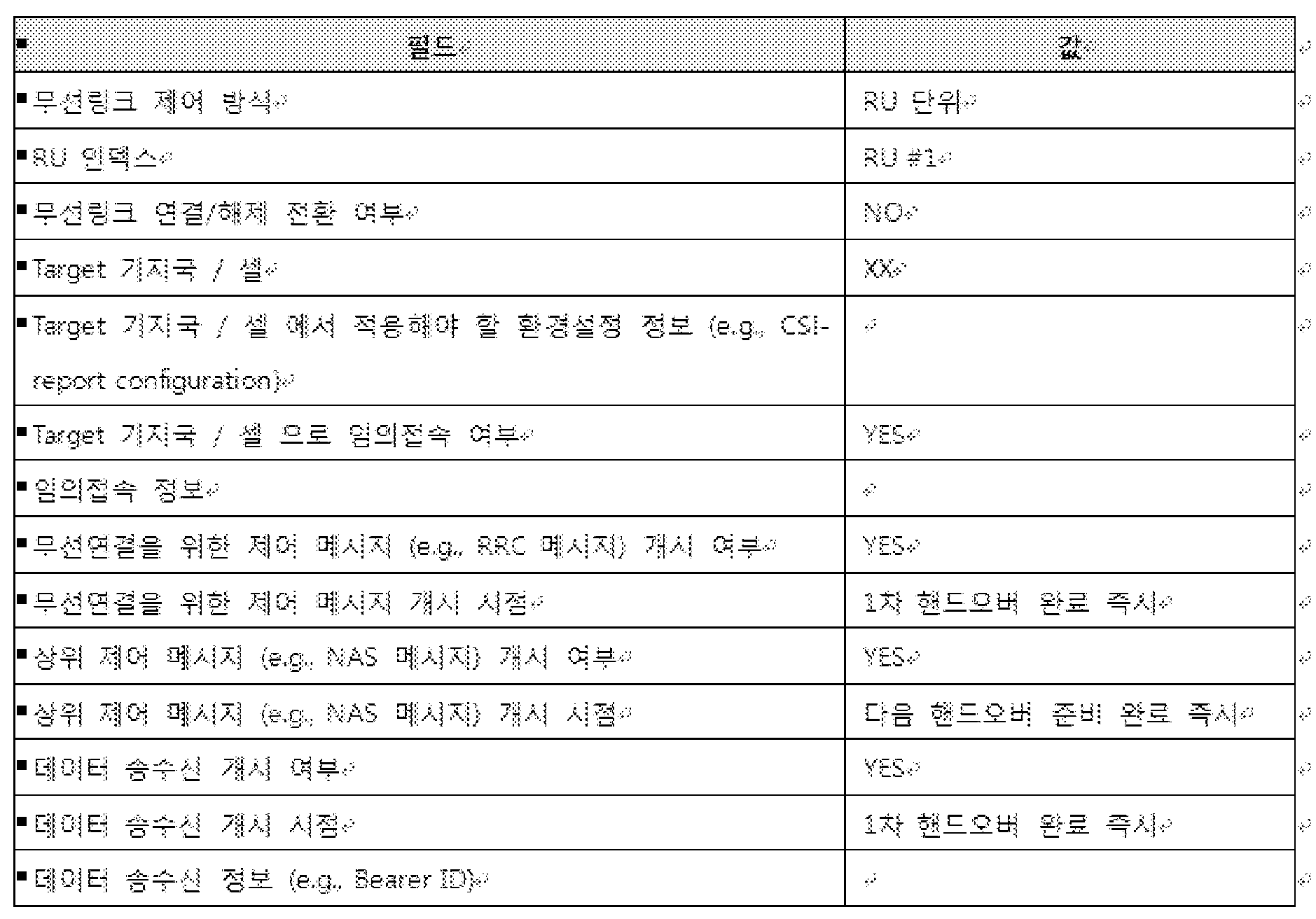
상기 설정 정보를 전송 받은 상기 단말은 이에 대한 응답으로 상기 RU 1(110) 또는 상기 RU 2(120)를 통해서 상기 서빙 기지국(200)으로 설정 완료 메시지를 전송한다(S21020).
상기 설정 완료 메시지를 전송한 경우, 상기 RU 1(110)은 상기 타겟 기지국과 상기 1 차 핸드오버를 위한 절차를 수행하기 때문에 상기 서빙 기지국은 상기 단말(100)의 RU 2(120)와만 제어 메시지 및 데이터를 송수신할 수 있다(S21030).
상기 S21030 단계와는 독립적으로 상기 RU 1(110)은 상기 타겟 기지국(300)과 1차 핸드오버 절차를 수행한다.
즉, 상기 RU 1(110)과 상기 타겟 기지국(300)은 앞에서 설명한 핸드오버를 위한 임의 접속 절차를 수행하여 상기 타겟 기지국(300)으로 핸드오버를 할 수 있다(S21040).
상기 임의 접속 절차가 완료 되면 상기 RU 1(110)은 상기 타겟 기지국으로 완료 메시지를 전송하여 핸드오버가 완료 되었음을 알린다(S21050).
이후, 상기 표 5에 도시된 바와 같이 무선연결을 위한 제어 메시지 개시 및 데이터 송수신의 개시 시점이 “1차 핸드오버 완료 즉시”라고 설정되어 있는바, 상기 RU 1(110) 및 상기 타겟 기지국(300)는 상기 1차 핸드오버가 완료된 뒤에 바로 무선 연결을 위한 제어 메시지 및 데이터를 송수신한다(S21060).
상기 RU 2(120)도 상기 RU 1(110)과 마찬가지로, 상기 기지국은 상기 RU 2(120)가 측정한 측정 정보에 기초하여 상기 RU 2(120)가 상기 타겟 기지국(300)의 커버리지로 이동하였다는 것을 인지하면, 상기 1차 핸드오버와 순차적으로 또는 독립적으로 상기 RU 2(120)와 상기 타겟 기지국으로의 핸드오버 절차(2차 핸드오버)를 수행할 수 있다.
상기 RU 2(120)에 대해 타겟 기지국(300)으로의 핸드오버를 결정한 상기 서빙 기지국(200)는 상기 타겟 기지국과 상기 RU 2(120)의 2차 핸드오버를 위한 정보(예를 들면, 상기 단말의 컨텍스트 정보, 능력 정보, 무선링크 제어 방식, 핸드오버를 수행하는 RU, 제어 메시지 및 데이터의 전송 개시 여부 및 전송 개시 시점, 환경설정 정보, 임의 접속을 위한 정보 등)를 교환한다.
이때, 상기 표 5에 도시된 바와 같이 상위 제어 메시지 개시 시점이 “다음 핸드오버 준비 완료 즉시”라고 설정되어 있는바, 상기 타겟 기지국(300)은 상기 서빙 기지국(200)과 상기 2차 핸드오버를 위한 정보의 송수신이 완료되면 상기 RU 1(110)과 상위 제어 메시지를 송수신할 수 있다.
이후, 상기 서빙 기지국(200)은 상기 2차 핸드오버를 위한 설정 정보를 상기 RU 2(120)에게 전송한다(S21070).
이 경우, 상기 RU 1(110)은 이미 상기 타겟 기지국으로의 핸드 오버가 완료된 상황이므로, 상기 설정 정보는 상기 RU 2(120)를 통해서 단말로 전송된다.
아래 표 6는 상기 2차 핸드오버를 위한 설정 정보의 일 예를 나타낸 표이다.

상기 설정 정보를 전송 받은 상기 단말은 이에 대한 응답으로 상기 RU 2(120)를 통해서 상기 서빙 기지국(200)으로 설정 완료 메시지를 전송한다(S21080).
상기 2차 핸드오버는 상기 RU 1(110)이 이미 상기 타겟 기지국으로 핸드오버를 수행하였기 때문에 별도의 임의 접속 절차 없이도 상기 RU 2(120)는 상기 타겟 기지국으로의 핸드오버가 가능할 수 있다.
즉, 상기 1차 핸드오버를 통해서 상기 단말(100)과 상기 타겟 기지국(300)간의 상향/하향링크 동기화가 이루어진 상태이기 때문에 별도의 임의 접속 절차가 수행되지 않아도 된다.
따라서, 상기 표 6에 도시된 설정 정보와 같이 상기 RU 2(120)는 상기 타겟 기지국(300)과 별도의 임의 접속 절차를 수행하지 않아도 핸드오버가 가능하며 상기 타겟 기지국으로 완료 메시지를 전송하여 상기 2 차 핸드오버가 완료 되었음을 알린다(S21090).
상기 1차 핸드오버 및 상기 2차 핸드오버를 통해서 상기 RU 1(110) 및 상기 RU 2(120) 모두 상기 타겟 기지국으로 이동하였기 때문에 상기 단말은 상기 RU 1(110) 및 상기 RU 2(120)를 통해서 상기 타겟 기지국과 제어 메시지 및 데이터를 송수신할 수 있다(S21100).
아래 표 7은 상기 1차 핸드오버 및 상기 2차 핸드오버에 따른 제어 메시지 및 데이터의 전송 가능 RU의 일 예를 나타낸 표이다.

도 22은 본 발명이 적용될 수 있는 단말에 포함된 다중 안테나가 각각 서로 다른 타겟 기지국으로 핸드오버 하는 방법의 일 예를 나타낸 흐름도이다.
상기 도 22를 참조하면, 서빙 기지국은 단말에 탑재된 다수 개의 분산된 무선 안테나를 개별적으로 제어하여 각각 서로 다른 타겟 기지국으로 핸드오버 하도록 제어할 수 있다.
먼저, 상기 도 21에서 단말(100)은 분산된 안테나인 RU 1(110) 및 RU 2(120)가 탑재되어 있고, 상기 RU 1(110) 및 상기 RU 2(120)의 primary cell은 동일하다고 가정한다.
하지만, 이러한 가정은 설명의 용이성을 위한 것일 뿐, 본 발명이 상기 가정에만 한정되는 것은 아니다.
구체적으로, 상기 단말(100)이 상기 도 20에 도시된 바와 같이 이동하는 경우, 상기 primary cell인 서빙 셀의 서빙 기지국(200)은 무선 유닛 단위로 상기 단말을 제어하기로 결정할 수 있다.
상기 RU 1(110)에 대해 타겟 기지국 2(400)으로의 핸드오버를 결정한 상기 서빙 기지국(200)는 상기 타겟 기지국 2(400)와 상기 RU 1(110)의 핸드오버(1차 핸드 오버)를 위한 정보(예를 들면, 상기 단말의 컨텍스트 정보, 능력 정보, 무선링크 제어 방식, 핸드오버를 수행하는 RU, 제어 메시지 및 데이터의 전송 개시 여부 및 전송 개시 시점, 환경설정 정보, 임의 접속을 위한 정보 등)를 교환한다.
이후, 상기 서빙 기지국(200)은 상기 1차 핸드오버를 위한 설정 정보를 상기 단말(100)에게 전송한다(S22010).
이때, 상기 RU 1(110) 및 상기 RU 2(120) 모두 상기 서빙 기지국(200)의 커버리지에 포함되어 있는 바, 상기 서빙 기지국(200)은 상기 RU 1(110) 및 상기 RU 2(120) 중 활성화되어 있는 무선 링크를 통해서 상기 설정 정보를 단말로 전송할 수 있다.
아래 표 8는 상기 1차 핸드오버를 위한 설정 정보의 일 예를 나타낸 표이다.

상기 설정 정보를 전송 받은 상기 단말(100)은 이에 대한 응답으로 상기 RU 1(110) 또는 상기 RU 2(120)를 통해서 상기 서빙 기지국(200)으로 설정 완료 메시지를 전송한다(S22020).
상기 설정 완료 메시지를 전송한 이후에 상기 서빙 기지국(200)은 상기 단말(100)의 RU 2(120)와만 제어 메시지 및 데이터를 송수신한다(S22030).
상기 S22030 단계와는 독립적으로 상기 RU 1(120)은 상기 타겟 기지국 2(400)와 1차 핸드오버 절차를 수행한다.
즉, 상기 RU 1(110)과 상기 타겟 기지국 2(400)는 앞에서 설명한 핸드오버를 위한 임의 접속 절차를 수행하여 상기 타겟 기지국 2(400)로 핸드오버를 할 수 있다(S22040).
상기 임의 접속 절차가 완료 되면 상기 RU 1(110)은 상기 타겟 기지국 2(400)로 완료 메시지를 전송하여 핸드오버가 완료 되었음을 알린다(S22050).
이후, 상기 표 8에 도시된 바와 같이 무선연결을 위한 제어 메시지 및 데이터 송수신의 개시 시점이 “1차 핸드오버 완료 즉시”라고 설정되어 있는바, 상기 RU 1(110) 및 상기 타겟 기지국 2(400)는 상기 1차 핸드오버가 완료된 뒤에 바로 무선 연결을 위한 제어 메시지 및 데이터를 송수신한다(S22060).
상기 RU 2(120)는 상기 RU 1(110)과는 다른 타겟 기지국으로 핸드오버를 수행하게 된다.
예를 들면, 상기 RU 2(120)와 상기 RU 1(110)이 각각 서로 다른 셀의 커버리지에 속하게 되거나, 다수 개의 셀 커버리지 서로 겹쳐진 영역에 속하게 되는경우, 상기 RU 2(120)는 상기 RU 1(110)과 다른 타겟 기지국으로 핸드오버를 할 수 있다.
즉, 상기 RU 2(120)는 상기 RU 1(110)과 독립적으로(또는 순서에 상관 없이) 상기 타겟 기지국 2(400)가 아닌 타겟 기지국 1(300)로 핸드오버를 수행할 수 있다.
상기 RU 2(120)의 타겟 기지국 1(300)로의 핸드오버를 결정한 상기 서빙 기지국(200)는 상기 타겟 기지국 1(300)과 상기 RU 2(120)의 2차 핸드오버를 위한 정보(예를 들면, 상기 단말의 컨텍스트 정보, 능력 정보, 무선링크 제어 방식, 핸드오버를 수행하는 RU, 제어 메시지 및 데이터의 전송 개시 여부 및 전송 개시 시점, 환경설정 정보, 임의 접속을 위한 정보 등)를 교환한다.
이후, 상기 서빙 기지국(200)은 상기 2차 핸드오버를 위한 설정 정보를 상기 RU 2(120)에게 전송한다(S22070).
이 경우, 상기 RU 1(110)은 이미 상기 타겟 기지국 2(400)로의 핸드 오버가 완료된 상황이므로, 상기 설정 정보는 상기 RU 2(120)를 통해서 단말로 전송된다.
아래 표 9는 상기 2차 핸드오버를 위한 설정 정보의 일 예를 나타낸 표이다.
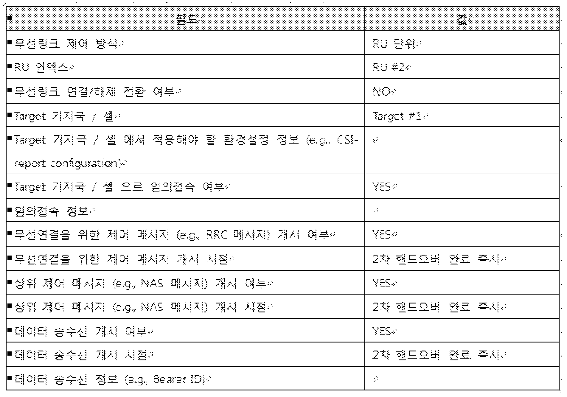
상기 설정 정보를 전송 받은 상기 RU 2(120)는 이에 대한 응답으로 상기 서빙 기지국(200)으로 설정 완료 메시지를 전송한다(S22080).
상기 RU 2(120)은 상기 1차 핸드오버와 같이 임의 접속 절차를 수행하여 상기 타겟 기지국 1(300)으로 핸드오버를 할 수 있다(S22090).
상기 임의 접속 절차가 완료 되면 상기 RU 2(120)은 상기 타겟 기지국 1(300)로 완료 메시지를 전송하여 핸드오버가 완료 되었음을 알린다(S22100).
이후, 상기 표 9에 도시된 바와 같이 무선연결을 위한 제어 메시지, 상위 계층의 제어 메시지(예를 들면, NAS 메시지) 및 데이터 송수신의개시 시점이 “2차 핸드오버 완료 즉시”라고 설정되어 있는바, 상기 RU 1(110) 및 상기 타겟 기지국(300)는 상기 2차 핸드오버가 완료된 뒤에 바로 제어 메시지 및 데이터를 송수신한다(S22110).
이와 같은 방법을 통해서 상기 서빙 기지국은 동일한 단말에 탑재된 다수의 분산된 다중 안테나를 각각 서로 다른 타겟 기지국으로 핸드오버하도록 제어할 수 있다.
도 23 및 도 24는 본 발명이 적용될 수 있는 단말에 포함된 다중 안테나가 각각 서로 다른 타겟 기지국으로 핸드오버 하는 방법의 일 예를 나타낸 도이다.
상기 도 23을 참조하면, 다수 개의 분산된 안테나가 탑재된 단말이 동시에 다수의 셀 커버리지에 포함되는 경우, 서빙 셀의 기지국은 상기 다수 개의 분산된 안테나를 개별적으로 제어하여 동일한 시점에 각각 서로 다른 타겟 셀의 기지국으로 핸드오버를 수행하도록 제어할 수 있다.
먼저, 상기 도 23 및 상기 도 24에서 단말(100)은 분산된 안테나인 RU 1(110) 및 RU 2(120)가 탑재되어 있고, 상기 RU 1(110) 및 상기 RU 2(120)의 primary cell은 동일하다고 가정한다.
하지만, 이러한 가정은 설명의 용이성을 위한 것일 뿐, 본 발명이 상기 가정에만 한정되는 것은 아니다.
구체적으로, 상기 도 23에 도시된 바와 같이 RU 1(110) 및 RU 2(120)가 탑재된 단말(100)이 서빙 셀의 커버리지에서 이동을 하여 타겟 셀 1 및 타겟 셀 2의 커버리지에 동시에 포함되는 경우, 상기 서빙 셀의 서빙 기지국은 상기 RU 1(110)을 상기 타겟 셀 2의 타겟 기지국(타겟 기지국 2)으로 상기 RU 2(120)를 상기 타겟 셀 1의 타겟 기지국(타겟 기지국 1)으로 핸드오버 하도록 제어할 수 있다.
상기 RU 1(110)의 상기 타겟 기지국 2(400)로의 핸드오버, 상기 RU 2(120)의 상기 타겟 기지국 1(300)로의 핸드오버를 결정한 상기 서빙 기지국(200)은 각각의 타겟 기지국과 각각의 핸드오버(이하, 제 1 핸드오버, 제 2 핸드오버라 호칭 함)를 위한 정보(예를 들면, 상기 단말의 컨텍스트 정보, 능력 정보, 무선링크 제어 방식, 핸드오버를 수행하는 RU, 제어 메시지 및 데이터의 전송 개시 여부 및 전송 개시 시점, 환경설정 정보, 임의 접속을 위한 정보 등)를 교환한다(S24010).
이후, 상기 서빙 기지국은 상기 제 1 핸드오버 및 상기 제 2 핸드오버를 위한 설정 정보를 상기 단말(100)로 전송한다(S24020).
이때, 상기 RU 1(110) 및 상기 RU 2(120) 모두 상기 서빙 기지국(200)의 커버리지에 포함되어 있는 바, 상기 서빙 기지국(200)은 상기 RU 1(110) 및 상기 RU 2(120) 중 활성화되어 있는 무선 링크를 통해서 상기 설정 정보를 단말로 전송할 수 있다.
아래 표 10은 상기 설정 정보의 일 예를 나타낸 표이다.

상기 설정 정보를 전송 받은 상기 단말(100)은 이에 대한 응답으로 상기 RU 1(110) 또는 상기 RU 2(120)를 통해서 상기 서빙 기지국(200)으로 설정 완료 메시지를 전송한다(S24030).
상기 설정 정보에 기초하여 상기 RU 1(110)은 상기 타겟 기지국 2(400)와 상기 제 1 핸드오버를 수행하고, 상기 RU 2(120)는 타겟 기지국 1(300)과 상기 제 2 핸드오버를 수행하게 된다.
즉, 상기 RU 1(110)는 상기 타겟 기지국 2(400)과 핸드오버를 위한 임의 접속 절차를 수행하여 상기 타겟 기지국 2(400)로 핸드오버를 하고, 상기 RU 2(120)는 상기 타겟 기지국 1(300)과 앞에서 설명한 핸드오버를 위한 임의 접속 절차를 수행하여 상기 타겟 기지국 1(300)로 핸드오버를 한다(S24040).
상기 제 1 핸드오버를 위한 임의 접속 절차가 완료 되면 상기 RU 1(110)은 상기 타겟 기지국 2(400)로 완료 메시지를 전송하여 핸드오버가 완료 되었음을 알린다(S24050).
이후, 상기 표 10에 도시된 바와 같이 무선연결을 위한 제어 메시지 및 데이터 송수신의 개시 시점이 “제 1 핸드오버 완료 즉시”라고 설정되어 있는바, 상기 RU 1(110) 및 상기 타겟 기지국 2(400)는 상기 제 1 핸드오버가 완료된 뒤에 바로 무선 연결을 위한 제어 메시지 및 데이터를 송수신한다(S24060).
마찬가지로, 상기 제 2 핸드오버를 위한 임의 접속 절차가 완료 되면 상기 RU 2(120)는 상기 타겟 기지국 1(300)로 완료 메시지를 전송하여 핸드오버가 완료 되었음을 알린다(S24070).
이후, 상기 표 10에 도시된 바와 같이 무선연결을 위한 제어 메시지, 상위 계층 제어 메시지(예를 들면, NAS 메시지 등) 및 데이터 송수신의 개시 시점이 “제 2 핸드오버 완료 즉시”라고 설정되어 있는바, 상기 RU 2(120) 및 상기 타겟 기지국 1(300)은 상기 제 2 핸드오버가 완료된 뒤에 바로 제어 메시지 및 데이터를 송수신한다(S24080).
이때, 상기 S24050 단계 및 상기 S24060 단계는 상기 S24070 단계 및 상기 S24080 단계와 동시에 또는 독립적으로 수행될 수 있다.
본 발명의 또 다른 실시 예로 상기 도 21 내지 상기 도 24에서 설명한 기지국 간의 핸드오버는 동일 기지국 내의 셀 간 핸드오버에도 적용될 수 있다. 따라서, 기지국은 동일하거나 다른 시점에서 동일하거나 다른 셀로의 핸드오버를 위한 무선링크 및 무선 연결의 설정을 각 RU 단위로 제어할 수 있다.
도 25는 본 발명이 적용될 수 있는 무선 장치의 내부 블록도의 일 예를 나타낸 도이다.
여기서, 상기 무선 장치는 기지국 및 단말일 수 있으며, 기지국은 매크로 기지국 및 스몰 기지국을 모두 포함한다.
상기 도 25에 도시된 바와 같이, 기지국(2510) 및 UE(2520)는 통신부(송수신부, RF 유닛, 2513, 2523), 프로세서(2511, 2521) 및 메모리(2512, 2522)를 포함한다.
이외에도 상기 기지국 및 UE는 입력부 및 출력부를 더 포함할 수 있다.
상기 통신부(2513, 2523), 프로세서(2511, 2521), 입력부, 출력부 및 메모리(2512, 2522)는 본 명세서에서 제안하는 방법을 수행하기 위해 기능적으로 연결되어 있다.
통신부(송수신부 또는 RF 유닛, 2513,2523)는 PHY 프로토콜(Physical Layer Protocol)로부터 만들어진 정보를 수신하면, 수신한 정보를 RF 스펙트럼(Radio-Frequency Spectrum)으로 옮기고, 필터링(Filtering), 증폭(Amplification) 등을 수행하여 안테나로 송신한다. 또한, 통신부는 안테나에서 수신되는 RF 신호(Radio Frequency Signal)을 PHY 프로토콜에서 처리 가능한 대역으로 옮기고, 필터링을 수행하는 기능을 한다.
그리고, 통신부는 이러한 송신과 수신 기능을 전환하기 위한 스위치(Switch) 기능도 포함할 수 있다.
또한 본 발명에서 상기 단말(2520)은 상기 통신부(2523)를 적어도 한 개 이상 포함할 수 있다.
프로세서(2511,2521)는 본 명세서에서 제안된 기능, 과정 및/또는 방법을 구현한다. 무선 인터페이스 프로토콜의 계층들은 프로세서에 의해 구현될 수 있다.
상기 프로세서는 제어부, controller, 제어 유닛, 컴퓨터 등으로 표현될 수도 있다.
메모리(2512,2522)는 프로세서와 연결되어, 상향링크 자원 할당 방법을 수행하기 위한 프로토콜이나 파라미터를 저장한다.
프로세서(2511,2521)는 ASIC(application-specific integrated circuit), 다른 칩셋, 논리 회로 및/또는 데이터 처리 장치를 포함할 수 있다. 메모리는 ROM(read-only memory), RAM(random access memory), 플래쉬 메모리, 메모리 카드, 저장 매체 및/또는 다른 저장 장치를 포함할 수 있다. 통신부는 무선 신호를 처리하기 위한 베이스밴드 회로를 포함할 수 있다. 실시 예가 소프트웨어로 구현될 때, 상술한 기법은 상술한 기능을 수행하는 모듈(과정, 기능 등)로 구현될 수 있다.
모듈은 메모리에 저장되고, 프로세서에 의해 실행될 수 있다. 메모리는 프로세서 내부 또는 외부에 있을 수 있고, 잘 알려진 다양한 수단으로 프로세서와 연결될 수 있다.
출력부(디스플레이부 또는 표시부)는 프로세서에 의해 제어되며, 키 입력부에서 발생되는 키 입력 신호 및 프로세서로부터의 각종 정보 신호와 함께, 상기 프로세서에서 출력되는 정보들을 출력한다.
나아가, 설명의 편의를 위하여 각 도면을 나누어 설명하였으나, 각 도면에 서술되어 있는 실시 예들을 병합하여 새로운 실시 예를 구현하도록 설계하는 것도 가능하다. 그리고, 당업자의 필요에 따라, 이전에 설명된 실시 예들을 실행하기 위한 프로그램이 기록되어 있는 컴퓨터에서 판독 가능한 기록 매체를 설계하는 것도 본 발명의 권리범위에 속한다.
본 명세서에 따른 방향 기반 기기 검색 방법은 상기한 바와 같이 설명된 실시 예들의 구성과 방법이 한정되게 적용될 수 있는 것이 아니라, 상기 실시 예들은 다양한 변형이 이루어질 수 있도록 각 실시 예들의 전부 또는 일부가 선택적으로 조합되어 구성될 수도 있다.
한편, 본 명세서의 방향 기반 기기 검색 방법은 네트워크 디바이스에 구비된 프로세서가 읽을 수 있는 기록매체에 프로세서가 읽을 수 있는 코드로서 구현하는 것이 가능하다. 프로세서가 읽을 수 있는 기록매체는 프로세서에 의해 읽혀질 수 있는 데이터가 저장되는 모든 종류의 기록장치를 포함한다. 프로세서가 읽을 수 있는 기록 매체의 예로는 ROM, RAM, CD-ROM, 자기 테이프, 플로피디스크, 광 데이터 저장장치 등이 있으며, 또한, 인터넷을 통한 전송 등과 같은 캐리어 웨이브의 형태로 구현되는 것도 포함한다. 또한, 프로세서가 읽을 수 있는 기록매체는 네트워크로 연결된 컴퓨터 시스템에 분산되어, 분산방식으로 프로세서가 읽을 수 있는 코드가 저장되고 실행될 수 있다.
또한, 이상에서는 본 명세서의 바람직한 실시 예에 대하여 도시하고 설명하였지만, 본 명세서는 상술한 특정의 실시 예에 한정되지 아니하며, 청구범위에서 청구하는 본 발명의 요지를 벗어남이 없이 당해 발명이 속하는 기술분야에서 통상의 지식을 가진 자에 의해 다양한 변형실시가 가능한 것은 물론이고, 이러한 변형실시들은 본 발명의 기술적 사상이나 전망으로부터 개별적으로 이해돼서는 안 될 것이다.
그리고, 당해 명세서에서는 물건 발명과 방법 발명이 모두 설명되고 있으며, 필요에 따라 양 발명의 설명은 보충적으로 적용될 수가 있다.
본 발명의 무선 통신 시스템에서 RRC 연결 방법은 3GPP LTE/LTE-A 시스템에 적용되는 예를 중심으로 설명하였으나, 3GPP LTE/LTE-A 시스템 이외에도 다양한 무선 통신 시스템에 적용하는 것이 가능하다.
Claims (15)
- 무선 통신 시스템에서 디바이스가 측정을 수행하는 방법에 있어서,기지국으로부터 상기 디바이스의 능력 정보(capability information)를 요청하는 요청 메시지를 수신하는 단계;상기 기지국으로 상기 능력 정보를 포함하는 응답 메시지를 전송하는 단계;상기 능력 정보에 기초하여 상기 디바이스에 포함된 2개 이상의 무선 유닛(radio unit)에 대한 측정 설정을 위한 제 1 설정 정보를 수신하는 단계,상기 무선 유닛은 신호의 송수신 및 신호 세기의 측정을 개별적으로 수행할 수 있는 유닛을 나타내고,상기 다수의 무선 유닛을 통해서 서빙 셀 및 인접 셀(neighbor cell)들을 측정하는 단계; 및상기 기지국으로 상기 서빙 셀 및 상기 인접 셀(neighbor cell)들의 측정된 측정 정보를 포함하는 보고 메시지를 전송하는 단계를 포함하는 방법.
- 제 1 항에 있어서,상기 능력 정보는 무선 접속 기술(radio access technology, RAT) 타입, 상기 디바이스가 다수의 무선 유닛을 포함하고 있는지 여부, 무선 유닛의 개수, 각각의 무선 유닛과 관련된 정보 중 적어도 하나를 포함하는 방법.
- 제 2 항에 있어서,상기 정보는 상기 무선 유닛의 인덱스, 무선링크 또는 무선연결의 활성화 여부, 카테고리, 물리계층 또는 무선 주파수(Radio Frequency, RF) 파라미터 중 적어도 하나를 포함하는 방법.
- 제 1 항에 있어서,상기 설정 정보는 각각의 무선 유닛에 대한 측정정보를 기지국으로 전송하기 위한 조건, 측정 정보의 전송 주기, 간격, 또는 상기 측정 정보를 다른 무선 유닛의 측정 정보와 같이 전송할 것인지 여부 중 적어도 하나를 포함하는 방법.
- 제 1 항에 있어서,상기 보고 메시지는 각각의 무선 유닛에 의해서 개별적으로 전송되는 방법.
- 제 1 항에 있어서,상기 보고 메시지는 상기 2개 이상의 무선 유닛 중 하나에 의해서 전송되며,상기 측정 정보는 각각의 무선 유닛에 대한 인덱스 및 상기 인덱스에 따른 측정 값을 포함하는 방법.
- 제 1 항에 있어서,상기 2개 이상의 무선 유닛 중 일부 무선 유닛은 무선 링크 연결 상태이고, 나머지 무선 유닛은 무선 링크 해제 상태인 방법.
- 제 1 항에 있어서,상기 측정 정보에 기초하여 상기 인접 셀들 중 적어도 하나의 타겟 셀로 핸드오버를 수행하는 단계를 더 포함하는 방법.
- 제 8 항에 있어서,상기 2개 이상의 무선 유닛이 상기 적어도 하나의 타겟 셀 중 동일한 타겟 셀로 핸드오버를 수행하는 방법.
- 제 9 항에 있어서,상기 핸드오버를 수행하는 단계는 상기 기지국으로부터 상기 타겟 셀과의 무선 연결을 위한 제 2 설정 정보를 수신하는 단계를 더 포함하되,상기 제 2 설정 정보는 상기 2개 이상의 무선 유닛에 대한 제어 방식, 무선 링크의 연결 상태로 전환될 무선 유닛에 대한 인덱스, 무선 링크의 해제 상태로 전환될 무선 유닛에 대한 인덱스, 타겟 셀 정보, 임의 접속 정보 또는 각각의 무선 유닛을 위한 환경 설정 정보 중 적어도 하나를 포함하는 방법.
- 제 9 항에 있어서,상기 핸드오버를 수행하는 단계는 상기 2 개 이상의 무선 유닛 중 하나의 무선 유닛이 상기 타겟 셀과 임의 접속 절차를 수행하는 단계를 더 포함하되,상기 2 개 이상의 무선 유닛 중 나머지 무선 유닛은 상기 타겟 셀과 임의 접속 절차를 수행하지 않는 방법.
- 제 1 항에 있어서,상기 측정 정보에 기초하여 상기 2개 이상의 무선 유닛 중 제 1 무선 유닛은 제 1 타겟 셀로 핸드오버를 수행하는 단계; 및상기 측정 정보에 기초하여 상기 2개 이상의 무선 유닛 중 제 2 무선 유닛은 제 2 타겟 셀로 핸드오버를 수행하는 단계를 더 포함하는 방법.
- 제 12 항에 있어서,상기 제 1 타겟 셀로 핸드오버를 수행하는 단계는 상기 제 1 타겟 셀과의 무선 연결을 위한 제 2 설정 정보를 수신하는 단계를 더 포함하되,상기 제 2 설정 정보는 상기 2개 이상의 무선 유닛에 대한 제어 방식, 무선 링크의 연결 상태로 전환될 무선 유닛에 대한 인덱스, 무선 링크의 해제 상태로 전환될 무선 유닛에 대한 인덱스, 타겟 셀 정보, 임의 접속 정보, 상기 무선 연결을 위한 제어 메시지의 개시 여부, 상기 제어 메시지의 전송 시점, 상기 제 1 타겟 셀과의 데이터 송수신 개시 여부, 상기 데이터 송수신의 개시 시점 또는 상기 데이터 송수신을 위한 정보 중 적어도 하나를 포함하는 방법.
- 제 12 항에 있어서,상기 제 2 타겟 셀로 핸드오버를 수행하는 단계는 상기 제 2 타겟 셀과의 무선 연결을 위한 제 2 설정 정보를 상기 제 2 무선 유닛을 통해서 수신하는 단계를 더 포함하되,상기 제 2 설정 정보는 상기 2개 이상의 무선 유닛에 대한 제어 방식, 무선 링크의 연결 상태로 전환될 무선 유닛에 대한 인덱스, 무선 링크의 해제 상태로 전환될 무선 유닛에 대한 인덱스, 타겟 셀 정보, 임의 접속 정보, 상기 무선 연결을 위한 제어 메시지의 개시 여부, 상기 제어 메시지의 전송 시점, 상기 제 2 타겟 셀과의 데이터 송수신 개시 여부, 상기 데이터 송수신의 개시 시점 또는 상기 데이터 송수신을 위한 정보 중 적어도 하나를 포함하는 방법.
- 무선 통신 시스템에서 측정을 수행하기 위한 장치에 있어서,외부와 무선 신호의 송수신 및 신호 세기의 측정을 개별적으로 수행할 수 있는 2개 이상의 무선 유닛; 및상기 2개 이상의 무선 유닛을 제어하기 위해 기능적으로 결합되어 있는 프로세서를 포함하되, 상기 프로세서는,기지국으로부터 상기 디바이스의 능력 정보(capability information)를 요청하는 요청 메시지를 수신하고,상기 기지국으로 상기 능력 정보를 포함하는 응답 메시지를 전송하며,상기 능력 정보에 기초하여 상기 디바이스에 포함된 2개 이상의 무선 유닛(radio unit)에 대한 측정 설정을 위한 제 1 설정 정보를 수신하고,상기 다수의 무선 유닛을 통해서 서빙 셀 및 인접 셀(neighbor cell)들을 측정하며,상기 기지국으로 상기 서빙 셀 및 상기 인접 셀(neighbor cell)들의 측정된 측정 정보를 포함하는 보고 메시지를 전송하는 장치.
Priority Applications (3)
| Application Number | Priority Date | Filing Date | Title |
|---|---|---|---|
| PCT/KR2016/015243 WO2018117313A1 (ko) | 2016-12-23 | 2016-12-23 | 무선 통신 시스템에서 단말의 무선 링크 및 무선 연결을 제어하기 위한 방법 및 이를 지원하는 장치 |
| US16/473,221 US11070996B2 (en) | 2016-12-23 | 2016-12-23 | Method for controlling wireless link and wireless connection of terminal in wireless communication system, and apparatus supporting same |
| EP16924599.0A EP3562198B1 (en) | 2016-12-23 | 2016-12-23 | Method for controlling wireless link and wireless connection of terminal in wireless communication system, and apparatus supporting same |
Applications Claiming Priority (1)
| Application Number | Priority Date | Filing Date | Title |
|---|---|---|---|
| PCT/KR2016/015243 WO2018117313A1 (ko) | 2016-12-23 | 2016-12-23 | 무선 통신 시스템에서 단말의 무선 링크 및 무선 연결을 제어하기 위한 방법 및 이를 지원하는 장치 |
Publications (1)
| Publication Number | Publication Date |
|---|---|
| WO2018117313A1 true WO2018117313A1 (ko) | 2018-06-28 |
Family
ID=62627495
Family Applications (1)
| Application Number | Title | Priority Date | Filing Date |
|---|---|---|---|
| PCT/KR2016/015243 WO2018117313A1 (ko) | 2016-12-23 | 2016-12-23 | 무선 통신 시스템에서 단말의 무선 링크 및 무선 연결을 제어하기 위한 방법 및 이를 지원하는 장치 |
Country Status (3)
| Country | Link |
|---|---|
| US (1) | US11070996B2 (ko) |
| EP (1) | EP3562198B1 (ko) |
| WO (1) | WO2018117313A1 (ko) |
Cited By (2)
| Publication number | Priority date | Publication date | Assignee | Title |
|---|---|---|---|---|
| CN111031560A (zh) * | 2019-12-26 | 2020-04-17 | 重庆邮电大学 | 一种基于环境预判的业务优化方法 |
| WO2023286984A1 (ko) * | 2021-07-14 | 2023-01-19 | 삼성전자 주식회사 | 인터 라디오 엑세스 기술의 측정 오브젝트에 대한 측정을 수행하는 전자 장치 및 그 동작 방법 |
Families Citing this family (16)
| Publication number | Priority date | Publication date | Assignee | Title |
|---|---|---|---|---|
| CN108282828B (zh) * | 2017-01-06 | 2019-09-17 | 电信科学技术研究院 | 一种位置管理方法及装置 |
| US10880793B2 (en) * | 2017-01-16 | 2020-12-29 | Telefonaktiebolaget Lm Ericsson (Publ) | Link switch in a wireless communication system |
| JP6949969B2 (ja) * | 2017-01-23 | 2021-10-13 | オッポ広東移動通信有限公司Guangdong Oppo Mobile Telecommunications Corp., Ltd. | ランダムアクセスのための方法、端末装置及びネットワーク機器 |
| ES2882150T3 (es) * | 2017-03-24 | 2021-12-01 | Ericsson Telefon Ab L M | RLM y detección de fallos de haz basándose en una mezcla de diferentes señales de referencia |
| GB2566965A (en) * | 2017-09-28 | 2019-04-03 | Samsung Electronics Co Ltd | Improvements in and relating to connection setup |
| US10716096B2 (en) * | 2017-11-07 | 2020-07-14 | Apple Inc. | Enabling network slicing in a 5G network with CP/UP separation |
| EP4156823A1 (en) * | 2018-01-11 | 2023-03-29 | FG Innovation Company Limited | Uplink carrier configuration and selection with supplementary uplink |
| US10667185B2 (en) * | 2018-03-28 | 2020-05-26 | Telefonaktiebolaget Lm Ericsson (Publ) | Method for avoiding unnecessary actions in resume procedure |
| ES2952283T3 (es) * | 2018-05-10 | 2023-10-30 | Beijing Xiaomi Mobile Software Co Ltd | Métodos para adquirir y enviar información de ruta de vehículo aéreo no tripulado |
| WO2020168112A1 (en) * | 2019-02-13 | 2020-08-20 | Apple Inc. | Self-organizing networks (son) for mobility robustness optimization (mro) and automatic network slice creation |
| US11122503B2 (en) * | 2019-02-14 | 2021-09-14 | Lg Electronics Inc. | Method and apparatus for inter-RAT cell selection mechanism in NB-IOT |
| CN114128350A (zh) | 2019-03-29 | 2022-03-01 | 三星电子株式会社 | 无线通信网络中执行条件切换的方法和装置 |
| WO2021015553A1 (en) * | 2019-07-22 | 2021-01-28 | Lg Electronics Inc. | Method and apparatus for cell reselection in wireless communication system |
| US20230171655A1 (en) * | 2020-04-30 | 2023-06-01 | Google Llc | Method Network Optimization in Handover Failure Scenarios |
| CN113938915A (zh) * | 2020-07-13 | 2022-01-14 | 华为技术有限公司 | 一种通信方法和装置 |
| WO2022021373A1 (zh) * | 2020-07-31 | 2022-02-03 | 华为技术有限公司 | 一种通信方法及装置 |
Citations (5)
| Publication number | Priority date | Publication date | Assignee | Title |
|---|---|---|---|---|
| US20130242796A1 (en) * | 2011-01-06 | 2013-09-19 | Zte Corporation | Method for reporting measurement capability and UE |
| US20140226623A1 (en) * | 2011-08-19 | 2014-08-14 | Lg Electronics Inc. | Method and apparatus for performing handover in wireless communication system |
| US20140357275A1 (en) * | 2013-02-27 | 2014-12-04 | Huawei Technologies Co., Ltd. | Cell handover method, user equipment and base station |
| US20150043367A1 (en) * | 2012-03-18 | 2015-02-12 | Lg Electronics Inc. | Method and apparatus for transmitting neighbor-cell measurement command in wireless communication system |
| WO2016163841A1 (ko) * | 2015-04-10 | 2016-10-13 | 엘지전자(주) | 무선 통신 시스템에서 채널 상태 정보를 보고하기 위한 방법 및 이를 위한 장치 |
Family Cites Families (9)
| Publication number | Priority date | Publication date | Assignee | Title |
|---|---|---|---|---|
| KR100651447B1 (ko) * | 2004-04-14 | 2006-11-29 | 삼성전자주식회사 | 복수의 안테나들을 사용하는 셀룰러 이동통신 시스템에서의 안테나 재 선택 시스템 및 방법 |
| KR101002879B1 (ko) * | 2005-06-10 | 2010-12-21 | 삼성전자주식회사 | 이동 통신 시스템에서의 핸드오프 방법 |
| EP2182754B1 (en) * | 2008-10-30 | 2014-01-15 | Telefonaktiebolaget LM Ericsson (publ) | Method and receiver for estimating and reporting a channel quality measure |
| PL2702796T3 (pl) | 2011-04-27 | 2019-05-31 | Nokia Solutions & Networks Oy | Poprawa mobilności małej komórki |
| CN105323041B (zh) * | 2011-07-12 | 2019-06-07 | 华为技术有限公司 | 一种小区测量方法、小区资源共享方法和相关设备 |
| EP4339794A1 (en) * | 2014-05-23 | 2024-03-20 | Huawei Technologies Co., Ltd. | Euicc management method, euicc, sm platform, and system |
| KR102585514B1 (ko) * | 2014-12-01 | 2023-10-10 | 삼성전자주식회사 | 통신 시스템에서 단말과 인접 액세스 포인트간 데이터 송수신 방법 및 그 장치 |
| US10582403B2 (en) * | 2015-07-20 | 2020-03-03 | Samsung Electronics Co., Ltd | Communication method and apparatus in wireless communication system |
| EP3419371A4 (en) * | 2016-03-23 | 2019-07-10 | Ntt Docomo, Inc. | USER UNIT, WIRELESS BASE STATION AND WIRELESS COMMUNICATION PROCESS |
-
2016
- 2016-12-23 EP EP16924599.0A patent/EP3562198B1/en active Active
- 2016-12-23 US US16/473,221 patent/US11070996B2/en active Active
- 2016-12-23 WO PCT/KR2016/015243 patent/WO2018117313A1/ko unknown
Patent Citations (5)
| Publication number | Priority date | Publication date | Assignee | Title |
|---|---|---|---|---|
| US20130242796A1 (en) * | 2011-01-06 | 2013-09-19 | Zte Corporation | Method for reporting measurement capability and UE |
| US20140226623A1 (en) * | 2011-08-19 | 2014-08-14 | Lg Electronics Inc. | Method and apparatus for performing handover in wireless communication system |
| US20150043367A1 (en) * | 2012-03-18 | 2015-02-12 | Lg Electronics Inc. | Method and apparatus for transmitting neighbor-cell measurement command in wireless communication system |
| US20140357275A1 (en) * | 2013-02-27 | 2014-12-04 | Huawei Technologies Co., Ltd. | Cell handover method, user equipment and base station |
| WO2016163841A1 (ko) * | 2015-04-10 | 2016-10-13 | 엘지전자(주) | 무선 통신 시스템에서 채널 상태 정보를 보고하기 위한 방법 및 이를 위한 장치 |
Non-Patent Citations (2)
| Title |
|---|
| "Evolved Universal Terrestrial Radio Access (E-UTRA) Radio Resource Control (RRC); Protocol specification (Release 8", 3GPP TS 36.331 V8.5.0, March 2009 (2009-03-01) |
| See also references of EP3562198A4 |
Cited By (3)
| Publication number | Priority date | Publication date | Assignee | Title |
|---|---|---|---|---|
| CN111031560A (zh) * | 2019-12-26 | 2020-04-17 | 重庆邮电大学 | 一种基于环境预判的业务优化方法 |
| CN111031560B (zh) * | 2019-12-26 | 2022-05-03 | 重庆邮电大学 | 一种基于环境预判的业务优化方法 |
| WO2023286984A1 (ko) * | 2021-07-14 | 2023-01-19 | 삼성전자 주식회사 | 인터 라디오 엑세스 기술의 측정 오브젝트에 대한 측정을 수행하는 전자 장치 및 그 동작 방법 |
Also Published As
| Publication number | Publication date |
|---|---|
| EP3562198A4 (en) | 2020-07-22 |
| EP3562198B1 (en) | 2021-08-04 |
| EP3562198A1 (en) | 2019-10-30 |
| US20190357065A1 (en) | 2019-11-21 |
| US11070996B2 (en) | 2021-07-20 |
Similar Documents
| Publication | Publication Date | Title |
|---|---|---|
| WO2018117313A1 (ko) | 무선 통신 시스템에서 단말의 무선 링크 및 무선 연결을 제어하기 위한 방법 및 이를 지원하는 장치 | |
| WO2017073844A1 (ko) | 무선통신 시스템에서 데이터를 송수신하기 위한 방법 및 장치 | |
| WO2018231028A1 (ko) | 무선 통신 시스템에서 단말의 등록 방법 및 이를 위한 장치 | |
| WO2017061643A1 (ko) | 무선 통신 시스템에서 기지국과 데이터를 송수신하는 방법 및 장치 | |
| WO2018009011A1 (en) | Method and apparatus for supporting handover of drone in wireless communication system | |
| WO2017111185A1 (ko) | 무선통신 시스템에서 데이터를 송수신하기 위한 방법 및 장치 | |
| WO2018174676A1 (ko) | 제 1 무선접속기술과 제 2 무선접속기술을 통해 데이터를 송수신하는 단말이 측정 결과를 보고하는 방법 및 장치 | |
| WO2018231029A1 (ko) | 무선 통신 시스템에서 단말의 등록 방법 및 이를 위한 장치 | |
| WO2018164552A1 (ko) | 무선 통신 시스템에서 릴레이를 통한 데이터 송수신 방법 및 이를 위한 장치 | |
| WO2019160342A1 (en) | Method and apparatus for supporting rach-less mobility with pre-allocated beams in wireless communication system | |
| WO2018131984A1 (ko) | 무선 통신 시스템에서 ue 설정 업데이트 방법 및 이를 위한 장치 | |
| WO2018128528A1 (ko) | 무선 통신 시스템에서 pdu 세션 관리 방법 및 이를 위한 장치 | |
| WO2018044144A1 (ko) | 무선 통신 시스템에서 서비스 요청 절차를 수행하기 위한 방법 및 이를 위한 장치 | |
| WO2018147698A1 (ko) | 무선 통신 시스템에서 nas 메시지 송수신 방법 및 이를 위한 장치 | |
| WO2016111591A1 (ko) | 무선 통신 시스템에서 페이징 전송 방법 및 이를 위한 장치 | |
| WO2016208997A1 (ko) | 무선 통신 시스템에서 단말의 영역 관리 방법 및 이를 위한 장치 | |
| WO2018236164A1 (ko) | 무선 통신 시스템에서 서비스 요청 절차 수행 방법 및 이를 위한 장치 | |
| WO2017039042A1 (ko) | 무선 통신 시스템에서 단말의 데이터 송수신 방법 및 장치 | |
| WO2016159699A1 (ko) | 무선 통신 시스템에서 단말에 의해 수행되는 통신 방법 및 상기 방법을 이용하는 단말 | |
| WO2016190687A1 (ko) | 무선 통신 시스템에서 단말에 의해 수행되는 링크 해제 방법 및 상기 방법을 이용하는 단말 | |
| WO2019054783A1 (ko) | 무선 통신 시스템에서 v2x 통신을 수행하기 방법 및 이를 위한 장치 | |
| WO2018079947A1 (ko) | 무선 통신 시스템에서 ue 이동성을 지원하기 위한 방법 및 이를 위한 장치 | |
| WO2019031865A1 (ko) | 무선 통신 시스템에서 rrc 연결 절차 수행 방법 및 이를 위한 장치 | |
| WO2016099138A1 (ko) | 무선 통신 시스템에서 페이징 전송 방법 및 이를 위한 장치 | |
| WO2016159522A1 (ko) | 네트워크 선택 및 트래픽 라우팅을 수행하는 방법 및 사용자 장치 |
Legal Events
| Date | Code | Title | Description |
|---|---|---|---|
| 121 | Ep: the epo has been informed by wipo that ep was designated in this application |
Ref document number: 16924599 Country of ref document: EP Kind code of ref document: A1 |
|
| NENP | Non-entry into the national phase |
Ref country code: DE |
|
| ENP | Entry into the national phase |
Ref document number: 2016924599 Country of ref document: EP Effective date: 20190723 |