WO2018110216A1 - パワーステアリング装置 - Google Patents
パワーステアリング装置 Download PDFInfo
- Publication number
- WO2018110216A1 WO2018110216A1 PCT/JP2017/041797 JP2017041797W WO2018110216A1 WO 2018110216 A1 WO2018110216 A1 WO 2018110216A1 JP 2017041797 W JP2017041797 W JP 2017041797W WO 2018110216 A1 WO2018110216 A1 WO 2018110216A1
- Authority
- WO
- WIPO (PCT)
- Prior art keywords
- power steering
- signal
- moisture
- housing
- abnormality determination
- Prior art date
- Legal status (The legal status is an assumption and is not a legal conclusion. Google has not performed a legal analysis and makes no representation as to the accuracy of the status listed.)
- Ceased
Links
Images


Classifications
-
- B—PERFORMING OPERATIONS; TRANSPORTING
- B62—LAND VEHICLES FOR TRAVELLING OTHERWISE THAN ON RAILS
- B62D—MOTOR VEHICLES; TRAILERS
- B62D5/00—Power-assisted or power-driven steering
- B62D5/04—Power-assisted or power-driven steering electrical, e.g. using an electric servo-motor connected to, or forming part of, the steering gear
-
- B—PERFORMING OPERATIONS; TRANSPORTING
- B62—LAND VEHICLES FOR TRAVELLING OTHERWISE THAN ON RAILS
- B62D—MOTOR VEHICLES; TRAILERS
- B62D6/00—Arrangements for automatically controlling steering depending on driving conditions sensed and responded to, e.g. control circuits
-
- F—MECHANICAL ENGINEERING; LIGHTING; HEATING; WEAPONS; BLASTING
- F16—ENGINEERING ELEMENTS AND UNITS; GENERAL MEASURES FOR PRODUCING AND MAINTAINING EFFECTIVE FUNCTIONING OF MACHINES OR INSTALLATIONS; THERMAL INSULATION IN GENERAL
- F16H—GEARING
- F16H25/00—Gearings comprising primarily only cams, cam-followers and screw-and-nut mechanisms
- F16H25/18—Gearings comprising primarily only cams, cam-followers and screw-and-nut mechanisms for conveying or interconverting oscillating or reciprocating motions
- F16H25/20—Screw mechanisms
-
- F—MECHANICAL ENGINEERING; LIGHTING; HEATING; WEAPONS; BLASTING
- F16—ENGINEERING ELEMENTS AND UNITS; GENERAL MEASURES FOR PRODUCING AND MAINTAINING EFFECTIVE FUNCTIONING OF MACHINES OR INSTALLATIONS; THERMAL INSULATION IN GENERAL
- F16H—GEARING
- F16H7/00—Gearings for conveying rotary motion by endless flexible members
- F16H7/02—Gearings for conveying rotary motion by endless flexible members with belts; with V-belts
Definitions
- the present invention relates to a power steering device.
- moisture detection elements are installed at both ends of a housing that houses a rack bar, and moisture intrusion into the housing is detected.
- One of the objects of the present invention is to provide a power steering device that can determine whether or not there is an abnormality in the device due to freezing of water that has entered the housing.
- the power steering device determines whether or not there is an abnormality in the power steering device based on a signal representing temperature information and an output signal of a moisture detecting element provided in the housing.
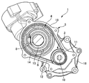
- FIG. 1 is an axial cross-sectional view of a power steering device 1 according to Embodiment 1.
- FIG. 2 is a cross-sectional view taken along arrow S1-S1 in FIG.
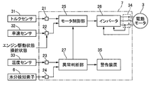
- FIG. 3 is a control block diagram of a control unit 7 according to the first embodiment. 3 is a flowchart illustrating a flow of abnormality determination processing by a control unit 7 according to the first embodiment.
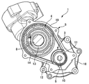
- FIG. 5 is a cross-sectional view taken along arrow S1-S1 in FIG. 6 is a flowchart showing a flow of abnormality determination processing by a control unit 7 of Embodiment 2. It is a figure which shows the switching method of the assist map in the abnormality determination process of Embodiment 2.
- 10 is a flowchart showing a flow of abnormality determination processing by a control unit 7 of Embodiment 4.
- FIG. 1 is a cross-sectional view in the axial direction of the power steering device 1 according to the first embodiment, and FIG.
- the power steering device 1 is mounted on a vehicle that uses an engine as a power source.
- the power steering apparatus 1 includes a steering mechanism 2, an electric motor 3, a ball screw mechanism (transmission mechanism) 4, a housing 5, and a moisture detection element 6.
- the steering mechanism 2 steers front wheels, which are steered wheels, and has a rack bar 8 extending in the vehicle body width direction.
- the rack bar 8 is formed using a ferrous metal material such as a steel material.
- the rack bar 8 moves in the vehicle body width direction according to the rotation of the steering shaft connected to the steering wheel (not shown).
- the ends of the pair of tie rods 9 and 9 are connected to both ends of the rack bar 8.
- a front wheel is connected to the pair of tie rods 9,9.
- the electric motor 3 applies a steering force to the steering mechanism 2.
- the electric motor 3 is, for example, a three-phase brushless motor.
- An input pulley 11 is attached to the motor shaft 10 of the electric motor 3.
- One end of an endless belt 12 is hung on the outer periphery of the input pulley 11.
- the ball screw mechanism 4 is provided between the steering mechanism 2 and the electric motor 3.
- the ball screw mechanism 4 converts the rotational force of the electric motor 3 into the propulsive force of the steering mechanism 2.
- the ball screw mechanism 4 has a nut 13.
- the nut 13 is formed in a substantially cylindrical shape and surrounds the rack bar 8.
- An output pulley 14 is fixed to the outer periphery of the nut 13.
- the outer diameter of the output pulley 14 is larger than the outer diameter of the input pulley 11.
- the other end of the endless belt 12 is hung on the outer periphery of the output pulley 14.
- the nut 13 is supported so as to be rotatable with respect to the housing 5 and immovable in the axial direction.
- a ball circulation groove 15 is formed on the inner periphery of the nut 13 and the outer periphery of the rack bar 8.
- a plurality of balls 16 are arranged in the ball circulation groove 15. The plurality of balls 16 move to one end side or the other end side of the ball circulation groove 15 according to the rotation of the nut 13.
- the ball 16 that has reached one end or the other end of the ball circulation groove 15 by the rotation of the nut 13 is returned to the other end or one end of the ball circulation groove 15 via a tube (not shown).
- the housing 5 is formed by die casting using an aluminum alloy.
- the housing 5 includes a steering mechanism housing portion 17, a motor housing portion (electric motor housing portion, control device housing portion) 18, and a ball screw mechanism housing portion (transmission mechanism housing portion) 19.
- the steering mechanism housing part 17 houses a part of the steering mechanism 2 (a part of the steering shaft, the rack bar 8, etc.).
- the inner ends of the dust boots 20 in the vehicle width direction are fixed to both ends of the steering mechanism housing portion 17 in the vehicle width direction.
- the dust boot 20 is formed in a bellows ring shape using rubber or the like.
- the outer end of the dust boot 20 in the vehicle width direction is fixed to the tie rod 9.
- the motor housing portion 18 houses the electric motor 3 therein.
- the ball screw mechanism accommodating portion 19 accommodates the ball screw mechanism 4 inside.
- the moisture detecting element 6 has a pair of metal terminals (electrodes) and outputs a signal of a resistance value between the pair of metal terminals.
- the moisture detecting element 6 is installed in the ball screw mechanism accommodating portion 19.
- the moisture detecting element 6 overlaps the nut 13 of the ball screw mechanism 4 in the vertical direction in a state where the housing 5 is mounted on the vehicle.
- the electric motor 3 is controlled by a control unit 7 (see FIG. 3) which is a control device.
- the control unit 7 is a control board on which a microcomputer is mounted.
- the control unit 7 is housed in the motor housing portion 18 together with the electric motor 3.
- the control unit 7 controls the output torque of the electric motor 3 based on the steering torque of the driver input to the steering mechanism 2, and performs assist control to reduce the driver's steering burden.
- FIG. 3 is a control block diagram of the control unit 7 of the first embodiment.
- the control unit 7 includes a steering torque signal receiving unit 21, an operation state signal receiving unit 22, a temperature information signal receiving unit 23, a moisture information signal receiving unit 24, a motor control unit 25, an inverter 26, and an abnormality determination unit 27.
- the steering torque signal receiving unit 21 receives a steering torque signal from a torque sensor 31 that detects the steering torque of the steering mechanism 2.
- the torque sensor 31 outputs a steering torque signal corresponding to the torsion bar twist amount of the steering shaft.
- the driving state signal receiving unit 22 receives a driving state signal of the vehicle.
- the vehicle driving state signals are a vehicle speed signal from the vehicle speed sensor 32, an engine driving state signal (engine speed signal or the like), and a steering state signal (steering angle signal or the like) of the steering mechanism 2.
- the temperature information signal receiving unit 23 receives temperature information from the temperature sensor 33 mounted on the control board of the control unit 7.
- the moisture information signal receiving unit 24 receives the output signal of the moisture detecting element 6.
- the motor control unit 25 generates a command current for the electric motor 3 from the vehicle speed signal and the steering torque signal.
- the motor control unit 25 determines the command current with reference to an assist map in which the command current for the steering torque signal is set in advance.
- the motor control unit 25 includes a plurality of types of assist maps, and switches assist maps to be referred to according to a vehicle speed signal. Specifically, an assist map having a characteristic that the change gradient of the command current with respect to the steering torque signal is gentler as the vehicle speed is higher is selected.
- the motor control unit 25 generates a three-phase voltage command for causing a command current to flow through the electric motor 3, and further generates a switching signal by comparing the three-phase voltage command with the triangular wave carrier signal.
- the inverter 26 is driven according to the switching signal and supplies a three-phase current to the electric motor 3.
- the phase current of each phase is detected by the current sensor 34.
- the abnormality determination unit 27 outputs the output signal of the temperature sensor 33, the output signal of the moisture detection element 6, the signal of the driving state of each vehicle (the output signal of the torque sensor 31, the vehicle speed sensor 32, etc.) and the output signal of the moisture detection element 6. input.
- the abnormality determination unit 27 of the first embodiment determines whether the power steering device 1 is abnormal based on the output signals of the temperature sensor 33 and the moisture detection element 6. Abnormality refers to a state in which a malfunction occurs in the power steering device 1 due to freezing of water that has entered the housing 5 or a condition in which a malfunction is likely to occur.
- the abnormality determination unit 27 outputs a warning signal to the warning device 35 when determining that there is an abnormality.
- a warning signal is output, the warning device 35 turns on a warning lamp to notify the driver of the abnormality. At this time, a warning sound may be sounded. If the abnormality determination unit 27 determines that there is an abnormality, the command current of the electric motor 3 is set to 0 and the assist control is prohibited.
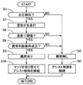
- FIG. 4 is a flowchart showing the flow of abnormality determination processing by the control unit 7 of the first embodiment. This process is repeatedly executed at a predetermined control period while the ignition switch (vehicle start switch) is on.
- the abnormality determination unit 27 determines whether moisture has been detected in the ball screw mechanism housing unit 19 based on the output signal of the moisture detection element 6 received by the moisture information signal receiving unit 24. If YES, the process proceeds to step S1, and if NO, the process proceeds to step S4.
- step S2 the abnormality determination unit 27 estimates the temperature in the ball screw mechanism housing unit 19 from the temperature information signal from the temperature sensor 33 received by the temperature information signal reception unit 23, and the estimated temperature is determined as the freezing determination threshold ( It is determined whether the temperature is predicted to freeze water, for example, below 0 ° C. If YES, the process proceeds to step S3. If NO, the process proceeds to step S4. In this step, first, the temperature information signal is subjected to filter processing by, for example, a first-order low-pass filter. The time constant of the low-pass filter is set in consideration of the delay factor of the change in the frozen state with respect to the temperature change.
- the temperature in the ball screw mechanism accommodating portion 19 is estimated by reducing and correcting the temperature indicated by the signal after filtering.
- the correction amount is set according to a temperature change (for example, the electric motor 3) in the motor housing portion 18.
- the estimated temperature is compared with the freezing judgment threshold.
- the abnormality determination unit 27 determines that “abnormality exists”.
- the abnormality determination unit 27 determines “no abnormality”.
- the abnormality determination unit 27 prohibits assist control and turns on a warning lamp.
- the motor control unit 25 sets the command current of the electric motor 3 to 0 while the assist control is prohibited.
- the command current may be gradually reduced to 0 in order to suppress a sudden change in steering torque.
- the command current may be set to 0 after waiting for the vehicle speed to sufficiently decrease.
- the motor control unit 25 continues assist control.
- Embodiment 1 In a power steering apparatus, water such as rainwater and muddy water may enter the housing that houses the rack bar due to damage to the dust boots.
- the power steering function is not affected only by moisture entering the housing.
- the power steering apparatus 1 malfunctions due to freezing of moisture, there is a risk of steering lock. For this reason, appropriate judgment is required as to whether or not the assist control can be continued, whether or not the warning signal can be output, or the timing thereof.
- the abnormality determination unit 27 has entered the housing 5 based on the temperature information signal and the output signal of the moisture detecting element 6 installed in the housing 5. It is determined whether or not the power steering apparatus 1 is abnormal due to moisture freezing.
- the intrusion of moisture into the housing 5 can be detected from the output signal of the moisture detecting element 6.
- the freezing of moisture in the housing 5 can be determined from the temperature information signal. Therefore, the power steering device 1 according to the first embodiment can determine whether or not the power steering device 1 is abnormal due to the freezing of the moisture that has entered the housing 5. Thereby, it is possible to appropriately determine whether the assist control can be continued, whether the warning signal can be output, or the timing thereof.
- the abnormality determination unit 27 determines that there is no abnormality and continues assist control when the possibility that the water is frozen is low. On the other hand, when the possibility of freezing is high, it is determined that there is an abnormality, and assist control is prohibited and a warning is given to the driver. Since the power steering function is not affected only by moisture entering the housing 5, in this case, the convenience of the driver can be maintained by continuing the assist control. On the other hand, when the water in the housing 5 is frozen, the power steering function is hindered. In this case, the safety can be improved by prohibiting the assist control. Therefore, in the power steering apparatus 1 of the first embodiment, it is possible to realize both maintenance of the driver's convenience and improvement of safety.
- the temperature sensor 33 that acquires temperature information is installed in the motor housing portion 18 that houses the control unit 7. Since the temperature sensor 33 and the control unit 7 are in the same space (in the motor housing portion 18), the connection between the temperature sensor 33 and the control unit 7 can be facilitated.
- the abnormality determination unit 27 further considers a delay factor with respect to the change in the temperature information signal, and determines whether the moisture in the housing 5 is frozen. Even if the ambient temperature reaches the freezing temperature, there is a delay before the water actually becomes frozen, so the abnormality determination accuracy of the power steering device 1 is improved by determining whether there is an abnormality taking this delay into account. it can.
- the abnormality determination unit 27 corrects the temperature information signal obtained from the temperature sensor 33 in accordance with the temperature change in the motor housing unit 18.
- the temperature of the motor housing 18 in which the temperature sensor 33 is installed is affected by the heat generated by the inverter 26 and the microprocessor. For this reason, the temperature detected by the temperature sensor 33 may be higher than the temperature in the ball screw mechanism housing portion 19.
- the temperature of the ball screw mechanism housing portion 19 can be accurately estimated by correcting the decrease in the temperature obtained from the temperature sensor 33 in accordance with the temperature change in the motor housing portion 18.
- the ball screw mechanism 4 is most susceptible to freezing and is liable to malfunction due to freezing. Therefore, it is possible to improve the abnormality determination accuracy of the power steering device 1 by accurately knowing whether or not the ball screw mechanism 4 is frozen.
- the moisture detecting element 6 is installed at a position where the height in the vertical direction overlaps the ball screw mechanism 4 in a state where the housing 5 is mounted on the vehicle. That is, the moisture detecting element 6 is installed at a water level at which the ball screw mechanism 4 is affected by freezing of moisture that has entered the housing 5. Accordingly, it is possible to make a determination including not only the presence / absence of moisture intrusion but also the magnitude of the influence on the ball screw mechanism 4, and the abnormality determination accuracy of the power steering device 1 can be improved.
- the moisture detection element 6 is installed in a ball screw mechanism housing portion 19 that houses the ball screw mechanism 4. Since the ball screw mechanism 4 is installed close to the control unit 7, it is easy to connect the moisture detection element 6 to the control unit 7 by placing the moisture detection element 6 close to the ball screw mechanism 4. it can.
- FIG. 6 is a flowchart showing the flow of abnormality determination processing by the control unit 7 of the second embodiment. Only steps different from the abnormality determination process of the first embodiment shown in FIG. 4 will be described.
- step S7 the abnormality determination unit 27 turns on a warning lamp.
- step S8 the abnormality determination unit 27 estimates the temperature in the ball screw mechanism housing unit 19 from the temperature information signal from the temperature sensor 33, as in step S2 of FIG. Judge whether it is below. At this time, the moisture purity is estimated based on the resistance value signal from the moisture detecting element 6, and the freezing determination threshold is changed according to the estimated purity.
- step S9 the abnormality determination unit 27 determines whether an abnormality determination condition is satisfied. If YES, the process proceeds to step S3. If NO, the process proceeds to step S4.
- the abnormality determination condition is satisfied when at least one of the following conditions is satisfied, but a plurality of conditions may be combined depending on the situation. 1. When the vehicle speed is higher than the predetermined speed 2. When the engine speed is lower than the predetermined speed 3.
- step S10 When the steering frequency in the latest predetermined time is lower than the predetermined number 4. When the steering torque is abnormally high 5.
- Moisture detection element When the resistance value of 6 once decreases and then increases within a predetermined range In step S10, as shown in FIG. 7, in the motor control unit 25, an assist map that refers to the command current is displayed with a more steep command current gradient. Switch to an assist map having a gradient characteristic, and continue assist control with reference to the assist map.
- the abnormality determination unit 27 further determines the presence / absence of an abnormality in the power steering apparatus 1 in consideration of the vehicle speed signal.
- the steering frequency is lower when traveling on a highway than when traveling on an urban area. That is, the steering frequency is lower during high speed travel than during low speed travel. The higher the steering frequency, the higher the possibility of ice being crushed by the operation of the ball screw mechanism 4.
- the amount of heat generated by the inverter 26 increases as the steering frequency increases, the possibility that the moisture in the housing 5 is not frozen increases. Further, since the influence of the traveling wind is larger during high speed traveling than when traveling at low speed, the water in the housing 5 is easily cooled.
- the abnormality determination unit 27 determines whether there is an abnormality in the power steering apparatus 1 by further considering the signal of the engine drive state (engine speed). When the engine is stopped or when the engine speed is low, the amount of heat generated by the engine is low, so that the moisture in the housing 5 becomes easier to cool than when the engine speed is high. Therefore, by taking into account the driving state of the engine, it is possible to improve the accuracy of determining whether the power steering apparatus 1 is abnormal.
- the abnormality determination unit 27 determines whether or not the power steering apparatus 1 is abnormal by further considering the steering state (steering frequency) of the steering mechanism 2.
- the lower the steering frequency within the most recent predetermined time the higher the possibility that the moisture in the housing 5 is frozen. Further, the higher the steering frequency, the higher the possibility that ice is being crushed by the operation of the ball screw mechanism 4. Furthermore, the heat generation amount of the inverter 26 increases as the steering frequency increases. Therefore, by considering the steering state of the steering mechanism 2, it is possible to improve the accuracy of determining whether the power steering device 1 is abnormal.
- the abnormality determination unit 27 further considers the steering torque signal of the steering mechanism 2 to determine whether the power steering device 1 is abnormal.
- the abnormality determination unit 27 determines whether there is an abnormality in the power steering device 1 by further considering the signal of the resistance value between the pair of electrodes in the moisture detection element 6.
- the resistance value between the pair of electrodes varies depending on the state of liquid ⁇ ice ⁇ dry (air). Therefore, by considering the resistance value, it is possible to improve the accuracy of determining whether the power steering device 1 is abnormal.
- the abnormality determination unit 27 estimates the frozen state of moisture in the housing 5 based on the change history of the signal of the resistance value between the pair of electrodes in the moisture detecting element 6. It is difficult to determine whether the state is dry or frozen simply by having a high resistance value. However, if the resistance value decreases once and it is detected that there is liquid moisture, and the resistance value increases within a predetermined range, there is a high possibility that the moisture has frozen. Therefore, by taking into account the change history of the resistance value, it is possible to improve the accuracy of determining whether the power steering apparatus 1 is abnormal. At this time, the determination accuracy can be further improved by further considering the temperature information in accordance with the increase in the resistance value.
- the abnormality determination unit 27 estimates the purity of moisture based on a resistance value signal between the pair of electrodes in the moisture detecting element 6.
- the freezing temperature (melting point) varies depending on the purity of the water. Therefore, the accuracy of determining whether there is an abnormality in the power steering device 1 can be improved by considering the purity of moisture.
- the motor control unit 25 uses an assist map that refers to the command current, and has an assist characteristic that the command current has a steeper slope. Switch to the map.
- the moisture detecting element 6 is installed such that the height in the vertical direction is located at the lowest part in the housing 5 in a state where the housing 5 is mounted on the vehicle. As a result, when water enters the housing 5, the intrusion of water can be detected at an early stage. As a result, the monitoring of the frozen state of moisture can be started early.
- Embodiment 3 Next, Embodiment 3 will be described. Since the basic configuration is the same as that of the first embodiment, only the differences from the first embodiment will be described.
- the third embodiment is different from the first embodiment in that abnormality determination by the control unit 7 is continued even while the ignition switch is turned off. That is, while the ignition switch is off, the moisture information signal receiving unit 24 continuously receives the output signal of the moisture detecting element 6, and the temperature information signal receiving unit 23 continuously receives the temperature information signal.
- the abnormality determination unit 27 determines whether there is an abnormality in the power steering device 1 based on the output signal of the moisture detection element 6 and the temperature information signal while the ignition switch is off.
- the abnormality determination unit 27 determines that “there is an abnormality” while the ignition switch is off, the abnormality determination unit 27 turns on a warning light at the next start-up (when the ignition switch is on).
- the function and effect of the third embodiment will be described. Even when the temperature when the ignition switch is turned on is higher than the freezing temperature, the water in the housing 5 may be frozen. Further, even if moisture is not detected at the time when the ignition switch is turned off, there is a possibility that moisture may enter while the ignition switch is turned off. Therefore, safety can be further improved by considering the presence / absence of moisture and the possibility of freezing based on moisture detection information and temperature information while the ignition switch is off.
- FIG. 8 is a flowchart showing the flow of abnormality determination processing by the control unit 7 of the fourth embodiment. Only steps different from the abnormality determination process of the first embodiment shown in FIG. 4 will be described.
- step S11 the motor control unit 25 outputs a command signal for vibrating the electric motor 3.
- step S12 the abnormality determination unit 27 determines whether the current value of the electric motor 3 is equal to or greater than a predetermined current value. If YES, the process returns to step S5. If NO, the process proceeds to step S4. Next, the effect of Embodiment 4 is demonstrated.
- the motor control unit 25 When the abnormality determination unit 27 determines that moisture has entered the housing 5 and the temperature information signal is lower than the freezing determination threshold value, the motor control unit 25 outputs a command signal for causing the electric motor 3 to vibrate. By oscillating the electric motor 3 and moving the nut 13 to the left and right, the solidification of moisture that has started freezing can be delayed.
- the abnormality determination unit 27 determines the frozen state of moisture in the housing 5 based on the current value signal of the electric motor 3 while the motor control unit 25 outputs a command signal for vibrating the electric motor 3. When the moisture in the housing 5 is frozen, the load of the electric motor 3 is increased, and the current value is increased accordingly. Therefore, the abnormality determination accuracy can be improved by viewing the current value.
- Embodiment 5 Next, Embodiment 5 will be described. Since the basic configuration is the same as that of the first embodiment, only the differences from the first embodiment will be described.
- the temperature sensor 33 of the fifth embodiment is installed in the ball screw mechanism accommodating portion 19.
- the temperature information signal receiving unit 23 of the control unit 7 receives a temperature information signal from the temperature sensor 33 via CAN communication. By using the information of the temperature sensor 33 installed on the vehicle side, a temperature closer to the temperature on the ball screw mechanism 4 side can be acquired. Thereby, the abnormality determination accuracy of the power steering apparatus 1 can be improved.
- the start switch of the vehicle is a start switch, a standby switch, or the like.
- the frozen state of moisture in the housing may be determined based on the vibration frequency signal of the electric motor.
- the driving state of the engine is not limited to the engine speed, and may be whether or not idling is stopped.
- the state of the motor or inverter may be monitored as the driving state of the power source.
- the steering state of the steering mechanism is not limited to the steering frequency, and may be a steering angle, a steering speed, a steering accumulated time, or the like.
- the steering load is not limited to the steering torque, and may be a current value signal of an electric motor.
- the power steering device includes: a steering mechanism that steers the steered wheels; an electric motor that applies a steering force to the steering mechanism; and the electric motor that is provided between the steering mechanism and the electric motor.
- a transmission mechanism that transmits the rotational force of the steering mechanism to the steering mechanism; a housing that houses at least a part of the steering mechanism, the transmission mechanism, and the electric motor; and is provided in the housing and detects moisture.
- a moisture detection element and a control device on which a microcomputer is mounted.
- the control device includes: a motor control unit that outputs a command current for driving and controlling the electric motor; a temperature information signal receiving unit that receives a signal representing temperature information; and moisture that receives an output signal of the moisture detection element An information signal receiving unit; and an abnormality determination unit that determines whether there is an abnormality in the power steering device based on the signal representing the temperature information and the output signal of the moisture detection element.
- the control device includes a driving state signal receiving unit that receives a signal that represents a driving state of the vehicle, and the abnormality determination unit includes a signal that represents the temperature information, and the moisture detection element.
- the abnormality determination unit includes a signal indicating the temperature information, the output signal of the moisture detection element, a signal indicating the driving state of the vehicle, and a vehicle speed signal. Based on the above, it is determined whether there is an abnormality in the power steering apparatus. In still another preferred aspect, in any one of the above aspects, the abnormality determination unit includes a signal indicating the temperature information, the output signal of the moisture detection element, a signal indicating the driving state of the vehicle, Based on the signal indicating the driving state of the power source of the vehicle, it is determined whether or not the power steering device is abnormal.
- the abnormality determination unit includes a signal indicating the temperature information, the output signal of the moisture detection element, a signal indicating the driving state of the vehicle, Based on the signal indicating the steering state of the steering mechanism, it is determined whether there is an abnormality in the power steering device.
- the abnormality determination unit includes a signal indicating the temperature information, the output signal of the moisture detection element, a signal indicating the driving state of the vehicle, Based on the steering torque signal of the steering mechanism or the current value signal of the electric motor, it is determined whether or not there is an abnormality in the power steering device.
- the moisture detection element includes a pair of electrodes
- the abnormality determination unit includes a signal representing the temperature information, and the output signal of the moisture detection element. Based on the signal representing the resistance value between the pair of electrodes, it is determined whether or not there is an abnormality in the power steering device.
- the abnormality determination unit estimates a frozen state of moisture in the housing based on a change history of the signal representing the resistance value between the pair of electrodes. To do.
- the abnormality determination unit estimates moisture purity based on a signal representing the resistance value between the pair of electrodes.
- the moisture information signal receiving unit continuously receives the output signal of the moisture detection element and the temperature while the start switch of the vehicle is off.
- the information signal receiving unit continuously receives the signal representing the temperature information,
- the abnormality determination unit determines whether there is an abnormality in the power steering device based on the output signal of the moisture detection element and the signal indicating the temperature information while the start switch of the vehicle is off.
- the control device includes a steering torque signal receiving unit that receives a steering torque signal of the steering mechanism, and the motor control unit receives the command for the steering torque signal.
- the motor control unit determines a map to be used between the plurality of types of maps. Switch.
- the abnormality determination unit has moisture intrusion into the housing, and the signal representing the temperature information represents a temperature equal to or lower than a predetermined value. The motor control unit outputs a command signal for vibrating the electric motor.
- the abnormality determination unit calculates a current value of the electric motor while the motor control unit outputs a command signal for vibrating the electric motor. Based on the signal representing or the signal representing the vibration frequency of the electric motor, the frozen state of the moisture in the housing is determined.
- the abnormality determination unit is a delay element with respect to a change in the signal indicating the temperature information, the output signal of the moisture detection element, and the signal indicating the temperature information. Based on the above, the frozen state of the moisture in the housing is determined.
- the apparatus includes a temperature sensor that acquires the temperature information
- the housing includes a control device housing portion that houses the control device
- the temperature sensor includes the control device. It is provided in the accommodating part.
- the abnormality determination unit corrects the signal representing the temperature information in accordance with a temperature change in the control device housing unit.
- the temperature information signal receiving unit receives a signal of a temperature sensor provided in the vehicle via CAN communication.
- the moisture detection element is provided at a position overlapping the transmission mechanism in a vertical direction in a state where the housing is mounted on a vehicle.
- the housing includes a transmission mechanism housing portion that houses the transmission mechanism, and an electric motor housing portion that houses the electric motor, and the moisture detection element is The transmission mechanism accommodating portion or the electric motor accommodating portion is provided.
- the moisture detection element is provided so as to be positioned at a lowermost part in the housing in a state where the housing is mounted on a vehicle.
Landscapes
- Engineering & Computer Science (AREA)
- General Engineering & Computer Science (AREA)
- Mechanical Engineering (AREA)
- Chemical & Material Sciences (AREA)
- Combustion & Propulsion (AREA)
- Transportation (AREA)
- Power Steering Mechanism (AREA)
- Steering Control In Accordance With Driving Conditions (AREA)
- Devices For Conveying Motion By Means Of Endless Flexible Members (AREA)
- Transmission Devices (AREA)
Abstract
ハウジング内に浸入した水分の凍結に伴う装置の異常の有無を判断できるパワーステアリング装置を提供する。 異常判断部は、温度情報の信号と、ハウジング内に設けられた水分検知素子の出力信号と、に基づき、パワーステアリング装置の異常の有無を判断する。
Description
本発明は、パワーステアリング装置に関する。
特許文献1に記載のパワーステアリング装置は、ラックバーを収容するハウジングの両端部に水分検知素子を設置し、ハウジング内への水分の浸入を検知している。
しかしながら、上記従来技術にあっては、ハウジング内に浸入した水分の凍結に伴う装置の異常の有無を判断できないという問題があった。
本発明の目的の一つは、ハウジング内に浸入した水分の凍結に伴う装置の異常の有無を判断できるパワーステアリング装置を提供することにある。
本発明の目的の一つは、ハウジング内に浸入した水分の凍結に伴う装置の異常の有無を判断できるパワーステアリング装置を提供することにある。
本発明の一実施形態におけるパワーステアリング装置は、温度情報を表す信号と、ハウジング内に設けられた水分検知素子の出力信号と、に基づき、パワーステアリング装置の異常の有無を判断する。
よって、ハウジング内に浸入した水分の凍結に伴う装置の異常の有無を判断できる。
〔実施形態1〕
図1は実施形態1のパワーステアリング装置1の軸方向断面図、図2は図1のS1-S1矢視断面図である。
パワーステアリング装置1は、エンジンを動力源とする車両に搭載されている。パワーステアリング装置1は、操舵機構2、電動モータ3、ボールねじ機構(伝達機構)4、ハウジング5および水分検知素子6を有する。
操舵機構2は、転舵輪である前輪を転舵させるもので、車体幅方向に延びるラックバー8を有する。ラックバー8は、鋼材等の鉄系金属材料を用いて形成されている。ラックバー8は、図外のステアリングホイールと接続されたステアリングシャフトの回転に応じて車体幅方向に移動する。ラックバー8の両端には、1対のタイロッド9,9の端部が接続されている。1対のタイロッド9,9には前輪が接続されている。
電動モータ3は、操舵機構2に操舵力を付与する。電動モータ3は、例えば三相ブラシレスモータである。電動モータ3のモータシャフト10には、入力プーリ11が取り付けられている。入力プーリ11の外周には、無端ベルト12の一端側が掛けられている。
ボールねじ機構4は、操舵機構2と電動モータ3との間に設けられている。ボールねじ機構4は、電動モータ3の回転力を操舵機構2の推進力に変換する。ボールねじ機構4は、ナット13を有する。ナット13は、略円筒状に形成され、ラックバー8を包囲する。ナット13の外周には、出力プーリ14が固定されている。出力プーリ14の外径は入力プーリ11の外径よりも大きい。出力プーリ14の外周には、無端ベルト12の他端が掛けられている。ナット13は、ハウジング5に対し回転可能、かつ、軸方向移動不能に支持されている。ナット13の内周およびラックバー8の外周には、ボール循環溝15が形成されている。ボール循環溝15内には、複数のボール16が配置されている。複数のボール16は、ナット13の回転に応じてボール循環溝15の一端側または他端側へ移動する。ナット13の回転によりボール循環溝15の一端または他端に達したボール16は、図外のチューブを介してボール循環溝15の他端または一端へと戻される。
ハウジング5は、アルミニウム合金を用いて金型鋳造により形成されている。ハウジング5は、操舵機構収容部17、モータ収容部(電動モータ収容部、制御装置収容部)18およびボールねじ機構収容部(伝達機構収容部)19を有する。操舵機構収容部17は、内部に操舵機構2の一部(ステアリングシャフトの一部、ラックバー8等)を収容する。操舵機構収容部17の車幅方向両端には、ダストブーツ20の車幅方向内側端が固定されている。ダストブーツ20は、ゴム等を用いて蛇腹環状に形成されている。ダストブーツ20の車幅方向外側端は、タイロッド9と固定されている。モータ収容部18は、内部に電動モータ3を収容する。ボールねじ機構収容部19は、内部にボールねじ機構4を収容する。
水分検知素子6は、1対の金属端子(電極)を有し、1対の金属端子間の抵抗値の信号を出力する。水分検知素子6は、ボールねじ機構収容部19内に設置されている。水分検知素子6は、ハウジング5が車両に搭載された状態において、ボールねじ機構4のナット13と鉛直方向でオーバーラップする。
電動モータ3は、制御装置であるコントロールユニット7(図3参照)によって制御される。コントロールユニット7は、マイクロコンピュータが実装された制御基板である。コントロールユニット7は、電動モータ3と共にモータ収容部18に収容されている。コントロールユニット7は、操舵機構2に入力されたドライバの操舵トルク等に基づいて電動モータ3の出力トルクを制御し、ドライバの操舵負担を軽減するアシスト制御を実施する。
図3は、実施形態1のコントロールユニット7の制御ブロック図である。
コントロールユニット7は、操舵トルク信号受信部21、運転状態信号受信部22、温度情報信号受信部23、水分情報信号受信部24、モータ制御部25、インバータ26および異常判断部27を有する。
操舵トルク信号受信部21は、操舵機構2の操舵トルクを検出するトルクセンサ31からの操舵トルク信号を受信する。トルクセンサ31は、ステアリングシャフトのトーションバー捩れ量に応じた操舵トルク信号を出力する。
運転状態信号受信部22は、車両の運転状態の信号を受信する。車両の運転状態の信号は、車速センサ32からの車速信号、エンジンの駆動状態の信号(エンジン回転数信号等)および操舵機構2の操舵状態の信号(操舵角信号等)である。
温度情報信号受信部23は、コントロールユニット7の制御基板上に実装された温度センサ33からの温度情報を受信する。
水分情報信号受信部24は、水分検知素子6の出力信号を受信する。
モータ制御部25は、車速信号および操舵トルク信号から電動モータ3の指令電流を生成する。モータ制御部25は、操舵トルク信号に対する指令電流が予め設定されたアシストマップを参照して指令電流を決定する。モータ制御部25は、アシストマップを複数種類備え、車速信号に応じて参照するアシストマップを切り替える。具体的には、車速が高いほど操舵トルク信号に対する指令電流の変化勾配が緩やかな特性を持つアシストマップを選択する。モータ制御部25は、電動モータ3に指令電流を流すための三相電圧指令を生成し、さらに、三相電圧指令と三角波キャリア信号を比較することでスイッチング信号を生成する。
インバータ26は、スイッチング信号に応じて駆動し、電動モータ3に三相の電流を供給する。各相の相電流は、電流センサ34により検出される。
異常判断部27は、温度センサ33の出力信号、水分検知素子6の出力信号、各車両の運転状態の信号(トルクセンサ31や車速センサ32等の出力信号)および水分検知素子6の出力信号を入力する。実施形態1の異常判断部27は、温度センサ33および水分検知素子6の出力信号に基づき、パワーステアリング装置1の異常の有無を判断する。異常とは、ハウジング5内に浸入した水分が凍結することにより、パワーステアリング装置1に動作不良が生じている状態、または動作不良が生じる可能性が高い状態とする。異常判断部27は、異常有りと判断した場合、警告装置35に対し警告信号を出力する。警告装置35は、警告信号が出力された場合、警告灯を点灯させてドライバに異常を知らせる。このとき、警告音を鳴らしてもよい。また、異常判断部27は、異常有りと判断した場合、電動モータ3の指令電流を0とし、アシスト制御を禁止する。
図4は、実施形態1のコントロールユニット7による異常判断処理の流れを示すフローチャートである。この処理は、イグニッションスイッチ(車両の起動スイッチ)がオンされている間、所定の制御周期で繰り返し実行される。
ステップS1では、異常判断部27において、水分情報信号受信部24が受信した水分検知素子6の出力信号に基づき、ボールねじ機構収容部19内に水分が検知されたかを判定する。YESの場合はステップS1へ進み、NOの場合はステップS4へ進む。
ステップS2では、異常判断部27において、温度情報信号受信部23が受信した温度センサ33からの温度情報の信号からボールねじ機構収容部19内の温度を推定し、この推定温度が凍結判断閾値(水の凍結が予測される温度であって、例えば0℃)を下回っているかを判定する。YESの場合はステップS3へ進み、NOの場合はステップS4へ進む。このステップでは、まず、温度情報の信号を、例えば1次のローパスフィルタによりフィルタ処理を施す。ローパスフィルタの時定数は、温度変化に対する凍結状態の変化の遅れ要素を考慮して設定する。続いて、フィルタ処理後の信号が示す温度を減少補正してボールねじ機構収容部19内の温度を推定する。補正量は、モータ収容部18内の温度変化(例えば、電動モータ3)に応じて設定する。最後に、推定温度と凍結判断閾値との比較を行う。
ステップS3では、異常判断部27において、「異常有り」と判断する。
ステップS4では、異常判断部27において、「異常無し」と判断する。
ステップS5では、異常判断部27において、アシスト制御を禁止し、警告灯を点灯させる。モータ制御部25は、アシスト制御が禁止されている間、電動モータ3の指令電流を0とする。なお、アシスト中の場合は、操舵トルクの急変を抑制するために、指令電流を徐々に0まで低下させてもよい。また、高速走行中の場合は、車速が十分低下するのを待ってから指令電流を0としてもよい。
ステップS6では、モータ制御部25において、アシスト制御を継続する。
次に、実施形態1の作用効果を説明する。
パワーステアリング装置において、ダストブーツの破損等によりラックバーを収容するハウジングに雨水や泥水等の水分が浸入することがある。ここで、ハウジング内に水分が浸入しただけではパワーステアリング機能に影響は与えない。ところが、水分の凍結によりパワーステアリング装置1が動作不良になると、ステアリングロックのおそれがある。このため、アシスト制御の継続可否、警告信号の出力の可否、またはそのタイミングについて、適切な判断が要求される。これに対し、実施形態1のパワーステアリング装置1では、異常判断部27において、温度情報の信号と、ハウジング5内に設置された水分検知素子6の出力信号とに基づき、ハウジング5内に浸入した水分の凍結に伴うパワーステアリング装置1の異常の有無を判断する。ハウジング5内への水分の浸入は、水分検知素子6の出力信号から検出できる。そして、ハウジング5内の水分の凍結は、温度情報の信号から判断できる。よって、実施形態1のパワーステアリング装置1は、ハウジング5内に浸入した水分の凍結に伴うパワーステアリング装置1の異常の有無を判断できる。これにより、アシスト制御の継続可否、警告信号の出力の可否、またはそのタイミングについて適切に判断できる。
パワーステアリング装置において、ダストブーツの破損等によりラックバーを収容するハウジングに雨水や泥水等の水分が浸入することがある。ここで、ハウジング内に水分が浸入しただけではパワーステアリング機能に影響は与えない。ところが、水分の凍結によりパワーステアリング装置1が動作不良になると、ステアリングロックのおそれがある。このため、アシスト制御の継続可否、警告信号の出力の可否、またはそのタイミングについて、適切な判断が要求される。これに対し、実施形態1のパワーステアリング装置1では、異常判断部27において、温度情報の信号と、ハウジング5内に設置された水分検知素子6の出力信号とに基づき、ハウジング5内に浸入した水分の凍結に伴うパワーステアリング装置1の異常の有無を判断する。ハウジング5内への水分の浸入は、水分検知素子6の出力信号から検出できる。そして、ハウジング5内の水分の凍結は、温度情報の信号から判断できる。よって、実施形態1のパワーステアリング装置1は、ハウジング5内に浸入した水分の凍結に伴うパワーステアリング装置1の異常の有無を判断できる。これにより、アシスト制御の継続可否、警告信号の出力の可否、またはそのタイミングについて適切に判断できる。
異常判断部27は、ハウジング5内への水分の浸入を検知した場合であっても、当該水分が凍結している可能性が低いときには、「異常無し」と判断し、アシスト制御を継続する。一方、凍結している可能性が高いときには、「異常有り」と判断し、アシスト制御を禁止してドライバへ警告する。ハウジング5内に水分が浸入しただけではパワーステアリング機能に影響を与えないため、その場合はアシスト制御を継続することにより、ドライバの利便性を維持できる。一方、ハウジング5内の水分が凍結した場合には、パワーステアリング機能に支障が出るため、その場合はアシスト制御を禁止することにより、安全性を向上できる。よって、実施形態1のパワーステアリング装置1にあっては、ドライバの利便性の維持と安全性の向上との両立を実現できる。
温度情報を取得する温度センサ33は、コントロールユニット7を収容するモータ収容部18内に設置されている。温度センサ33およびコントロールユニット7が同一空間内(モータ収容部18内)にあるため、温度センサ33とコントロールユニット7との接続を容易化できる。
温度情報を取得する温度センサ33は、コントロールユニット7を収容するモータ収容部18内に設置されている。温度センサ33およびコントロールユニット7が同一空間内(モータ収容部18内)にあるため、温度センサ33とコントロールユニット7との接続を容易化できる。
異常判断部27は、温度情報の信号の変化に対し遅れ要素をさらに考慮しハウジング5内の水分の凍結状態を判断する。雰囲気温度が凍結温度に達しても実際に水分が凍結状態となるまでには遅れがあるため、この遅れを考慮して異常の有無を判断することにより、パワーステアリング装置1の異常判断精度を向上できる。
異常判断部27は、モータ収容部18内の温度変化に応じて温度センサ33から得られた温度情報の信号を補正する。温度センサ33が設置されたモータ収容部18の温度は、インバータ26やマイクロプロセッサの発熱の影響を受ける。このため、温度センサ33により検出される温度は、ボールねじ機構収容部19内の温度よりも高い可能性がある。したがって、温度センサ33から得られた温度を、モータ収容部18内の温度変化に応じて減少補正することにより、ボールねじ機構収容部19の温度を精度よく推定できる。パワーステアリング装置1の各構成要素のうち、ボールねじ機構4は凍結の影響を最も受けやすく、凍結による動作不良を起こしやすい。よって、ボールねじ機構4が凍結しているか否かを正確に知ることで、パワーステアリング装置1の異常判断精度を向上できる。
異常判断部27は、モータ収容部18内の温度変化に応じて温度センサ33から得られた温度情報の信号を補正する。温度センサ33が設置されたモータ収容部18の温度は、インバータ26やマイクロプロセッサの発熱の影響を受ける。このため、温度センサ33により検出される温度は、ボールねじ機構収容部19内の温度よりも高い可能性がある。したがって、温度センサ33から得られた温度を、モータ収容部18内の温度変化に応じて減少補正することにより、ボールねじ機構収容部19の温度を精度よく推定できる。パワーステアリング装置1の各構成要素のうち、ボールねじ機構4は凍結の影響を最も受けやすく、凍結による動作不良を起こしやすい。よって、ボールねじ機構4が凍結しているか否かを正確に知ることで、パワーステアリング装置1の異常判断精度を向上できる。
水分検知素子6は、ハウジング5が車両に搭載された状態において、鉛直方向における高さがボールねじ機構4とオーバーラップする位置に設置されている。すなわち、ハウジング5内に浸入した水分が凍結することによってボールねじ機構4が影響を受ける水位レベルに水分検知素子6が設置されている。これにより、水分の浸入の有無のみならず、ボールねじ機構4への影響の大きさも含めた判断が可能となり、パワーステアリング装置1の異常判断精度を向上できる。
水分検知素子6は、ボールねじ機構4を収容するボールねじ機構収容部19内に設置されている。ボールねじ機構4は、コントロールユニット7と近接して設置されるため、水分検知素子6をボールねじ機構4と近接して配置することにより、水分検知素子6とコントロールユニット7との接続を容易化できる。
水分検知素子6は、ボールねじ機構4を収容するボールねじ機構収容部19内に設置されている。ボールねじ機構4は、コントロールユニット7と近接して設置されるため、水分検知素子6をボールねじ機構4と近接して配置することにより、水分検知素子6とコントロールユニット7との接続を容易化できる。
〔実施形態2〕
次に、実施形態2を説明する。基本的な構成は実施形態1と同じであるため、実施形態1と相違する部分のみ説明する。
図5は、実施形態2における図1のS1-S1矢視断面図である。
水分検知素子6は、ハウジング5が車両に搭載された状態において、鉛直方向における高さがハウジング5内の最下部に位置する。
図6は、実施形態2のコントロールユニット7による異常判断処理の流れを示すフローチャートである。図4に示した実施形態1の異常判断処理と異なるステップのみ説明する。
ステップS7では、異常判断部27において、警告灯を点灯させる。
ステップS8では、異常判断部27において、図4のステップS2と同様に、温度センサ33からの温度情報の信号からボールねじ機構収容部19内の温度を推定し、この推定温度が凍結判断閾値を下回っているかを判定する。このとき、水分検知素子6からの抵抗値の信号に基づいて水分の純度を推定し、推定した純度に応じて凍結判断閾値を変更する。
ステップS9では、異常判断部27において、異常判断条件が成立しているかを判定する。YESの場合はステップS3へ進み、NOの場合はステップS4へ進む。異常判断条件の成立は、以下の各条件の少なくとも1つを満足する場合とするが、状況に応じて複数の条件を組み合わせてもよい。
1. 車速が所定速度以上の場合
2. エンジン回転数が所定回転数以下の場合
3. 直近所定時間内の操舵頻度が所定回数以下の場合
4. 操舵トルクが異常に高い場合
5. 水分検知素子6の抵抗値が一旦低下した後、所定範囲内で増加した場合
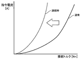
ステップS10では、モータ制御部25において、図7に示すように、指令電流を参照するアシストマップを、指令電流の勾配がより急勾配となる特性を持つアシストマップに切り替え、当該アシストマップを参照してアシスト制御を継続する。
次に、実施形態2の作用効果を説明する。
異常判断部27は、車速信号をさらに考慮してパワーステアリング装置1の異常の有無を判断する。一般的に、高速道路を走行しているときは市街地を走行しているときよりも操舵頻度が低下する。つまり、高速走行時は低速走行時よりも操舵頻度が低下する。操舵頻度が高いほどボールねじ機構4の動作により氷が粉砕されている可能性が高くなる。また、操舵頻度が高いほどインバータ26の発熱量は増大するため、ハウジング5内の水分は凍結していない可能性が高くなる。さらに、高速走行時は低速走行時よりも走行風の影響が大きいため、ハウジング5内の水分が冷えやすくなる。よって、車速信号を考慮することにより、パワーステアリング装置1の異常の有無の判断精度を向上できる。
異常判断部27は、エンジンの駆動状態(エンジン回転数)の信号をさらに考慮してパワーステアリング装置1の異常の有無を判断する。エンジンが停止状態またはエンジン回転数が低い場合、エンジンの発熱量が低いため、エンジン回転数が高い場合よりもハウジング5内の水分が冷えやすくなる。よって、エンジンの駆動状態を考慮することにより、パワーステアリング装置1の異常の有無の判断精度を向上できる。
異常判断部27は、操舵機構2の操舵状態(操舵頻度)をさらに考慮してパワーステアリング装置1の異常の有無を判断する。直近所定時間内の操舵頻度が低いほどハウジング5内の水分が凍結している可能性が高くなる。また、操舵頻度が高いほどボールねじ機構4の動作により氷が粉砕されている可能性が高くなる。さらに、操舵頻度が高いほどインバータ26の発熱量は増大する。よって、操舵機構2の操舵状態を考慮することにより、パワーステアリング装置1の異常の有無の判断精度を向上できる。
異常判断部27は、操舵機構2の操舵トルク信号をさらに考慮してパワーステアリング装置1の異常の有無を判断する。操舵トルクが異常に上昇している場合は、ボールねじ機構4内の水分が凍結したことによりボールねじ機構4に動作不良が生じているおそれがある。よって、操舵トルクを考慮することにより、パワーステアリング装置1の異常の有無の判断精度を向上できる。
異常判断部27は、水分検知素子6における1対の電極間の抵抗値の信号をさらに考慮してパワーステアリング装置1の異常の有無を判断する。1対の電極間の抵抗値は、液体<氷<乾燥(空気)の状態に応じて変化する。よって、抵抗値を考慮することにより、パワーステアリング装置1の異常の有無の判断精度を向上できる。
異常判断部27は、水分検知素子6における1対の電極間の抵抗値の信号の変化履歴に基づき、ハウジング5内の水分の凍結状態を推定する。単に抵抗値が高いだけでは、乾燥状態か凍結状態かを判断することは困難である。しかし、一旦抵抗値が低下し、液体状の水分が有ることを検知した後、抵抗値が所定範囲内で増加した場合、水分が凍結した可能性が高い。よって、抵抗値の変化履歴を考慮することにより、パワーステアリング装置1の異常の有無の判断精度を向上できる。このとき、抵抗値の上昇に合わせて温度情報をさらに考慮することにより、判断精度をさらに向上できる。
異常判断部27は、水分検知素子6における1対の電極間の抵抗値の信号に基づき、水分の純度を推定する。水分の純度によって、温度に対する凍結温度(融点)が異なる。よって、水分の純度を考慮することにより、パワーステアリング装置1の異常の有無の判断精度を向上できる。
モータ制御部25は、異常判断部27が、ハウジング5内の水分が凍結していると判断するとき、指令電流を参照するアシストマップを、指令電流の勾配がより急勾配となる特性を持つアシストマップに切り替える。ボールねじ機構4内の水分が凍結している場合、操舵負荷が増大するため、ドライバの操舵負荷が増大する。そこで、ハウジング5内の水分が凍結した場合には、電動モータ3の出力を増大させることにより、ドライバの操舵負担を軽減でき、利便性を維持できる。
水分検知素子6は、ハウジング5が車両に搭載された状態において、鉛直方向における高さがハウジング5内の最下部に位置するように設置されている。これにより、ハウジング5内に水分が浸入した際、水分の浸入を早期に検知できる。この結果、水分の凍結状態の監視を早期に開始できる。
〔実施形態3〕
次に、実施形態3を説明する。基本的な構成は実施形態1と同じであるため、実施形態1と相違する部分のみ説明する。
実施形態3では、コントロールユニット7による異常判断を、イグニッションスイッチのオフ中も継続する点で実施形態1と相違する。すなわち、イグニッションスイッチがオフの間、水分情報信号受信部24は、水分検知素子6の出力信号を継続して受信し、かつ、温度情報信号受信部23は、温度情報信号を継続して受信し、異常判断部27は、イグニッションスイッチがオフの間の水分検知素子6の出力信号および温度情報の信号に基づき、パワーステアリング装置1の異常の有無を判断する。異常判断部27は、イグニッションスイッチのオフ中に「異常有り」と判断した場合、次回起動時(イグニッションスイッチのオン時)に警告灯を点灯させる。
次に、実施形態3の作用効果を説明する。
イグニッションスイッチがオンされたときの温度が凍結温度よりも高い場合であっても、ハウジング5内の水分が凍結している可能性がある。また、イグニッションスイッチがオフされた時点では水分が検知されていなくても、その後、イグニッションスイッチのオフ中に水分が浸入する可能性がある。よって、イグニッションスイッチがオフの間の水分の検知情報と温度情報とに基づき、水分の有無および凍結の可能性を考慮することにより、さらに安全性を向上できる。
〔実施形態4〕
次に、実施形態4を説明する。基本的な構成は実施形態1と同じであるため、実施形態1と相違する部分のみ説明する。
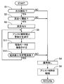
図8は、実施形態4のコントロールユニット7による異常判断処理の流れを示すフローチャートである。図4に示した実施形態1の異常判断処理と異なるステップのみ説明する。
ステップS11では、モータ制御部25において、電動モータ3を振動させる指令信号を出力する。
ステップS12では、異常判断部27において、電動モータ3の電流値が所定電流値以上であるかを判定する。YESの場合はステップS5へ戻り、NOの場合はステップS4へ進む。
次に、実施形態4の作用効果を説明する。
モータ制御部25は、異常判断部27がハウジング5内に水分の浸入有り、かつ温度情報の信号が凍結判断閾値よりも低いと判断するとき、電動モータ3を振動させる指令信号を出力する。電動モータ3を振動させてナット13を左右に動かすことにより、凍結が始まった水分の凝固を遅延できる。
異常判断部27は、モータ制御部25が電動モータ3を振動させる指令信号を出力している間、電動モータ3の電流値の信号に基づき、ハウジング5内の水分の凍結状態を判断する。ハウジング5内の水分が凍結している場合、電動モータ3の負荷が上昇するため、これに伴い電流値を上昇するため、電流値を見ることで異常判断精度を向上できる。
〔実施形態5〕
次に、実施形態5を説明する。基本的な構成は実施形態1と同じであるため、実施形態1と相違する部分のみ説明する。
実施形態5の温度センサ33は、ボールねじ機構収容部19内に設置されている。コントロールユニット7の温度情報信号受信部23は、CAN通信経由で温度センサ33からの温度情報の信号を受信する。車両側に設置された温度センサ33の情報を使用することにより、よりボールねじ機構4側の温度に近い温度を取得できる。これにより、パワーステアリング装置1の異常判断精度を向上できる。
次に、実施形態5を説明する。基本的な構成は実施形態1と同じであるため、実施形態1と相違する部分のみ説明する。
実施形態5の温度センサ33は、ボールねじ機構収容部19内に設置されている。コントロールユニット7の温度情報信号受信部23は、CAN通信経由で温度センサ33からの温度情報の信号を受信する。車両側に設置された温度センサ33の情報を使用することにより、よりボールねじ機構4側の温度に近い温度を取得できる。これにより、パワーステアリング装置1の異常判断精度を向上できる。
〔他の実施形態〕
以上、本発明を実施するための実施形態を説明したが、本発明の具体的な構成は実施形態の構成に限定されるものではなく、発明の要旨を逸脱しない範囲の設計変更等があっても本発明に含まれる。また、上述した課題の少なくとも一部を解決できる範囲、または、効果の少なくとも一部を奏する範囲において、特許請求の範囲および明細書に記載された各構成要素の任意の組み合わせ、または、省略が可能である。
水分検知素子を電動モータ収容部内に設置してもよい。
伝達機構はボールねじ機構に限らない。
本発明は、電気自動車やハイブリッド車などの電動車両のパワーステアリング装置にも適用できる。特に内燃機関を持たない電気自動車では、内燃機関の余熱でハウジング内の温度を高められない。よって、外気温が低いとハウジング内の水分が凍結しやすいため、本発明の適用による効果は顕著である。電動車両の場合、車両の起動スイッチは、スタートスイッチやスタンバイスイッチ等である。
電動モータを振動させている間、電動モータの振動周波数の信号に基づき、ハウジング内の水分の凍結状態を判断してもよい。水分が凍結している場合、電動モータの動作に対する抵抗が大きくなるため、指令電流の振動周波数に対し電動モータの振動周波数は低くなる。
エンジンの駆動状態は、エンジン回転数に限らず、アイドリングストップ中か否かでもよい。電動車両の場合は、動力源の駆動状態としてモータやインバータの状態を監視すればよい。
操舵機構の操舵状態は、操舵頻度に限らず、操舵角、操舵速度、操舵累積時間等でもよい。
操舵負荷は、操舵トルクに限らず、電動モータの電流値信号でもよい。
以上説明した実施形態から把握し得る他の態様について、以下に記載する。
パワーステアリング装置は、その一つの態様において、転舵輪を転舵させる操舵機構と;前記操舵機構に操舵力を付与する電動モータと;前記操舵機構と前記電動モータの間に設けられ、前記電動モータの回転力を前記操舵機構に伝達する伝達機構と;前記操舵機構の少なくとも一部と、前記伝達機構と、前記電動モータと、を収容するハウジングと;前記ハウジング内に設けられ、水分を検知する水分検知素子と;マイクロコンピュータが搭載された制御装置とを備える。前記制御装置は、前記電動モータを駆動制御するための指令電流を出力するモータ制御部と;温度情報を表す信号を受信する温度情報信号受信部と;前記水分検知素子の出力信号を受信する水分情報信号受信部と;前記温度情報を表す信号と、前記水分検知素子の前記出力信号と、に基づいて、前記パワーステアリング装置の異常の有無を判断する異常判断部とを備える。
より好ましい態様では、上記態様において、前記制御装置は、車両の運転状態を表す信号を受信する運転状態信号受信部を備え、前記異常判断部は、前記温度情報を表す信号と、前記水分検知素子の前記出力信号と、前記車両の運転状態を表す信号と、に基づいて、前記パワーステアリング装置の異常の有無を判断する。
別の好ましい態様では、上記態様のいずれかにおいて、前記異常判断部は、前記温度情報を表す信号と、前記水分検知素子の前記出力信号と、前記車両の前記運転状態を表す信号と、車速信号と、に基づいて、前記パワーステアリング装置の異常の有無を判断する。
さらに別の好ましい態様では、上記態様のいずれかにおいて、前記異常判断部は、前記温度情報を表す信号と、前記水分検知素子の前記出力信号と、前記車両の前記運転状態を表す信号と、前記車両の動力源の駆動状態を表す信号と、に基づいて、前記パワーステアリング装置の異常の有無を判断する。
さらに別の好ましい態様では、上記態様のいずれかにおいて、前記異常判断部は、前記温度情報を表す信号と、前記水分検知素子の前記出力信号と、前記車両の前記運転状態を表す信号と、前記操舵機構の操舵状態を表す信号と、に基づいて、前記パワーステアリング装置の異常の有無を判断する。
さらに別の好ましい態様では、上記態様のいずれかにおいて、前記異常判断部は、前記温度情報を表す信号と、前記水分検知素子の前記出力信号と、前記車両の前記運転状態を表す信号と、前記操舵機構の操舵トルク信号または前記電動モータの電流値信号と、に基づいて、前記パワーステアリング装置の異常の有無を判断する。
さらに別の好ましい態様では、上記態様のいずれかにおいて、前記水分検知素子は、1対の電極を備え、前記異常判断部は、前記温度情報を表す信号と、前記水分検知素子の前記出力信号と、前記1対の電極間の抵抗値を表す信号と、に基づいて、前記パワーステアリング装置の異常の有無を判断する。
さらに別の好ましい態様では、上記態様のいずれかにおいて、前記異常判断部は、前記1対の電極間の前記抵抗値を表す前記信号の変化履歴に基づき、前記ハウジング内の水分の凍結状態を推定する。
さらに別の好ましい態様では、上記態様のいずれかにおいて、前記異常判断部は、前記1対の電極間の前記抵抗値を表す信号に基づき、水分の純度を推定する。
さらに別の好ましい態様では、上記態様のいずれかにおいて、車両の起動スイッチがオフの間、前記水分情報信号受信部は、前記水分検知素子の前記出力信号を継続して受信し、かつ、前記温度情報信号受信部は、前記温度情報を表す前記信号を継続して受信し、
前記異常判断部は、前記車両の前記起動スイッチがオフの間の前記水分検知素子の前記出力信号および前記温度情報を表す前記信号に基づき、前記パワーステアリング装置の異常の有無を判断する。
さらに別の好ましい態様では、上記態様のいずれかにおいて、前記制御装置は、前記操舵機構の操舵トルク信号を受信する操舵トルク信号受信部を備え、前記モータ制御部は、前記操舵トルク信号に対する前記指令電流についての複数種類のマップを備え、前記異常判断部が、前記ハウジング内の水分が凍結していると判断するとき、前記モータ制御部は、使用すべきマップを前記複数種類のマップの間で切り替える。
さらに別の好ましい態様では、上記態様のいずれかにおいて、前記異常判断部が、前記ハウジング内への水分の浸入が有り、かつ、前記温度情報を表す前記信号が所定値以下の温度を表していると判断するとき、前記モータ制御部は、前記電動モータを振動させるための指令信号を出力する。
さらに別の好ましい態様では、上記態様のいずれかにおいて、前記異常判断部は、前記モータ制御部が前記電動モータを振動させるための指令信号を出力している間の、前記電動モータの電流値を表す信号、または、前記電動モータの振動周波数を表す信号に基づき、前記ハウジング内の水分の凍結状態を判断する。
さらに別の好ましい態様では、上記態様のいずれかにおいて、前記異常判断部は、前記温度情報を表す信号と、前記水分検知素子の前記出力信号と、前記温度情報を表す前記信号の変化に対する遅れ要素と、に基づいて、前記ハウジング内の水分の凍結状態を判断する。
さらに別の好ましい態様では、上記態様のいずれかにおいて、前記温度情報を取得する温度センサを備え、前記ハウジングは、前記制御装置を収容する制御装置収容部を備え、前記温度センサは、前記制御装置収容部内に設けられる。
さらに別の好ましい態様では、上記態様のいずれかにおいて、前記異常判断部は、前記制御装置収容部内の温度変化に応じて前記温度情報を表す前記信号を補正する。
さらに別の好ましい態様では、上記態様のいずれかにおいて、前記温度情報信号受信部は、車両に設けられた温度センサの信号をCAN通信経由で受信する。
さらに別の好ましい態様では、上記態様のいずれかにおいて、前記水分検知素子は、前記ハウジングが車両に搭載された状態において、鉛直方向において前記伝達機構とオーバーラップする位置に設けられる。
さらに別の好ましい態様では、上記態様のいずれかにおいて、前記ハウジングは、前記伝達機構を収容する伝達機構収容部と、前記電動モータを収容する電動モータ収容部と、を備え、前記水分検知素子は、前記伝達機構収容部または前記電動モータ収容部内に設けられる。
さらに別の好ましい態様では、上記態様のいずれかにおいて、前記水分検知素子は、前記ハウジングが車両に搭載された状態において、前記ハウジング内の最下部に位置するように設けられる。
本願は、2016年12月13日出願の日本特許出願番号2016-240913号に基づく優先権を主張する。2016年12月13日出願の日本特許出願番号2016-240913号の明細書、特許請求の範囲、図面及び要約書を含む全ての開示内容は、参照により全体として本願に組み込まれる。
1 パワーステアリング装置、2 操舵機構、3 電動モータ、4 ボールねじ機構(伝達機構)、5 ハウジング、6 水分検知素子、7 コントロールユニット(制御装置)、18 モータ収容部(制御装置収容部、電動モータ収容部)、19 ボールねじ機構収容部(伝達機構収容部)、21 操舵トルク信号受信部、22 運転状態信号受信部、23 温度情報信号受信部、24 水分情報信号受信部、25 モータ制御部、27 異常判断部、33 温度センサ
Claims (20)
- パワーステアリング装置であって、
転舵輪を転舵させる操舵機構と、
前記操舵機構に操舵力を付与する電動モータと、
前記操舵機構と前記電動モータの間に設けられ、前記電動モータの回転力を前記操舵機構に伝達する伝達機構と、
前記操舵機構の少なくとも一部と、前記伝達機構と、前記電動モータと、を収容するハウジングと、
前記ハウジング内に設けられ、水分を検知する水分検知素子と、
マイクロコンピュータが搭載された制御装置と、
を備え、
前記制御装置は、
前記電動モータを駆動制御するための指令電流を出力するモータ制御部と、
温度情報を表す信号を受信する温度情報信号受信部と、
前記水分検知素子の出力信号を受信する水分情報信号受信部と、
前記温度情報を表す信号と、前記水分検知素子の前記出力信号と、に基づいて、前記パワーステアリング装置の異常の有無を判断する異常判断部と、
を備える
パワーステアリング装置。 - 請求項1に記載のパワーステアリング装置において、
前記制御装置は、車両の運転状態を表す信号を受信する運転状態信号受信部を備え、
前記異常判断部は、前記温度情報を表す信号と、前記水分検知素子の前記出力信号と、前記車両の運転状態を表す信号と、に基づいて、前記パワーステアリング装置の異常の有無を判断する
パワーステアリング装置。 - 請求項2に記載のパワーステアリング装置において、
前記異常判断部は、前記温度情報を表す信号と、前記水分検知素子の前記出力信号と、前記車両の前記運転状態を表す信号と、車速信号と、に基づいて、前記パワーステアリング装置の異常の有無を判断する
パワーステアリング装置。 - 請求項2に記載のパワーステアリング装置において、
前記異常判断部は、前記温度情報を表す信号と、前記水分検知素子の前記出力信号と、前記車両の前記運転状態を表す信号と、前記車両の動力源の駆動状態を表す信号と、に基づいて、前記パワーステアリング装置の異常の有無を判断する
パワーステアリング装置。 - 請求項2に記載のパワーステアリング装置において、
前記異常判断部は、前記温度情報を表す信号と、前記水分検知素子の前記出力信号と、前記車両の前記運転状態を表す信号と、前記操舵機構の操舵状態を表す信号と、に基づいて、前記パワーステアリング装置の異常の有無を判断する
パワーステアリング装置。 - 請求項2に記載のパワーステアリング装置において、
前記異常判断部は、前記温度情報を表す信号と、前記水分検知素子の前記出力信号と、前記車両の前記運転状態を表す信号と、前記操舵機構の操舵トルク信号または前記電動モータの電流値信号と、に基づいて、前記パワーステアリング装置の異常の有無を判断する
パワーステアリング装置。 - 請求項1に記載のパワーステアリング装置において、
前記水分検知素子は、1対の電極を備え、
前記異常判断部は、前記温度情報を表す信号と、前記水分検知素子の前記出力信号と、前記1対の電極間の抵抗値を表す信号と、に基づいて、前記パワーステアリング装置の異常の有無を判断する
パワーステアリング装置。 - 請求項7に記載のパワーステアリング装置において、
前記異常判断部は、前記1対の電極間の前記抵抗値を表す前記信号の変化履歴に基づき、前記ハウジング内の水分の凍結状態を推定する
パワーステアリング装置。 - 請求項7に記載のパワーステアリング装置において、
前記異常判断部は、前記1対の電極間の前記抵抗値を表す前記信号に基づき、水分の純度を推定する
パワーステアリング装置。 - 請求項1に記載のパワーステアリング装置において、
車両の起動スイッチがオフの間、前記水分情報信号受信部は、前記水分検知素子の前記出力信号を継続して受信し、かつ、前記温度情報信号受信部は、前記温度情報を表す前記信号を継続して受信し、
前記異常判断部は、前記車両の前記起動スイッチがオフの間の前記水分検知素子の前記出力信号および前記温度情報を表す前記信号に基づき、前記パワーステアリング装置の異常の有無を判断する
パワーステアリング装置。 - 請求項1に記載のパワーステアリング装置において、
前記制御装置は、前記操舵機構の操舵トルク信号を受信する操舵トルク信号受信部を備え、
前記モータ制御部は、前記操舵トルク信号に対する前記指令電流についての複数種類のマップを備え、
前記異常判断部が、前記ハウジング内の水分が凍結していると判断するとき、前記モータ制御部は、使用すべきマップを前記複数種類のマップの間で切り替える
パワーステアリング装置。 - 請求項1に記載のパワーステアリング装置において、
前記異常判断部が、前記ハウジング内への水分の浸入が有り、かつ、前記温度情報を表す前記信号が所定値以下の温度を表していると判断するとき、前記モータ制御部は、前記電動モータを振動させるための指令信号を出力する
パワーステアリング装置。 - 請求項12に記載のパワーステアリング装置において、
前記異常判断部は、前記モータ制御部が前記電動モータを振動させるための指令信号を出力している間の、前記電動モータの電流値を表す信号、または、前記電動モータの振動周波数を表す信号に基づき、前記ハウジング内の水分の凍結状態を判断する
パワーステアリング装置。 - 請求項1に記載のパワーステアリング装置において、
前記異常判断部は、前記温度情報を表す信号と、前記水分検知素子の前記出力信号と、前記温度情報を表す前記信号の変化に対する遅れ要素と、に基づいて、前記ハウジング内の水分の凍結状態を判断する
パワーステアリング装置。 - 請求項1に記載のパワーステアリング装置において、
前記温度情報を取得する温度センサを備え、
前記ハウジングは、前記制御装置を収容する制御装置収容部を備え、
前記温度センサは、前記制御装置収容部内に設けられる
パワーステアリング装置。 - 請求項15に記載のパワーステアリング装置において、
前記異常判断部は、前記制御装置収容部内の温度変化に応じて前記温度情報を表す前記信号を補正する
パワーステアリング装置。 - 請求項1に記載のパワーステアリング装置において、
前記温度情報信号受信部は、車両に設けられた温度センサからの信号をCAN通信経由で受信する
パワーステアリング装置。 - 請求項1に記載のパワーステアリング装置において、
前記水分検知素子は、前記ハウジングが車両に搭載された状態において、鉛直方向において前記伝達機構とオーバーラップする位置に設けられる
パワーステアリング装置。 - 請求項1に記載のパワーステアリング装置において、
前記ハウジングは、前記伝達機構を収容する伝達機構収容部と、前記電動モータを収容する電動モータ収容部と、を備え、
前記水分検知素子は、前記伝達機構収容部または前記電動モータ収容部内に設けられる
パワーステアリング装置。 - 請求項1に記載のパワーステアリング装置において、
前記水分検知素子は、前記ハウジングが車両に搭載された状態において、前記ハウジング内の最下部に位置するように設けられる
パワーステアリング装置。
Applications Claiming Priority (2)
| Application Number | Priority Date | Filing Date | Title |
|---|---|---|---|
| JP2016-240913 | 2016-12-13 | ||
| JP2016240913A JP2018095059A (ja) | 2016-12-13 | 2016-12-13 | パワーステアリング装置 |
Publications (1)
| Publication Number | Publication Date |
|---|---|
| WO2018110216A1 true WO2018110216A1 (ja) | 2018-06-21 |
Family
ID=62558350
Family Applications (1)
| Application Number | Title | Priority Date | Filing Date |
|---|---|---|---|
| PCT/JP2017/041797 Ceased WO2018110216A1 (ja) | 2016-12-13 | 2017-11-21 | パワーステアリング装置 |
Country Status (2)
| Country | Link |
|---|---|
| JP (1) | JP2018095059A (ja) |
| WO (1) | WO2018110216A1 (ja) |
Cited By (7)
| Publication number | Priority date | Publication date | Assignee | Title |
|---|---|---|---|---|
| US20190277721A1 (en) * | 2018-03-07 | 2019-09-12 | Steering Solutions Ip Holding Corporation | Water intrusion detection |
| CN110871836A (zh) * | 2018-09-04 | 2020-03-10 | 日立汽车系统株式会社 | 转向装置 |
| CN115626214A (zh) * | 2021-07-02 | 2023-01-20 | 汉拿万都株式会社 | 检测车轮致动器的气密性的转向装置 |
| US20250083739A1 (en) * | 2023-09-12 | 2025-03-13 | Robert Bosch Gmbh | Apparatus and Method for Detecting Damage to a Steering System |
| US20260139712A1 (en) * | 2021-10-28 | 2026-05-21 | Trelleborg Carquefou | Steering bellows |
| WO2026126371A1 (ja) * | 2024-12-11 | 2026-06-18 | 株式会社ジェイテクト | 操舵制御装置、および操舵制御方法 |
| US12679448B2 (en) * | 2022-10-18 | 2026-07-14 | Hl Mando Corporation | Steering control device and method |
Families Citing this family (6)
| Publication number | Priority date | Publication date | Assignee | Title |
|---|---|---|---|---|
| KR102910609B1 (ko) * | 2021-07-12 | 2026-01-12 | 에이치엘만도 주식회사 | 부츠 손상 감지 장치 및 방법 |
| WO2025257893A1 (ja) * | 2024-06-10 | 2025-12-18 | Astemo株式会社 | ステアリング装置、判定方法、制御装置、プログラム |
| WO2026126372A1 (ja) * | 2024-12-11 | 2026-06-18 | 株式会社ジェイテクト | 操舵制御装置、および操舵制御方法 |
| WO2026126370A1 (ja) * | 2024-12-11 | 2026-06-18 | 株式会社ジェイテクト | 操舵制御装置、および操舵制御方法 |
| WO2026126373A1 (ja) * | 2024-12-11 | 2026-06-18 | 株式会社ジェイテクト | 操舵制御装置、および操舵制御方法 |
| WO2026126374A1 (ja) * | 2024-12-11 | 2026-06-18 | 株式会社ジェイテクト | 操舵制御装置、および操舵制御方法 |
Citations (6)
| Publication number | Priority date | Publication date | Assignee | Title |
|---|---|---|---|---|
| JPS63274838A (ja) * | 1987-05-05 | 1988-11-11 | Tadayuki Yamada | 路面凍結検知器 |
| JPH02254349A (ja) * | 1989-03-28 | 1990-10-15 | Sumitomo Metal Ind Ltd | 路面の凍結検知方法及び装置 |
| JP2013510034A (ja) * | 2009-11-04 | 2013-03-21 | ツェットエフ、レンクジステメ、ゲゼルシャフト、ミット、ベシュレンクテル、ハフツング | パワーステアリングシステムの操作のための方法 |
| JP2013101050A (ja) * | 2011-11-08 | 2013-05-23 | Fujitsu Ltd | 雪密度センサ |
| JP2013237401A (ja) * | 2012-05-16 | 2013-11-28 | Jtekt Corp | ステアリング装置 |
| WO2016098557A1 (ja) * | 2014-12-16 | 2016-06-23 | 日立オートモティブシステムズ株式会社 | 水分検知システムおよび電動パワーステアリング装置 |
-
2016
- 2016-12-13 JP JP2016240913A patent/JP2018095059A/ja active Pending
-
2017
- 2017-11-21 WO PCT/JP2017/041797 patent/WO2018110216A1/ja not_active Ceased
Patent Citations (6)
| Publication number | Priority date | Publication date | Assignee | Title |
|---|---|---|---|---|
| JPS63274838A (ja) * | 1987-05-05 | 1988-11-11 | Tadayuki Yamada | 路面凍結検知器 |
| JPH02254349A (ja) * | 1989-03-28 | 1990-10-15 | Sumitomo Metal Ind Ltd | 路面の凍結検知方法及び装置 |
| JP2013510034A (ja) * | 2009-11-04 | 2013-03-21 | ツェットエフ、レンクジステメ、ゲゼルシャフト、ミット、ベシュレンクテル、ハフツング | パワーステアリングシステムの操作のための方法 |
| JP2013101050A (ja) * | 2011-11-08 | 2013-05-23 | Fujitsu Ltd | 雪密度センサ |
| JP2013237401A (ja) * | 2012-05-16 | 2013-11-28 | Jtekt Corp | ステアリング装置 |
| WO2016098557A1 (ja) * | 2014-12-16 | 2016-06-23 | 日立オートモティブシステムズ株式会社 | 水分検知システムおよび電動パワーステアリング装置 |
Cited By (8)
| Publication number | Priority date | Publication date | Assignee | Title |
|---|---|---|---|---|
| US20190277721A1 (en) * | 2018-03-07 | 2019-09-12 | Steering Solutions Ip Holding Corporation | Water intrusion detection |
| US11137314B2 (en) * | 2018-03-07 | 2021-10-05 | Steering Solutions Ip Holding Corporation | Water intrusion detection |
| CN110871836A (zh) * | 2018-09-04 | 2020-03-10 | 日立汽车系统株式会社 | 转向装置 |
| CN115626214A (zh) * | 2021-07-02 | 2023-01-20 | 汉拿万都株式会社 | 检测车轮致动器的气密性的转向装置 |
| US20260139712A1 (en) * | 2021-10-28 | 2026-05-21 | Trelleborg Carquefou | Steering bellows |
| US12679448B2 (en) * | 2022-10-18 | 2026-07-14 | Hl Mando Corporation | Steering control device and method |
| US20250083739A1 (en) * | 2023-09-12 | 2025-03-13 | Robert Bosch Gmbh | Apparatus and Method for Detecting Damage to a Steering System |
| WO2026126371A1 (ja) * | 2024-12-11 | 2026-06-18 | 株式会社ジェイテクト | 操舵制御装置、および操舵制御方法 |
Also Published As
| Publication number | Publication date |
|---|---|
| JP2018095059A (ja) | 2018-06-21 |
Similar Documents
| Publication | Publication Date | Title |
|---|---|---|
| JP2018095059A (ja) | パワーステアリング装置 | |
| US20180194390A1 (en) | Power steering device and device for controlling power steering device | |
| KR101991210B1 (ko) | 파워 스티어링 장치, 및 파워 스티어링 장치의 제어 장치 | |
| US10392048B2 (en) | Power steering device and control device therefor | |
| US10994773B2 (en) | Steering system | |
| JP4379412B2 (ja) | パワーステアリング用電源制御装置 | |
| CN101326093B (zh) | 电动转向设备及其控制方法 | |
| JP6375545B2 (ja) | パワーステアリング装置およびパワーステアリング装置の制御回路 | |
| JP6343829B2 (ja) | 水分検知システムおよび電動パワーステアリング装置 | |
| EP2913247A2 (en) | Vehicle steering device, failure determination method for vehicle steering device, and control method for steering motor | |
| US20120290175A1 (en) | Control device of electrohydraulic power steering apparatus | |
| US9174668B2 (en) | Electric power steering system | |
| US20070193818A1 (en) | Vehicle steering system | |
| US9061699B2 (en) | Vehicle steering system | |
| CN106985900B (zh) | 用于控制电机驱动动力转向系统的方法和设备 | |
| JP2015110380A (ja) | 駐車支援装置 | |
| US20180057009A1 (en) | Vehicle Controller | |
| US20130197787A1 (en) | Engine restart control device | |
| CN114604312A (zh) | 电动转向装置 | |
| JP3912217B2 (ja) | 電動操舵装置 | |
| KR20180053789A (ko) | 전류센서 옵셋 보상 방법 | |
| JP6032058B2 (ja) | 電動パワーステアリング装置 | |
| JP2004064921A (ja) | 電動パワーステアリング装置 | |
| JP2005088861A (ja) | パワーステアリング装置 | |
| JP5370729B2 (ja) | パワーステアリング装置 |
Legal Events
| Date | Code | Title | Description |
|---|---|---|---|
| 121 | Ep: the epo has been informed by wipo that ep was designated in this application |
Ref document number: 17881474 Country of ref document: EP Kind code of ref document: A1 |
|
| NENP | Non-entry into the national phase |
Ref country code: DE |
|
| 122 | Ep: pct application non-entry in european phase |
Ref document number: 17881474 Country of ref document: EP Kind code of ref document: A1 |