WO2018110022A1 - 画像投影システム、画像投影装置、及び画像投影方法 - Google Patents
画像投影システム、画像投影装置、及び画像投影方法 Download PDFInfo
- Publication number
- WO2018110022A1 WO2018110022A1 PCT/JP2017/034231 JP2017034231W WO2018110022A1 WO 2018110022 A1 WO2018110022 A1 WO 2018110022A1 JP 2017034231 W JP2017034231 W JP 2017034231W WO 2018110022 A1 WO2018110022 A1 WO 2018110022A1
- Authority
- WO
- WIPO (PCT)
- Prior art keywords
- image
- person
- projection
- imaging device
- information
- Prior art date
Links
Images


Classifications
-
- H—ELECTRICITY
- H04—ELECTRIC COMMUNICATION TECHNIQUE
- H04N—PICTORIAL COMMUNICATION, e.g. TELEVISION
- H04N9/00—Details of colour television systems
- H04N9/12—Picture reproducers
- H04N9/31—Projection devices for colour picture display, e.g. using electronic spatial light modulators [ESLM]
- H04N9/3179—Video signal processing therefor
- H04N9/3185—Geometric adjustment, e.g. keystone or convergence
-
- G—PHYSICS
- G03—PHOTOGRAPHY; CINEMATOGRAPHY; ANALOGOUS TECHNIQUES USING WAVES OTHER THAN OPTICAL WAVES; ELECTROGRAPHY; HOLOGRAPHY
- G03B—APPARATUS OR ARRANGEMENTS FOR TAKING PHOTOGRAPHS OR FOR PROJECTING OR VIEWING THEM; APPARATUS OR ARRANGEMENTS EMPLOYING ANALOGOUS TECHNIQUES USING WAVES OTHER THAN OPTICAL WAVES; ACCESSORIES THEREFOR
- G03B21/00—Projectors or projection-type viewers; Accessories therefor
- G03B21/14—Details
-
- G—PHYSICS
- G06—COMPUTING; CALCULATING OR COUNTING
- G06V—IMAGE OR VIDEO RECOGNITION OR UNDERSTANDING
- G06V10/00—Arrangements for image or video recognition or understanding
- G06V10/10—Image acquisition
- G06V10/12—Details of acquisition arrangements; Constructional details thereof
- G06V10/14—Optical characteristics of the device performing the acquisition or on the illumination arrangements
- G06V10/145—Illumination specially adapted for pattern recognition, e.g. using gratings
-
- G—PHYSICS
- G06—COMPUTING; CALCULATING OR COUNTING
- G06V—IMAGE OR VIDEO RECOGNITION OR UNDERSTANDING
- G06V40/00—Recognition of biometric, human-related or animal-related patterns in image or video data
- G06V40/10—Human or animal bodies, e.g. vehicle occupants or pedestrians; Body parts, e.g. hands
- G06V40/16—Human faces, e.g. facial parts, sketches or expressions
- G06V40/161—Detection; Localisation; Normalisation
- G06V40/166—Detection; Localisation; Normalisation using acquisition arrangements
-
- G—PHYSICS
- G09—EDUCATION; CRYPTOGRAPHY; DISPLAY; ADVERTISING; SEALS
- G09G—ARRANGEMENTS OR CIRCUITS FOR CONTROL OF INDICATING DEVICES USING STATIC MEANS TO PRESENT VARIABLE INFORMATION
- G09G5/00—Control arrangements or circuits for visual indicators common to cathode-ray tube indicators and other visual indicators
- G09G5/36—Control arrangements or circuits for visual indicators common to cathode-ray tube indicators and other visual indicators characterised by the display of a graphic pattern, e.g. using an all-points-addressable [APA] memory
- G09G5/38—Control arrangements or circuits for visual indicators common to cathode-ray tube indicators and other visual indicators characterised by the display of a graphic pattern, e.g. using an all-points-addressable [APA] memory with means for controlling the display position
-
- H—ELECTRICITY
- H04—ELECTRIC COMMUNICATION TECHNIQUE
- H04N—PICTORIAL COMMUNICATION, e.g. TELEVISION
- H04N5/00—Details of television systems
- H04N5/72—Modifying the appearance of television pictures by optical filters or diffusing screens
-
- H—ELECTRICITY
- H04—ELECTRIC COMMUNICATION TECHNIQUE
- H04N—PICTORIAL COMMUNICATION, e.g. TELEVISION
- H04N5/00—Details of television systems
- H04N5/74—Projection arrangements for image reproduction, e.g. using eidophor
-
- H—ELECTRICITY
- H04—ELECTRIC COMMUNICATION TECHNIQUE
- H04N—PICTORIAL COMMUNICATION, e.g. TELEVISION
- H04N9/00—Details of colour television systems
- H04N9/12—Picture reproducers
- H04N9/31—Projection devices for colour picture display, e.g. using electronic spatial light modulators [ESLM]
- H04N9/3191—Testing thereof
- H04N9/3194—Testing thereof including sensor feedback
Definitions
- the present disclosure relates to an image projection system, an image projection apparatus, and an image projection method.
- the anti-voyeurism device described in Patent Document 1 includes a light source device, a projection lens system, and control means.
- the light source device is composed of infrared light and generates interference light that degrades video content.
- the lens system projects the interference light emitted from the light source device toward the screen.
- the control means drives and controls the light source device so as to generate disturbing light at a predetermined cycle time interval or at irregular time intervals.
- the anti-peeping device projects the interference light generated intermittently over time on the video content projected on the screen.
- the interference light may be superimposed on the entire subject including the person, resulting in a state where the person cannot be grasped at all.
- This disclosure is intended to reduce visibility by limiting to a part of an image area in a captured image.
- the image projection system of the present disclosure includes an image projection device that projects an image using invisible light, an imaging device, and an arithmetic device.
- the arithmetic device based on the positional relationship between the predetermined pattern image projected by the image projection device and the predetermined pattern image captured by the imaging device, the camera coordinates used by the imaging device and the projector coordinates used by the image projection device. Conversion information for converting between and is generated.
- the imaging device images a subject including a person.
- the arithmetic unit detects a first position indicating a position related to the camera coordinates of the human face area. Based on the conversion information, the arithmetic device converts the information on the first position into information on the second position indicating the position related to the projector coordinates of the face area.
- the image projecting device projects the warning image on the entire face area based on the information on the second position.
- An image projection apparatus includes a projection unit that projects an image using infrared rays, an acquisition unit that acquires an image captured by an imaging device, a predetermined pattern image projected by the projection unit, and an imaging device. And a processing unit that generates conversion information for converting the camera coordinates used by the imaging apparatus and the projector coordinates used by the image projection apparatus based on the positional relationship with the predetermined pattern image.
- the processing unit detects a first position indicating a position related to the camera coordinates of the face area of the person included in the subject imaged by the imaging device, and converts the information on the first position based on the conversion information to the face area. Is converted into second position information indicating the position related to the projector coordinates.
- the projection unit projects a warning image based on the information on the second position.
- An image projecting method of the present disclosure is an image projecting method in an image projecting system, which projects a first pattern image projected by an image projecting device, captures a first pattern image by an image capturing device, and performs second imaging.
- a pattern image is acquired, and conversion information for converting camera coordinates used by the imaging device and projector coordinates used by the image projection device is generated based on the positional relationship between the first pattern image and the second pattern image.
- the imaging device captures a subject including a person, detects a first position indicating the position of the person's face area related to the camera coordinates, and based on the conversion information, the first position information is used as a projector for the face area. It converts into the information of the 2nd position which shows the position which concerns on a coordinate, and a warning image is projected on the whole area
- visibility can be reduced by limiting to a partial image area of the captured image.
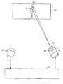
- FIG. 1 is a configuration diagram illustrating an example of an image projection system according to the first embodiment.
- FIG. 2 is an explanatory diagram showing an outline of the operation of the image projection system.
- FIG. 3 is an explanatory diagram showing an example of a projection pattern image.
- FIG. 4 is a block diagram illustrating a functional configuration example of the arithmetic device according to the first embodiment.
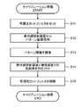
- FIG. 5 is a flowchart illustrating an example of the calibration process of the image projection system.
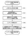
- FIG. 6 is a flowchart illustrating an example of a content image (warning image) projection process in consideration of a human face area.
- FIG. 7 is a schematic diagram for explaining use case 1.
- FIG. 8 is a schematic diagram for explaining use case 2.
- FIG. 9 is a schematic diagram for explaining use case 3.
- FIG. 10 is a block diagram illustrating a functional configuration example of the arithmetic device according to the second embodiment.
- FIG. 11 is a flowchart illustrating an example of a content image (decoration image) projection process in consideration of a human face area.
- FIG. 12 is a schematic diagram for explaining use case 4.
- FIG. 13 is a schematic diagram for explaining use case 5.
- FIG. 14 is a schematic diagram for explaining the use case 6.
- FIG. 15 is a configuration diagram illustrating an example of an image projection system according to the third embodiment.
- FIG. 16 is a block diagram illustrating a functional configuration example of the processor of the infrared projector.
- FIG. 17 is a schematic diagram illustrating a first projection example of a content image when there are a plurality of persons.
- FIG. 18 is a schematic diagram illustrating a second projection example of a content image when there are a plurality of persons.
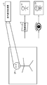
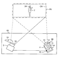
- FIG. 1 is a configuration diagram illustrating an example of an image projection system 1 according to the first embodiment.
- the image projection system 1 performs projection mapping for projecting an image constituting desired video content onto a projection target.
- the image projection system 1 can project a moving image onto a projection target (for example, a person 2).
- the person 2 is, for example, a dancer or an athlete.
- the person 2 may be a changing person (animal body) or a person (stationary object) that does not change.
- the image projection system 1 includes an infrared projection device 3, an imaging device 5, and a calculation device 6.
- the infrared projector 3 projects an infrared image toward a projection target including the person 2.
- the imaging device 5 captures an infrared image and a visible light image projected on an imaging target including the person 2.
- the arithmetic device 6 is communicably connected to the infrared projection device 3 and the imaging device 5 and executes various processes related to projection mapping.
- the infrared projector 3 and the imaging device 5 can be arranged at predetermined positions, respectively.
- the infrared projector 3 captures an image with respect to a predetermined spatial projection range PA.
- the projection range PA is fixed.
- the imaging device 5 images a subject included in a predetermined spatial imaging range CA.
- the imaging range CA is fixed.
- the projection range PA includes an imaging range CA.
- the infrared projector 3 includes an emission unit 10, an infrared light source (IR light source) 11, a DMD (Digital Mirror Device) 12, a control board, a processor, and a memory.
- the memory stores a program that causes the processor to execute various operation instructions in the infrared projector 3.
- the emitting unit 10 includes a lens system such as a projection lens.
- the infrared light source 11 includes an infrared LED (Light Emitting Diode) that emits light in the infrared region.
- the DMD 12 forms a desired infrared image including a moving image or a still image by selectively reflecting the light from the infrared light source 11 toward the projection lens.
- the DMD 12 is digitally controllable compared to a liquid crystal type projection. Therefore, the DMD 12 has a high affinity with a digital signal that can adjust light with high accuracy.
- the control board and the processor control operations of the infrared light source 11 and the DMD 12.
- the infrared light source 11 other light sources such as a laser can be adopted as long as a desired luminance can be achieved.
- the infrared projector 3 is an example of an image projector using invisible light.
- the invisible light image projection apparatus may project an invisible light image using other light such as ultraviolet rays as well as infrared rays.
- the invisible light is, for example, invisible light that is not visually recognized by humans or light equivalent thereto, and does not significantly affect the visual recognition of the content image in real space.
- the imaging device 5 is a digital video camera suitable for imaging infrared images and visible light images.
- the imaging device 5 includes an image sensor having sensitivity in an infrared wavelength region (IR wavelength region) and a visible light wavelength region.
- IR wavelength region infrared wavelength region
- visible light wavelength region for example, the sensitivity in the near infrared wavelength region (NIR (Near InfraRed) wavelength region
- NIR Near InfraRed
- the imaging device 5 may capture a moving image or a still image.
- the imaging device 5 includes a visible light cut filter 19.
- the visible light cut filter 19 is disposed outside the objective lens of the imaging device 5 (person 2 side).
- the visible light cut filter 19 is detachable as shown in FIG. 1, is attached when an infrared image is captured, and is removed when a visible light image is captured.
- the visible light cut filter 19 may be attached and detached manually by the user of the image projection system 1.
- the visible light cut filter may be automatically attached and detached by attaching a filter driving device to the imaging device 5.
- the filter driving device displaces the visible light cut filter 19 between a mounting position where the visible light cut filter 19 is mounted on the objective lens of the imaging device 5 and a release position which is separated from the objective lens.
- the computing device 6 is, for example, a PC (Personal Computer) or a server device.
- the arithmetic device 6 includes, for example, a communication device, a memory, and a processor.
- the communication device communicates data with other devices (for example, the infrared projection device 3 and the imaging device 5) wirelessly or by wire.
- the memory stores various data.
- the processor includes, for example, a CPU (Central Processing Unit), a DSP (Digital Signal Processor), or a GPU (Graphical Processing Unit).
- the processor performs calibration, conversion of camera coordinates and projector coordinates, projection of a content image using infrared rays, and the like, which will be described later. That is, the memory stores programs that cause the processor to execute various operation instructions in the arithmetic device 6.
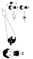
- FIG. 2 is an explanatory diagram showing an outline of the operation of the image projection system 1.
- the infrared projector 3 irradiates a projection area PA (predetermined projection plane) with a pattern image including a plurality of predetermined patterns (frames) as an infrared image.
- the imaging device 5 captures the projected pattern image included in the imaging range CA. In this case, the imaging device 5 captures the pattern image via the visible light cut filter.
- the arithmetic unit 6 performs calibration based on the pattern image (projection pattern image) projected by the infrared projection device 3 and the pattern image (captured pattern image) captured by the imaging device 5.
- the calculation device 6 uses the coordinates of the camera coordinate system (camera coordinates) used by the imaging device 5 and the coordinates of the projector coordinate system used by the infrared projection device 3 based on the positional relationship between the projection pattern image and the imaging pattern image.
- a conversion table for converting (projector coordinates) is generated.
- the image projection system 1 can associate each pixel in the image projected by the infrared projector 3 (projected image) and the image captured by the imaging device 5 (captured image).
- the projected image is a content image to be projected, for example.
- a conversion table including conversion parameters between pixels obtained by calibration is used for correcting the projection position of the projected image by the infrared projector 3.
- the imaging device 5 images the subject including the person 2 located in the imaging range CA without passing through the visible light cut filter 19.
- the arithmetic device 6 detects a face area 2 ⁇ / b> A included in the person 2.
- the position of the detected face area 2A is indicated by camera coordinates. Therefore, the arithmetic device 6 converts the detected position of the face area 2A into projector coordinates based on the conversion table.
- the infrared projector 3 projects a content image (for example, a warning image) so as to overlap the entire face area 2A based on the position of the face area 2A expressed in projector coordinates.
- the image projection system 1 associates the camera coordinates with the projector coordinates and applies to the face area of the person 2 to be imaged. , Can project content images. Therefore, the image projection system 1 can superimpose a warning image in accordance with the face that is a specific area of the person 2 to be imaged. Therefore, even if the person who confirms the captured image confirms the captured image, it is difficult to specify the face of the person 2.
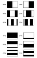
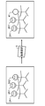
- FIG. 3 is an explanatory diagram showing an example of a projection pattern image.
- the projection pattern image is obtained by Manchester-encoding each bit obtained by gray-coding the X and Y coordinates of the DMD 12 having a predetermined number of pixels (for example, 1024 ⁇ 768 pixels) and expressing it as a monochrome binary image.
- the position information in the projector coordinates and the position information in the camera coordinates are associated with each other using the projection pattern image and the captured pattern image.
- coordinate information is coded by assigning 10 bits to both the X coordinate and the Y coordinate.
- the X coordinate is a coordinate indicating a position in the left-right direction
- the Y coordinate is a coordinate indicating a position in the vertical direction.
- X4a and X4b are a pattern image showing the ninth bit, which is the most significant bit of the X coordinate, and a pattern image whose luminance is inverted as its complementary image.
- X3a and X3b are a pattern image indicating the eighth bit of the X coordinate and a pattern image whose luminance is inverted as a complementary image thereof.
- X2a and X2b are a pattern image showing the seventh bit of the X coordinate and a pattern image whose luminance is inverted as a complementary image thereof.
- Y4a and Y4b are a pattern image showing the ninth bit, which is the most significant bit of the Y coordinate, and a pattern image whose luminance is inverted as its complementary image.
- Y3a and Y3b are a pattern image indicating the eighth bit of the Y coordinate and a pattern image whose luminance is inverted as a complementary image thereof.
- Y2a and Y2b are a pattern image showing the seventh bit of the Y coordinate and a pattern image whose luminance is inverted as its complementary image.
- the infrared projector 3 projects the projection pattern image including such 20 pairs of mutually complementary images sequentially onto the person 2 within a predetermined time.
- the imaging device 5 captures the projection pattern image and generates an imaging pattern image.
- the arithmetic device 6 compares the projection pattern image with the captured pattern image. Thereby, the arithmetic unit 6 can associate each pixel in the projected image with each pixel in the captured image. Further, the arithmetic device 6 can execute processing for tracking the changing person 2.
- the number of image patterns is 1024 ⁇ 768 pixels and the number of image patterns is 40 (40 frames).
- the number of image patterns varies depending on resolution and desired accuracy.
- either the Y coordinate or the X coordinate may be fixedly associated with the imaging device 5 and the infrared projection device 3.
- the deviation between the camera coordinate system and the projector coordinate system may be set to be limited to a narrow range in the projection range PA and the imaging range CA. Thereby, the image projection system 1 can reduce or greatly reduce the coordinate code of either the X coordinate or the Y coordinate.
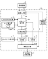
- FIG. 4 is a block diagram illustrating a functional configuration example of the arithmetic device 6.
- the arithmetic device 6 includes a pattern generation unit 21, an image output unit 22, an image input unit 23, a pattern decoding unit 24, a frame memory unit 25, a code decoding memory unit 26, a coordinate conversion unit 27, a content generation unit 30, and a content memory unit. 31 and a face detection processing unit 32.
- the pattern generation unit 21 stores the projection pattern image illustrated in FIG.
- the pattern generation unit 21 sequentially outputs information on each pattern constituting the projection pattern image toward the image output unit 22 at a predetermined timing.
- the image output unit 22 supplies an image signal corresponding to each pattern of the projection pattern image to the infrared projector 3.
- the image output unit 22 transmits the image output timing of the projection pattern image to the image input unit 23.
- the image input unit 23 controls the imaging device 5 so as to capture images in synchronization with the image output unit 22.
- the image input unit 23 acquires and inputs a captured image captured by the imaging device 5. Acquisition of a captured image is performed by wired or wireless communication, for example.
- the wired communication includes, for example, a coaxial cable, PLC (Power Line Communication), and DECT (Digital Enhanced Cordless Telecommunication).
- the wireless communication includes, for example, a wireless LAN (Local Area Network) and Bluetooth (registered trademark).
- the captured image includes, for example, an captured pattern image and an image including a subject such as a person 2.
- the captured image includes an infrared image (for example, a projection pattern image) and a visible light image.
- the image input unit 23 sends the input captured pattern image to the pattern decoding unit 24.
- the image input unit 23 sends a captured image including a subject including the person 2 to the face detection processing unit 32.
- the pattern decoding unit 24 stores, in the frame memory unit 25, the first complementary image pair (herein referred to as the other) with respect to the captured pattern image from the image input unit 23.
- the pattern decoding unit 24 acquires the second complementary image pair (here, one) regarding the captured pattern image from the image input unit 23, the pattern decoding unit 24 and the frame memory unit 25
- the difference between frames with the other of the complementary image pairs stored previously is calculated.
- the image projection system 1 can easily determine the pixel values (here, “0” and “1”) of the captured pattern image while suppressing the influence of ambient light and the like.
- a writing area is provided for each pixel of the imaging device 5 (each pixel of the captured image).
- the pattern decoding unit 24 writes each bit value of the gray-coded coordinate data in a bit unit in a writing area corresponding to each pixel in the code decoding memory unit 26.
- the pattern decoding unit 24 performs this processing for the number of image patterns (for example, 40 frames), and each pixel (in the infrared image of the infrared projector 3 corresponding to each pixel (camera coordinate system) of the captured image of the imaging device 5 (camera coordinate system).
- a 10-bit value indicating each of the X coordinate and Y coordinate of the projector coordinate system is obtained.
- the pattern decoding unit 24 writes the 10-bit value in the code decoding memory unit 26.
- the code decoding memory unit 26 finally stores correspondence information of each pixel between a projected image (for example, a projected pattern image) and a captured image (captured pattern image). Each time one complementary image pair is processed by the pattern decoding unit 24, the latest pixel correspondence information is obtained. That is, the code decoding memory unit 26 holds correspondence information between the projector coordinates and the camera coordinates for each pixel. The correspondence information of each pixel is included in the conversion table 26T of the code decoding memory unit 26.
- the face detection processing unit 32 detects the face area 2A of the person 2 included in the captured image from the image input unit 23.
- the detection of the face area 2A is performed by, for example, the Viola-Jones method.
- the face detection processing unit 32 sends the detected position information of the face area 2 ⁇ / b> A of the person 2, that is, the coordinates (camera coordinates) of the face area 2 ⁇ / b> A to the coordinate conversion unit 27.
- the coordinate conversion unit 27 converts the position of each pixel of the captured image from the camera coordinates to the projector coordinates based on the correspondence information held in the conversion table 26T. That is, the coordinate conversion unit 27 receives the camera coordinates of the face area 2A from the face detection processing unit 32, refers to the conversion table 26T, and converts the camera coordinates of the face area 2A into projector coordinates.
- the content memory unit 31 stores data (for example, character data, texture data, moving image data, mesh data, shader program, etc.) that is a material of an image (for example, a content image) to be projected on the person 2. This data is read into the content generation unit 30 in response to a request from the content generation unit 30.
- data for example, character data, texture data, moving image data, mesh data, shader program, etc.
- the content generation unit 30 generates a content image to be mapped to the face area 2A of the person 2 based on the calibration information, that is, the correspondence information of the conversion table 26T.
- the projection content images are sequentially output toward the image output unit 22.
- the content image includes, for example, a warning image for warning a camera photographer or obstructing imaging by the camera. Therefore, it can be said that the warning image is also an interference image.
- the content generation unit 30 receives the projector coordinate information of the face area 2A from the coordinate conversion unit 27.
- the content generation unit 30 generates position information (projection position information) on which the content image is projected based on the projector coordinates of the face area 2A.
- position information projection position information
- the content generation unit 30 generates projection position information by matching the center coordinates of the face region 2A with the center coordinates of the content image.
- the content generation unit 30 generates information on the size (content size) on which the content image is projected.
- the content generation unit 30 sets the content size to be equal to or wider than the face area 2A. That is, the face area 2 ⁇ / b> A is covered with the content image projected by the infrared projector 3.
- the content size may be input by the user via the operation unit of the arithmetic device 6 as long as the content size is equal to or wider than the face area 2A.
- the content generation unit 30 generates information on the shape (content shape) on which the content image is projected.
- the content generation unit 30 may make the shape of the content image corresponding to the face area 2A the same as the detected shape of the face area 2A, or a simpler shape (for example, a circular shape or a rectangular shape) from the detected shape of the face area 2A. , Other polygonal shapes).
- the content shape may be the shape of a content image stored in advance in the content memory unit 31 without being specifically determined. In this case, the content generation unit 30 does not generate content shape information.
- the image output unit 22 receives a content image, projection position information, content size information, and content shape information from the content generation unit 30, and receives an infrared image based on the content image, projection position information, content size information, and content shape information. A signal is supplied to the infrared projector 3.
- the computing device 6 is composed of a computer equipped with general-purpose hardware, for example.
- the arithmetic device 6 includes, for example, a processor that executes information processing based on a predetermined control program, a volatile memory that functions as a work area of the processor, a non-volatile memory that stores a control program executed by the processor and data, and the like. Consists of.
- the arithmetic unit 6 may have a configuration including an integrated circuit made of ASIC (Application Specific Integrated Circuit) or FPGA (Field Programmable Gateway). Further, as in a third embodiment to be described later, a configuration in which functions similar to at least a part of the functions of the arithmetic device 6 are added to at least one of the infrared projector 3 and the imaging device 5 is also possible.
- FIG. 5 is a flowchart showing an example of the calibration process of the image projection system 1.
- the image projection system 1 performs calibration before projecting a content image by the infrared projection device 3 (for example, when changing the zoom setting or focus setting in the infrared projection device 3 or when changing the zoom setting or focus setting of the imaging device 5). Execute the process.
- the visible light cut filter 19 is attached to the objective lens of the imaging device 5 (S11).
- the infrared projector 3 projects the projection pattern image onto the projection range PA (S12).
- the imaging device 5 captures the projection pattern image within the imaging range CA, and obtains an imaging pattern image (S13).
- the visible light cut filter 19 is attached to the imaging device 5 (that is, the visible light cut is in an effective state), and the imaging device 5 blocks the visible light region and transmits the infrared region. To do. That is, the captured pattern image as the captured image is an infrared image.
- the imaging device 5 sends the captured pattern image to the arithmetic device 6.
- the image input unit 23 acquires the captured pattern image from the calculation device 6 and sends it to the pattern decoding unit 24.
- the pattern decoding unit 24 associates each pixel of the infrared image (projected image) projected by the infrared projection device 3 and the captured image captured by the imaging device 5 based on the captured pattern image from the image input unit 23 ( S14).
- the pattern decoding unit 24 generates a conversion table 26 ⁇ / b> T including information regarding the correspondence between the pixels.
- the conversion table 26T is held in the code decoding memory unit 26.
- the visible light cut filter 19 of the imaging device 5 is released. That is, the visible light cut filter 19 is removed from the objective lens of the imaging device 5 (S15). As a result, the calibration process ends, and the imaging device 5 can perform imaging with visible light.
- the image projection system 1 can reduce the trouble of aligning the projection range PA and the imaging range CA strictly.
- the image projection system 1 can automatically associate the camera coordinates with the projector coordinates using the conversion table 26T, manual adjustment errors can be reduced and calibration accuracy can be improved.
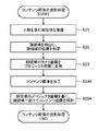
- FIG. 6 is a flowchart illustrating an example of a content image (warning image) projection process in consideration of the face area 2A of the person 2.
- the content projection process considering the face area 2A of the person 2 is performed after the calibration process shown in FIG.
- the imaging range including the person 2 is imaged by the imaging device 5 (S21).
- the imaging device 5 sends the captured image (captured image) to the arithmetic device 6.
- the image input unit 23 acquires the captured image from the imaging device 5 and sends it to the face detection processing unit 32.
- the face detection processing unit 32 detects the face area 2A of the person 2 included in the captured image (S22).
- the face detection processing unit 32 outputs position information (here, coordinate information in the camera coordinate system) of the detected face area 2A to the coordinate conversion unit 27.
- the coordinate conversion unit 27 refers to the conversion table 26T and converts each pixel into the camera coordinate projector coordinates of the face area 2A (S23).
- the coordinate conversion unit 27 sends information on the projector coordinates of the face area 2 ⁇ / b> A to the content generation unit 30.
- the content generation unit 30 acquires the content image from the content memory unit 31, and processes the content image based on the face area 2A (S24). For example, the content generation unit 30 changes the size of the content image according to the size of the face area 2A.
- the content generation unit 30 generates a content image having the same size as the face area 2A or a size larger than the face area 2A. If the range of the face area 2A overlaps the range of the content image and is hidden by the face area 2A, the shape of the content image is arbitrary.
- the content generation unit 30 Based on the projector coordinates of the face area 2A, the content generation unit 30 generates projection position information of the content image related to the projection position where the content image overlaps the entire face area 2A.
- the content generation unit 30 sends the generated (for example, processed) content image and the projection position information of the content image to the image output unit 22.
- the image output unit 22 sends the content image from the content generation unit 30 and the projection position information of the content image to the infrared projector 3. Note that content size information and shape information may be sent to the infrared projector 3.
- the infrared projection device 3 acquires the content image and the projection position information of the content image from the arithmetic device 6.
- the infrared projector 3 projects a content image with the determined content size and content shape at a position based on the coordinate information of the face area 2A in the projector coordinate system (S25). For example, the infrared projector 3 projects the content image by matching the center coordinates of the face region 2A with the center coordinates of the content image.
- the image projection system 1 projects the warning image using the projector coordinate position with respect to the camera coordinate position of the face area 2A. it can. Therefore, the face area 2A is covered with the warning image. Therefore, even if the imaging device 5 captures an imaging range including the face area 2A of the person 2, a warning image is captured. Therefore, the user who confirms the captured image cannot confirm the face of the person 2 existing in the face area 2A in the real space by the warning image. On the other hand, a part of the captured image area other than the face area 2A can be confirmed by the user.
- the image projection system 1 can protect the privacy of the person 2. Further, the image projection system 1 can appropriately protect the copyright even in a state where the copyright or the like should be taken into consideration, such as when the person 2 is playing or singing. Furthermore, the image projection system 1 can image an area other than the face area 2 ⁇ / b> A by the imaging device 5 so as to be visible according to the user's desire.
- the imaging device 5 may always shoot a subject including the person 2, periodically shoot images, or shoot at a time designated by a user or a timer.
- the shorter the imaging interval the higher the followability to the movement of the person 2. Therefore, the followability of the projection position of the warning image with respect to the face area 2A of the person 2 is enhanced.
- FIG. 7 is a schematic diagram for explaining use case 1.
- the infrared projector 3 projects a warning image 41 as a content image onto the face area 2 ⁇ / b> A of the person 2 (here, the performer of the stage 40).
- the warning image 41 is reflected in the captured image and the shooting is hindered.
- the visibility of the face area 2A is reduced by the warning image 41 being reflected in the captured image.
- FIG. 7 illustrates that the warning image 41 is projected in a circular shape, the warning image 41 may cover the face area 2A and may have another shape.
- the infrared projector 3 projects an infrared image with relatively strong light in the near-infrared region, so that even when a spectator uses a camera for capturing visible light, the captured visible light image is captured. Can be adversely affected by the warning image 41. This is because the image sensor of the camera has some sensitivity even in the near infrared region having a wavelength longer than that of visible light.
- FIG. 8 is a schematic diagram for explaining use case 2.
- FIG. 8 uses a warning image 41 including desired character information (here, a warning message “shooting prohibited!” For the audience) as the warning image 41.
- desired character information here, a warning message “shooting prohibited!” For the audience
- the image projection system 1 can effectively alert the audience who has performed unauthorized photographing.
- the content image is projected onto the face area 2 ⁇ / b> A, and the face area 2 ⁇ / b> A is covered with the warning image 41. Therefore, the image projection system 1 enables the user to confirm a part of the captured image that is not covered by the warning image 41 while appropriately protecting privacy, copyright, and the like by the warning image 41.
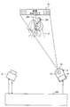
- FIG. 9 is a schematic diagram for explaining use case 3.
- FIG. 9 assumes that the image projection system 1 is used at a concert venue where photography is prohibited.
- the infrared projector 3 capable of irradiating infrared light with high light intensity projects jamming content as a warning image 41 overlapping the face region 2A.
- the performance of the performer can be confirmed as usual because the warning image 41 is not visible in the unaided eye, that is, in real space.
- the warning image 41 is superimposed on the performer's face area 2A by the infrared projection device 3 in the captured image, so that the performer's face cannot be confirmed.
- the image projection system 1 it is possible to project jamming data according to the scene. Therefore, the image projection system 1 can suppress the sneak shot of the performance of the performer by the camera. In addition, since the part other than the performer's face can be confirmed in the captured image, it is possible to confirm the part that the user pays attention to while protecting the privacy.
- the content generation unit 30 may generate the warning image 41 by reversing the pixel values of the face area 2A in the captured image in black and white. Thereby, the pixel value of the face area 2A is smoothed, and the feature of the image is diluted.
- An advertisement image or a copy-prohibited character image may be used as the warning image 41.
- the image projection system 1 may control the warning image 41 so as not to be superimposed on the face area 2A for a specific time section (for example, during CM when the concert is broadcast on television), for example, an infrared projection device The projection of the warning image 41 by 3 may be stopped.
- the image projection system 1 of the present embodiment includes the infrared projection device 3 that projects an image using infrared rays, the imaging device 5, and the arithmetic device 6.
- the arithmetic device 6 uses the camera coordinates used by the imaging device 5 and the infrared projection device based on the positional relationship between the predetermined pattern image projected by the infrared projection device 3 and the predetermined pattern image captured by the imaging device 5. Conversion information for converting the projector coordinates used by 3 is generated.
- the imaging device 5 images a subject including the person 2.
- the arithmetic device 6 detects a first position indicating a position related to the camera coordinates of a specific area in the person 2.
- the arithmetic device 6 Based on the conversion information, the arithmetic device 6 converts the information on the first position into information on the second position indicating the position related to the projector coordinates of the specific area.
- the infrared projector 3 projects a warning image overlapping all the specific areas based on the information on the second position. Infrared rays are an example of invisible light.
- the infrared projector 3 is an example of an image projector.
- the image projection system 1 can detect a specific area in the person 2 and can project the warning image 41 using infrared rays, which is an example of invisible light, in consideration of the specific area of the person 2. Therefore, the specific area of the person cannot be confirmed in the captured image while grasping the specific area of the person with the naked eye, and the privacy of the person 2 and the copyrights of the stage and the costume on which the person 2 appears can be protected. On the other hand, it is possible to confirm the area other than the specific area of the person 2. Therefore, the image projection system 1 can reduce the visibility by limiting to a part of the image area in the captured image while appropriately protecting the privacy, the copyright, and the like in the captured image.
- the specific area in the person 2 may be the face area of the person 2.
- the image projection system 1 can perform face area detection processing, which is detection processing with a relatively short processing time, and can improve real-time performance. Therefore, for example, even when the person 2 moves around on the stage, the infrared projector 3 can project a warning image with improved followability to the movement of the face region 2A.
- the arithmetic device 6 may control the size of the warning image based on the size of the face area 2A of the person 2.
- the image projection system 1 can adjust the size of the warning image 41 and cover the entire area of the face area 2 ⁇ / b> A with the warning image 41.
- the image projection system 1 can adjust the size of the warning image 41, the size of the warning image 41 previously held in the content memory unit 31 or the like can be reduced, and the amount of data for storing the warning image 41 can be reduced. . Therefore, the image projection system 1 can effectively utilize a limited memory space such as the content memory unit 31.
- the content image is projected onto the face area 2A of the person 2 as an example.
- the content image is projected at a position different from the position of the face area 2A of the person 2.
- matters different from those in the first embodiment will be mainly described, and explanations of matters similar to those in the first embodiment will be omitted or simplified.
- FIG. 10 is a block diagram illustrating a functional configuration example of the arithmetic device 6A.
- the arithmetic device 6A includes a content generation unit 30A instead of the content generation unit 30 as compared with the arithmetic device 6 of the first embodiment.
- the content generation unit 30A generates a content image to be mapped while avoiding the face area 2A of the person 2 based on the calibration information.
- the projection content images are sequentially output toward the image output unit 22.
- the content image includes, for example, a decoration image for decorating the scene where the person 2 is placed.
- the content generation unit 30A generates information on the size (content size) on which the content image is projected.
- the content size may be equal to the face area 2A, may be larger than the face area 2A, or may be smaller than the face area 2A.
- the content generation unit 30A may automatically generate the content size according to the position information of each feature region so that the content size can be contained in the region where the face region 2A and the person 2 are absent.
- the content size may be input by the user via the operation unit of the arithmetic device 6.
- the content generation unit 30A receives information on the projector coordinates of the face area 2A from the coordinate conversion unit 27.
- the content generation unit 30A generates the projection position information of the content image based on the projector coordinates of the face area 2A. For example, the content generation unit 30A generates the projection position information so that the projector coordinates of the face area 2A and the coordinates of the content image do not have overlapping portions.
- FIG. 11 is a flowchart illustrating an example of a content image (decorative image) projection process in consideration of the face area 2A of the person 2.
- the content image projection process considering the face area 2A of the person 2 is performed after the calibration process shown in FIG.
- processes similar to those in FIG. 6 are denoted by the same step numbers, and description thereof is omitted or simplified.
- the content generation unit 30A acquires a content image (decorative image) from the content memory unit 31, and processes the content image based on the face area 2A (S24A). For example, the content generation unit 30A adjusts the size of the content image so that the content image does not overlap the face area 2A.
- the content generation unit 30A may process the content shape.
- the content generation unit 30A generates the projection position information of the content image related to the projection position where the content image does not overlap the face region 2A based on the projector coordinates of the face region 2A.
- the content generation unit 30A sends the generated (for example, processed) content image and the projection position information of the content image to the image output unit 22.
- the image output unit 22 sends the content image from the content generation unit 30 ⁇ / b> A and the projection position information of the content image to the infrared projector 3. Note that content size information and shape information may be sent to the infrared projector 3.
- the infrared projection device 3 acquires the content image and the projection position information of the content image from the arithmetic device 6.
- the infrared projector 3 projects the content image (decorative image) with the determined content size and content shape onto the projection position based on the projection position information of the content image (S25A).
- the image projection system 1 projects the decoration image using the projector coordinate position while avoiding the camera coordinate position of the face area 2A. it can. Therefore, the face area 2A is not covered with the decorative image. Therefore, even when the imaging device 5 captures the imaging range CA including the face area 2A of the person 2, the face and the decoration image of the person 2 are captured without the face area 2A being covered with the decoration image. Therefore, the user who confirms the captured image can confirm the decoration image that does not exist in the real space together with the face of the person 2.
- the image projection system 1 can color various events that occur in the person 2 (for example, effects at a ceremonial occasion or an amusement park). Further, the image projection system 1 can capture the appearance and expression of the person 2 in the captured image without covering the face area 2A of the person 2 during various decorated events. Therefore, when reviewing the event in the future, it becomes easy for the confirmer who confirmed the captured image to recall the situation at the time of the event and the situation of the person 2.
- use cases of the image projection system 1 of the present embodiment will be described.
- use cases 4 and 5 shown below can be considered.
- FIG. 12 is a schematic diagram for explaining use case 4.
- the infrared projector 3 projects the decoration image 51 as an infrared image around the face area 2A without overlapping the face area 2A of the person 2.
- the decoration image 51 includes a decoration including information (here, a congratulatory message and a figure for the groom / bride) including desired characters and figures.
- An example in which an image 51 is projected is shown.
- the image projection system 1 is surprised to the photographer (such as a wedding participant) by the decorative image 51 that is visible for the first time when the image captured by the imaging device 5 is developed (or displayed on the display). Arouse joy.
- FIG. 13 is a schematic diagram for explaining use case 5.
- FIG. 13 assumes a scene in which a family commemorative photo is taken at a funeral at a funeral.
- the infrared projector 3 capable of irradiating infrared light with high light intensity irradiates the deceased image and the comment information of the individual or the bereaved family as the decoration image 51.
- the decoration image 51 is irradiated to a position that does not overlap with each face region 2A of the bereaved family. In this case, the decoration image 51 cannot be visually recognized in the real space, but when the image is captured by the camera included in the smartphone, the decoration image 51 can be visually recognized in the captured image.
- the content generation unit 30A may calculate the projection position of the decoration image 51 based on the position of the face area 2A, and project the decoration image 51 on the calculated projection position.
- the comment information in the decoration image 51 may be a thank-you comment such as “Thank you so far” or a desired comment that the deceased heard before.
- the decorative image 51 is invisible with the naked eye, an actual funeral event can proceed without delay.
- a photographed image is confirmed in the future and a funeral event is recalled, it is possible to strengthen the consideration of deceased persons such as bereaved families.
- a funeral event can be colored with the decoration image 51.
- the image projection system 1 can provide a captured image including the decorative image 51 as an added value of the funeral event, and can improve the evaluation of the funeral.
- FIG. 14 is a schematic diagram for explaining use case 6.
- FIG. 14 assumes that the image projection system 1 is used in a haunted house at a theme park.
- the infrared projector 3 capable of emitting infrared light with high light intensity projects a spirit-related image (for example, a ghost image) as the decoration image 51.
- the decoration image 51 cannot be visually recognized in the real space, but when the image is captured by the camera included in the smartphone, the decoration image 51 can be visually recognized in the captured image. Therefore, this camera can take a psychic photograph including the decorative image 51.
- the content generation unit 30A may calculate the projection position of the decoration image 51 based on the position of the face area 2A, and project the decoration image 51 on the calculated projection position.
- the person 2 who visited the haunted house confirms the ghost that did not exist in the real space in the haunted house by confirming the image captured by the camera. , I can feel more fear. Therefore, the image projection system 1 can provide a thrilling amusement system.
- the image projection system 1 can increase the types of ghosts that can be projected by holding the decoration images 51 relating to many ghost characters in the content memory unit 31. Further, the content generation unit 30A may process the decoration image 51 to decorate the ghost character. Moreover, the image projection system 1 may provide the hint of a story with respect to the guest of a theme park by including the decoration image 51 in a captured image.
- the image projection system 1 includes the infrared projection device 3 that projects an image using infrared light, the imaging device 5, and the arithmetic device 6A.
- the arithmetic device 6A is configured to use the camera coordinates and the infrared projection device used by the imaging device 5 based on the positional relationship between the predetermined pattern image projected by the infrared projection device 3 and the predetermined pattern image captured by the imaging device 5. Conversion information for converting the projector coordinates used by 3 is generated.
- the imaging device 5 images a subject including the person 2.
- the arithmetic device 6 ⁇ / b> A detects a first position indicating a position related to the camera coordinates of a specific area in the person 2.
- the arithmetic device 6A Based on the conversion information, the arithmetic device 6A converts the information on the first position into information on the second position indicating the position related to the projector coordinates of the specific area.
- the infrared projector 3 projects the decorative image 51 avoiding a specific area based on the information on the second position.
- the image projection system 1 detects a specific area in the person 2 and considers the specific area of the person 2 (for example, the face area 2A), and uses the infrared ray, which is an example of invisible light, for the decoration image 51. Can be projected. Therefore, while the human eye can visually recognize the person 2 as it is, the decorative image 51 can be confirmed in a region other than the specific region in the captured image. Therefore, the image projection system 1 can decorate the experience of the person 2 in the captured image, the state of the person at the time of the experience, the facial expression, and the like, and can color the memories of the person 2.
- the arithmetic devices 6 and 6A are provided separately.
- the calculation devices 6 and 6A are not provided separately, and the infrared projection device 3 has the function of the calculation devices 6 and 6A.
- the image projection system projects the warning image 41 onto the face area 2A as in the first embodiment, but as in the second embodiment.
- the decoration image 51 may be projected while avoiding the face area 2A.
- FIG. 15 is a schematic diagram showing an example of the image projection system 1B.
- the image projection system 1B includes an infrared projection device 3B and an imaging device 5.
- the description of the same configuration as that of the image projection system 1 in the first and second embodiments shown in FIG. 1 is omitted or simplified.
- the infrared projector 3B includes an emitting unit 10, an infrared light source 11, a DMD 12, a controller 13, a processor 14, and a communication device 15.
- the controller 13 is formed by, for example, MEMS (Micro Electro Mechanical Systems), and controls the operation of the infrared light source 11 and the DMD 12.
- the communication device 15 is connected to the imaging device 5 by wire or wireless.
- the communication device 15 wirelessly communicates with the imaging device 5 using, for example, a wireless LAN or Bluetooth (registered trademark), and acquires a captured image.
- the processor 14 is configured by, for example, an FPGA (Field Programmable Gate Array).
- the processor 14 has substantially the same function as the arithmetic device 6 or the arithmetic device 6B. That is, the processor 14 includes the pattern generation unit 21B, the image output unit 22B, the image input unit 23B, the pattern decoding unit 24B, the frame memory unit 25B, the code decoding memory unit 26B, the coordinate conversion unit 27B, the content generation unit 30B, and the content memory. Unit 31B and face detection processing unit 32B.
- FIG. 16 is a block diagram illustrating a configuration example of the processor 14.
- “B” is added to the end of the reference numerals of the components, which is added to distinguish the configuration of the arithmetic unit 6 from the configuration of the processor 14. Yes, the function is similar.
- the image input unit 23B of the processor 14 transmits and receives data to and from the communication device 15, unlike the image input unit 23 of the arithmetic device 6.
- the image output unit 22B of the processor 14 is different from the image output unit 22 of the arithmetic device 6 in that the data output destination is the infrared light source 11.
- the infrared projector 3 is projected by the infrared light source 11 that projects an image using infrared rays, the communication device 15 that acquires an image captured by the imaging device 5, and the infrared light source 11.
- Conversion information for converting the camera coordinates used by the imaging device 5 and the projector coordinates used by the infrared projection device 3 based on the positional relationship between the predetermined pattern image and the predetermined pattern image captured by the imaging device 5.
- the processor 14 which produces
- the processor 14 detects a first position indicating a position related to the camera coordinates of a specific region in the person 2 included in the subject imaged by the imaging device 5, and obtains information on the first position based on the conversion information. Then, the information is converted into the second position information indicating the position related to the projector coordinates of the specific area.
- the infrared light source 11 projects the warning image 41 on the entire specific area based on the information on the second position.
- the infrared light source 11 is an example of a projection unit.
- the communication device 15 is an example of an acquisition unit.
- the processor 14 is an example of a processing unit.
- the infrared projection device 3 can detect a specific area in the person 2 and can project the warning image 41 using infrared light which is an example of invisible light in consideration of the specific area of the person 2. For this reason, the specific area of the person 2 can be grasped by the naked eye, but the specific area cannot be confirmed in the captured image, and the privacy of the person 2 and the copyright of the stage or costume on which the person 2 appears can be protected. On the other hand, it is possible to confirm the area other than the specific area of the person 2. Therefore, the infrared projection device 3 can reduce the visibility by limiting only a part of the image area in the captured image while appropriately protecting privacy, copyright, and the like in the captured image.
- the infrared projector 3 has the function of the arithmetic device 6 of the first and second embodiments, it is not necessary to provide the arithmetic device 6 separately. Therefore, the installation space for the arithmetic device 6 can be reduced, and the cost required for the arithmetic device 6 can be reduced.
- the image projection apparatus projects an image using infrared rays, but the image may be projected using non-visible light (for example, ultraviolet rays) other than infrared rays.
- non-visible light for example, ultraviolet rays
- the content image when there are a plurality of captured images, the content image is projected so as to overlap all of the plurality of face regions 2A.
- the content image when there are a plurality of captured images, the content image is projected so as to avoid all of the plurality of face areas 2A, that is, not to overlap with all of the plurality of face areas 2A.
- the infrared projection device 3 may project the content image so as to overlap the face area 2A by limiting to the specific face area 2A among the face areas 2A of the plurality of persons 2.
- the subject imaged by the imaging device 5 may include a plurality of persons 2.
- the infrared projector 3 may project a warning image onto a second position indicating a position related to the projector coordinates of the face area 2A of a specific person among the plurality of persons 2.
- the image projection system 1 can capture an image with the imaging device 5 even when the person 2 who does not wish to take an image with the imaging device 5 and the person 2 who wants to take an image with the imaging device 5 coexist. Even in this case, the image projection system 1 can hide the periphery of the face area of the person 2 who does not wish to capture with the warning image, and can appropriately protect the privacy of the person 2.
- FIG. 17 is a schematic diagram showing a first projection example of the warning image 41 when there are a plurality of persons 2.
- FIG. 17 illustrates that there are two persons 2A1 who want to take an image as an example other than a specific person, and there is one person 2A2 who does not want to take an image as an example of a specific person.
- the warning image 41 is not projected on the person 2A1 who wants to take an image, and the warning image 41 is projected on the person 2A2 who does not want to take an image.
- the infrared projector 3 may project a warning image on a second position indicating a position related to the projector coordinates of the face area 2A of a person other than the specific person among the plurality of persons 2.
- the image projection system 1 can pick up an image with the image pickup device 5 even when, for example, a person 2 who is a theater performer and a person 2 who is a spectator are mixed. Even in this case, the image projection system 1 can protect the privacy by hiding the audience face area 2A by the warning image while improving the advertising effect without hiding the face area 2A of the theater performer in the captured image.
- FIG. 18 is a schematic diagram illustrating a second projection example of the warning image 41 when there are a plurality of persons 2.
- FIG. 18 illustrates that there are two theater performers 2A3 as an example of a specific person and one audience 2A4 as an example other than the specific person.
- the warning image 41 is not projected on the performer 2A3 and the face can be confirmed, and the warning image 41 is projected on the audience 2A4 and the face cannot be confirmed.
- the face area 2A is mainly exemplified as the specific area of the person 2, but it may be other than the face area 2A.
- the warning image 41 may be projected so as to overlap the entire partial area of the person 2 corresponding to the costume part.
- a part such as a costume may be performed by, for example, image feature extraction from a captured image, or a user operation for designating a region such as a costume may be received by an operation unit.
- the image projection system 1 can protect copyrights etc. appropriately.
- the processor including the controller may be physically configured in any manner. Further, if a programmable processor is used, the processing contents can be changed by changing the program, so that the degree of freedom in designing the processor can be increased.
- the processor may be composed of one semiconductor chip or physically composed of a plurality of semiconductor chips. When configured by a plurality of semiconductor chips, each control of the first to third embodiments may be realized by different semiconductor chips. In this case, it can be considered that a plurality of semiconductor chips constitute one processor.
- the processor may be configured by a member (capacitor or the like) having a function different from that of the semiconductor chip. Further, one semiconductor chip may be configured so as to realize the functions of the processor and other functions.
- a plurality of processors may be configured by one processor.
- the present disclosure is useful for an image projecting system, an image projecting device, an image projecting method, and the like that can reduce visibility only in a part of an image area in a captured image.
Landscapes
- Engineering & Computer Science (AREA)
- Physics & Mathematics (AREA)
- Multimedia (AREA)
- General Physics & Mathematics (AREA)
- Theoretical Computer Science (AREA)
- Signal Processing (AREA)
- Human Computer Interaction (AREA)
- Oral & Maxillofacial Surgery (AREA)
- General Health & Medical Sciences (AREA)
- Health & Medical Sciences (AREA)
- Computer Hardware Design (AREA)
- Geometry (AREA)
- Artificial Intelligence (AREA)
- Computer Vision & Pattern Recognition (AREA)
- Projection Apparatus (AREA)
- Controls And Circuits For Display Device (AREA)
- Transforming Electric Information Into Light Information (AREA)
Priority Applications (1)
| Application Number | Priority Date | Filing Date | Title |
|---|---|---|---|
| US16/468,638 US10750142B2 (en) | 2016-12-13 | 2017-09-22 | Image projection system, image projection device, and image projection method |
Applications Claiming Priority (2)
| Application Number | Priority Date | Filing Date | Title |
|---|---|---|---|
| JP2016-241378 | 2016-12-13 | ||
| JP2016241378A JP2018097148A (ja) | 2016-12-13 | 2016-12-13 | 画像投影システム、画像投影装置、及び画像投影方法 |
Publications (1)
| Publication Number | Publication Date |
|---|---|
| WO2018110022A1 true WO2018110022A1 (ja) | 2018-06-21 |
Family
ID=62558298
Family Applications (1)
| Application Number | Title | Priority Date | Filing Date |
|---|---|---|---|
| PCT/JP2017/034231 WO2018110022A1 (ja) | 2016-12-13 | 2017-09-22 | 画像投影システム、画像投影装置、及び画像投影方法 |
Country Status (3)
| Country | Link |
|---|---|
| US (1) | US10750142B2 (de) |
| JP (1) | JP2018097148A (de) |
| WO (1) | WO2018110022A1 (de) |
Families Citing this family (7)
| Publication number | Priority date | Publication date | Assignee | Title |
|---|---|---|---|---|
| WO2019054204A1 (ja) * | 2017-09-14 | 2019-03-21 | ソニー株式会社 | 画像処理装置および方法 |
| JP7285470B2 (ja) | 2018-05-17 | 2023-06-02 | パナソニックIpマネジメント株式会社 | 投影システム、投影装置及び投影方法 |
| JP7467883B2 (ja) * | 2019-04-29 | 2024-04-16 | セイコーエプソン株式会社 | 回路装置、電子機器及び移動体 |
| JP2022032483A (ja) * | 2020-08-12 | 2022-02-25 | キヤノン株式会社 | 画像処理装置、画像処理方法、およびプログラム |
| JP7184072B2 (ja) * | 2020-10-23 | 2022-12-06 | セイコーエプソン株式会社 | 特定方法、特定システム、及びプログラム |
| JP2022102058A (ja) | 2020-12-25 | 2022-07-07 | セイコーエプソン株式会社 | 位置特定方法、シミュレーション方法、位置特定システムおよびシミュレーションシステム |
| US12075200B2 (en) * | 2021-09-17 | 2024-08-27 | Casio Computer Co., Ltd. | Projecting system, projecting method, and storage medium |
Citations (5)
| Publication number | Priority date | Publication date | Assignee | Title |
|---|---|---|---|---|
| JP2002044582A (ja) * | 2000-07-24 | 2002-02-08 | Casio Comput Co Ltd | 収録・再生方法及び収録・再生システム |
| JP2004062560A (ja) * | 2002-07-30 | 2004-02-26 | Omron Corp | 顔照合装置および顔照合方法 |
| US20060159302A1 (en) * | 2004-12-03 | 2006-07-20 | Interdigital Technology Corporation | Method and apparatus for generating, sensing and adjusting watermarks |
| JP2013161400A (ja) * | 2012-02-08 | 2013-08-19 | Nec Casio Mobile Communications Ltd | 携帯端末、撮影画像公開方法、プログラム |
| JP2015173431A (ja) * | 2014-02-18 | 2015-10-01 | パナソニック インテレクチュアル プロパティ コーポレーション オブアメリカPanasonic Intellectual Property Corporation of America | 投影システムおよび半導体集積回路 |
Family Cites Families (6)
| Publication number | Priority date | Publication date | Assignee | Title |
|---|---|---|---|---|
| US6554431B1 (en) * | 1999-06-10 | 2003-04-29 | Sony Corporation | Method and apparatus for image projection, and apparatus controlling image projection |
| WO2005089213A2 (en) | 2004-03-12 | 2005-09-29 | Interdigital Technology Corporation | Watermarking of recordings |
| US20070242852A1 (en) | 2004-12-03 | 2007-10-18 | Interdigital Technology Corporation | Method and apparatus for watermarking sensed data |
| US7321761B2 (en) | 2004-12-03 | 2008-01-22 | Interdigital Technology Corporation | Method and apparatus for preventing unauthorized data from being transferred |
| JP5161655B2 (ja) | 2008-05-22 | 2013-03-13 | 日本放送協会 | 盗撮防止装置 |
| JP2017215374A (ja) | 2016-05-30 | 2017-12-07 | パナソニックIpマネジメント株式会社 | 画像投影システムおよび画像投影方法 |
-
2016
- 2016-12-13 JP JP2016241378A patent/JP2018097148A/ja active Pending
-
2017
- 2017-09-22 US US16/468,638 patent/US10750142B2/en active Active
- 2017-09-22 WO PCT/JP2017/034231 patent/WO2018110022A1/ja active Application Filing
Patent Citations (5)
| Publication number | Priority date | Publication date | Assignee | Title |
|---|---|---|---|---|
| JP2002044582A (ja) * | 2000-07-24 | 2002-02-08 | Casio Comput Co Ltd | 収録・再生方法及び収録・再生システム |
| JP2004062560A (ja) * | 2002-07-30 | 2004-02-26 | Omron Corp | 顔照合装置および顔照合方法 |
| US20060159302A1 (en) * | 2004-12-03 | 2006-07-20 | Interdigital Technology Corporation | Method and apparatus for generating, sensing and adjusting watermarks |
| JP2013161400A (ja) * | 2012-02-08 | 2013-08-19 | Nec Casio Mobile Communications Ltd | 携帯端末、撮影画像公開方法、プログラム |
| JP2015173431A (ja) * | 2014-02-18 | 2015-10-01 | パナソニック インテレクチュアル プロパティ コーポレーション オブアメリカPanasonic Intellectual Property Corporation of America | 投影システムおよび半導体集積回路 |
Also Published As
| Publication number | Publication date |
|---|---|
| US20200099906A1 (en) | 2020-03-26 |
| US10750142B2 (en) | 2020-08-18 |
| JP2018097148A (ja) | 2018-06-21 |
Similar Documents
| Publication | Publication Date | Title |
|---|---|---|
| WO2018110022A1 (ja) | 画像投影システム、画像投影装置、及び画像投影方法 | |
| CN112954288B (zh) | 图像投影系统和图像投影方法 | |
| JP6732716B2 (ja) | 画像生成装置、画像生成システム、画像生成方法、およびプログラム | |
| JP2020060599A (ja) | 撮像装置組立体、3次元形状測定装置及び動き検出装置、並びに、3次元形状の測定方法 | |
| JP2009194644A (ja) | 画像処理装置,画像処理方法及び撮像装置 | |
| CN109639959B (zh) | 图像处理装置、图像处理方法以及记录介质 | |
| KR101767853B1 (ko) | 정보 처리 장치, 화상 투영 시스템 및 컴퓨터 프로그램 | |
| CN108781268B (zh) | 图像处理装置和方法 | |
| JP2008017386A (ja) | キー画像生成装置 | |
| JP2009141508A (ja) | テレビ会議装置、テレビ会議方法、プログラムおよび記録媒体 | |
| JP6429165B2 (ja) | カメラ及び照明システム | |
| JP3139996U (ja) | 眩しくないフラッシュ撮影装置 | |
| Kawabe et al. | Deformation lamps: A projection technique to make a static picture dynamic | |
| US20180292867A1 (en) | Method for recording an image using a mobile device | |
| JP2021129293A (ja) | 画像処理装置、画像処理システム、画像処理方法およびプログラム | |
| JP6995554B2 (ja) | 撮像装置および撮像方法 | |
| WO2018082220A1 (zh) | 全景相机以及深度信息获取方法 | |
| JP2007033264A (ja) | 証明写真撮影装置及び証明写真撮影方法 | |
| JP4491599B2 (ja) | 像分離装置 | |
| JP6429164B2 (ja) | カメラ及び照明システム | |
| JP7530680B1 (ja) | 花畑の照明システム、制御装置及び照明方法 | |
| JP2010161452A (ja) | 赤外線照射式撮像装置 | |
| JP2002260017A (ja) | 3次元形状データ生成方法および装置 | |
| WO2023047643A1 (ja) | 情報処理装置、映像処理方法、プログラム | |
| WO2024042893A1 (ja) | 情報処理装置、情報処理方法、およびプログラム |
Legal Events
| Date | Code | Title | Description |
|---|---|---|---|
| 121 | Ep: the epo has been informed by wipo that ep was designated in this application |
Ref document number: 17882199 Country of ref document: EP Kind code of ref document: A1 |
|
| NENP | Non-entry into the national phase |
Ref country code: DE |
|
| 122 | Ep: pct application non-entry in european phase |
Ref document number: 17882199 Country of ref document: EP Kind code of ref document: A1 |