WO2018105451A1 - Fin unit device and ship provided with same - Google Patents
Fin unit device and ship provided with same Download PDFInfo
- Publication number
- WO2018105451A1 WO2018105451A1 PCT/JP2017/042710 JP2017042710W WO2018105451A1 WO 2018105451 A1 WO2018105451 A1 WO 2018105451A1 JP 2017042710 W JP2017042710 W JP 2017042710W WO 2018105451 A1 WO2018105451 A1 WO 2018105451A1
- Authority
- WO
- WIPO (PCT)
- Prior art keywords
- fin
- duct
- propeller
- ship
- rotation axis
- Prior art date
Links
Images


Classifications
-
- B—PERFORMING OPERATIONS; TRANSPORTING
- B63—SHIPS OR OTHER WATERBORNE VESSELS; RELATED EQUIPMENT
- B63H—MARINE PROPULSION OR STEERING
- B63H5/00—Arrangements on vessels of propulsion elements directly acting on water
- B63H5/07—Arrangements on vessels of propulsion elements directly acting on water of propellers
- B63H5/16—Arrangements on vessels of propulsion elements directly acting on water of propellers characterised by being mounted in recesses; with stationary water-guiding elements; Means to prevent fouling of the propeller, e.g. guards, cages or screens
Definitions
- the present invention relates to a fin unit device for improving a flow field upstream of a propeller and a ship equipped with the same.
- Patent Documents 1 and 2 disclose a configuration in which a cylindrical front nozzle fixed to a bossing is provided so that external fins protrude outward. Furthermore, it is described that the preliminary swirl can be optimized by having different angles of attack between the outer fin and the inner fin.
- Patent Document 3 discloses that the angle of attack between the external fin and the internal fin is different.
- the flow field on the upstream side of the propeller is complicated and the flow direction is different at each position.
- the angle of attack determined by the installation angle is not fixed uniformly. That is, if fins are installed at different positions, the angle of attack of each fin will be different even if the fin installation angle is the same. Therefore, the matter of disposing fins at different angles of attack disclosed in Patent Document 3 does not make technical sense and does not indicate specific problem solving means.
- This invention is made in view of such a situation, Comprising:
- the fin unit apparatus which can improve the propulsion performance of a ship by improving the flow field of a propeller upstream, and a ship provided with the same are provided.
- the fin unit apparatus which can improve the propulsion performance of a ship by improving the flow field of a propeller upstream, and a ship provided with the same are provided.
- the fin unit apparatus which can improve the propulsion performance of a ship by improving the flow field of a propeller upstream, and a ship provided with the same are provided.
- the fin unit device of the present invention and a ship equipped with the same employ the following means.
- a fin unit device includes a duct that is located in front of a propeller vessel and is fixed to a boshing side so as to surround a rotation axis of the propeller, and an outer end portion on an inner peripheral side of the duct.
- An inner fin that is fixed and extends radially inward toward the rotational axis, and is positioned in the extending direction of the inner fin, and an inner end is fixed to the outer peripheral side of the duct, and is radially outward.
- at least a pair of the inner fin and the outer fin are on the port side when the propeller is rotated clockwise as viewed from the rear of the ship, or is rotated counterclockwise when the propeller is viewed from the rear of the ship.
- the inner fin and the outer fin fixed to the duct located in front of the propeller ship promote the pre-turning upstream of the propeller to improve the propeller efficiency. Since the inner fin and the outer fin are fixed to the duct, the inner fin and the outer fin can be easily installed via the duct even if the inner fin and the outer fin have different installation angles.
- the upstream side of the propeller becomes a complicated flow field due to the hull shape such as bossing. For example, in a plane orthogonal to the propeller rotation axis, the flow from the upper side to the lower side is mainly on the inner peripheral side centered on the propeller rotation axis, and the flow from the lower side to the upper side is mainly along the circumferential direction on the outer peripheral side. It becomes.
- the installation angle between the inner fin and the outer fin can be optimized by paying attention to this flow field. Specifically, an angle of attack is formed with respect to the inflowing water on the starboard side in the case of propeller right rotation (starboard side in the case of propeller left rotation), and the inner fin relative to the reference plane including the rotation axis is formed.
- the installation angle is ⁇ i and the installation angle of the outer fin with respect to the reference plane is ⁇ o, the relationship ⁇ i> ⁇ o is established. The reason is as follows.
- the flow field on the inner peripheral side is mainly the flow from the upper side to the lower side, and the direction facing the propeller rotating from the lower side to the upper side. Become. For this reason, it is preferable to increase the installation angle ⁇ i of the inner fin so as to promote the flow from the upper side to the lower side.
- the flow field on the outer peripheral side is mainly from the bottom to the top, and is in the same direction as the propeller rotating from the bottom to the top. For this reason, it is preferable that the outer fin has an installation angle that changes the flow downward.
- the installation angle ⁇ o of the outer fin is set smaller than the installation angle ⁇ i of the inner fin ( ⁇ i> ⁇ o).
- the flow field on the upstream side of the propeller is improved on the inner peripheral side and the outer peripheral side, and the propulsion performance of the ship can be improved.
- the fin unit device includes a duct that is positioned in front of the propeller and is fixed to the boshing side so as to surround the rotation axis of the propeller, and an outer end on the inner peripheral side of the duct.
- the inner fin is fixed in the radial direction toward the rotation axis, the inner fin is positioned in the extending direction of the inner fin, and the inner end is fixed on the outer peripheral side of the duct.
- at least a pair of the inner fin and the outer fin when the propeller rotates clockwise when viewed from the rear of the ship, or when the propeller is viewed from the rear of the ship.
- the installation angle of the inner fin with respect to the reference plane including the rotation axis is ⁇ i
- the outer fin with respect to the reference plane is The ⁇ degree when the .theta.o, there is a .theta.i ⁇ .theta.o.
- the inner fin and the outer fin fixed to the duct located in front of the propeller ship promote the pre-turning upstream of the propeller to improve the propeller efficiency. Since the inner fin and the outer fin are fixed to the duct, the inner fin and the outer fin can be easily installed via the duct even if the inner fin and the outer fin have different installation angles.
- the upstream side of the propeller becomes a complicated flow field due to the hull shape such as bossing. For example, in a plane orthogonal to the propeller rotation axis, the flow from the upper side to the lower side is mainly on the inner peripheral side centered on the propeller rotation axis, and the flow from the lower side to the upper side is mainly along the circumferential direction on the outer peripheral side. It becomes.
- the installation angle between the inner fin and the outer fin can be optimized by paying attention to this flow field.
- the angle of attack is formed on the starboard side (portal side in the case of propeller left rotation) with respect to the inflowing water, and the inner fin relative to the reference plane including the rotation axis is formed.
- the installation angle is ⁇ i and the installation angle of the outer fin with respect to the reference plane is ⁇ o, the relationship ⁇ i ⁇ o is established.
- the flow field on the inner peripheral side mainly flows from the upper side to the lower side, and is in the same direction as the propeller rotating from the upper side to the lower side. For this reason, it is preferable to increase the installation angle ⁇ i so that the inner fin changes its flow upward.
- the flow field on the outer peripheral side is mainly from the bottom to the top, and is in a direction facing the propeller rotating from the bottom to the top. For this reason, it is preferable to increase the installation angle ⁇ o of the outer fin so as to promote the flow from the lower side to the upper side.
- the installation angle ⁇ o of the outer fin is set larger than the installation angle ⁇ i of the inner fin ( ⁇ i ⁇ o).
- the flow field upstream of the propeller is improved on the inner peripheral side and the outer peripheral side, and the propulsion performance can be improved.
- the fin unit device includes a duct that is positioned in front of the propeller and is fixed to the boshing side so as to surround the rotation axis of the propeller, and an outer end on the inner peripheral side of the duct.
- the inner fin extending radially inward toward the rotation axis and the inner end fixed to the outer peripheral side of the duct at a position different from the extending direction of the inner fin.
- an outer fin extending outward in the direction.
- the inner fin and the outer fin fixed to the duct located in front of the propeller ship promote the pre-turning upstream of the propeller to improve the propeller efficiency. Since the inner fin and the outer fin are fixed to the duct, the inner fin and the outer fin can be easily installed via the duct even if the inner fin and the outer fin have different installation angles.
- the upstream side of the propeller becomes a complicated flow field due to the hull shape such as bossing. For example, in a plane orthogonal to the propeller rotation axis, the flow from the upper side to the lower side is mainly on the inner peripheral side centered on the propeller rotation axis, and the flow from the lower side to the upper side is mainly along the circumferential direction on the outer peripheral side. It becomes.
- the inventors have found that the installation angle between the inner fin and the outer fin can be optimized by paying attention to this flow field.
- the outer fin is provided at a position different from the extending direction of the inner fin.
- Inner fins and outer fins can be installed at appropriate positions independently on the inner and outer circumferential sides, which have different flow fields, and the flow field upstream of the propeller is improved on the inner and outer circumferential sides. Can be improved.
- the outer fin is not provided below the duct.
- the outer peripheral side below the duct is a region where the flow velocity in the direction of the propeller rotation axis is large, and the outer fin may become a resistance. Therefore, the outer fin is not provided below the duct. In such a case, the number of outer fins may be smaller than the number of inner fins.
- the lower part of the duct means, for example, a region below a horizontal line passing through the propeller rotation axis when the duct is viewed from the rear of the ship.
- the propeller is on the starboard side when the propeller is rotated rightward when viewed from the rear of the ship, or the starboard side when the propeller is rotated left when viewed from the rear of the ship.
- the inner end of the outer fin is fixed to the duct at a position above the corresponding inner fin.
- the fin unit device includes a duct that is positioned in front of the propeller and is fixed to the boshing side so as to surround the rotation axis of the propeller, and an outer end on the inner peripheral side of the duct.
- the inner fin is fixed in the radial direction toward the rotation axis, the inner fin is positioned in the extending direction of the inner fin, and the inner end is fixed on the outer peripheral side of the duct.
- the inner fin and the outer fin fixed to the duct located in front of the propeller ship promote the pre-turning upstream of the propeller to improve the propeller efficiency. Since the inner fin and the outer fin are fixed to the duct, the inner fin and the outer fin can be easily installed via the duct even if the inner fin and the outer fin have different installation angles.
- the upstream side of the propeller becomes a complicated flow field due to the hull shape such as bossing. For example, in a plane orthogonal to the propeller rotation axis, the flow from the upper side to the lower side is mainly on the inner peripheral side centered on the propeller rotation axis, and the flow from the lower side to the upper side is mainly along the circumferential direction on the outer peripheral side. It becomes.
- the installation angle between the inner fin and the outer fin can be optimized by paying attention to this flow field.
- the extending direction in the radial direction of the outer fin is set in the radial direction of the corresponding inner fin. It was made to face upwards from the extending direction. Thereby, a flow can be changed in the direction which opposes the propeller which rotates upwards from the downward direction.
- the port side upper side in the case of propeller left rotation, on the starboard side
- the port side upper side is, for example, an area above the horizontal line passing through the propeller rotation axis when viewed from the rear of the ship. Means.
- the duct has a wing-shaped longitudinal section in which a cord length direction is provided so as to incline from the upstream side toward the downstream side toward the rotation axis.
- the duct has a wing-shaped longitudinal section with the cord length direction inclined to the propeller rotation axis side from the upstream side to the downstream side, the propulsive force is obtained by the flow flowing into the duct Can do.
- the cord length below the duct is smaller than the cord length above the duct.
- the cord length below the duct is made shorter than the upper one so as not to become more resistant.
- the installation angle below the duct may be set different from that above the duct so that the installation angle does not become more resistance.
- the lower part of the duct means, for example, a region below a horizontal line passing through the propeller rotation axis when the duct is viewed from the rear of the ship.
- a duct missing portion in which the duct is partially missing is provided below the duct.
- the lower part of the duct was provided with a part of the duct missing part that was partly missing to form a region where no duct was provided. Thereby, the resistance of the duct in the region where the flow separation and the flow velocity in the direction of the propeller rotation axis are large can be reduced.
- the center position when the duct is viewed from the rear of the hull is different from the rotation axis.
- the upstream side of the propeller becomes a complicated flow field due to the hull shape such as bossing.
- the duct has a region where thrust is generated as described above, and there is also a region where the duct itself becomes a resistance. Therefore, by installing the center position of the duct at a position different from the propeller rotation axis, the performance of the duct can be effectively exhibited. For example, at a position where thrust can be generated, such as above the duct, the duct is positioned at a position where thrust can be effectively generated with respect to the flow. The duct is positioned along the line to reduce the resistance.
- the cross-sectional shape of the duct is not limited to a circle, but may be an ellipse, an oval, or a shape with a part cut away.
- the center position in the shape when it is not circular means the centroid.
- the center position of the duct is set accordingly.
- the center position of the duct may be set so as to be shifted from the vertical line passing through the propeller rotation axis in the propeller rotation direction.
- a ship includes a propeller that rotates about a rotation axis, the propeller rotatably supported, a boshing provided in front of the propeller ship, and the above-described boshing.
- a ship includes a propeller that rotates about a rotation axis, the propeller rotatably supported, a boshing provided in front of the propeller ship, and the above-described boshing.
- the propulsion performance of the ship can be improved by improving the flow field upstream of the propeller.
- FIG. 1 shows a stern portion of a ship 1 according to the first embodiment of the present invention.
- a stern portion is provided with a bossing 11 and a stern overhang portion 12.
- the bossing 11 is located on the upstream side of the propeller, and rotatably supports the propeller 10 so that the propeller 10 for propulsion can rotate about the rotation axis L1.
- the stern overhang portion 12 is provided above the propeller 10.
- the fin unit device 20 is attached to the bossing 11.
- the fin unit device 20 generates a swirling flow in the direction opposite to the rotation direction of the propeller 10 at the time of forward movement, thereby improving the propeller efficiency.
- FIG. 2 shows a front view of the fin unit device 20 as viewed from the rear.
- the traveling direction of the ship is the x axis
- the horizontal direction orthogonal to the x axis is the y axis
- the vertical direction orthogonal to the x axis is the z axis (hereinafter referred to as “x axis”). the same).
- the fin unit device 20 includes a duct 22, an inner fin 24 positioned on the inner peripheral side of the duct 22, and an outer fin 25 positioned on the outer peripheral side of the duct 22.
- the duct 22 has a cylindrical shape, and the central axis of the duct 22 coincides with the rotation axis L1 of the propeller 10.
- the radius of the duct 22 is 0.3R or more and 0.9R or less, where R is the radius of the propeller 10.
- the inner fin 24 has an inner end fixed to the boshing 11 and an outer end fixed to the inner peripheral surface of the duct 22.
- the inner fin 24 extends in the radial direction around the rotation axis L1.
- the cross section of the inner fin 24 has a wing shape, and is disposed so that the wing tip faces the ship front side and the wing rear end faces the ship rear.
- the outer fin 25 has an inner end fixed to the outer peripheral surface of the duct 22 and an outer end being a free end.
- the outer end portion of the outer fin 25 is disposed at a position equivalent to the outer peripheral diameter D ⁇ b> 1 of the propeller 10.
- the outer fins 25 extend in the radial direction about the rotation axis L ⁇ b> 1 so as to coincide with the extending direction of the corresponding inner fin 24.
- the cross section of the outer fin 25 has a wing shape, and is arranged so that the wing tip faces the ship front side and the wing rear end faces the ship rear.
- six pairs of inner fins 24 and outer fins 25 extending in the same radial direction are provided. Specifically, three pairs of lower fins 24a and 25a, middle fins 24b and 25b, and upper fins 24c and 25c are provided on the port side, and lower fins 24d and 25d and middle fins are provided on the starboard side. Three pairs of 24e and 25e and upper fins 24f and 25f are provided. The pairs of fins 24 and 25 are provided symmetrically with respect to the vertical line V passing through the rotation axis L1, but the positions thereof can be changed as appropriate. The middle fins 24b, 25b, 24e, and 25e extend in the horizontal line H direction.
- the lower fins 24a, 25a, 24d, and 25d and the upper fins 24c, 25c, 24f, and 25f are distributed to the target in the extending direction (horizontal line H direction) of the middle fins 24b, 25b, 24e, and 25e. Has been placed.
- the present invention is not limited to these fin arrangements.
- the inner fin 24 and the outer fin 25 are respectively fixed to the duct 22, the inner fin 24 and the outer fin 25 can be easily installed via the duct 22 even when the inner fin 24 and the outer fin 25 have different installation angles as will be described later. It can be installed in.
- the propeller 10 rotates clockwise as viewed from the rear of the ship, as indicated by an arrow A1 in FIG.
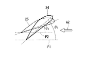
- FIG. 3 shows the inner fin 24 and the outer fin 25 as viewed from the port side.
- the inner fins 24 and the outer fins 25 are arranged with the wing-shaped ventral side down and the dorsal side up.
- the inner fin 24 is disposed with an installation angle ⁇ i with respect to the reference plane P1 including the rotation axis L1 (see FIG. 2).
- the outer fins 25 are arranged with an installation angle ⁇ o with respect to the reference plane P2 including the rotation axis L1 (see FIG. 2). Then, on the port side, the relationship between these installation angles ⁇ i and ⁇ o is as follows. ⁇ i> ⁇ o (1)
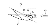
- FIG. 4 shows the inner fin 24 and the outer fin 25 as viewed from the starboard side.
- the inner fins 24 and the outer fins 25 are arranged with the wing-shaped belly side up and the back side down.
- the inner fin 24 is disposed with an installation angle ⁇ i with respect to the reference plane P1 including the rotation axis L1 (see FIG. 2).
- the outer fins 25 are arranged with an installation angle ⁇ o with respect to the reference plane P2 including the rotation axis L1 (see FIG. 2).
- the relationship between these installation angles ⁇ i and ⁇ o is expressed by the following equation. ⁇ i ⁇ o (2)
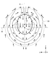
- the upstream side of the propeller 10 becomes a complicated flow field as shown in FIG. 5 due to the shape of the boshing 11 and the upstream side and the surrounding hull shape reaching the boshing 11.
- This figure shows the flow field on the upstream side of the propeller 10 as seen from the rear of the ship as in FIG.
- a horizontal line H and a vertical line V passing through the rotation axis L1 are shown.
- a solid line drawn like a contour line shows an isovelocity line in the direction of the rotation axis L1 (perpendicular to the paper surface), and the flow velocity is smaller on the inner circumference side closer to the rotation axis L1 and higher on the outer circumference side.
- a plurality of arrows indicate the flow direction of the water flow in a plane orthogonal to the rotation axis L1 (in the yz plane).
- the flow from the upper side to the lower side is mainly on the inner peripheral side around the rotation axis L1, and the flow from the lower side to the upper side is mainly along the circumferential direction on the outer peripheral side.
- the region indicated by reference sign S1 is located below the rotation axis L1 and on the outer peripheral side, and is a region where the flow velocity in the direction of the rotation axis L1 is large due to the influence of the flow outside the hull.
- the installation angle ⁇ i of the inner fin 24 and the installation angle ⁇ o of the outer fin 25 is ⁇ i> ⁇ o on the port side.
- the reason is as follows.
- the flow field on the inner peripheral side is mainly the flow from the upper side to the lower side, and is in the direction facing the propeller 10 that rotates from the lower side to the upper side. .
- the installation angle ⁇ i of the inner fin 24 is increased so as to promote the flow from the upper side to the lower side.
- the installation angle ⁇ i is set to be an angle of attack along the inflowing flow. In this case, the angle of attack is set to, for example, 0 ° to 20 ° C., preferably 0 ° to 15 °.
- the flow field on the outer peripheral side is mainly from the bottom to the top, and is in the same direction as the propeller 10 that rotates from the bottom to the top.
- the outer fins 25 have an installation angle that changes the flow downward.
- the installation angle ⁇ o of the outer fin 25 is set smaller than the installation angle ⁇ i of the inner fin 24.
- the inner fin 24 and the outer fin 25 were installed with the wing-shaped ventral side facing downward. Thereby, the flow direction can be effectively changed from the upper side to the lower side using the ventral shape, and the flow field can be further improved.
- the flow field on the inner peripheral side mainly flows from the upper side to the lower side, and is in the same direction as the propeller 10 that rotates from the upper side to the lower side. For this reason, the installation angle ⁇ i is increased so that the inner fin 24 changes the flow upward.
- the flow field on the outer peripheral side is mainly a flow from the lower side to the upper side, and is in a direction facing the propeller 10 rotating from the lower side to the upper side.
- the installation angle ⁇ o of the outer fin 25 is increased so as to promote the flow from the lower side to the upper side.
- the installation angle ⁇ o is set to be an angle of attack along the inflowing flow.
- the angle of attack is set to, for example, 0 ° to 20 ° C., preferably 0 ° to 15 °. From the above, as shown in Expression (2), the installation angle ⁇ o of the outer fin 25 is set larger than the installation angle ⁇ i of the inner fin 24.
- the inner fin 24 and the outer fin 25 were installed with the wing-shaped ventral side facing upward. Thereby, the flow direction can be effectively changed from the lower side to the upper side using the ventral shape, and the flow field can be further improved.
- this embodiment demonstrated on the assumption of the propeller clockwise, this embodiment is applicable also in the case of a propeller counterclockwise. Specifically, what is on the starboard side when the propeller is clockwise corresponds to the starboard side when the propeller is counterclockwise, and what is on the starboard side when the propeller is clockwise corresponds to the port side on the left side of the propeller . The same applies to the following embodiments.
- a corresponding outer fin 25b is provided at a position B1 shifted upward from the extending direction of the inner fin 24b in the middle stage of the port side. That is, the inner end of the outer fin 25 b is fixed to the duct 22 above the position where the outer end of the corresponding inner fin 24 b is fixed to the duct 22. This is because a larger flow velocity in the direction of the rotation axis L1 can be avoided in the upper region, and the effect of improving the flow field by providing the outer fins 25b in this region is greater.
- corresponding outer fins 25c and 25f are provided in the extending direction of the upper inner fin 24c on the port side and the inner fin 24f on the upper side of the starboard. This arrangement is the same as in the first embodiment.
- the installation angles ⁇ i and ⁇ o of the fins 24 and 25 are determined according to the flow field, as in the first embodiment.
- the number of the outer fins 25 is smaller than the number of the inner fins 24, and the number of the respective fins is different.
- the inner fins 24 and the outer fins 25 are positioned appropriately at the inner peripheral side and the outer peripheral side, which have different flow fields. Can be installed. Thereby, the flow field upstream of the propeller is improved on the inner peripheral side and the outer peripheral side, and the propulsion performance can be improved.
- the extending direction in the radial direction of the middle outer fin 25b on the port side and the outer fin 25c on the upper side of the port side is longer than the extending direction in the radial direction of the corresponding inner fins 24b and 24c. It faces upwards.
- the outer fin 25b on the middle side of the port side is fixed to the duct 22 at a position B1 above the extending direction of the corresponding inner fin 24b, and above the horizontal line H that is the extending direction of the corresponding inner fin 24b. It is arranged to face.
- the outer fin 25c at the upper end of the port side is fixed at the same circumferential position as the position where the corresponding inner fin 24c is fixed to the duct 22, while the fixed position with respect to the duct 22 is used as a boundary to the inner fin 24c. On the other hand, it is arranged in a state bent upward.
- the starboard outer fins 25e and 25f are provided in the same extending direction as the corresponding inner fins 243 and 24f, as in the first embodiment.
- the following operational effects can be obtained. Since the extending direction of the outer fins 25b and 25c is directed upward from the extending direction of the corresponding inner fins 24b and 24c, the flow is directed in a direction opposite to the propeller 10 that rotates upward from below on the port side. Can be changed. Thereby, the propeller efficiency can be improved by further improving the flow field above the port side.
- the upper side on the port side means a region above the horizontal line H passing through the rotation axis L1.
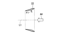
- FIG. 8 shows a longitudinal sectional view of the duct 22.
- the longitudinal section of the duct 22 has a wing shape.
- the cord length direction is provided so as to incline from the upstream side toward the downstream side toward the rotation axis L1. That is, the opening on the downstream side is smaller than the opening on the upstream side of the duct 22.
- the wing-shaped belly side is provided so as to face the inner peripheral side (rotation axis L1 side).
- the duct 22 has a wing-shaped longitudinal section in which the cord length direction is inclined so as to be inclined toward the rotation axis L1 from the upstream side toward the downstream side, the propulsive force is generated by the flow flowing into the duct 22. Obtainable. That is, above the duct 22, the water flow that flows into the inner peripheral side of the duct 22 generates lift F ⁇ b> 1 on the flank side of the wing shape. The component force of the rotational axis L1 of the lift force F1 becomes a propulsive force.
- the cord length below the duct 22 is smaller than the cord length above the duct 22. That is, the opening position on the downstream side of the duct 22 coincides with the upper and lower sides of the duct 22 in the direction of the rotation axis L1, but the opening position on the upstream side of the duct 22 is lower than the upper side of the duct 22. It is located on the downstream side.
- the flow field on the inner peripheral side is directed downward, so that even the wing-shaped duct 22 may cause separation of the flow and obtain a propulsive force. It's hard to be done. Therefore, the cord length below the duct 22 is made shorter than the upper one so as not to become more resistant. Note that the installation angle below the duct 22 may be set different from that above the duct 22 so that the installation angle is less resistant.
- a duct missing portion 22 a in which the duct 22 is partially missing is provided below the duct 22. That is, the duct 22 does not exist between the lower inner fins 24a and 24d. Therefore, the cross-sectional shape of the duct 22 is a C shape having an opening below.
- a partially missing duct portion 22 a is provided below the duct 22 to form a region where the duct 22 is not provided. Thereby, the resistance of the duct 22 in the region where the flow separation and the flow velocity in the direction of the rotation axis L1 are large can be reduced.
- this embodiment can be combined with each embodiment mentioned above.
- FIG. 11 is a diagram showing the duct 22 superimposed on the flow field shown in FIG.
- the duct center C1 is located at a position different from the rotation axis L1, and is provided above the rotation axis L1.
- the cross-sectional shape of the duct 22 is an elliptical shape having a long axis that coincides with the vertical line V.
- the duct center C1 is an elliptical centroid.
- the upper half of the duct 22 is installed in a region that flows from above toward the duct center C1. Thereby, a thrust can be more effectively generated in the duct 22.
- the lower half of the duct 22 has a long axis of the ellipse directed in the direction of the vertical line V, and the right and left walls in FIG. Yes. Further, by directing the short axis of the ellipse in the direction of the horizontal line H, the region of the lower end portion of the duct 22 is shortened to reduce the resistance.
- FIG. 12 shows a modification of FIG.
- the duct center C1 is provided below the rotation axis L1.
- the elliptical shape of the cross section of the duct 22 is provided with a short axis corresponding to the vertical line V, and a long axis is provided along the horizontal line H direction.
- the upper half of the duct 22 is installed in a region that flows from above toward the duct center C1. Thereby, a thrust can be more effectively generated in the duct 22.
- the lower half of the duct 22 is provided so that the water flow is deflected in the left-right direction (horizontal direction) from the downward flow and coincides with the upward flow. Thereby, the resistance of the duct 22 can be reduced.
- the cross-sectional shape of the duct 22 is an ellipse.
- the shape is not limited to this, and a shape in which a plurality of curvatures are combined so as to be in an appropriate position according to the flow field. Also good.
- FIG. 13 shows another modification.
- the duct center C1 is located above and to the right of the rotation axis L1. This corresponds to the case where the flow field on the upstream side of the propeller 10 is shifted by a predetermined angle in the right direction indicated by the arrow A5 about the rotation axis L1 due to the influence of the rotation of the propeller 10. That is, the horizontal line of the flow field is shifted to the position indicated by the symbol H ′, and the vertical line is shifted to the position indicated by the symbol V ′.
- the duct 22 can be installed in an appropriate position according to the flow field.
- this embodiment can be combined with each embodiment mentioned above.
Abstract
The present invention comprises: a duct (22) which is located in front of a propeller of a ship, and is fixed to a bossing (11) side so as to surround the rotational axis (L1) of the propeller; inside fins (24) which have outer ends fixed to the inner peripheral side of the duct (22) and extend radially inward towards the rotational axis (L1); and outside fins (25) which are located in the extension direction of the inside fins (24), and which have inner ends fixed to the outer peripheral side of the duct (22) and extend radially outward. If the rotation of the propeller is clockwise as viewed from the rear of the ship, the attack angle with respect to influent water is formed on the port side, and θi > θo is set where θi is the installation angle of the inside fins (24) with respect to a reference plane including the rotational axis (L1) and θo is the installation angle of the outside fins (25) with respect to the reference plane.
Description
本発明は、プロペラ上流側の流れ場を改善するフィンユニット装置およびこれを備えた船舶に関するものである。
The present invention relates to a fin unit device for improving a flow field upstream of a propeller and a ship equipped with the same.
船舶の推進性能改善のため、プロペラの上流側に、プロペラと逆向きの旋回流れを誘起するフィンユニットを設けることが知られている(特許文献1及び2参照)。
また、特許文献3には、ボッシングに固定された円筒形状の前方ノズルを外部フィンが外方に突出するように設けられた構成が開示されている。さらに、外部フィンと内部フィンとで異なる迎角を有することで、予備渦流を最適化できることが記載されている。 In order to improve the propulsion performance of a ship, it is known to provide a fin unit that induces a swirling flow in the direction opposite to the propeller on the upstream side of the propeller (seePatent Documents 1 and 2).
Patent Document 3 discloses a configuration in which a cylindrical front nozzle fixed to a bossing is provided so that external fins protrude outward. Furthermore, it is described that the preliminary swirl can be optimized by having different angles of attack between the outer fin and the inner fin.
また、特許文献3には、ボッシングに固定された円筒形状の前方ノズルを外部フィンが外方に突出するように設けられた構成が開示されている。さらに、外部フィンと内部フィンとで異なる迎角を有することで、予備渦流を最適化できることが記載されている。 In order to improve the propulsion performance of a ship, it is known to provide a fin unit that induces a swirling flow in the direction opposite to the propeller on the upstream side of the propeller (see
Patent Document 3 discloses a configuration in which a cylindrical front nozzle fixed to a bossing is provided so that external fins protrude outward. Furthermore, it is described that the preliminary swirl can be optimized by having different angles of attack between the outer fin and the inner fin.
しかし、上記特許文献3には、外部フィンと内部フィンの迎角を異ならせると開示されているが、プロペラ上流側の流れ場は複雑で各位置で流れ方向が異なるため、水流の流れとフィン設置角度で決まる迎角は一様に定まるものではない。すなわち、異なる位置にフィンが設置されれば、フィン設置角度が同じでも各フィンの迎角は異なることになる。したがって、特許文献3に開示された異なる迎角でフィンを設置するという事項は、技術的な意味を成さず、具体的な課題解決手段を示していない。
However, Patent Document 3 discloses that the angle of attack between the external fin and the internal fin is different. However, the flow field on the upstream side of the propeller is complicated and the flow direction is different at each position. The angle of attack determined by the installation angle is not fixed uniformly. That is, if fins are installed at different positions, the angle of attack of each fin will be different even if the fin installation angle is the same. Therefore, the matter of disposing fins at different angles of attack disclosed in Patent Document 3 does not make technical sense and does not indicate specific problem solving means.
本発明は、このような事情に鑑みてなされたものであって、プロペラ上流側の流れ場を改善して船舶の推進性能を向上させることができるフィンユニット装置およびこれを備えた船舶を提供することを目的とする。
This invention is made in view of such a situation, Comprising: The fin unit apparatus which can improve the propulsion performance of a ship by improving the flow field of a propeller upstream, and a ship provided with the same are provided. For the purpose.
上記課題を解決するために、本発明のフィンユニット装置およびこれを備えた船舶は以下の手段を採用する。
In order to solve the above problems, the fin unit device of the present invention and a ship equipped with the same employ the following means.
本発明の一態様に係るフィンユニット装置は、プロペラの船舶前方に位置し、該プロペラの回転軸線を囲むようにボッシング側に固定されたダクトと、前記ダクトの内周側に外方端部が固定され、前記回転軸線に向けて半径方向内側に延在する内側フィンと、該内側フィンの延在方向に位置するとともに、前記ダクトの外周側に内方端部が固定され、半径方向外側に延在する外側フィンとを備え、少なくとも一対の前記内側フィン及び前記外側フィンは、前記プロペラが船舶後方から見て右回転の場合には左舷側、または、前記プロペラが船舶後方から見て左回転の場合には右舷側にて、流入する水に対して迎角を形成し、前記回転軸線を含む基準面に対する前記内側フィンの設置角度をθi、前記基準面に対する前記外側フィンの設置角度をθoとした場合に、θi>θoとされている。
A fin unit device according to an aspect of the present invention includes a duct that is located in front of a propeller vessel and is fixed to a boshing side so as to surround a rotation axis of the propeller, and an outer end portion on an inner peripheral side of the duct. An inner fin that is fixed and extends radially inward toward the rotational axis, and is positioned in the extending direction of the inner fin, and an inner end is fixed to the outer peripheral side of the duct, and is radially outward. And at least a pair of the inner fin and the outer fin are on the port side when the propeller is rotated clockwise as viewed from the rear of the ship, or is rotated counterclockwise when the propeller is viewed from the rear of the ship. In this case, on the starboard side, an angle of attack is formed with respect to the inflowing water, the installation angle of the inner fin with respect to the reference plane including the rotation axis is θi, and the installation angle of the outer fin with respect to the reference plane To the case of a θo, there is a θi> θo.
プロペラの船舶前方に位置するダクトに対して固定された内側フィン及び外側フィンによって、プロペラ上流で予旋回を促進させてプロペラ効率を向上させる。
内側フィンと外側フィンとをダクトに固定することとしたので、内側フィンと外側フィンとを異なる設置角度としても、ダクトを介して容易に設置することができる。
プロペラ上流側は、ボッシング等の船体形状によって複雑な流れ場となる。例えば、プロペラ回転軸線に直交する面内では、プロペラ回転軸線を中心とする内周側では上方から下方への流れが主となり、外周側では円周方向に沿って下方から上方への流れが主となる。本発明者等は、この流れ場に着目して、内側フィンと外側フィンとの設置角度を適正化できることを見出した。
具体的には、プロペラ右回転の場合には左舷側(プロペラ左回転の場合には右舷側)にて、流入する水に対して迎角を形成し、回転軸線を含む基準面に対する内側フィンの設置角度をθi、基準面に対する外側フィンの設置角度をθoとした場合に、θi>θoの関係となるようにした。この理由は以下の通りである。
プロペラ右回転の場合に左舷側(プロペラ左回転の場合に右舷側)では、内周側の流れ場は、上方から下方への流れが主となり、下方から上方に回転するプロペラに対向する方向となる。このため、上方から下方への流れを促進するように内側フィンの設置角度θiを大きくすることが好ましい。
一方、外周側の流れ場は、下方から上方への流れが主となり、下方から上方に回転するプロペラと同一方向となる。このため、外側フィンは下向きに流れを変更する設置角度とすることが好ましい。しかし、外周側ではプロペラ回転軸線方向の流速が内周側に比べて大きいため、大きな迎角を得るように外側フィンの設置角度を設定すると外側フィンが流れに対する抵抗となるため好ましくない。したがって、内側フィンの設置角度θiよりも外側フィンの設置角度θoを小さく設定する(θi>θo)。
以上により、内周側及び外周側においてプロペラ上流側の流れ場が改善され、船舶の推進性能を向上させることができる。
なお、内側フィン及び外側フィンを翼形状とする場合には、翼形状の腹側を下方に向けて設置することが好ましい。これにより、腹側形状を利用して効果的に流れ方向を上方から下方に変更することができる。 The inner fin and the outer fin fixed to the duct located in front of the propeller ship promote the pre-turning upstream of the propeller to improve the propeller efficiency.
Since the inner fin and the outer fin are fixed to the duct, the inner fin and the outer fin can be easily installed via the duct even if the inner fin and the outer fin have different installation angles.
The upstream side of the propeller becomes a complicated flow field due to the hull shape such as bossing. For example, in a plane orthogonal to the propeller rotation axis, the flow from the upper side to the lower side is mainly on the inner peripheral side centered on the propeller rotation axis, and the flow from the lower side to the upper side is mainly along the circumferential direction on the outer peripheral side. It becomes. The inventors have found that the installation angle between the inner fin and the outer fin can be optimized by paying attention to this flow field.
Specifically, an angle of attack is formed with respect to the inflowing water on the starboard side in the case of propeller right rotation (starboard side in the case of propeller left rotation), and the inner fin relative to the reference plane including the rotation axis is formed. When the installation angle is θi and the installation angle of the outer fin with respect to the reference plane is θo, the relationship θi> θo is established. The reason is as follows.
On the port side in the case of propeller right rotation (on the starboard side in the case of left rotation of the propeller), the flow field on the inner peripheral side is mainly the flow from the upper side to the lower side, and the direction facing the propeller rotating from the lower side to the upper side. Become. For this reason, it is preferable to increase the installation angle θi of the inner fin so as to promote the flow from the upper side to the lower side.
On the other hand, the flow field on the outer peripheral side is mainly from the bottom to the top, and is in the same direction as the propeller rotating from the bottom to the top. For this reason, it is preferable that the outer fin has an installation angle that changes the flow downward. However, since the flow velocity in the propeller rotation axis direction is larger on the outer peripheral side than on the inner peripheral side, setting the installation angle of the outer fin to obtain a large angle of attack is not preferable because the outer fin becomes resistance to flow. Therefore, the installation angle θo of the outer fin is set smaller than the installation angle θi of the inner fin (θi> θo).
As described above, the flow field on the upstream side of the propeller is improved on the inner peripheral side and the outer peripheral side, and the propulsion performance of the ship can be improved.
In addition, when making an inner fin and an outer fin into a wing | blade shape, it is preferable to install facing the lower side | surface of a wing | blade shape. Thereby, the flow direction can be effectively changed from the upper side to the lower side using the ventral shape.
また、本発明の一態様に係るフィンユニット装置は、プロペラの船舶前方に位置し、該プロペラの回転軸線を囲むようにボッシング側に固定されたダクトと、前記ダクトの内周側に外方端部が固定され、前記回転軸線に向けて半径方向内側に延在する内側フィンと、該内側フィンの延在方向に位置するとともに、前記ダクトの外周側に内方端部が固定され、半径方向外側に延在する外側フィンとを備え、少なくとも一対の前記内側フィン及び前記外側フィンは、前記プロペラが船舶後方から見て右回転の場合には右舷側、または、前記プロペラが船舶後方から見て左回転の場合には左舷側にて、流入する水に対して迎角を形成し、前記回転軸線を含む基準面に対する前記内側フィンの設置角度をθi、前記基準面に対する前記外側フィンの設置角度をθoとした場合に、θi<θoとされている。
The fin unit device according to an aspect of the present invention includes a duct that is positioned in front of the propeller and is fixed to the boshing side so as to surround the rotation axis of the propeller, and an outer end on the inner peripheral side of the duct. The inner fin is fixed in the radial direction toward the rotation axis, the inner fin is positioned in the extending direction of the inner fin, and the inner end is fixed on the outer peripheral side of the duct. And at least a pair of the inner fin and the outer fin when the propeller rotates clockwise when viewed from the rear of the ship, or when the propeller is viewed from the rear of the ship. In the case of left rotation, on the port side, an angle of attack is formed with respect to the inflowing water, the installation angle of the inner fin with respect to the reference plane including the rotation axis is θi, and the outer fin with respect to the reference plane is The 置角 degree when the .theta.o, there is a .theta.i <.theta.o.
プロペラの船舶前方に位置するダクトに対して固定された内側フィン及び外側フィンによって、プロペラ上流で予旋回を促進させてプロペラ効率を向上させる。
内側フィンと外側フィンとをダクトに固定することとしたので、内側フィンと外側フィンとを異なる設置角度としても、ダクトを介して容易に設置することができる。
プロペラ上流側は、ボッシング等の船体形状によって複雑な流れ場となる。例えば、プロペラ回転軸線に直交する面内では、プロペラ回転軸線を中心とする内周側では上方から下方への流れが主となり、外周側では円周方向に沿って下方から上方への流れが主となる。本発明者等は、この流れ場に着目して、内側フィンと外側フィンとの設置角度を適正化できることを見出した。
具体的には、プロペラ右回転の場合には右舷側(プロペラ左回転の場合には左舷側)にて、流入する水に対して迎角を形成し、回転軸線を含む基準面に対する内側フィンの設置角度をθi、基準面に対する外側フィンの設置角度をθoとした場合に、θi<θoの関係となるようにした。
プロペラ右回転の場合に右舷側(プロペラ左回転の場合に左舷側)では、内周側の流れ場は上方から下方への流れが主となり、上方から下方に回転するプロペラと同一方向となる。このため、内側フィンは上向きに流れを変更するように設置角度θiを大きくすることが好ましい。
一方、外周側の流れ場は、下方から上方への流れが主となり、下方から上方に回転するプロペラと対向する方向となる。このため、下方から上方への流れを促進するように外側フィンの設置角度θoを大きくすることが好ましい。したがって、内側フィンの設置角度θiよりも外側フィンの設置角度θoを大きく設定する(θi<θo)。
以上により、内周側及び外周側においてプロペラ上流の流れ場が改善され、推進性能を向上させることができる。
なお、内側フィン及び外側フィンを翼形状とする場合には、翼形状の腹側を上方に向けて設置することが好ましい。これにより、腹側形状を利用して効果的に流れ方向を下方から上方に変更することができる。 The inner fin and the outer fin fixed to the duct located in front of the propeller ship promote the pre-turning upstream of the propeller to improve the propeller efficiency.
Since the inner fin and the outer fin are fixed to the duct, the inner fin and the outer fin can be easily installed via the duct even if the inner fin and the outer fin have different installation angles.
The upstream side of the propeller becomes a complicated flow field due to the hull shape such as bossing. For example, in a plane orthogonal to the propeller rotation axis, the flow from the upper side to the lower side is mainly on the inner peripheral side centered on the propeller rotation axis, and the flow from the lower side to the upper side is mainly along the circumferential direction on the outer peripheral side. It becomes. The inventors have found that the installation angle between the inner fin and the outer fin can be optimized by paying attention to this flow field.
Specifically, in the case of propeller right rotation, the angle of attack is formed on the starboard side (portal side in the case of propeller left rotation) with respect to the inflowing water, and the inner fin relative to the reference plane including the rotation axis is formed. When the installation angle is θi and the installation angle of the outer fin with respect to the reference plane is θo, the relationship θi <θo is established.
On the starboard side in the case of propeller right rotation (on the starboard side in the case of left rotation of the propeller), the flow field on the inner peripheral side mainly flows from the upper side to the lower side, and is in the same direction as the propeller rotating from the upper side to the lower side. For this reason, it is preferable to increase the installation angle θi so that the inner fin changes its flow upward.
On the other hand, the flow field on the outer peripheral side is mainly from the bottom to the top, and is in a direction facing the propeller rotating from the bottom to the top. For this reason, it is preferable to increase the installation angle θo of the outer fin so as to promote the flow from the lower side to the upper side. Therefore, the installation angle θo of the outer fin is set larger than the installation angle θi of the inner fin (θi <θo).
As described above, the flow field upstream of the propeller is improved on the inner peripheral side and the outer peripheral side, and the propulsion performance can be improved.
In addition, when making an inner fin and an outer fin into a wing | blade shape, it is preferable to install facing the upper side of a wing | blade shape. Thereby, the flow direction can be effectively changed from below to above using the ventral shape.
また、本発明の一態様に係るフィンユニット装置は、プロペラの船舶前方に位置し、該プロペラの回転軸線を囲むようにボッシング側に固定されたダクトと、前記ダクトの内周側に外方端部が固定され、前記回転軸線に向けて半径方向内側に延在する内側フィンと、該内側フィンの延在方向とは異なる位置に、前記ダクトの外周側に内方端部が固定され、半径方向外側に延在する外側フィンとを備えている。
The fin unit device according to an aspect of the present invention includes a duct that is positioned in front of the propeller and is fixed to the boshing side so as to surround the rotation axis of the propeller, and an outer end on the inner peripheral side of the duct. The inner fin extending radially inward toward the rotation axis and the inner end fixed to the outer peripheral side of the duct at a position different from the extending direction of the inner fin. And an outer fin extending outward in the direction.
プロペラの船舶前方に位置するダクトに対して固定された内側フィン及び外側フィンによって、プロペラ上流で予旋回を促進させてプロペラ効率を向上させる。
内側フィンと外側フィンとをダクトに固定することとしたので、内側フィンと外側フィンとを異なる設置角度としても、ダクトを介して容易に設置することができる。
プロペラ上流側は、ボッシング等の船体形状によって複雑な流れ場となる。例えば、プロペラ回転軸線に直交する面内では、プロペラ回転軸線を中心とする内周側では上方から下方への流れが主となり、外周側では円周方向に沿って下方から上方への流れが主となる。本発明者等は、この流れ場に着目して、内側フィンと外側フィンとの設置角度を適正化できることを見出した。
具体的には、内側フィンの延在方向とは異なる位置に、外側フィンを設けることとした。流れ場が異なる内周側と外周側とでそれぞれ独立して内側フィン及び外側フィンを適正な位置に設置することができ、内周側及び外周側においてプロペラ上流の流れ場が改善され、推進性能を向上させることができる。
なお、内側フィンと外側フィンの設置角度に関する上述の発明と組み合わせることとしても良い。 The inner fin and the outer fin fixed to the duct located in front of the propeller ship promote the pre-turning upstream of the propeller to improve the propeller efficiency.
Since the inner fin and the outer fin are fixed to the duct, the inner fin and the outer fin can be easily installed via the duct even if the inner fin and the outer fin have different installation angles.
The upstream side of the propeller becomes a complicated flow field due to the hull shape such as bossing. For example, in a plane orthogonal to the propeller rotation axis, the flow from the upper side to the lower side is mainly on the inner peripheral side centered on the propeller rotation axis, and the flow from the lower side to the upper side is mainly along the circumferential direction on the outer peripheral side. It becomes. The inventors have found that the installation angle between the inner fin and the outer fin can be optimized by paying attention to this flow field.
Specifically, the outer fin is provided at a position different from the extending direction of the inner fin. Inner fins and outer fins can be installed at appropriate positions independently on the inner and outer circumferential sides, which have different flow fields, and the flow field upstream of the propeller is improved on the inner and outer circumferential sides. Can be improved.
In addition, it is good also as combining with the above-mentioned invention regarding the installation angle of an inner side fin and an outer side fin.
さらに、本発明の一態様に係るフィンユニット装置では、前記ダクトの下方には、前記外側フィンを設けない。
Furthermore, in the fin unit device according to one aspect of the present invention, the outer fin is not provided below the duct.
ダクトの下方の外周側は、プロペラ回転軸線方向の流速が大きい領域であり、外側フィンが抵抗となってしまうおそれがあるため、ダクトの下方には外側フィンを設けないこととした。このような場合には、内側フィンの枚数よりも外側フィンの枚数の方が少なくなることもある。
ダクトの下方とは、例えば、船舶後方からダクトを見た場合に、プロペラ回転軸線を通る水平線よりも下方の領域を意味する。 The outer peripheral side below the duct is a region where the flow velocity in the direction of the propeller rotation axis is large, and the outer fin may become a resistance. Therefore, the outer fin is not provided below the duct. In such a case, the number of outer fins may be smaller than the number of inner fins.
The lower part of the duct means, for example, a region below a horizontal line passing through the propeller rotation axis when the duct is viewed from the rear of the ship.
さらに、本発明の一態様に係るフィンユニット装置では、前記プロペラが船舶後方から見て右回転の場合には左舷側、または、前記プロペラが船舶後方から見て左回転の場合には右舷側にて、前記外側フィンの前記内方端部は、対応する前記内側フィンよりも上方の位置で前記ダクトに固定されている。
Furthermore, in the fin unit device according to an aspect of the present invention, the propeller is on the starboard side when the propeller is rotated rightward when viewed from the rear of the ship, or the starboard side when the propeller is rotated left when viewed from the rear of the ship. The inner end of the outer fin is fixed to the duct at a position above the corresponding inner fin.
プロペラが船舶後方から見て右回転の場合には左舷側、または、プロペラが船舶後方から見て左回転の場合には右舷側にて、外側フィンの内方端部を、対応する内側フィンよりも上方の位置でダクトに固定することとした。これは、プロペラ右回転の場合には左舷側(プロペラ左回転の場合には右舷側)では、上方の領域ほどプロペラ回転軸線方向の大きな流速を避けることができるので、外側フィンを設けることによる流れ場改善の効果が大きいからである。
When the propeller is rotating clockwise when viewed from the rear of the ship, or on the starboard side when the propeller is rotating left when viewed from the rear of the ship, the inner end of the outer fin is connected to the corresponding inner fin. Was fixed to the duct at an upper position. This is because, on the port side in the case of propeller right rotation (on the starboard side in the case of propeller left rotation), a larger flow velocity in the direction of the propeller rotation axis can be avoided in the upper region. This is because the effect of field improvement is great.
また、本発明の一態様に係るフィンユニット装置は、プロペラの船舶前方に位置し、該プロペラの回転軸線を囲むようにボッシング側に固定されたダクトと、前記ダクトの内周側に外方端部が固定され、前記回転軸線に向けて半径方向内側に延在する内側フィンと、該内側フィンの延在方向に位置するとともに、前記ダクトの外周側に内方端部が固定され、半径方向外側に延在する外側フィンとを備え、前記プロペラが船舶後方から見て右回転の場合には左舷側の上方、または、前記プロペラが船舶後方から見て左回転の場合には右舷側の上方にて、前記外側フィンの延在方向が、対応する前記内側フィンの延在方向よりも上方に向いている。
The fin unit device according to an aspect of the present invention includes a duct that is positioned in front of the propeller and is fixed to the boshing side so as to surround the rotation axis of the propeller, and an outer end on the inner peripheral side of the duct. The inner fin is fixed in the radial direction toward the rotation axis, the inner fin is positioned in the extending direction of the inner fin, and the inner end is fixed on the outer peripheral side of the duct. An outer fin extending outwardly, and when the propeller rotates clockwise when viewed from the rear of the ship, or when the propeller rotates left when viewed from the rear of the ship, the upper side of the starboard side Then, the extending direction of the outer fins is directed upward from the extending direction of the corresponding inner fin.
プロペラの船舶前方に位置するダクトに対して固定された内側フィン及び外側フィンによって、プロペラ上流で予旋回を促進させてプロペラ効率を向上させる。
内側フィンと外側フィンとをダクトに固定することとしたので、内側フィンと外側フィンとを異なる設置角度としても、ダクトを介して容易に設置することができる。
プロペラ上流側は、ボッシング等の船体形状によって複雑な流れ場となる。例えば、プロペラ回転軸線に直交する面内では、プロペラ回転軸線を中心とする内周側では上方から下方への流れが主となり、外周側では円周方向に沿って下方から上方への流れが主となる。本発明者等は、この流れ場に着目して、内側フィンと外側フィンとの設置角度を適正化できることを見出した。
具体的には、プロペラ右回転の場合には左舷側の上方(プロペラ左回転の場合には右舷側の上方)では、外側フィンの半径方向における延在方向を、対応する内側フィンの半径方向における延在方向よりも上方に向けるようにした。これにより、下方から上方に回転するプロペラに対向する方向に流れを変更することができる。
なお、プロペラ右回転の場合には左舷側の上方(プロペラ左回転の場合には右舷側の上方)とは、例えば、船舶後方から見た場合に、プロペラ回転軸線を通る水平線よりも上方の領域を意味する。
また、内側フィンと外側フィンの設置角度に関する上述の発明や、内側フィンと外側フィンとのダクトに対する設置位置を異ならせた上述の発明と組み合わせることとしても良い。 The inner fin and the outer fin fixed to the duct located in front of the propeller ship promote the pre-turning upstream of the propeller to improve the propeller efficiency.
Since the inner fin and the outer fin are fixed to the duct, the inner fin and the outer fin can be easily installed via the duct even if the inner fin and the outer fin have different installation angles.
The upstream side of the propeller becomes a complicated flow field due to the hull shape such as bossing. For example, in a plane orthogonal to the propeller rotation axis, the flow from the upper side to the lower side is mainly on the inner peripheral side centered on the propeller rotation axis, and the flow from the lower side to the upper side is mainly along the circumferential direction on the outer peripheral side. It becomes. The inventors have found that the installation angle between the inner fin and the outer fin can be optimized by paying attention to this flow field.
Specifically, in the case of propeller clockwise rotation, on the port side (in the case of propeller counterclockwise, on the starboard side), the extending direction in the radial direction of the outer fin is set in the radial direction of the corresponding inner fin. It was made to face upwards from the extending direction. Thereby, a flow can be changed in the direction which opposes the propeller which rotates upwards from the downward direction.
In the case of propeller right rotation, the port side upper side (in the case of propeller left rotation, on the starboard side) is, for example, an area above the horizontal line passing through the propeller rotation axis when viewed from the rear of the ship. Means.
Moreover, it is good also as combining the above-mentioned invention regarding the installation angle of an inner fin and an outer fin, and the above-mentioned invention which made the installation position with respect to the duct of an inner fin and an outer fin different.
さらに、本発明の一態様に係るフィンユニット装置では、前記ダクトは、上流側から下流側に向けて前記回転軸線側に傾斜するようにコード長方向が設けられた翼形状の縦断面を有する。
Furthermore, in the fin unit device according to one aspect of the present invention, the duct has a wing-shaped longitudinal section in which a cord length direction is provided so as to incline from the upstream side toward the downstream side toward the rotation axis.
ダクトを、上流側から下流側に向けてプロペラ回転軸線側に傾斜するようにコード長方向が設けられた翼形状の縦断面を有するようにしたので、ダクトに流入する流れによって推進力を得ることができる。
Since the duct has a wing-shaped longitudinal section with the cord length direction inclined to the propeller rotation axis side from the upstream side to the downstream side, the propulsive force is obtained by the flow flowing into the duct Can do.
さらに、本発明の一態様に係るフィンユニット装置では、前記ダクトの下方における前記コード長が、該ダクトの上方における前記コード長よりも小さい。
Furthermore, in the fin unit device according to one aspect of the present invention, the cord length below the duct is smaller than the cord length above the duct.
ダクトの下方では、内周側における流れ場が下方に向かうようになっているので、翼形状のダクトであっても流れの剥離が生じ易く推進力が得られにくい。そこで、ダクトの下方のコード長を上方よりも短くして、より抵抗とならないようにした。なお、ダクト下方の設置角度をダクト上方と異ならせて、より抵抗とならないように設置角度を設定してもよい。
ダクトの下方とは、例えば、船舶後方からダクトを見た場合に、プロペラ回転軸線を通る水平線よりも下方の領域を意味する。 Below the duct, the flow field on the inner peripheral side is directed downward, so that even in the case of a wing-shaped duct, flow separation is likely to occur and it is difficult to obtain a driving force. Therefore, the cord length below the duct is made shorter than the upper one so as not to become more resistant. Note that the installation angle below the duct may be set different from that above the duct so that the installation angle does not become more resistance.
The lower part of the duct means, for example, a region below a horizontal line passing through the propeller rotation axis when the duct is viewed from the rear of the ship.
さらに、本発明の一態様に係るフィンユニット装置では、前記ダクトの下方には、該ダクトを部分的に欠損させたダクト欠損部が設けられている。
Furthermore, in the fin unit device according to one aspect of the present invention, a duct missing portion in which the duct is partially missing is provided below the duct.
ダクトの下方に、部分的に欠損させたダクト欠損部を設け、ダクトを設けない領域を形成することとした。これにより、流れの剥離やプロペラ回転軸線方向の流速が大きい領域でのダクトの抵抗を低減することができる。
The lower part of the duct was provided with a part of the duct missing part that was partly missing to form a region where no duct was provided. Thereby, the resistance of the duct in the region where the flow separation and the flow velocity in the direction of the propeller rotation axis are large can be reduced.
さらに、本発明の一態様に係るフィンユニット装置では、前記ダクトを船体後方から見た場合の中心位置は、前記回転軸線と異なる。
Furthermore, in the fin unit device according to one aspect of the present invention, the center position when the duct is viewed from the rear of the hull is different from the rotation axis.
プロペラ上流側は、ボッシング等の船体形状によって複雑な流れ場となる。このため、ダクトは、上述のように推力を発生する領域もある一方で、ダクト自身が抵抗となる領域もある。そこで、ダクトの中心位置をプロペラ回転軸線と異なる位置に設置することで、ダクトの性能を効果的に発揮させることができる。
例えば、ダクト上方のように推力を発生できる位置では流れに対して推力を有効に発生できる位置にダクトを位置させるとともに、ダクト下方のように推力を発生させ難い位置では可及的に流線に沿うようにダクトを位置させて抵抗を低減するようにする。この場合、ダクトの横断面形状は、円形に限らず、楕円形や長円形、あるいは一部を切り欠いた形状としても良い。円形でない場合の形状における中心位置とは、図心を意味する。
また、プロペラの回転による影響でプロペラ上流側の流れ場が変化する場合には、これに応じてダクトの中心位置を設定する。例えば、ダクトの中心位置を、プロペラ回転軸線を通る鉛直線上からプロペラの回転方向にずらして設定しても良い。 The upstream side of the propeller becomes a complicated flow field due to the hull shape such as bossing. For this reason, the duct has a region where thrust is generated as described above, and there is also a region where the duct itself becomes a resistance. Therefore, by installing the center position of the duct at a position different from the propeller rotation axis, the performance of the duct can be effectively exhibited.
For example, at a position where thrust can be generated, such as above the duct, the duct is positioned at a position where thrust can be effectively generated with respect to the flow. The duct is positioned along the line to reduce the resistance. In this case, the cross-sectional shape of the duct is not limited to a circle, but may be an ellipse, an oval, or a shape with a part cut away. The center position in the shape when it is not circular means the centroid.
When the flow field on the upstream side of the propeller changes due to the influence of the rotation of the propeller, the center position of the duct is set accordingly. For example, the center position of the duct may be set so as to be shifted from the vertical line passing through the propeller rotation axis in the propeller rotation direction.
また、本発明の一態様に係る船舶は、回転軸線回りに回転するプロペラと、該プロペラを回転可能に支持するとともに、該プロペラの船舶前方に設けられたボッシングと、該ボッシングに設けられた上記いずれかに記載のフィンユニット装置とを備えている。
In addition, a ship according to an aspect of the present invention includes a propeller that rotates about a rotation axis, the propeller rotatably supported, a boshing provided in front of the propeller ship, and the above-described boshing. One of the fin unit devices described above is provided.
プロペラ上流側の流れ場に応じて内側フィン及び外側フィンを適正に設置することとしたので、プロペラ上流側の流れ場を改善して船舶の推進性能を向上させることができる。
Since the inner and outer fins are appropriately installed according to the flow field upstream of the propeller, the propulsion performance of the ship can be improved by improving the flow field upstream of the propeller.
[第1実施形態]
図1には、本発明の第1実施形態に係る船舶1の船尾部分が示されている。船尾部分には、ボッシング11と、船尾オーバーハング部12が設けられている。ボッシング11は、プロペラの上流側に位置し、推進用のプロペラ10が回転軸線L1まわりに回転可能なようにプロペラ10を回転可能に支持する。船尾オーバーハング部12は、プロペラ10の上方位置に設けられている。 [First Embodiment]
FIG. 1 shows a stern portion of aship 1 according to the first embodiment of the present invention. A stern portion is provided with a bossing 11 and a stern overhang portion 12. The bossing 11 is located on the upstream side of the propeller, and rotatably supports the propeller 10 so that the propeller 10 for propulsion can rotate about the rotation axis L1. The stern overhang portion 12 is provided above the propeller 10.
図1には、本発明の第1実施形態に係る船舶1の船尾部分が示されている。船尾部分には、ボッシング11と、船尾オーバーハング部12が設けられている。ボッシング11は、プロペラの上流側に位置し、推進用のプロペラ10が回転軸線L1まわりに回転可能なようにプロペラ10を回転可能に支持する。船尾オーバーハング部12は、プロペラ10の上方位置に設けられている。 [First Embodiment]
FIG. 1 shows a stern portion of a
ボッシング11には、フィンユニット装置20が取り付けられている。フィンユニット装置20は、前進時のプロペラ10の回転方向と逆向きの旋回流を発生させて、プロペラ効率を向上させる。
The fin unit device 20 is attached to the bossing 11. The fin unit device 20 generates a swirling flow in the direction opposite to the rotation direction of the propeller 10 at the time of forward movement, thereby improving the propeller efficiency.
図2には、フィンユニット装置20を後方から見た正面図を示している。図2の右下に座標軸が示されているように、船舶の進行方向をx軸、x軸に直交する水平方向をy軸、x軸に直交する鉛直方向をz軸とされている(以下同じ)。
FIG. 2 shows a front view of the fin unit device 20 as viewed from the rear. As shown in the coordinate axis at the lower right of FIG. 2, the traveling direction of the ship is the x axis, the horizontal direction orthogonal to the x axis is the y axis, and the vertical direction orthogonal to the x axis is the z axis (hereinafter referred to as “x axis”). the same).
フィンユニット装置20は、ダクト22と、ダクト22の内周側に位置する内側フィン24と、ダクト22の外周側に位置する外側フィン25とを備えている。
The fin unit device 20 includes a duct 22, an inner fin 24 positioned on the inner peripheral side of the duct 22, and an outer fin 25 positioned on the outer peripheral side of the duct 22.
ダクト22は、円筒形状とされており、ダクト22の中心軸線はプロペラ10の回転軸線L1と一致している。ダクト22の半径は、プロペラ10の半径をRとした場合、0.3R以上0.9R以下とされている。
The duct 22 has a cylindrical shape, and the central axis of the duct 22 coincides with the rotation axis L1 of the propeller 10. The radius of the duct 22 is 0.3R or more and 0.9R or less, where R is the radius of the propeller 10.
内側フィン24は、内方端部がボッシング11に固定され、外方端部がダクト22の内周面に固定されている。内側フィン24は、回転軸線L1を中心とする半径方向に延在している。図3及び図4に示すように、内側フィン24の断面は翼形状とされており、翼先端が船舶前方側を向き、翼後端が船舶後方を向くように配置されている。
The inner fin 24 has an inner end fixed to the boshing 11 and an outer end fixed to the inner peripheral surface of the duct 22. The inner fin 24 extends in the radial direction around the rotation axis L1. As shown in FIG. 3 and FIG. 4, the cross section of the inner fin 24 has a wing shape, and is disposed so that the wing tip faces the ship front side and the wing rear end faces the ship rear.
外側フィン25は、図2に示されているように、内方端部がダクト22の外周面に固定され、外方端部が自由端とされている。外側フィン25の外方端部は、プロペラ10の外周直径D1と同等の位置に配置されている。外側フィン25は、対応する内側フィン24の延在方向に一致するように、回転軸線L1を中心とする半径方向に延在している。図3及び図4に示すように、外側フィン25の断面は翼形状とされており、翼先端が船舶前方側を向き、翼後端が船舶後方を向くように配置されている。
As shown in FIG. 2, the outer fin 25 has an inner end fixed to the outer peripheral surface of the duct 22 and an outer end being a free end. The outer end portion of the outer fin 25 is disposed at a position equivalent to the outer peripheral diameter D <b> 1 of the propeller 10. The outer fins 25 extend in the radial direction about the rotation axis L <b> 1 so as to coincide with the extending direction of the corresponding inner fin 24. As shown in FIGS. 3 and 4, the cross section of the outer fin 25 has a wing shape, and is arranged so that the wing tip faces the ship front side and the wing rear end faces the ship rear.
同一の半径方向に延在する内側フィン24及び外側フィン25の対は、本実施形態では6対設けられている。具体的には、左舷側に、下段のフィン24a,25a、中段のフィン24b,25b及び上段のフィン24c,25cの3対が設けられ、右舷側に、下段のフィン24d,25d、中段のフィン24e,25e及び上段のフィン24f,25fの3対が設けられている。各対のフィン24,25は、回転軸線L1を通る鉛直線Vに対して左右対称に設けられているが、適宜その位置を変更することができる。
中段のフィン24b,25b,24e,25eは、水平線H方向に延在している。下段のフィン24a,25a,24d,25d及び上段のフィン24c,25c,24f,25fは、中段のフィン24b,25b,24e,25eの延在方向(水平線H方向)に対して対象に振り分けられて配置されている。ただし、本発明はこれらのフィン配置に限定されるものではない。 In the present embodiment, six pairs ofinner fins 24 and outer fins 25 extending in the same radial direction are provided. Specifically, three pairs of lower fins 24a and 25a, middle fins 24b and 25b, and upper fins 24c and 25c are provided on the port side, and lower fins 24d and 25d and middle fins are provided on the starboard side. Three pairs of 24e and 25e and upper fins 24f and 25f are provided. The pairs of fins 24 and 25 are provided symmetrically with respect to the vertical line V passing through the rotation axis L1, but the positions thereof can be changed as appropriate.
The middle fins 24b, 25b, 24e, and 25e extend in the horizontal line H direction. The lower fins 24a, 25a, 24d, and 25d and the upper fins 24c, 25c, 24f, and 25f are distributed to the target in the extending direction (horizontal line H direction) of the middle fins 24b, 25b, 24e, and 25e. Has been placed. However, the present invention is not limited to these fin arrangements.
中段のフィン24b,25b,24e,25eは、水平線H方向に延在している。下段のフィン24a,25a,24d,25d及び上段のフィン24c,25c,24f,25fは、中段のフィン24b,25b,24e,25eの延在方向(水平線H方向)に対して対象に振り分けられて配置されている。ただし、本発明はこれらのフィン配置に限定されるものではない。 In the present embodiment, six pairs of
The
上述のように、内側フィン24と外側フィン25とをそれぞれダクト22に固定することとしたので、後述するように内側フィン24と外側フィン25とを異なる設置角度としても、ダクト22を介して容易に設置することができるようになっている。
As described above, since the inner fin 24 and the outer fin 25 are respectively fixed to the duct 22, the inner fin 24 and the outer fin 25 can be easily installed via the duct 22 even when the inner fin 24 and the outer fin 25 have different installation angles as will be described later. It can be installed in.
なお、プロペラ10は、図2に矢印A1で示すように、船舶後方から見た場合に右回りに回転する。
The propeller 10 rotates clockwise as viewed from the rear of the ship, as indicated by an arrow A1 in FIG.
図3には、左舷側から見た内側フィン24及び外側フィン25が示されている。同図において、矢印A2で示すように、水流は右から左に流れる。内側フィン24及び外側フィン25は、翼形状の腹側を下、背側を上にして配置されている。内側フィン24は、回転軸線L1(図2参照)を含む基準面P1に対して、設置角度θiを有して配置されている。外側フィン25は、回転軸線L1(図2参照)を含む基準面P2に対して、設置角度θoを有して配置されている。そして、左舷側において、これら設置角度θi,θoの関係は下式とされる。
θi>θo ・・・(1) FIG. 3 shows theinner fin 24 and the outer fin 25 as viewed from the port side. In the same figure, as shown by arrow A2, the water flow flows from right to left. The inner fins 24 and the outer fins 25 are arranged with the wing-shaped ventral side down and the dorsal side up. The inner fin 24 is disposed with an installation angle θi with respect to the reference plane P1 including the rotation axis L1 (see FIG. 2). The outer fins 25 are arranged with an installation angle θo with respect to the reference plane P2 including the rotation axis L1 (see FIG. 2). Then, on the port side, the relationship between these installation angles θi and θo is as follows.
θi> θo (1)
θi>θo ・・・(1) FIG. 3 shows the
θi> θo (1)
図4には、右舷側から見た内側フィン24及び外側フィン25が示されている。同図において、矢印A3で示すように、水流は右から左に流れる。内側フィン24及び外側フィン25は、翼形状の腹側を上、背側を下にして配置されている。内側フィン24は、回転軸線L1(図2参照)を含む基準面P1に対して、設置角度θiを有して配置されている。外側フィン25は、回転軸線L1(図2参照)を含む基準面P2に対して、設置角度θoを有して配置されている。そして、右舷側において、これら設置角度θi,θoの関係は、下式とされる。
θi<θo ・・・(2) FIG. 4 shows theinner fin 24 and the outer fin 25 as viewed from the starboard side. In the figure, as indicated by an arrow A3, the water flow flows from right to left. The inner fins 24 and the outer fins 25 are arranged with the wing-shaped belly side up and the back side down. The inner fin 24 is disposed with an installation angle θi with respect to the reference plane P1 including the rotation axis L1 (see FIG. 2). The outer fins 25 are arranged with an installation angle θo with respect to the reference plane P2 including the rotation axis L1 (see FIG. 2). And on the starboard side, the relationship between these installation angles θi and θo is expressed by the following equation.
θi <θo (2)
θi<θo ・・・(2) FIG. 4 shows the
θi <θo (2)
上記構成の本実施形態の作用効果を以下に説明する。
プロペラ10の上流側は、ボッシング11の形状や、ボッシング11に至る上流側および周囲の船体形状によって、図5に示すように複雑な流れ場となる。同図は、図2と同様に船舶後方から見たプロペラ10の上流側の流れ場を示している。同図において、回転軸線L1を通る水平線H及び鉛直線Vが示されている。等高線のように描かれた実線は、回転軸線L1方向(紙面垂直方向)の等流速線を示し、回転軸線L1に近い内周側ほど流速が小さく、外周側ほど流速が高い。複数の矢印は、回転軸線L1に直交する面内(y-z面内)における水流の流れ方向を示している。 The effects of this embodiment having the above-described configuration will be described below.
The upstream side of the propeller 10 becomes a complicated flow field as shown in FIG. 5 due to the shape of theboshing 11 and the upstream side and the surrounding hull shape reaching the boshing 11. This figure shows the flow field on the upstream side of the propeller 10 as seen from the rear of the ship as in FIG. In the figure, a horizontal line H and a vertical line V passing through the rotation axis L1 are shown. A solid line drawn like a contour line shows an isovelocity line in the direction of the rotation axis L1 (perpendicular to the paper surface), and the flow velocity is smaller on the inner circumference side closer to the rotation axis L1 and higher on the outer circumference side. A plurality of arrows indicate the flow direction of the water flow in a plane orthogonal to the rotation axis L1 (in the yz plane).
プロペラ10の上流側は、ボッシング11の形状や、ボッシング11に至る上流側および周囲の船体形状によって、図5に示すように複雑な流れ場となる。同図は、図2と同様に船舶後方から見たプロペラ10の上流側の流れ場を示している。同図において、回転軸線L1を通る水平線H及び鉛直線Vが示されている。等高線のように描かれた実線は、回転軸線L1方向(紙面垂直方向)の等流速線を示し、回転軸線L1に近い内周側ほど流速が小さく、外周側ほど流速が高い。複数の矢印は、回転軸線L1に直交する面内(y-z面内)における水流の流れ方向を示している。 The effects of this embodiment having the above-described configuration will be described below.
The upstream side of the propeller 10 becomes a complicated flow field as shown in FIG. 5 due to the shape of the
同図から分かるように、回転軸線L1を中心とする内周側では上方から下方への流れが主となり、外周側では円周方向に沿って下方から上方への流れが主となる。また、符号S1で示した領域は、回転軸線L1の下方でかつ外周側に位置し、船体外方の流れの影響によって回転軸線L1方向の流速が大きい領域である。
As can be seen from the figure, the flow from the upper side to the lower side is mainly on the inner peripheral side around the rotation axis L1, and the flow from the lower side to the upper side is mainly along the circumferential direction on the outer peripheral side. Further, the region indicated by reference sign S1 is located below the rotation axis L1 and on the outer peripheral side, and is a region where the flow velocity in the direction of the rotation axis L1 is large due to the influence of the flow outside the hull.
上式(1)で示したように、プロペラ右回転の場合には左舷側にて、内側フィン24の設置角度θi及び外側フィン25の設置角度θoの関係を、θi>θoとした。この理由は以下の通りである。
プロペラ右回転の場合に左舷側では、内周側の流れ場は、図5に示したように、上方から下方への流れが主となり、下方から上方に回転するプロペラ10に対向する方向となる。このため、上方から下方への流れを促進するように内側フィン24の設置角度θiを大きくする。設置角度θiは、流入する流れに沿う迎角となるように設定され、この場合、迎角は例えば0°以上20℃以下、好ましくは0°以上15°以下に設定される。 As shown in the above equation (1), in the case of propeller clockwise rotation, the relationship between the installation angle θi of theinner fin 24 and the installation angle θo of the outer fin 25 is θi> θo on the port side. The reason is as follows.
In the case of propeller right rotation, on the port side, as shown in FIG. 5, the flow field on the inner peripheral side is mainly the flow from the upper side to the lower side, and is in the direction facing the propeller 10 that rotates from the lower side to the upper side. . For this reason, the installation angle θi of theinner fin 24 is increased so as to promote the flow from the upper side to the lower side. The installation angle θi is set to be an angle of attack along the inflowing flow. In this case, the angle of attack is set to, for example, 0 ° to 20 ° C., preferably 0 ° to 15 °.
プロペラ右回転の場合に左舷側では、内周側の流れ場は、図5に示したように、上方から下方への流れが主となり、下方から上方に回転するプロペラ10に対向する方向となる。このため、上方から下方への流れを促進するように内側フィン24の設置角度θiを大きくする。設置角度θiは、流入する流れに沿う迎角となるように設定され、この場合、迎角は例えば0°以上20℃以下、好ましくは0°以上15°以下に設定される。 As shown in the above equation (1), in the case of propeller clockwise rotation, the relationship between the installation angle θi of the
In the case of propeller right rotation, on the port side, as shown in FIG. 5, the flow field on the inner peripheral side is mainly the flow from the upper side to the lower side, and is in the direction facing the propeller 10 that rotates from the lower side to the upper side. . For this reason, the installation angle θi of the
一方、外周側の流れ場は、下方から上方への流れが主となり、下方から上方に回転するプロペラ10と同一方向となる。このため、外側フィン25は下向きに流れを変更する設置角度とすることが好ましい。しかし、外周側ではプロペラ10の回転軸線L1方向の流速が内周側に比べて大きいため、大きな迎角を得るように外側フィン25の設置角度θoを設定すると外側フィン25が流れに対する抵抗となるため好ましくない。したがって、式(1)に示したように、内側フィン24の設置角度θiよりも外側フィン25の設置角度θoを小さく設定する。
以上により、内周側及び外周側においてプロペラ10の上流側の流れ場が改善され、船舶1の推進性能を向上させることができる。 On the other hand, the flow field on the outer peripheral side is mainly from the bottom to the top, and is in the same direction as the propeller 10 that rotates from the bottom to the top. For this reason, it is preferable that theouter fins 25 have an installation angle that changes the flow downward. However, since the flow velocity in the direction of the rotation axis L1 of the propeller 10 is larger on the outer peripheral side than on the inner peripheral side, the outer fin 25 becomes resistance to flow if the installation angle θo of the outer fin 25 is set so as to obtain a large angle of attack. Therefore, it is not preferable. Therefore, as shown in Expression (1), the installation angle θo of the outer fin 25 is set smaller than the installation angle θi of the inner fin 24.
As described above, the flow field on the upstream side of the propeller 10 is improved on the inner peripheral side and the outer peripheral side, and the propulsion performance of theship 1 can be improved.
以上により、内周側及び外周側においてプロペラ10の上流側の流れ場が改善され、船舶1の推進性能を向上させることができる。 On the other hand, the flow field on the outer peripheral side is mainly from the bottom to the top, and is in the same direction as the propeller 10 that rotates from the bottom to the top. For this reason, it is preferable that the
As described above, the flow field on the upstream side of the propeller 10 is improved on the inner peripheral side and the outer peripheral side, and the propulsion performance of the
内側フィン24及び外側フィン25について、翼形状の腹側を下方に向けて設置することとした。これにより、腹側形状を利用して効果的に流れ方向を上方から下方に変更することができ、更に流れ場を改善することができる。
The inner fin 24 and the outer fin 25 were installed with the wing-shaped ventral side facing downward. Thereby, the flow direction can be effectively changed from the upper side to the lower side using the ventral shape, and the flow field can be further improved.
また、上式(2)で示したように、プロペラ10が右回転の場合には右舷側にて、内側フィン24の設置角度θi及び外側フィン25の設置角度θoの関係を、θi<θoとした。この理由は以下の通りである。
図5に示したように、内周側の流れ場は上方から下方への流れが主となり、上方から下方に回転するプロペラ10と同一方向となる。このため、内側フィン24は上向きに流れを変更するように設置角度θiを大きくする。
一方、外周側の流れ場は、下方から上方への流れが主となり、下方から上方に回転するプロペラ10と対向する方向となる。このため、下方から上方への流れを促進するように外側フィン25の設置角度θoを大きくする。設置角度θoは、流入する流れに沿う迎角となるように設定され、この場合、迎角は例えば0°以上20℃以下、好ましくは0°以上15°以下に設定される。
以上から、式(2)に示したように、内側フィン24の設置角度θiよりも外側フィン25の設置角度θoを大きく設定する。 Further, as shown in the above equation (2), when the propeller 10 rotates clockwise, the relationship between the installation angle θi of theinner fin 24 and the installation angle θo of the outer fin 25 is expressed as θi <θo on the starboard side. did. The reason is as follows.
As shown in FIG. 5, the flow field on the inner peripheral side mainly flows from the upper side to the lower side, and is in the same direction as the propeller 10 that rotates from the upper side to the lower side. For this reason, the installation angle θi is increased so that theinner fin 24 changes the flow upward.
On the other hand, the flow field on the outer peripheral side is mainly a flow from the lower side to the upper side, and is in a direction facing the propeller 10 rotating from the lower side to the upper side. For this reason, the installation angle θo of theouter fin 25 is increased so as to promote the flow from the lower side to the upper side. The installation angle θo is set to be an angle of attack along the inflowing flow. In this case, the angle of attack is set to, for example, 0 ° to 20 ° C., preferably 0 ° to 15 °.
From the above, as shown in Expression (2), the installation angle θo of theouter fin 25 is set larger than the installation angle θi of the inner fin 24.
図5に示したように、内周側の流れ場は上方から下方への流れが主となり、上方から下方に回転するプロペラ10と同一方向となる。このため、内側フィン24は上向きに流れを変更するように設置角度θiを大きくする。
一方、外周側の流れ場は、下方から上方への流れが主となり、下方から上方に回転するプロペラ10と対向する方向となる。このため、下方から上方への流れを促進するように外側フィン25の設置角度θoを大きくする。設置角度θoは、流入する流れに沿う迎角となるように設定され、この場合、迎角は例えば0°以上20℃以下、好ましくは0°以上15°以下に設定される。
以上から、式(2)に示したように、内側フィン24の設置角度θiよりも外側フィン25の設置角度θoを大きく設定する。 Further, as shown in the above equation (2), when the propeller 10 rotates clockwise, the relationship between the installation angle θi of the
As shown in FIG. 5, the flow field on the inner peripheral side mainly flows from the upper side to the lower side, and is in the same direction as the propeller 10 that rotates from the upper side to the lower side. For this reason, the installation angle θi is increased so that the
On the other hand, the flow field on the outer peripheral side is mainly a flow from the lower side to the upper side, and is in a direction facing the propeller 10 rotating from the lower side to the upper side. For this reason, the installation angle θo of the
From the above, as shown in Expression (2), the installation angle θo of the
内側フィン24及び外側フィン25について、翼形状の腹側を上方に向けて設置することとした。これにより、腹側形状を利用して効果的に流れ方向を下方から上方に変更することができ、更に流れ場を改善することができる。
The inner fin 24 and the outer fin 25 were installed with the wing-shaped ventral side facing upward. Thereby, the flow direction can be effectively changed from the lower side to the upper side using the ventral shape, and the flow field can be further improved.
なお、本実施形態では、プロペラ右回りを前提として説明したが、プロペラ左回りの場合にも本実施形態を適用することができる。具体的には、プロペラ右回りの場合に左舷側としていたものがプロペラ左回りの場合の右舷側に対応し、プロペラ右回りの場合に右舷側としていたものがプロペラ左回りの左舷側に対応する。これについては、以下の各実施形態でも同様である。
In addition, although this embodiment demonstrated on the assumption of the propeller clockwise, this embodiment is applicable also in the case of a propeller counterclockwise. Specifically, what is on the starboard side when the propeller is clockwise corresponds to the starboard side when the propeller is counterclockwise, and what is on the starboard side when the propeller is clockwise corresponds to the port side on the left side of the propeller . The same applies to the following embodiments.
[第2実施形態]
次に、本発明の第2実施形態について、図6を用いて説明する。
本実施形態は、第1実施形態に対して、内側フィン24と外側フィン25の配置が異なり、その他は同様である。したがって、以下では相違点のみを説明し、同一の構成については同一符号を用いて説明を省略する。 [Second Embodiment]
Next, a second embodiment of the present invention will be described with reference to FIG.
The present embodiment is different from the first embodiment in the arrangement of theinner fins 24 and the outer fins 25, and is otherwise the same. Accordingly, only the differences will be described below, and the same components are denoted by the same reference numerals and description thereof is omitted.
次に、本発明の第2実施形態について、図6を用いて説明する。
本実施形態は、第1実施形態に対して、内側フィン24と外側フィン25の配置が異なり、その他は同様である。したがって、以下では相違点のみを説明し、同一の構成については同一符号を用いて説明を省略する。 [Second Embodiment]
Next, a second embodiment of the present invention will be described with reference to FIG.
The present embodiment is different from the first embodiment in the arrangement of the
図6に示すように、内側フィン24の延在方向に一致する位置に、対応する外側フィン25が設けられていない対が存在する。
As shown in FIG. 6, there is a pair in which the corresponding outer fin 25 is not provided at a position corresponding to the extending direction of the inner fin 24.
具体的には、左舷の下段の内側フィン24a及び右舷の下段の内側フィン24dの延在方向には対応する外側フィン25が存在しない。これにより、回転軸線L1方向の流速が大きい下方でかつ外周側の位置に外側フィン25を設けないことで、抵抗となることを回避している。このように、ダクト22の下方、すなわち回転軸線L1を通る水平線Hよりも下方の領域に外側フィン25を設けないことが好ましい。
Specifically, there is no corresponding outer fin 25 in the extending direction of the lower inner fin 24a and the lower inner fin 24d of the starboard. Thereby, it is avoided that it becomes resistance by not providing the outer fin 25 in the position where the flow velocity in the direction of the rotation axis L1 is large and on the outer peripheral side. Thus, it is preferable not to provide the outer fins 25 below the duct 22, that is, in a region below the horizontal line H passing through the rotation axis L1.
また、左舷の中段の内側フィン24bの延在方向から上方にずれた位置B1に、対応する外側フィン25bが設けられている。すなわち、対応する内側フィン24bの外方端部がダクト22に固定された位置よりも上方に、外側フィン25bの内方端部がダクト22に固定されている。これは、上方の領域ほど大きな回転軸線L1方向の流速を避けることができるので、この領域に外側フィン25bを設けることによる流れ場改善の効果が大きいからである。
Further, a corresponding outer fin 25b is provided at a position B1 shifted upward from the extending direction of the inner fin 24b in the middle stage of the port side. That is, the inner end of the outer fin 25 b is fixed to the duct 22 above the position where the outer end of the corresponding inner fin 24 b is fixed to the duct 22. This is because a larger flow velocity in the direction of the rotation axis L1 can be avoided in the upper region, and the effect of improving the flow field by providing the outer fins 25b in this region is greater.
一方、左舷の上段の内側フィン24c及び右舷の上段の内側フィン24fの延在方向には、対応する外側フィン25c,25fが設けられている。この配置は、第1実施形態と同様である。
On the other hand, corresponding outer fins 25c and 25f are provided in the extending direction of the upper inner fin 24c on the port side and the inner fin 24f on the upper side of the starboard. This arrangement is the same as in the first embodiment.
なお、各フィン24,25の設置角度θi,θoは、第1実施形態と同様に流れ場に応じて決定される。
このように、本実施形態では、内側フィン24の枚数よりも外側フィン25の枚数が少なくなっており、それぞれの枚数が異なっている。 Note that the installation angles θi and θo of the fins 24 and 25 are determined according to the flow field, as in the first embodiment.
Thus, in this embodiment, the number of theouter fins 25 is smaller than the number of the inner fins 24, and the number of the respective fins is different.
このように、本実施形態では、内側フィン24の枚数よりも外側フィン25の枚数が少なくなっており、それぞれの枚数が異なっている。 Note that the installation angles θi and θo of the
Thus, in this embodiment, the number of the
本実施形態によれば、以下の作用効果を奏する。
対応する内側フィン24の延在方向とは異なる位置に、外側フィン25を設けることにより、流れ場が異なる内周側と外周側とでそれぞれ独立して内側フィン24及び外側フィン25を適正な位置に設置することができる。これにより、内周側及び外周側においてプロペラ上流の流れ場が改善され、推進性能を向上させることができる。 According to this embodiment, there exist the following effects.
By providing theouter fins 25 at positions different from the extending directions of the corresponding inner fins 24, the inner fins 24 and the outer fins 25 are positioned appropriately at the inner peripheral side and the outer peripheral side, which have different flow fields. Can be installed. Thereby, the flow field upstream of the propeller is improved on the inner peripheral side and the outer peripheral side, and the propulsion performance can be improved.
対応する内側フィン24の延在方向とは異なる位置に、外側フィン25を設けることにより、流れ場が異なる内周側と外周側とでそれぞれ独立して内側フィン24及び外側フィン25を適正な位置に設置することができる。これにより、内周側及び外周側においてプロペラ上流の流れ場が改善され、推進性能を向上させることができる。 According to this embodiment, there exist the following effects.
By providing the
[第3実施形態]
次に、本発明の第3実施形態について、図7を用いて説明する。
本実施形態は、各上記実施形態に対して、内側フィン24と外側フィン25の配置が異なり、その他は同様である。したがって、以下では相違点のみを説明し、同一の構成については同一符号を用いて説明を省略する。 [Third Embodiment]
Next, a third embodiment of the present invention will be described with reference to FIG.
This embodiment differs from each of the above embodiments in the arrangement of theinner fins 24 and the outer fins 25, and the others are the same. Accordingly, only the differences will be described below, and the same components are denoted by the same reference numerals and description thereof is omitted.
次に、本発明の第3実施形態について、図7を用いて説明する。
本実施形態は、各上記実施形態に対して、内側フィン24と外側フィン25の配置が異なり、その他は同様である。したがって、以下では相違点のみを説明し、同一の構成については同一符号を用いて説明を省略する。 [Third Embodiment]
Next, a third embodiment of the present invention will be described with reference to FIG.
This embodiment differs from each of the above embodiments in the arrangement of the
図7に示されているように、左舷の中段の外側フィン25b及び左舷の上段の外側フィン25cの半径方向における延在方向が、対応する内側フィン24b,24cの半径方向における延在方向よりも上方に向いている。
As shown in FIG. 7, the extending direction in the radial direction of the middle outer fin 25b on the port side and the outer fin 25c on the upper side of the port side is longer than the extending direction in the radial direction of the corresponding inner fins 24b and 24c. It faces upwards.
左舷の中段の外側フィン25bは、対応する内側フィン24bの延在方向よりも上方の位置B1でダクト22に固定されているとともに、対応する内側フィン24bの延在方向である水平線Hよりも上方に向くように配置されている。
左舷の上端の外側フィン25cは、対応する内側フィン24cがダクト22に固定された位置と同じ周方向位置で固定されている一方で、このダクト22に対する固定位置を境にして、内側フィン24cに対して上方に折り曲げられた状態で配置されている。 Theouter fin 25b on the middle side of the port side is fixed to the duct 22 at a position B1 above the extending direction of the corresponding inner fin 24b, and above the horizontal line H that is the extending direction of the corresponding inner fin 24b. It is arranged to face.
Theouter fin 25c at the upper end of the port side is fixed at the same circumferential position as the position where the corresponding inner fin 24c is fixed to the duct 22, while the fixed position with respect to the duct 22 is used as a boundary to the inner fin 24c. On the other hand, it is arranged in a state bent upward.
左舷の上端の外側フィン25cは、対応する内側フィン24cがダクト22に固定された位置と同じ周方向位置で固定されている一方で、このダクト22に対する固定位置を境にして、内側フィン24cに対して上方に折り曲げられた状態で配置されている。 The
The
右舷の外側フィン25e,25fは、第1実施形態と同様に、対応する内側フィン243,24fと同一の延在方向に設けられている。
The starboard outer fins 25e and 25f are provided in the same extending direction as the corresponding inner fins 243 and 24f, as in the first embodiment.
このような構成とすることにより、以下のような作用効果を奏する。
外側フィン25b,25cの延在方向を、対応する内側フィン24b,24cの延在方向よりも上方に向けるようにしたので、左舷側において下方から上方に回転するプロペラ10に対向する方向に流れを変更することができる。これにより、左舷側の上方において流れ場をさらに改善することで、プロペラ効率を向上させることができる。
なお、左舷側の上方とは、回転軸線L1を通る水平線Hよりも上方の領域を意味する。
また、本実施形態の発明は、上述した各実施形態の発明と組み合わせることとしても良い。 By adopting such a configuration, the following operational effects can be obtained.
Since the extending direction of the outer fins 25b and 25c is directed upward from the extending direction of the corresponding inner fins 24b and 24c, the flow is directed in a direction opposite to the propeller 10 that rotates upward from below on the port side. Can be changed. Thereby, the propeller efficiency can be improved by further improving the flow field above the port side.
The upper side on the port side means a region above the horizontal line H passing through the rotation axis L1.
The invention of this embodiment may be combined with the inventions of the above-described embodiments.
外側フィン25b,25cの延在方向を、対応する内側フィン24b,24cの延在方向よりも上方に向けるようにしたので、左舷側において下方から上方に回転するプロペラ10に対向する方向に流れを変更することができる。これにより、左舷側の上方において流れ場をさらに改善することで、プロペラ効率を向上させることができる。
なお、左舷側の上方とは、回転軸線L1を通る水平線Hよりも上方の領域を意味する。
また、本実施形態の発明は、上述した各実施形態の発明と組み合わせることとしても良い。 By adopting such a configuration, the following operational effects can be obtained.
Since the extending direction of the
The upper side on the port side means a region above the horizontal line H passing through the rotation axis L1.
The invention of this embodiment may be combined with the inventions of the above-described embodiments.
[第4実施形態]
次に、本発明の第4実施形態について、図8を用いて説明する。
本実施形態は、各上記実施形態に示したダクト22の構造に関するものであり、その他は同様である。したがって、以下では相違点のみを説明し、同一の構成については同一符号を用いて説明を省略する。 [Fourth Embodiment]
Next, a fourth embodiment of the present invention will be described with reference to FIG.
The present embodiment relates to the structure of theduct 22 shown in each of the above embodiments, and the others are the same. Accordingly, only the differences will be described below, and the same components are denoted by the same reference numerals and description thereof is omitted.
次に、本発明の第4実施形態について、図8を用いて説明する。
本実施形態は、各上記実施形態に示したダクト22の構造に関するものであり、その他は同様である。したがって、以下では相違点のみを説明し、同一の構成については同一符号を用いて説明を省略する。 [Fourth Embodiment]
Next, a fourth embodiment of the present invention will be described with reference to FIG.
The present embodiment relates to the structure of the
図8には、ダクト22の縦断面図が示されている。同図において、矢印A4で示すように、水流は右から左に流れる。
ダクト22の縦断面は、翼形状とされている。そして、上流側から下流側に向けて回転軸線L1側に傾斜するようにコード長方向が設けられている。すなわち、ダクト22の上流側の開口よりも下流側の開口の方が小さくなっている。また、翼形状の腹側が内周側(回転軸線L1側)を向くように設けられている。 FIG. 8 shows a longitudinal sectional view of theduct 22. In the same figure, as shown by arrow A4, the water flow flows from right to left.
The longitudinal section of theduct 22 has a wing shape. The cord length direction is provided so as to incline from the upstream side toward the downstream side toward the rotation axis L1. That is, the opening on the downstream side is smaller than the opening on the upstream side of the duct 22. Further, the wing-shaped belly side is provided so as to face the inner peripheral side (rotation axis L1 side).
ダクト22の縦断面は、翼形状とされている。そして、上流側から下流側に向けて回転軸線L1側に傾斜するようにコード長方向が設けられている。すなわち、ダクト22の上流側の開口よりも下流側の開口の方が小さくなっている。また、翼形状の腹側が内周側(回転軸線L1側)を向くように設けられている。 FIG. 8 shows a longitudinal sectional view of the
The longitudinal section of the
本実施形態によれば、以下の作用効果を奏する。
ダクト22を、上流側から下流側に向けて回転軸線L1側に傾斜するようにコード長方向が設けられた翼形状の縦断面を有するようにしたので、ダクト22に流入する流れによって推進力を得ることができる。すなわち、ダクト22の上方では、ダクト22の内周側に流れ込んだ水流が、翼形状の腹側において揚力F1を発生する。この揚力F1の回転軸線L1の分力が推進力となる。 According to this embodiment, there exist the following effects.
Since theduct 22 has a wing-shaped longitudinal section in which the cord length direction is inclined so as to be inclined toward the rotation axis L1 from the upstream side toward the downstream side, the propulsive force is generated by the flow flowing into the duct 22. Obtainable. That is, above the duct 22, the water flow that flows into the inner peripheral side of the duct 22 generates lift F <b> 1 on the flank side of the wing shape. The component force of the rotational axis L1 of the lift force F1 becomes a propulsive force.
ダクト22を、上流側から下流側に向けて回転軸線L1側に傾斜するようにコード長方向が設けられた翼形状の縦断面を有するようにしたので、ダクト22に流入する流れによって推進力を得ることができる。すなわち、ダクト22の上方では、ダクト22の内周側に流れ込んだ水流が、翼形状の腹側において揚力F1を発生する。この揚力F1の回転軸線L1の分力が推進力となる。 According to this embodiment, there exist the following effects.
Since the
[第5実施形態]
次に、本発明の第5実施形態について、図9を用いて説明する。
本実施形態は、第4実施形態のダクトと形状が相違するが、その他は同様である。したがって、以下では相違点のみを説明し、同一の構成については同一符号を用いて説明を省略する。 [Fifth Embodiment]
Next, a fifth embodiment of the present invention will be described with reference to FIG.
This embodiment is different in shape from the duct of the fourth embodiment, but is otherwise the same. Accordingly, only the differences will be described below, and the same components are denoted by the same reference numerals and description thereof is omitted.
図9に示されているように、ダクト22の下方におけるコード長が、ダクト22の上方におけるコード長よりも小さくなっている。すなわち、ダクト22の下流側の開口位置はダクト22の上方と下方で回転軸線L1方向において一致しているが、ダクト22の上流側の開口位置は、ダクト22の上方よりも下方の方が水流の下流側に位置している。
As shown in FIG. 9, the cord length below the duct 22 is smaller than the cord length above the duct 22. That is, the opening position on the downstream side of the duct 22 coincides with the upper and lower sides of the duct 22 in the direction of the rotation axis L1, but the opening position on the upstream side of the duct 22 is lower than the upper side of the duct 22. It is located on the downstream side.
本実施形態によれば、以下の作用効果を奏する。
ダクト22の下方では、図5に示したように、内周側における流れ場が下方に向かうようになっているので、翼形状のダクト22としても流れの剥離が生じたりして推進力が得られにくい。そこで、ダクト22の下方のコード長を上方よりも短くして、より抵抗とならないようにした。
なお、ダクト22の下方の設置角度をダクト22の上方と異ならせて、より抵抗とならない設置角度に設定してもよい。 According to this embodiment, there exist the following effects.
Below theduct 22, as shown in FIG. 5, the flow field on the inner peripheral side is directed downward, so that even the wing-shaped duct 22 may cause separation of the flow and obtain a propulsive force. It's hard to be done. Therefore, the cord length below the duct 22 is made shorter than the upper one so as not to become more resistant.
Note that the installation angle below theduct 22 may be set different from that above the duct 22 so that the installation angle is less resistant.
ダクト22の下方では、図5に示したように、内周側における流れ場が下方に向かうようになっているので、翼形状のダクト22としても流れの剥離が生じたりして推進力が得られにくい。そこで、ダクト22の下方のコード長を上方よりも短くして、より抵抗とならないようにした。
なお、ダクト22の下方の設置角度をダクト22の上方と異ならせて、より抵抗とならない設置角度に設定してもよい。 According to this embodiment, there exist the following effects.
Below the
Note that the installation angle below the
[第6実施形態]
次に、本発明の第6実施形態について、図10を用いて説明する。
本実施形態は、第4実施形態及び第5実施形態のダクトと形状が相違するが、その他は同様である。したがって、以下では相違点のみを説明し、同一の構成については同一符号を用いて説明を省略する。 [Sixth Embodiment]
Next, a sixth embodiment of the present invention will be described with reference to FIG.
This embodiment is different in shape from the ducts of the fourth embodiment and the fifth embodiment, but is otherwise the same. Accordingly, only the differences will be described below, and the same components are denoted by the same reference numerals and description thereof is omitted.
図10に示すように、ダクト22の下方には、ダクト22を部分的に欠損させたダクト欠損部22aが設けられている。すなわち、下段の内側フィン24a,24dとの間には、ダクト22が存在しない。したがって、ダクト22の横断面形状は、下方に開口を有するC字形状となっている。
As shown in FIG. 10, below the duct 22, a duct missing portion 22 a in which the duct 22 is partially missing is provided. That is, the duct 22 does not exist between the lower inner fins 24a and 24d. Therefore, the cross-sectional shape of the duct 22 is a C shape having an opening below.
本実施形態によれば、以下の作用効果を奏する。
ダクト22の下方に、部分的に欠損させたダクト欠損部22aを設け、ダクト22を設けない領域を形成することとした。これにより、流れの剥離や回転軸線L1方向の流速が大きい領域でのダクト22の抵抗を低減することができる。
なお、本実施形態は、上述した各実施形態と組み合わせることができる。 According to this embodiment, there exist the following effects.
Below theduct 22, a partially missing duct portion 22 a is provided to form a region where the duct 22 is not provided. Thereby, the resistance of the duct 22 in the region where the flow separation and the flow velocity in the direction of the rotation axis L1 are large can be reduced.
In addition, this embodiment can be combined with each embodiment mentioned above.
ダクト22の下方に、部分的に欠損させたダクト欠損部22aを設け、ダクト22を設けない領域を形成することとした。これにより、流れの剥離や回転軸線L1方向の流速が大きい領域でのダクト22の抵抗を低減することができる。
なお、本実施形態は、上述した各実施形態と組み合わせることができる。 According to this embodiment, there exist the following effects.
Below the
In addition, this embodiment can be combined with each embodiment mentioned above.
[第7実施形態]
次に、本発明の第7実施形態について、図11~図13を用いて説明する。
本実施形態は、第4実施形態~第6実施形態のダクトと形状が相違するが、その他は同様である。したがって、以下では相違点のみを説明し、同一の構成については同一符号を用いて説明を省略する。 [Seventh Embodiment]
Next, a seventh embodiment of the present invention will be described with reference to FIGS.
This embodiment is different in shape from the ducts of the fourth to sixth embodiments, but is otherwise the same. Accordingly, only the differences will be described below, and the same components are denoted by the same reference numerals and description thereof is omitted.
図11は、図5に示した流れ場に対してダクト22を重ね合わせて示した図である。同図に示されているように、ダクト中心C1は、回転軸線L1とは異なる位置となっており、回転軸線L1よりも上方に設けられている。ダクト22の横断面形状は、鉛直線Vに一致する長軸を有する楕円形状とされている。なお、ダクト中心C1は、楕円形の図心である。
FIG. 11 is a diagram showing the duct 22 superimposed on the flow field shown in FIG. As shown in the figure, the duct center C1 is located at a position different from the rotation axis L1, and is provided above the rotation axis L1. The cross-sectional shape of the duct 22 is an elliptical shape having a long axis that coincides with the vertical line V. The duct center C1 is an elliptical centroid.
ダクト22の上半部分は、上方からダクト中心C1に向かって流れる領域に設置されている。これにより、ダクト22にて推力をより効果的に発生させることができる。
ダクト22の下半部分は、楕円の長軸を鉛直線V方向に向けることで、同図における左右の壁部を上下方向に伸ばすことによって上下方向の流れに沿わせるようにして抵抗を減らしている。また、楕円の短軸を水平線H方向に向けることで、ダクト22の下端部の領域を短くして抵抗を減らしている。 The upper half of theduct 22 is installed in a region that flows from above toward the duct center C1. Thereby, a thrust can be more effectively generated in the duct 22.
The lower half of theduct 22 has a long axis of the ellipse directed in the direction of the vertical line V, and the right and left walls in FIG. Yes. Further, by directing the short axis of the ellipse in the direction of the horizontal line H, the region of the lower end portion of the duct 22 is shortened to reduce the resistance.
ダクト22の下半部分は、楕円の長軸を鉛直線V方向に向けることで、同図における左右の壁部を上下方向に伸ばすことによって上下方向の流れに沿わせるようにして抵抗を減らしている。また、楕円の短軸を水平線H方向に向けることで、ダクト22の下端部の領域を短くして抵抗を減らしている。 The upper half of the
The lower half of the
図12には、図11の変形例が示されている。同図に示されているように、ダクト中心C1は、回転軸線L1よりも下方に設けられている。ダクト22の横断面の楕円形状は、鉛直線Vに一致して短軸が設けられており、水平線H方向に沿って長軸が設けられている。
ダクト22の上半部分は、上方からダクト中心C1に向かって流れる領域に設置されている。これにより、ダクト22にて推力をより効果的に発生させることができる。
ダクト22の下半部分は、水流が下方に向かう流れから左右方向(水平方向)に偏向して上方へ向かう流れに一致するように設けている。これにより、ダクト22の抵抗を減少させることができる。 FIG. 12 shows a modification of FIG. As shown in the figure, the duct center C1 is provided below the rotation axis L1. The elliptical shape of the cross section of theduct 22 is provided with a short axis corresponding to the vertical line V, and a long axis is provided along the horizontal line H direction.
The upper half of theduct 22 is installed in a region that flows from above toward the duct center C1. Thereby, a thrust can be more effectively generated in the duct 22.
The lower half of theduct 22 is provided so that the water flow is deflected in the left-right direction (horizontal direction) from the downward flow and coincides with the upward flow. Thereby, the resistance of the duct 22 can be reduced.
ダクト22の上半部分は、上方からダクト中心C1に向かって流れる領域に設置されている。これにより、ダクト22にて推力をより効果的に発生させることができる。
ダクト22の下半部分は、水流が下方に向かう流れから左右方向(水平方向)に偏向して上方へ向かう流れに一致するように設けている。これにより、ダクト22の抵抗を減少させることができる。 FIG. 12 shows a modification of FIG. As shown in the figure, the duct center C1 is provided below the rotation axis L1. The elliptical shape of the cross section of the
The upper half of the
The lower half of the
なお、図11及び図12ではダクト22の横断面形状を楕円としたが、これに限定するものではなく、流れ場に応じて適正位置となるように複数の曲率を組み合わせた形状とされていても良い。
11 and 12, the cross-sectional shape of the duct 22 is an ellipse. However, the shape is not limited to this, and a shape in which a plurality of curvatures are combined so as to be in an appropriate position according to the flow field. Also good.
図13には、他の変形例が示されている。同図に示されているように、ダクト中心C1が回転軸線L1よりも上方でかつ右方に位置している。これは、プロペラ10の回転による影響でプロペラ10の上流側の流れ場が回転軸線L1を中心として矢印A5で示す右方向に所定角度ずれた場合に対応させたものである。すなわち、流れ場の水平線が符号H’に、鉛直線が符号V’に示す位置にずれる。これにより、流れ場に応じて適正な位置にダクト22を設置することができる。
なお、本実施形態は、上述した各実施形態と組み合わせることができる。 FIG. 13 shows another modification. As shown in the figure, the duct center C1 is located above and to the right of the rotation axis L1. This corresponds to the case where the flow field on the upstream side of the propeller 10 is shifted by a predetermined angle in the right direction indicated by the arrow A5 about the rotation axis L1 due to the influence of the rotation of the propeller 10. That is, the horizontal line of the flow field is shifted to the position indicated by the symbol H ′, and the vertical line is shifted to the position indicated by the symbol V ′. Thereby, theduct 22 can be installed in an appropriate position according to the flow field.
In addition, this embodiment can be combined with each embodiment mentioned above.
なお、本実施形態は、上述した各実施形態と組み合わせることができる。 FIG. 13 shows another modification. As shown in the figure, the duct center C1 is located above and to the right of the rotation axis L1. This corresponds to the case where the flow field on the upstream side of the propeller 10 is shifted by a predetermined angle in the right direction indicated by the arrow A5 about the rotation axis L1 due to the influence of the rotation of the propeller 10. That is, the horizontal line of the flow field is shifted to the position indicated by the symbol H ′, and the vertical line is shifted to the position indicated by the symbol V ′. Thereby, the
In addition, this embodiment can be combined with each embodiment mentioned above.
1 船舶
10 プロペラ
11 ボッシング
12 船尾オーバーハング部
20 フィンユニット装置
22 ダクト
24 内側フィン
25 外側フィン
L1 回転軸線
D1 プロペラの外周直径
A1 プロペラ回転方向
A2,A3,A4 水流の流れ方向
H 水平線
V 鉛直線 DESCRIPTION OFSYMBOLS 1 Ship 10 Propeller 11 Bossing 12 Stern overhang part 20 Fin unit apparatus 22 Duct 24 Inner fin 25 Outer fin L1 Rotation axis D1 Propeller outer diameter A1 Propeller rotation direction A2, A3, A4 Water flow direction H Horizontal line V Vertical line
10 プロペラ
11 ボッシング
12 船尾オーバーハング部
20 フィンユニット装置
22 ダクト
24 内側フィン
25 外側フィン
L1 回転軸線
D1 プロペラの外周直径
A1 プロペラ回転方向
A2,A3,A4 水流の流れ方向
H 水平線
V 鉛直線 DESCRIPTION OF
Claims (11)
- プロペラの船舶前方に位置し、該プロペラの回転軸線を囲むようにボッシング側に固定されたダクトと、
前記ダクトの内周側に外方端部が固定され、前記回転軸線に向けて半径方向内側に延在する内側フィンと、
該内側フィンの延在方向に位置するとともに、前記ダクトの外周側に内方端部が固定され、半径方向外側に延在する外側フィンと、
を備え、
少なくとも一対の前記内側フィン及び前記外側フィンは、
前記プロペラが船舶後方から見て右回転の場合には左舷側、または、前記プロペラが船舶後方から見て左回転の場合には右舷側にて、
流入する水に対して迎角を形成し、前記回転軸線を含む基準面に対する前記内側フィンの設置角度をθi、前記基準面に対する前記外側フィンの設置角度をθoとした場合に、
θi>θo
とされているフィンユニット装置。 A duct located on the front side of the ship of the propeller and fixed to the boshing side so as to surround the rotation axis of the propeller;
An inner fin that has an outer end fixed to the inner peripheral side of the duct and extends radially inward toward the rotation axis;
An outer fin located in the extending direction of the inner fin and having an inner end fixed to the outer peripheral side of the duct and extending radially outward;
With
At least a pair of the inner fin and the outer fin are:
When the propeller is right-handed when viewed from the rear of the ship, on the port side, or when the propeller is left-handed when viewed from the rear of the ship, on the starboard side,
When the angle of attack is formed with respect to the inflowing water, the installation angle of the inner fin with respect to the reference plane including the rotation axis is θi, and the installation angle of the outer fin with respect to the reference plane is θo,
θi> θo
Fin unit device. - プロペラの船舶前方に位置し、該プロペラの回転軸線を囲むようにボッシング側に固定されたダクトと、
前記ダクトの内周側に外方端部が固定され、前記回転軸線に向けて半径方向内側に延在する内側フィンと、
該内側フィンの延在方向に位置するとともに、前記ダクトの外周側に内方端部が固定され、半径方向外側に延在する外側フィンと、
を備え、
少なくとも一対の前記内側フィン及び前記外側フィンは、
前記プロペラが船舶後方から見て右回転の場合には右舷側、または、前記プロペラが船舶後方から見て左回転の場合には左舷側にて、
流入する水に対して迎角を形成し、前記回転軸線を含む基準面に対する前記内側フィンの設置角度をθi、前記基準面に対する前記外側フィンの設置角度をθoとした場合に、
θi<θo
とされているフィンユニット装置。 A duct located on the front side of the ship of the propeller and fixed to the boshing side so as to surround the rotation axis of the propeller;
An inner fin that has an outer end fixed to the inner peripheral side of the duct and extends radially inward toward the rotation axis;
An outer fin located in the extending direction of the inner fin and having an inner end fixed to the outer peripheral side of the duct and extending radially outward;
With
At least a pair of the inner fin and the outer fin are:
On the starboard side when the propeller is rotated clockwise as viewed from the rear of the ship, or on the port side when the propeller is rotated left when viewed from the rear of the ship,
When the angle of attack is formed with respect to the inflowing water, the installation angle of the inner fin with respect to the reference plane including the rotation axis is θi, and the installation angle of the outer fin with respect to the reference plane is θo,
θi <θo
Fin unit device. - プロペラの船舶前方に位置し、該プロペラの回転軸線を囲むようにボッシング側に固定されたダクトと、
前記ダクトの内周側に外方端部が固定され、前記回転軸線に向けて半径方向内側に延在する内側フィンと、
該内側フィンの延在方向とは異なる位置に、前記ダクトの外周側に内方端部が固定され、半径方向外側に延在する外側フィンと、
を備えているフィンユニット装置。 A duct located on the front side of the ship of the propeller and fixed to the boshing side so as to surround the rotation axis of the propeller;
An inner fin that has an outer end fixed to the inner peripheral side of the duct and extends radially inward toward the rotation axis;
An outer fin having an inner end fixed to the outer peripheral side of the duct at a position different from the extending direction of the inner fin and extending radially outward;
A fin unit device. - 前記ダクトの下方には、前記外側フィンを設けない請求項3に記載のフィンユニット装置。 The fin unit device according to claim 3, wherein the outer fin is not provided below the duct.
- 前記プロペラが船舶後方から見て右回転の場合には左舷側、または、前記プロペラが船舶後方から見て左回転の場合には右舷側にて、
前記外側フィンの前記内方端部は、対応する前記内側フィンよりも上方の位置で前記ダクトに固定されている請求項3又は4に記載のフィンユニット装置。 When the propeller is right-handed when viewed from the rear of the ship, on the port side, or when the propeller is left-handed when viewed from the rear of the ship, on the starboard side,
The fin unit device according to claim 3 or 4, wherein the inner end portion of the outer fin is fixed to the duct at a position above the corresponding inner fin. - プロペラの船舶前方に位置し、該プロペラの回転軸線を囲むようにボッシング側に固定されたダクトと、
前記ダクトの内周側に外方端部が固定され、前記回転軸線に向けて半径方向内側に延在する内側フィンと、
該内側フィンの延在方向に位置するとともに、前記ダクトの外周側に内方端部が固定され、半径方向外側に延在する外側フィンと、
を備え、
前記プロペラが船舶後方から見て右回転の場合には左舷側の上方、または、前記プロペラが船舶後方から見て左回転の場合には右舷側の上方にて、
前記外側フィンの延在方向が、対応する前記内側フィンの延在方向よりも上方に向いているフィンユニット装置。 A duct located on the front side of the ship of the propeller and fixed to the boshing side so as to surround the rotation axis of the propeller;
An inner fin that has an outer end fixed to the inner peripheral side of the duct and extends radially inward toward the rotation axis;
An outer fin located in the extending direction of the inner fin and having an inner end fixed to the outer peripheral side of the duct and extending radially outward;
With
When the propeller is rotating clockwise when viewed from the rear of the ship, or above the port side when the propeller is rotating left when viewed from the rear of the ship,
A fin unit device in which the extending direction of the outer fin is directed upward with respect to the extending direction of the corresponding inner fin. - 前記ダクトは、上流側から下流側に向けて前記回転軸線側に傾斜するようにコード長方向が設けられた翼形状の縦断面を有する請求項1から6のいずれかに記載のフィンユニット装置。 The fin unit device according to any one of claims 1 to 6, wherein the duct has a wing-shaped longitudinal section provided with a cord length direction so as to be inclined toward the rotation axis from the upstream side toward the downstream side.
- 前記ダクトの下方における前記コード長が、該ダクトの上方における前記コード長よりも小さい請求項7に記載のフィンユニット装置。 The fin unit device according to claim 7, wherein the cord length below the duct is smaller than the cord length above the duct.
- 前記ダクトの下方には、該ダクトを部分的に欠損させたダクト欠損部が設けられている請求項7又は8に記載のフィンユニット装置。 The fin unit device according to claim 7 or 8, wherein a duct defect part in which the duct is partially broken is provided below the duct.
- 前記ダクトを船体後方から見た場合の中心位置は、前記回転軸線と異なる請求項7から9のいずれかに記載のフィンユニット装置。 The fin unit device according to any one of claims 7 to 9, wherein a center position when the duct is viewed from the rear of the hull is different from the rotation axis.
- 回転軸線回りに回転するプロペラと、
該プロペラを回転可能に支持するとともに、該プロペラの船舶前方に設けられたボッシングと、
該ボッシングに設けられた請求項1から10のいずれかに記載のフィンユニット装置と、
を備えている船舶。 A propeller that rotates about a rotation axis;
The propeller is rotatably supported, and a boshing provided in front of the ship of the propeller;
The fin unit device according to any one of claims 1 to 10, which is provided in the bossing;
Ship equipped with.
Applications Claiming Priority (2)
| Application Number | Priority Date | Filing Date | Title |
|---|---|---|---|
| JP2016-238649 | 2016-12-08 | ||
| JP2016238649A JP6689736B2 (en) | 2016-12-08 | 2016-12-08 | Fin unit device and ship equipped with the same |
Publications (1)
| Publication Number | Publication Date |
|---|---|
| WO2018105451A1 true WO2018105451A1 (en) | 2018-06-14 |
Family
ID=62491897
Family Applications (1)
| Application Number | Title | Priority Date | Filing Date |
|---|---|---|---|
| PCT/JP2017/042710 WO2018105451A1 (en) | 2016-12-08 | 2017-11-29 | Fin unit device and ship provided with same |
Country Status (3)
| Country | Link |
|---|---|
| JP (1) | JP6689736B2 (en) |
| KR (1) | KR102143323B1 (en) |
| WO (1) | WO2018105451A1 (en) |
Families Citing this family (1)
| Publication number | Priority date | Publication date | Assignee | Title |
|---|---|---|---|---|
| JP7296107B2 (en) * | 2019-06-28 | 2023-06-22 | 国立研究開発法人 海上・港湾・航空技術研究所 | Stern appendages, stern shapes with stern appendages, and ships |
Citations (7)
| Publication number | Priority date | Publication date | Assignee | Title |
|---|---|---|---|---|
| JPS537096A (en) * | 1976-07-06 | 1978-01-23 | Mitsui Eng & Shipbuild Co Ltd | Ship |
| JPH07267189A (en) * | 1994-03-31 | 1995-10-17 | Mitsubishi Heavy Ind Ltd | Marine propeller device with current fin |
| KR20120124205A (en) * | 2011-05-03 | 2012-11-13 | 에스피피조선 주식회사 | Fuel-efficiecy Improving crown duct for ship |
| KR101453210B1 (en) * | 2013-09-23 | 2014-10-22 | 한국해양과학기술원 | duct with hydro-foil section attached on ship stern |
| KR20150145333A (en) * | 2014-06-18 | 2015-12-30 | 현대중공업 주식회사 | A propulsion apparatus for ship |
| JP2016175635A (en) * | 2015-03-06 | 2016-10-06 | ベッカー マリン システムズ ゲーエムベーハー ウント コー カーゲーbecker marine systems GmbH&Co.KG | Arrangement configuration for multi-screw ship having outboard propeller shaft and manufacturing method thereof |
| KR101764400B1 (en) * | 2016-11-24 | 2017-08-10 | 재단법인한국조선해양기자재연구원 | Duct apparatus for ship with twist type stator |
Family Cites Families (3)
| Publication number | Priority date | Publication date | Assignee | Title |
|---|---|---|---|---|
| JPS591512B2 (en) | 1980-06-05 | 1984-01-12 | 株式会社神戸製鋼所 | Flux-cored wire for welding |
| JP5281559B2 (en) | 2009-12-14 | 2013-09-04 | 三菱重工業株式会社 | Ship propulsion performance improvement device |
| PT2591994E (en) | 2011-11-11 | 2014-09-18 | Becker Marine Sys Gmbh & Co Kg | Device for lowering the fuel consumption of the propulsion of a watercraft |
-
2016
- 2016-12-08 JP JP2016238649A patent/JP6689736B2/en active Active
-
2017
- 2017-11-29 WO PCT/JP2017/042710 patent/WO2018105451A1/en active Application Filing
- 2017-11-29 KR KR1020187033092A patent/KR102143323B1/en active IP Right Review Request
Patent Citations (7)
| Publication number | Priority date | Publication date | Assignee | Title |
|---|---|---|---|---|
| JPS537096A (en) * | 1976-07-06 | 1978-01-23 | Mitsui Eng & Shipbuild Co Ltd | Ship |
| JPH07267189A (en) * | 1994-03-31 | 1995-10-17 | Mitsubishi Heavy Ind Ltd | Marine propeller device with current fin |
| KR20120124205A (en) * | 2011-05-03 | 2012-11-13 | 에스피피조선 주식회사 | Fuel-efficiecy Improving crown duct for ship |
| KR101453210B1 (en) * | 2013-09-23 | 2014-10-22 | 한국해양과학기술원 | duct with hydro-foil section attached on ship stern |
| KR20150145333A (en) * | 2014-06-18 | 2015-12-30 | 현대중공업 주식회사 | A propulsion apparatus for ship |
| JP2016175635A (en) * | 2015-03-06 | 2016-10-06 | ベッカー マリン システムズ ゲーエムベーハー ウント コー カーゲーbecker marine systems GmbH&Co.KG | Arrangement configuration for multi-screw ship having outboard propeller shaft and manufacturing method thereof |
| KR101764400B1 (en) * | 2016-11-24 | 2017-08-10 | 재단법인한국조선해양기자재연구원 | Duct apparatus for ship with twist type stator |
Also Published As
| Publication number | Publication date |
|---|---|
| KR102143323B1 (en) | 2020-08-11 |
| KR20180134997A (en) | 2018-12-19 |
| KR102143323B9 (en) | 2022-02-14 |
| JP6689736B2 (en) | 2020-04-28 |
| JP2018094959A (en) | 2018-06-21 |
Similar Documents
| Publication | Publication Date | Title |
|---|---|---|
| TWI498253B (en) | Pre-nozzle for a drive system of a watercraft to improve the energy efficiency | |
| JP5230852B1 (en) | Small ducted propeller and ship | |
| JP2011178222A (en) | Ship | |
| WO2016158725A1 (en) | Vessel | |
| KR101516842B1 (en) | Duct Structure for Ship | |
| WO2018105451A1 (en) | Fin unit device and ship provided with same | |
| JP6422020B2 (en) | Twin skeg ship | |
| JP5901512B2 (en) | Duct device and ship using the same | |
| JP6021678B2 (en) | Duct device and ship using the same | |
| JP6138680B2 (en) | Duct equipment | |
| WO2018025644A1 (en) | Ship | |
| JP2011140293A (en) | Propulsion performance improving device for vessel | |
| KR102651091B1 (en) | Duct apparatus of thruster for vessel | |
| JP2011042204A (en) | Complex type energy-saving propulsion device for vessel and single-screw twin-rudder vessel | |
| JP5388184B2 (en) | Pod propeller | |
| JP6704303B2 (en) | Reaction fin device | |
| WO2016080002A1 (en) | Propulsion device for neighboring-twin-screw ship having shaft brackets, and ship | |
| KR102531811B1 (en) | Stern geometry and vessel with stern duct | |
| JP6239711B1 (en) | Ship duct equipment | |
| JP6380848B2 (en) | Ship | |
| JP2014151876A (en) | Reaction fin device for ship | |
| JP2004114743A (en) | Vessel | |
| JP2016222233A (en) | Fin unit of ship and ship | |
| JP2004262356A (en) | Stator fin | |
| JP2014156200A (en) | Fin device and ship |
Legal Events
| Date | Code | Title | Description |
|---|---|---|---|
| ENP | Entry into the national phase |
Ref document number: 20187033092 Country of ref document: KR Kind code of ref document: A |
|
| 121 | Ep: the epo has been informed by wipo that ep was designated in this application |
Ref document number: 17879524 Country of ref document: EP Kind code of ref document: A1 |
|
| NENP | Non-entry into the national phase |
Ref country code: DE |
|
| 122 | Ep: pct application non-entry in european phase |
Ref document number: 17879524 Country of ref document: EP Kind code of ref document: A1 |