WO2018097060A1 - 内視鏡装置及び内視鏡装置の制御方法 - Google Patents
内視鏡装置及び内視鏡装置の制御方法 Download PDFInfo
- Publication number
- WO2018097060A1 WO2018097060A1 PCT/JP2017/041489 JP2017041489W WO2018097060A1 WO 2018097060 A1 WO2018097060 A1 WO 2018097060A1 JP 2017041489 W JP2017041489 W JP 2017041489W WO 2018097060 A1 WO2018097060 A1 WO 2018097060A1
- Authority
- WO
- WIPO (PCT)
- Prior art keywords
- unit
- rotation
- control unit
- blade
- predetermined threshold
- Prior art date
- Legal status (The legal status is an assumption and is not a legal conclusion. Google has not performed a legal analysis and makes no representation as to the accuracy of the status listed.)
- Ceased
Links
Images





Classifications
-
- G—PHYSICS
- G02—OPTICS
- G02B—OPTICAL ELEMENTS, SYSTEMS OR APPARATUS
- G02B23/00—Telescopes, e.g. binoculars; Periscopes; Instruments for viewing the inside of hollow bodies; Viewfinders; Optical aiming or sighting devices
- G02B23/24—Instruments or systems for viewing the inside of hollow bodies, e.g. fibrescopes
Definitions
- the present invention relates to an endoscope apparatus and an endoscope apparatus control method, and more particularly, to an endoscope apparatus and an endoscope apparatus control method for controlling a rotation auxiliary tool that rotates a rotating body.
- endoscope apparatuses capable of observing organs in a body cavity by inserting an elongated insertion portion into a body cavity or performing various therapeutic treatments using a treatment instrument inserted into a treatment instrument channel as necessary have been widely used. It's being used. Also in the industrial field, industrial endoscope apparatuses are widely used for observing and inspecting internal scratches and corrosion of boilers, turbines, engines, chemical plants, and the like.
- a steam turbine or the like is used in a power plant, and an industrial endoscope apparatus is used for inspecting wear or damage of a turbine blade (hereinafter simply referred to as a blade) of a steam turbine. Is used.
- an endoscope insertion portion (hereinafter simply referred to as an insertion portion) is inserted from an access point (access port) provided in the steam turbine in order to inspect all blades. .
- an access point access port
- a rotation auxiliary tool that automatically rotates a blade is used to improve inspection efficiency (for example, Japanese Patent Application Laid-Open No. 2007-113212).
- the distal end portion of the insertion portion may be caught in the blade. If the distal end portion of the insertion portion is caught in the blade, the distal end portion of the insertion portion may be damaged or the blade may be damaged.
- an object of the present invention is to provide an endoscope apparatus and a control method for the endoscope apparatus that can ensure safety without the distal end portion of the insertion section being caught in a rotating body.
- An endoscope apparatus includes an insertion unit, a state detection unit that detects a state of the insertion unit, and a rotation that rotates a rotating body that is a subject based on a detection result of the state detection unit. And a control unit for controlling movement of the auxiliary tool.
- An endoscope apparatus control method includes a state detection step for detecting a state of an insertion portion, and a rotation assist tool that rotates a rotating body that is a subject based on a detection result of the state detection step. Control steps for controlling the movement of
- FIG. 1 is a diagram illustrating an overall configuration of an endoscope apparatus according to a first embodiment. It is a figure which shows an example of the screen of the warning display displayed on LCD. It is a flowchart which shows an example of control of the rotation assistance tool by the endoscope apparatus of 1st Embodiment. It is a figure which shows the whole structure of the endoscope apparatus which concerns on 2nd Embodiment. It is a figure for demonstrating an example of the image obtained from CCD. It is a flowchart which shows an example of control of the rotation assistance tool by the endoscope apparatus of 2nd Embodiment. It is a figure which shows the whole structure of the endoscope apparatus which concerns on 3rd Embodiment.
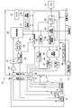
- FIG. 1 is a diagram illustrating an overall configuration of an endoscope apparatus according to the first embodiment.
- an endoscope apparatus 1 has an elongated and flexible insertion section 2 and the insertion section 2 is detachably connected, and is output from an image sensor mounted on the insertion section 2.
- a main body 3 that performs signal processing on an image pickup signal, and an LCD 4 as a display section that displays an image picked up by an image pickup device as an endoscopic image when an image signal output from the main body 3 is input. And is configured.
- a recording medium 5 can be attached to the main body 3, and still images and moving images can be recorded on the recording medium 5.
- detachable connectors 6a and 6b for electrical connection and bending wire connection mechanisms 7a and 7b for connecting a bending wire are arranged at the detachable portion between the insertion portion 2 and the main body portion 3, respectively.
- a rotation assist tool 14 that assists in automatically rotating a blade of a steam turbine, for example, is connected to the main body 3.
- the rotation assist tool 14 rotates a rotating body that is a subject such as a blade under the control of a rotation assist tool control unit 36 described later.
- An objective lens 8 is attached to the distal end portion of the insertion portion 2, and a charge coupled device (hereinafter abbreviated as CCD) 9 is disposed as an imaging device at the image forming position.
- CCD charge coupled device
- positioned in the image formation position of the objective lens 8 is not limited to CCD9, For example, CMOS may be sufficient.
- an illumination LED 10 that illuminates the subject
- a wire fixing portion 11 that fixes a bending wire
- a thermistor 12 that measures the temperature of the distal end portion, acceleration of the distal end portion, That is, an acceleration sensor 13 for detecting the movement of the tip is arranged.
- the main body 3 includes a preamplifier 20, an analog front end (hereinafter abbreviated as AFE) 21, an image processing unit 22, a timing generator 23, a CCD drive circuit 24, an LED drive circuit 25, and a bending control unit. 26, a UD bending motor 27, an RL bending motor 28, a user interface 29, a system control unit 30, a parameter storage unit 31, a power button 32, and a voltage conversion unit 33.
- the system control unit 30 includes an image recording unit 34, an LCD controller 35, and a rotation assist tool control unit 36. Further, a battery 37 is detachably attached to the main body 3. The voltage from the battery 37 is converted from, for example, 12 V to 3.3 V by the voltage conversion unit 33 and then supplied to each circuit including the system control unit 30.
- the illumination LED 10 disposed at the distal end portion of the insertion portion 2 is connected to the LED drive circuit 25 via a cable inserted into the insertion portion 2.
- the LED drive circuit 25 is connected to the system control unit 30.
- the LED drive circuit 25 controls the lighting / extinguishing of the LED 10 according to the LED lighting signal of the system control unit 30.
- the system control unit 30 receives an input (ON / OFF signal of the LED 10) from the user interface 29 and controls the LED drive circuit 25.
- a wire fixing portion 11 is disposed at the distal end portion of the insertion portion 2, and four wires are connected to the wire fixing portion 11. These four wires curve the tip in the vertical and horizontal directions, the two wires that control the vertical direction are connected to the UD bending motor 27, and the two wires that control the horizontal direction are RL.
- the bending motor 28 is connected. In FIG. 1, only one wire connected to each of the UD bending motor 27 and the RL bending motor 28 is shown.
- the UD bending motor 27 and the RL bending motor 28 are connected to the bending control unit 26, respectively.
- the bending control unit 26 is connected to the system control unit 30.
- the user interface 29 is equipped with a bending joystick that bends the distal end portion of the insertion unit 2.
- the system control unit 30 causes the bending control unit 26 to bend up and down.
- An instruction signal is transmitted.
- the bending control unit 26 drives and controls the UD bending motor 27 based on the received vertical bending instruction signal, and pulls the wire connected to the UD bending motor 27.
- tip part of the insertion part 2 can be curved to an up-down direction.
- the system control unit 30 transmits a left-right bending instruction signal to the bending control unit 26.
- the bending control unit 26 drives and controls the RL bending motor 28 based on the received left and right direction bending instruction signal, and pulls the wire connected to the RL bending motor 28.
- tip part of the insertion part 2 can be curved in the left-right direction.
- the subject illuminated by the LED 10 is imaged and photoelectrically converted on a CCD 9 as an imaging unit disposed at the imaging position of the objective lens 8 disposed at the distal end of the insertion unit 2.
- the composite coaxial cable connected to the CCD 9 is connected to the CCD drive circuit 24 and the preamplifier 20.
- the CCD drive circuit 24 receives a timing signal for driving the CCD 9 from the timing generator 23. Then, the CCD drive circuit 24 performs drive processing corresponding to the transmission path length to the CCD 9 (the length of the composite coaxial cable) on the received timing signal and transmits it to the CCD 9 as a CCD drive signal.
- the CCD 9 performs photoelectric conversion based on the timing of the CCD drive signal from the CCD drive circuit 24 and outputs a CCD output signal (imaging signal).
- This CCD output signal is input to the preamplifier 20 via a composite coaxial cable.
- the preamplifier 20 amplifies the CCD output signal to compensate for the signal level attenuated by transmission through the composite coaxial cable.
- the CCD output signal amplified by the preamplifier 20 is input to the AFE 21.
- the AFE 21 performs a CDS process (correlated double sampling process), an AGC process (auto gain control process), and an AD conversion process on the CCD output signal amplified by the preamplifier 20 and outputs the result to the image processing unit 22.
- CDS process correlated double sampling process
- AGC process auto gain control process
- AD conversion process on the CCD output signal amplified by the preamplifier 20 and outputs the result to the image processing unit 22.
- the image processing unit 22 performs various camera signal processing such as white balance, electronic ZOOM, color correction, contrast correction, AE control, and freeze on the signal obtained by the CCD 9.
- the image processing unit 22 communicates with the system control unit 30, and the system control unit 30 receives an input (ZOOM signal, Brightness signal, etc.) from the user interface 29, and sends an instruction corresponding to each to the image processing unit 22.
- the image processing unit 22 performs each process according to the instruction.
- the image processing unit 22 outputs the image signal subjected to each of these processes to the image recording unit 34 and the LCD controller 35.
- the image recording unit 34 controls still image recording and moving image recording.
- An image signal input to the image recording unit 34 via the image processing unit 22 is compressed by an encoder (not shown) in the image recording unit 34 and recorded on the recording medium 5 as a still image or a moving image.
- This image recording operation is performed when the system control unit 30 transmits a recording signal based on an input from the user interface 29 and the image recording unit 34 receives it.
- the image recording unit 34 performs still image shooting (still image recording) when recording is performed after the screen has been frozen once, and moving image shooting (still image recording when recording is performed without being frozen). Video recording).
- the still image or moving image recorded on the recording medium 5 is expanded by a decoder (not shown) in the image recording unit 34, output to the LCD controller 35, and output to the LCD 4.
- This image reproduction operation is performed when the system control unit 30 transmits a reproduction signal based on an input from the user interface 29 and the image recording unit 34 receives it.
- the image signal output from the image processing unit 22 or the image signal output from the image recording unit 34 is input to the LCD controller 35.
- the LCD controller 35 performs image processing (gamma correction, contour correction, scaling, RGB conversion, etc.) optimal for the connected LCD 4 on the image signal, and outputs an image to the LCD 4.
- the LCD 4 displays the image signal as a display image based on the input image signal.
- the thermistor 12 disposed at the distal end of the insertion unit 2 is connected to the system control unit 30 via a cable. Based on the information from the thermistor 12, the system control unit 30 displays temperature information at the tip of the insertion unit 2 on the LCD 4. In addition, when the temperature of the distal end portion of the insertion unit 2 becomes equal to or higher than a predetermined temperature, the system control unit 30 displays a temperature increase warning on the LCD 4.
- the parameter storage unit 31 is connected to the system control unit 30 and stores various parameters that are changed by a user operation, such as an input state from the user interface 29, an image processing parameter of the image processing unit 22, and a bending control parameter related to bending control. Can be remembered.
- the parameter storage unit 31 stores a predetermined threshold used for controlling the rotation assisting tool 14.
- the predetermined threshold value stored in the parameter storage unit 31 is input to the rotation assist tool control unit 36 of the system control unit 30.
- the predetermined threshold can be changed to an arbitrary value by the user using the user interface 29.
- the acceleration sensor 13 detects the acceleration at the distal end portion of the insertion portion 2. As described above, the acceleration sensor 13 constitutes a state detection unit that detects the movement of the distal end portion of the insertion portion 2, that is, the state of the distal end portion of the insertion portion 2. The detection result detected by the acceleration sensor 13 is input to the rotation assist tool controller 36.
- the rotation assisting tool control unit 36 as a control unit controls the rotation assisting tool 14 based on the detection result of the acceleration sensor 13. Further, the rotation assist tool control unit 36 controls the screen display of the LCD 4 based on the detection result of the acceleration sensor 13.
- the rotation assistance tool control unit 36 determines whether the movement amount of the distal end portion of the insertion unit 2 detected by the acceleration sensor 13 is equal to or greater than a predetermined value. Control the display. When the blade is not rotated by the rotation assisting tool 14 (for example, before the inspection), the rotation assisting tool control unit 36 warns the screen of the LCD 4 when the amount of movement of the distal end of the insertion part 2 is a predetermined value or more. Display.
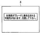
- FIG. 2 is a diagram showing an example of a warning display screen displayed on the LCD.
- the LCD 4 displays a warning message “There is a possibility that the tip may be caught in the blade.
- the rotation assisting control unit 36 When the amount of movement of the distal end portion of the insertion portion 2 is equal to or greater than a predetermined value, the rotation assisting control unit 36 generates a warning display shown in FIG. 2 and displays the warning display on the LCD 4 via the LCD controller 35.
- the rotation assisting tool control unit 36 selects the rotating body when the amount of movement of the distal end of the insertion part 2 is smaller than a predetermined value.
- the rotation auxiliary tool 14 is controlled to rotate.
- the rotation assisting tool control unit 36 rotates the rotating body by the rotation assisting tool 14 (for example, during inspection), when the amount of movement of the distal end portion of the insertion unit 2 becomes a predetermined value or more, The rotation assisting tool 14 is controlled so as to stop the rotation of the blade.
- the rotation assist tool control section 36 determines that the blade of the insertion section 2 is less than a predetermined value when the amount of movement is smaller than a predetermined value.
- the rotation auxiliary tool 14 is controlled so as to continue the rotation.
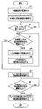
- FIG. 3 is a flowchart illustrating an example of the control of the rotation assist tool by the endoscope apparatus according to the first embodiment.
- the power supply of the endoscope apparatus 1 is turned on (S1), and the rotation assisting tool 14 is connected to the main body 3 (S2). Note that the order of S1 and S2 is reversed, that is, the power of the endoscope apparatus 1 may be turned on after the rotation assisting tool 14 is connected to the main body 3.
- the rotation assistance tool control unit 36 determines whether or not the start button has been pressed (S3).
- the start button is provided on the main body 3, for example, and an operation instruction for the start button is input to the rotation assisting tool control unit 36 via the user interface 29. If it is determined that the start button has not been pressed (S3: NO), the rotation assist tool control unit 36 returns to S3 and repeats the same processing. On the other hand, when it is determined that the start button is pressed (S3: YES), the rotation assisting tool control unit 36 determines whether or not the detection result of the acceleration sensor 13 is equal to or greater than a predetermined threshold (S4).
- the rotation assist tool control unit 36 displays a warning on the screen of the LCD 4 (S5). That is, when the rotation assisting tool control unit 36 detects that the distal end portion of the insertion portion 2 has a predetermined value or more based on the detection result of the acceleration sensor 13, the distal end portion can be caught in a rotating body such as a blade.
- the warning display is displayed on the LCD 4.
- the rotation assisting tool control unit 36 displays a warning on the screen of the LCD 4 for a predetermined time, and then deletes the warning display from the screen of the LCD 4 (S6). Then, it returns to S4 and repeats the same process.
- the rotation assist tool control unit 36 controls the rotation assist tool 14 to rotate the blade (S7). That is, when the rotation assisting tool control unit 36 determines that the distal end portion of the insertion portion 2 does not move beyond a predetermined value based on the detection result of the acceleration sensor 13, the distal end portion can be caught in a rotating body such as a blade. Rotate the blade so that the test can be started.
- the rotation assistance tool control unit 36 determines whether or not the detection result of the acceleration sensor 13 is equal to or greater than a predetermined threshold (S8). When it is determined that the detection result of the acceleration sensor 13 is not equal to or greater than the predetermined threshold value (S8: NO), the rotation assist tool control unit 36 returns to S8 and repeats the same processing. That is, when the rotation assisting tool control unit 36 determines that the distal end portion of the insertion portion 2 does not move beyond a predetermined value based on the detection result of the acceleration sensor 13, the distal end portion can be caught in a rotating body such as a blade. Continue to rotate the blade so that the inspection can continue.
- a predetermined threshold S8
- the rotation assist tool control unit 36 controls the rotation assist tool 14 to stop the rotation of the blade (S9).
- the process ends. That is, when the rotation assisting tool control unit 36 detects that the distal end portion of the insertion portion 2 has a predetermined value or more based on the detection result of the acceleration sensor 13, the distal end portion can be caught in a rotating body such as a blade. The blade rotation is stopped.
- the rotation assisting tool 14 is controlled so as to stop the rotation of the blade.
- a rotating body such as a blade
- shearing is performed.
- the blade may be controlled to rotate at a low speed with such an amount of force that does not occur.
- the processing content of S9 is “control the rotation assisting tool 14 so as to slow down the rotation of the blade”.
- the rotation assisting tool control unit 36 of the endoscope apparatus 1 determines the movement of the distal end portion based on the acceleration of the distal end portion of the insertion portion 2 detected by the acceleration sensor 13 and displays a warning on the LCD 4.
- the rotation assisting tool 14 is controlled.
- the rotation assist tool control unit 36 displays a warning on the LCD 4 before the inspection, and controls the rotation assist tool 14 to stop the rotation of the blade during the inspection.
- the endoscope apparatus 1 can prevent the distal end portion of the insertion portion 2 from being caught in a rotating body such as a blade.
- FIG. 4 is a diagram showing an overall configuration of the endoscope apparatus according to the second embodiment.
- the same components as those in FIG. 1 are denoted by the same reference numerals and description thereof is omitted.
- the acceleration sensor 13 is deleted from the endoscope apparatus 1 of FIG. 1, and a motion amount detection unit 40 is added to the image processing unit 22. Has been configured.
- the motion amount detection unit 40 compares a signal (image) obtained and input by the CCD 9 with a signal (image) one frame before and detects a motion amount (motion vector). As described above, the motion amount detection unit 40 detects the motion amount between the input image and the image input one frame before, so that the motion of the distal end portion of the insertion unit 2, that is, the insertion unit 2.
- the state detection part which detects the state of a front-end
- the rotation assist tool control unit 36 detects the movement of the distal end portion of the insertion unit 2 by comparing the motion amount input from the motion amount detection unit 40 with a predetermined threshold value, and controls the rotation assist tool control unit 36.
- control of the rotation assistance tool 14 by the rotation assistance tool control part 36 is the same as that of 1st Embodiment mentioned above.
- FIG. 5 is a diagram for explaining an example of an image obtained from the CCD.
- the image 44 obtained from the CCD 9 includes a region 42 through which the blade 41 passes and a region 43 through which the blade 41 does not pass when the blade 41 is rotated by the rotation assisting tool 14. To do.
- the movement amount detection unit 40 detects the movement amount of the region 42 through which the blade 41 passes, even if the distal end portion of the insertion portion 2 is not moving, the distal end portion of the insertion portion 2 is moved by the rotation assisting tool control unit 36. May be determined. Therefore, the movement amount detection unit 40 detects the movement amount of the region 43 where the blade 41 does not pass and outputs the movement amount to the rotation assisting tool control unit 36. Thereby, the rotation assistance tool control part 36 can determine correctly the motion of the front-end
- FIG. 6 is a flowchart illustrating an example of the control of the rotation assist tool by the endoscope apparatus according to the second embodiment.
- the same processes as those in FIG. 3 are denoted by the same reference numerals and description thereof is omitted.
- the rotation assisting tool control unit 36 determines whether or not the detection result of the motion amount detection unit 40 is equal to or greater than a predetermined threshold (S11). When it is determined that the detection result of the motion amount detection unit 40 is equal to or greater than the predetermined threshold value (S11: YES), the rotation assist tool control unit 36 proceeds to S5 and displays a warning on the screen of the LCD 4. That is, when the detection result of the movement amount detection unit 40 is equal to or greater than a predetermined threshold, the rotation assist tool control unit 36 determines that the tip portion may be caught in the blade, and performs a warning display illustrated in FIG. .
- the rotation assist tool control unit 36 proceeds to S7 and controls the rotation assist tool 14 to rotate the blade. To do. That is, when the detection result of the movement amount detection unit 40 is not equal to or greater than a predetermined threshold, the rotation assist tool control unit 36 determines that the tip portion is not likely to be caught in the blade, controls the rotation assist tool 14, and Rotate.
- the rotation assisting tool control unit 36 determines whether or not the detection result of the motion amount detection unit 40 is equal to or greater than a predetermined threshold (S12). When it is determined that the detection result of the motion amount detection unit 40 is not equal to or greater than the predetermined threshold (S12: NO), the rotation assist tool control unit 36 returns to S12 and repeats the same processing. That is, the rotation assisting tool control unit 36 determines that there is no possibility of the tip portion being caught in the blade when the blade does not detect movement at the tip portion of the insertion portion 2, and continues to rotate the blade. The rotation assist tool 14 is controlled.
- the rotation assist tool control unit 36 proceeds to S9 and stops the rotation of the blade. 14 is controlled. That is, when the rotation assisting tool control unit 36 detects movement at the distal end portion of the insertion portion 2 while rotating the blade, it determines that the distal end portion may be caught in the blade, and stops the rotation of the blade. The rotation assisting tool 14 is controlled.
- the rotation assisting tool control unit 36 of the endoscope apparatus 1a determines the movement of the distal end portion of the insertion unit 2 based on the motion amount (motion vector) of the image detected by the motion amount detection unit 40.
- the warning display on the LCD 4 or the rotation assisting tool 14 is controlled.
- the rotation assist tool control unit 36 displays a warning on the LCD 4 before the inspection, and controls the rotation assist tool 14 to stop the rotation of the blade during the inspection.
- the endoscope apparatus 1a can prevent the distal end portion of the insertion portion 2 from being caught in a rotating body such as a blade.
- the endoscope apparatus 1a of the present embodiment similarly to the endoscope apparatus 1 of the first embodiment, the distal end portion of the insertion portion 2 is not caught in the rotating body, and safety is ensured. be able to. Moreover, since the endoscope apparatus 1a of this embodiment does not need to provide the acceleration sensor 13 shown in FIG. 1 in the front-end
- the main body unit 3 is provided with the motion amount detection unit 40 that detects the motion amount between the input image and the image input one frame before.
- the main body 3 may be provided outside (for example, a cloud).
- the endoscope apparatus 1a transmits an image captured by the CCD 9 to the outside, and detects the amount of movement outside. And endoscope apparatus 1a may receive the amount of movement transmitted from the outside, and may make it control rotation auxiliary tool 14 based on the received amount of movement.
- FIG. 7 is a diagram illustrating an overall configuration of an endoscope apparatus according to the third embodiment.
- the same components as those in FIG. 1 are denoted by the same reference numerals and description thereof is omitted.
- the acceleration sensor 13 is deleted from the endoscope apparatus 1 of FIG. 1, and a measurement unit 50 is added to the system control unit 30. It is configured.
- the image signal that has been subjected to predetermined processing by the image processing unit 22 is input to the measurement unit 50.
- the measurement unit 50 measures the distance from the distal end of the insertion unit 2 to the blade that is the subject using the input image signal, and outputs the measurement result to the rotation assisting tool control unit 36.
- the measurement of the distance from the tip of the insertion section 2 to the blade by the measurement section 50 is performed using a known technique.
- the distal end portion of the insertion unit 2 includes two observation optical systems having parallax on the left and right sides, and the measurement unit 50 is inserted on the principle of triangulation using observation images having parallax from the two left and right observation optical systems.
- the distance from the tip of the part 2 to the blade is measured (stereo measurement).
- blade is not limited to a stereo measurement.
- the TOF (Time of Flight) method which measures the phase difference between the laser light irradiated on the subject and the reflected light, or the subject is irradiated with laser light and the movement of the reflected light is the principle of triangulation
- the distance to the blade may be measured using a triangulation method or the like that is measured in step (b).
- the measurement unit 50 constitutes a state detection unit that detects the state of the distal end portion of the insertion portion 2 by measuring the distance from the distal end of the insertion portion 2 to the blade.
- the measurement result measured by the measurement unit 50 is input to the rotation assist tool control unit 36.
- the rotation assisting tool control unit 36 determines whether the distal end portion of the insertion unit 2 is too close to the blade by comparing the measurement result input from the measuring unit 50 with a predetermined threshold, and the rotation assisting tool control unit 36 is controlled.
- the rotation assisting tool control unit 36 determines that the distal end portion of the insertion unit 2 is too close to the blade (the distal end portion may be caught in the blade).
- the rotation assisting tool 14 is controlled to display a warning on the screen of the LCD 4 or to stop the rotation of the blade.
- the rotation assisting tool control unit 36 determines that the distal end portion of the insertion portion 2 is not too close to the blade (the possibility that the distal end portion is caught in the blade).
- the rotation assisting tool 14 is controlled so as to rotate the blade or continue to rotate the blade.
- FIG. 8 is a flowchart illustrating an example of the control of the rotation assist tool by the endoscope apparatus according to the third embodiment. In FIG. 8, the same processes as those in FIG.
- the rotation assisting tool control unit 36 determines whether the measurement result of the measurement unit 50 is equal to or less than a predetermined threshold (S21). When it is determined that the measurement result of the measurement unit 50 is equal to or less than the predetermined threshold (S21: YES), the rotation assisting tool control unit 36 proceeds to S5 and displays a warning on the screen of the LCD 4. That is, when the measurement result of the measurement unit 50 is equal to or less than the predetermined threshold, the rotation assisting tool control unit 36 has the distal end portion of the insertion unit 2 too close to the blade (the distal end portion may be caught in the blade). ) And display the warning shown in FIG.
- the rotation assist tool control unit 36 proceeds to S7 and controls the rotation assist tool 14 to rotate the blade. That is, when the measurement result of the measuring unit 50 is not equal to or less than the predetermined threshold, the rotation assisting tool control unit 36 does not approach the blade too much (there is no possibility of the tip being caught by the blade). And the rotation assisting tool 14 is controlled to rotate the blade.
- the rotation assisting tool control unit 36 determines whether or not the measurement result of the measurement unit 50 is equal to or less than a predetermined threshold (S22). When it is determined that the measurement result of the measurement unit 50 is not equal to or less than the predetermined threshold value (S22: NO), the rotation assist tool control unit 36 returns to S22 and repeats the same processing. That is, when the rotation assisting tool control unit 36 detects that the tip is not approaching the blade while rotating the blade, it determines that the tip is not likely to be caught in the blade, and continues to rotate the blade. The rotation assisting tool 14 is controlled.
- the rotation assisting tool control unit 36 determines that the measurement result of the measuring unit 50 is equal to or less than the predetermined threshold (S22: YES)
- the rotation assisting tool control unit 36 proceeds to S9 and sets the rotation assisting tool 14 to stop the rotation of the blade. Control. That is, when the rotation assisting tool control unit 36 detects that the tip is too close to the blade while rotating the blade, it determines that the tip may be caught in the blade and stops the rotation of the blade. The rotation assisting tool 14 is controlled to do so.
- the rotation assist tool control unit 36 of the endoscope apparatus 1b determines the distance between the tip of the insertion unit 2 and the blade based on the measurement result measured by the measurement unit 50, and displays a warning on the LCD 4 Alternatively, the rotation assisting tool 14 is controlled. When it is determined that the tip is too close to the blade, the rotation assist tool control unit 36 displays a warning on the LCD 4 before the inspection, and controls the rotation assist tool 14 to stop the rotation of the blade during the inspection. . As a result, the endoscope apparatus 1b can prevent the distal end portion of the insertion portion 2 from being caught in a rotating body such as a blade.
- the endoscope apparatus 1b of the present embodiment similarly to the endoscope apparatus 1 of the first embodiment, the distal end portion of the insertion portion 2 is not caught in the rotating body, and safety is ensured. be able to. Moreover, since the endoscope apparatus 1b of this embodiment does not need to provide the acceleration sensor 13 shown in FIG. 1 in the front-end
- the measurement unit 50 that measures the distance from the distal end of the insertion unit 2 to the blade that is the subject is provided in the main body unit 3, but the measurement unit 50 is provided outside the main body unit 3 (for example, , Cloud).
- the endoscope apparatus 1b transmits an observation image having parallax from the left and right observation optical systems to the outside, and measures the distance from the distal end of the insertion portion 2 to the blade using the observation image having parallax on the outside. To do.
- endoscope apparatus 1b may control rotation auxiliary tool 14 based on the measurement result transmitted from the outside.
- FIG. 9 is a diagram showing an overall configuration of an endoscope apparatus according to the fourth embodiment.
- the same components as those in FIGS. 1, 4, and 7 are denoted by the same reference numerals and description thereof is omitted.
- an endoscope apparatus 1 c according to the fourth embodiment includes an acceleration sensor 13 in FIG. 1 at the distal end of the insertion unit 2, a motion amount detection unit 40 in FIG. 4 in the image processing unit 22, and system control.
- the unit 30 is configured to have the measurement unit 50 of FIG.
- the endoscope apparatus 1c according to the fourth embodiment is configured by combining the endoscope apparatuses 1, 1a, and 1b according to the first, second, and third embodiments.
- the rotation assist tool control unit 36 receives the detection result of the acceleration sensor 13, the detection result of the motion amount detection unit 40, and the measurement result of the measurement unit 50.
- the rotation assist control unit 36 determines whether the detection result of the acceleration sensor 13 is equal to or greater than a first predetermined threshold, whether the detection result of the motion amount detection unit 40 is equal to or greater than a second predetermined threshold, or a measurement unit
- the rotation assisting tool 14 is controlled according to whether the 50 measurement results are equal to or less than a third predetermined threshold value.
- the rotation assist tool control unit 36 displays a warning on the screen of the LCD 4 when any one of the detection result of the acceleration sensor 13, the detection result of the motion amount detection unit 40, and the measurement result of the measurement unit 50 is abnormal.
- the rotation auxiliary tool 14 is controlled so as to stop the rotation of the blade. More specifically, the rotation assisting tool control unit 36 determines that the detection result of the acceleration sensor 13 is equal to or greater than a first predetermined threshold, the detection result of the motion amount detection unit 40 is equal to or greater than a second predetermined threshold, or a measurement unit.
- a warning is displayed on the screen of the LCD 4 or the rotation assisting tool 14 is controlled so as to stop the rotation of the blade.
- the rotation assisting tool control unit 36 rotates the blade when the detection result of the acceleration sensor 13, the detection result of the movement amount detection unit 40, and the measurement result of the measurement unit 50 are all abnormal.
- the rotation auxiliary tool 14 is controlled so as to continue to rotate. More specifically, the rotation assist tool control unit 36 has a detection result of the acceleration sensor 13 that is not equal to or greater than a first predetermined threshold value, and a detection result of the motion amount detection unit 40 is not equal to or greater than a second predetermined threshold value. And when the measurement result of the measurement part 50 is not below a 3rd predetermined threshold value, the rotation assistance tool 14 is controlled so that a blade may be rotated or it may continue rotating.
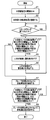
- FIG. 10 is a flowchart illustrating an example of the control of the rotation assist tool by the endoscope apparatus according to the fourth embodiment.
- FIG. 10 the same processing as in FIG. 10.
- the rotation assisting tool control unit 36 determines that the detection result of the acceleration sensor 13 is equal to or greater than the first predetermined threshold, and the detection result of the motion amount detection unit 40 is the second predetermined threshold. Whether or not the measurement result of the measurement unit 50 is equal to or smaller than a third predetermined threshold value is determined (S31).
- the rotation assisting tool control unit 36 has a detection result of the acceleration sensor 13 that is equal to or greater than a first predetermined threshold, a detection result of the motion amount detection unit 40 that is equal to or greater than a second predetermined threshold, or a measurement result of the measurement unit 50 that is the first.
- the process proceeds to S5, and a warning is displayed on the screen of the LCD 4. That is, the rotation assisting tool control unit 36 determines that the tip of the insertion unit 2 is abnormal when any one of the detection result of the acceleration sensor 13, the detection result of the motion amount detection unit 40, and the measurement result of the measurement unit 50 is abnormal. 2 is determined to possibly be caught in the blade, and a warning display shown in FIG. 2 is performed.
- the rotation assisting tool control unit 36 determines that the detection result of the acceleration sensor 13 is equal to or greater than the first predetermined threshold, the detection result of the motion amount detection unit 40 is equal to or greater than the second predetermined threshold, or the measurement result of the measurement unit 50. Is determined not to be equal to or less than the third predetermined threshold (S31: NO), the process proceeds to S7, and the rotation assisting tool 14 is controlled to rotate the blade. That is, when there is no abnormality in all of the detection result of the acceleration sensor 13, the detection result of the movement amount detection unit 40, and the measurement result of the measurement unit 50, the rotation assist tool control unit 36 determines that the distal end portion of the insertion unit 2 is a blade. The rotation assisting tool 14 is controlled to rotate the blade.
- the rotation assisting tool control unit 36 causes the detection result of the acceleration sensor 13 to be greater than or equal to the first predetermined threshold, and the detection result of the motion amount detection unit 40 is greater than or equal to the second predetermined threshold, or Then, it is determined whether or not the measurement result of the measurement unit 50 is equal to or smaller than a third predetermined threshold (S32).
- the rotation assisting tool control unit 36 has a detection result of the acceleration sensor 13 that is equal to or greater than a first predetermined threshold, a detection result of the motion amount detection unit 40 that is equal to or greater than a second predetermined threshold, or a measurement result of the measurement unit 50 that is the first.
- the process returns to S32 and the same process is repeated. That is, when there is no abnormality in all of the detection result of the acceleration sensor 13, the detection result of the movement amount detection unit 40, and the measurement result of the measurement unit 50, the rotation assist tool control unit 36 determines that the distal end portion of the insertion unit 2 is a blade. The rotation assisting tool 14 is controlled so that the blade continues to rotate.
- the rotation assisting tool control unit 36 determines that the detection result of the acceleration sensor 13 is equal to or greater than the first predetermined threshold, the detection result of the motion amount detection unit 40 is equal to or greater than the second predetermined threshold, or the measurement result of the measurement unit 50. Is determined to be equal to or smaller than the third predetermined threshold (S32: YES), the process proceeds to S9, and the rotation assisting tool 14 is controlled so as to stop the rotation of the blade. That is, the rotation assisting tool control unit 36 determines that the tip of the insertion unit 2 is abnormal when any one of the detection result of the acceleration sensor 13, the detection result of the motion amount detection unit 40, and the measurement result of the measurement unit 50 is abnormal. The rotation assisting tool 14 is controlled so as to stop the rotation of the blade.
- the rotation assisting tool control unit 36 of the endoscope apparatus 1 c is based on the detection result of the acceleration sensor 13, the detection result of the motion amount detection unit 40, and the measurement result of the measurement unit 50.
- the movement of the distal end portion and the distance between the distal end portion of the insertion portion 2 and the blade are determined, and a warning display on the LCD 4 or the rotation assisting tool 14 is controlled.
- the rotation assisting tool control unit 36 displays a warning on the LCD 4 before the inspection, and stops the rotation of the blade during the inspection.
- the rotation assisting tool 14 is controlled.
- the endoscope apparatus 1c can prevent the distal end portion of the insertion portion 2 from being caught in a rotating body such as a blade.
- the endoscope apparatus 1c of this embodiment similarly to the endoscope apparatus 1 of the first embodiment, the distal end portion of the insertion portion 2 is not caught in the rotating body, and safety is ensured. be able to.
- the endoscope apparatus 1c according to the present embodiment determines the state of the insertion unit 2 based on the detection result of the acceleration sensor 13, the detection result of the motion amount detection unit 40, and the measurement result of the measurement unit 50. Compared with the endoscope apparatuses 1, 1a, and 1b of the first, second, and third embodiments, the state of the insertion portion 2 can be detected with higher accuracy, and the safety can be improved.
- the rotation assisting tool control unit 36 controls the rotation assisting tool 14 using the detection result of the acceleration sensor 13, the detection result of the motion amount detection unit 40, and the measurement result of the measurement unit 50.
- the rotation assist tool control unit 36 uses any two results among the detection result of the acceleration sensor 13, the detection result of the motion amount detection unit 40, and the measurement result of the measurement unit 50, and uses the rotation assist tool 14. May be controlled.
- each step in the flowcharts in this specification may be executed in a different order for each execution by changing the execution order and executing a plurality of steps at the same time, as long as it does not violate its nature.
Landscapes
- Physics & Mathematics (AREA)
- Astronomy & Astrophysics (AREA)
- General Physics & Mathematics (AREA)
- Optics & Photonics (AREA)
- Instruments For Viewing The Inside Of Hollow Bodies (AREA)
- Endoscopes (AREA)
Abstract
内視鏡装置1は、挿入部2と、挿入部2の状態を検出する状態検出部と、状態検出部の検出結果に基づいて、被検体である回転体を回転させる回転補助具14の動きを制御する回転補助具制御部36と、を有する。
Description
本発明は、内視鏡装置及び内視鏡装置の制御方法に関し、特に、回転体を回転させる回転補助具を制御する内視鏡装置及び内視鏡装置の制御方法に関する。
従来、体腔内に細長の挿入部を挿入することにより、体腔内臓器等を観察したり、必要に応じ処置具チャンネル内に挿通した処置具を用いて各種治療処置のできる内視鏡装置が広く利用されている。また、工業用分野においても、ボイラ、タービン、エンジン、化学プラント等の内部の傷、腐食等の観察、検査に工業用内視鏡装置が広く用いられている。
周知のように、発電所では例えば蒸気タービン等が使用されており、蒸気タービンのタービンブレード(以下、単にブレードと呼ぶ)の摩耗や損傷等の検査を行うために、工業用の内視鏡装置が用いられている。
このような蒸気タービンの検査では、全てのブレードを検査するために内視鏡挿入部(以下、単に挿入部と呼ぶ)の先端部を蒸気タービンに設けられたアクセスポイント(アクセスポート)から挿入する。そして、ブレードが観察できる位置に挿入部の先端部を配置した状態で、ブレードを1周回転させて検査させる手法が存在する。このような手法では、検査効率を向上させるためにブレードを自動で回転させる回転補助具が使用されている(例えば、日本国特開2007-113412号公報)。
しかしながら、回転補助具を使用したブレードの検査では、挿入部の先端部が被検体であるブレードに近づき過ぎると、挿入部の先端部がブレードに巻き込まれる可能性がある。挿入部の先端部がブレードに巻き込まれると、挿入部の先端部が破損したり、ブレードに損傷を与えてしまう虞がある。
さらに、例えば、挿入部の先端部がせん断されて蒸気タービン内に取り残される状態となった場合には、蒸気タービンが正常動作できない。そのため、蒸気タービンを分解して、せん断された挿入部の先端部を取り除く必要があり、非常に手間がかかる。
そこで、本発明は、挿入部の先端部が回転体に巻き込まれることなく、安全性を確保することができる内視鏡装置及び内視鏡装置の制御方法を提供することを目的とする。
本発明の一態様の内視鏡装置は、挿入部と、前記挿入部の状態を検出する状態検出部と、前記状態検出部の検出結果に基づいて、被検体である回転体を回転させる回転補助具の動きを制御する制御部と、を有する。
本発明の一態様の内視鏡装置の制御方法は、挿入部の状態を検出する状態検出ステップと、前記状態検出ステップの検出結果に基づいて、被検体である回転体を回転させる回転補助具の動きを制御する制御ステップと、を有する。
以下、図面を参照して本発明の実施の形態について詳細に説明する。
(第1の実施形態)
まず、図1を用いて、本発明の第1の実施の形態の内視鏡装置の構成について説明する。図1は、第1の実施形態に係る内視鏡装置の全体構成を示す図である。
まず、図1を用いて、本発明の第1の実施の形態の内視鏡装置の構成について説明する。図1は、第1の実施形態に係る内視鏡装置の全体構成を示す図である。
(全体構成)
図1に示すように、内視鏡装置1は、細長で可撓性を有する挿入部2と、この挿入部2が着脱自在に接続され、挿入部2に搭載された撮像素子から出力された撮像信号に対して信号処理を行う本体部3と、この本体部3から出力される画像信号が入力されることにより撮像素子で撮像された画像を内視鏡画像として表示する表示部としてのLCD4とを有して構成されている。
図1に示すように、内視鏡装置1は、細長で可撓性を有する挿入部2と、この挿入部2が着脱自在に接続され、挿入部2に搭載された撮像素子から出力された撮像信号に対して信号処理を行う本体部3と、この本体部3から出力される画像信号が入力されることにより撮像素子で撮像された画像を内視鏡画像として表示する表示部としてのLCD4とを有して構成されている。
本体部3には、記録媒体5が取り付け可能となっており、記録媒体5に静止画、動画記録が可能となっている。また、挿入部2と本体部3との着脱部分には、それぞれ電気的な接続を行うための着脱コネクタ6a及び6b、湾曲用ワイヤを接続する湾曲ワイヤ接続機構7a及び7bが配置されている。さらに、本体部3には、例えば蒸気タービンのブレード等を自動的に回転させることを補助する回転補助具14が接続される。回転補助具14は、後述する回転補助具制御部36の制御によって、ブレード等の被検体である回転体を回転させる。
挿入部2の先端部には、対物レンズ8が取り付けてあり、その結像位置に撮像素子として例えば電荷結合素子(以下、CCDと略記)9が配置されている。なお、対物レンズ8の結像位置に配置される撮像素子は、CCD9に限定されることなく、例えばCMOSであってもよい。また、挿入部2の先端部には、被検体を照明する照明用のLED10と、湾曲用ワイヤを固定するワイヤ固定部11と、先端部の温度を計測するサーミスタ12と、先端部の加速度、すなわち、先端部の動きを検出するための加速度センサ13とが配置されている。
また、本体部3は、プリアンプ20と、アナログフロントエンド(以下、AFEと略記)21と、画像処理部22と、タイミングジェネレータ23と、CCDドライブ回路24と、LEDドライブ回路25と、湾曲制御部26と、UD湾曲モータ27と、RL湾曲モータ28と、ユーザインターフェース29と、システム制御部30と、パラメータ記憶部31と、電源ボタン32と、電圧変換部33とを有して構成される。システム制御部30は、画像記録部34と、LCDコントローラ35と、回転補助具制御部36とを有して構成される。さらに、本体部3には、バッテリ37が着脱自在に構成されている。バッテリ37からの電圧は、電圧変換部33により、例えば12Vから3.3Vに変換された後、システム制御部30を含めた各回路に供給される。
(LED制御)
挿入部2の先端部に配置された照明用のLED10は、挿入部2内に挿通されたケーブルを介してLEDドライブ回路25と接続されている。このLEDドライブ回路25は、システム制御部30と接続されている。LEDドライブ回路25は、システム制御部30のLED点灯信号により、LED10の点灯/消灯を制御する。システム制御部30は、ユーザインターフェース29からの入力(LED10のON/OFF信号)を受け取り、LEDドライブ回路25を制御する。
挿入部2の先端部に配置された照明用のLED10は、挿入部2内に挿通されたケーブルを介してLEDドライブ回路25と接続されている。このLEDドライブ回路25は、システム制御部30と接続されている。LEDドライブ回路25は、システム制御部30のLED点灯信号により、LED10の点灯/消灯を制御する。システム制御部30は、ユーザインターフェース29からの入力(LED10のON/OFF信号)を受け取り、LEDドライブ回路25を制御する。
(湾曲制御)
挿入部2の先端部にはワイヤ固定部11が配置されており、このワイヤ固定部11に4本のワイヤが接続されている。それらの4本のワイヤは、先端部を上下左右方向に湾曲させるものであり、上下方向を制御する2本のワイヤはUD湾曲モータ27に接続され、左右方向を制御する2本のワイヤはRL湾曲モータ28に接続されている。なお、図1においては、UD湾曲モータ27及びRL湾曲モータ28に接続されるワイヤをそれぞれ1本のみ記載している。
挿入部2の先端部にはワイヤ固定部11が配置されており、このワイヤ固定部11に4本のワイヤが接続されている。それらの4本のワイヤは、先端部を上下左右方向に湾曲させるものであり、上下方向を制御する2本のワイヤはUD湾曲モータ27に接続され、左右方向を制御する2本のワイヤはRL湾曲モータ28に接続されている。なお、図1においては、UD湾曲モータ27及びRL湾曲モータ28に接続されるワイヤをそれぞれ1本のみ記載している。
UD湾曲モータ27、及び、RL湾曲モータ28は、それぞれ湾曲制御部26に接続されている。この湾曲制御部26は、システム制御部30に接続さている。
ユーザインターフェース29には、挿入部2の先端部を湾曲させる湾曲用ジョイスティックが搭載されており、その湾曲用ジョイスティックを上下方向に傾倒されると、システム制御部30は湾曲制御部26に上下方向湾曲指示信号を送信する。湾曲制御部26は、受信した上下方向湾曲指示信号に基づいて、UD湾曲モータ27を駆動制御してUD湾曲モータ27に接続さているワイヤを牽引する。それにより、挿入部2の先端部を上下方向に湾曲することができる。
左右方向の湾曲も同様に、挿入部2の先端部を湾曲させる湾曲用ジョイスティックが左右方向に傾倒されると、システム制御部30は湾曲制御部26に左右方向湾曲指示信号を送信する。湾曲制御部26は、受信した左右方向湾曲指示信号に基づいてRL湾曲モータ28を駆動制御してRL湾曲モータ28に接続さているワイヤを牽引する。それにより、挿入部2の先端部を左右方向に湾曲することができる。
(画像処理)
LED10により照明された被写体は、挿入部2の先端部に配置された対物レンズ8の結像位置に配置された、撮像部としてのCCD9に結像され、光電変換される。このCCD9に接続される複合同軸ケーブルは、CCDドライブ回路24及びプリアンプ20に接続される。
LED10により照明された被写体は、挿入部2の先端部に配置された対物レンズ8の結像位置に配置された、撮像部としてのCCD9に結像され、光電変換される。このCCD9に接続される複合同軸ケーブルは、CCDドライブ回路24及びプリアンプ20に接続される。
CCDドライブ回路24は、タイミングジェネレータ23から、CCD9を駆動するためのタイミング信号を受信する。そして、CCDドライブ回路24は、受信したタイミング信号に対して、CCD9までの伝送路長(複合同軸ケーブルの長さ)に応じたドライブ処理を施して、CCD駆動信号としてCCD9に伝送する。
CCD9は、CCDドライブ回路24からのCCD駆動信号のタイミングに基づいて光電変換を行い、CCD出力信号(撮像信号)を出力する。このCCD出力信号は、複合同軸ケーブルを介してプリアンプ20に入力される。プリアンプ20は、複合同軸ケーブルでの伝送により減衰した信号レベルを補うためにCCD出力信号を増幅する。
プリアンプ20により増幅されたCCD出力信号は、AFE21に入力される。AFE21は、プリアンプ20により増幅されたCCD出力信号に、CDS処理(相関2重サンプリング処理)、AGC処理(オートゲインコントロール処理)、及びAD変換処理を施し、画像処理部22に出力する。
画像処理部22は、CCD9により得られた信号に対して、ホワイトバランス、電子ZOOM、色補正、コントラスト補正、AE制御、フリーズ等の各種カメラ信号処理を行う。画像処理部22は、システム制御部30と通信を行い、システム制御部30がユーザインターフェース29からの入力(ZOOM信号、Brightness信号等)を受け取り、それぞれに対応した指示を画像処理部22に対して出力し、その指示に従って画像処理部22が各処理を行う。画像処理部22は、これらの各処理を行った画像信号を画像記録部34及びLCDコントローラ35に出力する。
(画像記録)
画像記録部34は、静止画記録、動画記録の制御を行う。画像記録部34に画像処理部22を介して入力された画像信号は、画像記録部34内の図示しないエンコーダにより圧縮され、静止画、若しくは動画として記録媒体5に記録される。この画像記録動作は、システム制御部30がユーザインターフェース29からの入力に基づいて記録信号を送信して、それを画像記録部34が受信した場合に行われる。なお、画像記録部34は、一旦画面のフリーズが実施しされた後に記録をする場合には静止画撮影(静止画記録)を行い、フリーズが実施されずに記録をする場合には動画撮影(動画記録)を行う。
画像記録部34は、静止画記録、動画記録の制御を行う。画像記録部34に画像処理部22を介して入力された画像信号は、画像記録部34内の図示しないエンコーダにより圧縮され、静止画、若しくは動画として記録媒体5に記録される。この画像記録動作は、システム制御部30がユーザインターフェース29からの入力に基づいて記録信号を送信して、それを画像記録部34が受信した場合に行われる。なお、画像記録部34は、一旦画面のフリーズが実施しされた後に記録をする場合には静止画撮影(静止画記録)を行い、フリーズが実施されずに記録をする場合には動画撮影(動画記録)を行う。
また、記録媒体5に記録されている静止画、若しくは動画は、画像記録部34内の図示しないデコーダにより伸張され、LCDコントローラ35に出力され、LCD4に出力される。この画像再生動作は、システム制御部30がユーザインターフェース29からの入力に基づいて再生信号を送信して、それを画像記録部34が受信した場合に行われる。
(LCD表示)
画像処理部22より出力された画像信号、あるいは、画像記録部34より出力された画像信号は、LCDコントローラ35に入力される。LCDコントローラ35は、接続されているLCD4に最適な画像処理(ガンマ補正、輪郭補正、スケーリング、RGB変換、等)を画像信号に施し、LCD4に画像を出力する。LCD4は、入力された画像信号に基づき画像信号を表示画像として表示する。
画像処理部22より出力された画像信号、あるいは、画像記録部34より出力された画像信号は、LCDコントローラ35に入力される。LCDコントローラ35は、接続されているLCD4に最適な画像処理(ガンマ補正、輪郭補正、スケーリング、RGB変換、等)を画像信号に施し、LCD4に画像を出力する。LCD4は、入力された画像信号に基づき画像信号を表示画像として表示する。
(温度制御)
挿入部2の先端部に配置されたサーミスタ12は、ケーブルを介してシステム制御部30と接続されている。システム制御部30は、サーミスタ12からの情報に基づき、挿入部2の先端の温度情報をLCD4に表示する。また、システム制御部30は、挿入部2の先端部の温度が所定の温度以上になった場合、温度上昇の警告をLCD4に表示する。
挿入部2の先端部に配置されたサーミスタ12は、ケーブルを介してシステム制御部30と接続されている。システム制御部30は、サーミスタ12からの情報に基づき、挿入部2の先端の温度情報をLCD4に表示する。また、システム制御部30は、挿入部2の先端部の温度が所定の温度以上になった場合、温度上昇の警告をLCD4に表示する。
(パラメータ保持)
パラメータ記憶部31は、システム制御部30に接続されており、ユーザインターフェース29からの入力状態、画像処理部22の画像処理パラメータ、湾曲制御に関する湾曲制御パラメータ等、ユーザ操作により変更される各種パラメータを記憶することができる。
パラメータ記憶部31は、システム制御部30に接続されており、ユーザインターフェース29からの入力状態、画像処理部22の画像処理パラメータ、湾曲制御に関する湾曲制御パラメータ等、ユーザ操作により変更される各種パラメータを記憶することができる。
また、パラメータ記憶部31は、回転補助具14の制御に用いる所定の閾値を記憶している。パラメータ記憶部31に記憶された所定の閾値は、システム制御部30の回転補助具制御部36に入力される。なお、所定の閾値は、ユーザインターフェース29を用いてユーザが任意の値に変更することができる。
(回転補助具の制御)
加速度センサ13は、挿入部2の先端部の加速度を検出する。このように、加速度センサ13は、挿入部2の先端部の動き、すなわち、挿入部2の先端部の状態を検出する状態検出部を構成する。加速度センサ13により検出された検出結果は、回転補助具制御部36に入力される。
加速度センサ13は、挿入部2の先端部の加速度を検出する。このように、加速度センサ13は、挿入部2の先端部の動き、すなわち、挿入部2の先端部の状態を検出する状態検出部を構成する。加速度センサ13により検出された検出結果は、回転補助具制御部36に入力される。
制御部としての回転補助具制御部36は、加速度センサ13の検出結果に基づいて回転補助具14を制御する。また、回転補助具制御部36は、加速度センサ13の検出結果に基づいてLCD4の画面表示を制御する。
より具体的には、回転補助具制御部36は、加速度センサ13によって検出された挿入部2の先端部の動き量が所定の値以上か否かに基づいて、回転補助具14及びLCD4の画面表示を制御する。回転補助具制御部36は、回転補助具14によりブレードを回転させていないときに(例えば、検査前)、挿入部2の先端部の動き量が所定の値以上の場合、LCD4の画面に警告表示を行う。
図2は、LCDに表示される警告表示の画面の一例を示す図である。図2に示すように、LCD4には、例えば、「先端部がブレードに巻き込まれる可能性があります。注意して下さい。」という警告表示が表示される。回転補助具制御部36は、挿入部2の先端部の動き量が所定の値以上の場合、図2に示す警告表示を生成し、LCDコントローラ35を介してLCD4に警告表示を表示させる。
また、回転補助具制御部36は、回転補助具14によりブレードを回転させていないときに(例えば、検査前)、挿入部2の先端部の動き量が所定の値より小さい場合、回転体を回転させるように回転補助具14を制御する。
また、回転補助具制御部36は、回転補助具14により回転体を回転させているときに(例えば、検査中)、挿入部2の先端部の動き量が所定の値以上になった場合、ブレードの回転を停止するように回転補助具14を制御する。
また、回転補助具制御部36は、回転補助具14により回転体を回転させているときに(例えば、検査中)、挿入部2の先端部の動き量が所定の値より小さい場合、ブレードの回転を継続するように回転補助具14を制御する。
次に、このように構成された内視鏡装置1の動作について説明する。図3は、第1の実施形態の内視鏡装置による回転補助具の制御の一例を示すフローチャートである。
まず、内視鏡装置1の電源がONされ(S1)、回転補助具14が本体部3に接続される(S2)。なお、S1及びS2の順番は逆、すなわち、回転補助具14が本体部3に接続された後、内視鏡装置1の電源がONされてもよい。
次に、回転補助具制御部36は、スタートボタンが押下されたか否かを判定する(S3)。このスタートボタンは、例えば本体部3に設けられており、スタートボタンの操作指示は、ユーザインターフェース29を介して回転補助具制御部36に入力される。回転補助具制御部36は、スタートボタンが押下されていないと判定した場合(S3:NO)、S3に戻り同様の処理を繰り返す。一方、回転補助具制御部36は、スタートボタンが押下されたと判定した場合、(S3:YES)、加速度センサ13の検出結果が所定の閾値以上か否かを判定する(S4)。
回転補助具制御部36は、加速度センサ13の検出結果が所定の閾値以上と判定した場合(S4:YES)、LCD4の画面に警告表示を行う(S5)。すなわち、回転補助具制御部36は、加速度センサ13の検出結果に基づき、挿入部2の先端部に所定値以上の動きがあると検出した場合、先端部がブレード等の回転体に巻き込まれる可能性があると判断し、LCD4に警告表示を表示する。回転補助具制御部36は、所定の時間、LCD4の画面に警告表示を行った後、LCD4の画面から警告表示を消去する(S6)。その後、S4に戻り、同様の処理を繰り返す。
一方、回転補助具制御部36は、加速度センサ13の検出結果が所定の閾値以上でない判定した場合(S4:NO)、ブレードを回転させるように回転補助具14を制御する(S7)。すなわち、回転補助具制御部36は、加速度センサ13の検出結果に基づき、挿入部2の先端部に所定値以上の動きがないと判断した場合、先端部がブレード等の回転体に巻き込まれる可能性がないと判断し、検査が開始できるようにブレードを回転させる。
次に、回転補助具制御部36は、加速度センサ13の検出結果が所定の閾値以上か否かを判定する(S8)。回転補助具制御部36は、加速度センサ13の検出結果が所定の閾値以上でないと判定した場合(S8:NO)、S8に戻り、同様の処理を繰り返す。すなわち、回転補助具制御部36は、加速度センサ13の検出結果に基づき、挿入部2の先端部に所定値以上の動きがないと判断した場合、先端部がブレード等の回転体に巻き込まれる可能性がないと判断し、検査が継続できるようにブレードを回転させ続ける。
一方、回転補助具制御部36は、加速度センサ13の検出結果が所定の閾値以上と判定した場合(S8:YES)、ブレードの回転を停止させるように回転補助具14を制御し(S9)、処理を終了する。すなわち、回転補助具制御部36は、加速度センサ13の検出結果に基づき、挿入部2の先端部に所定値以上の動きがあると検出した場合、先端部がブレード等の回転体に巻き込まれる可能性があると判断し、ブレードの回転を停止させる。
なお、本実施形態では、S9の処理において、ブレードの回転を停止させるように回転補助具14を制御するとしているが、挿入部2の先端部をブレード等の回転体に挟み込んだ場合でも、せん断しない程度の力量でブレードを低速に回転させるように制御しても良い。その場合は、S9の処理内容が、「ブレードの回転を低速化させるように回転補助具14を制御する」となる。
以上のように、内視鏡装置1の回転補助具制御部36は、加速度センサ13により検出された挿入部2の先端部の加速度に基づいて先端部の動きを判定し、LCD4への警告表示、あるいは、回転補助具14を制御するようにした。回転補助具制御部36は、先端部に動きがあると判定した場合、検査前ではLCD4に警告表示を行い、検査中ではブレードの回転を停止させるように回転補助具14を制御する。この結果、内視鏡装置1は、挿入部2の先端部がブレード等の回転体に巻き込まれることを防止することができる。
よって、本実施形態の内視鏡装置1によれば、挿入部2の先端部が回転体に巻き込まれることなく、安全性を確保することができる。
(第2の実施形態)
次に、第2の実施形態について説明する。
次に、第2の実施形態について説明する。
図4は、第2の実施形態に係る内視鏡装置の全体構成を示す図である。なお、図4において、図1と同様の構成については、同一の符号を付して説明を省略する。
図4に示すように、第2の実施形態の内視鏡装置1aは、図1の内視鏡装置1から加速度センサ13が削除されるとともに、画像処理部22に動き量検出部40が追加されて構成されている。
動き量検出部40は、CCD9により得られて入力された信号(画像)と、1フレーム前の信号(画像)とを比較し、動き量(動きベクトル)を検出する。このように、動き量検出部40は、入力された画像と、1フレーム前に入力された画像との動き量を検出することで、挿入部2の先端部の動き、すなわち、挿入部2の先端部の状態を検出する状態検出部を構成する。動き量検出部40により検出された検出結果は、回転補助具制御部36に入力される。
回転補助具制御部36は、動き量検出部40から入力された動き量を所定の閾値と比較することで挿入部2の先端部の動きを検出し、回転補助具制御部36を制御する。なお、回転補助具制御部36による回転補助具14の制御は、上述した第1の実施形態と同様である。
図5は、CCDより得られる画像の一例を説明するための図である。図5に示すように、CCD9より得られる画像44には、回転補助具14によりブレード41を回転させている際に、ブレード41が通過する領域42と、ブレード41が通過しない領域43とが存在する。
動き量検出部40が、ブレード41が通過する領域42の動き量を検出すると、挿入部2の先端部が動いていない場合でも、回転補助具制御部36により挿入部2の先端部が動いていると判定される可能性がある。そのため、動き量検出部40は、ブレード41が通過しない領域43の動き量を検出し、回転補助具制御部36に出力する。これにより、回転補助具制御部36は、挿入部2の先端部の動きを正確に判定することができる。
次に、このように構成された内視鏡装置1aの動作について説明する。図6は、第2の実施形態の内視鏡装置による回転補助具の制御の一例を示すフローチャートである。なお、図6において、図3と同様の処理については、同一の符号を付して説明を省略する。
回転補助具制御部36は、S3においてスタートボタンが押下されたと判定した場合、動き量検出部40の検出結果が所定の閾値以上か否かを判定する(S11)。回転補助具制御部36は、動き量検出部40の検出結果が所定の閾値以上であると判定した場合(S11:YES)、S5に進み、LCD4の画面に警告表示を行う。すなわち、回転補助具制御部36は、動き量検出部40の検出結果が所定の閾値以上である場合、先端部がブレードに巻き込まれる可能性があると判断し、図2に示す警告表示を行う。
一方、回転補助具制御部36は、動き量検出部40の検出結果が所定の閾値以上でないと判定した場合(S11:NO)、S7に進み、ブレードを回転させるように回転補助具14を制御する。すなわち、回転補助具制御部36は、動き量検出部40の検出結果が所定の閾値以上でない場合、先端部がブレードに巻き込まれる可能性がないと判断し、回転補助具14を制御し、ブレードを回転させる。
S7において、ブレードを回転させると、回転補助具制御部36は、動き量検出部40の検出結果が所定の閾値以上か否かを判定する(S12)。回転補助具制御部36は、動き量検出部40の検出結果が所定の閾値以上でないと判定した場合(S12:NO)、S12に戻り、同様の処理を繰り返す。すなわち、回転補助具制御部36は、ブレードを回転中に挿入部2の先端部に動きを検出しない場合、先端部がブレードに巻き込まれる可能性がないと判断し、ブレードを回転させ続けるように回転補助具14を制御する。
一方、回転補助具制御部36は、動き量検出部40の検出結果が所定の閾値以上であると判定した場合(S12:YES)、S9に進み、ブレードの回転を停止させるように回転補助具14を制御する。すなわち、回転補助具制御部36は、ブレードを回転中に挿入部2の先端部に動きを検出した場合、先端部がブレードに巻き込まれる可能性があると判断し、ブレードの回転を停止するように回転補助具14を制御する。
以上のように、内視鏡装置1aの回転補助具制御部36は、動き量検出部40により検出された画像の動き量(動きベクトル)に基づいて挿入部2の先端部の動きを判定し、LCD4への警告表示、あるいは、回転補助具14を制御するようにした。回転補助具制御部36は、先端部に動きがあると判定した場合、検査前ではLCD4に警告表示を行い、検査中ではブレードの回転を停止させるように回転補助具14を制御する。この結果、内視鏡装置1aは、挿入部2の先端部がブレード等の回転体に巻き込まれることを防止することができる。
よって、本実施形態の内視鏡装置1aによれば、第1の実施形態の内視鏡装置1と同様に、挿入部2の先端部が回転体に巻き込まれることなく、安全性を確保することができる。また、本実施形態の内視鏡装置1aは、挿入部2の先端部に図1に示す加速度センサ13を設ける必要がないため、第1の実施形態の内視鏡装置1に比べ、先端部を細径化することができる。
なお、本実施形態では、入力された画像と、1フレーム前に入力された画像との動き量を検出する動き量検出部40が本体部3に設けられているが、動き量検出部40は、本体部3の外部(例えば、クラウド)に設けられていてもよい。内視鏡装置1aは、CCD9により撮像された画像を外部に送信し、外部において動き量を検出する。そして、内視鏡装置1aは、外部から送信された動き量を受信し、受信した動き量に基づいて回転補助具14を制御するようにしてもよい。
(第3の実施形態)
次に、第3の実施形態について説明する。
次に、第3の実施形態について説明する。
図7は、第3の実施形態に係る内視鏡装置の全体構成を示す図である。なお、図7において、図1と同様の構成については、同一の符号を付して説明を省略する。
図7に示すように、第3の実施形態の内視鏡装置1bは、図1の内視鏡装置1から加速度センサ13が削除されるとともに、システム制御部30に計測部50が追加されて構成されている。
計測部50には、画像処理部22により所定の処理が施された画像信号が入力される。計測部50は、入力された画像信号を用いて挿入部2の先端から被検体であるブレードまでの距離を計測し、計測結果を回転補助具制御部36に出力する。
計測部50による挿入部2の先端からブレードまでの距離の計測は、周知の技術を用いて行う。例えば、挿入部2の先端部に左右2つの互いに視差を有する観察光学系を備え、計測部50は、左右2つの観察光学系からの視差を有する観察画像を用いて、三角測量の原理で挿入部2の先端からブレードまでの距離を計測(ステレオ計測)する。なお、挿入部2の先端からブレードまでの距離の計測は、ステレオ計測に限定されることはない。例えば、被検体に照射したレーザー光と、その反射光との位相差で測定するTOF(Time of Flight)法、あるいは、レーザー光を被検体に照射し、その反射光の移動を三角測量の原理で測定する三角測距法等を用いてブレードまでの距離を計測するようにしてもよい。
このように、計測部50は、挿入部2の先端からブレードまでの距離を計測することで、挿入部2の先端部の状態を検出する状態検出部を構成する。計測部50により計測された計測結果は、回転補助具制御部36に入力される。
回転補助具制御部36は、計測部50から入力された計測結果を所定の閾値と比較することで、挿入部2の先端部がブレードに近すぎていないかを判定し、回転補助具制御部36を制御する。
回転補助具制御部36は、計測部50の計測結果が所定の閾値以下の場合、挿入部2の先端部がブレードに近づき過ぎていると判定し(ブレードに先端部が巻き込まれる可能性があると判定)、LCD4の画面に警告表示を行う、または、ブレードの回転を停止させるように回転補助具14を制御する。一方、回転補助具制御部36は、計測部50の計測結果が所定の閾値以下でない場合、挿入部2の先端部がブレードに近づき過ぎていないと判定し(ブレードに先端部が巻き込まれる可能性がないと判定)、ブレードを回転させるように、あるいは、ブレードを回転させ続けるように回転補助具14を制御する。
次に、このように構成された内視鏡装置1bの動作について説明する。図8は、第3の実施形態の内視鏡装置による回転補助具の制御の一例を示すフローチャートである。なお、図8において、図3と同様の処理については、同一の符号を付して説明を省略する。
回転補助具制御部36は、S3においてスタートボタンが押下されたと判定した場合、計測部50の計測結果が所定の閾値以下か否かを判定する(S21)。回転補助具制御部36は、計測部50の計測結果が所定の閾値以下であると判定した場合(S21:YES)、S5に進み、LCD4の画面に警告表示を行う。すなわち、回転補助具制御部36は、計測部50の計測結果が所定の閾値以下である場合、挿入部2の先端部がブレードに近づき過ぎている(先端部がブレードに巻き込まれる可能性がある)と判定し、図2に示す警告表示を行う。
一方、回転補助具制御部36は、計測部50の計測結果が所定の閾値以下でないと判定した場合(S21:NO)、S7に進み、ブレードを回転させるように回転補助具14を制御する。すなわち、回転補助具制御部36は、計測部50の計測結果が所定の閾値以下でない場合、挿入部2の先端部がブレードに近づき過ぎていない(先端部がブレードに巻き込まれる可能性がない)と判定し、回転補助具14を制御し、ブレードを回転させる。
S7において、ブレードを回転させると、回転補助具制御部36は、計測部50の計測結果が所定の閾値以下か否かを判定する(S22)。回転補助具制御部36は、計測部50の計測結果が所定の閾値以下でないと判定した場合(S22:NO)、S22に戻り、同様の処理を繰り返す。すなわち、回転補助具制御部36は、ブレードを回転中に先端部がブレードに近づいていないことを検出した場合、先端部がブレードに巻き込まれる可能性がないと判断し、ブレードを回転させ続けるように回転補助具14を制御する。
一方、回転補助具制御部36は、計測部50の計測結果が所定の閾値以下であると判定した場合(S22:YES)、S9に進み、ブレードの回転を停止させるように回転補助具14を制御する。すなわち、回転補助具制御部36は、ブレードを回転中に先端部がブレードに近づき過ぎていることを検出した場合、先端部がブレードに巻き込まれる可能性があると判断し、ブレードの回転を停止するように回転補助具14を制御する。
以上のように、内視鏡装置1bの回転補助具制御部36は、計測部50により計測された計測結果に基づいて挿入部2の先端とブレードとの距離を判定し、LCD4への警告表示、あるいは、回転補助具14を制御するようにした。回転補助具制御部36は、先端部がブレードに近づき過ぎていると判定した場合、検査前ではLCD4に警告表示を行い、検査中ではブレードの回転を停止させるように回転補助具14を制御する。この結果、内視鏡装置1bは、挿入部2の先端部がブレード等の回転体に巻き込まれることを防止することができる。
よって、本実施形態の内視鏡装置1bによれば、第1の実施形態の内視鏡装置1と同様に、挿入部2の先端部が回転体に巻き込まれることなく、安全性を確保することができる。また、本実施形態の内視鏡装置1bは、挿入部2の先端部に図1に示す加速度センサ13を設ける必要がないため、第1の実施形態の内視鏡装置1に比べ、先端部を細径化することができる。
なお、本実施形態では、挿入部2の先端から被検体であるブレードまでの距離を計測する計測部50が本体部3に設けられているが、計測部50は、本体部3の外部(例えば、クラウド)に設けられていてもよい。内視鏡装置1bは、左右2つの観察光学系からの視差を有する観察画像を外部に送信し、外部において、視差を有する観察画像を用いて、挿入部2の先端からブレードまでの距離を計測する。そして、内視鏡装置1bは、外部から送信された計測結果に基づいて回転補助具14を制御するようにしてもよい。
(第4の実施形態)
次に、第4の実施形態について説明する。
次に、第4の実施形態について説明する。
図9は、第4の実施形態に係る内視鏡装置の全体構成を示す図である。なお、図9において、図1、図4及び図7と同一の構成については、同一の符号を付して説明を省略する。
図9に示すように、第4の実施形態の内視鏡装置1cは、挿入部2の先端部に図1の加速度センサ13、画像処理部22に図4の動き量検出部40、システム制御部30に図7の計測部50を有して構成されている。このように、第4の実施形態の内視鏡装置1cは、第1、第2及び第3の実施形態の内視鏡装置1、1a及び1bを組み合わせた構成になっている。
回転補助具制御部36には、加速度センサ13の検出結果、動き量検出部40の検出結果、及び、計測部50の計測結果が入力される。回転補助具制御部36は、加速度センサ13の検出結果が第1の所定の閾値以上か否か、動き量検出部40の検出結果が第2の所定の閾値以上か否か、または、計測部50の計測結果が第3の所定の閾値以下か否かに応じて、回転補助具14を制御する。
回転補助具制御部36は、加速度センサ13の検出結果、動き量検出部40の検出結果、計測部50の計測結果のいずれか1つに異常があった場合、LCD4の画面に警告表示を行う、あるいは、ブレードの回転を停止させるように回転補助具14を制御する。より具体的には、回転補助具制御部36は、加速度センサ13の検出結果が第1の所定の閾値以上、動き量検出部40の検出結果が第2の所定の閾値以上、または、計測部50の計測結果が第3の所定の閾値以下の場合、LCD4の画面に警告表示を行う、あるいは、ブレードの回転を停止させるように回転補助具14を制御する。
一方、回転補助具制御部36は、加速度センサ13の検出結果、動き量検出部40の検出結果、計測部50の計測結果の全てに異常がなかった場合、ブレードを回転させる、あるいは、ブレードを回転させ続けるように回転補助具14を制御する。より具体的には、回転補助具制御部36は、加速度センサ13の検出結果が第1の所定の閾値以上でなく、動き量検出部40の検出結果が第2の所定の閾値以上でなく、かつ、計測部50の計測結果が第3の所定の閾値以下でない場合、ブレードを回転させるように、あるいは、ブレードを回転させ続けるように回転補助具14を制御する。
次に、このように構成された内視鏡装置1cの動作について説明する。図10は、第4の実施形態の内視鏡装置による回転補助具の制御の一例を示すフローチャートである。なお、図10において、図3と同様の処理については、同一の符号を付して説明を省略する。
回転補助具制御部36は、S3においてスタートボタンが押下されたと判定した場合、加速度センサ13の検出結果が第1の所定の閾値以上、動き量検出部40の検出結果が第2の所定の閾値以上、又は、計測部50の計測結果が第3の所定の閾値以下か否かを判定する(S31)。回転補助具制御部36は、加速度センサ13の検出結果が第1の所定の閾値以上、動き量検出部40の検出結果が第2の所定の閾値以上、又は、計測部50の計測結果が第3の所定の閾値以下であると判定した場合(S31:YES)、S5に進み、LCD4の画面に警告表示を行う。すなわち、回転補助具制御部36は、加速度センサ13の検出結果、動き量検出部40の検出結果、及び、計測部50の計測結果のいずれか1つに異常がある場合、挿入部2の先端部がブレードに巻き込まれる可能性があると判断し、図2に示す警告表示を行う。
一方、回転補助具制御部36は、加速度センサ13の検出結果が第1の所定の閾値以上、動き量検出部40の検出結果が第2の所定の閾値以上、又は、計測部50の計測結果が第3の所定の閾値以下でないと判定した場合(S31:NO)、S7に進み、ブレードを回転させるように回転補助具14を制御する。すなわち、回転補助具制御部36は、加速度センサ13の検出結果、動き量検出部40の検出結果、及び、計測部50の計測結果の全てに異常がない場合、挿入部2の先端部がブレードに巻き込まれる可能性がないと判断し、回転補助具14を制御し、ブレードを回転させる。
S7において、ブレードを回転させると、回転補助具制御部36は、加速度センサ13の検出結果が第1の所定の閾値以上、動き量検出部40の検出結果が第2の所定の閾値以上、又は、計測部50の計測結果が第3の所定の閾値以下か否かを判定する(S32)。回転補助具制御部36は、加速度センサ13の検出結果が第1の所定の閾値以上、動き量検出部40の検出結果が第2の所定の閾値以上、又は、計測部50の計測結果が第3の所定の閾値以下でないと判定した場合(S32:NO)、S32に戻り、同様の処理を繰り返す。すなわち、回転補助具制御部36は、加速度センサ13の検出結果、動き量検出部40の検出結果、及び、計測部50の計測結果の全てに異常がない場合、挿入部2の先端部がブレードに巻き込まれる可能性がないと判断し、ブレードを回転させ続けるように回転補助具14を制御する。
一方、回転補助具制御部36は、加速度センサ13の検出結果が第1の所定の閾値以上、動き量検出部40の検出結果が第2の所定の閾値以上、又は、計測部50の計測結果が第3の所定の閾値以下であると判定した場合(S32:YES)、S9に進み、ブレードの回転を停止させるように回転補助具14を制御する。すなわち、回転補助具制御部36は、加速度センサ13の検出結果、動き量検出部40の検出結果、及び、計測部50の計測結果のいずれか1つに異常がある場合、挿入部2の先端部がブレードに巻き込まれる可能性があると判断し、ブレードの回転を停止するように回転補助具14を制御する。
以上のように、内視鏡装置1cの回転補助具制御部36は、加速度センサ13の検出結果、動き量検出部40の検出結果、及び、計測部50の計測結果に基づいて、挿入部2の先端部の動き、及び、挿入部2の先端部とブレードとの距離を判定し、LCD4への警告表示、あるいは、回転補助具14を制御するようにした。回転補助具制御部36は、先端部に動きがある、あるいは、先端部がブレードに近づき過ぎていると判定した場合、検査前ではLCD4に警告表示を行い、検査中ではブレードの回転を停止させるように回転補助具14を制御する。この結果、内視鏡装置1cは、挿入部2の先端部がブレード等の回転体に巻き込まれることを防止することができる。
よって、本実施形態の内視鏡装置1cによれば、第1の実施形態の内視鏡装置1と同様に、挿入部2の先端部が回転体に巻き込まれることなく、安全性を確保することができる。また、本実施形態の内視鏡装置1cは、加速度センサ13の検出結果、動き量検出部40の検出結果、及び、計測部50の計測結果に基づいて挿入部2の状態を判定するため、第1、第2及び第3の実施形態の内視鏡装置1、1a及び1bに比べ、挿入部2の状態をより精度良く検出することができ、安全性を向上させることができる。
なお、回転補助具制御部36は、加速度センサ13の検出結果、動き量検出部40の検出結果、及び、計測部50の計測結果の3つを用いて、回転補助具14を制御しているが、これに限定されることをない。例えば、回転補助具制御部36は、加速度センサ13の検出結果、動き量検出部40の検出結果、及び、計測部50の計測結果のうち、任意の2つの結果を用いて、回転補助具14を制御するようにしてもよい。
また、本明細書におけるフローチャート中の各ステップは、その性質に反しない限り、実行順序を変更し、複数同時に実行し、あるいは実行毎に異なった順序で実行してもよい。
本発明は、上述した実施の形態及び変形例に限定されるものではなく、本発明の要旨を変えない範囲において、種々の変更、改変等が可能である。
本出願は、2016年11月24日に日本国に出願された特願2016-227645号を優先権主張の基礎として出願するものであり、上記の開示内容は、本願明細書、請求の範囲に引用されるものとする。
Claims (8)
- 挿入部と、
前記挿入部の状態を検出する状態検出部と、
前記状態検出部の検出結果に基づいて、被検体である回転体を回転させる回転補助具の動きを制御する制御部と、を有することを特徴とする内視鏡装置。 - 前記状態検出部は、前記挿入部の動き量を検出する検出部であって、
前記制御部は、前記検出部で検出された前記挿入部の動き量が所定の閾値以上の場合、前記回転体の回転を停止又は低速化させるように前記回転補助具を制御することを特徴とする請求項1に記載の内視鏡装置。 - 前記検出部は、前記挿入部に設けられ、前記挿入部の加速度を検出する加速度センサであって、
前記制御部は、前記加速度センサの検出結果が所定の閾値以上の場合、前記回転体の回転を停止又は低速化させるように前記回転補助具を制御することを特徴とする請求項2に記載の内視鏡装置。 - 前記検出部は、前記挿入部に設けられた撮像素子によって撮像された画像の動き量を検出する動き量検出部であって、
前記制御部は、前記動き量検出部の検出結果が所定の閾値以上の場合、前記回転体の回転を停止又は低速化させるように前記回転補助具を制御することを特徴とする請求項2に記載の内視鏡装置。 - 前記状態検出部は、前記挿入部の先端から前記被検体までの距離を計測する計測部であって、
前記制御部は、前記計測部の計測結果が所定の閾値以下の場合、前記回転体の回転を停止又は低速化させるように前記回転補助具を制御することを特徴とする請求項1に記載の内視鏡装置。 - 前記状態検出部は、前記挿入部の加速度を検出する加速度センサ、前記挿入部に設けられた撮像素子によって撮像された画像の動き量を検出する動き量検出部、及び、前記挿入部の先端から前記被検体までの距離を計測する計測部により構成され、
前記制御部は、前記加速度センサの検出結果が第1の所定の閾値以上、前記動き量検出部の検出結果が第2の所定の閾値以上、または、前記計測部の計測結果が第3の所定の閾値以下の場合、前記回転体の回転を停止又は低速化させるように前記回転補助具を制御することを特徴とする請求項1に記載の内視鏡装置。 - 表示部を更に備え、
前記制御部は、前記回転体を停止又は低速化させている際に、前記状態検出部の検出結果に異常があった場合、前記表示部に警告表示を行うことを特徴とする請求項1に記載の内視鏡装置。 - 挿入部の状態を検出する状態検出ステップと、
前記状態検出ステップの検出結果に基づいて、被検体である回転体を回転させる回転補助具の動きを制御する制御ステップと、を有することを特徴とする内視鏡装置の制御方法。
Priority Applications (1)
| Application Number | Priority Date | Filing Date | Title |
|---|---|---|---|
| JP2018552545A JP6640378B2 (ja) | 2016-11-24 | 2017-11-17 | 内視鏡装置及び内視鏡装置の制御方法 |
Applications Claiming Priority (2)
| Application Number | Priority Date | Filing Date | Title |
|---|---|---|---|
| JP2016-227645 | 2016-11-24 | ||
| JP2016227645 | 2016-11-24 |
Publications (1)
| Publication Number | Publication Date |
|---|---|
| WO2018097060A1 true WO2018097060A1 (ja) | 2018-05-31 |
Family
ID=62195956
Family Applications (1)
| Application Number | Title | Priority Date | Filing Date |
|---|---|---|---|
| PCT/JP2017/041489 Ceased WO2018097060A1 (ja) | 2016-11-24 | 2017-11-17 | 内視鏡装置及び内視鏡装置の制御方法 |
Country Status (2)
| Country | Link |
|---|---|
| JP (1) | JP6640378B2 (ja) |
| WO (1) | WO2018097060A1 (ja) |
Cited By (1)
| Publication number | Priority date | Publication date | Assignee | Title |
|---|---|---|---|---|
| WO2020195042A1 (ja) * | 2019-03-25 | 2020-10-01 | ソニー・オリンパスメディカルソリューションズ株式会社 | 医療用観察システム |
Citations (3)
| Publication number | Priority date | Publication date | Assignee | Title |
|---|---|---|---|---|
| JP2005055756A (ja) * | 2003-08-06 | 2005-03-03 | Olympus Corp | 内視鏡装置 |
| JP2014032363A (ja) * | 2012-08-06 | 2014-02-20 | Olympus Corp | 内視鏡装置 |
| JP2014528794A (ja) * | 2011-09-30 | 2014-10-30 | ルフトハンザ・テッヒニク・アクチェンゲゼルシャフトLufthansa Technik Ag | ガスタービンを検査するための内視鏡検査システムおよび対応する方法 |
Family Cites Families (1)
| Publication number | Priority date | Publication date | Assignee | Title |
|---|---|---|---|---|
| JPWO2016052175A1 (ja) * | 2014-10-03 | 2017-04-27 | オリンパス株式会社 | 携帯型内視鏡システム及びプロセッサ |
-
2017
- 2017-11-17 JP JP2018552545A patent/JP6640378B2/ja active Active
- 2017-11-17 WO PCT/JP2017/041489 patent/WO2018097060A1/ja not_active Ceased
Patent Citations (3)
| Publication number | Priority date | Publication date | Assignee | Title |
|---|---|---|---|---|
| JP2005055756A (ja) * | 2003-08-06 | 2005-03-03 | Olympus Corp | 内視鏡装置 |
| JP2014528794A (ja) * | 2011-09-30 | 2014-10-30 | ルフトハンザ・テッヒニク・アクチェンゲゼルシャフトLufthansa Technik Ag | ガスタービンを検査するための内視鏡検査システムおよび対応する方法 |
| JP2014032363A (ja) * | 2012-08-06 | 2014-02-20 | Olympus Corp | 内視鏡装置 |
Cited By (3)
| Publication number | Priority date | Publication date | Assignee | Title |
|---|---|---|---|---|
| WO2020195042A1 (ja) * | 2019-03-25 | 2020-10-01 | ソニー・オリンパスメディカルソリューションズ株式会社 | 医療用観察システム |
| JPWO2020195042A1 (ja) * | 2019-03-25 | 2020-10-01 | ||
| CN113574437A (zh) * | 2019-03-25 | 2021-10-29 | 索尼奥林巴斯医疗解决方案公司 | 医学观察系统 |
Also Published As
| Publication number | Publication date |
|---|---|
| JP6640378B2 (ja) | 2020-02-05 |
| JPWO2018097060A1 (ja) | 2019-06-24 |
Similar Documents
| Publication | Publication Date | Title |
|---|---|---|
| JP6045760B2 (ja) | 撮像システム | |
| JP5873223B2 (ja) | 内視鏡システムおよび画素補正方法 | |
| US20110275896A1 (en) | Endoscope apparatus and bending drive control method | |
| WO2012081617A1 (ja) | 撮像装置 | |
| JP6058235B1 (ja) | 内視鏡システム | |
| US9445709B2 (en) | Imaging unit and imaging system | |
| WO2016088628A1 (ja) | 画像評価装置、内視鏡システム、画像評価装置の作動方法および画像評価装置の作動プログラム | |
| US20170258298A1 (en) | Endoscope system | |
| JP5810016B2 (ja) | 内視鏡システム | |
| JP6640378B2 (ja) | 内視鏡装置及び内視鏡装置の制御方法 | |
| JP5792415B2 (ja) | 内視鏡システム、内視鏡システムの作動方法 | |
| JP6027793B2 (ja) | 内視鏡装置 | |
| US10390688B2 (en) | Image pickup system | |
| US10663715B2 (en) | Endoscopic apparatus, control method of endoscopic apparatus, and non-transitory computer-readable recording medium storing program | |
| JP5153381B2 (ja) | 内視鏡装置 | |
| JP2013252260A (ja) | 内視鏡装置 | |
| JP5067938B2 (ja) | 内視鏡の光源装置、および内視鏡システム | |
| JP2014204851A (ja) | 内視鏡装置 | |
| WO2022202400A1 (ja) | 画像処理装置、画像処理方法、及びプログラム | |
| JP5889483B2 (ja) | 内視鏡システム | |
| WO2019207740A1 (ja) | 移動支援システム及び移動支援方法 | |
| US20200229678A1 (en) | Processing device, endoscope, endoscope system, image processing method, and computer-readable recording medium | |
| JP2011000208A (ja) | 撮像装置 | |
| JP2015181586A (ja) | 内視鏡装置、カメラヘッド、及び制御装置 | |
| WO2026053686A1 (ja) | 医療システム、画像選出方法、及び画像選出プログラム |
Legal Events
| Date | Code | Title | Description |
|---|---|---|---|
| 121 | Ep: the epo has been informed by wipo that ep was designated in this application |
Ref document number: 17874941 Country of ref document: EP Kind code of ref document: A1 |
|
| ENP | Entry into the national phase |
Ref document number: 2018552545 Country of ref document: JP Kind code of ref document: A |
|
| NENP | Non-entry into the national phase |
Ref country code: DE |
|
| 122 | Ep: pct application non-entry in european phase |
Ref document number: 17874941 Country of ref document: EP Kind code of ref document: A1 |