WO2018097005A1 - 発光型カプセル治療具 - Google Patents
発光型カプセル治療具 Download PDFInfo
- Publication number
- WO2018097005A1 WO2018097005A1 PCT/JP2017/041108 JP2017041108W WO2018097005A1 WO 2018097005 A1 WO2018097005 A1 WO 2018097005A1 JP 2017041108 W JP2017041108 W JP 2017041108W WO 2018097005 A1 WO2018097005 A1 WO 2018097005A1
- Authority
- WO
- WIPO (PCT)
- Prior art keywords
- light
- capsule
- receiving coil
- emitting
- power
- Prior art date
- Legal status (The legal status is an assumption and is not a legal conclusion. Google has not performed a legal analysis and makes no representation as to the accuracy of the status listed.)
- Ceased
Links
Images






Classifications
-
- A—HUMAN NECESSITIES
- A61—MEDICAL OR VETERINARY SCIENCE; HYGIENE
- A61N—ELECTROTHERAPY; MAGNETOTHERAPY; RADIATION THERAPY; ULTRASOUND THERAPY
- A61N5/00—Radiation therapy
- A61N5/06—Radiation therapy using light
- A61N5/0601—Apparatus for use inside the body
- A61N5/0603—Apparatus for use inside the body for treatment of body cavities
-
- A—HUMAN NECESSITIES
- A61—MEDICAL OR VETERINARY SCIENCE; HYGIENE
- A61M—DEVICES FOR INTRODUCING MEDIA INTO, OR ONTO, THE BODY; DEVICES FOR TRANSDUCING BODY MEDIA OR FOR TAKING MEDIA FROM THE BODY; DEVICES FOR PRODUCING OR ENDING SLEEP OR STUPOR
- A61M25/00—Catheters; Hollow probes
- A61M25/01—Introducing, guiding, advancing, emplacing or holding catheters
- A61M25/06—Body-piercing guide needles or the like
-
- A—HUMAN NECESSITIES
- A61—MEDICAL OR VETERINARY SCIENCE; HYGIENE
- A61N—ELECTROTHERAPY; MAGNETOTHERAPY; RADIATION THERAPY; ULTRASOUND THERAPY
- A61N5/00—Radiation therapy
- A61N5/06—Radiation therapy using light
-
- A—HUMAN NECESSITIES
- A61—MEDICAL OR VETERINARY SCIENCE; HYGIENE
- A61N—ELECTROTHERAPY; MAGNETOTHERAPY; RADIATION THERAPY; ULTRASOUND THERAPY
- A61N5/00—Radiation therapy
- A61N5/06—Radiation therapy using light
- A61N5/0613—Apparatus adapted for a specific treatment
- A61N5/062—Photodynamic therapy, i.e. excitation of an agent
-
- F—MECHANICAL ENGINEERING; LIGHTING; HEATING; WEAPONS; BLASTING
- F21—LIGHTING
- F21V—FUNCTIONAL FEATURES OR DETAILS OF LIGHTING DEVICES OR SYSTEMS THEREOF; STRUCTURAL COMBINATIONS OF LIGHTING DEVICES WITH OTHER ARTICLES, NOT OTHERWISE PROVIDED FOR
- F21V23/00—Arrangement of electric circuit elements in or on lighting devices
- F21V23/02—Arrangement of electric circuit elements in or on lighting devices the elements being transformers, impedances or power supply units, e.g. a transformer with a rectifier
-
- A—HUMAN NECESSITIES
- A61—MEDICAL OR VETERINARY SCIENCE; HYGIENE
- A61B—DIAGNOSIS; SURGERY; IDENTIFICATION
- A61B17/00—Surgical instruments, devices or methods
- A61B17/00234—Surgical instruments, devices or methods for minimally invasive surgery
- A61B2017/00238—Type of minimally invasive operation
- A61B2017/00283—Type of minimally invasive operation with a device releasably connected to an inner wall of the abdomen during surgery, e.g. an illumination source
-
- A—HUMAN NECESSITIES
- A61—MEDICAL OR VETERINARY SCIENCE; HYGIENE
- A61B—DIAGNOSIS; SURGERY; IDENTIFICATION
- A61B17/00—Surgical instruments, devices or methods
- A61B2017/00831—Material properties
- A61B2017/00876—Material properties magnetic
-
- A—HUMAN NECESSITIES
- A61—MEDICAL OR VETERINARY SCIENCE; HYGIENE
- A61B—DIAGNOSIS; SURGERY; IDENTIFICATION
- A61B2560/00—Constructional details of operational features of apparatus; Accessories for medical measuring apparatus
- A61B2560/02—Operational features
- A61B2560/0204—Operational features of power management
- A61B2560/0214—Operational features of power management of power generation or supply
- A61B2560/0219—Operational features of power management of power generation or supply of externally powered implanted units
-
- A—HUMAN NECESSITIES
- A61—MEDICAL OR VETERINARY SCIENCE; HYGIENE
- A61N—ELECTROTHERAPY; MAGNETOTHERAPY; RADIATION THERAPY; ULTRASOUND THERAPY
- A61N5/00—Radiation therapy
- A61N5/06—Radiation therapy using light
- A61N5/0601—Apparatus for use inside the body
- A61N5/0603—Apparatus for use inside the body for treatment of body cavities
- A61N2005/0609—Stomach and/or esophagus
-
- A—HUMAN NECESSITIES
- A61—MEDICAL OR VETERINARY SCIENCE; HYGIENE
- A61N—ELECTROTHERAPY; MAGNETOTHERAPY; RADIATION THERAPY; ULTRASOUND THERAPY
- A61N5/00—Radiation therapy
- A61N5/06—Radiation therapy using light
- A61N5/0601—Apparatus for use inside the body
- A61N2005/0612—Apparatus for use inside the body using probes penetrating tissue; interstitial probes
-
- A—HUMAN NECESSITIES
- A61—MEDICAL OR VETERINARY SCIENCE; HYGIENE
- A61N—ELECTROTHERAPY; MAGNETOTHERAPY; RADIATION THERAPY; ULTRASOUND THERAPY
- A61N5/00—Radiation therapy
- A61N5/06—Radiation therapy using light
- A61N2005/065—Light sources therefor
- A61N2005/0651—Diodes
-
- A—HUMAN NECESSITIES
- A61—MEDICAL OR VETERINARY SCIENCE; HYGIENE
- A61N—ELECTROTHERAPY; MAGNETOTHERAPY; RADIATION THERAPY; ULTRASOUND THERAPY
- A61N5/00—Radiation therapy
- A61N5/06—Radiation therapy using light
- A61N2005/0658—Radiation therapy using light characterised by the wavelength of light used
- A61N2005/0659—Radiation therapy using light characterised by the wavelength of light used infrared
-
- A—HUMAN NECESSITIES
- A61—MEDICAL OR VETERINARY SCIENCE; HYGIENE
- A61N—ELECTROTHERAPY; MAGNETOTHERAPY; RADIATION THERAPY; ULTRASOUND THERAPY
- A61N5/00—Radiation therapy
- A61N5/06—Radiation therapy using light
- A61N2005/0664—Details
- A61N2005/0668—Apparatus adapted for operation in a moist environment, e.g. bath or shower
-
- F—MECHANICAL ENGINEERING; LIGHTING; HEATING; WEAPONS; BLASTING
- F21—LIGHTING
- F21W—INDEXING SCHEME ASSOCIATED WITH SUBCLASSES F21K, F21L, F21S and F21V, RELATING TO USES OR APPLICATIONS OF LIGHTING DEVICES OR SYSTEMS
- F21W2131/00—Use or application of lighting devices or systems not provided for in codes F21W2102/00-F21W2121/00
- F21W2131/20—Lighting for medical use
Definitions
- the present invention relates to a light-emitting capsule treatment device for irradiating light having a specific wavelength required for photoimmunotherapy.
- photoimmunotherapy has attracted attention as a cancer treatment method that selectively destroys tumor cells without damaging normal tissues.
- the mechanism of cancer treatment by this photoimmunotherapy is as follows.
- a monoclonal antibody that recognizes a specific protein on the surface of cancer cells and immunosuppressive cells existing around the cancer cells and a chemical reaction by absorbing light of a specific wavelength (for example, near infrared rays)
- a photosensitive substance that has the effect of destroying cells due to fever, etc.
- administering the monoclonal antibody to which this photosensitive substance is bound to the body the photosensitive substance is passed through the monoclonal antibody to the cancer cell and its surroundings.
- IR700 phthalocyanine
- IR700 phthalocyanine
- Patent Document 1 includes light irradiation means for irradiating light having a wavelength of 810 nm in photodynamic therapy / photothermal therapy / photothermal chemotherapy.
- a medical device is disclosed. In the embodiment, it is described that a light irradiation unit having six LEDs is provided and near infrared light having a wavelength of 810 nm is irradiated from outside the body.
- an object of the present invention is to provide a light-emitting capsule treatment device that can irradiate an affected area such as a cancer tissue with light having a specific wavelength from a closer position.
- a light-emitting capsule treatment device for irradiating light of a specific wavelength required for photoimmunotherapy, and is formed by winding a lead wire, A power receiving coil for receiving power supplied through magnetic flux from the power transmitting antenna, a magnetic body disposed on an inner periphery of the power receiving coil, and power supplied from the power receiving coil to generate the specific wavelength. It is characterized by comprising a light emitter that emits light and a capsule that accommodates these.
- a treatment tool can be easily disposed at a place where treatment in the body is required through an endoscope, a medical tube, a needle of a biopsy needle, or by swallowing from the mouth.
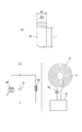
- FIG. 1 It is a perspective view which shows 1st Embodiment of the light emission type capsule treatment tool which concerns on this invention.
- (A) is a perspective view which shows the magnetic body which comprises the treatment tool
- (b) is explanatory drawing which shows schematic structure of the treatment tool. It is principal part expansion explanatory drawing of the treatment tool.
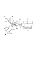
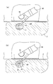
- (A) is explanatory drawing which shows the state which accommodated the treatment tool in the front-end
- (b) is explanatory drawing which shows the state which open
- (c) is the same treatment It is explanatory drawing which shows the state which locked the tool to the wall part in a body.
- This light-emitting capsule treatment tool is for irradiating light of a specific wavelength required for photoimmunotherapy.
- the light-emitting capsule therapeutic device 10 (hereinafter simply referred to as “therapeutic device 10”) of this embodiment is formed by winding a conducting wire 21, and an external power transmission antenna 70 (see FIG. 2).
- the power receiving coil 20 for receiving the power supplied through the magnetic flux from the magnetic field, the magnetic body 25 disposed on the inner periphery of the power receiving coil 20, and the power received from the power receiving coil 20 have a specific wavelength.
- a light emitter 30 that emits light and a capsule 35 that accommodates these are provided.
- the power receiving coil 20 in this embodiment is formed in a cylindrical shape by winding a conductive wire 21 (helical winding).
- the magnetic body 25 disposed on the inner periphery of the power receiving coil 20 is also cylindrical (see FIG. 2A).
- the conducting wire 21 that forms the power receiving coil 20 is wound from one end side in the axial direction (the lower end side in FIG. 1) of the magnetic body 25 toward the other end side in the axial direction. Is drawn out to one end side in the axial direction of the magnetic body 25 through the internal space of the magnetic body 25, and the other end is drawn out from the outer periphery of the other end side in the axial direction of the magnetic body 25.
- the conductive wires 21 are formed at a predetermined pitch, but the conductive wires 21 may be densely wound or multilayered, and are not particularly limited.
- the wire diameter of the conducting wire 21 is preferably 0.5 to 1.5 mm, and more preferably 0.8 to 1.2 mm.
- the outer diameter of the power receiving coil 20 is preferably 2.5 mm or less, and more preferably 2.0 mm or less.
- the axial length of the power receiving coil 20 is preferably 1 to 5 mm, and more preferably 2 to 3 mm.
- the length L of the cylindrical magnetic body 25 is preferably 3 to 6 mm, and more preferably 4 to 5 mm.
- the outer diameter D1 of the magnetic body 25 is preferably 2 mm or less, more preferably 1.8 mm or less, and the inner diameter D2 is preferably 1 mm or less, preferably 0.5 mm or less. .
- the magnetic body 25 of this embodiment has a cylindrical shape, but is not limited to a cylindrical shape, and may be a rectangular tube shape, a solid columnar shape, a rectangular column shape, or the like. However, as shown in FIG. 1, in the case where the wound conductive wire 21 is pulled out from one axial end side of the magnetic body 25 to the other axial end side, it is preferable to have a cylindrical shape.
- a ferromagnetic material such as ferrite, Fe, iron oxide, Cr oxide, Ni, amorphous, permalloy, or the like can be used.
- a light emitter 30 is disposed on one end side in the axial direction of the power receiving coil 20 coaxially with the axis of the power receiving coil 20 via a resonance capacitor 31. Both ends of the conducting wire 21 in the axial direction are connected.
- the light emitter 30 in this embodiment is a light emitting diode (LED). That is, as shown in FIG. 2B, the power receiving coil 20, the resonant capacitor 31, and the light emitter 30 are arranged in parallel, and the power receiving coil 20 is connected via the resonant capacitor 31 arranged in parallel.
- the light emitter 30 is a light emitting diode.
- the wavelength of light emitted by the illuminant 30 is selected such that the photosensitive material bound to the monoclonal antibody can absorb and cause a chemical change.
- IR700 phthalocyanine
- near infrared rays having a wavelength of 680 to 710 nm are employed.
- the power receiving coil 20, the magnetic body 25, the resonant capacitor 31, and the light emitting body 30 are accommodated in a capsule 35, whereby the treatment tool 10 can be inserted into and placed in the body.
- the capsule 35 in this embodiment is a resin molded product having a substantially capsule shape formed by coating the outer periphery of the power receiving coil 20, the magnetic body 25, the resonant capacitor 31, and the light emitting body 30 with a transparent resin material.
- the end on the light emitting body 30 side has a spherically rounded shape. A string-like body 50 to be described later is pulled out from the other end side of the capsule 35.
- the “capsule” in the present invention means a resin molded product having a capsule shape.
- the capsule for example, a capsule formed of a pair of containers having a cylindrical shape having a spherical end, or a capsule formed of a bottomed cylindrical container and a lid covering the same
- the receiving coil 20, the magnetic body 25, the resonance capacitor 31, and the like can be accommodated and covered so as not to be exposed outside the capsule.
- the outer diameter of the capsule 35 is preferably 3.0 mm or less, and more preferably 0.5 to 2.0 mm. Furthermore, the axial length of the capsule 35 is preferably 15 mm or less, and more preferably 3 mm or less. Further, as the material of the capsule 35, for example, epoxy resin, polycarbonate, acrylic resin, ABS resin or the like can be used, and the portion that accommodates the light emitter 30 weakens the intensity of light emitted from the light emitter 30. It is preferable that it is permeable. 4 and 6, the capsule 35 is omitted for convenience.
- the treatment tool 10 in this embodiment has a structure in which the light emitter 30 is coaxially connected to one axial end side of the power receiving coil 20, it is not limited to this structure.
- a light emitting capsule treatment device 10A (hereinafter referred to as “treatment”) in which light emitting bodies 30 are coaxially connected to both ends in the axial direction of the power receiving coil 20 via resonant capacitors 31, respectively. It may also be referred to as “tool 10A”.
- the light emitting body 30 and the resonance capacitor 31 are respectively arranged in the middle of the power receiving coil 20 in the axial direction (here, the center in the axial direction), and these are connected via the conducting wire 32. It is good also as the light emission type capsule treatment tool 10B (henceforth "the treatment tool 10B”) connected to the axial direction both ends.
- FIG.7 (c) the circuit diagram in the treatment tool 10A, 10B shown to FIG. 7 (a), (b) is shown by FIG.7 (c).
- FIG. 7C in these treatment devices 10 ⁇ / b> A and 10 ⁇ / b> B, the other light emitter 30 is reversed with respect to one light emitter 30 and connected in parallel to the resonance capacitor 31 and the power receiving coil 20. Has been. Therefore, when an alternating current is supplied to the power receiving coil 20 of the treatment devices 10A and 10B via a power transmission antenna 70 described later, the two light emitters 30 and 30 emit light alternately, so that the alternating current is efficiently used. Can be used.
- the power transmission antenna 70 of this embodiment has comprised the shape by which the conducting wire 71 was wound by planar spiral shape.
- the conducting wire 71 is wound so as to form a spiral shape in a plane at a predetermined interval (spiral winding), and forms an annular shape having a space in the center.
- a resonance capacitor 73 and an inverter circuit 75 are connected to the power transmission antenna 70. Then, when electric power supplied from a power source (not shown) is converted into an alternating current through the inverter circuit 75 and the alternating current is supplied to the power transmitting antenna 70 through the resonance capacitor 73, a magnetic field is generated in the power transmitting antenna 70. The magnetic flux is electromagnetically induced to the power receiving coil 20 of the treatment tool 10 and wirelessly fed (see FIG. 6).
- the outer diameter of the power transmission antenna 70 is 500 mm or less, and it is more preferable that it is 200 mm or less.
- the power transmission antenna 70 in this embodiment is arranged below the treatment subject, and the X-axis direction and the Y-axis are moved by a moving means (manipulator or the like) (not shown). It can move in the axial direction.
- the treatment tool 10 includes a locking portion that locks the capsule 35 at a target location in the body.
- the locking portion in this embodiment is a clip 40 that can grip a wall portion in the body.
- the clip 40 is slidably mounted on a pair of gripping pieces 41, 41 that can be opened and closed and normally biased in the opening direction, and to the outer periphery of the gripping pieces 41, 41, and slides toward the distal end side of the gripping piece 41.
- the slider 45 can be closed by closing the pair of grip pieces 41.
- the pair of gripping pieces 41, 41 are connected to each other at their base end sides via a connecting portion 41a, and their tip end sides are widened so as to be separated from each other, thereby forming a substantially C shape. It is so energized.
- the gripping piece 41 In the middle of each gripping piece 41 in the length direction, the gripping piece 41 has a shape bent outward through the step portion 41b, and the tip 41c of each gripping piece 41 has a claw shape bent inward.
- the connecting portion 41a is provided with a connecting portion 41d that can be attached to and detached from a later-described transport device 60 (see FIG. 4).
- the slider 45 has a circular ring shape, and is disposed on the base end side outer periphery of the pair of gripping pieces 41 and 41. Then, by sliding the slider 45 toward the distal end side of the gripping piece 41, the pair of gripping pieces 41, 41 are closed, and the tissue inside the body (for example, a tubular shape such as the large intestine) is formed by the claw-shaped tips 41c, 41c.
- the target location 1a) of the organ wall 1 can be grasped (see FIG. 4C).
- the shape of the clip is not limited to the above shape.
- another gripping piece may be provided between the pair of gripping pieces, as long as it can be closed by sliding the slider 45 and the body tissue can be gripped.
- the clip 40 constituting the locking portion is connected to the capsule 35 via a string-like body 50.
- the clip 40 is connected to the capsule 35 via the string-like body 50 so as to be on the other end side in the axial direction of the power receiving coil 20, that is, on the side opposite to the light emitting body 30 and the resonance capacitor 31. It has a structure.
- One end of the string-like body 50 is connected to the other axial end of the magnetic body 25, and the other end is connected to the slider 45 of the clip 40.
- the string-like body 50 of this embodiment is a twisted wire formed by twisting wires together.
- Examples of the string-like body 50 include a wire made of a synthetic resin such as polypropylene, nylon elastomer, polyether block amide, polyethylene, polylactic acid, polyester, polyetheretherketone, Ni—Ti, stainless steel, gold, titanium.
- Metal wires such as tantalum, platinum, iridium, and alloys thereof can be used. Among these, it is preferable to use polyester, nylon elastomer, polypropylene or the like having biocompatibility.
- the length of the string-like body 50 is preferably 15 mm or less, and more preferably 10 mm or less.
- the other end of the string-like body 50 is connected to the slider 45 of the clip 40.
- You may connect in the vicinity of the part 41b, and a connection location is not specifically limited.
- the transfer device 60 includes a cylindrical outer sheath 61, a cylindrical inner sheath 62 that is slidably inserted into the outer sheath 61, and a sheath holding member attached to the proximal end side of the inner sheath 62. Part 63.
- An operation wire 64 is slidably disposed in the inner sheath 62, and a chuck portion 64 a that allows the connection portion 41 d of the clip 40 to be attached and detached is provided at the distal end of the operation wire 64.
- a wire operation unit 65 is slidably disposed on the outer periphery of the sheath holding unit 63, and is connected to the proximal end side of the operation wire 64.
- the outer sheath 61 when the outer sheath 61 is slid back and forth in the axial direction of the sheath while holding the sheath holding portion 63, the outer sheath 61 slides relative to the inner sheath 62, and the sheath holding portion 63 is
- the wire operating portion 65 is held and slid back and forth in the axial direction of the sheath
- the operating wire 64 slides relative to the inner sheath 62.
- the inner sheath 62 may be held and the sheath holding part 63 may be slid, or the wire operation part 65 may be held and the sheath holding part 63 may be slid, and the operation method is not particularly limited.
- a conveying apparatus it is not limited to the said structure, What is necessary is just to be able to convey the treatment tool 10.
- the treatment tool 10 is locked to a predetermined portion 1 a of the wall portion 1 in the body via a clip 40 that is a locking portion, and is generated on the wall portion 1.
- the affected part C (for example, cancer cells) is irradiated with light.
- the body in this embodiment is specifically the large intestine, but the body is an organ other than the large intestine such as the stomach, and further, a tubular organ such as the duodenum, bile duct, pancreatic duct, etc. There is no particular limitation.
- the clip 40 is in a state where the slider 45 is positioned on the outer periphery on the proximal end side of the gripping piece 41 and the pair of gripping pieces 41 and 41 are opened.
- the outer sheath 61 is slid to the side opposite to the operator's hand side (hereinafter simply referred to as “sheath distal end side”) while holding the sheath holding portion 63 of the transfer device 60, and the distal end of the outer sheath 61 is moved.
- the portion is protruded from the tip of the inner sheath 62.
- the sheath holding portion 63 is held, the wire operation portion 65 is slid to the sheath distal end side, the operation wire 64 is pushed out, and the chuck portion 64 a is inserted from the distal end opening of the outer sheath 61.
- connection portion 41 d of the clip 40 is connected to the chuck portion 64 a of the operation wire 64.
- the sheath holding portion 63 of the transport device 60 is held, and the wire operation portion 65 is pulled toward the operator's hand side.
- the operation wire 64 is pulled and the clip 40 is pulled via the chuck portion 64a, the pair of expanded gripping pieces 41, 41 are drawn into the outer sheath 61 and pressed against the inner peripheral surface thereof. Therefore, as a result, the pair of gripping pieces 41 and 41 are closed against the elastic force, and the treatment instrument 10 is accommodated in the inner periphery of the distal end portion of the outer sheath 61 as shown in FIG.
- the treatment tool 10 is released from the distal end opening of the outer sheath 61, and the pair of gripping pieces 41, 41 of the clip 40 are opened as shown in FIG. Thereafter, the tips 41c, 41c of the pair of expanded gripping pieces 41, 41 are brought into contact with the target portion 1a of the wall portion 1, and in this state, the wire operation portion 65 is held, and the sheath holding portion 63 is moved. The inner sheath 62 is pushed out to the distal end side.
- the slider 45 of the clip 40 is pushed toward the gripping piece tip side by the tip of the inner sheath 62, and the pair of gripping pieces 41, 41 are closed and the state is maintained as shown in FIG. Therefore, the target location 1a of the wall 1 inside the body is sandwiched between the tips 41c, 41c of the pair of grip pieces 41, 41. Thereafter, the inner sheath 62 is pressed against the slider 45 (see the imaginary line in FIG. 3), and the wire operating portion 65 is pulled toward the hand side while restricting the movement of the slider 45, thereby connecting the chuck portion 64a and the clip 40. The connection with the part 41d is released (see FIG. 4C), and as shown in FIG. 6, only the treatment tool 10 and the treatment tool 10A are left in the body, and the transport device 60 can be pulled out from the body.
- the therapeutic device 10 and the therapeutic device 10 ⁇ / b> A can be locked to the target location 1 a of the wall 1 inside the body via the clip 40.
- the power transmission antenna 70 is installed under the treatment subject, and electric power is supplied to the power transmission antenna 70 from a power source (not shown). Then, the alternating current converted through the inverter circuit 75 is supplied to the conducting wire 71 of the power transmission antenna 70 through the resonance capacitor 73 to generate a magnetic field.
- the power receiving coil 20 is electromagnetically induced and wirelessly powered. And since the alternating current which the receiving coil 20 received is supplied to the light-emitting body 30, the light of a predetermined wavelength can be light-emitted.
- a specific wavelength of light which has conventionally only been irradiated from the outside of the body, is applied to the wall inside the body as shown in FIG. Since the affected part C generated in the part 1 can be irradiated with light having a specific wavelength from a closer position, it can be suitably used for photoimmunotherapy.
- the therapeutic devices 10 and 10A have a relatively simple configuration including the power receiving coil 20, the magnetic body 25, the light emitting body 30, and the capsule 35 that accommodates them, it is possible to make a small capsule shape. Become. Therefore, as described above, by swallowing through an endoscope (not shown), through a medical tube 95 (see FIG. 14) described later, a needle of a biopsy needle 91 (see FIG. 13), or the like, and from the mouth. (Refer FIG. 15), The treatment tools 10 and 10A can be easily arrange
- the capsule 35 is further provided with a locking portion (here, the clip 40) that locks the capsule 35 at a target location in the body. Therefore, as shown in FIG. 6, since the capsule 35 can be placed at a target location 1a in the body, light is irradiated effectively and in the necessary time in the vicinity of the affected part C to be treated. can do.
- a locking portion here, the clip 40
- the locking portion is slidably mounted on a pair of gripping pieces 41, 41 that can be opened and closed and normally biased in the opening direction, and the outer periphery of these gripping pieces 41, 41.
- It consists of a clip 40 having a slider 45 that can close the gripping piece 41 by sliding it toward the distal end side of the gripping piece 41. Therefore, in a state where the pair of gripping pieces 41, 41 are expanded, the tip portion thereof is brought into contact with the target portion 1a of the wall portion 1 in the body, and the slider 45 is slid to the tip side, thereby the pair of gripping pieces.
- the pieces 41 and 41 can be closed to hold the target portion 1a of the wall 1 inside the body.
- the capsule 35 can be easily locked to the wall portion 1 in the body via the clip 40, and the indwelling operation of the treatment devices 10 and 10A can be easily performed.
- the clip 40 which is a latching part is connected to the capsule 35 via the string-like body 50 (see FIG. 1), the latching part is a target location of the wall part 1 in the body.
- the capsule 35 is supported in the body via the string-like body 50 (see FIG. 6).
- the capsule 35 is supported so as to hang down via the string-like body 50, the light from the light emitting body 30 is hardly shielded and light can be irradiated to a distant place.
- the light emitting body 30 is disposed on one end side in the axial direction of the power receiving coil 20, and the clip 40 serving as a locking portion is disposed on the opposite side. Therefore, as shown in FIG. 6, when the subject 35 is lying on his / her back, if the capsule 35 is locked via the clip 40 at the location 1 a above the wall portion 1 in the body, the string-like body 50. Since the capsule 35 hangs down so that the light emitter 30 faces downward, it is possible to irradiate light from a position closer to the affected part C generated on the wall part 1 which is downward when facing up.
- the treatment tool 10A shown in FIG. 7A When the treatment tool 10A shown in FIG. 7A is suspended and supported via the clip 40 at a location 1a above the wall 1 in the body, as shown in FIG. Since the light emitters 30 and 30 can be brought close to the affected areas C and C generated above and below, the affected areas C and C can be more efficiently irradiated with light.
- the treatment tool 10B shown in FIG. 7B When the treatment tool 10B shown in FIG. 7B is suspended and supported via a clip 40 at a position above the wall 1 in the body, it is generated on the side in the circumferential direction of the wall 1 in the body. Since the light emitter 30 can be brought close to the affected area C, the affected area C can be efficiently irradiated with light.
- the power receiving coil 20 is connected to a light emitter 30 that is a light emitting diode via a resonant capacitor 31 arranged in parallel. Therefore, a simple circuit having the power receiving coil 20 and the resonance capacitor 31 can cause the light emitting diode forming the light emitter 30 to emit light, and the capsule 35 that accommodates them can be downsized.
- the power transmission antenna 70 has a shape in which a conducting wire 71 is wound in a planar spiral shape. Therefore, when AC power is supplied to the power transmission antenna 70, a strong magnetic field can be generated, and the power transmission antenna 70, as shown in FIG. Is moved in the X direction and / or Y direction by a moving means (not shown) to change the relative position between the power transmitting antenna 70 and the treatment device 10 or 10A, and the direction of the magnetic field emitted by the power transmitting antenna 70 and the treatment
- the power generation efficiency can be increased by matching the direction of the cylindrical axis of the power receiving coil 20 accommodated in the tools 10 and 10A, and light can be emitted from the light emitter 30 with sufficient intensity.
- FIG. 9 shows a second embodiment of the light emitting capsule treatment device according to the present invention. Note that substantially the same parts as those of the above-described embodiment are denoted by the same reference numerals, and description thereof is omitted.
- the light emitting capsule treatment device 10C of this embodiment (hereinafter referred to as “treatment device 10C”) is different from the embodiment in the structure of the locking portion. That is, the engaging part of the treatment tool 10C of this embodiment is configured such that the conductive wire 21 wound around the power receiving coil 20 is connected to the end of the power receiving coil 20 (here, the other axial end opposite to the light emitter 30). ), And is formed into a shape that can be pierced into tissue in the body.
- the light emitter 30 has a pair of lead wires 34, one lead wire 34 is connected to one end side in the axial direction of the power receiving coil 20, and the other lead wire 34 is inside the power receiving coil 20. It is pulled out from the space to the other end side in the axial direction, and is connected to the base end side of the puncture portion 33 via a silver solder 34a.
- the puncture portion 33 protrudes from the outer periphery of the capsule 35.
- the latching portion has a shape that allows the conducting wire 21 wound around the power receiving coil 20 to extend from the end of the power receiving coil 20 and pierce the tissue in the body. Accordingly, the power receiving coil 20 and the locking portion can be integrally formed, and the structure can be simplified and the manufacturing cost can be reduced.
- the light emitting capsule treatment device 10D (hereinafter referred to as “treatment device 10D”) of this embodiment has a stent 80 having a mesh-shaped opening 81 whose locking portion is locked to the inner periphery of the wall 1 inside the body. It has become. Then, the capsule 35 is directly connected to the stent 80 (see FIG. 10) or connected via a string-like body 50 (see FIG. 11).
- a plurality of capsules 35 arranged in the circumferential direction of the stent 80 are arranged in the axial direction.
- a plurality of capsules 35 are connected to one end side in the axial direction of the stent 80 via the string-like body 50, and one end side in the axial direction of the stent 80 faces upward.
- the plurality of capsules 35 hang down via the string-like body 50 and are arranged in the middle of the stent 80 in the axial direction.
- the locking portion is the stent 80 having the mesh-shaped opening 81, for example, using a stent placed in a tubular organ such as a bile duct or pancreatic duct,
- the treatment tool 10D can be placed at a predetermined location in the body.
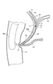
- FIG. 12 shows a fourth embodiment of the light emitting capsule treatment device according to the present invention. Note that substantially the same parts as those of the above-described embodiment are denoted by the same reference numerals, and description thereof is omitted.
- the locking portion is a tube stent 85 having an engaging means to the inner periphery of the wall 1 inside the body.
- the tube stent 85 has a tube shape in which both ends are open and a passage is provided inside, and flaps 86 and 86 are respectively provided at both ends in the axial direction.
- the flap 86 has a shape in which one end is connected to the tube stent 85 and the other end is curved and protrudes outward, and the flap 86 has a tubular organ such as the bile duct V2,
- the engaging means engages with the inner periphery of the wall portion 1 of other tissue.
- the capsule 35 is connected to one end side of the tube stent 85 (the end portion in the insertion direction inside the body) via the string-like body 50. Note that the capsule 35 may be directly connected to the tube stent 85.
- the tube stent 85 can be placed in the bile duct V2, for example, as shown in FIG.
- the bile duct V2 extends from the nipple N provided at the lower part of the duodenum V1, and the pancreatic duct V3 also branches from the nipple N and extends.
- the tube stent 85 is inserted through, for example, an endoscope (not shown), one end side thereof is disposed in the back direction of the bile duct V2, and the flap 86 as the engaging means is provided in the vicinity of the entrance of the nipple N.
- the tube stent 85 can be placed in the bile duct V2.
- the capsule 35 is connected to the one end side of the tube stent via the string-like body 50, light of a specific wavelength can be efficiently irradiated from the back of the affected part C.
- the tube stent 85 can be placed and the tube stent 85 can be placed.
- a passage can be secured in the interior.
- FIG. 13 shows a fifth embodiment of the light emitting capsule treatment device according to the present invention. Note that substantially the same parts as those of the above-described embodiment are denoted by the same reference numerals, and description thereof is omitted.
- treatment device 10F has a size and shape that allows the capsule 35 (see FIG. 13B) to pass through the needle of the biopsy needle 91.
- the treatment tool 10F is applied to a biopsy needle 91 protruding from the distal end opening of the ultrasonic endoscope 90. It is not limited to only biopsy needles.
- an ultrasonic probe (probe) 92 for ultrasonic irradiation and detection is provided at the tip of the ultrasonic endoscope 90.
- the ultrasonic endoscope 90 is inserted from the mouth, the distal end portion thereof is arranged inside the stomach, and the ultrasonic probe 92 is irradiated with ultrasonic waves from the inner surface side of the stomach wall portion 1 to be adjacent.
- the target affected part C where the therapeutic device 10F is to be placed is detected. Thereafter, as shown in FIG.
- the biopsy needle 91 is projected from the distal end opening of the ultrasonic endoscope 90, penetrates through the stomach wall 1, and is exposed to the affected part C of the organ Z such as the pancreas.
- the meter reading 91 is punctured.
- the therapeutic instrument 10F is placed in the affected area C through the inside of the biopsy needle 91 by a tube, a sheath, a pusher or the like (not shown).
- the capsule 35 since the capsule 35 is sized and shaped so that it can pass through the needle of the biopsy needle 91, for example, from the distal end opening of the ultrasonic endoscope, the capsule 35 The needle can be protruded and inserted into the affected area C of the organ Z in need of treatment, and then the capsule 35 can be injected into the affected area C through the inside of the needle of the biopsy needle 91.
- the organ 35 such as the pancreas can be placed in the affected part C of the organ Z such as the pancreas to be treated so as to be embedded in the capsule 35 and difficult to place with the clip 40 or the stent 80 or the like.
- the treatment tool 10F can be appropriately placed also in the affected area C (effect of claim 8).
- the organ Z in which the treatment tool 10F is placed in this embodiment may be other than the pancreas, and is not particularly limited.
- FIG. 14 shows a sixth embodiment of the light emitting capsule treatment device according to the present invention. Note that substantially the same parts as those of the above-described embodiment are denoted by the same reference numerals, and description thereof is omitted.
- the engaging portion is inserted from the distal end opening of the endoscope 90A and inserted into a predetermined position of the tubular organ. It becomes the medical tube 95 indwelling.
- the capsule 35 is directly connected to the distal end side of the medical tube 95.
- the capsule 35 may be connected to the distal end side of the medical tube 95 via the string-like body 50.
- the treatment tool 10G of this embodiment irradiates light to the affected part C generated on the wall part 1 around the branch part B, which has branch pipes V4 and V5 extending from the back side of the bile duct V2, for example. Therefore, it can be used suitably.
- the medical tube 95 is inserted into the bile duct V2 through the nipple N through the guide wire G, and the distal end portion is branched to the branch portion B.
- the capsules 35 are arranged by arranging them in the above. While maintaining this state, it is possible to irradiate the affected part C generated on the wall part 1 around the branch part B from the light emitter 30.
- the locking portion is the medical tube 95 that is inserted through the distal end opening of the endoscope 90A and inserted into a predetermined position of the tubular organ, the endoscope 90A.
- the therapeutic device 10F can be placed in a place where it is difficult to place a place such as the bifurcation B of a tubular organ such as the bile duct V2 or the pancreatic duct V3. Can be irradiated.
- FIG. 15 shows a seventh embodiment of the light emitting capsule treatment device according to the present invention. Note that substantially the same parts as those of the above-described embodiment are denoted by the same reference numerals, and description thereof is omitted.
- treatment device 10H has a structure that does not have a locking portion.
- the treatment tool 10H has a built-in camera (not shown) or is provided with a radiopaque marker on a part of the capsule 35 so that the position of the treatment tool 10H can be confirmed from the outside. Is provided.
- the capsule 35 is swallowed from the mouth, the treatment tool 10H is grasped by the image by the camera, the image under fluoroscopy, etc., and the affected part generated on the wall 1 in the body
- the therapeutic instrument 10H reaches the vicinity of C, light can be emitted from the light emitter 30 via the power transmission antenna 70.
- Luminescent capsule treatment device 20 Power-receiving coil 21 Conductor 25 Magnetic body 30 Light-emitting body 31 Resonant capacitor 35 Capsule 40 Clip 41 Holding piece 45 Slider 50 String-like body 60 Transfer device 70 Power transmission antenna 80 Stent 81 Opening 85 Tube stent 90 Ultrasound endoscope 90A Endoscope 91 Biopsy needle 95 Medical tube
Landscapes
- Health & Medical Sciences (AREA)
- Engineering & Computer Science (AREA)
- Biomedical Technology (AREA)
- Life Sciences & Earth Sciences (AREA)
- Veterinary Medicine (AREA)
- Public Health (AREA)
- General Health & Medical Sciences (AREA)
- Animal Behavior & Ethology (AREA)
- Pathology (AREA)
- Radiology & Medical Imaging (AREA)
- Nuclear Medicine, Radiotherapy & Molecular Imaging (AREA)
- Biophysics (AREA)
- General Engineering & Computer Science (AREA)
- Power Engineering (AREA)
- Pulmonology (AREA)
- Anesthesiology (AREA)
- Heart & Thoracic Surgery (AREA)
- Hematology (AREA)
- Radiation-Therapy Devices (AREA)
- Surgical Instruments (AREA)
- Media Introduction/Drainage Providing Device (AREA)
Abstract
がん組織等の患部に、特定波長の光をより近接した位置から照射することができる、発光型カプセル治療具を提供する。この発光型カプセル治療具10は、光免疫療法に必要とされる特定波長の光を照射するためのものであって、導線21を巻回して形成されて、外部の送電アンテナ70から磁束を媒介して供給される電力を受電するための、受電コイル20と、該受電コイル20の内周に配置された磁性体と、受電コイル20から電力が供給されて特定波長の光を発光する発光体30と、これらを収容するカプセルとを備えている。
Description
本発明は、光免疫療法に必要とされる特定波長の光を照射するための、発光型カプセル治療具に関する。
近年、がん治療法として、正常組織を損傷することなく、腫瘍細胞を選択的に破壊する方法として、光免疫療法が注目されている。この光免疫療法によるがん治療のメカニズムは、次の通りである。
通常、がん細胞の周囲にも、がん細胞を破壊する免疫細胞(キラーT細胞)が存在するが、がん細胞を取り巻く免疫抑制細胞によって、キラーT細胞の作用が抑制されている。そこで、がん細胞やがん細胞の周囲に存在する免疫抑制細胞の表面にある特異的タンパク質を認識するモノクローナル抗体(MAb)と、特定の波長(例えば近赤外線)の光を吸収して化学反応を起こし、発熱等によって細胞を破壊する作用を有する感光物質とを結合させ、この感光物質が結合したモノクローナル抗体を体内に投与することにより、モノクローナル抗体を介して感光物質をがん細胞やその周囲に存在する免疫抑制細胞の表面に特異的に付着させ、その状態で感光物質が反応する波長の光を照射して、感光物質に化学変化を起こさせ、感光物質が付着したがん細胞や免疫抑制細胞を破壊するというものである。感光物質としては、例えば、近赤外線を吸収して発熱するIR700(フタロシアンニン)が用いられている。
上記のような治療に用いられる光照射装置として、例えば、下記特許文献1には、光線力学療法/光線温熱療法/光線温熱化学療法において、810nmの波長の光を照射する光照射手段を備えた、医療装置が開示されている。その実施形態には、6個のLEDを有する光照射部を備え、体外から810nmの波長の近赤外線を照射することが記載されている。
上記特許文献1に記載されているように、特定波長の近赤外線を体外から照射するようにした場合、この近赤外線は、人体の組織に対してある程度の透過性があるので、外部からの照射でも治療を行える場合もある。しかしながら、厚い皮下脂肪などの組織に覆われた患部には、光が効果的に届かず、治療効果を高められないという問題があった。
したがって、本発明の目的は、がん組織等の患部に、特定波長の光をより近接した位置から照射することができる、発光型カプセル治療具を提供することにある。
上記目的を達成するため、本発明に係る発光型カプセル治療具は、光免疫療法に必要とされる特定波長の光を照射するためのものであって、導線を巻回して形成されて、外部の送電アンテナから磁束を媒介して供給される電力を受電するための、受電コイルと、該受電コイルの内周に配置された磁性体と、前記受電コイルから電力が供給されて前記特定波長の光を発光する発光体と、これらを収容するカプセルとを備えていることを特徴とする。
本発明によれば、受電コイルと磁性体と発光体とこれらを収容するカプセルとを備えた比較的簡単な構成からなるので、小さいカプセル形状にすることが可能である。このため、例えば、内視鏡や、医療用チューブ、生検針の針などを通して、或いは、口から飲み込むことにより、体内の治療が必要とされる箇所に治療具を容易に配置することができる。
そして、外部の送電アンテナに交流電流を流し、電磁誘導により、受電コイルに電力を供給すると、受電コイルから供給された電力によって、発光体から光免疫療法に必要とされる特定波長の光を発光させることができる。そのため、例えば、がん組織などの治療が必要な箇所に、光をより近接した位置から照射することができ、光免疫療法に好適に使用することができる。
以下、図1~8を参照して、本発明に係る発光型カプセル治療具の、第1実施形態について説明する。
この発光型カプセル治療具は、光免疫療法に必要とされる特定波長の光を照射するためのものである。図1に示すように、この実施形態の発光型カプセル治療具10(以下、単に「治療具10」という)は、導線21を巻回して形成されて、外部の送電アンテナ70(図2参照)から磁束を媒介して供給される電力を受電するための、受電コイル20と、この受電コイル20の内周に配置された磁性体25と、受電コイル20から電力が供給されて、特定波長の光を発光する発光体30と、これらを収容するカプセル35とを備えている。
図1に示すように、この実施形態における受電コイル20は、導線21を巻回(ヘリカル巻)して、円筒状に形成されている。この受電コイル20の内周に配置された磁性体25も、円筒状をなしている(図2(a)参照)。
また、図1に示すように、受電コイル20を形成する導線21は、磁性体25の軸方向一端側(図1中の下端側)から軸方向他端側へ向けて巻回され、その一端は、磁性体25の内部空間を通して、磁性体25の軸方向一端側へ引き出されており、他端は、磁性体25の軸方向他端側外周から引き出されている。
なお、図1の実施形態では、導線21が所定ピッチで形成されているが、導線21は密巻きにしたり、多層巻としたりしてもよく、特に限定はされない。また、導線21の線径は、0.5~1.5mmであることが好ましく、0.8~1.2mmであることがより好ましい。また、受電コイル20の外径は、2.5mm以下であることが好ましく、2.0mm以下であることがより好ましい。更に、受電コイル20の軸方向長さは、1~5mmであることが好ましく、2~3mmであることがより好ましい。
また、図2(a)に示すように、円筒状をなした磁性体25は、その長さLが、3~6mmであることが好ましく、4~5mmであることがより好ましい。更に磁性体25の外径D1は、2mm以下であることが好ましく、1.8mm以下であることがより好ましく、内径D2は、1mm以下であることが好ましく、0.5mm以下であることが好ましい。
なお、この実施形態の磁性体25は円筒状をなしているが、円筒状のみならず、角筒状や、中実の円柱状・角柱状等であってもよく、特に限定はされない。ただし、図1に示すように、巻回した導線21を、磁性体25の軸方向一端側から軸方向他端側へ引き出す場合には、筒状をなしていることが好ましい。また、磁性体25の材料としては、例えば、フェライトや、Fe、酸化鉄、酸化Cr、Ni、アモルファス、パーマロイ等の強磁性材料を用いることができる。
また、図1に示すように、受電コイル20の軸方向一端側に、同受電コイル20の軸心に対して同軸的に、共振コンデンサ31を介して発光体30が配置されており、これらに導線21の軸方向両端が接続されている。なお、この実施形態における発光体30は、発光ダイオード(LED)である。すなわち、図2(b)に示すように、受電コイル20と、共振コンデンサ31と、発光体30とが並列して配置されており、受電コイル20は、並列配置された共振コンデンサ31を介して、発光ダイオードをなす発光体30に接続されている。
なお、発光体30により発光する光の波長は、モノクローナル抗体に結合される感光物質が吸収して化学変化を起こすことが可能な波長を選択する。例えば、感光物質としてIR700(フタロシアンニン)を用いる場合には、波長680~710nmの近赤外線が採用される。
上記の受電コイル20や、磁性体25、共振コンデンサ31、発光体30は、カプセル35に収容されており、それによって治療具10は、体内への挿入や留置が可能となっている。この実施形態におけるカプセル35は、受電コイル20や、磁性体25、共振コンデンサ31、発光体30の外周を、透過性の樹脂材料によってコーティングして形成された、略カプセル形状をなした樹脂成型品となっており、発光体30側の端部は球状に丸みを帯びた形状をなしている。なお、後述する紐状体50は、カプセル35の他端側から引き出されている。
上記のように、本発明における「カプセル」とは、カプセル形状をなした樹脂成型品を含む意味である。ただし、カプセルとしては、例えば、球状端部を有する筒状をなした一対の容器からなるカプセル形状をなしたものや、有底筒状の容器及びそれを覆う蓋体からなるカプセル形状をなしたもの、等としてもよく、受電コイル20や、磁性体25、共振コンデンサ31等を収容して、カプセル外部に露出しないようにカバーすることができれば、特に限定はされない。
また、カプセル35の外径は、3.0mm以下であることが好ましく、0.5~2.0mmであることがより好ましい。更に、カプセル35の軸方向長さは、15mm以下であることが好ましく、3mm以下であることがより好ましい。また、カプセル35の材料としては、例えば、エポキシ樹脂や、ポリカーボネート、アクリル樹脂、ABS樹脂等を用いることができ、発光体30を収容する部分は、発光体30から発光される光の強度を弱めないように、透過性のあるものであることが好ましい。なお、図4及び図6においては、便宜上、カプセル35を省略している。
また、この実施形態における治療具10は、受電コイル20の軸方向一端側に同軸的に発光体30が接続された構造となっているが、この構造に限定されるものではない。例えば、図7(a)に示すように、受電コイル20の軸方向両端側に、共振コンデンサ31を介して発光体30をそれぞれ同軸的に接続した、発光型カプセル治療具10A(以下、「治療具10A」という)としてもよい。更に図7(b)に示すように、受電コイル20の軸方向途中(ここでは軸方向中央)に、発光体30及び共振コンデンサ31をそれぞれ配置して、これらを導線32を介して受電コイル20の軸方向両端側に接続した、発光型カプセル治療具10B(以下、「治療具10B」という)としてもよい。
なお、図7(c)には、図7(a),(b)に示す治療具10A,10Bにおける回路図が示されている。この図7(c)に示すように、これらの治療具10A,10Bにおいては、一方の発光体30に対して他方の発光体30を逆向きにして、共振コンデンサ31及び受電コイル20に並列接続されている。そのため、後述する送電アンテナ70を介して、治療具10A,10Bの受電コイル20に交流電流が供給されると、2つの発光体30,30が交互に発光することになるので、交流電流を効率的に利用することができる。
上記構造をなした治療具10の発光体30へは、外部の送電アンテナ70から電力が供給されるようになっている。図2(b)に示すように、この実施形態の送電アンテナ70は、導線71が平面渦巻形状に巻かれた形状をなしている。ここでは、導線71を、所定間隔をあけて、平面的に渦巻形状をなすように巻かれており(スパイラル巻)、中央に空所を有する円環状をなしている。
また、この送電アンテナ70には、共振コンデンサ73と、インバータ回路75とが接続されている。そして、図示しない電源から供給された電力が、インバータ回路75を介して交流電流に変換され、該交流電流が共振コンデンサ73を通して送電アンテナ70に供給されると、送電アンテナ70に磁界が発生して、その磁束が、治療具10の受電コイル20へと電磁誘導されて無線給電されるようになっている(図6参照)。
なお、送電アンテナ70の外径は、500mm以下であることが好ましく、200mm以下であることがより好ましい。
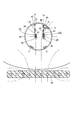
図5に示すように、この実施形態における送電アンテナ70は、治療対象者の下方に配置されるようになっており、また、図示しない移動手段(マニュピュレーター等)によって、X軸方向及びY軸方向に移動可能となっている。
更に、この治療具10においては、カプセル35を、体内の目的とする箇所に係止させる係止部を備えている。
図1、図3及び図4に示すように、この実施形態における係止部は、体内の壁部を把持可能なクリップ40となっている。このクリップ40は、開閉可能で常時は開く方向に付勢された一対の把持片41,41と、これらの把持片41,41の外周にスライド可能に装着され、把持片41の先端側にスライドさせることにより、一対の把持片41,41を閉じさせることができるスライダ45とを有している。
詳述すると、一対の把持片41,41は、その基端側どうしが連結部41aを介して互いに連結されており、その先端側が互いに離れるように拡開して、略ハの字状をなすように付勢されている。各把持片41の長さ方向途中は、段部41bを介して外向きに屈曲した形状をなしており、また、各把持片41の先端41cは、内側に屈曲した爪状をなしている。更に、前記連結部41aには、後述する搬送装置60(図4参照)に着脱可能とされた接続部41dが設けられている。
一方、スライダ45は、円形リング状をなしており、一対の把持片41,41の基端側外周に配置されている。そして、スライダ45を把持片41の先端側にスライドさせるこにより、一対の把持片41,41を閉じさせて、爪状をなした先端41c,41cによって、体内の組織(例えば、大腸等の管状器官の壁部1の、目的の箇所1a)を把持可能となっている(図4(c)参照)。
なお、クリップの形状としては、上記形状に限定されるものではない。例えば、一対の把持片の間に、更に別の把持片を設けてもよく、スライダ45のスライドにより閉じて、体内組織を把持可能であればよい。
また、図1及び図3に示すように、係止部を構成するクリップ40は、紐状体50を介して前記カプセル35に連結されている。この実施形態では、受電コイル20の軸方向他端側、すなわち、前記発光体30や共振コンデンサ31とは反対側となるように、紐状体50を介してカプセル35にクリップ40が連結された構造となっている。この紐状体50は、その一端が前記磁性体25の軸方向他端側に連結されており、他端が前記クリップ40のスライダ45に連結されている。また、この実施形態の紐状体50は、線材を捩り合わせて形成された捩り線となっている。
上記紐状体50としては、例えば、ポリプロピレン、ナイロンエラストマー、ポリエーテルブロックアミド、ポリエチレン、ポリ乳酸、ポリエステル、ポリエーテルエーテルケトン等の合成樹脂からなる線材や、Ni-Tiや、ステンレス、金、チタン、タンタル、白金、イリジウムや、それらの合金等の金属線材を用いることができる。その中でも、生体適合性を有する、ポリエステル、ナイロンエラストマー、ポリプロピレン等を用いることが好ましい。
また、紐状体50の長さは、15mm以下であることが好ましく、10mm以下であることがより好ましい。
なお、この実施形態では、紐状体50の他端は、クリップ40のスライダ45に連結されているが、図8に示すように、クリップ40を構成する把持片41の軸方向途中の、段部41bの近傍に連結してもよく、連結箇所は特に限定されない。
次に、上記構造をなした治療具10を体内の所定箇所まで搬送する、搬送装置60について、図4を参照して説明する。この搬送装置60は、筒状のアウターシース61と、該アウターシース61内にスライド可能に挿入配置された筒状のインナーシース62と、該インナーシース62の基端側に取付されられたシース保持部63とを有している。インナーシース62内には、操作ワイヤ64がスライド可能に配置されており、該操作ワイヤ64の先端には、前記クリップ40の接続部41dを着脱可能とするチャック部64aが設けられている。また、前記シース保持部63の外周には、ワイヤ操作部65がスライド可能に配置されており、これが前記操作ワイヤ64の基端側に連結されている。
そして、例えば、シース保持部63を保持して、アウターシース61をシースの軸方向前後にスライドさせると、インナーシース62に対してアウターシース61が相対的にスライドし、また、シース保持部63を保持して、ワイヤ操作部65をシースの軸方向前後にスライドさせると、インナーシース62に対して操作ワイヤ64が相対的にスライドするようになっている。なお、インナーシース62を保持して、シース保持部63をスライドさせたり、ワイヤ操作部65を保持して、シース保持部63をスライドさせたりしてもよく、操作方法に特に限定はない。また、搬送装置としては、上記構造のものに限定されず、治療具10を搬送可能であればよい。
次に、上記構成からなる本発明に係る治療具10の、使用方法の一例について説明する。なお、この使用方法は一例であり、特に限定はされない。
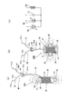
図6に示すように、この実施形態では、体内の壁部1の所定の箇所1aに、係止部であるクリップ40を介して、治療具10を係止させて、壁部1に生成された患部C(例えば、がん細胞)に、光を照射させるものである。この実施形態における体内とは、具体的には大腸とされているが、体内としては、大腸以外にも、胃等の臓器や、更には、十二指腸や胆管、膵管等の管状器官等であってもよく、特に限定はされない。
まず、クリップ40は、図1や図3に示すように、スライダ45を把持片41の基端側外周に位置させて、一対の把持片41,41を開いた状態とする。
また、搬送装置60のシース保持部63を保持して、アウターシース61を、操作者の手元側とは反対側(以下、単に「シース先端側」という)にスライドさせて、アウターシース61の先端部を、インナーシース62の先端部よりも突出させておく。更に、シース保持部63を保持して、ワイヤ操作部65をシース先端側にスライドさせて、操作ワイヤ64を押し出して、アウターシース61の先端開口からチャック部64aを挿出させておく。
そして、図3に示すように、クリップ40の接続部41dを、操作ワイヤ64のチャック部64aに接続させる。この状態で、搬送装置60のシース保持部63を保持して、ワイヤ操作部65を、操作者の手元側に引っ張る。すると、操作ワイヤ64が引っ張られて、チャック部64aを介してクリップ40が引っ張られるので、拡開した一対の把持片41,41が、アウターシース61内に引き込まれて、その内周面に押圧されるため、その結果、弾性力に抗して一対の把持片41,41が閉じて、図4(a)に示すように、アウターシース61の先端部内周に治療具10が収容される。
そして、図5に示すように、仰向けで寝た治療対象者の口から、図示しない内視鏡を挿入して、その先端部を体内の所定位置まで移動させた後、同内視鏡のルーメンを通じて、治療具10を収容した搬送装置60全体を移動させていき、その先端部を、体内の壁部1の目的位置の、やや手前に至る位置まで移動させる。次いで、搬送装置60のシース保持部63を保持して、アウターシース61を操作者の手元側にスライドさせる(図4(a)の矢印参照)。それによって、アウターシース61の先端開口から治療具10が開放されて、図4(b)に示すように、クリップ40の一対の把持片41,41が開く。その後、拡開した一対の把持片41,41の先端41c,41cを、壁部1の目的の箇所1aに当接させ、その状態で、ワイヤ操作部65を保持して、シース保持部63を介してインナーシース62を先端側に押し出す。
すると、インナーシース62の先端によって、クリップ40のスライダ45が把持片先端側に押されて、図4(c)に示すように、一対の把持片41,41が閉じて、その状態が維持されるので、一対の把持片41,41の先端41c,41cによって、体内の壁部1の目的の箇所1aが挟持される。その後、インナーシース62をスライダ45に押し当てて(図3の想像線参照)、スライダ45の移動を規制しつつ、ワイヤ操作部65を手元側に引っ張ることで、チャック部64aとクリップ40の接続部41dとの接続が解除されて(図4(c)参照)、図6に示すように、治療具10や治療具10Aのみを体内に残して、搬送装置60を体内から引き抜くことができる。
以上のようにして、図6に示すように、体内の壁部1の目的の箇所1aに、クリップ40を介して治療具10や治療具10Aを係止させることができる。そして、図5に示すように、治療対象者の下方に送電アンテナ70を設置して、同送電アンテナ70に図示しない電源から電力を供給する。すると、インバータ回路75を介して変換された交流電流が、共振コンデンサ73を通して、送電アンテナ70の導線71に供給されて磁界が発生して、図6に示すように、その磁束が、治療具10の受電コイル20へと電磁誘導されて無線給電される。そして、受電コイル20が受電した交流電流が、発光体30へ供給されるので、所定波長の光を発光させることができる。
このとき、光免疫療法において特定波長の光を照射する際に、従来は体外から照射するしかなかった特定波長の光を、この治療具10,10Aでは、図6に示すように、体内の壁部1に生成された患部Cに、特定波長の光を、より近接した位置から照射することができるので、光免疫療法に好適に使用することができる。
また、この治療具10,10Aは、受電コイル20と磁性体25と発光体30とこれらを収容するカプセル35とを備えた比較的簡単な構成からなるので、小さいカプセル形状にすることが可能となる。そのため、上述したように、図示しない内視鏡を介して、または、後述する医療用チューブ95(図14参照)、生検針91の針(図13参照)などを通して、更には口から飲み込むことによって(図15参照)、体内の治療が必要とされる箇所に、治療具10,10Aを容易に配置することができる。
更に、この実施形態においては、カプセル35を、体内の目的とする箇所に係止させる係止部(ここではクリップ40)を更に備えている。そのため、図6に示すように、カプセル35を、体内の目的の箇所1aに留置することができるので、治療すべき患部Cの近傍にて、光を効果的にかつ必要とされる時間で照射することができる。
また、この実施形態においては、係止部は、開閉可能で常時は開く方向に付勢された一対の把持片41,41と、これらの把持片41,41の外周にスライド可能に装着され、把持片41の先端側にスライドさせることにより、把持片41を閉じさせることができるスライダ45とを有する、クリップ40からなる。そのため、一対の把持片41,41を拡開させた状態で、その先端部を体内の壁部1の目的の箇所1aに当接させ、スライダ45を先端側にスライドさせることにより、一対の把持片41,41を閉じさせて、体内の壁部1の目的の箇所1aを挟持させることができる。このように、体内の壁部1にクリップ40を介して、カプセル35を簡単に係止させることができ、治療具10,10Aの留置作業を容易に行うことができる。
更にこの実施形態においては、係止部であるクリップ40は、カプセル35に紐状体50を介して連結されているので(図1参照)、係止部を体内の壁部1の目的の箇所1aに係止させると、紐状体50を介してカプセル35が体内に支持される(図6参照)。このとき、カプセル35は、紐状体50を介して垂れ下がるように支持されるので、発光体30からの光が遮蔽されにくくして、遠い箇所にも光を照射することができる。
なお、この実施形態の治療具10は、受電コイル20の軸方向一端側に発光体30が配置され、その反対側に係止部であるクリップ40が配置されている。そのため、図6に示すように、治療対象者が仰向けで寝たときに、体内の壁部1の上方となる箇所1aに、カプセル35をクリップ40を介して係止させると、紐状体50を介して、発光体30が下向きとなるように、カプセル35が垂れ下がるので、仰向け時に下方となる壁部1に生成された患部Cに、より近接させた位置から光を照射することができる。
また、図7(a)に示す治療具10Aを、体内の壁部1の上方の箇所1aにクリップ40を介して吊り下げ支持させたときには、図6に示すように、体内の壁部1の上方及び下方に生成された患部C,Cに、発光体30,30をそれぞれ近接させることができるので、それらの患部C,Cに、より効率的に光を照射することができる。なお、図7(b)に示す治療具10Bを、体内の壁部1の上方の箇所にクリップ40を介して吊り下げ支持させたときには、体内の壁部1の周方向側方に生成された患部Cに、発光体30を近接させることができるので、その患部Cに効率的に光を照射することができる。
また、この実施形態においては、図1や図2(b)に示すように、受電コイル20は、並列配置された共振コンデンサ31を介して、発光ダイオードをなす発光体30に接続されている。そのため、受電コイル20と共振コンデンサ31とを有するシンプルな回路で、発光体30をなす発光ダイオードを発光させることができ、それらを収容するカプセル35の小型化を図ることができる。
更に、この実施形態においては、図2(b)に示すように、送電アンテナ70は、導線71が平面渦巻形状に巻かれた形状をなしている。そのため、送電アンテナ70に交流電力を通電したときに、強い磁界を発生させることができ、治療具10や治療具10Aがどのような姿勢にあっても、図5に示すように、送電アンテナ70を図示しない移動手段によって、X方向及び/又はY方向に移動させて、送電アンテナ70と治療具10,10Aとの相対位置を変えることで、送電アンテナ70によって発散される磁場の方向と、治療具10,10Aに収容された受電コイル20の筒軸の方向とを一致させて、発電効率を高めることができ、発光体30から十分な強度で光を照射することができる。
図9には、本発明に係る発光型カプセル治療具の、第2実施形態が示されている。なお、前記実施形態と実質的に同一部分には同符号を付してその説明を省略する。
この実施形態の発光型カプセル治療具10C(以下、「治療具10C」という)は、前記実施形態と係止部の構造が異なっている。すなわち、この実施形態の治療具10Cの係止部は、受電コイル20に巻回された導線21を、同受電コイル20の端部(ここでは発光体30とは反対側の軸方向他端側)から延出させて、体内の組織に突き刺し可能な形状に付形させた、穿刺部33からなっている。また、発光体30は一対のリード線34,34を有しており、一方のリード線34が、受電コイル20の軸方向一端側に接続され、他方のリード線34は、受電コイル20の内部空間から軸方向他端側に引き出されて、前記穿刺部33の基端側に、銀ロウ34aを介して接続されている。なお、前記穿刺部33は、カプセル35の外周から突出されている。
そして、この実施形態の治療具10Cによれば、係止部は、受電コイル20に巻回された導線21を、受電コイル20の端部から延出させて、体内の組織に突き刺し可能な形状に付形させた穿刺部33からなるので、受電コイル20と係止部とを一体的に形成することができ、構造を簡単にして製造コストも低減することができる。
図10及び図11には、本発明に係る発光型カプセル治療具の、第3実施形態が示されている。なお、前記実施形態と実質的に同一部分には同符号を付してその説明を省略する。
この実施形態の発光型カプセル治療具10D(以下、「治療具10D」という)は、その係止部が、体内の壁部1の内周に係止する、メッシュ状の開口81を有するステント80となっている。そして、このステント80に、カプセル35が直接連結されているか(図10参照)、または、紐状体50を介して連結されている(図11参照)。
図10に示す治療具10Dの場合は、ステント80の周方向に配置された複数のカプセル35が、軸方向に沿って複数配列されている。一方、図11に示す治療具10Dの場合は、ステント80の軸方向一端側に、紐状体50を介して複数のカプセル35が連結されており、ステント80の軸方向一端側が上向きとなったときに、複数のカプセル35が、紐状体50を介して垂れ下がって、ステント80の軸方向途中位置に配置されるようになっている。
なお、ステント80としては、例えば、金属円筒をレーザー加工やエッチング等によりメッシュ状の開口81を形成したものや、或いは、金属線材を編んだり組んだり絡ませたりして、メッシュ状の開口81を有する筒状に形成したものでもよく、特に限定はされない。
そして、この実施形態の治療具10Dによれば、係止部がメッシュ状の開口81を有するステント80であるので、例えば、胆管や膵管等の管状器官内に留置されるステントを利用して、治療具10Dを体内の所定箇所に留置することができる。
図12には、本発明に係る発光型カプセル治療具の、第4実施形態が示されている。なお、前記実施形態と実質的に同一部分には同符号を付してその説明を省略する。
この実施形態の発光型カプセル治療具10E(以下、「治療具10E」という)は、その係止部が、体内の壁部1の内周への係合手段を有するチューブステント85となっている。このチューブステント85は、両端が開口して内部に通路を設けたチューブ状をなしており、その軸方向両端にフラップ86,86がそれぞれ設けられている。
前記フラップ86は、その一端がチューブステント85に連結され、他端が湾曲して外方に突出した自由端とされた形状となっており、該フラップ86が、胆管V2等の管状器官や、その他の組織の壁部1の内周に係合する係合手段をなしている。また、チューブステント85の一端側(体内への挿入方向奥方の端部)に、紐状体50を介してカプセル35が連結されている。なお、カプセル35は、チューブステント85に直接連結してもよい。
このチューブステント85は、図12に示すように、例えば、胆管V2に留置することができる。この胆管V2は、十二指腸V1の下部に設けられた乳頭Nから伸びておりおり、また、乳頭Nからは膵管V3も分岐して伸びている。
そして、チューブステント85を、例えば、図示しない内視鏡を介して挿入していき、その一端側を、胆管V2の奥方向に配置し、係合手段であるフラップ86を乳頭Nの入口近傍に係止させることで、胆管V2にチューブステント85を留置することができる。このとき、チューブステントの一端側に紐状体50を介してカプセル35が連結されているので、患部Cの奥方から特定波長の光を効率的に照射することができる。
このように、この実施形態の治療具10Eにおいては、例えば、胆管V2や膵管V3等の管状器官内に留置することによって、同チューブステント85を利用して留置することができると共に、チューブステント85の内部に通路を確保することができる。
図13には、本発明に係る発光型カプセル治療具の、第5実施形態が示されている。なお、前記実施形態と実質的に同一部分には同符号を付してその説明を省略する。
この実施形態の発光型カプセル治療具10F(以下、「治療具10F」という)は、そのカプセル35(図13(b)参照)が、生検針91の針の内部を通過できる大きさ及び形状とされている。この実施形態の治療具10Fの場合、図13(a)に示すように、超音波内視鏡90の先端開口から突出される生検針91に適用されるものであるが、超音波内視鏡用の生検針のみに限定されるものではない。なお、超音波内視鏡90の先端には、超音波照射用及び探知用の超音波プローブ(探触子)92が設けられている。
そして、例えば、胃の壁部1に隣接する膵臓等の臓器Zの患部Cに、治療具10Fを留置する際には、次のような手順で行う。すなわち、口から超音波内視鏡90を挿入して、その先端部を胃の内部に配置して、胃の壁部1の内面側から、超音波プローブ92で超音波を照射して、隣接する膵臓等の臓器Zにおける、治療具10Fを留置すべき目的の患部Cを探知する。その後、図13(a)に示すように、超音波内視鏡90の先端開口から生検針91を突出させて、胃の壁部1を貫通して、膵臓等の臓器Zの患部Cに生検針91を穿刺する。更にその後、図示しないチューブやシース、プッシャ等によって、生検針91の針内部を通して、患部Cに治療具10Fを留置する。
このように、この実施形態においては、カプセル35は、生検針91の針の内部を通過できる大きさ及び形状とされているので、例えば、超音波内視鏡の先端開口から、生検針91の針を突出させて、治療が必要とされる臓器Zの患部C内に挿入し、次いで、生検針91の針の内部を通して、カプセル35を患部Cの内部に注入することができる。その結果、治療対象となる膵臓等の臓器Zの患部C内に、カプセル35を埋め込むようにして留置することができ、上記のクリップ40やステント80等では留置することが難しい膵臓等の臓器Zの患部Cにも、治療具10Fを適切に留置することができる(請求項8の効果)。なお、この実施形態における治療具10Fが留置される臓器Zとしては、膵臓以外であってもよく、特に限定はされない。
図14には、本発明に係る発光型カプセル治療具の、第6実施形態が示されている。なお、前記実施形態と実質的に同一部分には同符号を付してその説明を省略する。
この実施形態の発光型カプセル治療具10G(以下、「治療具10G」という)は、その係止部が、内視鏡90Aの先端開口から挿出されて、管状器官の所定位置に挿入されて留置される医療用チューブ95となっている。そして、この医療用チューブ95の先端側に、カプセル35が直接連結されている。なお、カプセル35は、医療用チューブ95の先端側に、紐状体50を介して連結してもよい。
この実施形態の治療具10Gは、例えば、胆管V2の奥側から分岐して伸びる分岐管V4,V5を有する、分岐部Bの周辺の壁部1に生成された患部Cに、光を照射するために好適に用いることができる。
すなわち、内視鏡90Aを十二指腸V1に留置した後、ガイドワイヤGを介して、その先端開口から医療用チューブ95を、乳頭Nを通して胆管V2内に挿入していき、その先端部を分岐部Bに配置させることで、カプセル35を配置する。この状態を維持しつつ、分岐部Bの周辺の壁部1に生成された患部Cに、発光体30から光を照射することができる。
そして、この実施形態においては、係止部が、内視鏡90Aの先端開口から挿出されて、管状器官の所定位置に挿入されて留置される医療用チューブ95であるので、内視鏡90Aで視認しつつ、胆管V2や膵管V3等の管状器官の分岐部Bなどの留置しにくい箇所にも、治療具10Fを留置することができ、光を照射しにくい箇所に、効果的に光を照射することができる。
図15には、本発明に係る発光型カプセル治療具の、第7実施形態が示されている。なお、前記実施形態と実質的に同一部分には同符号を付してその説明を省略する。
この実施形態の発光型カプセル治療具10H(以下、「治療具10H」という)は、係止部を有しない構造となっている。ただし、この治療具10Hには、図示しないカメラが内蔵されていたり、または、カプセル35の一部にX線不透過性のマーカーが施されており、外部から治療具10Hの位置を確認できる手段が設けられている。
そして、図15に示すように、口からカプセル35を飲み込んで、カメラによる画像や、X線透視下の画像等によって、治療具10Hを把握しておき、体内の壁部1に生成された患部Cの近傍に、治療具10Hが到達したら、送電アンテナ70を介して発光体30から光を照射することができる。
なお、本発明は、上述した実施形態に限定されるものではなく、本発明の要旨の範囲内で、各種の変形実施形態が可能であり、そのような実施形態も本発明の範囲に含まれる。
10,10A,10B,10C,10D,10E,10F,10G,10H 発光型カプセル治療具(治療具)
20 受電コイル
21 導線
25 磁性体
30 発光体
31 共振コンデンサ
35 カプセル
40 クリップ
41 把持片
45 スライダ
50 紐状体
60 搬送装置
70 送電アンテナ
80 ステント
81 開口
85 チューブステント
90 超音波内視鏡
90A 内視鏡
91 生検針
95 医療用チューブ
20 受電コイル
21 導線
25 磁性体
30 発光体
31 共振コンデンサ
35 カプセル
40 クリップ
41 把持片
45 スライダ
50 紐状体
60 搬送装置
70 送電アンテナ
80 ステント
81 開口
85 チューブステント
90 超音波内視鏡
90A 内視鏡
91 生検針
95 医療用チューブ
Claims (11)
- 光免疫療法に必要とされる特定波長の光を照射するための治療具であって、
導線を巻回して形成されて、外部の送電アンテナから磁束を媒介して供給される電力を受電するための、受電コイルと、
該受電コイルの内周に配置された磁性体と、
前記受電コイルから電力が供給されて前記特定波長の光を発光する発光体と、
これらを収容するカプセルとを備えていることを特徴とする発光型カプセル治療具。 - 前記カプセルを、体内の目的とする箇所に係止させる係止部を更に備えている、請求項1記載の発光型カプセル治療具。
- 前記係止部は、前記カプセルに紐状体を介して連結されている請求項2記載の発光型カプセル治療具。
- 前記係止部は、開閉可能で常時は開く方向に付勢された一対の把持片と、これらの把持片の外周にスライド可能に装着され、前記把持片の先端側にスライドさせることにより、前記把持片を閉じさせることができるスライダとを有する、クリップからなる請求項2又は3記載の発光型カプセル治療具。
- 前記係止部は、前記受電コイルに巻回された導線を、前記受電コイルの端部から延出させて、体内の組織に突き刺し可能な形状に付形させたものからなる請求項2記載の発光型カプセル治療具。
- 前記係止部は、体内の壁部内周に係止する、メッシュ状の開口を有するステントであり、該ステントに前記カプセルが直接又は前記紐状体を介して連結されている請求項2又は3記載の発光型カプセル治療具。
- 前記係止部は、体内の壁部内周への係合手段を有するチューブステントであり、該チューブステントに前記カプセルが直接又は前記紐状体を介して連結されている請求項2又は3記載の発光型カプセル治療具。
- 前記カプセルは、生検針の針の内部を通過できる大きさ及び形状とされている請求項1記載の発光型カプセル治療具。
- 前記係止部は、内視鏡の先端開口から挿出されて、管状器官の所定位置に挿入されて留置される医療用チューブであって、該医療用チューブに前記カプセルが直接又は前記紐状体を介して連結されている請求項2又は3記載の発光型カプセル治療具。
- 前記受電コイルは、並列配置された共振コンデンサを介して、前記発光体をなす発光ダイオードに接続されている請求項1~9のいずれか1つに記載の発光型カプセル治療具。
- 前記送電アンテナは、導線が平面渦巻形状に巻かれた形状をなす請求項1~10のいずれか1つに記載の発光型カプセル治療具。
Priority Applications (3)
| Application Number | Priority Date | Filing Date | Title |
|---|---|---|---|
| US16/462,517 US11160992B2 (en) | 2016-11-22 | 2017-11-15 | Light-emitting capsule treatment tool |
| DE112017005908.9T DE112017005908T5 (de) | 2016-11-22 | 2017-11-15 | Licht emittierendes Kapselbehandlungsinstrument |
| JP2018552525A JP6750185B2 (ja) | 2016-11-22 | 2017-11-15 | 発光型カプセル治療具 |
Applications Claiming Priority (2)
| Application Number | Priority Date | Filing Date | Title |
|---|---|---|---|
| JP2016-227180 | 2016-11-22 | ||
| JP2016227180 | 2016-11-22 |
Publications (1)
| Publication Number | Publication Date |
|---|---|
| WO2018097005A1 true WO2018097005A1 (ja) | 2018-05-31 |
Family
ID=62195055
Family Applications (1)
| Application Number | Title | Priority Date | Filing Date |
|---|---|---|---|
| PCT/JP2017/041108 Ceased WO2018097005A1 (ja) | 2016-11-22 | 2017-11-15 | 発光型カプセル治療具 |
Country Status (4)
| Country | Link |
|---|---|
| US (1) | US11160992B2 (ja) |
| JP (1) | JP6750185B2 (ja) |
| DE (1) | DE112017005908T5 (ja) |
| WO (1) | WO2018097005A1 (ja) |
Cited By (2)
| Publication number | Priority date | Publication date | Assignee | Title |
|---|---|---|---|---|
| JP2019130166A (ja) * | 2018-02-01 | 2019-08-08 | 株式会社セイバー | 発光型治療具 |
| JP2025503148A (ja) * | 2022-02-11 | 2025-01-30 | ボストン サイエンティフィック サイムド,インコーポレイテッド | 内視鏡の位置決めのためのワイヤレスデバイス、システム、及び方法 |
Families Citing this family (1)
| Publication number | Priority date | Publication date | Assignee | Title |
|---|---|---|---|---|
| US20230126325A1 (en) * | 2021-10-22 | 2023-04-27 | Gyrus Acmi, Inc. D/B/A Olympus Surgical Technologies America | Temporary anatomy illumination |
Citations (4)
| Publication number | Priority date | Publication date | Assignee | Title |
|---|---|---|---|---|
| JP2002000556A (ja) * | 2000-06-26 | 2002-01-08 | Nonomura Tomosuke | 内視鏡 |
| JP2006055287A (ja) * | 2004-08-18 | 2006-03-02 | Sumitomo Bakelite Co Ltd | クリップおよびクリップ装置 |
| JP2007020951A (ja) * | 2005-07-19 | 2007-02-01 | Olympus Corp | カプセル型医療装置用留置装置及びカプセル留置型医療装置 |
| JP2016127700A (ja) * | 2014-12-26 | 2016-07-11 | 有限会社ディアックス | 受電装置、および受電装置搭載カプセル |
Family Cites Families (9)
| Publication number | Priority date | Publication date | Assignee | Title |
|---|---|---|---|---|
| JP4373720B2 (ja) | 2003-06-17 | 2009-11-25 | Hoya株式会社 | 内視鏡用アンカー遠隔誘導システム |
| EP1681010B1 (en) * | 2003-10-27 | 2012-10-10 | Olympus Corporation | Capsule type medical device |
| CN101217908B (zh) * | 2005-07-08 | 2012-10-24 | 奥林巴斯医疗株式会社 | 胶囊留置型医疗装置、及胶囊内窥镜用生物体内留置装置 |
| KR101014971B1 (ko) * | 2008-10-24 | 2011-02-16 | 오영준 | 인체복용 캡슐형 레이저 광 치료기 |
| JP2014514039A (ja) * | 2011-03-17 | 2014-06-19 | ギブン イメージング リミテッド | カプセル光線療法 |
| IL220079A0 (en) * | 2011-05-31 | 2012-10-31 | Elisha Rabinowitz | Device, system an method for in-vivo light therapy |
| US9149172B2 (en) * | 2011-12-29 | 2015-10-06 | Given Imaging Ltd. | System and apparatus for anchoring and operation of in-vivo medical devices |
| JP6347910B2 (ja) | 2012-04-27 | 2018-06-27 | 国立大学法人鳥取大学 | 近赤外線の波長特性を利用した非侵襲性医療装置 |
| JP6358750B2 (ja) * | 2012-07-20 | 2018-07-18 | 国立大学法人九州工業大学 | 移動可能な消化管内走行カプセル装置 |
-
2017
- 2017-11-15 JP JP2018552525A patent/JP6750185B2/ja active Active
- 2017-11-15 WO PCT/JP2017/041108 patent/WO2018097005A1/ja not_active Ceased
- 2017-11-15 DE DE112017005908.9T patent/DE112017005908T5/de active Pending
- 2017-11-15 US US16/462,517 patent/US11160992B2/en active Active
Patent Citations (4)
| Publication number | Priority date | Publication date | Assignee | Title |
|---|---|---|---|---|
| JP2002000556A (ja) * | 2000-06-26 | 2002-01-08 | Nonomura Tomosuke | 内視鏡 |
| JP2006055287A (ja) * | 2004-08-18 | 2006-03-02 | Sumitomo Bakelite Co Ltd | クリップおよびクリップ装置 |
| JP2007020951A (ja) * | 2005-07-19 | 2007-02-01 | Olympus Corp | カプセル型医療装置用留置装置及びカプセル留置型医療装置 |
| JP2016127700A (ja) * | 2014-12-26 | 2016-07-11 | 有限会社ディアックス | 受電装置、および受電装置搭載カプセル |
Non-Patent Citations (1)
| Title |
|---|
| MITSUNAGA, MAKOTO ET AL.: "Cancer cell -selective in vivo near infrared photoimmunotherapy targeting specific membrane molecules", NATURE MEDICINE, vol. 17, no. 12, 6 November 2011 (2011-11-06), pages 1685 - 1691, XP002683826, ISSN: 1078-8956, Retrieved from the Internet <URL:http://www.nature.com/nm/journal/v17/n12/full/nm.2554.html> * |
Cited By (3)
| Publication number | Priority date | Publication date | Assignee | Title |
|---|---|---|---|---|
| JP2019130166A (ja) * | 2018-02-01 | 2019-08-08 | 株式会社セイバー | 発光型治療具 |
| JP2025503148A (ja) * | 2022-02-11 | 2025-01-30 | ボストン サイエンティフィック サイムド,インコーポレイテッド | 内視鏡の位置決めのためのワイヤレスデバイス、システム、及び方法 |
| JP7751122B2 (ja) | 2022-02-11 | 2025-10-07 | ボストン サイエンティフィック サイムド,インコーポレイテッド | 内視鏡の位置決めのためのシステム |
Also Published As
| Publication number | Publication date |
|---|---|
| US20190344093A1 (en) | 2019-11-14 |
| DE112017005908T5 (de) | 2019-09-05 |
| US11160992B2 (en) | 2021-11-02 |
| JP6750185B2 (ja) | 2020-09-02 |
| JPWO2018097005A1 (ja) | 2019-10-17 |
Similar Documents
| Publication | Publication Date | Title |
|---|---|---|
| US11298045B2 (en) | Microwave antenna apparatus, systems, and methods for localizing markers or tissue structures within a body | |
| AU2019257372B2 (en) | Microwave antenna apparatus, systems and methods for localizing markers or tissue structures within a body | |
| US5800478A (en) | Flexible microcircuits for internal light therapy | |
| JP6750185B2 (ja) | 発光型カプセル治療具 | |
| Pan et al. | Swallowable wireless capsule endoscopy: Progress and technical challenges | |
| CA2284837C (en) | Method and pdt probe for minimizing ct and mri image artifacts | |
| JP2001161838A (ja) | ワイヤ状癌治療用放射線源部材及びその送給装置 | |
| US20140257081A1 (en) | Integrated metal detector-portable medical device | |
| JP6362762B2 (ja) | 医療用給電システム | |
| Ryu et al. | Three-dimensional power receiver for in vivo robotic capsules | |
| JP2014514039A (ja) | カプセル光線療法 | |
| JP2009273610A (ja) | 留置機能を備えたicタグ | |
| US20180214049A1 (en) | Flexible circuit for a swallowable pill | |
| WO2017110450A1 (ja) | 医療用クリップおよび処置具システム | |
| CN104321014A (zh) | 用于肺组织的鉴定及治疗的装置、方法和系统 | |
| JP7274708B2 (ja) | 発光型治療具 | |
| CN101299970A (zh) | 用于在磁体线圈系统与工作胶囊之间进行无线能量传输的方法和设备 | |
| KR101839935B1 (ko) | 내시경 생검 겸자 및 내시경 생검 겸자의 멸균 방법 | |
| CN101234021A (zh) | 一种使由射频引起组织变热最小化的技术 | |
| KR102870891B1 (ko) | 가이드와이어 조향용 마이크로 로봇 | |
| JP6839604B2 (ja) | 無線給電式電気機器 | |
| KR102902015B1 (ko) | 광학적 비뇨계 치료 장치 및 이를 이용한 광학적 비뇨계 치료용 장비 | |
| JP6525303B2 (ja) | 組織接合器 | |
| JP5316985B2 (ja) | 被検体病巣用rf波照射素子 | |
| JP2011194068A (ja) | カテーテル |
Legal Events
| Date | Code | Title | Description |
|---|---|---|---|
| 121 | Ep: the epo has been informed by wipo that ep was designated in this application |
Ref document number: 17873202 Country of ref document: EP Kind code of ref document: A1 |
|
| ENP | Entry into the national phase |
Ref document number: 2018552525 Country of ref document: JP Kind code of ref document: A |
|
| 122 | Ep: pct application non-entry in european phase |
Ref document number: 17873202 Country of ref document: EP Kind code of ref document: A1 |