WO2018096935A1 - 情報処理装置、情報処理方法、情報処理システム及びプログラム - Google Patents
情報処理装置、情報処理方法、情報処理システム及びプログラム Download PDFInfo
- Publication number
- WO2018096935A1 WO2018096935A1 PCT/JP2017/040431 JP2017040431W WO2018096935A1 WO 2018096935 A1 WO2018096935 A1 WO 2018096935A1 JP 2017040431 W JP2017040431 W JP 2017040431W WO 2018096935 A1 WO2018096935 A1 WO 2018096935A1
- Authority
- WO
- WIPO (PCT)
- Prior art keywords
- photoacoustic
- image
- photoacoustic image
- output
- external device
- Prior art date
- Legal status (The legal status is an assumption and is not a legal conclusion. Google has not performed a legal analysis and makes no representation as to the accuracy of the status listed.)
- Ceased
Links
Images





Classifications
-
- G—PHYSICS
- G06—COMPUTING OR CALCULATING; COUNTING
- G06F—ELECTRIC DIGITAL DATA PROCESSING
- G06F16/00—Information retrieval; Database structures therefor; File system structures therefor
- G06F16/50—Information retrieval; Database structures therefor; File system structures therefor of still image data
- G06F16/58—Retrieval characterised by using metadata, e.g. metadata not derived from the content or metadata generated manually
- G06F16/583—Retrieval characterised by using metadata, e.g. metadata not derived from the content or metadata generated manually using metadata automatically derived from the content
-
- A—HUMAN NECESSITIES
- A61—MEDICAL OR VETERINARY SCIENCE; HYGIENE
- A61B—DIAGNOSIS; SURGERY; IDENTIFICATION
- A61B5/00—Measuring for diagnostic purposes; Identification of persons
- A61B5/0002—Remote monitoring of patients using telemetry, e.g. transmission of vital signals via a communication network
- A61B5/0004—Remote monitoring of patients using telemetry, e.g. transmission of vital signals via a communication network characterised by the type of physiological signal transmitted
- A61B5/0013—Medical image data
-
- A—HUMAN NECESSITIES
- A61—MEDICAL OR VETERINARY SCIENCE; HYGIENE
- A61B—DIAGNOSIS; SURGERY; IDENTIFICATION
- A61B5/00—Measuring for diagnostic purposes; Identification of persons
- A61B5/0093—Detecting, measuring or recording by applying one single type of energy and measuring its conversion into another type of energy
- A61B5/0095—Detecting, measuring or recording by applying one single type of energy and measuring its conversion into another type of energy by applying light and detecting acoustic waves, i.e. photoacoustic measurements
-
- G—PHYSICS
- G06—COMPUTING OR CALCULATING; COUNTING
- G06F—ELECTRIC DIGITAL DATA PROCESSING
- G06F16/00—Information retrieval; Database structures therefor; File system structures therefor
- G06F16/50—Information retrieval; Database structures therefor; File system structures therefor of still image data
- G06F16/58—Retrieval characterised by using metadata, e.g. metadata not derived from the content or metadata generated manually
- G06F16/5866—Retrieval characterised by using metadata, e.g. metadata not derived from the content or metadata generated manually using information manually generated, e.g. tags, keywords, comments, manually generated location and time information
-
- G—PHYSICS
- G16—INFORMATION AND COMMUNICATION TECHNOLOGY [ICT] SPECIALLY ADAPTED FOR SPECIFIC APPLICATION FIELDS
- G16H—HEALTHCARE INFORMATICS, i.e. INFORMATION AND COMMUNICATION TECHNOLOGY [ICT] SPECIALLY ADAPTED FOR THE HANDLING OR PROCESSING OF MEDICAL OR HEALTHCARE DATA
- G16H30/00—ICT specially adapted for the handling or processing of medical images
- G16H30/20—ICT specially adapted for the handling or processing of medical images for handling medical images, e.g. DICOM, HL7 or PACS
-
- G—PHYSICS
- G16—INFORMATION AND COMMUNICATION TECHNOLOGY [ICT] SPECIALLY ADAPTED FOR SPECIFIC APPLICATION FIELDS
- G16H—HEALTHCARE INFORMATICS, i.e. INFORMATION AND COMMUNICATION TECHNOLOGY [ICT] SPECIALLY ADAPTED FOR THE HANDLING OR PROCESSING OF MEDICAL OR HEALTHCARE DATA
- G16H30/00—ICT specially adapted for the handling or processing of medical images
- G16H30/40—ICT specially adapted for the handling or processing of medical images for processing medical images, e.g. editing
-
- A—HUMAN NECESSITIES
- A61—MEDICAL OR VETERINARY SCIENCE; HYGIENE
- A61B—DIAGNOSIS; SURGERY; IDENTIFICATION
- A61B5/00—Measuring for diagnostic purposes; Identification of persons
- A61B5/02—Detecting, measuring or recording for evaluating the cardiovascular system, e.g. pulse, heart rate, blood pressure or blood flow
- A61B5/02007—Evaluating blood vessel condition, e.g. elasticity, compliance
-
- A—HUMAN NECESSITIES
- A61—MEDICAL OR VETERINARY SCIENCE; HYGIENE
- A61B—DIAGNOSIS; SURGERY; IDENTIFICATION
- A61B5/00—Measuring for diagnostic purposes; Identification of persons
- A61B5/74—Details of notification to user or communication with user or patient; User input means
- A61B5/742—Details of notification to user or communication with user or patient; User input means using visual displays
- A61B5/7435—Displaying user selection data, e.g. icons in a graphical user interface
Definitions
- the present invention relates to an information processing apparatus, an information processing method, an information processing system, and a program.
- Photoacoustic imaging is a technique for obtaining an optical characteristic value distribution in a living body with high resolution by utilizing the characteristics of ultrasonic waves that are less scattered in the living body than light.
- Non-Patent Document 1 discloses that image reconstruction is performed based on an ultrasonic signal generated inside a subject to obtain a sound pressure distribution inside the subject. Furthermore, it is known that the absorption coefficient of a substance inside a subject is imaged based on the distribution of sound pressure, and various types of images representing information on functions such as component ratio and metabolism of the substance inside the subject can be obtained. Yes.
- the information processing apparatus provides the photoacoustic signal based on information on types of a plurality of types of photoacoustic images generated based on photoacoustic signals obtained by irradiating the subject with light.
- a determination unit that determines whether or not to output an image to an external device; and a meta that relates to the photoacoustic image and the photoacoustic image when the determination unit determines to output the photoacoustic image to the external device.
- Data is output to the external device, and when the determination means determines that the photoacoustic image is not output to the external device, only the metadata among the photoacoustic image and the metadata is output to the external device.
- Output means for outputting to the apparatus.
- the present invention it may be possible to omit the output of the photoacoustic image to the external device by using the metadata corresponding to the type of the photoacoustic image. In that case, the load in storage and communication can be reduced.
- an acoustic wave generated by irradiating a subject with light and expanding inside the subject is referred to as a photoacoustic wave.
- Photoacoustic imaging has attracted attention as a method for imaging the state inside a subject in a minimally invasive manner.
- a living body is irradiated with pulsed light generated from a light source, and photoacoustic waves generated from living tissue that absorbs the energy of pulsed light that has propagated and diffused in the living body are detected.
- An image imaged using the photoacoustic wave is hereinafter referred to as a photoacoustic image.
- a difference in the absorption rate of light energy between a test site such as a tumor and other tissues is used, and the test site absorbs the irradiated light energy and expands instantaneously.
- the elastic wave (photoacoustic wave) is received by the transducer.
- this detection signal is referred to as a photoacoustic signal.
- the photoacoustic imaging apparatus can obtain an optical characteristic distribution in a living body, in particular, a light energy absorption density distribution, by analyzing the photoacoustic signal.
- the photoacoustic image includes an absorption coefficient image indicating an absorption density distribution.
- an image indicating the presence and ratio of biomolecules such as oxygenated hemoglobin, reduced hemoglobin, water, fat, and collagen is generated from the absorption coefficient image. For example, based on the ratio of oxygenated hemoglobin and reduced hemoglobin, an image relating to oxygen saturation, which is an index indicating the state of binding of hemoglobin to oxygen, is obtained.
- DICOM Digital Imaging and Communications in Medicine
- IOD Information Object Definitions
- the information object may be referred to as an IOD or an object.
- IODs include medical images, patient information, examination information, structured reports, and the like, and various data related to examinations and treatments using medical images can be targeted.
- An image handled based on DICOM that is, an image that is an IOD is composed of metadata and image data.
- the metadata includes information about, for example, patients, examinations, series, and images.
- Metadata consists of a collection of data elements called DICOM data elements. A tag for identifying the data element is added to each DICOM data element. A tag indicating image data is added to pixel data (image data), which is an example of a DICOM data element. Also in each of the metadata, for example, a tag indicating the patient name is added to the patient name.
- the IOD may further include DICOM file meta information for the DICOM data set.
- the DICOM file meta information includes, for example, information on the application that created the IOD (DICOM file).
- the photoacoustic image is also output from the photoacoustic imaging device as an IOD in accordance with the DICOM standard.
- photoacoustic imaging as described above, various types of photoacoustic images can be acquired from a photoacoustic signal related to one shooting, but when all the acquired photoacoustic images are stored or communicated, There is a risk of squeezing the capacity for storage and communication.
- an object is to output an IOD so as to reduce the storage and communication capacity by using the metadata related to the photoacoustic image.
- FIG. 10 is a diagram illustrating an example of a configuration of a system 1000 including the information processing apparatus 100 according to the first embodiment.
- the system 1000 includes an information processing apparatus 100 and a photoacoustic imaging apparatus 1010.
- An operation unit 1001 and a display unit 1002 are connected to the information processing apparatus 100.
- the information processing apparatus 100 is connected to the network 1020.
- Connected to the network 1020 are the HIS 1021, the ordering apparatus 1022, the PACS 1023, the Viewer 1024, and the Printer 1025.
- the system 1000 is an information system in a medical facility, for example. Each component included in the system 1000 does not need to be installed in the same facility, and may be connected so as to be communicable.
- the information processing apparatus 100 acquires information related to the examination including imaging of the photoacoustic image from the ordering apparatus 1022, and controls the photoacoustic imaging apparatus 1010 (hereinafter referred to as the imaging apparatus 1010) when the examination is performed. .
- the information processing apparatus 100 acquires a photoacoustic signal from the imaging apparatus 1010.
- the information processing apparatus 100 acquires a photoacoustic image based on the photoacoustic signal.
- the information processing apparatus 100 transmits and receives information to and from external apparatuses such as the HIS 1021, the ordering apparatus 1022, and the PACS 1023 in accordance with standards such as HL7 (Health level 7) and DICOM (Digital Imaging and Communications in Medicine).
- the operation unit 1001 transmits information related to user operation input to the information processing apparatus 100.
- the operation unit 1001 is, for example, a keyboard, a trackball, and various buttons for performing operation inputs related to inspection.
- the display unit 1002 displays an image captured by the system 1000 and information related to the inspection based on control from the information processing apparatus 100.
- the display unit 1002 provides an interface for receiving a user instruction based on control from the information processing apparatus 100.
- Display unit 1002 is, for example, a liquid crystal display.
- the display unit 1002 and the operation unit 1001 may be integrated as a touch panel display. Further, the information processing apparatus 100, the display unit 1002, and the operation unit 1001 do not have to be separate devices, and may be realized as an operation console in which these configurations are integrated.
- the information processing apparatus 100 may have a plurality of probes.
- the imaging device 1010 acquires a photoacoustic signal by a photoacoustic imaging technique.
- the target region within the subject is, for example, a circulatory region, a breast, a diameter portion, an abdomen, or a limb including fingers and toes.
- a blood vessel region including a new blood vessel and a plaque on a blood vessel wall may be set as a target for imaging a photoacoustic image in accordance with the characteristics relating to light absorption in the subject.
- a photoacoustic image of a subject 1030 to which a dye such as methylene blue or indocyanine green, gold fine particles, or a substance obtained by integrating or chemically modifying them is used as a contrast agent is captured. May be.
- the imaging apparatus 1010 includes an irradiation unit 1012 that irradiates light to the subject 1030 and a reception unit 1011 that receives photoacoustic waves from the subject 1030.
- the receiving unit 1011 includes at least one transducer (not shown), a matching layer (not shown), a damper (not shown), and an acoustic lens (not shown).
- the transducer (not shown) is made of a material exhibiting a piezoelectric effect, such as PZT (lead zirconate titanate) or PVDF (polyvinylidene difluoride).
- the transducer (not shown) may be other than a piezoelectric element, for example, a transducer using a capacitive transducer (CMUT: capacitive ultrasonic transducer) or a Fabry-Perot interferometer.
- CMUT capacitive ultrasonic transducer
- the photoacoustic signal is composed of frequency components of 0.1 to 100 MHz, and a transducer (not shown) that can detect these frequencies is used, for example.
- the signal obtained by the transducer (not shown) is a time-resolved signal.
- the amplitude of the received signal represents a value based on the sound pressure received by the transducer at each time.
- the receiving unit 1011 includes a circuit (not shown) for electronic focusing or a control unit.
- the array form of transducers (not shown) is, for example, a sector, a linear array, a convex, an annular array, or a matrix array.
- the receiving unit 1011 may include an amplifier (not shown) that amplifies a time-series analog signal received by a transducer (not shown).
- the irradiation unit 1012 includes a light source (not shown) for acquiring a photoacoustic signal, and an optical system (not shown) that guides pulsed light emitted from the light source (not shown) to the subject.
- the pulse width of light emitted from a light source (not shown) is, for example, 1 ns or more and 100 ns or less.
- the wavelength of the light which a light source (not shown) injects is a wavelength of 400 nm or more and 1600 nm or less, for example.
- a wavelength of 400 nm or more and 700 nm or less and a large absorption in the blood vessel is preferable.
- the wavelength of 700 nm or more and 1100 nm or less which is hard to be absorbed by tissues such as water and fat is preferable.
- the light source (not shown) is, for example, a laser or a light emitting diode.
- the irradiation unit 1012 may use a light source that can convert wavelengths in order to acquire a photoacoustic signal using light of a plurality of wavelengths.
- the irradiation unit 1012 may include a plurality of light sources that generate light having different wavelengths, and may be configured to be able to irradiate light having different wavelengths from the respective light sources.
- the laser is, for example, a solid laser, a gas laser, a dye laser, or a semiconductor laser.
- a pulsed laser such as an Nd: YAG laser or an alexandrite laser may be used.
- a Ti: sa laser or an OPO (optical parametric oscillators) laser that uses Nd: YAG laser light as excitation light may be used as a light source (not shown).
- a microwave source may be used as a light source (not shown).
- optical elements such as lenses, mirrors, and optical fibers are used.
- the optical system may include a diffusion plate that diffuses the emitted light.
- the optical system may include a lens or the like so that the beam can be focused.
- the imaging apparatus 1010 converts the photoacoustic wave analog signal received by the receiving unit 1011 into a photoacoustic signal that is a digital signal, and transmits the photoacoustic signal to the information processing apparatus 100.
- a HIS (Hospital Information System) 1021 is a system that supports hospital operations.
- the HIS includes an electronic medical record system, an ordering system, and a medical accounting system.
- the HIS 1021 performs processing for accounting.
- the ordering apparatus 1022 is a system that manages inspection information and manages the progress of each inspection of the imaging apparatus.
- the ordering apparatus 1022 in the radiation department is, for example, a RIS (Radiology Information System).
- the examination information includes an examination ID for uniquely identifying the examination and information related to the imaging technique included in the examination.
- the ordering apparatus 1022 transmits information on the examination performed by the imaging apparatus 1010 to the information processing apparatus 100.
- the ordering apparatus 1022 receives information regarding the progress of the inspection from the information processing apparatus 100.
- the inspection order issuance to the accounting are managed in cooperation.
- a PACS (Picture Archiving and Communication System) 1023 is a database system that holds images obtained by various imaging devices inside and outside the facility.
- the PACS 1023 is, for example, a PACS server.
- the PACS 1023 manages a storage unit (not shown) that stores supplementary information such as medical images, imaging conditions of such medical images, image processing parameters including reconstruction, and patient information, and information stored in the storage unit.
- a controller (not shown).
- the PACS 1023 stores an ultrasonic image, a photoacoustic image, and a superimposed image that are objects output from the information processing apparatus 100.
- Communication between the PACS 1023 and the information processing apparatus 100 and various images stored in the PACS 1023 preferably conform to standards such as HL7 and DICOM.
- Various images output from the information processing apparatus 100 are stored with associated information associated with various tags in accordance with the DICOM standard.
- Viewer 1024 is a terminal for image diagnosis, and reads an image stored in PACS1023 and displays it for diagnosis.
- the doctor displays an image on the Viewer 1024 for observation, and records information obtained as a result of the observation as an image diagnosis report.
- the diagnostic imaging report created using the Viewer 1024 may be stored in the Viewer 1024, or may be output and stored in the PACS 1023 or a report server (not shown).
- Printer 1025 prints an image stored in PACS1023 or the like.
- a printer 1025 is, for example, a film printer, and outputs an image stored in the PACS 1023 or the like by printing it on a film.
- FIG. 11 is a diagram illustrating an example of a hardware configuration of the information processing apparatus 100.
- the information processing apparatus 100 is a computer, for example.
- the information processing apparatus 100 includes a CPU 1101, ROM 1102, RAM 1103, storage device 1104, USB 1105, communication circuit 1106, and graphics board 1107. These are communicably connected by BUS.
- the BUS is used to transmit / receive data between connected hardware and to transmit commands from the CPU 1101 to other hardware.
- a CPU (Central Processing Unit) 1101 is a control circuit that integrally controls the information processing apparatus 100 and each unit connected thereto.
- the CPU 1101 performs control by executing a program stored in the ROM 1102.
- the CPU 1101 executes a display driver that is software for controlling the display unit 1002 and performs display control on the display unit 1002. Further, the CPU 1101 performs input / output control for the operation unit 1001.
- a ROM (Read Only Memory) 1102 stores a program and data in which a control procedure by the CPU 1101 is stored.
- the ROM 1102 stores a boot program for the information processing apparatus 100 and various initial data.
- various programs for realizing the processing of the information processing apparatus 100 are stored.
- a RAM (Random Access Memory) 1103 provides a working storage area when the CPU 1101 performs control by an instruction program.
- the RAM 1103 has a stack and a work area.
- the RAM 1103 stores a program for executing processing in the information processing apparatus 100 and each unit connected thereto, and various parameters used in image processing.
- the RAM 1103 stores a control program executed by the CPU 1101 and temporarily stores various data when the CPU 1101 executes various controls.
- the storage device 1104 is an auxiliary storage device that stores various data such as ultrasonic images and photoacoustic images.
- the storage device 1104 is, for example, an HDD (Hard Disk Drive) or an SSD (Solid State Drive).
- a USB (Universal Serial Bus) 1105 is a connection unit connected to the operation unit 1001.
- the communication circuit 1106 is a circuit for performing communication with each part constituting the system 1000 and various external devices connected to the network 1020.
- the communication circuit 1106 stores output information in a transfer packet, for example, and outputs the information to an external device via the network 1020 by a communication technique such as TCP / IP.
- the information processing apparatus 100 may have a plurality of communication circuits in accordance with a desired communication form.
- the graphics board 1107 includes a GPU (Graphics Processing Unit) and a video memory.
- the GPU performs an operation related to reconstruction processing for generating a photoacoustic image from a photoacoustic signal.
- An HDMI (registered trademark) (High Definition Multimedia Interface) 1108 is a connection unit connected to the display unit 1002.
- the CPU 1101 and GPU are examples of processors.
- the ROM 1102, the RAM 1103, and the storage device 1104 are examples of memories.
- the information processing apparatus 100 may have a plurality of processors. In the first embodiment, the function of each unit of the information processing apparatus 100 is realized by the processor of the information processing apparatus 100 executing a program stored in the memory.
- the information processing apparatus 100 may include a CPU, GPU, or ASIC (Application Specific Integrated Circuit) that performs a specific process exclusively.
- the information processing apparatus 100 may have a field-programmable gate array (FPGA) in which specific processing or all processing is programmed.
- FPGA field-programmable gate array
- FIG. 1 is a diagram illustrating an example of a functional configuration of the information processing apparatus 100.
- the information processing apparatus 100 includes an inspection control unit 101, an imaging control unit 102, an image processing unit 103, an output control unit 104, a communication unit 105, and a display control unit 106.
- the inspection control unit 101 acquires the information on the inspection order from the ordering apparatus 1022.
- the examination order includes information on a patient who undergoes an examination and information on imaging procedures.
- the examination order may include information indicating the type of photoacoustic image requested by a user such as a doctor among a plurality of types of photoacoustic images generated by the photoacoustic signal.
- the inspection control unit 101 transmits information regarding the inspection order to the imaging control unit 102.
- the inspection control unit 101 causes the display unit 1002 to display information on the inspection in order to present information related to the inspection to the user via the display control unit 106.
- the examination information displayed on the display unit 1002 includes information on a patient who undergoes the examination, information on an imaging technique included in the examination, and an image that has already been generated and is generated. Further, the inspection control unit 101 transmits information regarding the progress of the inspection to the ordering apparatus 1022 via the communication unit 105.
- the imaging control unit 102 controls the imaging device 1010 based on the imaging procedure information received from the inspection control unit 101 and acquires a photoacoustic signal from the imaging device 1010.
- the imaging control unit 102 executes an instruction to the irradiation unit 1012 and an instruction to the receiving unit 1011 based on user operation input and information on imaging techniques.
- the imaging control unit 102 instructs the irradiation unit 1012 to irradiate light.
- the imaging control unit 102 instructs the receiving unit 1011 to receive a photoacoustic wave.
- the imaging control unit 102 acquires a photoacoustic signal converted into a digital signal in the imaging apparatus 1010. That is, the imaging control unit 102 is an example of a signal acquisition unit that acquires a photoacoustic signal.
- the image processing unit 103 generates a photoacoustic image. Further, the image processing unit 103 generates a moving image composed of photoacoustic images.
- the image processing unit 103 generates a photoacoustic image based on the photoacoustic signal acquired by the imaging control unit 102.
- the image processing unit 103 reconstructs an acoustic wave distribution (hereinafter referred to as an initial sound pressure distribution) when light is irradiated based on the photoacoustic signal.
- the image processing unit 103 acquires an intensity distribution of light irradiated on the subject in advance, and acquires information on the light fluence based on, for example, the following concept.
- the image processing unit 103 can calculate the spatial distribution of the light fluence inside the subject by numerically solving a transport equation and a diffusion equation indicating the behavior of light energy in a medium that absorbs and scatters light.
- a numerical solution method a finite element method, a difference method, a Monte Carlo method, or the like can be employed.
- the image processing unit 103 may calculate a spatial distribution (light fluence distribution, light amount distribution) of the light fluence inside the subject by solving a known light diffusion equation.
- the image processing unit 103 divides the reconstructed initial sound pressure distribution by the light fluence distribution (light quantity distribution) of the subject irradiated with the light to obtain the light absorption coefficient distribution in the subject. get. Further, the concentration distribution of the substance in the subject is obtained from the absorption coefficient distribution for a plurality of wavelengths by utilizing the fact that the degree of light absorption in the subject varies depending on the wavelength of the light irradiated to the subject. . For example, the image processing unit 103 acquires the concentration distribution of substances in the subject of oxyhemoglobin and deoxyhemoglobin. Further, the image processing unit 103 acquires the oxygen saturation distribution as a ratio of the oxyhemoglobin concentration to the deoxyhemoglobin concentration.
- the photoacoustic image generated by the image processing unit 103 is, for example, an image indicating at least one of the above-described initial sound pressure distribution, light fluence distribution, absorption coefficient distribution, substance concentration distribution, and oxygen saturation distribution.
- the images related to the absorption coefficient distribution, the substance concentration distribution, and the oxygen saturation distribution are generated based on the images related to the initial sound pressure distribution and the light fluence distribution.
- an image relating to each of the substance concentration distribution and the oxygen saturation distribution is generated based on an image relating to the absorption coefficient distribution for two wavelengths. That is, the image processing unit 103 acquires a plurality of types of photoacoustic images.
- the image processing unit 103 is an example of an image acquisition unit that acquires a photoacoustic image.
- the output control unit 104 acquires information related to generation of metadata related to an image, and generates an object (hereinafter sometimes referred to as a DICOM object) for output to an external device.
- the output control unit 104 includes a setting unit 1041, a determination unit 1042, and an information acquisition unit 1043.
- the setting unit 1041 reads out and acquires settings relating to information to be output as a DICOM object and the type of image data from a memory such as the RAM 1103. As described in the description of the image processing unit 103, among a plurality of types of photoacoustic images generated based on a group of photoacoustic signals, some types of photoacoustic images are based on other photoacoustic images. Generated. For example, the image related to the concentration distribution of the substance is generated based on the image related to the absorption coefficient distribution of a plurality of wavelengths.
- the setting unit 1041 stores information related to a type of photoacoustic image necessary for generating a certain type of photoacoustic image. The setting may be input by the user prior to the inspection.
- the determination unit 1042 determines whether to output only the metadata related to the photoacoustic image among the metadata related to the photoacoustic image and the photoacoustic image, or to output the photoacoustic image and metadata to the external device. For example, the determination unit 1042 receives only metadata related to the photoacoustic image based on information acquired by at least one of the inspection control unit 101 and the imaging control unit 102 and information stored in the setting unit 1041. Or whether to output the photoacoustic image and metadata to an external device. The determination unit 1042 performs determination based on information on the type of photoacoustic image necessary for generating the photoacoustic image stored in the setting unit 1041.
- the determination unit 1042 outputs an IOD of only metadata for a type of photoacoustic image that can be generated by the external device, and metadata and the photoacoustic image for a type of photoacoustic image that cannot be generated by the external device. To output an IOD including. That is, the determination unit 1042 determines whether or not to output the photoacoustic image to the external device based on information on the type of photoacoustic image to be output to the external device. When it is determined that the photoacoustic image and metadata are output to the external device, the determination unit 1042 controls the image processing unit 103 to generate the photoacoustic image.
- the determination unit 1042 is an example of a determination unit.
- the information acquisition unit 1043 acquires a DICOM object for output to an external device.
- the information acquisition unit 1043 acquires information necessary for generating a DICOM object.
- the information acquisition unit 1043 acquires information related to acquisition of a photoacoustic image such as patient information and examination information from the examination control unit 101, the imaging control unit 102, and the imaging apparatus 1010.
- the information acquisition unit 1043 acquires metadata information included in the DICOM object.
- the information acquisition unit 1043 may acquire metadata information by converting information to be described in the metadata into a format conforming to the DICOM standard.
- the information acquisition unit 1043 acquires the metadata information as a DICOM element.
- the DICOM element includes an identifier represented in the form of a DICOM tag (gggg, eeee) and information representing the content of data.
- the information acquisition unit 1043 acquires image data of the photoacoustic image generated by the image processing unit 103.
- the information acquisition unit 1043 is an example of an information acquisition unit.
- the communication unit 105 controls transmission and reception of information between the information processing apparatus 100 and an external apparatus such as the HIS 1021, the ordering apparatus 1022, the PACS 1023, and the Viewer 1024 via the network 1020.
- the display control unit 106 controls the display unit 1002 to display information on the display unit 1002.
- the display control unit 106 displays information on the display unit 1002 in accordance with an input from another module or a user operation input via the operation unit 1001.
- the display control unit 106 is an example of a display control unit.
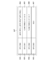
- FIG. 2 is a diagram for explaining an example of the configuration of the DICOM object acquired by the output control unit 104.
- FIG. 2A is an example of a configuration of an IOD including image data and metadata.
- the IOD 200 includes metadata 201 and image data 206.
- the metadata 201 includes patient information 202, examination information 203, series information 204, and image information 205.
- Patient information 202 is information on a patient (for example, a subject 1030) related to the IOD 200.
- the patient information 202 includes, for example, information on a patient ID for uniquely identifying a patient, patient name, date of birth, and sex.
- the inspection information 203 is inspection information related to the IOD 200.
- the inspection information 203 includes, for example, information on an inspection ID (Study Instance UID) for uniquely identifying an inspection, an inspection date, and an inspection time.
- an inspection ID (Study Instance UID) for uniquely identifying an inspection, an inspection date, and an inspection time.
- the series information 204 is information regarding the series included in the inspection indicated by the inspection information 203.
- the series information 204 includes, for example, a series ID (Series Instance UID) for uniquely identifying the series.
- the image information 205 is information about the image.
- the image information 205 includes the number of pixels, the number of bits, the patient orientation, and an image ID for uniquely identifying the image.
- the image ID is, for example, a SOP (Service Object Pair) Instance UID.
- the image information 205 may include information related to photoacoustic imaging such as the presence or absence of use of a contrast agent.
- the image data 206 is image pixel data. Image data 206 is generated by the image processing unit 103.
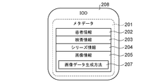
- FIG. 2B is an IOD consisting only of metadata.
- the IOD 208 does not include image data 206.
- the IOD 208 includes an image data generation method 207 that is information regarding a method for generating the image data 206.
- the image data generation method 207 includes information regarding a method for generating image data regarding the IOD 208.
- the method for generating image data includes, for example, information for identifying information necessary for generating the image data and a calculation method using the necessary information.
- the image data generation method 207 may be regarded as a method for enabling image data to be displayed on the Viewer 1024.
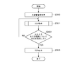
- FIG. 3 is a flowchart illustrating an example of a series of processes for acquiring an IOD that is an object for the information processing apparatus 100 to output to an external apparatus.
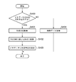
- FIG. 4 is a flowchart showing an example of details of the processing in step S301 shown in FIG. In the following processing, unless otherwise specified, the main body that realizes each processing is the CPU 1101 or the GPU. 5 and 6 are diagrams illustrating examples of information acquired by the information processing apparatus 100, respectively.
- step S300 the imaging control unit 102 acquires a photoacoustic signal from the imaging apparatus 1010.
- the photoacoustic signal measured using the light of two or more different wavelengths is acquired is demonstrated to an example.
- step S301 the output control unit 104 acquires an IOD related to a photoacoustic image generated based on the photoacoustic signal acquired in step S300.
- FIG. 4 is a flowchart showing an example of detailed processing in step S301.
- step S400 the determination unit 1042 determines a mode for outputting the DICOM object related to the photoacoustic signal acquired in step S401 to the external device based on the information stored in the setting unit 1041. If the determination unit 1042 determines to output an IOD including only metadata (for example, the IOD illustrated in FIG. 2B), the process proceeds to step S401, and an IOD including image data and metadata (for example, the IOD illustrated in FIG. 2A) is output. If so, the process proceeds to step S404.
- an IOD including only metadata for example, the IOD illustrated in FIG. 2B
- the determination unit 1042 acquires information on the type of photoacoustic image acquired by the inspection from the inspection control unit 101. For example, the determination unit 1042 acquires information indicating the type of photoacoustic image to be acquired included in the order acquired by the inspection control unit 101 as information regarding the type of photoacoustic image acquired by the inspection.
- the determination unit 1042 may acquire the content of an instruction input by the user via the user interface regarding the type of photoacoustic image to be acquired. For example, the determination unit 1042 acquires information on the type of photoacoustic image to be acquired at the time of inspection via a user interface in FIG.
- the determination unit 1042 may determine to acquire IODs relating to all acquirable photoacoustic images when the type of the photoacoustic image to be acquired is not specified by an order or input from the user. . Further, the determination unit 1042 may determine to acquire an IOD related to only a previously designated type (for example, an image related to a substance inside the subject such as oxygen saturation).
- the determination unit 1042 can generate an image showing the absorption coefficient distribution from an image showing the initial sound pressure distribution and an image showing the light amount distribution included in the order by referring to a table shown in FIG. 5 described later. It is determined that Then, for the image showing the absorption coefficient distribution, the determination unit 1042 determines that only the metadata of the photoacoustic image and metadata is output to the external device.
- the determination unit 1042 can generate a predetermined photoacoustic image included in a plurality of types of photoacoustic images to be acquired from a plurality of other photoacoustic images included in the plurality of types of photoacoustic images to be acquired. For the predetermined photoacoustic image, it is determined that only the metadata of the photoacoustic image and metadata is output to the external device. Note that the determination unit 1042 does not include, for example, an image showing the initial sound pressure distribution and an image showing the light amount distribution in the table shown in FIG. It is determined that it cannot be generated from the photoacoustic image included in the order. That is, for the image indicating the initial sound pressure distribution and the image indicating the light amount distribution, the determination unit 1042 determines to output the IOD including the photoacoustic image and metadata to the external device.
- the determination unit 1042 determines not to output image data for a plurality of types of photoacoustic images output to an external device and types that can be generated using other output photoacoustic images. By outputting only image data that is not generated using other photoacoustic images to an external device, the capacity for communication and storage can be reduced. From a certain point of view, the determination unit 1042 performs determination regarding the form of the IOD so that the number of image data to be output to the external device is reduced.
- the determination unit 1042 may determine that an IOD including a photoacoustic image and metadata is output to an external device for the type of photoacoustic image included in the order. In this case, for a photoacoustic image of a type not included in the order, the determination unit 1042 may determine to output an IOD that includes only metadata among image data and metadata. As a result, for example, when a user tries to acquire an IOD for a certain inspection using the Viewer 1024, an IOD including a photoacoustic image of the type requested in the inspection order can be acquired and can be displayed quickly.
- the viewer 1024 recognizes that the photoacoustic image of the type that is not requested in the inspection order can be acquired by the viewer 1024 due to the presence of the IOD, and the image data to be displayed is displayed. Can be presented to the user as a candidate.
- the determination unit 1042 determines image data, metadata, and the like for photoacoustic images other than the specified type. It may be determined that an IOD including only metadata is output.
- the determination unit 1042 acquires information stored in the setting unit 1041 for each type of photoacoustic image output to the external device.
- the setting unit 1041 stores information related to a type of photoacoustic image necessary to generate a certain type of photoacoustic image. Also, information input via a user interface in FIG. 9 described later is acquired.
- the determination unit 1042 acquires information indicating whether a certain type of photoacoustic image is output to the external apparatus as an IOD including only metadata or output to the external apparatus as an IOD including metadata and image data.
- the determination unit 1042 performs determination based on the setting information, and determines that it is output to an external device as an IOD including only metadata when it can be generated based on another type of photoacoustic image.
- the determination unit 1042 determines whether or not to output a certain type of photoacoustic image to the external device. And when it determines with outputting a photoacoustic image, it controls by the following processes so that IOD containing the said photoacoustic image and the metadata regarding the said photoacoustic image may be output to an external device. When it is determined not to output the photoacoustic image, control is performed by the following processing so that an IOD including only metadata regarding the photoacoustic image is output to the external device.
- step S401 the information acquisition unit 1043 acquires information on a method for generating a photoacoustic image of a type that outputs an IOD with only metadata from the setting unit 1041.
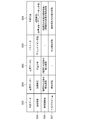
- FIG. 5 is an example of information regarding a method for generating each of a plurality of types of photoacoustic images (hereinafter referred to as a generation method).
- FIG. 5 is an example of information stored in the setting unit 1041.
- the generation method is stored in a table format, for example.
- Column 500 includes information on “generation data” that is the type of photoacoustic image to be generated.
- Column 501 and column 502 include information of “necessary data” that is a type of photoacoustic image necessary for generating each of the types of photoacoustic images shown in column 500.
- Column 503 includes parameter information necessary for generating each of the types of photoacoustic images shown in column 500.
- Column 504 includes “generation method” information for generating each of the types of photoacoustic images shown in column 500. “Generation method” indicates a method for generating the photoacoustic image of the column 500 using the information described in the columns 501 to 503.
- Line 505 indicates data, parameters, and generation methods necessary for generating an image related to the absorption coefficient, for example. Specifically, in order to generate an image related to the absorption coefficient, an image related to the initial sound pressure and an image related to the light amount distribution (light fluence distribution) are necessary, and it is shown that the Grueneisen coefficient is necessary as a parameter. It is shown that an image relating to the absorption coefficient is obtained by dividing the data of the initial sound pressure by the multiplication result of the light amount distribution data and the Gruneisen coefficient.
- Line 506 shows information necessary for generating an image related to oxygen saturation.
- a row 507 shows information necessary for generating an image related to the amount of hemoglobin.
- the mode for storing the generation method is not limited to the example shown in FIG.
- step S402 the information acquisition unit 1043 acquires information for describing the information related to the generation method acquired in step S401 in the metadata of the IOD. Specifically, the information acquisition unit 1043 converts information related to the generation method into a format conforming to the DICOM standard.
- FIG. 6 is a diagram illustrating an example when information on the generation method is converted into a format conforming to the DICOM standard.
- an image generation method related to an absorption coefficient (row 505 in FIG. 5) is indicated by a tag and its value will be described.
- the tag 600 is a private tag corresponding to an image generation method related to the absorption coefficient.
- a tag 601 and a tag 602 are private tags corresponding to necessary data for generating an image related to an absorption coefficient.
- a tag 603 is a private tag corresponding to a parameter for generating an image related to the absorption coefficient.
- the value 604 is the value of the tag 600, and indicates an operation performed using various data necessary for generating an image related to the absorption coefficient.
- the value 604 may be information for the external device to acquire the generation method, and may be information other than calculation.
- the value 604 may be information for identifying an operation for generating target image data, may be information on a storage destination path where information on a generation method is stored, or a link destination It may be the information.
- Value 605 and value 606 are the values of tag 601 and tag 602, respectively, and indicate information for uniquely identifying each necessary data.
- the value 605 and the value 606 are, for example, SOP instance UIDs of necessary data, and the apparatus that has acquired the IOD 208 can acquire necessary data from the information processing apparatus 100 and the PACS 1023 based on the SOP instance UID.
- the value 605 and the value 606 may be information for obtaining necessary data, and may be, for example, path information indicating a storage destination in the PACS 1023 or link destination information.
- the value 607 is the value of the tag 603 and indicates the parameter value.
- the aspect shown in FIG. 6 is merely an example, and it goes without saying that the present invention is not limited to this.
- step S403 the information acquisition unit 1043 adds information on the generation method converted into a format suitable for DICOM in step S402 as the image data generation method 207 of the metadata 201.
- step S404 the image processing unit 103 acquires a photoacoustic image based on the photoacoustic signal acquired in step S300.
- step S302 the output control unit 104 determines whether IODs relating to all types of photoacoustic images to be output to the external device have been acquired. If IODs related to all types of photoacoustic images have been acquired, the process proceeds to step S303. If there are types that have not yet been acquired, the process proceeds to step S302 to repeat the above-described processing.
- step S303 the communication unit 105 outputs the IOD acquired up to step S302 to an external device such as PACS1023 or Viewer1024.
- an external device such as PACS1023 or Viewer1024.
- the order of step S302 and step S303 is not limited to the above-described example, and for example, the communication unit 105 may sequentially output the acquired IOD to an external device.
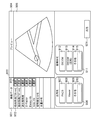
- FIG. 9 is an example of a screen 900 displayed on the display unit 1002 by the display control unit 106.
- the screen 900 is displayed on the display unit 1002 by the display control unit 106, for example, while performing the processing of FIG.
- the screen 900 allows the user to select the type of photoacoustic image to be output to the external device, to select the device that outputs the IOD, to select the format of the image data, and to specify the storage period of the image data. Provides a user interface.
- Column 901 displays the type of photoacoustic image.
- a button 903 for selecting whether or not to output the photoacoustic image of that type to the external device is displayed. The user can select the type of photoacoustic image to be output to the external device by operating the buttons. The button 903 is displayed in such a manner that the case where it is selected and the case where it is not selected can be distinguished.
- the output control unit 104 may acquire an IOD related to a photoacoustic image of a type selected by an operation input on the screen 900.
- the output of image data relating to the initial sound pressure distribution and the light amount distribution is set by default, and in such a case, a button for selecting to output the image data is displayed.
- a button for selecting to output the image data is displayed.
- the type selected by the button 903 is displayed.
- a photoacoustic image of the type selected by the button 903 is displayed as a preview.
- a preview is displayed after the image data is acquired in step S404 shown in FIG.
- the area 906 is an area for selecting a target to output an IOD related to a photoacoustic image of a type selected by an operation input to the button 903.
- a button 907 is a button for selecting output to the PACS 1023.
- a button 908 is a button for selecting output to the Viewer 1024.
- a button 909 is a button for the user to arbitrarily select an output destination, and an output destination can be designated by an operation input to the area 910.
- the communication unit 105 may output the IOD to the external device selected by the operation input on the area 904.
- the area 911 is an area for designating the format of the image data of the type of photoacoustic image selected by the operation input to the button 903.
- a button 912 is a button for designating a format of uncompressed image data in accordance with the DICOM standard.
- a button 913 is a button for designating a format (for example, JPEG2000) of image data compressed in accordance with the DICOM standard.
- a button 914 is a button for the user to arbitrarily select a format, and the format can be designated by an operation input to the area 915.
- the button 921 is a button for instructing the output of the IOD related to the photoacoustic image of the type selected by the operation input to the button 903.
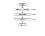
- FIG. 7 is a flowchart showing an example of processing for displaying a photoacoustic image on the Viewer 1024 based on the IOD acquired in the examples shown in FIGS. 3 to 6.
- the main body that realizes each processing is the CPU 1101 or the GPU.
- the Viewer 1024 is, for example, a computer, and the hardware configuration of the Viewer 1024 is the same as that in FIG.
- step S700 the viewer 1024 acquires an IOD from the PACS 1023 or the information processing apparatus 100. That is, the Viewer 1024 receives an object related to the photoacoustic image.
- step S701 the viewer 1024 determines whether image data is included in the IOD acquired in step S700. If the IOD includes only metadata and does not include image data, the process proceeds to step S702. If the IOD includes image data, the process proceeds to step S704.
- step S ⁇ b> 702 the viewer 1024 acquires information on the image data generation method 207 included in the metadata 201 of the IOD.
- the Viewer 1024 acquires the image data indicated by the IOD based on the information of the generation method 207.
- the viewer 1024 acquires the IOD from the PACS 1023 or the information processing apparatus 100. If the acquired IOD is a metadata-only IOD that does not include image data, the Viewer 1024 acquires information on the generation method 207 in the same manner as in step S702 described above, and image data based on the generation method. Just get it. That is, the Viewer 1024 acquires a photoacoustic image based on the acquired object metadata.
- step S704 the Viewer 1024 determines whether or not image data of all IODs to be displayed has been acquired. When the image data of all the IODs to be displayed are acquired, the processing shown in FIG. If there is an IOD to be displayed for which image data has not yet been acquired, the process proceeds to step S701 and the above-described processing is repeated.
- the Viewer 1024 can display the acquired image data on the IOD on a display unit (not shown).
- the Viewer 1024 displays a photoacoustic image based on the acquired IOD metadata, in particular, a DICOM tag related to a generation method.
- the user may install the processing program illustrated in FIG. 7.
- the processing 7 may be performed when an IOD is acquired by the Viewer 1024.
- the processing may be performed when the user performs an operation input for viewing image data of a specific IOD via the Viewer 1024.
- the user may set the Viewer 1024 so that the process is performed at a predetermined timing.
- the information processing apparatus 100 outputs image data necessary for displaying an image on the external apparatus to the external apparatus, does not generate unnecessary image data, and generates a method for generating the image data. Output metadata including the indicated information. Thereby, the capacity of data output from the information processing apparatus 100 can be reduced, and the capacity for communication and the capacity for storage of various devices can be reduced.
- the setting unit 1041 may further store information on the types that the user wants to preferentially observe on an external device such as the Viewer 1024. For example, for a photoacoustic image of a type that the user wants to preferentially observe information on the concentration distribution of a substance such as oxygen saturation, an IOD including metadata and a photoacoustic image is set to be output to an external device. Also good.
- the information processing apparatus 100 outputs an IOD including image data and metadata related to the distribution of the substance inside the subject to be used for diagnosis to the PACS 1023. Otherwise, only the metadata of the image data and metadata is output. Is output to the PACS1023.
- the information acquisition unit 1043 acquires an IOD including image data and metadata related to the distribution of a substance inside a subject to be used for diagnosis among a plurality of different types of photoacoustic images, and other types of photoacoustics.
- the image obtains an IOD that includes only metadata.
- the determination unit 1042 may perform the determination in step S400 without using the setting information. For example, the determination unit 1042 performs the determination in step S400 so that the number of image data to be output to the external device is the smallest among the types of photoacoustic images that are required to be output to the external device in an inspection order or the like. You may go.
- the output control unit 104 may warn the user when the combination of photoacoustic image types designated by the user as an object to be output to the external device is inappropriate. For example, the output control unit 104 warns the user when all kinds of image data cannot be displayed on the external apparatus unless they are output, that is, in a combination that cannot be generated by the external apparatus using other output image data. Do.
- the output control unit 104 may display a message to the user on the display unit 1002 via the display control unit 106 as the warning.
- the output control unit 104 may present the user with a combination of types that can output image data more efficiently than the combination designated by the user.
- the image processing unit 103 acquires the photoacoustic image when it is determined that not only the metadata but also the photoacoustic image is output to the external device among the photoacoustic image and the metadata.
- the present invention is not limited to this, and the image processing unit 103 may acquire a photoacoustic image regardless of the result of the determination in step S400. That is, the process of step S404 may be performed at any time before the IOD is output to the external device.
- step S400 if it is determined in step S400 that only the metadata among the photoacoustic image and metadata is output to the external device, the output control unit 104 does not acquire the photoacoustic image even if the image processing unit 103 acquires the photoacoustic image. Do not output photoacoustic image to external device.
- the image processing unit 103 acquires the intensity distribution of light irradiated on the subject in advance and acquires the light fluence distribution based on the light diffusion equation or the like has been described as an example, the present invention is not limited thereto.
- the image processing unit 103 may acquire the light fluence distribution on the assumption that the subject is irradiated with light uniformly.
- the image processing unit 103 may acquire the light fluence distribution by further considering the attenuation in the depth direction of the subject.
- an IOD including only metadata or an IOD including metadata and image data is acquired from the information processing apparatus 100, and the image data that the user desires to display is acquired in the stored PACS1023.
- An example of transmission will be described.
- the PACS 1023 has the same functional configuration as that of the image processing unit 103 of the information processing apparatus 100 illustrated in FIG.
- FIG. 8 is a flowchart showing an example of processing performed by the PACS1023.
- the main body that implements each processing is a processor (not shown) of PACS1023.
- step S800 the PACS 1023 accepts an image data transmission request from an external device such as a viewer 1024.
- step S801 the PACS 1023 acquires image data based on the transmission request acquired in step S801.
- the PACS 1023 searches for an IOD related to the type of photoacoustic image for which a transmission request has been made.
- the information processing apparatus 100 may be requested to output.
- the PACS 1023 acquires image data based on the image data generation method 207 included in the metadata 201 when the searched IOD does not include image data.
- the processing for acquiring image data based on the generation method 207 is the same as that described in the first embodiment. Detailed description is omitted here by using the above description.
- step S802 the PACS 1023 outputs an IOD including image data corresponding to the transmission request received in step S801 to the Viewer 1024.
- the PACS 1023 can suppress the capacity required for storing data received from the information processing apparatus 100.
- the image data can be easily displayed on the Viewer 1024 by acquiring the image data and outputting it to the Viewer 1024.
- the PACS 1023 may determine whether to output an IOD including only metadata or an IOD including image data and metadata depending on the function of the Viewer 1024. For example, if the Viewer 1024 has an image processing function, the image data may not be acquired in Step S901, and an IOD including only metadata may be output to the Viewer 1024 in Step S902.
- the information processing apparatus 100 may output an IOD related to a photoacoustic image by the following steps, and the PACS 1023 may acquire the IOD.
- the information processing apparatus 100 forms a second photoacoustic image (for example, an absorption coefficient distribution) using the first photoacoustic image data and other information (for example, information about the light fluence distribution).
- second photoacoustic image data for example, volume data.
- the information processing apparatus 100 transmits the first IOD including the first photoacoustic image data and the first metadata related to the first photoacoustic image to the PACS 1023. That is, the step in which the PACS 1023 obtains the first IOD.
- the PACS 1023 can generate the second photoacoustic image data based on the first photoacoustic image data.
- the information processing apparatus 100 transmits the second metadata including the information to the PACS1023.
- the information referred to here is, for example, information related to the light fluence distribution, or information related to a calculation formula for estimating the light intensity in the subject from the light intensity irradiated from the light source to the subject and the light intensity distribution.
- an ultrasonic image and a photoacoustic image acquired by an imaging apparatus that can acquire a photoacoustic signal and an ultrasonic signal may be the targets of the above-described processing.
- a CT image acquired by a CT (Computed Tomography) apparatus or an MRI image acquired by an MRI (Magnetic Resonance Imaging) apparatus may be the target of the above processing.
- a medical image acquired by any imaging device includes a plurality of types of image data generated based on a certain group of signals, and image data that can be generated based on a certain image data is included in the IOD.
- image data that can be generated based on a certain image data is included in the IOD.
- the IOD metadata that does not include image data may include all information other than image data, or may include only information to which an essential tag is added.
- the IOD metadata that does not include image data only needs to include information indicating a method for generating the image data.
- the example in which the IOD including the image data of the photoacoustic image and the IOD not including the image data of the photoacoustic image is output to the external device according to the type of the photoacoustic image has been described. Is not limited to this.
- the output control unit 104 according to the type of photoacoustic image, IOD including high-definition image data of the photoacoustic image, simple image data of the photoacoustic image, and high-definition image data from the simple image data.
- An IOD including information on a method for obtaining the information may be output to an external device.
- the external device that has acquired the IOD can read the metadata and acquire high-definition image data from simple image data based on other image data and numerical information. By controlling not to output high-definition image data for at least some types of photoacoustic images, the capacity for communication and storage can be reduced.
- the output control unit 104 may output an IOD including image data and metadata of a specific region (ROI) in the photoacoustic image to an external device. In that case, the output control unit 104 describes information for generating a region other than the ROI in the photoacoustic image in the metadata.
- the Viewer 1024 can acquire an IOD including ROI image data, and can easily display the display unit (not shown) of the Viewer 1024 on the ROI. Also, the Viewer 1024 can acquire an image of an area other than the ROI by reading the metadata.
- the present invention supplies a program that realizes one or more functions of the above-described embodiments to a system or apparatus via a network or a storage medium, and one or more processors in the computer of the system or apparatus read and execute the program This process can be realized. It can also be realized by a circuit (for example, ASIC) that realizes one or more functions.
- ASIC application specific integrated circuit
- the information processing apparatus in each of the above-described embodiments may be realized as a single apparatus, or may be configured to execute the above-described processing by combining a plurality of apparatuses so that they can communicate with each other. include.
- the above-described processing may be executed by a common server device or server group.
- the information processing apparatus and the plurality of apparatuses constituting the information processing system need only be able to communicate at a predetermined communication rate, and do not need to exist in the same facility or in the same country.
- a part of the functional configuration illustrated in FIG. 1 may be included in the PACS 1023 instead of the information processing apparatus 100, or may be included in the Viewer 1024, and the above-described processing is realized as a system including these apparatuses. May be.
- the image processing unit 103 and the output control unit 104 may be included in the PACS 1023, and the form of the IOD output by the PACS 1023 to the Viewer 1024 may be controlled.
- a software program that realizes the functions of the above-described embodiments is supplied to a system or apparatus, and the computer of the system or apparatus reads and executes the code of the supplied program. Includes form.
- the processing according to the embodiment is realized by a computer
- the program code itself installed in the computer is also one embodiment of the present invention.
- an OS or the like running on the computer performs part or all of the actual processing, and the functions of the above-described embodiments can be realized by the processing. .
- Embodiments appropriately combining the above-described embodiments are also included in the embodiments of the present invention.
Landscapes
- Health & Medical Sciences (AREA)
- Engineering & Computer Science (AREA)
- Life Sciences & Earth Sciences (AREA)
- Physics & Mathematics (AREA)
- Public Health (AREA)
- Medical Informatics (AREA)
- General Health & Medical Sciences (AREA)
- Radiology & Medical Imaging (AREA)
- Nuclear Medicine, Radiotherapy & Molecular Imaging (AREA)
- Theoretical Computer Science (AREA)
- Heart & Thoracic Surgery (AREA)
- Surgery (AREA)
- Veterinary Medicine (AREA)
- Animal Behavior & Ethology (AREA)
- Molecular Biology (AREA)
- Biomedical Technology (AREA)
- Pathology (AREA)
- Biophysics (AREA)
- Library & Information Science (AREA)
- Primary Health Care (AREA)
- Epidemiology (AREA)
- Data Mining & Analysis (AREA)
- Databases & Information Systems (AREA)
- General Engineering & Computer Science (AREA)
- General Physics & Mathematics (AREA)
- Acoustics & Sound (AREA)
- Physiology (AREA)
- Computer Networks & Wireless Communication (AREA)
- Ultra Sonic Daignosis Equipment (AREA)
Abstract
情報処理装置は、光音響信号に基づいて生成される複数の種類の光音響画像の種類に関する情報に基づいて、光音響画像を外部装置に出力するか否かを判定し、画像を外部装置に出力すると判定された場合には、光音響画像と光音響画像に関するメタデータとを外部装置に出力し、画像を外部装置に出力しないと判定された場合には、光音響画像とメタデータのうちメタデータのみを前記外部装置に出力する。
Description
本発明は、情報処理装置、情報処理方法、情報処理システム及びプログラムに関する。
被検体内部の状態を低侵襲に画像化する手法として、光音響イメージングの研究が進められている。光音響イメージングは、光に比べて生体内での散乱が少ない超音波の特性を利用して、生体内の光学特性値分布を高解像度に求める手法である。非特許文献1には、被検体内部で発生した超音波の信号に基づいて画像再構成を行い、被検体内部における音圧の分布を得ることが開示されている。さらに、音圧の分布に基づいて被検体内部における物質の吸収係数を画像化し、被検体内部における物質の成分比率や代謝といった機能に関する情報を表す様々な種類の画像が得られることが知られている。
M,Xu,L.V.Wang"Photoacoustic imaging in biomedicine",Review of scientific instruments,77,041101(2006)
光音響イメージングを利用した撮像装置を用いて、被検体内部で発生した超音波のある信号から、様々な種類の画像を取得することができる。しかしながら、一回の検査で得られた様々な種類の画像を全て保存したり、外部の装置に出力したりする場合には、保存や通信のための容量を圧迫するおそれがある。
本発明の実施形態に係る情報処理装置は、被検体に光を照射することにより得られる光音響信号に基づいて生成される複数の種類の光音響画像の種類に関する情報に基づいて、前記光音響画像を外部装置に出力するか否かを判定する判定手段と、前記判定手段により前記光音響画像を前記外部装置に出力すると判定された場合には、前記光音響画像と前記光音響画像に関するメタデータとを前記外部装置に出力し、前記判定手段により前記光音響画像を前記外部装置に出力しないと判定された場合には、前記光音響画像と前記メタデータのうち前記メタデータのみを前記外部装置に出力する出力手段と、を有することを特徴とする。
本発明によれば、光音響画像の種類に応じたメタデータを利用することで、光音響画像の外部装置への出力を省略できる場合がある。その場合には、保存や通信における負荷を低減することができる。
以下、図面を参照して本発明の実施形態を説明する。
[第1の実施形態]
本願明細書では、被検体に光を照射し、被検体内部で生じた膨張によって発生する音響波を光音響波と称する。
本願明細書では、被検体に光を照射し、被検体内部で生じた膨張によって発生する音響波を光音響波と称する。
被検体内部の状態を低侵襲に画像化する方法として、光音響イメージングが着目されている。光音響イメージングでは、光源から発生したパルス光を生体に照射し、生体内で伝播・拡散したパルス光のエネルギーを吸収した生体組織から発生した光音響波を検出する。光音響波を用いて画像化された画像を以下では光音響画像と称する。光音響イメージングでは、腫瘍などの被検部位とそれ以外の組織との光エネルギーの吸収率の差を利用し、被検部位が照射された光エネルギーを吸収して瞬間的に膨張する際に発生する弾性波(光音響波)をトランスデューサで受信する。この検出信号を以下では光音響信号と称する。光音響撮像装置は、光音響信号を解析処理することにより、生体内の光学特性分布、特に、光エネルギー吸収密度分布を得ることができる。光音響画像には、被検体内部の光学特性に応じた、様々な種類の画像がある。たとえば、光音響画像には吸収密度分布を示す吸収係数画像が含まれる。また、吸収係数画像から、酸化ヘモグロビン、還元ヘモグロビン、水、脂肪、コラーゲンといった生体分子の存在や、比率等を示す画像が生成される。たとえば、酸化ヘモグロビンと還元ヘモグロビンとの比率に基づいて、ヘモグロビンの酸素との結合状況を示す指標である酸素飽和度に関する画像が得られる。
また近年では、上述の光音響画像を含め、診断に用いられる医用画像や診断に関する各種の情報が電子化されている。撮像装置と、当該撮像装置と接続される各種の装置との間の情報連携のために、たとえばDICOM(Digital Imaging and Communications in Medicine)規格が用いられることが多い。DICOMは医用画像のフォーマットと、それらの画像を扱う装置間の通信プロトコルを定義した規格である。DICOMに基づいてやりとりされる対象となるデータは情報オブジェクト(IOD:Information Object Definitions)と呼ばれる。以下では、情報オブジェクトをIOD、或いはオブジェクトと称する場合がある。IODの例としては、医用画像、患者情報、検査情報、構造化レポート等が挙げられ、医用画像を用いた検査や治療にかかわる様々なデータがその対象となり得る。
DICOMに基づいて取り扱われる画像、すなわちIODである画像は、メタデータと画像データとで構成される。メタデータには、たとえば患者、検査、シリーズ、画像に関する情報が含まれる。メタデータはDICOMデータエレメントと呼ばれるデータ要素の集まりで構成される。各々のDICOMデータエレメントにはデータ要素を識別するためのタグが付加される。DICOMデータエレメントの一例である、ピクセルデータ(画像データ)には、画像データであることを示すタグが付加される。メタデータのそれぞれにおいても、たとえば患者氏名には、患者氏名であることを示すタグが付加される。当該メタデータと当該画像データをDICOMデータセットとする場合、IODは当該DICOMデータセットに対するDICOMファイルメタ情報をさらに含んでもよい。DICOMファイルメタ情報は、たとえばIOD(DICOMファイル)を作成したアプリケーションの情報を含む。
光音響画像を医療施設内における様々な装置で利用するために、光音響画像もDICOM規格に則ってIODとして光音響撮像装置から出力されることが好ましい。光音響イメージングでは、上述したように1回の撮影に係る光音響信号から様々な種類の光音響画像を取得できるが、取得された複数の光音響画像を全て保存したり、通信したりすると、保存や通信に係る容量を圧迫するおそれがある。第1の実施形態では、光音響画像に関するメタデータを利用して、保存や通信に係る容量を低減できるようにIODを出力することを目的とする。
[情報処理装置の構成]
図10は、第1の実施形態に係る情報処理装置100を含むシステム1000の構成の一例を示す図である。システム1000は、情報処理装置100と、光音響撮像装置1010とを含む。情報処理装置100には操作部1001と表示部1002とが接続されている。情報処理装置100はネットワーク1020に接続する。ネットワーク1020には、HIS1021、オーダリング装置1022、PACS1023、Viewer1024、Printer1025が接続されている。システム1000は、たとえば医療施設内の情報システムである。システム1000に含まれる各構成は、同じ施設内に設置されている必要はなく、通信可能に接続されていればよい。
図10は、第1の実施形態に係る情報処理装置100を含むシステム1000の構成の一例を示す図である。システム1000は、情報処理装置100と、光音響撮像装置1010とを含む。情報処理装置100には操作部1001と表示部1002とが接続されている。情報処理装置100はネットワーク1020に接続する。ネットワーク1020には、HIS1021、オーダリング装置1022、PACS1023、Viewer1024、Printer1025が接続されている。システム1000は、たとえば医療施設内の情報システムである。システム1000に含まれる各構成は、同じ施設内に設置されている必要はなく、通信可能に接続されていればよい。
情報処理装置100は、光音響画像の撮像を含む検査に関する情報をオーダリング装置1022から取得し、当該検査が行われる際に光音響撮像装置1010(以下では、撮像装置1010と称する。)を制御する。情報処理装置100は、撮像装置1010から光音響信号を取得する。情報処理装置100は、光音響信号に基づいて光音響画像を取得する。情報処理装置100は、HL7(Health level 7)及びDICOM(Digital Imaging and Communications in Medicine)といった規格に準じて、HIS1021、オーダリング装置1022、PACS1023といった外部装置との間で情報の送受信を行う。
操作部1001は、ユーザの操作入力に関する情報を情報処理装置100に送信する。操作部1001は、たとえばキーボードやトラックボールや、検査に関する操作入力を行うための各種のボタンである。
表示部1002は、情報処理装置100からの制御に基づいて、システム1000で撮像された画像や、検査に関する情報を表示する。表示部1002は、情報処理装置100からの制御に基づいて、ユーザの指示を受け付けるためのインタフェースを提供する。表示部1002は、たとえば液晶ディスプレイである。
なお、表示部1002と操作部1001はタッチパネルディスプレイとして統合されていてもよい。また、情報処理装置100と表示部1002と操作部1001は別体の装置である必要はなく、これらの構成が統合された操作卓として実現されてもよい。情報処理装置100は、複数のプローブを有していてもよい。
撮像装置1010は、光音響イメージングの手法により、光音響信号を取得する。対象とする被検体内の領域は、たとえば循環器領域、乳房、径部、腹部、手指および足指を含む四肢といった領域である。特に、被検体内の光吸収に関する特性に応じて、新生血管や血管壁のプラークを含む血管領域を、光音響画像の撮像の対象としてもよい。システム1000では、たとえばメチレンブルー(methylene blue)やインドシアニングリーン(indocyanine green)といった色素や、金微粒子、それらを集積あるいは化学的に修飾した物質を造影剤として投与した被検体1030の光音響画像を撮像してもよい。
撮像装置1010は、被検体1030に光を照射する照射部1012と、被検体1030からの光音響波を受信する受信部1011とを含む。
受信部1011は、少なくとも1つのトランスデューサ(不図示)と、整合層(不図示)、ダンパー(不図示)、音響レンズ(不図示)を含む。トランスデューサ(不図示)はPZT(lead zirconate titanate)やPVDF(polyvinylidene difluoride)といった、圧電効果を示す物質からなる。トランスデューサ(不図示)は圧電素子以外のものでもよく、たとえば静電容量型トランスデューサ(CMUT:capacitive micro-machined ultrasonic transducers)、ファブリペロー干渉計を用いたトランスデューサである。典型的には、光音響信号は0.1~100MHzの周波数成分からなり、トランスデューサ(不図示)は、たとえばこれらの周波数を検出できるものが用いられる。トランスデューサ(不図示)により得られる信号は時間分解信号である。受信された信号の振幅は各時刻にトランスデューサで受信される音圧に基づく値を表したものである。受信部1011は、電子フォーカスのための回路(不図示)もしくは制御部を含む。トランスデューサ(不図示)の配列形は、たとえばセクタ、リニアアレイ、コンベックス、アニュラアレイ、マトリクスアレイである。受信部1011は、トランスデューサ(不図示)が受信した時系列のアナログ信号を増幅する増幅器(不図示)を備えていてもよい。
照射部1012は、光音響信号を取得するための光源(不図示)と、光源(不図示)から射出されたパルス光を被検体へ導く光学系(不図示)とを含む。光源(不図示)が射出する光のパルス幅は、たとえば1ns以上、100ns以下のパルス幅である。また、光源(不図示)が射出する光の波長は、たとえば400nm以上、1600nm以下の波長である。被検体の表面近傍の血管を高解像度でイメージングする場合は、400nm以上、700nm以下の、血管での吸収が大きい波長が好ましい。また、被検体の深部をイメージングする場合には、700nm以上、1100nm以下の、水や脂肪といった組織で吸収されにくい波長が好ましい。
光源(不図示)は、たとえばレーザーや発光ダイオードである。照射部1012は、複数の波長の光を用いて光音響信号を取得するために、波長を変換できる光源を用いてもよい。あるいは、照射部1012は、互いに異なる波長の光を発生する複数の光源を備え、それぞれの光源から交互に異なる波長の光を照射できる構成であってもよい。レーザーは、たとえば固体レーザー、ガスレーザー、色素レーザー、半導体レーザーである。光源(不図示)として、Nd:YAGレーザーやアレキサンドライトレーザーといったパルスレーザーを用いてもよい。また、Nd:YAGレーザーの光を励起光とするTi:saレーザーやOPO(optical parametric oscillators)レーザーを光源(不図示)として用いてもよい。また、光源(不図示)として、マイクロウェーブ源を用いてもよい。
光学系(不図示)には、レンズ、ミラー、光ファイバといった光学素子が用いられる。被検体が乳房である場合には、パルス光のビーム径を広げて照射することが好ましいため、光学系(不図示)は射出される光を拡散させる拡散板を備えていてもよい。あるいは解像度を上げるために、光学系(不図示)はレンズ等を備え、ビームをフォーカスできる構成であってもよい。
撮像装置1010は、受信部1011が受信した光音響波のアナログ信号をデジタル信号である光音響信号に変換し、情報処理装置100に送信する。
HIS(Hospital Information System)1021は、病院の業務を支援するシステムである。HISは、電子カルテシステム、オーダリングシステムや医事会計システムを含む。HIS1021は、検査が完了したことを示す情報を情報処理装置100又はオーダリング装置1022から受信すると、会計のための処理を行う。
オーダリング装置1022は、検査情報を管理し、撮像装置のそれぞれの検査の進捗を管理するシステムである。放射線部門におけるオーダリング装置1022は、たとえばRIS(Radiology Information System)である。検査情報は、検査を一意に識別するための検査IDや、当該検査に含まれる撮影手技に関する情報を含む。オーダリング装置1022は、情報処理装置100からの問い合わせに応じて、撮像装置1010で行う検査の情報を情報処理装置100に送信する。オーダリング装置1022は、情報処理装置100から検査の進捗に関する情報を受信する。
HIS1021及びオーダリング装置1022により、検査のオーダ発行から会計までが連携して管理される。
PACS(Picture Archiving and Communication System)1023は、施設内外の各種の撮像装置で得られた画像を保持するデータベースシステムである。PACS1023はたとえばPACSサーバである。PACS1023は、医用画像及びかかる医用画像の撮影条件や、再構成を含む画像処理のパラメータや患者情報といった付帯情報を記憶する記憶部(不図示)と、当該記憶部に記憶される情報を管理するコントローラ(不図示)とを有する。PACS1023は、情報処理装置100から出力されたオブジェクトである、超音波画像や光音響画像や重畳画像を記憶する。PACS1023と情報処理装置100との通信や、PACS1023に記憶される各種の画像はHL7やDICOMといった規格に則していることが好ましい。情報処理装置100から出力される各種の画像は、DICOM規格に則って各種のタグに付帯情報が関連付けられ、記憶されている。
Viewer1024は、画像診断用の端末であり、PACS1023等に記憶された画像を読み出し、診断のために表示する。医師は、Viewer1024に画像を表示させて観察し、当該観察の結果得られた情報を画像診断レポートとして記録する。Viewer1024を用いて作成された画像診断レポートは、Viewer1024に記憶されていてもよいし、PACS1023やレポートサーバ(不図示)に出力され、記憶されてもよい。
Printer1025は、PACS1023等に記憶された画像を印刷する。Printer1025はたとえばフィルムプリンタであり、PACS1023等に記憶された画像をフィルムに印刷することにより出力する。
図11は、情報処理装置100のハードウェア構成の一例を示す図である。情報処理装置100は、たとえばコンピュータである。情報処理装置100は、CPU1101、ROM1102、RAM1103、記憶装置1104、USB1105、通信回路1106、グラフィックスボード1107を有する。これらはBUSにより通信可能に接続されている。BUSは接続されたハードウェア間でのデータの送受信や、CPU1101から他のハードウェアへの命令を送信するために使用される。
CPU(Central Processing Unit)1101は情報処理装置100及びこれに接続する各部を統合的に制御する制御回路である。CPU1101はROM1102に格納されているプログラムを実行することにより制御を実施する。またCPU1101は、表示部1002を制御するためのソフトウェアであるディスプレイドライバを実行し、表示部1002に対する表示制御を行う。さらにCPU1101は、操作部1001に対する入出力制御を行う。
ROM(Read Only Memory)1102は、CPU1101による制御の手順を記憶させたプログラムやデータを格納する。ROM1102は、情報処理装置100のブートプログラムや各種初期データを記憶する。また、情報処理装置100の処理を実現するための各種のプログラムを記憶する。
RAM(Random Access Memory)1103は、CPU1101が命令プログラムによる制御を行う際に作業用の記憶領域を提供するものである。RAM1103は、スタックとワーク領域とを有する。RAM1103は、情報処理装置100及びこれに接続する各部における処理を実行するためのプログラムや、画像処理で用いる各種パラメータを記憶する。RAM1103は、CPU1101が実行する制御プログラムを格納し、CPU1101が各種制御を実行する際の様々なデータを一時的に格納する。
記憶装置1104は、超音波画像や光音響画像などの各種のデータを保存する補助記憶装置である。記憶装置1104は、たとえばHDD(Hard Disk Drive)や、SSD(Solid State Drive)である。
USB(Universal Serial Bus)1105は操作部1001と接続する接続部である。
通信回路1106はシステム1000を構成する各部や、ネットワーク1020に接続されている各種の外部装置との通信を行うための回路である。通信回路1106は、たとえば出力する情報を転送用パケットに格納してTCP/IPといった通信技術により、ネットワーク1020を介して外部装置に出力する。情報処理装置100は、所望の通信形態にあわせて、複数の通信回路を有していてもよい。
グラフィックスボード1107は、GPU(Graphics ProcessingUnit)、ビデオメモリを含む。GPUは、たとえば光音響信号から光音響画像を生成するための再構成処理に係る演算を行う。
HDMI(登録商標)(High Definition Multimedia Interface)1108は、表示部1002と接続する接続部である。
CPU1101やGPUはプロセッサの一例である。また、ROM1102やRAM1103や記憶装置1104はメモリの一例である。情報処理装置100は複数のプロセッサを有していてもよい。第1の実施形態においては、情報処理装置100のプロセッサがメモリに格納されているプログラムを実行することにより、情報処理装置100の各部の機能が実現される。
また、情報処理装置100は特定の処理を専用に行うCPUやGPU、ASIC(Application Specific Integrated Circuit)を有していても良い。情報処理装置100は特定の処理あるいは全ての処理をプログラムしたFPGA(Field-Programmable Gate Array)を有していてもよい。
図1は、情報処理装置100の機能構成の一例を示す図である。情報処理装置100は、検査制御部101、撮影制御部102、画像処理部103、出力制御部104、通信部105、表示制御部106を有する。
検査制御部101は、検査制御部101は、オーダリング装置1022から検査オーダの情報を取得する。検査オーダには、検査を受ける患者の情報や、撮影手技に関する情報が含まれる。また、検査オーダには光音響信号により生成される複数種類の光音響画像のうち医師等のユーザが要求する光音響画像の種類を示す情報が含まれていてもよい。検査制御部101は、撮影制御部102に検査オーダに関する情報を送信する。また、検査制御部101は、表示制御部106を介してユーザに検査に関する情報を提示するために表示部1002に当該検査の情報を表示させる。表示部1002に表示される検査の情報には、検査を受ける患者の情報や、当該検査に含まれる撮影手技の情報や、既に撮像が完了して生成された画像が含まれる。さらに検査制御部101は、通信部105を介して当該検査の進捗に関する情報をオーダリング装置1022に送信する。
撮影制御部102は、検査制御部101から受信した撮影手技の情報に基づいて撮像装置1010を制御し、光音響信号を撮像装置1010から取得する。撮影制御部102は、照射部1012への指示と受信部1011への指示とをユーザの操作入力や撮影手技の情報に基づいて実行する。撮影制御部102は、照射部1012に対して光の照射を指示する。また、撮影制御部102は受信部1011に対して光音響波の受信を指示する。撮影制御部102は、撮像装置1010においてデジタル信号に変換された光音響信号を取得する。すなわち、撮影制御部102は、光音響信号を取得する信号取得手段の一例である。
画像処理部103は、光音響画像を生成する。また、画像処理部103は光音響画像からなる動画像を生成する。
具体的には、画像処理部103は撮影制御部102により取得された光音響信号に基づいて光音響画像を生成する。画像処理部103は、光音響信号に基づいて光が照射された時の音響波の分布(以下、初期音圧分布と称する。)を再構成する。画像処理部103は、予め被検体に照射される光の強度分布を取得して、たとえば以下に示す考え方により光フルエンスに関する情報を取得する。
画像処理部103は、光を吸収、散乱する媒質における光エネルギーの挙動を示す輸送方程式や拡散方程式を数値的に解く方法により、被検体の内部における光フルエンスの空間分布を算出することができる。数値的に解く方法としては、有限要素法、差分法、モンテカルロ法等を採用することができる。例えば、画像処理部103は、既知の光拡散方程式を解くことにより、被検体の内部における光フルエンスの空間分布(光フルエンス分布、光量分布)を算出してもよい。
画像処理部103は、再構成された初期音圧分布を、被検体に照射された光の被検体の光フルエンス分布(光量分布)で除することにより、被検体内における光の吸収係数分布を取得する。また、被検体に照射する光の波長に応じて、被検体内で光の吸収の度合いが異なることを利用して、複数の波長に対する吸収係数分布から被検体内の物質の濃度分布を取得する。たとえば画像処理部103は、オキシヘモグロビンとデオキシヘモグロビンの被検体内における物質の濃度分布を取得する。さらに画像処理部103は、オキシヘモグロビン濃度のデオキシヘモグロビン濃度に対する割合として酸素飽和度分布を取得する。画像処理部103により生成される光音響画像は、たとえば上述した初期音圧分布、光フルエンス分布、吸収係数分布、物質の濃度分布および酸素飽和度分布の少なくとも一つの情報を示す画像である。上述したように、吸収係数分布、物質の濃度分布及び酸素飽和度分布のそれぞれに関する画像は、初期音圧分布及び光フルエンス分布に関する画像に基づいて生成される。また、物質の濃度分布及び酸素飽和度分布のそれぞれに関する画像は、2波長分の吸収係数分布に関する画像に基づいて生成される。すなわち、画像処理部103は複数種類の光音響画像を取得する。画像処理部103は光音響画像を取得する画像取得手段の一例である。
出力制御部104は、画像に関するメタデータの生成に係る情報を取得し、外部装置に出力するためのオブジェクト(以下、DICOMオブジェクトと称する場合がある)を生成する。出力制御部104は、設定部1041、判定部1042、情報取得部1043を含む。
設定部1041は、DICOMオブジェクトとして出力すべき情報と、画像データの種別とに関する設定を、RAM1103といったメモリから読み出して取得する。画像処理部103の説明において述べたように、ある一群の光音響信号に基づいて生成される複数の種類の光音響画像のうち、いくつかの種類の光音響画像は他の光音響画像に基づいて生成される。たとえば、物質の濃度分布に関する画像は複数の波長の吸収係数分布に関する画像に基づいて生成される。設定部1041は、ある種類の光音響画像を生成するために必要な種類の光音響画像に関する情報を記憶する。当該設定は、検査に先だってユーザが入力しておいてもよい。
判定部1042は、光音響画像と光音響画像に関するメタデータのうち光音響画像に関するメタデータのみを外部装置に出力するか、光音響画像とメタデータとを外部装置に出力するか判定する。判定部1042は、例えば、検査制御部101、撮影制御部102の少なくともいずれかにおいて取得された情報と、設定部1041に記憶された情報とに基づいて、光音響画像に関するメタデータのみを外部装置に出力するか、光音響画像とメタデータとを外部装置に出力するか判定する。判定部1042は、設定部1041に記憶された光音響画像の生成に必要な種類の光音響画像に関する情報に基づいて、判定を行う。判定部1042は、外部装置において生成可能である種類の光音響画像についてはメタデータのみのIODを出力し、外部装置において生成不可能である種類の光音響画像についてはメタデータと当該光音響画像とを含むIODを出力するように判定する。すなわち判定部1042は外部装置に出力しようとする光音響画像の種類に関する情報に基づいて、当該光音響画像を外部装置に出力するか否かを判定する。光音響画像とメタデータとを外部装置に出力すると判定した場合には、判定部1042は画像処理部103を制御して当該光音響画像を生成させる。判定部1042は判定手段の一例である。
情報取得部1043は、外部装置に出力するためのDICOMオブジェクトを取得する。また、情報取得部1043はDICOMオブジェクトを生成するために必要な情報を取得する。たとえば情報取得部1043は検査制御部101、撮影制御部102や撮像装置1010から、患者情報や検査情報といった光音響画像の取得に関する情報を取得する。情報取得部1043は、当該DICOMオブジェクトに含まれるメタデータの情報を取得する。情報取得部1043は、メタデータに記載すべき情報を、DICOM規格に則った形式に変換することにより、メタデータの情報を取得してもよい。情報取得部1043は、当該メタデータの情報をDICOMエレメントとして取得する。DICOMエレメントは、DICOMタグ(gggg,eeee)の形式で表される識別子と、データの内容を表す情報とで構成される。また、情報取得部1043は画像処理部103において生成された光音響画像の画像データを取得する。情報取得部1043は、情報取得手段の一例である。
通信部105は、ネットワーク1020を介してHIS1021、オーダリング装置1022、PACS1023、Viewer1024といった外部装置と情報処理装置100との間での、情報の送受信を制御する。
表示制御部106は、表示部1002を制御して、表示部1002に情報を表示させる。表示制御部106は、他のモジュールからの入力や、操作部1001を介したユーザの操作入力に応じて、表示部1002に情報を表示させる。表示制御部106は、表示制御手段の一例である。
図2は、出力制御部104により取得されるDICOMオブジェクトの構成の一例を説明するための図である。図2Aは、画像データとメタデータとを含むIODの構成の一例である。IOD200はメタデータ201と画像データ206とを含む。メタデータ201は、患者情報202と検査情報203とシリーズ情報204と画像情報205とを含む。
患者情報202は、IOD200に関する患者(たとえば被検体1030)の情報である。患者情報202には、たとえば患者を一意に識別するための患者IDや、患者名、生年月日、性別に関する情報が含まれる。
検査情報203は、IOD200に関する検査の情報である。検査情報203には、たとえば検査を一意に識別するための検査ID(Study Instance UID)や、検査日、検査時間に関する情報が含まれる。
シリーズ情報204は、検査情報203により示される検査に含まれるシリーズに関する情報である。シリーズ情報204は、たとえばシリーズを一意に識別するためのシリーズID(Series Instance UID)が含まれる。
画像情報205は、画像に関する情報である。画像情報205は、画素数、ビット数、患者の向き、画像を一意に識別するための画像IDが含まれる。画像IDは、たとえばSOP(Service Object Pair) Instance UIDである。また、画像情報205はたとえば造影剤の使用の有無など、光音響撮像に関する情報を含んでいてもよい。
画像データ206は、画像のピクセルデータである。画像データ206は画像処理部103で生成される。
図2BはメタデータのみからなるIODである。IOD208は画像データ206を含まない。IOD208は、画像データ206を生成するための方法に関する情報である、画像データ生成方法207を含む。画像データ生成方法207は、IOD208に関する画像データを生成するための方法に関する情報を含む。画像データを生成するための方法には、たとえば当該画像データを生成するために必要な情報を識別するための情報と、必要な情報を用いた演算の方法とを含む。別の観点では、画像データ生成方法207は、Viewer1024で画像データを表示可能にするための方法ととらえてもよい。
[情報処理装置により行われる一連の処理]
図3は、情報処理装置100が外部装置に出力するためのオブジェクトであるIODを取得する一連の処理の一例を示すフローチャートである。図4は、図3に示すステップS301の処理の詳細の一例を示すフローチャートである。下記の処理において、特に断りがない場合、各処理を実現する主体は、CPU1101またはGPUである。また、図5及び図6はそれぞれ、情報処理装置100により取得される情報の一例を示す図である。
図3は、情報処理装置100が外部装置に出力するためのオブジェクトであるIODを取得する一連の処理の一例を示すフローチャートである。図4は、図3に示すステップS301の処理の詳細の一例を示すフローチャートである。下記の処理において、特に断りがない場合、各処理を実現する主体は、CPU1101またはGPUである。また、図5及び図6はそれぞれ、情報処理装置100により取得される情報の一例を示す図である。
ステップS300において、撮影制御部102は光音響信号を撮像装置1010から取得する。以下では、2つ以上の異なる波長の光を用いて計測した光音響信号を取得する場合を例に説明する。
ステップS301において、出力制御部104は、ステップS300で取得された光音響信号に基づいて生成される光音響画像に関するIODを取得する。
図4は、ステップS301の詳細な処理の一例を示すフローチャートである。
ステップS400において、判定部1042は、設定部1041に記憶された情報に基づいてステップS401で取得された光音響信号に関するDICOMオブジェクトを外部装置に出力する形態について判定する。判定部1042がメタデータのみを含むIOD(たとえば図2Bに示すIOD)を出力すると判定した場合にはステップS401に進み、画像データとメタデータとを含むIOD(たとえば図2Aに示すIOD)を出力すると判定した場合にはステップS404に進む。
具体的には、判定部1042は検査制御部101から検査で取得する光音響画像の種類に関する情報を取得する。例えば、判定部1042は、検査制御部101が取得したオーダに含まれる取得すべき光音響画像の種類を示す情報を検査で取得する光音響画像の種類に関する情報として取得する。また、判定部1042は検査に際して、取得する光音響画像の種類に関してユーザインタフェースを介してユーザが入力した指示の内容を取得することとしてもよい。判定部1042は、例えば、後述する図9のユーザインタフェースを介して検査に際して取得すべき光音響画像の種類に関する情報を取得する。なお、判定部1042はオーダまたはユーザからの入力によって取得すべき光音響画像の種類が特に指定されていない場合は、取得可能な全ての光音響画像に関するIODを取得するように判定してもよい。また、判定部1042は、予め指定された種類(たとえば、酸素飽和度といった、被検体の内部の物質に関する画像)のみに関するIODを取得するように判定してもよい。
例えば、オーダに初期音圧分布を示す画像、光量分布を示す画像および吸収係数分布を示す画像が取得すべき光音響画像である旨の情報が含まれている場合を考える。この場合、判定部1042は、後述する図5に示すテーブルを参照することで、吸収係数分布を示す画像はオーダに含まれている初期音圧分布を示す画像および光量分布を示す画像から生成可能であると判定する。そして、判定部1042は、吸収係数分布を示す画像に関しては、光音響画像およびメタデータのうちメタデータのみIODを外部装置に出力すると判定する。すなわち、判定部1042は取得すべき複数種類の光音響画像に含まれる所定の光音響画像に関して、取得すべき複数種類の光音響画像に含まれる他の複数の光音響画像により生成可能である場合には、所定の光音響画像に関して光音響画像およびメタデータのうちメタデータのみIODを外部装置に出力すると判定する。なお、判定部1042は、例えば図5に示すテーブルに、初期音圧分布を示す画像および光量分布を示す画像が記載されていないことから、初期音圧分布を示す画像および光量分布を示す画像はオーダに含まれる光音響画像から生成することができないと判定する。すなわち、判定部1042は、初期音圧分布を示す画像および光量分布を示す画像に関しては、光音響画像およびメタデータを含むIODを外部装置に出力すると判定する。
すなわち、判定部1042は外部装置に出力する複数の種類の光音響画像のうち、出力される他の光音響画像を用いて生成可能な種類については画像データを出力しないように判定する。他の光音響画像を用いて生成されない画像データのみを外部装置に出力するようにすることで、通信や保存にかかる容量を低減することができる。ある観点では、判定部1042は外部装置に出力する画像データの数が少なくなるように、IODの形態に関する判定を行う。
また、判定部1042は、オーダに含まれている種類の光音響画像に関しては、光音響画像およびメタデータを含むIODを外部装置に出力すると判定することとしてもよい。この場合、オーダに含まれない種類の光音響画像に関しては、判定部1042は画像データとメタデータとのうちメタデータのみを含むIODを出力すると判定してもよい。これにより、たとえばユーザがViewer1024を用いてある検査のIODを取得しようとした場合に、検査オーダで要求した種類の光音響画像を含むIODを取得でき、速やかにそれを表示できる。さらに、Viewer1024は検査オーダで要求しなかった種類の光音響画像についても、IODが存在することにより、Viewer1024はそれらの種類の光音響画像を取得可能であることを認識し、表示させる画像データの候補としてユーザに提示することができる。
さらに、後述する図9のユーザインタフェースを介して取得すべき光音響画像の種類が指定された場合でも同様に、判定部1042は指定された種類以外の光音響画像に関して、画像データとメタデータとのうちメタデータのみを含むIODを出力することと判定してもよい。
外部装置に出力する光音響画像の種類のそれぞれについて、判定部1042は設定部1041に記憶された情報を取得する。設定部1041は、ある種類の光音響画像を生成するのに必要な種類の光音響画像に関する情報が記憶される。また、後述する図9のユーザインタフェースを介して入力された情報を取得する。判定部1042はある光音響画像の種類について、メタデータのみを含むIODとして外部装置に出力するか、メタデータと画像データとを含むIODとして外部装置に出力するかを示す情報を取得する。判定部1042は、当該設定の情報に基づいて判定を行い、他の種類の光音響画像に基づいて生成可能である場合には、メタデータのみを含むIODとして外部装置に出力すると判定する。すなわち判定部1042は、ある種類の光音響画像を外部装置に出力するか否かを判定する。そして、光音響画像を出力すると判定された場合には、当該光音響画像と当該光音響画像に関するメタデータとを含むIODを外部装置に出力するように以下の処理で制御される。光音響画像を出力しないと判定された場合には、当該光音響画像に関するメタデータのみを含むIODを外部装置に出力するように以下の処理で制御される。
ステップS401において、情報取得部1043はメタデータのみのIODを出力する種類の光音響画像を生成するための方法に関する情報を設定部1041から取得する。
図5は、複数の種類の光音響画像のそれぞれを生成するための方法(以下では、生成方法と称する。)に関する情報の一例である。図5は設定部1041に記憶される情報の一例である。生成方法は、たとえばテーブル形式で記憶される。
列500は、生成する対象となる光音響画像の種類である「生成データ」の情報を含む。
列501及び列502は、列500に示される光音響画像の種類のそれぞれを生成するのに必要な光音響画像の種類である「必要データ」の情報を含む。
列503は、列500に示される光音響画像の種類のそれぞれを生成するのに必要なパラメータの情報を含む。
列504は、列500に示される光音響画像の種類のそれぞれを生成するための「生成方法」の情報を含む。「生成方法」は列501から列503に記載された情報を用いて列500の光音響画像を生成するための方法を示す。
行505は、たとえば吸収係数に関する画像を生成するために必要なデータ、パラメータ及び生成方法を示す。具体的には、吸収係数に関する画像を生成するためには初期音圧に関する画像と光量分布(光フルエンス分布)に関する画像が必要であり、パラメータとしてグリュナイゼン係数が必要であることが示されている。そして、吸収係数に関する画像は、初期音圧のデータを、光量分布のデータとグリュナイゼン係数の乗算結果で除することにより得られることが示されている。
行506は、酸素飽和度に関する画像を生成するために必要な情報を示す。行507は、ヘモグロビン量に関する画像を生成するために必要な情報を示す。なお、生成方法を記憶するための態様は図5に示した例に限られない。
ステップS402において、情報取得部1043はステップS401で取得した生成方法に関する情報を、IODのメタデータに記載するための情報を取得する。具体的には、情報取得部1043は当該生成方法に関する情報をDICOM規格に則った形式に変換する。
図6は、生成方法に関する情報をDICOM規格に則った形式に変換した場合の一例を示す図である。ここでは、吸収係数に関する画像の生成方法(図5の行505)をタグとその値で示す例を説明する。
タグ600は、吸収係数に関する画像の生成方法に対応するプライベートタグである。タグ601及びタグ602は、吸収係数に関する画像を生成するための必要データに対応するプライベートタグである。タグ603は、吸収係数に関する画像を生成するためのパラメータに対応するプライベートタグである。
値604はタグ600の値であり、吸収係数に関する画像を生成するために必要な各種のデータを用いて行う演算を示す。値604は、生成方法を外部装置が取得するための情報であればよく、演算以外の情報でもよい。たとえば、値604は対象とする画像データを生成するための演算を識別するための情報でもよいし、生成方法に関する情報が保存されている保存先のパスの情報であってもよいし、リンク先の情報であってもよい。
値605及び値606はそれぞれタグ601及びタグ602の値であり、それぞれの必要データを一意に識別するための情報を示す。値605及び値606は、たとえば必要データのSOPインスタンスUIDであり、IOD208を取得した装置は、SOPインスタンスUIDに基づいて情報処理装置100やPACS1023から必要データを取得することができる。値605及び値606は必要データを取得するための情報であればよく、たとえばPACS1023における保存先を示すパスの情報であってもよいし、リンク先の情報であってもよい。
値607はタグ603の値であり、パラメータの値を示す。図6に示した態様はあくまで一例であり、本発明がこれに限られないことは言うまでもない。
ステップS403において、情報取得部1043は、ステップS402でDICOMに適した形式に変換された生成方法に関する情報を、メタデータ201の画像データ生成方法207として追加する。
ステップS404において、画像処理部103はステップS300で取得された光音響信号に基づいて、光音響画像を取得する。
以上の処理により、ある種類の光音響画像に関するIODが取得される。
ステップS302において、出力制御部104は外部装置に出力する全ての種類の光音響画像に関するIODを取得したか否か判定する。全ての種類の光音響画像に関するIODを取得していればステップS303に進み、まだ取得していない種類があればステップS302に進んで上述した処理を繰り返す。
ステップS303において、通信部105はステップS302までに取得されたIODをPACS1023やViewer1024といった外部装置に出力する。なお、ステップS302とステップS303の順序は上述した例に限られず、たとえば通信部105は取得されたIODから順次外部装置に出力してもよい。
図9は、表示制御部106により表示部1002に表示される画面900の一例である。画面900は、たとえば図3の処理を行う間、表示制御部106により表示部1002に表示される。画面900はユーザが外部装置に出力する光音響画像の種類を選択したり、IODを出力する装置を選択したり、画像データの形式を選択したり、画像データの保存期間を指定したりするためのユーザインタフェースを提供する。
列901は、光音響画像の種類が表示される。データの種類902の行には、その種類の光音響画像を外部装置に出力するか否かを選択するためのボタン903が表示される。ユーザはそれぞれのボタンに対する操作入力により、外部装置に出力する光音響画像の種類を選択することができる。ボタン903は、選択された場合と選択されていない場合とが区別可能な態様で表示される。図3に示すステップS301において出力制御部104は、画面900に対する操作入力により選択された種類の光音響画像に関するIODを取得するようにしてもよい。
図9に示す例では、初期音圧分布と光量分布に関する画像データを出力することはデフォルトで設定されており、そのような場合、それらの画像データを出力するように選択するためのボタンは表示されない。すなわち、図9に示す例では、メタデータのみのIODで出力可能な種類の光音響画像に対して、画像データを外部装置に出力するか否かを選択することができる。
領域904には、ボタン903により選択された種類が表示される。領域905には、ボタン903により選択された種類の光音響画像がプレビュー表示される。領域905には、図4に示すステップS404で画像データが取得された後にプレビュー表示される。
領域906は、ボタン903に対する操作入力により選択された種類の光音響画像に関するIODを出力する対象を選択するための領域である。ボタン907は、PACS1023に出力することを選択するためのボタンである。ボタン908は、Viewer1024に出力することを選択するためのボタンである。ボタン909はユーザが任意に出力先を選択するためのボタンであり、領域910に対する操作入力により出力先を指定することができる。図3に示すステップS302において通信部105は、領域904に対する操作入力により選択された外部装置にIODを出力するようにしてもよい。
領域911は、ボタン903に対する操作入力により選択された種類の光音響画像の画像データの形式を指定するための領域である。ボタン912は、DICOM規格に則って非圧縮の画像データの形式に指定するためのボタンである。ボタン913は、DICOM規格に則って圧縮された画像データの形式(たとえばJPEG2000)に指定するためのボタンである。ボタン914はユーザが任意に形式を選択するためのボタンであり、領域915に対する操作入力により形式を指定することができる。
ボタン921は、ボタン903に対する操作入力により選択された種類の光音響画像に関するIODの出力を指示するためのボタンである。
図7は、図3乃至図6に示す例において取得されたIODに基づいて、Viewer1024で光音響画像を表示するための処理の一例を示すフローチャートである。下記の処理において、特に断りがない場合、各処理を実現する主体は、CPU1101またはGPUである。Viewer1024はたとえばコンピュータであり、Viewer1024のハードウェア構成は図11と同様である。
ステップS700において、Viewer1024はPACS1023又は情報処理装置100からIODを取得する。すなわち、Viewer1024は光音響画像に関するオブジェクトを受信する。
ステップS701において、Viewer1024はステップS700において取得したIODに画像データが含まれるか否か判定する。画像データを含まない、メタデータのみのIODである場合にはステップS702に進み、画像データを含むIODである場合にはステップS704に進む。
ステップS702において、Viewer1024はIODのメタデータ201に含まれる画像データ生成方法207の情報を取得する。
ステップS703において、Viewer1024は生成方法207の情報に基づいて、当該IODが示す画像データを取得する。ステップS702で取得した生成方法207に含まれる必要データのIODをViewer1024が取得していない場合、Viewer1024はPACS1023又は情報処理装置100から当該IODを取得する。そして、取得されたIODが画像データを含まないメタデータのみのIODである場合には、Viewer1024は上述のステップS702と同様にして生成方法207の情報を取得し、当該生成方法に基づいて画像データを取得すればよい。すなわち、Viewer1024は取得したオブジェクトのメタデータに基づいて光音響画像を取得する。
ステップS704において、Viewer1024は表示する全てのIODの画像データを取得したか否か判定する。表示する全てのIODの画像データを取得した場合には図7に示す処理を終了する。表示するIODのうちまだ画像データを取得していないものがある場合はステップS701に進んで上述した処理を繰り返す。
これにより、Viewer1024は取得したIODに関する画像データを表示部(不図示)に表示させることができる。Viewer1024は、取得したIODのメタデータ、特に生成方法に関するDICOMタグに基づいて、光音響画像を表示する。ユーザは、Viewer1024に図7に示す処理を実現させるために、図7に示す処理のプログラムをインストールしてもよい。
図7に示す処理は、Viewer1024にIODが取得された時点で行われてもよい。また、当該処理は、Viewer1024を介してユーザが特定のIODの画像データを閲覧するための操作入力を行った時点で行われてもよい。また別の例では、当該処理が予め定められたタイミングで行われるように、ユーザはViewer1024を設定してもよい。
第1の実施形態の構成により、情報処理装置100は外部装置において画像を表示するために必要な画像データを外部装置に出力し、必要でない画像データは生成せず、当該画像データの生成方法を示す情報を含むメタデータを出力する。これにより、情報処理装置100から出力されるデータの容量を低減でき、通信にかかる容量及び各種の装置の保存にかかる容量を低減できる。
[第1の実施形態の変形例]
設定部1041は、さらにユーザがViewer1024といった外部装置において優先的に観察したい種類についての情報を記憶していてもよい。たとえば、ユーザが酸素飽和度といった物質の濃度分布に関する情報を優先的に観察したい種類の光音響画像については、メタデータと光音響画像とを含むIODが外部装置に出力されるように設定してもよい。たとえば、情報処理装置100は診断に用いるための、被検体内部の物質の分布に関する画像データとメタデータとを含むIODをPACS1023に出力し、それ以外は画像データとメタデータとのうちメタデータのみを含むIODをPACS1023に出力する。これにより、情報処理装置100から外部装置に出力されるデータの容量を低減でき、かつ外部装置では診断に用いるためのデータを容易に表示させることができる。優先的に観察したい種類以外の光音響画像については、少なくともそれらを生成可能なデータを情報処理装置100の記憶装置1104に記憶しておき、メタデータに生成方法に関する情報または情報処理装置100から取得するための情報を追加してもよい。情報処理装置100から取得するための情報とは、たとえば情報処理装置100における画像データの保存先のパスを示す情報である。情報取得部1043は、異なる複数の種類の光音響画像のうち、診断に用いるための被検体内部の物質の分布に関する画像データとメタデータとを含むIODを取得し、それ以外の種類の光音響画像はメタデータのみを含むIODを取得する。
設定部1041は、さらにユーザがViewer1024といった外部装置において優先的に観察したい種類についての情報を記憶していてもよい。たとえば、ユーザが酸素飽和度といった物質の濃度分布に関する情報を優先的に観察したい種類の光音響画像については、メタデータと光音響画像とを含むIODが外部装置に出力されるように設定してもよい。たとえば、情報処理装置100は診断に用いるための、被検体内部の物質の分布に関する画像データとメタデータとを含むIODをPACS1023に出力し、それ以外は画像データとメタデータとのうちメタデータのみを含むIODをPACS1023に出力する。これにより、情報処理装置100から外部装置に出力されるデータの容量を低減でき、かつ外部装置では診断に用いるためのデータを容易に表示させることができる。優先的に観察したい種類以外の光音響画像については、少なくともそれらを生成可能なデータを情報処理装置100の記憶装置1104に記憶しておき、メタデータに生成方法に関する情報または情報処理装置100から取得するための情報を追加してもよい。情報処理装置100から取得するための情報とは、たとえば情報処理装置100における画像データの保存先のパスを示す情報である。情報取得部1043は、異なる複数の種類の光音響画像のうち、診断に用いるための被検体内部の物質の分布に関する画像データとメタデータとを含むIODを取得し、それ以外の種類の光音響画像はメタデータのみを含むIODを取得する。
別の例としては、判定部1042は当該設定の情報を用いないでステップS400の判定を行ってもよい。たとえば、判定部1042は、検査オーダ等において外部装置への出力が求められている光音響画像の種類の中で、外部装置に出力する画像データの数が最も少なくなるようにステップS400の判定を行ってもよい。
出力制御部104は、外部装置に出力する対象としてユーザが指定した光音響画像の種類の組合せが不適切な場合に、ユーザに警告を行ってもよい。たとえば出力制御部104は、全ての種類の画像データを出力しなければ外部装置で表示できない場合、つまり他に出力された画像データを用いて外部装置で生成できない組合せの場合に、ユーザに警告を行う。出力制御部104は、当該警告として表示制御部106を介して表示部1002にユーザへのメッセージを表示させてもよい。出力制御部104は、ユーザが指定した組合せよりも効率的に画像データを出力できる種類の組合せをユーザに提示してもよい。
図4に示す処理では、光音響画像とメタデータのうち、メタデータのみではなく光音響画像も外部装置に出力すると判定された場合に画像処理部103が光音響画像を取得する場合を例に説明した。本発明はこれに限らず、ステップS400の判定の結果に関わらず、画像処理部103は光音響画像を取得してもよい。すなわち、ステップS404の処理は外部装置にIODが出力される前のいかなる時点で行われてもよい。その場合、ステップS400において光音響画像とメタデータのうちメタデータのみを外部装置に出力すると判定された場合には、画像処理部103が光音響画像を取得していても出力制御部104は当該光音響画像を外部装置に出力しない。
画像処理部103が予め被検体に照射される光の強度分布を取得し、光拡散方程式等に基づいて光フルエンス分布を取得する場合を例に説明したが、本発明はこれに限らない。たとえば、画像処理部103は被検体に一様に光が照射されたと仮定して光フルエンス分布を取得してもよい。また、その場合に画像処理部103は被検体の深さ方向の減衰をさらに考慮して光フルエンス分布を取得してもよい。
[第2の実施形態]
第1の実施形態においては、情報処理装置100から外部装置に画像データを効率的に出力するための処理として、外部装置で生成可能な種類の光音響画像については、生成方法に関する情報を含むメタデータのみのIODを取得し、外部装置に出力する例を示した。
第1の実施形態においては、情報処理装置100から外部装置に画像データを効率的に出力するための処理として、外部装置で生成可能な種類の光音響画像については、生成方法に関する情報を含むメタデータのみのIODを取得し、外部装置に出力する例を示した。
第2の実施形態においては、情報処理装置100からメタデータのみのIOD又はメタデータと画像データとを含むIODを取得し、記憶しているPACS1023において、ユーザが表示を希望する画像データを取得して送信する場合を例に説明する。
第2の実施形態にかかるPACS1023は、図1に示す情報処理装置100の画像処理部103と同様の機能構成を有する。
図8は、PACS1023により行われる処理の一例を示すフローチャートである。下記の処理において、特に断りがない場合、各処理を実現する主体はPACS1023のプロセッサ(不図示)である。
ステップS800において、PACS1023は、Viewer1024といった外部装置から、画像データの送信要求を受け付ける。
ステップS801において、PACS1023は、ステップS801で取得した送信要求に基づいて、画像データを取得する。PACS1023は、送信要求がなされた種類の光音響画像に関するIODを検索する。PACS1023内に当該IODが存在しない場合は、情報処理装置100に出力を要求してもよい。PACS1023は、検索されたIODに画像データが含まれない場合は、メタデータ201に含まれる画像データ生成方法207に基づいて画像データを取得する。生成方法207に基づいて画像データを取得するための処理は第1の実施形態において説明したのと同様である。上述した説明を援用することによりここでは詳しい説明を省略する。
ステップS802において、PACS1023はステップS801で受信した送信要求に対応する画像データを含むIODをViewer1024に出力する。
第2の実施形態に係る構成により、PACS1023は情報処理装置100から受信したデータの保存にかかる容量を抑えることができる。そして、Viewer1024で表示するための送信要求に対しては画像データを取得してViewer1024に出力することにより、Viewer1024では容易に画像データを表示することができる。
[第2の実施形態の変形例]
PACS1023は、Viewer1024の機能に応じて、メタデータのみのIODを出力するか、画像データとメタデータとを含むIODを出力するかを決定してもよい。たとえば、Viewer1024が画像処理の機能を有する場合には、ステップS901で画像データを取得せず、ステップS902でメタデータのみのIODをViewer1024に出力してもよい。
PACS1023は、Viewer1024の機能に応じて、メタデータのみのIODを出力するか、画像データとメタデータとを含むIODを出力するかを決定してもよい。たとえば、Viewer1024が画像処理の機能を有する場合には、ステップS901で画像データを取得せず、ステップS902でメタデータのみのIODをViewer1024に出力してもよい。
第2の実施形態の別の例として、情報処理装置100は光音響画像に関するIODを以下のステップにより出力し、PACS1023は当該IODを取得してもよい。
(A)情報処理装置100が第1の光音響画像(例えば、初期音圧分布画像である。)を形成するための第1の光音響画像データ(例えば、3Dボリュームデータ)を取得するステップ。
(B)情報処理装置100が前記第1の光音響画像データと他の情報(例えば、光フルエンス分布に関する情報)とを用いて、第2の光音響画像(例えば、吸収係数分布)を形成するための第2の光音響画像データ(例えば、ボリュームデータ)を取得するステップ。
(C)情報処理装置100が前記第1の光音響画像データと前記第1の光音響画像に関する第1のメタデータとを含む第1のIODをPACS1023に送信するステップ。すなわち、PACS1023が第1のIODを取得するステップ。
(D)PACS1023が第2の光音響画像データを保持していない場合であっても、PACS1023が第1の光音響画像データに基づき、第2の光音響画像データを生成できるようにするための情報を含む第2のメタデータを、情報処理装置100がPACS1023に送信するステップ。ここでいう情報とは、例えば、光フルエンス分布に関する情報や、光源から被検体に照射される光強度と光強度分布から被検体内での光強度を推定する為の計算式に関する情報である。
(A)情報処理装置100が第1の光音響画像(例えば、初期音圧分布画像である。)を形成するための第1の光音響画像データ(例えば、3Dボリュームデータ)を取得するステップ。
(B)情報処理装置100が前記第1の光音響画像データと他の情報(例えば、光フルエンス分布に関する情報)とを用いて、第2の光音響画像(例えば、吸収係数分布)を形成するための第2の光音響画像データ(例えば、ボリュームデータ)を取得するステップ。
(C)情報処理装置100が前記第1の光音響画像データと前記第1の光音響画像に関する第1のメタデータとを含む第1のIODをPACS1023に送信するステップ。すなわち、PACS1023が第1のIODを取得するステップ。
(D)PACS1023が第2の光音響画像データを保持していない場合であっても、PACS1023が第1の光音響画像データに基づき、第2の光音響画像データを生成できるようにするための情報を含む第2のメタデータを、情報処理装置100がPACS1023に送信するステップ。ここでいう情報とは、例えば、光フルエンス分布に関する情報や、光源から被検体に照射される光強度と光強度分布から被検体内での光強度を推定する為の計算式に関する情報である。
[変形例]
上述の実施形態では、光音響撮像装置において取得された光音響画像をDICOMオブジェクトとして出力する際の処理を説明したが、本発明はこれに限らない。たとえば、光音響信号と超音波信号とを取得可能な撮像装置において取得された超音波画像と光音響画像とを上述の処理の対象としてもよい。また、CT(Computed Tomography)装置において取得されたCT画像や、MRI(Magnetic Resonance Imaging)装置において取得されたMRI画像を上述の処理の対象としてもよい。いずれの撮像装置で取得された医用画像であっても、ある一群の信号に基づいて生成される複数の種類の画像データであって、ある画像データに基づいて生成可能な画像データはIODに含めずメタデータにその生成方法を示す情報を記載することにより、かかる画像データの通信の負担を低減することができる。画像データを含まないIODのメタデータは、画像データ以外の全ての情報を含んでいてもよいし、必須タグが付加される情報のみで構成されていてもよい。画像データを含まないIODのメタデータは、当該画像データの生成方法を示す情報を含んでいればよい。
上述の実施形態では、光音響撮像装置において取得された光音響画像をDICOMオブジェクトとして出力する際の処理を説明したが、本発明はこれに限らない。たとえば、光音響信号と超音波信号とを取得可能な撮像装置において取得された超音波画像と光音響画像とを上述の処理の対象としてもよい。また、CT(Computed Tomography)装置において取得されたCT画像や、MRI(Magnetic Resonance Imaging)装置において取得されたMRI画像を上述の処理の対象としてもよい。いずれの撮像装置で取得された医用画像であっても、ある一群の信号に基づいて生成される複数の種類の画像データであって、ある画像データに基づいて生成可能な画像データはIODに含めずメタデータにその生成方法を示す情報を記載することにより、かかる画像データの通信の負担を低減することができる。画像データを含まないIODのメタデータは、画像データ以外の全ての情報を含んでいてもよいし、必須タグが付加される情報のみで構成されていてもよい。画像データを含まないIODのメタデータは、当該画像データの生成方法を示す情報を含んでいればよい。
上述の実施形態では、光音響画像の画像データを含むIODと、光音響画像の画像データを含まないIODとを光音響画像の種類に応じて外部装置に出力する例を説明したが、本発明はこれに限らない。たとえば出力制御部104は、光音響画像の種類に応じて、光音響画像の高精細な画像データを含むIODと、光音響画像の簡易な画像データ及び当該簡易な画像データから高精細な画像データを得るための方法に関する情報を含むIODとを外部装置に出力してもよい。IODを取得した外部装置はメタデータを読みだして、他の画像データや数値の情報に基づいて簡易な画像データから高精細な画像データを取得することができる。少なくとも一部の種類の光音響画像については高精細な画像データを出力しないように制御することにより、通信や保存にかかる容量を低減することができる。別の例では、たとえば出力制御部104は光音響画像のうち特定の領域(ROI)の画像データとメタデータとを含むIODを外部装置に出力してもよい。その場合、出力制御部104は光音響画像のうちROI以外の領域を生成するための情報をメタデータに記載する。Viewer1024は、ROIの画像データを含むIODを取得し、ROIを容易にViewer1024の表示部(不図示)表示させることができる。また、Viewer1024はメタデータを読みだすことにより、ROI以外の領域の画像を取得することができる。
本発明は、上述の実施形態の1以上の機能を実現するプログラムを、ネットワーク又は記憶媒体を介してシステム又は装置に供給し、そのシステム又は装置のコンピュータにおける1つ以上のプロセッサがプログラムを読出し実行する処理でも実現可能である。また、1以上の機能を実現する回路(例えば、ASIC)によっても実現可能である。
上述の各実施形態における情報処理装置は、単体の装置として実現してもよいし、複数の装置を互いに通信可能に組合せて上述の処理を実行する形態としてもよく、いずれも本発明の実施形態に含まれる。共通のサーバ装置あるいはサーバ群で、上述の処理を実行することとしてもよい。情報処理装置および情報処理システムを構成する複数の装置は所定の通信レートで通信可能であればよく、また同一の施設内あるいは同一の国に存在することを要しない。
たとえば、図1に示す機能構成の一部は情報処理装置100ではなくPACS1023に含まれていてもよいし、Viewer1024に含まれていてもよく、これらの装置から成るシステムとして上述の処理が実現されてもよい。たとえば、画像処理部103と出力制御部104とがPACS1023に含まれていてもよく、PACS1023がViewer1024に出力するIODの形態を制御してもよい。
本発明の実施形態には、前述した実施形態の機能を実現するソフトウェアのプログラムを、システムあるいは装置に供給し、そのシステムあるいは装置のコンピュータが該供給されたプログラムのコードを読みだして実行するという形態を含む。
したがって、実施形態に係る処理をコンピュータで実現するために、該コンピュータにインストールされるプログラムコード自体も本発明の実施形態の一つである。また、コンピュータが読みだしたプログラムに含まれる指示に基づき、コンピュータで稼働しているOSなどが、実際の処理の一部又は全部を行い、その処理によっても前述した実施形態の機能が実現され得る。
上述の実施形態を適宜組み合わせた形態も、本発明の実施形態に含まれる。
本発明は上記実施の形態に制限されるものではなく、本発明の精神及び範囲から離脱することなく、様々な変更及び変形が可能である。したがって、本発明の範囲を公にするために以下の請求項を添付する。
本願は、2016年11月22日提出の日本国特許出願特願2016-227101を基礎として優先権を主張するものであり、その記載内容の全てをここに援用する。
Claims (26)
- 被検体に光を照射することにより得られる光音響信号に基づいて生成される光音響画像の種類に関する情報に基づいて、前記光音響画像を外部装置に出力するか否かを判定する判定手段と、
前記判定手段により前記光音響画像を前記外部装置に出力すると判定された場合には、前記光音響画像と前記光音響画像に関するメタデータとを前記外部装置に出力し、
前記判定手段により前記光音響画像を前記外部装置に出力しないと判定された場合には、前記光音響画像と前記メタデータとのうち前記メタデータのみを前記外部装置に出力する出力手段と、
を有することを特徴とする情報処理装置。 - 前記判定手段は、複数の種類の光音響画像のうち、出力される光音響画像に基づいて生成することができる種類の光音響画像を前記外部装置に出力しないと判定することを特徴とする請求項1に記載の情報処理装置。
- 前記判定手段は、複数の種類の光音響画像をそれぞれ生成するための方法に基づいて、前記光音響画像を前記外部装置に出力するか否かを判定することを特徴とする請求項1又は請求項2のいずれか1項に記載の情報処理装置。
- 前記判定手段は、複数の種類の光音響画像のうちユーザが診断に用いる種類の光音響画像を前記外部装置に出力すると判定することを特徴とする請求項1に記載の情報処理装置。
- 前記出力手段は、前記判定手段により前記光音響画像を前記外部装置に出力しないと判定された場合には、前記光音響画像を前記外部装置で表示可能にするための方法に関する情報を含む前記メタデータを前記外部装置に出力することを特徴とする請求項1乃至請求項4のいずれか1項に記載の情報処理装置。
- 前記外部装置で表示可能にするための方法は、前記光音響画像を生成するための方法であることを特徴とする請求項5に記載の情報処理装置。
- 前記外部装置で表示可能にするための方法は、前記光音響画像を取得するための方法であることを特徴とする請求項6に記載の情報処理装置。
- 前記出力手段は、前記メタデータをDICOMエレメントとして含む情報オブジェクトを前記外部装置に出力することを特徴とする請求項1乃至請求項7のいずれか1項に記載の情報処理装置。
- 前記光音響画像は、吸収係数、酸素飽和度、生体内の物質の分布に関する情報、の少なくともいずれかを表す画像であることを特徴とする請求項1乃至請求項8のいずれか1項に記載の情報処理装置。
- 前記光音響信号に基づいて複数の種類の光音響画像のうち少なくとも一つの種類の光音響画像を取得する画像取得手段をさらに有することを特徴とする請求項1乃至請求項9のいずれか1項に記載の情報処理装置。
- 複数の種類の光音響画像のうち、前記外部装置に出力する光音響画像の種類に関する設定を行う設定手段をさらに有し、
前記判定手段は前記設定に基づいて判定することを特徴とする請求項1乃至請求項10のいずれか1項に記載の情報処理装置。 - 被検体に光を照射することにより得られる光音響信号に基づいて生成される複数の種類の光音響画像を取得する画像取得手段と、
前記光音響画像に関するメタデータを取得する情報取得手段と、
前記複数の種類のうち第1の種類の光音響画像に関する第1のメタデータのみを外部装置に出力し、前記複数の種類のうち第2の種類の光音響画像に関する第2のメタデータと前記第2の種類の光音響画像とを前記外部装置に出力する出力手段と、
を有することを特徴とする情報処理装置。 - 前記第1の種類の光音響画像は、前記被検体の内部の物質の分布に関する光音響画像であることを特徴とする請求項12に記載の情報処理装置。
- 前記第2の種類の光音響画像は、前記被検体の内部の物質の分布に関する光音響画像であることを特徴とする請求項12に記載の情報処理装置。
- 被検体に光を照射することにより得られる光音響信号に基づいて生成される、複数の種類の光音響画像を取得する画像取得手段と、
前記種類に関する情報に応じて、前記光音響画像を生成して表示するための情報を含むメタデータを取得する情報取得手段と、
前記メタデータを外部装置に出力する出力手段と、
を有することを特徴とする情報処理装置。 - 前記出力手段は、前記画像の種類に応じて、複数の種類の光音響画像のうち一部の光音響画像を前記外部装置に出力しないことを特徴とする請求項15に記載の情報処理装置。
- 被検体に光を照射することにより得られる光音響信号に基づいて生成される光音響画像に関するオブジェクトを受信する受信手段と、
前記オブジェクトに含まれる、メタデータに基づいて前記光音響画像を取得する取得手段と、
前記取得された前記光音響画像を表示部に表示させる表示制御手段と、
を有することを特徴とする情報処理装置。 - 被検体に光を照射することにより得られる光音響信号に基づいて生成される、複数の種類の光音響画像のうち第1の種類の光音響画像を生成するために必要なデータであって、前記第1の種類の光音響画像とは異なるデータを識別するための情報と、前記データを用いて前記第1の種類の光音響画像を生成するための方法を示す情報とを少なくとも含むオブジェクトを取得する取得手段と、
前記オブジェクトを外部装置に出力する出力手段と、
を有することを特徴とする情報処理装置。 - 被検体に光を照射することにより得られる光音響信号に基づいて生成される、複数の種類の光音響画像のうち第1の種類の光音響画像が、前記複数の種類のうち前記第1の種類とは異なる種類の光音響画像に基づいて生成可能か否かを判定する判定手段と、
前記判定手段により生成可能と判定された場合には、前記第1の種類の光音響画像とメタデータとのうち、前記メタデータのみを含む第1のオブジェクトであって、前記メタデータが前記第1の種類の光音響画像を生成するための情報を含む第1のオブジェクトを外部装置に出力し、
前記判定手段により生成可能でないと判定された場合には、前記第1の種類の光音響画像とメタデータとを含む第2のオブジェクトを外部装置に出力する出力手段と、
を有する情報処理装置。 - 前記複数の種類の光音響画像は、ユーザが前記外部装置に出力するように要求した種類の光音響画像であることを特徴とする請求項19に記載の情報処理装置。
- 被検体に光を照射することにより得られる光音響信号に基づいて生成される、異なる複数の種類の光音響画像を取得する画像取得手段と、
前記種類に関する情報に基づいて、前記光音響画像を外部装置に出力するか否かを判定する判定手段と、
前記判定手段により前記光音響画像を前記外部装置に出力すると判定された場合には、前記光音響画像と前記光音響画像に関するメタデータとを前記外部装置に出力し、
前記判定手段により前記光音響画像を前記外部装置に出力しないと判定された場合には、前記光音響画像に関するメタデータのみを前記外部装置に出力する出力手段と、
を有することを特徴とする情報処理システム。 - 前記判定手段は、PACSサーバが有することを特徴とする請求項21に記載の情報処理システム。
- 被検体に光を照射することにより得られる光音響信号に基づいて生成される光音響画像の種類に関する情報に基づいて、前記光音響画像を外部装置に出力するか否かを判定する判定手段と、
前記判定手段により前記光音響画像を前記外部装置に出力すると判定された場合には、前記光音響画像と前記光音響画像に関するメタデータとを前記外部装置に出力し、
前記判定手段により前記光音響画像を前記外部装置に出力しないと判定された場合には、前記光音響画像と前記メタデータとのうち前記メタデータのみを前記外部装置に出力する出力手段と、
を有することを特徴とする情報処理システム。 - 被検体に光を照射することにより得られる光音響信号に基づいて生成される、複数の種類の光音響画像のうち第1の種類の光音響画像を生成するために必要なデータであって、前記第1の種類の光音響画像とは異なるデータを識別するための情報と、前記データを用いて前記第1の種類の光音響画像を生成するための方法を示す情報とを少なくとも含むオブジェクトを取得する取得手段と、
前記オブジェクトに含まれる、前記データを用いて前記第1の種類の光音響画像を生成するための方法を読みだして取得された前記第1の光音響画像を表示部に表示させる表示制御手段と、
を有することを特徴とする情報処理システム。 - 被検体に光を照射することにより得られる光音響信号に基づいて生成される光音響画像の種類に関する情報に基づいて、前記光音響画像を外部装置に出力するか否かを判定する判定工程と、
前記判定工程において前記光音響画像を前記外部装置に出力すると判定された場合には、前記光音響画像と前記光音響画像に関するメタデータとを前記外部装置に出力し、
前記判定工程において前記光音響画像を前記外部装置に出力しないと判定された場合には、前記光音響画像と前記メタデータとのうち前記メタデータのみを前記外部装置に出力する出力工程と、
を有することを特徴とする情報処理方法。 - 請求項25に記載の情報処理方法をコンピュータに実行させるためのプログラム。
Priority Applications (1)
| Application Number | Priority Date | Filing Date | Title |
|---|---|---|---|
| US16/299,837 US20190205336A1 (en) | 2016-11-22 | 2019-03-12 | Information processing apparatus, information processing method, information processing system, and non-transitory computer-readable medium |
Applications Claiming Priority (2)
| Application Number | Priority Date | Filing Date | Title |
|---|---|---|---|
| JP2016-227101 | 2016-11-22 | ||
| JP2016227101A JP2018082830A (ja) | 2016-11-22 | 2016-11-22 | 情報処理装置、情報処理方法、情報処理システム及びプログラム。 |
Related Child Applications (1)
| Application Number | Title | Priority Date | Filing Date |
|---|---|---|---|
| US16/299,837 Continuation US20190205336A1 (en) | 2016-11-22 | 2019-03-12 | Information processing apparatus, information processing method, information processing system, and non-transitory computer-readable medium |
Publications (1)
| Publication Number | Publication Date |
|---|---|
| WO2018096935A1 true WO2018096935A1 (ja) | 2018-05-31 |
Family
ID=62195013
Family Applications (1)
| Application Number | Title | Priority Date | Filing Date |
|---|---|---|---|
| PCT/JP2017/040431 Ceased WO2018096935A1 (ja) | 2016-11-22 | 2017-11-09 | 情報処理装置、情報処理方法、情報処理システム及びプログラム |
Country Status (3)
| Country | Link |
|---|---|
| US (1) | US20190205336A1 (ja) |
| JP (1) | JP2018082830A (ja) |
| WO (1) | WO2018096935A1 (ja) |
Families Citing this family (1)
| Publication number | Priority date | Publication date | Assignee | Title |
|---|---|---|---|---|
| JP6929204B2 (ja) * | 2017-11-15 | 2021-09-01 | キヤノン株式会社 | 情報処理装置、情報処理方法、およびプログラム |
Citations (3)
| Publication number | Priority date | Publication date | Assignee | Title |
|---|---|---|---|---|
| JP2007190212A (ja) * | 2006-01-19 | 2007-08-02 | Toshiba Corp | 超音波診断装置 |
| JP2007330374A (ja) * | 2006-06-13 | 2007-12-27 | Fujifilm Corp | 診断支援方法、診断支援装置、診断支援システム、及び診断支援プログラム |
| JP2014524083A (ja) * | 2011-06-27 | 2014-09-18 | コーニンクレッカ フィリップス エヌ ヴェ | 一連の調査の画像データ内における発見の解剖学的タグ付け |
-
2016
- 2016-11-22 JP JP2016227101A patent/JP2018082830A/ja not_active Withdrawn
-
2017
- 2017-11-09 WO PCT/JP2017/040431 patent/WO2018096935A1/ja not_active Ceased
-
2019
- 2019-03-12 US US16/299,837 patent/US20190205336A1/en not_active Abandoned
Patent Citations (3)
| Publication number | Priority date | Publication date | Assignee | Title |
|---|---|---|---|---|
| JP2007190212A (ja) * | 2006-01-19 | 2007-08-02 | Toshiba Corp | 超音波診断装置 |
| JP2007330374A (ja) * | 2006-06-13 | 2007-12-27 | Fujifilm Corp | 診断支援方法、診断支援装置、診断支援システム、及び診断支援プログラム |
| JP2014524083A (ja) * | 2011-06-27 | 2014-09-18 | コーニンクレッカ フィリップス エヌ ヴェ | 一連の調査の画像データ内における発見の解剖学的タグ付け |
Also Published As
| Publication number | Publication date |
|---|---|
| US20190205336A1 (en) | 2019-07-04 |
| JP2018082830A (ja) | 2018-05-31 |
Similar Documents
| Publication | Publication Date | Title |
|---|---|---|
| JP6812193B2 (ja) | 画像表示システム、画像表示方法、及びプログラム | |
| US11602329B2 (en) | Control device, control method, control system, and non-transitory recording medium for superimpose display | |
| JP6704828B2 (ja) | 制御装置、制御方法、制御システム及びプログラム | |
| Kuniyil Ajith Singh et al. | Clinical translation of photoacoustic imaging—opportunities and challenges from an industry perspective | |
| WO2018230409A1 (ja) | 情報処理装置、情報処理方法、及びプログラム | |
| JP7204406B2 (ja) | 画像処理装置、画像処理方法、プログラム | |
| JP6570508B2 (ja) | 情報処理装置、情報処理方法及びプログラム | |
| JP6921782B2 (ja) | 表示制御装置、画像表示方法、及びプログラム | |
| JP2018011927A (ja) | 制御装置、制御方法、制御システム及びプログラム | |
| WO2018096935A1 (ja) | 情報処理装置、情報処理方法、情報処理システム及びプログラム | |
| JP6512969B2 (ja) | 処理装置、光音響装置、処理方法、及びプログラム | |
| US20190209137A1 (en) | Information processing apparatus, information processing method, and storage medium | |
| WO2020040172A1 (ja) | 画像処理装置、画像処理方法、プログラム | |
| WO2019102969A1 (ja) | 情報処理装置、情報処理方法、プログラム | |
| JP2019103932A (ja) | 医用画像処理装置、超音波診断装置及び医用画像取込方法 | |
| JP6929204B2 (ja) | 情報処理装置、情報処理方法、およびプログラム | |
| JP7129158B2 (ja) | 情報処理装置、情報処理方法、情報処理システムおよびプログラム | |
| JP2018102750A (ja) | 情報処理装置、情報処理方法、情報処理システム及びプログラム | |
| JP7142832B2 (ja) | 画像処理装置、画像処理方法、プログラム | |
| WO2018097050A1 (ja) | 情報処理装置、情報処理方法、情報処理システムおよびプログラム | |
| WO2018105460A1 (ja) | 情報処理装置、情報処理方法、情報処理システム及びプログラム |
Legal Events
| Date | Code | Title | Description |
|---|---|---|---|
| 121 | Ep: the epo has been informed by wipo that ep was designated in this application |
Ref document number: 17874399 Country of ref document: EP Kind code of ref document: A1 |
|
| NENP | Non-entry into the national phase |
Ref country code: DE |
|
| 122 | Ep: pct application non-entry in european phase |
Ref document number: 17874399 Country of ref document: EP Kind code of ref document: A1 |