WO2018096765A1 - 回路シミュレーション方法及び回路シミュレーション装置 - Google Patents
回路シミュレーション方法及び回路シミュレーション装置 Download PDFInfo
- Publication number
- WO2018096765A1 WO2018096765A1 PCT/JP2017/032740 JP2017032740W WO2018096765A1 WO 2018096765 A1 WO2018096765 A1 WO 2018096765A1 JP 2017032740 W JP2017032740 W JP 2017032740W WO 2018096765 A1 WO2018096765 A1 WO 2018096765A1
- Authority
- WO
- WIPO (PCT)
- Prior art keywords
- factors
- passive circuit
- values
- circuit element
- characteristic
- Prior art date
- Legal status (The legal status is an assumption and is not a legal conclusion. Google has not performed a legal analysis and makes no representation as to the accuracy of the status listed.)
- Ceased
Links
Images

Classifications
-
- G—PHYSICS
- G06—COMPUTING OR CALCULATING; COUNTING
- G06F—ELECTRIC DIGITAL DATA PROCESSING
- G06F30/00—Computer-aided design [CAD]
-
- H—ELECTRICITY
- H01—ELECTRIC ELEMENTS
- H01F—MAGNETS; INDUCTANCES; TRANSFORMERS; SELECTION OF MATERIALS FOR THEIR MAGNETIC PROPERTIES
- H01F41/00—Apparatus or processes specially adapted for manufacturing or assembling magnets, inductances or transformers; Apparatus or processes specially adapted for manufacturing materials characterised by their magnetic properties
-
- H—ELECTRICITY
- H01—ELECTRIC ELEMENTS
- H01G—CAPACITORS; CAPACITORS, RECTIFIERS, DETECTORS, SWITCHING DEVICES, LIGHT-SENSITIVE OR TEMPERATURE-SENSITIVE DEVICES OF THE ELECTROLYTIC TYPE
- H01G13/00—Apparatus specially adapted for manufacturing capacitors; Processes specially adapted for manufacturing capacitors not provided for in groups H01G4/00 - H01G11/00
Definitions
- the present invention relates to a circuit simulation method and a circuit simulation apparatus.
- Patent Documents 1 and 2 There are known techniques for simulating the characteristics of capacitors and inductors using an equivalent circuit represented by passive circuit elements (for example, Patent Documents 1 and 2).
- Patent Document 1 discloses that the capacitance of a capacitor at the time of applying a DC voltage is based on the characteristic change rate of the passive circuit element at the time of applying a DC voltage calculated by an approximate function expressed as a variable based on an actual measurement value.
- Patent Document 2 discloses an inductor at the time of DC current superimposition based on a characteristic change rate of the passive circuit element at the time of DC current superimposition calculated by an approximate function expressed as a variable based on an actual measurement value.
- a method for simulating the non-linear characteristic is disclosed.
- the characteristics of capacitors and inductors can be changed not only by DC voltage and DC current but also by various factors such as temperature, characteristic variation, AC voltage, AC current and the like.
- a DC voltage or a DC current is considered as a factor for changing characteristics.
- the present invention has been made in view of such circumstances, and an object of the present invention is to provide a circuit simulation method and a circuit simulation apparatus capable of performing circuit simulation in consideration of various factors.
- a circuit simulation method is a circuit simulation method in which a capacitor characteristic is simulated by a computer using an equivalent circuit of a capacitor represented by a passive circuit element.
- the computer affects the capacitor characteristic.
- Multiple factor values based on the characteristic information indicating the correspondence between the identified multiple factor values and the possible values of the multiple factors and the characteristics of the passive circuit element.
- Control element connected in parallel to a passive circuit element whose characteristics change according to the characteristic current flowing in the passive circuit element when multiple factors are specified and passive when multiple factors are a predetermined value By generating a differential current from the initial current flowing in the circuit element and adding the differential current to the initial current, the nonlinear characteristics of the capacitor according to multiple factors The simulated.
- a circuit simulation method is a circuit simulation method for simulating the characteristics of an inductor by a computer using an equivalent circuit of the inductor represented by a passive circuit element. Multiple factors based on the characteristic information indicating the correspondence between the identified values of the multiple factors and the possible values of the multiple factors and the characteristics of the passive circuit elements. The characteristic voltage generated in the passive circuit element when the multiple factors are specified by the control element connected in series to the passive circuit element whose characteristics change according to the factors, and when the multiple factors are the predetermined value Generating a differential voltage with respect to the initial voltage generated in the passive circuit element and adding the differential voltage to the initial voltage. To simulate the shape characteristics.
- a circuit simulation device includes a passive circuit element that represents an equivalent circuit of a capacitor, a factor specifying unit that specifies values of a plurality of factors that affect the characteristics of the capacitor, and a plurality of factors.
- a characteristic information storage unit that stores characteristic information indicating a correspondence relationship between the obtained value and the characteristic of the passive circuit element, and a control element connected in parallel to the passive circuit element whose characteristic changes according to a plurality of factors, Based on the value and characteristic information of multiple specified factors, the characteristic current that flows to the passive circuit element when the multiple factors are specified and the initial value that flows to the passive circuit element when the multiple factors are the predetermined value
- a control element that generates a differential current with respect to the current, a model storage unit that stores a nonlinear equivalent circuit model of the capacitor including the capacitor, and a capacitor equivalent to a plurality of factors using the nonlinear equivalent circuit model Includes a simulation execution portion for simulating the linear characteristic, the.
- a circuit simulation device includes a passive circuit element that represents an equivalent circuit of an inductor, a factor specifying unit that specifies values of a plurality of factors that affect the characteristics of the inductor, and a plurality of factors.
- a characteristic information storage unit that stores characteristic information indicating a correspondence relationship between the obtained value and the characteristic of the passive circuit element, and a control element connected in series to the passive circuit element whose characteristic changes according to a plurality of factors, Based on the value and characteristic information of multiple specified factors, the characteristic voltage generated in the passive circuit element when the multiple factors are specified and the initial value generated in the passive circuit element when the multiple factors are predetermined values
- a control element that generates a differential voltage with respect to the voltage, a model storage unit that stores a nonlinear equivalent circuit model of the inductor including the inductor, and a non-linear equivalent circuit model that uses the nonlinear equivalent circuit model Includes a simulation execution portion for simulating the linear characteristic, the.
- FIG. 1 It is a figure which shows the structure of the circuit simulation apparatus 100 which is one Embodiment of this invention. It is a figure which shows an example of the functional block of a nonlinear equivalent circuit model. It is a figure which shows an example of the nonlinear equivalent circuit model of a capacitor
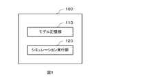
- FIG. 1 is a diagram illustrating a configuration of a circuit simulation apparatus 100 according to an embodiment of the present invention.
- the circuit simulation apparatus 100 includes a model storage unit 110 and a simulation execution unit 120.
- the model storage unit 110 stores a nonlinear equivalent circuit model of a capacitor and an inductor.
- the nonlinear equivalent circuit model is provided from an electronic component manufacturer as data in a format suitable for the circuit simulation apparatus 100 and stored in the model storage unit 110, for example.
- the nonlinear equivalent circuit model considers a plurality of factors that affect the characteristics of the capacitor and the inductor.
- the plurality of factors include, for example, temperature, DC bias (DC voltage or DC current), AC amplitude (AC voltage or AC current), characteristic variation, and the like.
- the simulation execution unit 120 uses the nonlinear equivalent circuit model stored in the model storage unit 110 to simulate the nonlinear characteristics of the capacitor or inductor according to a plurality of factors.
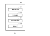
- FIG. 2 is a diagram illustrating an example of functional blocks of a nonlinear equivalent circuit model.
- the nonlinear equivalent circuit model 200 includes a passive circuit element 210, a factor specifying unit 220, a characteristic information storage unit 230, and a control element 240.
- the passive circuit element 210 is an element that represents an equivalent circuit of a capacitor or an inductor, and includes, for example, a resistance element, a capacitance element, and an inductance element.
- the factor identifying unit 220 identifies a plurality of factor values that affect the characteristics of the capacitor or inductor.
- the factor specifying unit 220 can specify the value of the factor by user input, for example.
- the factor specifying unit 220 may specify values such as a DC bias and an AC amplitude from a circuit diagram input to the circuit simulation device 100, for example.
- the characteristic information storage unit 230 stores characteristic information indicating the correspondence between possible values of a plurality of factors and the characteristics of the passive circuit elements.
- the characteristic information is, for example, a function of the characteristic of the passive circuit element having a plurality of factors as variables. Specifically, the function is, for example, an approximate function of the rate of change of the characteristics of the passive circuit element generated based on the measured value of the characteristics of the passive circuit element in accordance with changes in a plurality of factors. Details of the approximate function will be described later.
- the characteristic information is not limited to a function.
- the characteristic information is information (for example, table information) in which a plurality of possible values of a plurality of factors are associated with characteristics of the passive circuit element for each of the plurality of possible values. There may be.
- the control element 240 is an element for considering the characteristics of the passive circuit element that changes according to a plurality of factors.
- the control element 240 for example, has a characteristic current that flows through the passive circuit element when a plurality of factors are specified values, and a passive circuit element when the plurality of factors are predetermined values (initial values). This is a current source that generates a differential current from the flowing initial current.
- the control element 240 has, for example, a characteristic voltage generated in the passive circuit element when a plurality of factors are specified values, and an initial voltage generated in the passive circuit element when the plurality of factors are predetermined values (initial values). Is a voltage source that generates a differential voltage.
- FIG. 3 is a diagram illustrating an example of a nonlinear equivalent circuit model of a capacitor.
- the non-linear equivalent circuit model of the capacitor includes an equivalent circuit 300 of the capacitor represented by passive circuit elements (resistance element R, capacitance element C, and inductance element L).
- the nonlinear equivalent circuit model of the capacitor includes a current source I (control element) connected in parallel to a passive circuit element whose characteristics change according to a plurality of factors.
- n (1... N) indicates an element position. Each element is given an element position as a subscript.
- passive circuit elements whose characteristics do not change according to a plurality of factors are represented by lowercase letters (c, r, and l).
- the current source I In the nonlinear equivalent circuit model of the capacitor, the current source I generates a differential current between a characteristic current flowing through the passive circuit element and an initial current when a plurality of factors have specified values.
- the current source I 1 has a sum of the current flowing through the capacitive element C 1 and the current flowing through the resistance element R 1 (characteristic current) when a plurality of factors are specified, and the plurality of factors have initial values.
- a difference current between the current flowing through the capacitive element C 1 and the current flowing through the resistance element R 1 (initial current) is generated.
- the nonlinear characteristics of the capacitor according to a plurality of factors are simulated.
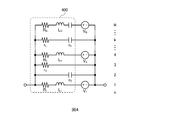
- FIG. 4 is a diagram illustrating an example of a nonlinear equivalent circuit model of an inductor.
- the nonlinear equivalent circuit model of the inductor includes an inductor equivalent circuit 400 represented by passive circuit elements (resistance element R, capacitance element C, and inductance element L).
- the nonlinear equivalent circuit model of the inductor includes a voltage source V (control element) connected in series to a passive circuit element whose characteristics change according to a plurality of factors.
- n (1... N) indicates an element position. Each element is given an element position as a subscript.
- passive circuit elements whose characteristics do not change according to a plurality of factors are represented by lowercase letters (c, r, and l).
- the voltage source V generates a differential voltage between the characteristic voltage generated in the passive circuit element and the initial voltage when a plurality of factors have specified values.
- the voltage source V 1 has a total (characteristic voltage) of the voltage generated in the resistance element R 1 and the voltage generated in the inductance element L 1 when a plurality of factors are specified values, and the plurality of factors have initial values.
- a difference voltage between the sum (initial voltage) of the voltage generated in the resistance element R 1 and the voltage generated in the inductance element L 1 is generated.
- the nonlinear characteristics of the inductor corresponding to a plurality of factors are simulated.
- the plurality of factors are x 1 , x 2 ,...,
- the resistance element at element position n the characteristics of the capacitive element and the inductance element according to the plurality of factors are R n , C n and L n , and the plurality of factors are initial values.
- the characteristics of the capacitive element and the inductance element in this case are R 0n , C 0n, and L 0n
- the change rate of the characteristics is expressed by the following equations (1) to (3).
- the first term of the equations (1) to (3) is 1 when all the variables (x 1 , x 2 ,%) Match the initial values, and the rate of change is zero.
- the factors are assumed to be two variables x 1 and x 2 and their initial values are assumed to be x 10 and x 20 .
- x 1 is temperature
- x 2 is DC voltage (or DC current)
- x 10 is 25 ° C.
- x 20 is 0V (or 0A).
- equations (1) to (3) are simplified to the following equations (4) to (6).
- the first term of the equations (4) to (6) is defined by the following equations (7) to (9).
- Equation (7) to (9) are simply expressed as k (x 1 , x 2 ) below.
- the function k (x 1 , x 2 ) is 1 when the two variables (x 1 , x 2 ) are the initial values (x 10 , x 20 ), and the characteristics of the passive circuit elements are always positive. Therefore, it is defined by the following formula (10).
- the function f (x 1 , x 2 ) is zero when the two variables (x 1 , x 2 ) are the initial values (x 10 , x 20 ).
- the function f (x 1 , x 2 ) is expressed by the following equation (11) by, for example, expansion by power.
- Equation (11) b 10 , b 10 ,..., B n1, n2 are real number expansion coefficients, and n 1 , n 2 are the maximum orders of x 1 , x 2 , respectively.
- the function f (x 1 , x 2 ) can also be expressed by the following equation (12) by expansion using the basis function g ij (x 1 , x 2 ) for the purpose of improving convergence.
- b 10 , b 01 ,..., B mn are expansion coefficients of basis functions. If the basis function is defined by the following equation (13), it matches the equation (11) developed by power.
- c 1, ij and C 2, ij are constants for making basis functions having different orders (i, j) linearly independent from each other.
- an approximate function (characteristic information) of the rate of change of the characteristics of the passive circuit element according to a plurality of factors can be obtained.
- the values of a plurality of factors that affect the characteristics of the capacitor are specified. Then, based on the specified values of the plurality of factors and the characteristic information indicating the characteristic change of the passive circuit element, the difference is caused by the current source connected in parallel to the passive circuit element whose characteristics change according to the plurality of factors. A current is generated. Thereby, the nonlinear characteristic of the capacitor according to a plurality of factors is simulated.
- the values of a plurality of factors that affect the characteristics of the inductor are specified. Then, based on the specified values of the plurality of factors and the characteristic information indicating the characteristic change of the passive circuit element, the difference is caused by the voltage source connected in series to the passive circuit element whose characteristics change according to the plurality of factors. A voltage is generated. Thereby, the nonlinear characteristic of the inductor according to a plurality of factors is simulated.
- the characteristic information indicating the characteristic change of the passive circuit element can be expressed as a function of the characteristic of the passive circuit element having a plurality of factors as variables, for example. By using such a function, it is possible to calculate the characteristic value of the passive circuit element corresponding to various values of a plurality of factors. Therefore, simulations with various values of a plurality of factors are possible.
- the characteristic information indicating the characteristic change of the passive circuit element includes, for example, a plurality of possible values of a plurality of factors and a characteristic of the passive circuit element for each of the plurality of possible values. Can be represented as information (for example, table information). By using such information, it is not necessary to calculate a complicated function, and the simulation processing time can be reduced.
- each embodiment described above is for facilitating the understanding of the present invention, and is not intended to limit the present invention.
- the present invention can be changed / improved without departing from the spirit thereof, and the present invention includes equivalents thereof.
- those obtained by appropriately modifying the design of each embodiment by those skilled in the art are also included in the scope of the present invention as long as they include the features of the present invention.
- each element included in each embodiment and its arrangement, material, condition, shape, size, and the like are not limited to those illustrated, and can be changed as appropriate.
- each element included in each embodiment can be combined as much as technically possible, and combinations thereof are included in the scope of the present invention as long as they include the features of the present invention.
Landscapes
- Engineering & Computer Science (AREA)
- Power Engineering (AREA)
- Physics & Mathematics (AREA)
- Theoretical Computer Science (AREA)
- Manufacturing & Machinery (AREA)
- Computer Hardware Design (AREA)
- Evolutionary Computation (AREA)
- Geometry (AREA)
- General Engineering & Computer Science (AREA)
- General Physics & Mathematics (AREA)
- Microelectronics & Electronic Packaging (AREA)
- Filters And Equalizers (AREA)
Abstract
様々な要因を考慮した回路シミュレーションを行う。受動回路素子により表されたコンデンサの等価回路を用いてコンデンサの特性をコンピュータによってシミュレートする回路シミュレーション方法であって、コンピュータは、コンデンサの特性に影響を与える複数の要因の値を特定し、特定された複数の要因の値と、複数の要因の取り得る値と受動回路素子の特性との対応関係を示す特性情報とに基づいて、複数の要因に応じて特性が変化する受動回路素子に並列に接続される制御素子により、複数の要因が特定された値の場合に受動回路素子に流れる特性電流と複数の要因が所定の値の場合に受動回路素子に流れる初期電流との差分電流を生成させ、初期電流に差分電流を加算することで、複数の要因に応じたコンデンサの非線形特性をシミュレートする。
Description
本発明は、回路シミュレーション方法及び回路シミュレーション装置に関する。
受動回路素子により表された等価回路を用いてコンデンサやインダクタの特性をシミュレートする手法が知られている(例えば、特許文献1及び2)。
例えば、特許文献1には、実測値をもとに電圧を変数として表された近似関数により算出される直流電圧印加時における受動回路素子の特性変化率に基づいて、直流電圧印加時のコンデンサの非線形特性をシミュレーションする手法が開示されている。また例えば、特許文献2には、実測値をもとに電流を変数として表された近似関数により算出される直流電流重畳時における受動回路素子の特性変化率に基づいて、直流電流重畳時のインダクタの非線形特性をシミュレーションする手法が開示されている。
特許文献1及び2に開示されている手法では、直流電圧又は直流電流を考慮することにより、回路シミュレーションの精度を向上させることが可能である。
ところで、コンデンサやインダクタの特性は、直流電圧や直流電流だけではなく、温度や特性ばらつき、交流電圧、交流電流等の様々な要因によって変化し得る。しかしながら、特許文献1及び2に開示されている手法では、特性を変化させる要因として、直流電圧又は直流電流しか考慮されていない。
本発明はこのような事情に鑑みてなされたものであり、様々な要因を考慮した回路シミュレーションが可能な回路シミュレーション方法及び回路シミュレーション装置を提供することを目的とする。
本発明の一態様に係る回路シミュレーション方法は、受動回路素子により表されたコンデンサの等価回路を用いてコンデンサの特性をコンピュータによってシミュレートする回路シミュレーション方法であって、コンピュータは、コンデンサの特性に影響を与える複数の要因の値を特定し、特定された複数の要因の値と、複数の要因の取り得る値と受動回路素子の特性との対応関係を示す特性情報とに基づいて、複数の要因に応じて特性が変化する受動回路素子に並列に接続される制御素子により、複数の要因が特定された値の場合に受動回路素子に流れる特性電流と複数の要因が所定の値の場合に受動回路素子に流れる初期電流との差分電流を生成させ、初期電流に差分電流を加算することで、複数の要因に応じたコンデンサの非線形特性をシミュレートする。
また、本発明の一態様に係る回路シミュレーション方法は、受動回路素子により表されたインダクタの等価回路を用いてインダクタの特性をコンピュータによってシミュレートする回路シミュレーション方法であって、コンピュータは、インダクタの特性に影響を与える複数の要因の値を特定し、特定された複数の要因の値と、複数の要因の取り得る値と受動回路素子の特性との対応関係を示す特性情報とに基づいて、複数の要因に応じて特性が変化する受動回路素子に直列に接続される制御素子により、複数の要因が特定された値の場合に受動回路素子に生じる特性電圧と複数の要因が所定の値の場合に受動回路素子に生じる初期電圧との差分電圧を生成させ、初期電圧に差分電圧を加算することで、複数の要因に応じたインダクタの非線形特性をシミュレートする。
また、本発明の一態様に係る回路シミュレーション装置は、コンデンサの等価回路を表す受動回路素子と、コンデンサの特性に影響を与える複数の要因の値を特定する要因特定部と、複数の要因の取り得る値と受動回路素子の特性との対応関係を示す特性情報を記憶する特性情報記憶部と、複数の要因に応じて特性が変化する受動回路素子に並列に接続される制御素子であって、特定された複数の要因の値及び特性情報に基づいて、複数の要因が特定された値の場合に受動回路素子に流れる特性電流と複数の要因が所定の値の場合に受動回路素子に流れる初期電流との差分電流を生成する制御素子と、を含むコンデンサの非線形等価回路モデルを記憶するモデル記憶部と、非線形等価回路モデルを用いて、複数の要因に応じたコンデンサの非線形特性をシミュレートするシミュレーション実行部と、を備える。
また、本発明の一態様に係る回路シミュレーション装置は、インダクタの等価回路を表す受動回路素子と、インダクタの特性に影響を与える複数の要因の値を特定する要因特定部と、複数の要因の取り得る値と受動回路素子の特性との対応関係を示す特性情報を記憶する特性情報記憶部と、複数の要因に応じて特性が変化する受動回路素子に直列に接続される制御素子であって、特定された複数の要因の値及び特性情報に基づいて、複数の要因が特定された値の場合に受動回路素子に生じる特性電圧と複数の要因が所定の値の場合に受動回路素子に生じる初期電圧との差分電圧を生成する制御素子と、を含むインダクタの非線形等価回路モデルを記憶するモデル記憶部と、非線形等価回路モデルを用いて、複数の要因に応じたインダクタの非線形特性をシミュレートするシミュレーション実行部と、を備える。
本発明によれば、様々な要因を考慮した回路シミュレーションが可能な回路シミュレーション方法及び回路シミュレーション装置を提供することが可能となる。
以下、図面を参照して本発明の一実施形態について説明する。図1は、本発明の一実施形態である回路シミュレーション装置100の構成を示す図である。回路シミュレーション装置100は、モデル記憶部110及びシミュレーション実行部120を備える。
モデル記憶部110は、コンデンサ及びインダクタの非線形等価回路モデルを記憶する。非線形等価回路モデルは、例えば、回路シミュレーション装置100に適した形式のデータとして電子部品メーカーから提供され、モデル記憶部110に格納される。非線形等価回路モデルは、コンデンサ及びインダクタの特性に影響を与える複数の要因を考慮したものである。複数の要因は、例えば、温度、DCバイアス(直流電圧又は直流電流)、AC振幅(交流電圧又は交流電流)、特性ばらつき等を含む。
シミュレーション実行部120は、モデル記憶部110に格納されている非線形等価回路モデルを用いて、複数の要因に応じたコンデンサ又はインダクタの非線形特性をシミュレートする。
図2は、非線形等価回路モデルの機能ブロックの一例を示す図である。図2に示すように、非線形等価回路モデル200は、受動回路素子210、要因特定部220、特性情報記憶部230及び制御素子240を備える。
受動回路素子210は、コンデンサ又はインダクタの等価回路を表す素子であり、例えば、抵抗素子、容量素子及びインダクタンス素子を含む。
要因特定部220は、コンデンサ又はインダクタの特性に影響を与える複数の要因の値を特定する。要因特定部220は、例えば、ユーザ入力によって要因の値を特定することができる。また、要因特定部220は、例えば、回路シミュレーション装置100に入力された回路図から、DCバイアスやAC振幅等の値を特定してもよい。
特性情報記憶部230は、複数の要因の取り得る値と受動回路素子の特性との対応関係を示す特性情報を記憶する。特性情報は、例えば、複数の要因を変数とする受動回路素子の特性の関数である。具体的には、関数は、例えば、複数の要因の変化に応じた受動回路素子の特性の実測値に基づいて生成された、受動回路素子の特性の変化率の近似関数である。近似関数の詳細については後述する。なお、特性情報は、関数に限られず、例えば、複数の要因の複数の取り得る値と、複数の取り得る値のそれぞれに対する受動回路素子の特性とを対応づけた情報(例えば、テーブル情報)であってもよい。
制御素子240は、複数の要因に応じて変化する受動回路素子の特性を考慮するための素子である。具体的には、制御素子240は、例えば、複数の要因が特定された値の場合に受動回路素子に流れる特性電流と、複数の要因が所定の値(初期値)の場合に受動回路素子に流れる初期電流との差分電流を生成する電流源である。また、制御素子240は、例えば、複数の要因が特定された値の場合に受動回路素子に生じる特性電圧と、複数の要因が所定の値(初期値)の場合に受動回路素子に生じる初期電圧との差分電圧を生成する電圧源である。
図3は、コンデンサの非線形等価回路モデルの一例を示す図である。図3に示すように、コンデンサの非線形等価回路モデルは、受動回路素子(抵抗素子R、容量素子C及びインダクタンス素子L)によって表される、コンデンサの等価回路300を備える。また、コンデンサの非線形等価回路モデルは、複数の要因に応じて特性が変化する受動回路素子に並列に接続される電流源I(制御素子)を備える。なお、図3において、n(1…N)は、素子位置を示している。各素子には、素子位置が添え字として付されている。例えば、素子位置n=1の容量素子、抵抗素子及び電流源は、C1、R1及びI1と表されている。なお、複数の要因に応じて特性が変化しない受動回路素子は、小文字(c、r及びl(エル))で表されている。
コンデンサの非線形等価回路モデルにおいて、電流源Iは、複数の要因が特定された値の場合に受動回路素子に流れる特性電流と初期電流との差分電流を生成する。例えば、電流源I1は、複数の要因が特定された値の場合に容量素子C1を流れる電流と抵抗素子R1を流れる電流との合計(特性電流)と、複数の要因が初期値の場合に容量素子C1を流れる電流と抵抗素子R1を流れる電流との合計(初期電流)との差分電流を生成する。このように、電流源Iによって生成された差分電流を初期電流に加算することにより、複数の要因に応じたコンデンサの非線形特性がシミュレートされる。
図4は、インダクタの非線形等価回路モデルの一例を示す図である。図4に示すように、インダクタの非線形等価回路モデルは、受動回路素子(抵抗素子R、容量素子C及びインダクタンス素子L)によって表される、インダクタの等価回路400を備える。また、インダクタの非線形等価回路モデルは、複数の要因に応じて特性が変化する受動回路素子に直列に接続される電圧源V(制御素子)を備える。なお、図4において、n(1…N)は、素子位置を示している。各素子には、素子位置が添え字として付されている。例えば、素子位置n=1の抵抗素子、インダクタンス素子及び電圧源は、R1、L1及びV1と表されている。なお、複数の要因に応じて特性が変化しない受動回路素子は、小文字(c、r及びl(エル))で表されている。
インダクタの非線形等価回路モデルにおいて、電圧源Vは、複数の要因が特定された値の場合に受動回路素子に生じる特性電圧と初期電圧との差分電圧を生成する。例えば、電圧源V1は、複数の要因が特定された値の場合に抵抗素子R1に生じる電圧とインダクタンス素子L1に生じる電圧との合計(特性電圧)と、複数の要因が初期値の場合に抵抗素子R1に生じる電圧とインダクタンス素子L1に生じる電圧との合計(初期電圧)との差分電圧を生成する。このように、電圧源Vによって生成された差分電圧を初期電圧に加算することにより、複数の要因に応じたインダクタの非線形特性がシミュレートされる。
特性情報記憶部230に記憶される特性情報である、受動回路素子の特性の変化率の近似関数の一例について説明する。
複数の要因をx1,x2,…、素子位置nの抵抗素子、複数の要因に応じた容量素子及びインダクタンス素子の特性をそれぞれRn、Cn及びLn、複数の要因が初期値の場合の容量素子及びインダクタンス素子の特性をそれぞれR0n、C0n及びL0nとすると、特性の変化率は以下の式(1)~(3)により表される。



式(1)~(3)の第1項は、全ての変数(x1,x2,…)が初期値と一致する場合に1となり、変化率はゼロとなる。
ここで、説明を簡単にするために、要因を2つの変数x1,x2とし、それらの初期値をx10,x20として説明する。例えば、x1は温度、x2は直流電圧(又は直流電流)、x10は25℃、x20は0V(又は0A)である。この場合、式(1)~(3)は、以下の式(4)~(6)に簡略化される。



式(4)~(6)の第1項を以下の式(7)~(9)で定義する。



式(7)~(9)をまとめて説明するために、以下では、式(7)~(9)を単純にk(x1,x2)と表す。関数k(x1,x2)は、2つの変数(x1,x2)が初期値(x10,x20)となる場合に1となり、また、受動回路素子の特性は常に正であるから、以下の式(10)で定義される。

関数f(x1,x2)は、2つの変数(x1,x2)が初期値(x10,x20)となる場合にゼロとなる。関数f(x1,x2)は、例えば、べき乗による展開により、以下の式(11)で表される。

式(11)において、b10,b10,…,bn1,n2は実数の展開係数であり、n1,n2はそれぞれx1,x2の最大次数である。
また、関数f(x1,x2)は、収束性の改善を目的として、基底関数gij(x1,x2)を用いた展開により、以下の式(12)で表すこともできる。
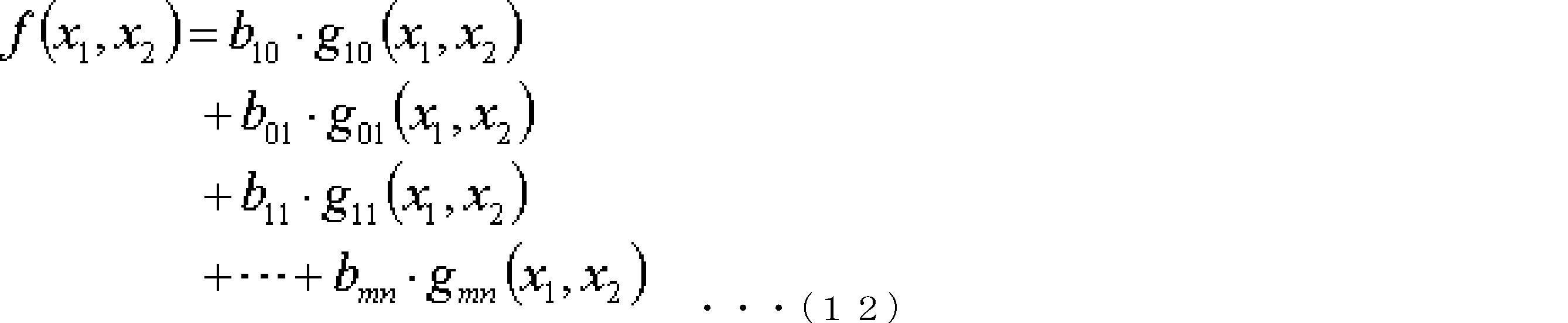
ここで、b10,b01,…,bmnは、基底関数の展開係数である。基底関数を以下の式(13)で定義すると、べき乗により展開した式(11)に一致する。

基底関数gij(x1,x2)を以下の式(14)~(17)で定義すると、変数(x1,x2)に大きな値が入力された場合も有限な定数となるため、計算の収束性において有効である。




ここで、c1,ij,C2,ijは、次数(i,j)が異なる基底関数を互いに一次独立とするための定数である。
以上のように、複数の要因に応じた受動回路素子の特性の変化率の近似関数(特性情報)を求めることができる。そして、本実施形態の回路シミュレーション装置100では、コンデンサの特性に影響を与える複数の要因の値が特定される。そして、特定された複数の要因の値と、受動回路素子の特性変化を示す特性情報とに基づいて、複数の要因に応じて特性が変化する受動回路素子に並列に接続される電流源によって差分電流が生成される。これにより、複数の要因に応じたコンデンサの非線形特性がシミュレートされる。
また、本実施形態の回路シミュレーション装置100では、インダクタの特性に影響を与える複数の要因の値が特定される。そして、特定された複数の要因の値と、受動回路素子の特性変化を示す特性情報とに基づいて、複数の要因に応じて特性が変化する受動回路素子に直列に接続される電圧源によって差分電圧が生成される。これにより、複数の要因に応じたインダクタの非線形特性がシミュレートされる。
また、本実施形態の回路シミュレーション装置100では、受動回路素子の特性変化を示す特性情報は、例えば、複数の要因を変数とする受動回路素子の特性の関数として表すことができる。このような関数を用いることにより、複数の要因の様々な値に対応する受動回路素子の特性の値を算出することが可能となる。したがって、複数の要因の様々な値におけるシミュレーションが可能となる。
また、本実施形態の回路シミュレーション装置100では、受動回路素子の特性変化を示す特性情報は、例えば、複数の要因の複数の取り得る値と、複数の取り得る値のそれぞれに対する受動回路素子の特性とを対応づけた情報(例えば、テーブル情報)として表すことができる。このような情報を用いることにより、複雑な関数の計算が不要となり、シミュレーションの処理時間を削減することが可能となる。
以上説明した各実施形態は、本発明の理解を容易にするためのものであり、本発明を限定して解釈するためのものではない。本発明は、その趣旨を逸脱することなく、変更/改良され得るととともに、本発明にはその等価物も含まれる。即ち、各実施形態に当業者が適宜設計変更を加えたものも、本発明の特徴を備えている限り、本発明の範囲に包含される。例えば、各実施形態が備える各要素およびその配置、材料、条件、形状、サイズなどは、例示したものに限定されるわけではなく適宜変更することができる。また、各実施形態が備える各要素は、技術的に可能な限りにおいて組み合わせることができ、これらを組み合わせたものも本発明の特徴を含む限り本発明の範囲に包含される。
100
回路シミュレーション装置、110
モデル記憶部、120
シミュレーション実行部、200
非線形等価回路モデル、210
受動回路素子、220
要因特定部、230
特性情報記憶部、240
制御素子、300,400
等価回路
回路シミュレーション装置、110
モデル記憶部、120
シミュレーション実行部、200
非線形等価回路モデル、210
受動回路素子、220
要因特定部、230
特性情報記憶部、240
制御素子、300,400
等価回路
Claims (6)
- 受動回路素子により表されたコンデンサの等価回路を用いて前記コンデンサの特性をコンピュータによってシミュレートする回路シミュレーション方法であって、
前記コンピュータは、
前記コンデンサの特性に影響を与える複数の要因の値を特定し、
前記特定された複数の要因の値と、前記複数の要因の取り得る値と前記受動回路素子の特性との対応関係を示す特性情報とに基づいて、前記複数の要因に応じて特性が変化する前記受動回路素子に並列に接続される制御素子により、前記複数の要因が前記特定された値の場合に前記受動回路素子に流れる特性電流と前記複数の要因が所定の値の場合に前記受動回路素子に流れる初期電流との差分電流を生成させ、前記初期電流に前記差分電流を加算することで、
前記複数の要因に応じた前記コンデンサの非線形特性をシミュレートする、
回路シミュレーション方法。 - 受動回路素子により表されたインダクタの等価回路を用いて前記インダクタの特性をコンピュータによってシミュレートする回路シミュレーション方法であって、
前記コンピュータは、
前記インダクタの特性に影響を与える複数の要因の値を特定し、
前記特定された複数の要因の値と、前記複数の要因の取り得る値と前記受動回路素子の特性との対応関係を示す特性情報とに基づいて、前記複数の要因に応じて特性が変化する前記受動回路素子に直列に接続される制御素子により、前記複数の要因が前記特定された値の場合に前記受動回路素子に生じる特性電圧と前記複数の要因が所定の値の場合に前記受動回路素子に生じる初期電圧との差分電圧を生成させ、前記初期電圧に前記差分電圧を加算することで、
前記複数の要因に応じた前記インダクタの非線形特性をシミュレートする、
回路シミュレーション方法。 - 前記特性情報は、前記複数の要因を変数とする前記受動回路素子の特性の関数である、
請求項1又は2に記載の回路シミュレーション方法。 - 前記特性情報は、前記複数の要因の複数の取り得る値と、前記複数の取り得る値のそれぞれに対する前記受動回路素子の特性とを対応づけた情報である、
請求項1又は2に記載の回路シミュレーション方法。 - コンデンサの等価回路を表す受動回路素子と、
前記コンデンサの特性に影響を与える複数の要因の値を特定する要因特定部と、
前記複数の要因の取り得る値と前記受動回路素子の特性との対応関係を示す特性情報を記憶する特性情報記憶部と、
前記複数の要因に応じて特性が変化する前記受動回路素子に並列に接続される制御素子であって、前記特定された複数の要因の値及び前記特性情報に基づいて、前記複数の要因が前記特定された値の場合に前記受動回路素子に流れる特性電流と前記複数の要因が所定の値の場合に前記受動回路素子に流れる初期電流との差分電流を生成する制御素子と、
を含むコンデンサの非線形等価回路モデルを記憶するモデル記憶部と、
前記非線形等価回路モデルを用いて、前記複数の要因に応じた前記コンデンサの非線形特性をシミュレートするシミュレーション実行部と、
を備える回路シミュレーション装置。 - インダクタの等価回路を表す受動回路素子と、
前記インダクタの特性に影響を与える複数の要因の値を特定する要因特定部と、
前記複数の要因の取り得る値と前記受動回路素子の特性との対応関係を示す特性情報を記憶する特性情報記憶部と、
前記複数の要因に応じて特性が変化する前記受動回路素子に直列に接続される制御素子であって、前記特定された複数の要因の値及び前記特性情報に基づいて、前記複数の要因が前記特定された値の場合に前記受動回路素子に生じる特性電圧と前記複数の要因が所定の値の場合に前記受動回路素子に生じる初期電圧との差分電圧を生成する制御素子と、
を含むインダクタの非線形等価回路モデルを記憶するモデル記憶部と、
前記非線形等価回路モデルを用いて、前記複数の要因に応じた前記インダクタの非線形特性をシミュレートするシミュレーション実行部と、
を備える回路シミュレーション装置。
Applications Claiming Priority (2)
| Application Number | Priority Date | Filing Date | Title |
|---|---|---|---|
| JP2016-227790 | 2016-11-24 | ||
| JP2016227790 | 2016-11-24 |
Publications (1)
| Publication Number | Publication Date |
|---|---|
| WO2018096765A1 true WO2018096765A1 (ja) | 2018-05-31 |
Family
ID=62195784
Family Applications (1)
| Application Number | Title | Priority Date | Filing Date |
|---|---|---|---|
| PCT/JP2017/032740 Ceased WO2018096765A1 (ja) | 2016-11-24 | 2017-09-12 | 回路シミュレーション方法及び回路シミュレーション装置 |
Country Status (1)
| Country | Link |
|---|---|
| WO (1) | WO2018096765A1 (ja) |
Cited By (1)
| Publication number | Priority date | Publication date | Assignee | Title |
|---|---|---|---|---|
| CN111079364A (zh) * | 2019-11-25 | 2020-04-28 | 上海科梁信息工程股份有限公司 | 一种直流变压器的仿真方法、仿真平台及可读存储介质 |
-
2017
- 2017-09-12 WO PCT/JP2017/032740 patent/WO2018096765A1/ja not_active Ceased
Non-Patent Citations (3)
| Title |
|---|
| "Radio-Wave Newspaper second part: High -Technology in special edition (non-official translation)", vol. 1445, 18 August 2016, MURATA MFG.CO.,LTD, article HIDAKA, SEIJI: "Dynamic model of laminated ceramic capacitor, and evolutional circuit simulation", pages: 8,9 * |
| MURATA MANUFACTURING CO LTD., 8 September 2015 (2015-09-08), pages 1 - 22, Retrieved from the Internet <URL:http://web.archive.org/web/20150908080605/http://www.murata.com/~/media/webrenewal/tool/library/pspice/note_dynamic-model_mi101e.ashx?la=en> [retrieved on 20171108] * |
| MURATA MFG.CO., LTD: "(non-official translation) Regarding dynamic model of power inductor and dielectric chip laminated capacitor", 11 September 2015 (2015-09-11), pages 1 - 22, Retrieved from the Internet <URL:http://web.archive.org/web/20150911010515/http://www.murata.com/~/media/webrenewal/tool/library/pspice/note_dynamic-model_mi101j.ashx?la=ja-jp> [retrieved on 20171108] * |
Cited By (2)
| Publication number | Priority date | Publication date | Assignee | Title |
|---|---|---|---|---|
| CN111079364A (zh) * | 2019-11-25 | 2020-04-28 | 上海科梁信息工程股份有限公司 | 一种直流变压器的仿真方法、仿真平台及可读存储介质 |
| CN111079364B (zh) * | 2019-11-25 | 2023-07-14 | 上海科梁信息科技股份有限公司 | 一种直流变压器的仿真方法、仿真平台及可读存储介质 |
Similar Documents
| Publication | Publication Date | Title |
|---|---|---|
| Wang et al. | Design of a memcapacitor emulator based on a memristor | |
| Elwy et al. | All possible topologies of the fractional-order Wien oscillator family using different approximation techniques | |
| CN102970647B (zh) | 一种扬声器振动中非线性特性的仿真计算方法 | |
| CN103282904B (zh) | 等效电路模型,程序以及存储介质 | |
| Jakubowska et al. | Analysis of the transient state in a series circuit of the class RL β C α | |
| US20160070837A1 (en) | Inductor simulation method and inductor nonlinear equivalent circuit model | |
| Biolek et al. | Analog emulator of genuinely floating memcapacitor with piecewise-linear constitutive relation | |
| KR20100080357A (ko) | 전류 모드에서 동작하는 전자 장치를 타겟 기술로 이동시키는 방법 | |
| JP7512229B2 (ja) | 情報処理装置、情報処理方法及びプログラム | |
| Bartiromo et al. | Electrical measurements in the laboratory practice | |
| Majka | Fractional derivative approach in modeling of a nonlinear coil for ferroresonance analyses | |
| Kapoulea et al. | Realizations of simple fractional-order capacitor emulators with electronically-tunable capacitance | |
| WO2018096765A1 (ja) | 回路シミュレーション方法及び回路シミュレーション装置 | |
| Saha et al. | Effect of initialization on a class of fractional order systems: experimental verification and dependence on nature of past history and system parameters | |
| Gazda et al. | Harmonic balance surrogate-based immunity modeling of a nonlinear analog circuit | |
| JP2017068492A (ja) | 半導体集積回路の設計支援装置、半導体集積回路の不要輻射の対策方法、コンピュータプログラム | |
| WO2018096766A1 (ja) | 回路シミュレーション方法及び回路シミュレーション装置 | |
| US20150193565A1 (en) | Method of simulating output of nonlinear dynamical system in an event driven way | |
| Eddy et al. | Redesign driven by manufacturing data for next-generation modernization of legacy products | |
| CN110427644A (zh) | 一种电力仿真系统的状态方程列写方法和系统 | |
| Nahvi et al. | Adaptive sampling of nonlinear system trajectory for model order reduction | |
| Holmes | Guitar effects: pedal emulation and identification | |
| CN102224501A (zh) | 模拟设备、模拟方法、以及存储程序的记录介质 | |
| CN105453088B (zh) | 考虑到施加交流电压的电容器的静电电容值决定方法及程序 | |
| Naeem et al. | Applying homotopy type techniques to higher order boundary value problems |
Legal Events
| Date | Code | Title | Description |
|---|---|---|---|
| 121 | Ep: the epo has been informed by wipo that ep was designated in this application |
Ref document number: 17873979 Country of ref document: EP Kind code of ref document: A1 |
|
| NENP | Non-entry into the national phase |
Ref country code: DE |
|
| 122 | Ep: pct application non-entry in european phase |
Ref document number: 17873979 Country of ref document: EP Kind code of ref document: A1 |
|
| NENP | Non-entry into the national phase |
Ref country code: JP |