WO2018092235A1 - ステープラ - Google Patents
ステープラ Download PDFInfo
- Publication number
- WO2018092235A1 WO2018092235A1 PCT/JP2016/084074 JP2016084074W WO2018092235A1 WO 2018092235 A1 WO2018092235 A1 WO 2018092235A1 JP 2016084074 W JP2016084074 W JP 2016084074W WO 2018092235 A1 WO2018092235 A1 WO 2018092235A1
- Authority
- WO
- WIPO (PCT)
- Prior art keywords
- pusher
- driving force
- staple
- stapler
- pushers
- Prior art date
- Legal status (The legal status is an assumption and is not a legal conclusion. Google has not performed a legal analysis and makes no representation as to the accuracy of the status listed.)
- Ceased
Links
Images






Classifications
-
- A—HUMAN NECESSITIES
- A61—MEDICAL OR VETERINARY SCIENCE; HYGIENE
- A61B—DIAGNOSIS; SURGERY; IDENTIFICATION
- A61B17/00—Surgical instruments, devices or methods
- A61B17/11—Surgical instruments, devices or methods for performing anastomosis; Buttons for anastomosis
- A61B17/115—Staplers for performing anastomosis, e.g. in a single operation
- A61B17/1155—Circular staplers comprising a plurality of staples
-
- A—HUMAN NECESSITIES
- A61—MEDICAL OR VETERINARY SCIENCE; HYGIENE
- A61B—DIAGNOSIS; SURGERY; IDENTIFICATION
- A61B17/00—Surgical instruments, devices or methods
- A61B17/068—Surgical staplers, e.g. containing multiple staples or clamps
- A61B17/072—Surgical staplers, e.g. containing multiple staples or clamps for applying a row of staples in a single action, e.g. the staples being applied simultaneously
-
- A—HUMAN NECESSITIES
- A61—MEDICAL OR VETERINARY SCIENCE; HYGIENE
- A61B—DIAGNOSIS; SURGERY; IDENTIFICATION
- A61B17/00—Surgical instruments, devices or methods
- A61B17/068—Surgical staplers, e.g. containing multiple staples or clamps
- A61B17/072—Surgical staplers, e.g. containing multiple staples or clamps for applying a row of staples in a single action, e.g. the staples being applied simultaneously
- A61B17/07207—Surgical staplers, e.g. containing multiple staples or clamps for applying a row of staples in a single action, e.g. the staples being applied simultaneously the staples being applied sequentially
-
- A—HUMAN NECESSITIES
- A61—MEDICAL OR VETERINARY SCIENCE; HYGIENE
- A61B—DIAGNOSIS; SURGERY; IDENTIFICATION
- A61B17/00—Surgical instruments, devices or methods
- A61B17/068—Surgical staplers, e.g. containing multiple staples or clamps
-
- A—HUMAN NECESSITIES
- A61—MEDICAL OR VETERINARY SCIENCE; HYGIENE
- A61B—DIAGNOSIS; SURGERY; IDENTIFICATION
- A61B17/00—Surgical instruments, devices or methods
- A61B2017/00017—Electrical control of surgical instruments
-
- A—HUMAN NECESSITIES
- A61—MEDICAL OR VETERINARY SCIENCE; HYGIENE
- A61B—DIAGNOSIS; SURGERY; IDENTIFICATION
- A61B17/00—Surgical instruments, devices or methods
- A61B2017/00367—Details of actuation of instruments, e.g. relations between pushing buttons, or the like, and activation of the tool, working tip, or the like
- A61B2017/00398—Details of actuation of instruments, e.g. relations between pushing buttons, or the like, and activation of the tool, working tip, or the like using powered actuators, e.g. stepper motors, solenoids
-
- A—HUMAN NECESSITIES
- A61—MEDICAL OR VETERINARY SCIENCE; HYGIENE
- A61B—DIAGNOSIS; SURGERY; IDENTIFICATION
- A61B17/00—Surgical instruments, devices or methods
- A61B2017/00681—Aspects not otherwise provided for
- A61B2017/00734—Aspects not otherwise provided for battery operated
-
- A—HUMAN NECESSITIES
- A61—MEDICAL OR VETERINARY SCIENCE; HYGIENE
- A61B—DIAGNOSIS; SURGERY; IDENTIFICATION
- A61B17/00—Surgical instruments, devices or methods
- A61B17/068—Surgical staplers, e.g. containing multiple staples or clamps
- A61B17/072—Surgical staplers, e.g. containing multiple staples or clamps for applying a row of staples in a single action, e.g. the staples being applied simultaneously
- A61B2017/07214—Stapler heads
-
- A—HUMAN NECESSITIES
- A61—MEDICAL OR VETERINARY SCIENCE; HYGIENE
- A61B—DIAGNOSIS; SURGERY; IDENTIFICATION
- A61B17/00—Surgical instruments, devices or methods
- A61B17/068—Surgical staplers, e.g. containing multiple staples or clamps
- A61B17/072—Surgical staplers, e.g. containing multiple staples or clamps for applying a row of staples in a single action, e.g. the staples being applied simultaneously
- A61B2017/07214—Stapler heads
- A61B2017/07235—Stapler heads containing different staples, e.g. staples of different shapes, sizes or materials
-
- A—HUMAN NECESSITIES
- A61—MEDICAL OR VETERINARY SCIENCE; HYGIENE
- A61B—DIAGNOSIS; SURGERY; IDENTIFICATION
- A61B17/00—Surgical instruments, devices or methods
- A61B17/068—Surgical staplers, e.g. containing multiple staples or clamps
- A61B17/072—Surgical staplers, e.g. containing multiple staples or clamps for applying a row of staples in a single action, e.g. the staples being applied simultaneously
- A61B2017/07214—Stapler heads
- A61B2017/07257—Stapler heads characterised by its anvil
-
- A—HUMAN NECESSITIES
- A61—MEDICAL OR VETERINARY SCIENCE; HYGIENE
- A61B—DIAGNOSIS; SURGERY; IDENTIFICATION
- A61B17/00—Surgical instruments, devices or methods
- A61B17/068—Surgical staplers, e.g. containing multiple staples or clamps
- A61B17/072—Surgical staplers, e.g. containing multiple staples or clamps for applying a row of staples in a single action, e.g. the staples being applied simultaneously
- A61B2017/07214—Stapler heads
- A61B2017/07278—Stapler heads characterised by its sled or its staple holder
-
- A—HUMAN NECESSITIES
- A61—MEDICAL OR VETERINARY SCIENCE; HYGIENE
- A61B—DIAGNOSIS; SURGERY; IDENTIFICATION
- A61B17/00—Surgical instruments, devices or methods
- A61B17/068—Surgical staplers, e.g. containing multiple staples or clamps
- A61B17/072—Surgical staplers, e.g. containing multiple staples or clamps for applying a row of staples in a single action, e.g. the staples being applied simultaneously
- A61B2017/07214—Stapler heads
- A61B2017/07285—Stapler heads characterised by its cutter
-
- A—HUMAN NECESSITIES
- A61—MEDICAL OR VETERINARY SCIENCE; HYGIENE
- A61B—DIAGNOSIS; SURGERY; IDENTIFICATION
- A61B17/00—Surgical instruments, devices or methods
- A61B17/28—Surgical forceps
- A61B17/29—Forceps for use in minimally invasive surgery
- A61B2017/2926—Details of heads or jaws
- A61B2017/2927—Details of heads or jaws the angular position of the head being adjustable with respect to the shaft
Definitions
- the present invention relates to a stapler.
- the present invention has been made in view of the above-described circumstances, and an object of the present invention is to provide a stapler capable of reducing the amount of force required for suturing while preventing the pusher from shifting with a simple structure.
- a holder including a storage unit that stores a plurality of staples with a tip penetrating the suture object in one direction, and a plurality of pushing out the staples stored in the storage unit for each of a plurality of groups.
- a pusher an anvil that presses and deforms the staple pushed out from the accommodating portion by the pusher, and is connected separately to each pusher, and restrains movement of each staple other than in the pushing direction
- the stapler includes a driving force transmission unit that transmits a driving force that moves the pusher toward the anvil, and a driving unit that generates the driving force transmitted by the driving force transmission unit.
- the driving force generated by the driving unit is transmitted to the pusher by the driving force transmitting unit, and the pusher pushes the corresponding staple from the inside of the holding unit of the holder. After the object is penetrated, the staple is pressed against the anvil and deformed, whereby the suture object is sutured.
- the driving force transmitted by the driving force transmission unit to push out each pusher that is, generated by the driving unit.
- the driving force to be applied is less than the driving force for extruding all the staples at the same time, and the stitching operation can be performed easily.
- the driving force transmission unit since the driving force transmission unit is restrained from moving in a direction other than the staple push-out direction at the connection point to the pusher, the drive force transmitted by the drive force transmission unit crosses the pusher in the push-out direction. It is possible to prevent the pusher from deviating from acting in the direction in which the pusher moves.
- each said pusher may push out the said staple for every several group divided in the circumferential direction.
- the sewing order of the sewing target object by a staple can be set to the circumferential direction.
- body fluid such as blood flow or gas
- it can be sewn while releasing them.
- the suture object can be prevented from escaping and the suture object can be sutured uniformly.
- each said pusher may push out the said staple for every several group divided into radial direction.
- the object to be sewn contains body fluid such as blood flow or gas, it can be sewn while releasing them to the side to be cut off. Moreover, bleeding can be reduced by stitching the inner side and then stitching the outer side. Further, the sewing sequence may be switched between the circumferential direction and the radial direction.
- the said drive part may generate
- the driving force is generated by the operator's manual operation, but the necessary driving force is reduced by dividing the pusher, so the force applied by the operator is reduced and applied to the operator. The burden can be reduced.
- the said drive part may be provided with the motive power source which generate
- the driving force required to drive out the staples of each group is kept sufficiently lower than the driving force required to drive out all the staples, and the driving force is transmitted by the driving force transmission unit in the middle of the driving force transmission unit. Even if the driving force is attenuated, the staple can be reliably ejected.
- the said drive part may be provided with the control part which controls the said driving force transmitted by the said driving force transmission part so that each said pusher may be moved at predetermined timing.
- the driving force transmitted by the driving force transmitting unit is controlled so that the control unit moves each pusher at a predetermined timing, and the operation of the operator can be simplified.
- FIG. 2 is a side view of the front end portion of the stapler showing a state before the staple is driven out in the stapler of FIG.
- FIG. 2 is a side view of the front end portion of the stapler showing a state in which staples are driven out by one pusher in the stapler of FIG. 1.
- FIG. 1 is equipped.
- FIG. 2 is a front view for explaining a staple driving order in the stapler of FIG. 1. It is a front view which shows the group of the stapler in the modification of the stapler of FIG. It is a front view which shows the group of the stapler in the other modification of the stapler of FIG. It is a schematic diagram which shows the structure of the modification of the stapler of FIG. It is a schematic diagram which shows the structure of the other modification of the stapler of FIG. It is a front view explaining the switching mechanism in the other modification of the stapler of FIG. It is a schematic diagram which shows the structure of the stapler of FIG. It is a front view explaining the clutch mechanism in the other modification of the stapler of FIG.
- the stapler 1 according to an embodiment of the present invention is a circular type medical stapler, and as shown in FIGS. 1 and 5, a cylindrical staple housing (holder) having an annular tip surface (gripping surface) 2a. 2, a center shaft 3 that passes through the same central axis as the central hole 2 b of the staple housing 2 and is disposed in the axial direction, and an anvil 4 that includes a center rod 4 a that is detachably attached to the tip of the center shaft 3.
- a handle (drive unit) 15 for operating the staple housing 2 is provided.
- the anvil 4 By engaging the center rod 4a of the anvil 4 with the center shaft 3 and pulling the center shaft 3 to the proximal end side, the anvil 4 is disposed at a position close to the distal end surface 2a of the staple housing 2. Can be done.
- an annular staple cassette (accommodating portion) 6 that accommodates a large number of staples 5 arranged in two rows over the entire circumference in the circumferential direction, and radially inward of the staple cassette 6.
- An annular cutter 7 arranged over the entire circumference, a pusher 8 for driving the staple 5 accommodated in the staple cassette 6 from the front end surface 2a toward the anvil 4, and a driving member (driving force transmitting portion) for pushing out the pusher 8 9).
- the anvil 4 includes an annular anvil portion 11 having a plurality of anvil pockets 10 disposed at positions facing the ejection direction (axial direction) of each staple 5 of the staple housing 2.
- a receiving member 12 is provided on the radially inner side of the anvil portion 11 and disposed at a position facing the cutting edge 7a of the cutter 7 in the axial direction.
- the cutter 7 is also provided with a driving member 13 so that the cutter 7 can be pushed out toward the receiving member 12.
- each pusher 8 includes four pressing pieces 14, and a total of four staples 5 including two inner peripheral sides and two outer peripheral sides accommodated in the staple cassette 6 are simultaneously driven out by the four pressing pieces 14. Be able to.
- one drive member 9 is also connected to each pusher 8 one by one.
- the driving member 9 is, for example, a wire, and has a distal end connected to the pusher 8 and a proximal end connected to a handle 15 that generates a driving force.
- the drive member 9 penetrates the through hole 17 of the support member 16 fixed to the staple housing 2 in the vicinity of the connection portion with the pusher 8, whereby the staple housing 2.
- the movement direction is limited only to the direction parallel to the longitudinal axis of the staple housing 2, and is restricted so as not to move in the direction intersecting the longitudinal axis.
- the handle 15 has a trigger (not shown) that is gripped and operated by the operator.
- the same number of triggers as the drive members 9 may be provided corresponding to each drive member 9, and a switch for selecting which drive member 9 is supplied with the drive force may be provided.
- a trigger is also connected to the base end of the drive member 13 connected to the cutter 7.
- the anvil 4 is inserted into one tubular tissue (tissue, suture object) X, The tubular tissue X is wrapped toward the center rod 4 a of the anvil 4. Further, the staple housing 2 is inserted into the other tubular tissue X to be sutured, and the tubular tissue X is wrapped toward the center shaft 3 of the staple housing 2. Accordingly, one tubular tissue X is disposed so as to cover the anvil portion 11 and the receiving member 12 of the anvil 4, and the other tubular tissue X is disposed so as to cover the distal end surface 2 a of the staple housing 2.
- the center rod 4a of the anvil 4 is attached to the center shaft 3 of the staple housing 2, and the center shaft 3 is pulled to the proximal end side, thereby bringing the anvil 4 close to the staple housing 2 and closing it.
- the tissue X is sandwiched between the staple housing 2 and the anvil 4.
- one of the driving members 9 is pushed out to the tip side, and the pusher 8 connected to the driving member 9 is moved to the tip side.
- the four staples 5 housed in the staple cassette 6 are ejected at once by the four pressing pieces 14 of the pusher 8, and the tissue X is penetrated by the needle tip of the staple 5.
- the staple 5 penetrating the tissue X is bent and deformed so that the needle tip is folded back by the anvil pocket 10 provided in the anvil 4, whereby the tissue X of the portion can be sutured.
- the operator moves the pushers 8 one by one to the distal end side by sequentially operating the triggers, and sutures the tissue X.
- the plurality of pushers 8 arranged separately in the circumferential direction are pushed out one by one in the circumferential direction. Since some of the staples 5 are pushed out, there is an advantage that the amount of force applied by the operator when operating the trigger can be reduced and the burden on the operator can be reduced.
- the drive member 9 is individually connected to each pusher 8, and the movement direction of the drive member 9 is limited to only the longitudinal axis direction in the vicinity of the connection portion between the pusher 8 and the drive member 9,
- the pusher 8 is not subjected to a pressing force in a direction crossing the launching direction of the staple 5, and can prevent the displacement. That is, there is an advantage that the staple 5 can be driven straight toward the anvil 4 and stable stitching can be performed.
- a trigger (not shown) is operated to move the cutter 7 to the distal end side.
- the position where the tissue X is sandwiched between the receiving member 12 of the anvil 4 of the blade edge 7a of the cutter 7 and the receiving member 12 breaks inward in the radial direction of the tissue X in a state of being stitched by the staple 5.
- a wire is exemplified as the driving member 9, but a rigid shaft may be employed.
- a rigid shaft may be employed.
- the number of the pushers 8 may be 2 or more arbitrary numbers.
- the force applied by the operator to the trigger provided on the handle 15 is transmitted to the pusher 8 by the driving member 9, and the staple 5 is manually driven out.
- a power source 18 that generates a driving force corresponding to the amount of operation of the trigger of the handle 15 by the operator may be provided for each driving member 9.
- a power source control mechanism (control unit) 19 for controlling a plurality of power sources 18 is provided, and any one of the pushers 8 is selected according to an operation input such as button operation by the operator. Then, power may be generated in the corresponding power source 18.
- a plurality of driving members 9 are associated with a single power source 18, and the driving member 9 and the power source 18 corresponding to the selected pusher 8 are provided.
- the driving force transmission unit control mechanism 20 may be provided so as to be switched so as to be connected.
- two movable gears 23 that mesh with each other are provided between a drive gear 21 attached to a motor that is a power source 18 and two driven gears 22 attached to each drive member 9.
- a clutch mechanism 25 may be provided at an intermediate position in the longitudinal direction of the drive member 9.
- a through-hole 24 through which each driving member 9 is individually passed may be used, and a mechanism in which the diameter of each through-hole 24 is contracted to tighten the driving member 9 may be adopted.
- the clutch mechanism 25 is operated to contract the through hole 24 through which the drive member 9 corresponding to the pusher 8 to be moved is passed.
- two driving members 9 connected to a plurality of driving members 9 are driven by a driving force applied to one driving member 9.
- the pusher 8 can be pushed out simultaneously.
- two or more pushers 8 can be pushed out at the same time, and the firing timing of the staple 5 can be adjusted.
Landscapes
- Health & Medical Sciences (AREA)
- Life Sciences & Earth Sciences (AREA)
- Surgery (AREA)
- Heart & Thoracic Surgery (AREA)
- Engineering & Computer Science (AREA)
- Biomedical Technology (AREA)
- Nuclear Medicine, Radiotherapy & Molecular Imaging (AREA)
- Medical Informatics (AREA)
- Molecular Biology (AREA)
- Animal Behavior & Ethology (AREA)
- General Health & Medical Sciences (AREA)
- Public Health (AREA)
- Veterinary Medicine (AREA)
- Surgical Instruments (AREA)
Abstract
簡易な構造で、プッシャのズレを防止しながら縫合に必要な力量を低減することを目的として、本発明に係るステープラ(1)は、縫合対象物を貫通する尖端を一方向に向けて複数のステープル(5)を収容する収容部(6)を備えるホルダ(2)と、ホルダ(2)に収容されたステープル(5)を複数のグループ毎に押し出す複数のプッシャ(8)と、プッシャ(8)により収容部(6)から押し出されたステープル(5)を押し付けて変形させるアンビル(4)と、各プッシャ(8)に別個に接続され、各接続箇所においてステープル(5)の押し出し方向以外の動きを拘束され、各プッシャ(8)をアンビル(4)に向けて移動させる駆動力を伝達する駆動力伝達部(9)と、駆動力伝達部(9)により伝達される駆動力を発生する駆動部とを備える。
Description
本発明は、ステープラに関するものである。
従来、管状臓器の全層切除を行う装置であって、回転するカムによって複数のステープルドライバ(プッシャ)を順次押し出して縫合するとともに、回転するブレードによって縫合された組織を切離する装置が知られている(例えば、特許文献1参照。)。
この装置によれば、全てのステープルを同時に押し出すのではなく、順次押し出すので、縫合に必要な力量を低減することができる。
この装置によれば、全てのステープルを同時に押し出すのではなく、順次押し出すので、縫合に必要な力量を低減することができる。
しかしながら、特許文献1の装置は、単一のカムを回転させて複数のプッシャを押し出すため、構造が複雑であるとともに、カムがプッシャの移動方向に対して交差する方向に移動するので、プッシャに押し出し方向に交差する方向の力が作用して、プッシャがズレてしまうという不都合がある。
本発明は、上述した事情に鑑みてなされたものであって、簡易な構造で、プッシャのズレを防止しながら縫合に必要な力量を低減することができるステープラを提供することを目的としている。
本発明の一態様は、縫合対象物を貫通する尖端を一方向に向けて複数のステープルを収容する収容部を備えるホルダと、前記収容部に収容された前記ステープルを複数のグループ毎に押し出す複数のプッシャと、該プッシャにより前記収容部から押し出された前記ステープルを押し付けて変形させるアンビルと、各前記プッシャに別個に接続され、各接続箇所において前記ステープルの押し出し方向以外の動きを拘束され、各前記プッシャを前記アンビルに向けて移動させる駆動力を伝達する駆動力伝達部と、該駆動力伝達部により伝達される駆動力を発生する駆動部とを備えるステープラである。
本態様によれば、駆動部を作動させると駆動部により発生した駆動力が駆動力伝達部によりプッシャに伝達されてプッシャが対応するステープルをホルダの収容部内から押し出すことにより、ステープルの尖端によって縫合対象物が貫通された後に、ステープルがアンビルに押し付けられて変形させられることにより、縫合対象物が縫合される。この場合において、複数のステープルが複数のグループに分けられて、グループ毎に別個のプッシャにより押し出されるので、各プッシャを押し出すために駆動力伝達部により伝達される駆動力、すなわち、駆動部により発生する駆動力は、全てのステープルを一度に押し出すための駆動力より少なくて済み、簡易に縫合作業を行うことができる。
そして、この場合に、駆動力伝達部はプッシャへの接続箇所において、ステープルの押し出し方向以外の動きを拘束されているので、駆動力伝達部により伝達されてきた駆動力がプッシャに押し出し方向に交差する方向に作用することが防止され、プッシャがずれてしまうことを防止することができる。
上記態様においては、各前記プッシャが、周方向に区分された複数のグループ毎に前記ステープルを押し出してもよい。
このようにすることで、ステープルによる縫合対象物の縫合順序を周方向に設定することができる。周方向一方向に順次縫合していくことで、縫合対象物が血流等の体液や気体を含む場合に、これらを逃がしながら縫合することができる。また、中心を挟んで対向する位置を優先して縫合することにより、縫合対象物の逃げを防止して縫合対象物を均一に縫合することができる。
このようにすることで、ステープルによる縫合対象物の縫合順序を周方向に設定することができる。周方向一方向に順次縫合していくことで、縫合対象物が血流等の体液や気体を含む場合に、これらを逃がしながら縫合することができる。また、中心を挟んで対向する位置を優先して縫合することにより、縫合対象物の逃げを防止して縫合対象物を均一に縫合することができる。
また、上記態様においては、各前記プッシャが、径方向に区分された複数のグループ毎に前記ステープルを押し出してもよい。
このようにすることで、ステープルによる縫合対象物の縫合順序を径方向の内側から外側または外側から内側に設定することができる。
このようにすることで、ステープルによる縫合対象物の縫合順序を径方向の内側から外側または外側から内側に設定することができる。
径方向の外側を縫合してから内側を縫合することにより、縫合対象物が血流等の体液や気体を含む場合に、これらを切り離される側に逃がしながら縫合することができる。また、内側を縫合してから外側を縫合することにより出血を低減することができる。
また、縫合順序を周方向および径方向に切り替えて実施してもよい。
また、縫合順序を周方向および径方向に切り替えて実施してもよい。
また、上記態様においては、前記駆動部が、前記駆動力を手動により発生してもよい。
このようにすることで、操作者の手動操作によって駆動力を発生させるが、プッシャを分割することで必要な駆動力を低減しているので、操作者が加える力が低減され、操作者にかかる負担を軽減することができる。
このようにすることで、操作者の手動操作によって駆動力を発生させるが、プッシャを分割することで必要な駆動力を低減しているので、操作者が加える力が低減され、操作者にかかる負担を軽減することができる。
また、上記態様においては、前記駆動部が、前記駆動力を発生する動力源を備えていてもよい。
このようにすることで、各グループのステープルを打ち出すために必要な駆動力を全てのステープルを打ち出すために必要な駆動力より十分に低く抑えて、駆動力伝達部による駆動力の伝達の途中において駆動力が減衰しても、ステープルを確実に打ち出すことができる。
このようにすることで、各グループのステープルを打ち出すために必要な駆動力を全てのステープルを打ち出すために必要な駆動力より十分に低く抑えて、駆動力伝達部による駆動力の伝達の途中において駆動力が減衰しても、ステープルを確実に打ち出すことができる。
また、上記態様においては、前記駆動部が、所定のタイミングで各前記プッシャを移動させるよう前記駆動力伝達部により伝達される前記駆動力を制御する制御部を備えていてもよい。
このようにすることで、制御部が所定のタイミングで各プッシャを移動させるよう駆動力伝達部により伝達される駆動力が制御され、操作者の操作を単純化することができる。
このようにすることで、制御部が所定のタイミングで各プッシャを移動させるよう駆動力伝達部により伝達される駆動力が制御され、操作者の操作を単純化することができる。
本発明によれば、簡易な構造で、プッシャのズレを防止しながら縫合に必要な力量を低減することができるという効果を奏する。
本発明の一実施形態に係るステープラ1について、図面を参照して以下に説明する。
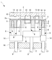
本実施形態に係るステープラ1は、サーキュラタイプの医療用ステープラであって、図1および図5に示されるように、円環状の先端面(把持面)2aを有する円筒状のステープルハウジング(ホルダ)2と、該ステープルハウジング2の中央孔2bと同一中心軸を貫通して軸線方向に配置されるセンターシャフト3と、該センターシャフト3の先端に着脱可能に取り付けられるセンターロッド4aを備えるアンビル4と、ステープルハウジング2を操作するハンドル(駆動部)15とを備えている。
本実施形態に係るステープラ1は、サーキュラタイプの医療用ステープラであって、図1および図5に示されるように、円環状の先端面(把持面)2aを有する円筒状のステープルハウジング(ホルダ)2と、該ステープルハウジング2の中央孔2bと同一中心軸を貫通して軸線方向に配置されるセンターシャフト3と、該センターシャフト3の先端に着脱可能に取り付けられるセンターロッド4aを備えるアンビル4と、ステープルハウジング2を操作するハンドル(駆動部)15とを備えている。
アンビル4のセンターロッド4aをセンターシャフト3に係合し、センターシャフト3を基端側に牽引することにより、アンビル4をステープルハウジング2の先端面2aに近接する閉状態となる位置に配置することができるようになっている。
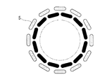
ステープルハウジング2には、多数のステープル5を、例えば、全周にわたって2列に周方向に配列して収容する円環状のステープルカセット(収容部)6と、該ステープルカセット6の径方向内方に全周にわたって配置された円環状のカッター7と、該ステープルカセット6に収容されたステープル5を先端面2aからアンビル4に向けて打ち出すプッシャ8と、該プッシャ8を押し出す駆動部材(駆動力伝達部)9とが備えられている。
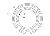
アンビル4には、図2に示されるように、ステープルハウジング2の各ステープル5の射出方向(軸方向)に対向する位置に配置された複数のアンビルポケット10を備えた円環状のアンビル部11と、該アンビル部11の径方向内方に、カッター7の刃先7aに軸方向に対向する位置に配置された受け部材12とが備えられている。カッター7にも駆動部材13が設けられており、カッター7を受け部材12に向けて押し出すことができるようになっている。
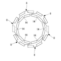
本実施形態に係るステープラ1においては、図4に示されるように、6個のプッシャ8が周方向に配列されることにより、全体として円環状に配列されている。各プッシャ8は、4個の押圧片14を備え、ステープルカセット6に収容されている内周側2個、外周側2個の合計4個のステープル5を、4個の押圧片14によって同時に打ち出すことができるようになっている。
また、図3A、図3Bおよび図4に示されるように、駆動部材9も各プッシャ8に1個ずつ接続されている。駆動部材9は、例えば、ワイヤであり、先端がプッシャ8に接続され、基端が駆動力を発生するハンドル15に接続されている。また、駆動部材9は、図3Aおよび図3Bに示されるように、プッシャ8との接続箇所近傍において、ステープルハウジング2に固定された支持部材16の貫通孔17を貫通することにより、ステープルハウジング2に対する移動方向がステープルハウジング2の長手軸に平行な方向のみに制限され、長手軸に交差する方向には移動しないように拘束されている。
ハンドル15は、操作者によって把持されて操作されるトリガー(図示略)を有している。トリガーは各駆動部材9に対応して駆動部材9と同数設けられていてもよいし、どの駆動部材9に駆動力を供給するかを選択するスイッチが設けられていてもよい。また、カッター7に接続する駆動部材13の基端にもトリガーが接続されている。
このように構成された本実施形態に係るステープラ1の作用について以下に説明する。
本実施形態に係るステープラ1を用いて組織(縫合対象物)Xを縫合および切断するには、まず、アンビル4を縫合する一方の管状組織(組織、縫合対象物)Xの中に挿入し、当該管状組織Xをアンビル4のセンターロッド4aに向けて包み込ませる。さらに、ステープルハウジング2を縫合する他方の管状組織Xの中に挿入し、当該管状組織Xをステープルハウジング2のセンターシャフト3に向けて包み込ませる。これにより、一方の管状組織Xは、アンビル4のアンビル部11および受け部材12を覆うように配置され、他方の管状組織Xはステープルハウジング2の先端面2aを覆うように配置される。
本実施形態に係るステープラ1を用いて組織(縫合対象物)Xを縫合および切断するには、まず、アンビル4を縫合する一方の管状組織(組織、縫合対象物)Xの中に挿入し、当該管状組織Xをアンビル4のセンターロッド4aに向けて包み込ませる。さらに、ステープルハウジング2を縫合する他方の管状組織Xの中に挿入し、当該管状組織Xをステープルハウジング2のセンターシャフト3に向けて包み込ませる。これにより、一方の管状組織Xは、アンビル4のアンビル部11および受け部材12を覆うように配置され、他方の管状組織Xはステープルハウジング2の先端面2aを覆うように配置される。
この状態で、アンビル4のセンターロッド4aをステープルハウジング2のセンターシャフト3に装着し、センターシャフト3を基端側に牽引することによって、アンビル4をステープルハウジング2に近接させて閉状態とする。これにより、ステープルハウジング2とアンビル4との間に組織Xを挟む。
そして、ハンドル15のトリガーを操作することにより、図3Bに示されるように、いずれかの駆動部材9を先端側に押し出して、該駆動部材9に接続されているプッシャ8を先端側に移動させ、ステープルカセット6内に収容されている4個のステープル5をプッシャ8の4個の押圧片14によって一度に打ち出して、ステープル5の針先によって組織Xを貫通させる。
そして、ハンドル15のトリガーを操作することにより、図3Bに示されるように、いずれかの駆動部材9を先端側に押し出して、該駆動部材9に接続されているプッシャ8を先端側に移動させ、ステープルカセット6内に収容されている4個のステープル5をプッシャ8の4個の押圧片14によって一度に打ち出して、ステープル5の針先によって組織Xを貫通させる。
組織Xを貫通したステープル5は、アンビル4に設けられたアンビルポケット10によって針先が折り返されるように湾曲変形させられることにより、その部分の組織Xを縫合することができる。操作者は、トリガーを順次操作していくことにより、プッシャ8を1つずつ先端側に移動させ、組織Xを縫合する。
この場合において、本実施形態によれば、全周にわたって配置されている全てのステープル5を同時に打ち出すのではなく、周方向に分離して配置された複数のプッシャ8を1つずつ押し出して周方向の一部のステープル5を押し出すので、トリガーを操作する際に操作者が加える力量を低減することができ、操作者にかかる負担を軽減することができるという利点がある。
また、この場合に、各プッシャ8に個別に駆動部材9が接続され、プッシャ8と駆動部材9との接続箇所近傍において、駆動部材9の移動方向が長手軸方向のみに制限されているので、プッシャ8にはステープル5の打ち出し方向に交差する方向への押圧力が作用せず、ズレが発生することを防止することができる。すなわち、ステープル5をアンビル4に向けて真っ直ぐに打ち出すことができ、安定した縫合を行うことができるという利点がある。
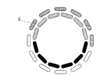
また、図3Aおよび図3Bに示されるように、周方向に配列された複数のプッシャ8を周方向一方向に沿って順に押し出すことにより、血流など組織Xが含む液体または気体を閉じ込めないように逃がしながら縫合することができるという利点がある。また、図6に(1)から(6)で示される数字に従って、径方向に対向する位置に配置された対となるプッシャ8を順に押し出すことにより、組織Xが伸びやすい組織であっても周方向に均等に縫合していくことができるという利点がある。
そして、全てのプッシャ8が押し出されて、組織Xの縫合が完了した後に、図示しないトリガーを操作して、カッター7を先端側に移動させる。これにより、ステープル5によって縫合された状態の組織Xの径方向内方において、カッター7の刃先7aのアンビル4の受け部材12との間に組織Xを挟み、かつ、受け部材12が破断する位置までカッター7が前進させられることによって、組織Xがカッター7によって円形に切断される。このような動作によって、組織Xの縫合と切離とが行われる。
なお、本実施形態においては、駆動部材9としてワイヤを例示したが、硬性のシャフトを採用してもよい。また、プッシャ8を周方向に6個配列した場合を例示したが、これに限定されるものではなく、プッシャ8の個数は2以上の任意の数でよい。
また、プッシャ8を周方向に複数備える場合について例示したが、これに代えて、図7に示されるようにグループ分けされたステープル5をグループ毎に打ち出すように、径方向に分離されたプッシャ8を採用してもよいし、図8に示されるようにグループ分けされたステープル5をグループ毎に打ち出すように、径方向および周方向の両方に分離されたプッシャ8を採用してもよい。
径方向に分離されたプッシャ8を採用する場合、径方向外側を縫合後に径方向内側を縫合することにより、血流など組織Xが含む液体または気体を閉じ込めないように切離面側に逃がしながら縫合することができるという利点がある。
また、径方向内側を縫合後に径方向外側を縫合することにより、出血を低減しながら縫合することができるという利点がある。
また、径方向内側を縫合後に径方向外側を縫合することにより、出血を低減しながら縫合することができるという利点がある。
また、本実施形態においては、ハンドル15に設けたトリガーに操作者がかけた力を駆動部材9によりプッシャ8に伝達して、手動でステープル5を打ち出すこととしたが、これに代えて、図9に示されるように、操作者によるハンドル15のトリガーの操作量に応じた駆動力を発生する動力源18を駆動部材9毎に設けることにしてもよい。
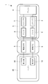
また、図10に示されるように、複数の動力源18を制御する動力源制御機構(制御部)19を設け、操作者によるボタン操作等の操作入力に応じて、いずれかのプッシャ8を選択して、対応する動力源18に動力を発生させることにしてもよい。
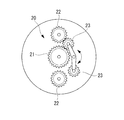
また、図11および図12に示されるように、単一の動力源18に対して複数の駆動部材9が対応づけられていて、選択されたプッシャ8に対応する駆動部材9と動力源18とが接続されるように切り替える駆動力伝達部制御機構20を備えていてもよい。図11に示す例では、動力源18であるモータに取り付けられた駆動ギヤ21と各駆動部材9に取り付けられた2つの従動ギヤ22との間にそれぞれ噛み合う2つの可動ギヤ23を設け、いずれかの可動ギヤ23が駆動ギヤ21と従動ギヤ22との間に噛み合うように切り替えることで、動力源18の駆動力をいずれかの駆動部材9のみに供給することができる。
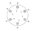
また、図13に示されるように、駆動部材9の長手方向の途中位置にクラッチ機構25を備えていてもよい。クラッチ機構25としては、各駆動部材9を個別に貫通させる貫通孔24を備えるとともに、各貫通孔24に、孔径を収縮させて駆動部材9を締め付けるものを採用すればよい。
このようにすることで、複数のプッシャ8を同時に移動させたい場合に、クラッチ機構25を作動させて、移動させたいプッシャ8に対応する駆動部材9を貫通させている貫通孔24を収縮させることにより、1つの駆動部材9に加える駆動力によって、複数(図13に示す例では駆動部材9と貫通孔24との間に斜線で示された2つ)の駆動部材9に接続された2つのプッシャ8を同時に押し出すことができる。
これにより、全てのプッシャ8を個別に押し出す場合の他、2以上のプッシャ8を同時に押し出すことが可能となり、ステープル5の打ち出しタイミングを調整することができる。
これにより、全てのプッシャ8を個別に押し出す場合の他、2以上のプッシャ8を同時に押し出すことが可能となり、ステープル5の打ち出しタイミングを調整することができる。
1 ステープラ
2 ステープルハウジング(ホルダ)
4 アンビル
5 ステープル
6 ステープルカセット(収容部)
8 プッシャ
9 駆動部材(駆動力伝達部)
15 ハンドル(駆動部)
18 動力源
19 動力源制御機構(制御部)
X 組織(縫合対象物)
2 ステープルハウジング(ホルダ)
4 アンビル
5 ステープル
6 ステープルカセット(収容部)
8 プッシャ
9 駆動部材(駆動力伝達部)
15 ハンドル(駆動部)
18 動力源
19 動力源制御機構(制御部)
X 組織(縫合対象物)
Claims (6)
- 縫合対象物を貫通する尖端を一方向に向けて複数のステープルを収容する収容部を備えるホルダと、
前記収容部に収容された前記ステープルを複数のグループ毎に押し出す複数のプッシャと、
該プッシャにより前記収容部から押し出された前記ステープルを押し付けて変形させるアンビルと、
各前記プッシャに別個に接続され、各接続箇所において各該前記プッシャによる押し出し方向以外の動きを拘束され、各前記プッシャを前記アンビルに向けて移動させる駆動力を伝達する駆動力伝達部と、
該駆動力伝達部により伝達される駆動力を発生する駆動部とを備えるステープラ。 - 各前記プッシャが、周方向に区分された複数のグループ毎に前記ステープルを押し出す請求項1に記載のステープラ。
- 各前記プッシャが、径方向に区分された複数のグループ毎に前記ステープルを押し出す請求項1または請求項2に記載のステープラ。
- 前記駆動部が、前記駆動力を手動により発生する請求項1から請求項3のいずれかに記載のステープラ。
- 前記駆動部が、前記駆動力を発生する動力源を備える請求項1から請求項3のいずれかに記載のステープラ。
- 前記駆動部が、所定のタイミングで各前記プッシャを移動させるよう前記駆動力伝達部により伝達される前記駆動力を制御する制御部を備える請求項1から請求項5のいずれかに記載のステープラ。
Priority Applications (3)
| Application Number | Priority Date | Filing Date | Title |
|---|---|---|---|
| PCT/JP2016/084074 WO2018092235A1 (ja) | 2016-11-17 | 2016-11-17 | ステープラ |
| JP2018550934A JPWO2018092235A1 (ja) | 2016-11-17 | 2016-11-17 | ステープラ |
| US16/297,821 US10980543B2 (en) | 2016-11-17 | 2019-03-11 | Stapler |
Applications Claiming Priority (1)
| Application Number | Priority Date | Filing Date | Title |
|---|---|---|---|
| PCT/JP2016/084074 WO2018092235A1 (ja) | 2016-11-17 | 2016-11-17 | ステープラ |
Related Child Applications (1)
| Application Number | Title | Priority Date | Filing Date |
|---|---|---|---|
| US16/297,821 Continuation US10980543B2 (en) | 2016-11-17 | 2019-03-11 | Stapler |
Publications (1)
| Publication Number | Publication Date |
|---|---|
| WO2018092235A1 true WO2018092235A1 (ja) | 2018-05-24 |
Family
ID=62145335
Family Applications (1)
| Application Number | Title | Priority Date | Filing Date |
|---|---|---|---|
| PCT/JP2016/084074 Ceased WO2018092235A1 (ja) | 2016-11-17 | 2016-11-17 | ステープラ |
Country Status (3)
| Country | Link |
|---|---|
| US (1) | US10980543B2 (ja) |
| JP (1) | JPWO2018092235A1 (ja) |
| WO (1) | WO2018092235A1 (ja) |
Families Citing this family (1)
| Publication number | Priority date | Publication date | Assignee | Title |
|---|---|---|---|---|
| US12059155B2 (en) | 2021-09-30 | 2024-08-13 | Cilag Gmbh International | Staple driver and guide assembly for circular surgical stapler |
Citations (3)
| Publication number | Priority date | Publication date | Assignee | Title |
|---|---|---|---|---|
| JPS5578950A (en) * | 1978-12-09 | 1980-06-14 | Takasago Ika Kogyo Kk | Suture device of duct portion in body |
| JP2010088882A (ja) * | 2008-10-10 | 2010-04-22 | Tyco Healthcare Group Lp | 旋回可能な顎部材を備えた外科用器具 |
| US20120016413A1 (en) * | 2010-07-14 | 2012-01-19 | Ethicon Endo-Surgery, Inc. | Surgical fastening devices comprising rivets |
Family Cites Families (16)
| Publication number | Priority date | Publication date | Assignee | Title |
|---|---|---|---|---|
| US4475679A (en) * | 1981-08-07 | 1984-10-09 | Fleury Jr George J | Multi-staple cartridge for surgical staplers |
| US4728020A (en) * | 1985-08-30 | 1988-03-01 | United States Surgical Corporation | Articulated surgical fastener applying apparatus |
| US4930503A (en) * | 1987-06-11 | 1990-06-05 | Pruitt J Crayton | Stapling process and device for use on the mesenteries of the abdomen |
| JPH0647050A (ja) | 1992-06-04 | 1994-02-22 | Olympus Optical Co Ltd | 組織縫合結紮器 |
| JP3926831B2 (ja) | 1992-06-04 | 2007-06-06 | オリンパス株式会社 | 組織縫合結紮器 |
| US5470008A (en) * | 1993-12-20 | 1995-11-28 | United States Surgical Corporation | Apparatus for applying surgical fasteners |
| US5833695A (en) * | 1994-07-13 | 1998-11-10 | Yoon; Inbae | Surgical stapling system and method of applying staples from multiple staple cartridges |
| US5655398A (en) * | 1995-05-11 | 1997-08-12 | Danieli United, A Division Of Danieli Corporation | Roll crossing and shifting system |
| US6601749B2 (en) | 1998-06-19 | 2003-08-05 | Scimed Life Systems, Inc. | Multi fire full thickness resectioning device |
| US6126058A (en) | 1998-06-19 | 2000-10-03 | Scimed Life Systems, Inc. | Method and device for full thickness resectioning of an organ |
| AU2003226050A1 (en) * | 2002-04-11 | 2003-10-27 | Tyco Healthcare Group, Lp | Surgical stapling apparatus including an anvil and cartridge each having cooperating mating surfaces |
| EP2015681B1 (en) * | 2006-05-03 | 2018-03-28 | Datascope Corp. | Tissue closure device |
| US8955732B2 (en) * | 2009-08-11 | 2015-02-17 | Covidien Lp | Surgical stapling apparatus |
| US8276801B2 (en) * | 2011-02-01 | 2012-10-02 | Tyco Healthcare Group Lp | Surgical stapling apparatus |
| US8453906B2 (en) | 2010-07-14 | 2013-06-04 | Ethicon Endo-Surgery, Inc. | Surgical instruments with electrodes |
| US9107663B2 (en) * | 2011-09-06 | 2015-08-18 | Ethicon Endo-Surgery, Inc. | Stapling instrument comprising resettable staple drivers |
-
2016
- 2016-11-17 JP JP2018550934A patent/JPWO2018092235A1/ja active Pending
- 2016-11-17 WO PCT/JP2016/084074 patent/WO2018092235A1/ja not_active Ceased
-
2019
- 2019-03-11 US US16/297,821 patent/US10980543B2/en active Active
Patent Citations (3)
| Publication number | Priority date | Publication date | Assignee | Title |
|---|---|---|---|---|
| JPS5578950A (en) * | 1978-12-09 | 1980-06-14 | Takasago Ika Kogyo Kk | Suture device of duct portion in body |
| JP2010088882A (ja) * | 2008-10-10 | 2010-04-22 | Tyco Healthcare Group Lp | 旋回可能な顎部材を備えた外科用器具 |
| US20120016413A1 (en) * | 2010-07-14 | 2012-01-19 | Ethicon Endo-Surgery, Inc. | Surgical fastening devices comprising rivets |
Also Published As
| Publication number | Publication date |
|---|---|
| JPWO2018092235A1 (ja) | 2019-10-10 |
| US10980543B2 (en) | 2021-04-20 |
| US20190200999A1 (en) | 2019-07-04 |
Similar Documents
| Publication | Publication Date | Title |
|---|---|---|
| US10702268B2 (en) | Staple feeding and forming apparatus | |
| CN109715084B (zh) | 医疗用机械手 | |
| CN101288594B (zh) | 一种手术缝合设备 | |
| EP0955904B1 (en) | Suturing system | |
| JP5456277B2 (ja) | ケーブル取り付け装置が改善されたケーブル駆動外科ステープル留め/切断器具 | |
| CA2531909C (en) | Surgical stapling device with tissue tensioner | |
| JP6258218B2 (ja) | ジョーが尚早に開くのを防止するための組織ステープラー安全スイッチ機構 | |
| US8136712B2 (en) | Surgical stapler with discrete staple height adjustment and tactile feedback | |
| JPWO2015146548A1 (ja) | 手術用器具 | |
| EP2286740A1 (en) | Surgical stapler | |
| WO2015137181A1 (ja) | 組織切除デバイス | |
| JP6821666B2 (ja) | 体内腔を径方向にまとめる器具及び方法 | |
| JP2008029831A (ja) | 手動式手術用切断固定器具 | |
| EP4048361B1 (en) | Agent delivery devices | |
| DK2142106T3 (en) | Device for dispensing staples of a shape memory alloy | |
| WO2018092235A1 (ja) | ステープラ | |
| CN119214705A (zh) | 一种纤维环缝合器 | |
| CN111345864B (zh) | 单电机电动手术器械 | |
| CN111345866B (zh) | 电动手术器械 | |
| CN111345863B (zh) | 电动手术器械 | |
| CN111345865B (zh) | 单电机电动手术器械 | |
| KR20230006150A (ko) | 원형 문합기 | |
| JP2008253629A (ja) | ステープルカートリッジ及び医療用ステープラ | |
| EP3130294A1 (en) | Disposable connecting unit of a circular stapler and a circular stapler | |
| KR20090051145A (ko) | 길다란 버트레스 스트립-디스펜싱 조립체, 길다란 버트레스 스트립-디스펜싱 카트리지, 수술용 버트레스-디스펜싱 장치, 및 수술용 버트레스 전달 조립체 |
Legal Events
| Date | Code | Title | Description |
|---|---|---|---|
| 121 | Ep: the epo has been informed by wipo that ep was designated in this application |
Ref document number: 16921575 Country of ref document: EP Kind code of ref document: A1 |
|
| ENP | Entry into the national phase |
Ref document number: 2018550934 Country of ref document: JP Kind code of ref document: A |
|
| NENP | Non-entry into the national phase |
Ref country code: DE |
|
| 122 | Ep: pct application non-entry in european phase |
Ref document number: 16921575 Country of ref document: EP Kind code of ref document: A1 |