WO2018083929A1 - 端末装置、基地局装置及び方法 - Google Patents
端末装置、基地局装置及び方法 Download PDFInfo
- Publication number
- WO2018083929A1 WO2018083929A1 PCT/JP2017/035940 JP2017035940W WO2018083929A1 WO 2018083929 A1 WO2018083929 A1 WO 2018083929A1 JP 2017035940 W JP2017035940 W JP 2017035940W WO 2018083929 A1 WO2018083929 A1 WO 2018083929A1
- Authority
- WO
- WIPO (PCT)
- Prior art keywords
- uplink
- measurement
- downlink
- satisfied
- condition
- Prior art date
Links
Images


Classifications
-
- H—ELECTRICITY
- H04—ELECTRIC COMMUNICATION TECHNIQUE
- H04L—TRANSMISSION OF DIGITAL INFORMATION, e.g. TELEGRAPHIC COMMUNICATION
- H04L5/00—Arrangements affording multiple use of the transmission path
- H04L5/003—Arrangements for allocating sub-channels of the transmission path
- H04L5/0048—Allocation of pilot signals, i.e. of signals known to the receiver
-
- H—ELECTRICITY
- H04—ELECTRIC COMMUNICATION TECHNIQUE
- H04W—WIRELESS COMMUNICATION NETWORKS
- H04W72/00—Local resource management
- H04W72/12—Wireless traffic scheduling
- H04W72/1263—Mapping of traffic onto schedule, e.g. scheduled allocation or multiplexing of flows
-
- H—ELECTRICITY
- H04—ELECTRIC COMMUNICATION TECHNIQUE
- H04W—WIRELESS COMMUNICATION NETWORKS
- H04W24/00—Supervisory, monitoring or testing arrangements
-
- H—ELECTRICITY
- H04—ELECTRIC COMMUNICATION TECHNIQUE
- H04W—WIRELESS COMMUNICATION NETWORKS
- H04W24/00—Supervisory, monitoring or testing arrangements
- H04W24/02—Arrangements for optimising operational condition
-
- H—ELECTRICITY
- H04—ELECTRIC COMMUNICATION TECHNIQUE
- H04W—WIRELESS COMMUNICATION NETWORKS
- H04W24/00—Supervisory, monitoring or testing arrangements
- H04W24/08—Testing, supervising or monitoring using real traffic
-
- H—ELECTRICITY
- H04—ELECTRIC COMMUNICATION TECHNIQUE
- H04W—WIRELESS COMMUNICATION NETWORKS
- H04W24/00—Supervisory, monitoring or testing arrangements
- H04W24/10—Scheduling measurement reports ; Arrangements for measurement reports
-
- H—ELECTRICITY
- H04—ELECTRIC COMMUNICATION TECHNIQUE
- H04W—WIRELESS COMMUNICATION NETWORKS
- H04W72/00—Local resource management
- H04W72/04—Wireless resource allocation
-
- H—ELECTRICITY
- H04—ELECTRIC COMMUNICATION TECHNIQUE
- H04W—WIRELESS COMMUNICATION NETWORKS
- H04W72/00—Local resource management
- H04W72/12—Wireless traffic scheduling
-
- H—ELECTRICITY
- H04—ELECTRIC COMMUNICATION TECHNIQUE
- H04W—WIRELESS COMMUNICATION NETWORKS
- H04W76/00—Connection management
- H04W76/20—Manipulation of established connections
- H04W76/28—Discontinuous transmission [DTX]; Discontinuous reception [DRX]
-
- H—ELECTRICITY
- H04—ELECTRIC COMMUNICATION TECHNIQUE
- H04W—WIRELESS COMMUNICATION NETWORKS
- H04W88/00—Devices specially adapted for wireless communication networks, e.g. terminals, base stations or access point devices
- H04W88/02—Terminal devices
-
- H—ELECTRICITY
- H04—ELECTRIC COMMUNICATION TECHNIQUE
- H04W—WIRELESS COMMUNICATION NETWORKS
- H04W92/00—Interfaces specially adapted for wireless communication networks
- H04W92/16—Interfaces between hierarchically similar devices
- H04W92/20—Interfaces between hierarchically similar devices between access points
-
- H—ELECTRICITY
- H04—ELECTRIC COMMUNICATION TECHNIQUE
- H04W—WIRELESS COMMUNICATION NETWORKS
- H04W72/00—Local resource management
- H04W72/04—Wireless resource allocation
- H04W72/044—Wireless resource allocation based on the type of the allocated resource
- H04W72/0453—Resources in frequency domain, e.g. a carrier in FDMA
-
- H—ELECTRICITY
- H04—ELECTRIC COMMUNICATION TECHNIQUE
- H04W—WIRELESS COMMUNICATION NETWORKS
- H04W88/00—Devices specially adapted for wireless communication networks, e.g. terminals, base stations or access point devices
- H04W88/08—Access point devices
Definitions
- the present disclosure relates to a terminal device, a base station device, and a method.
- LTE Long Term Evolution
- LTE-A Long Term Evolution
- LTE-A Pro Long Term Evolution Pro
- NR New Radio
- NRAT New Radio Access Technology
- EUTRA Evolved Universal Terrestrial Radio Access
- FEUTRA Further EUTRA
- LTE includes LTE-A, LTE-A Pro, and EUTRA
- NR includes NRAT and FEUTRA.
- LTE and NR a base station device (base station) is also called eNodeB (evolved NodeB), and a terminal device (mobile station, mobile station device, terminal) is also called UE (User Equipment).
- LTE and NR are cellular communication systems in which a plurality of areas covered by a base station apparatus are arranged in a cell shape. A single base station apparatus may manage a plurality of cells.
- NR is RAT (Radio Access Technology) different from LTE as a next-generation radio access method for LTE.
- NR is an access technology that can support various use cases including eMBB (Enhanced mobile broadband), mMTC (Massive machine type communications) and URLLC (Ultra reliable and low latency communications).
- eMBB Enhanced mobile broadband
- mMTC Massive machine type communications
- URLLC Ultra reliable and low latency communications
- Non-Patent Document 2 Details of a reference signal for measurement transmitted and received between a terminal device and a base station device for radio resource management are disclosed in Non-Patent Document 2.
- radio resources used for measurement for managing those radio resources are appropriately controlled according to the communication status.
- the present disclosure provides a mechanism that can improve the transmission efficiency of the entire system by appropriately using the measurement of the uplink reference signal for radio resource management.
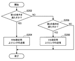
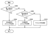
- a measurement unit that performs downlink measurement based on a downlink reference signal, and a transmission unit that transmits a first uplink reference signal based on a first setting related to measurement for radio resource management And the transmitter transmits the first uplink reference signal when the first condition is satisfied, and the measurement unit performs the downlink measurement when the second condition is satisfied.
- a terminal device is provided.
- the first uplink reference signal based on the transmitter configured to transmit the downlink reference signal and the first setting related to the measurement for radio resource management when the first condition is satisfied.
- the first uplink measurement is performed based on the first uplink reference signal transmitted by the terminal device that performs the downlink measurement based on the downlink reference signal.
- a base station apparatus including a measuring unit for performing.
- the second condition when the second condition is satisfied, downlink measurement is performed based on the downlink reference signal, and when the first condition is satisfied, measurement for managing radio resources is performed. Transmitting a first uplink reference signal based on a first setting is provided.
- the first uplink reference signal is transmitted based on the first setting related to the transmission for transmitting the downlink reference signal and the measurement for radio resource management when the first condition is satisfied. Transmitting and performing a first uplink measurement based on the first uplink reference signal transmitted by a terminal apparatus that performs a downlink measurement based on the downlink reference signal when the second condition is satisfied And a method executed by a processor including the same.
- elements having substantially the same functional configuration may be distinguished by adding different alphabets after the same reference numerals.
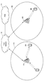
- a plurality of elements having substantially the same functional configuration are distinguished as required by the base station apparatuses 1A, 1B, and 1C.
- only the same reference numerals are given.
- the base station devices 1A, 1B, and 1C they are simply referred to as the base station device 1.
- the wireless communication system includes at least a base station device 1 and a terminal device 2.
- the base station device 1 can accommodate a plurality of terminal devices.
- the base station device 1 can be connected to other base station devices by means of an X2 interface.
- the base station apparatus 1 can be connected to an EPC (Evolved Packet Core) by means of an S1 interface.
- the base station apparatus 1 can be connected to an MME (Mobility Management Entity) by means of an S1-MME interface, and can be connected to an S-GW (Serving Gateway) by means of an S1-U interface.
- the S1 interface supports a many-to-many connection between the MME and / or S-GW and the base station apparatus 1.
- the base station apparatus 1 and the terminal device 2 support LTE and / or NR, respectively.
- each of the base station device 1 and the terminal device 2 supports one or more radio access technologies (RAT).
- RAT includes LTE and NR.
- One RAT corresponds to one cell (component carrier). That is, when multiple RATs are supported, each RAT corresponds to a different cell.
- a cell is a combination of downlink resources, uplink resources, and / or side links.
- LTE Long Term Evolution
- NR New Radio Access
- Downlink communication is communication from the base station device 1 to the terminal device 2.
- the downlink transmission is transmission from the base station apparatus 1 to the terminal apparatus 2 and is transmission of a downlink physical channel and / or a downlink physical signal.
- Uplink communication is communication from the terminal device 2 to the base station device 1.
- Uplink transmission is transmission from the terminal apparatus 2 to the base station apparatus 1 and is transmission of an uplink physical channel and / or an uplink physical signal.
- the side link communication is communication from the terminal device 2 to another terminal device 2.
- the side link transmission is transmission from the terminal device 2 to another terminal device 2 and is transmission of a side link physical channel and / or a side link physical signal.
- Side link communication is defined for proximity direct detection and proximity direct communication between terminal devices.
- the side link communication can use the same frame configuration as the uplink and downlink. Further, side link communication may be limited to a part (subset) of uplink resources and / or downlink resources.
- the base station apparatus 1 and the terminal apparatus 2 can support communication using a set of one or more cells in the downlink, uplink, and / or side link. Communication by a set of a plurality of cells or a set of a plurality of cells is also referred to as carrier aggregation or dual connectivity. Details of carrier aggregation and dual connectivity will be described later.
- Each cell uses a predetermined frequency bandwidth. A maximum value, a minimum value, and a settable value in a predetermined frequency bandwidth can be defined in advance.
- FIG. 1 is a diagram showing an example of component carrier settings in the present embodiment.
- one LTE cell and two NR cells are set.
- One LTE cell is set as a primary cell.
- the two NR cells are set as a primary secondary cell and a secondary cell, respectively.
- the two NR cells are integrated by carrier aggregation.
- the LTE cell and the NR cell are integrated by dual connectivity. Note that the LTE cell and the NR cell may be integrated by carrier aggregation.
- the NR since the NR can be assisted by the LTE cell that is the primary cell, the NR may not support some functions such as a function for performing stand-alone communication.
- the function for stand-alone communication includes a function necessary for initial connection.
- FIG. 2 is a diagram illustrating an example of component carrier settings in the present embodiment.
- two NR cells are set.
- the two NR cells are set as a primary cell and a secondary cell, respectively, and are integrated by carrier aggregation.
- the support of the LTE cell becomes unnecessary by supporting the function for the NR cell to perform stand-alone communication.
- the two NR cells may be integrated by dual connectivity.
- a radio frame composed of 10 ms (milliseconds) is defined.
- Each radio frame is composed of two half frames.
- the time interval of the half frame is 5 ms.
- Each half frame is composed of five subframes.
- the subframe time interval is 1 ms and is defined by two consecutive slots.
- the slot time interval is 0.5 ms.
- the i-th subframe in the radio frame is composed of a (2 ⁇ i) th slot and a (2 ⁇ i + 1) th slot. That is, 10 subframes are defined in each radio frame.
- the subframe includes a downlink subframe, an uplink subframe, a special subframe, a sidelink subframe, and the like.
- the downlink subframe is a subframe reserved for downlink transmission.
- An uplink subframe is a subframe reserved for uplink transmission.
- the special subframe is composed of three fields. The three fields include DwPTS (Downlink Pilot Time Slot), GP (Guard Period), and UpPTS (Uplink Pilot Time Slot). The total length of DwPTS, GP, and UpPTS is 1 ms.
- DwPTS is a field reserved for downlink transmission.
- UpPTS is a field reserved for uplink transmission.
- GP is a field in which downlink transmission and uplink transmission are not performed. Note that the special subframe may be configured only by DwPTS and GP, or may be configured only by GP and UpPTS.
- the special subframe is arranged between the downlink subframe and the uplink subframe in TDD (Time Division Duplex), and is used for switching from the downlink subframe to the uplink subframe.
- the side link subframe is a subframe reserved or set for side link communication.
- the side link is used for proximity direct communication and proximity direct detection between terminal devices.
- a single radio frame includes a downlink subframe, an uplink subframe, a special subframe, and / or a sidelink subframe. Also, a single radio frame may be composed of only downlink subframes, uplink subframes, special subframes, or sidelink subframes.
- the radio frame configuration is defined by the frame configuration type.
- Frame configuration type 1 is applicable only to FDD (Frequency Division Duplex).
- Frame configuration type 2 is applicable only to TDD.
- Frame configuration type 3 is applicable only to operation of LAA (Licensed Assisted Access) secondary cells.
- each of the 10 subframes in one radio frame corresponds to one of a downlink subframe, an uplink subframe, and a special subframe.
- Subframe 0, subframe 5 and DwPTS are always reserved for downlink transmission.
- the subframe immediately following UpPTS and its special subframe is always reserved for uplink transmission.
- the terminal device 2 can handle a subframe in which no PDSCH or detection signal is transmitted as an empty subframe.
- the terminal apparatus 2 assumes that no signal and / or channel exists in the subframe unless a predetermined signal, channel and / or downlink transmission is detected in the subframe.
- Downlink transmission is dedicated in one or more consecutive subframes.
- the first subframe of the downlink transmission may start from anywhere within that subframe.
- the last subframe of the downlink transmission may be either completely occupied or dedicated at a time interval defined by DwPTS.
- 10 subframes in one radio frame may be reserved for uplink transmission. Further, each of the 10 subframes in one radio frame may correspond to any of a downlink subframe, an uplink subframe, a special subframe, and a sidelink subframe.
- the base station apparatus 1 may transmit the downlink physical channel and the downlink physical signal in DwPTS of the special subframe.
- the base station apparatus 1 can restrict PBCH transmission in DwPTS of the special subframe.
- the terminal device 2 may transmit an uplink physical channel and an uplink physical signal in the UpPTS of the special subframe.
- the terminal device 2 can restrict transmission of some uplink physical channels and uplink physical signals in the UpPTS of the special subframe.
- TTI Transmission Time Interval
- 1 ms (1 subframe) 1 TTI.
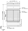
- FIG. 3 is a diagram illustrating an example of an LTE downlink subframe in the present embodiment.
- the diagram shown in FIG. 3 is also referred to as an LTE downlink resource grid.
- the base station apparatus 1 can transmit an LTE downlink physical channel and / or an LTE downlink physical signal in a downlink subframe to the terminal apparatus 2.
- the terminal apparatus 2 can receive an LTE downlink physical channel and / or an LTE downlink physical signal in the downlink subframe from the base station apparatus 1.
- FIG. 4 is a diagram illustrating an example of an LTE uplink subframe in the present embodiment.
- the diagram shown in FIG. 4 is also referred to as an LTE uplink resource grid.
- the terminal device 2 can transmit an LTE uplink physical channel and / or an LTE uplink physical signal in an uplink subframe to the base station device 1.
- the base station apparatus 1 can receive an LTE uplink physical channel and / or an LTE uplink physical signal in an uplink subframe from the terminal apparatus 2.
- LTE physical resources can be defined as follows.
- One slot is defined by a plurality of symbols.
- the physical signal or physical channel transmitted in each of the slots is represented by a resource grid.
- the resource grid is defined by a plurality of subcarriers in the frequency direction and a plurality of OFDM symbols in the time direction.
- the resource grid is defined by a plurality of subcarriers in the frequency direction and a plurality of SC-FDMA symbols in the time direction.
- the number of subcarriers or resource blocks may be determined depending on the cell bandwidth.
- the number of symbols in one slot is determined by the CP (Cyclic Prefix) type.
- the CP type is a normal CP or an extended CP.
- the number of OFDM symbols or SC-FDMA symbols constituting one slot is seven.
- the number of OFDM symbols or SC-FDMA symbols constituting one slot is six.
- Each element in the resource grid is called a resource element.
- the resource element is identified using a subcarrier index (number) and a symbol index (number).
- the OFDM symbol or SC-FDMA symbol is also simply referred to as a symbol.
- the resource block is used for mapping a certain physical channel (such as PDSCH or PUSCH) to a resource element.
- the resource block includes a virtual resource block and a physical resource block.
- a certain physical channel is mapped to a virtual resource block.
- a virtual resource block is mapped to a physical resource block.
- One physical resource block is defined by a predetermined number of consecutive symbols in the time domain.
- One physical resource block is defined from a predetermined number of consecutive subcarriers in the frequency domain. The number of symbols and the number of subcarriers in one physical resource block are determined based on the type of CP in the cell, the subcarrier spacing, and / or parameters set by higher layers.
- one physical resource block is composed of (7 ⁇ 12) resource elements. Physical resource blocks are numbered from 0 in the frequency domain. Further, two resource blocks in one subframe corresponding to the same physical resource block number are defined as physical resource block pairs (PRB pair, RB pair).
- the predetermined parameter is a parameter (physical parameter) related to the transmission signal.
- Parameters related to the transmission signal include CP length, subcarrier interval, number of symbols in one subframe (predetermined time length), number of subcarriers in one resource block (predetermined frequency band), multiple access scheme, and signal Includes waveforms.
- the downlink signal and the uplink signal are generated using one predetermined parameter in each predetermined time length (for example, subframe).
- the terminal apparatus 2 generates a downlink signal transmitted from the base station apparatus 1 and an uplink signal transmitted to the base station apparatus 1 with one predetermined parameter for each predetermined time length.
- the base station apparatus 1 generates a downlink signal transmitted to the terminal apparatus 2 and an uplink signal transmitted from the terminal apparatus 2 with one predetermined parameter for each predetermined time length.
- ⁇ Frame structure of NR in this embodiment> In each of the NR cells, one or more predetermined parameters are used in a certain predetermined time length (for example, subframe). That is, in the NR cell, the downlink signal and the uplink signal are each generated with one or more predetermined parameters in a predetermined time length.
- the terminal apparatus 2 generates a downlink signal transmitted from the base station apparatus 1 and an uplink signal transmitted to the base station apparatus 1 with one or more predetermined parameters in a predetermined time length.
- the base station apparatus 1 generates a downlink signal to be transmitted to the terminal apparatus 2 and an uplink signal to be transmitted from the terminal apparatus 2 with one or more predetermined parameters for each predetermined time length.
- the predetermined method includes FDM (Frequency Division Multiplexing), TDM (Time Division Multiplexing), CDM (Code Division Multiplexing), and / or SDM (Spatial Division Multiplexing).
- FDM Frequency Division Multiplexing
- TDM Time Division Multiplexing
- CDM Code Division Multiplexing
- SDM Spatial Division Multiplexing
- a plurality of types of combinations of predetermined parameters set in the NR cell can be specified in advance as a parameter set.
- FIG. 5 is a diagram illustrating an example of a parameter set relating to a transmission signal in the NR cell.
- the parameters related to the transmission signal included in the parameter set are the subcarrier interval, the number of subcarriers per resource block in the NR cell, the number of symbols per subframe, and the CP length type.
- the CP length type is a CP length type used in the NR cell.
- CP length type 1 corresponds to a normal CP in LTE
- CP length type 2 corresponds to an extended CP in LTE.
- Parameter sets related to transmission signals in the NR cell can be individually defined for the downlink and uplink. Also, parameter sets related to transmission signals in the NR cell can be set independently for the downlink and uplink.
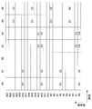
- FIG. 6 is a diagram illustrating an example of an NR downlink subframe in the present embodiment.
- a signal generated using the parameter set 1, the parameter set 0, and the parameter set 2 is FDM in the cell (system bandwidth).
- the diagram shown in FIG. 6 is also referred to as the NR downlink resource grid.
- the base station apparatus 1 can transmit an NR downlink physical channel and / or an NR downlink physical signal in a downlink subframe to the terminal apparatus 2.
- the terminal apparatus 2 can receive the NR downlink physical channel and / or the NR downlink physical signal in the downlink subframe from the base station apparatus 1.
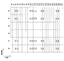
- FIG. 7 is a diagram illustrating an example of an uplink subframe of NR in the present embodiment.
- a signal generated using parameter set 1, parameter set 0, and parameter set 2 is FDM in a cell (system bandwidth).
- the diagram shown in FIG. 6 is also referred to as the NR uplink resource grid.
- the base station apparatus 1 can transmit an NR uplink physical channel and / or an NR uplink physical signal in an uplink subframe to the terminal apparatus 2.
- the terminal apparatus 2 can receive the NR uplink physical channel and / or the NR uplink physical signal in the uplink subframe from the base station apparatus 1.
- An antenna port is defined so that a propagation channel carrying one symbol can be inferred from a propagation channel carrying another symbol at the same antenna port. For example, it can be assumed that different physical resources in the same antenna port are transmitted on the same propagation channel. In other words, a symbol at a certain antenna port can be demodulated by estimating a propagation channel using a reference signal at that antenna port. There is one resource grid per antenna port.
- An antenna port is defined by a reference signal. Each reference signal can define a plurality of antenna ports.
- antenna port 0 to 3 are antenna ports to which CRS is transmitted. That is, the PDSCH transmitted through the antenna ports 0 to 3 can be demodulated by the CRS corresponding to the antenna ports 0 to 3.
- the two antenna ports satisfy a predetermined condition, they can be expressed as quasi-identical positions (QCL: Quasi co-location).
- the predetermined condition is that the wide-area characteristics of a propagation channel carrying a symbol at one antenna port can be inferred from the propagation channel carrying a symbol at another antenna port.
- Global characteristics include delay dispersion, Doppler spread, Doppler shift, average gain and / or average delay.
- the antenna port number may be defined differently for each RAT, or may be defined in common between RATs.
- antenna ports 0 to 3 in LTE are antenna ports through which CRS is transmitted.
- the antenna ports 0 to 3 can be antenna ports through which CRS similar to LTE is transmitted.
- an antenna port for transmitting a CRS similar to LTE can have an antenna port number different from antenna ports 0 to 3.
- the predetermined antenna port number can be applied to LTE and / or NR.
- the physical channel includes a downlink physical channel, an uplink physical channel, and a side link physical channel.
- the physical signal includes a downlink physical signal, an uplink physical signal, and a side link physical signal.
- the physical channel and physical signal in LTE are also referred to as LTE physical channel and LTE physical signal, respectively.
- the physical channel and physical signal in NR are also referred to as NR physical channel and NR physical signal, respectively.
- the LTE physical channel and the NR physical channel can be defined as different physical channels.
- the LTE physical signal and the NR physical signal can be defined as different physical signals.
- the LTE physical channel and the NR physical channel are also simply referred to as physical channels, and the LTE physical signal and the NR physical signal are also simply referred to as physical signals. That is, the description for the physical channel can be applied to both the LTE physical channel and the NR physical channel.
- the description for the physical signal can be applied to both the LTE physical signal and the NR physical signal.
- NR physical channel and NR physical signal in this embodiment The description for the physical channel and the physical signal in LTE can be applied to the NR physical channel and the NR physical signal, respectively.
- the NR physical channel and the NR physical signal are referred to as follows.
- NR downlink physical channels include NR-PBCH, NR-PCFICH, NR-PHICH, NR-PDCCH, NR-EPDCCH, NR-MPDCCH, NR-R-PDCCH, NR-PDSCH, NR-PMCH, and the like.
- NR downlink physical signals include NR-SS, NR-DL-RS, NR-DS, and the like.
- NR-SS includes NR-PSS, NR-SSS, and the like.
- the NR-RS includes NR-CRS, NR-PDSCH-DMRS, NR-EPDCCH-DMRS, NR-PRS, NR-CSI-RS, NR-TRS, and the like.
- NR uplink physical channel includes NR-PUSCH, NR-PUCCH, NR-PRACH, and the like.
- NR uplink physical signal includes NR-UL-RS.
- NR-UL-RS includes NR-UL-DMRS and NR-SRS.
- NR side link physical channels include NR-PSBCH, NR-PSCCH, NR-PSDCH, NR-PSSCH, and the like.
- the synchronization signal is used for the terminal apparatus 2 to synchronize the downlink frequency domain and / or time domain.
- the synchronization signal includes PSS (Primary Synchronization Signal) and SSS (Secondary Synchronization Signal).
- the synchronization signal is arranged in a predetermined subframe in the radio frame. For example, in the TDD scheme, the synchronization signal is arranged in subframes 0, 1, 5, and 6 in the radio frame. In the FDD scheme, the synchronization signal is arranged in subframes 0 and 5 in the radio frame.
- PSS may be used for coarse frame / symbol timing synchronization (time domain synchronization) and cell identification group identification.
- the SSS may be used for more accurate frame timing synchronization, cell identification, and CP length detection. That is, frame timing synchronization and cell identification can be performed by using PSS and SSS.
- the terminal apparatus 2 estimates downlink physical channel propagation path, propagation path correction, downlink CSI (Channel State Information) calculation, and / or positioning measurement of the terminal apparatus 2. Used to do
- CRS is transmitted in the entire bandwidth of the subframe.
- CRS is used to receive (demodulate) PBCH, PDCCH, PHICH, PCFICH, and PDSCH.
- the CRS may be used for the terminal device 2 to calculate downlink channel state information.
- PBCH, PDCCH, PHICH, and PCFICH are transmitted by an antenna port used for transmission of CRS.
- CRS supports 1, 2 or 4 antenna port configurations.
- CRS is transmitted on one or more of antenna ports 0-3.
- URS related to PDSCH is transmitted in a subframe and a band used for transmission of PDSCH related to URS. URS is used to demodulate the PDSCH with which the URS is associated. The URS associated with the PDSCH is transmitted on one or more of the antenna ports 5, 7-14.
- the PDSCH is transmitted by an antenna port used for transmission of CRS or URS based on the transmission mode and the DCI format.
- the DCI format 1A is used for scheduling of PDSCH transmitted through an antenna port used for CRS transmission.
- the DCI format 2D is used for scheduling of the PDSCH transmitted through the antenna port used for URS transmission.
- DMRS related to EPDCCH is transmitted in subframes and bands used for transmission of EPDCCH related to DMRS.
- DMRS is used to demodulate the EPDCCH with which DMRS is associated.
- the EPDCCH is transmitted through an antenna port used for DMRS transmission.
- the DMRS associated with the EPDCCH is transmitted on one or more of the antenna ports 107-114.
- CSI-RS is transmitted in the set subframe. Resources for transmitting the CSI-RS are set by the base station apparatus 1.
- the CSI-RS is used for the terminal apparatus 2 to calculate downlink channel state information.
- the terminal device 2 performs signal measurement (channel measurement) using CSI-RS.
- CSI-RS supports configuration of some or all antenna ports of 1, 2, 4, 8, 12, 16, 24 and 32.
- CSI-RS is transmitted on one or more of antenna ports 15-46.
- the supported antenna port may be determined based on the terminal device capability of the terminal device 2, the setting of the RRC parameter, and / or the set transmission mode.
- ZP CSI-RS resources are set by higher layers. ZP CSI-RS resources may be transmitted with zero output power. That is, no ZP CSI-RS resource need be transmitted. PDSCH and EPDCCH are not transmitted in the resource set by ZP CSI-RS.
- ZP CSI-RS resources are used by neighboring cells to transmit NZP CSI-RS.
- ZP CSI-RS resources are used to measure CSI-IM.
- the ZP CSI-RS resource is a resource to which a predetermined channel such as PDSCH is not transmitted. In other words, a predetermined channel is mapped by excluding ZP CSI-RS resources (rate matching and puncturing).
- the PUCCH is a physical channel used for transmitting uplink control information (UPCI).
- the uplink control information includes downlink channel state information (CSI), scheduling request (SR) indicating a request for PUSCH resources, downlink data (Transport block: TB, Downlink-Shared Channel: DL).
- -SCH downlink data for HARQ-ACK.
- HARQ-ACK is also referred to as ACK / NACK, HARQ feedback, or response information.
- HARQ-ACK for downlink data indicates ACK, NACK, or DTX.
- PUSCH is a physical channel used for transmitting uplink data (Uplink-Shared Channel: UL-SCH).
- the PUSCH may also be used to transmit HARQ-ACK and / or channel state information along with uplink data. Also, the PUSCH may be used to transmit only channel state information or only HARQ-ACK and channel state information.
- PRACH is a physical channel used to transmit a random access preamble.
- the PRACH can be used for the terminal device 2 to synchronize with the base station device 1 in the time domain.
- PRACH is an initial connection establishment procedure (processing), a handover procedure, a connection re-establishment procedure, synchronization for uplink transmission (timing adjustment), and / or PUSCH resource request. Also used to indicate
- a plurality of PUCCHs are frequency, time, space and / or code multiplexed.
- a plurality of PUSCHs may be frequency, time, space and / or code multiplexed.
- PUCCH and PUSCH may be frequency, time, space and / or code multiplexed.
- the PRACH may be arranged over a single subframe or two subframes. A plurality of PRACHs may be code-multiplexed.
- UL-DMRS is related to transmission of PUSCH or PUCCH.
- UL-DMRS is time-multiplexed with PUSCH or PUCCH.
- the base station apparatus 1 may use UL-DMRS to perform PUSCH or PUCCH propagation path correction.
- PUSCH transmission also includes multiplexing and transmitting PUSCH and UL-DMRS.
- the transmission of PUCCH includes multiplexing and transmitting PUCCH and UL-DMRS.
- SRS is not related to PUSCH or PUCCH transmission.
- the base station apparatus 1 may use SRS in order to measure the uplink channel state.
- SRS is transmitted using the last symbol in the uplink subframe. That is, the SRS is arranged in the last symbol in the uplink subframe.
- the terminal device 2 can restrict simultaneous transmission of SRS and PUCCH, PUSCH and / or PRACH in a certain symbol of a certain cell.
- the terminal apparatus 2 transmits PUSCH and / or PUCCH using a symbol excluding the last symbol in the uplink subframe in an uplink subframe of a certain cell, and the last symbol in the uplink subframe. Can be used to transmit SRS. That is, in a certain uplink subframe of a certain cell, the terminal device 2 can transmit SRS, PUSCH and PUCCH.
- trigger type 0 SRS and trigger type 1 SRS are defined as SRSs having different trigger types.
- the trigger type 0 SRS is transmitted when parameters related to the trigger type 0 SRS are set by higher layer signaling.
- the trigger type 1 SRS is transmitted when a parameter related to the trigger type 1 SRS is set by higher layer signaling and transmission is requested by an SRS request included in the DCI format 0, 1A, 2B, 2C, 2D, or 4.
- the SRS request is included in both FDD and TDD for DCI formats 0, 1A, and 4, and is included only in TDD for DCI formats 2B, 2C, and 2D.
- Trigger type 0 SRS is also referred to as periodic SRS.
- Trigger type 1 SRS is also referred to as aperiodic SRS.
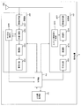
- FIG. 8 is a schematic block diagram illustrating the configuration of the base station device 1 of the present embodiment.
- the base station apparatus 1 includes an upper layer processing unit 101, a control unit 103, a receiving unit 105, a transmitting unit 107, and a transmission / reception antenna 109.
- the reception unit 105 includes a decoding unit 1051, a demodulation unit 1053, a demultiplexing unit 1055, a radio reception unit 1057, and a channel measurement unit 1059.
- the transmission unit 107 includes an encoding unit 1071, a modulation unit 1073, a multiplexing unit 1075, a radio transmission unit 1077, and a downlink reference signal generation unit 1079.
- the base station apparatus 1 can support one or more RATs.
- Part or all of the units included in the base station apparatus 1 shown in FIG. 8 can be individually configured according to the RAT.
- the reception unit 105 and the transmission unit 107 are individually configured with LTE and NR.
- a part or all of each unit included in the base station apparatus 1 shown in FIG. 8 can be individually configured according to a parameter set related to a transmission signal.
- the radio reception unit 1057 and the radio transmission unit 1077 can be individually configured according to a parameter set related to a transmission signal.
- the upper layer processing unit 101 includes a medium access control (MAC) layer, a packet data integration protocol (Packet Data Convergence Protocol: PDCP) layer, a radio link control (Radio Link Control: RLC) layer, a radio resource control (Radio). Process Resource Control: RRC) layer. Further, the upper layer processing unit 101 generates control information for controlling the reception unit 105 and the transmission unit 107 and outputs the control information to the control unit 103.
- MAC medium access control
- PDCP Packet Data Convergence Protocol
- RLC Radio Link Control
- Radio Radio
- RRC Radio Resource Control
- the control unit 103 controls the reception unit 105 and the transmission unit 107 based on the control information from the higher layer processing unit 101.
- the control unit 103 generates control information for the upper layer processing unit 101 and outputs the control information to the upper layer processing unit 101.
- the control unit 103 inputs the decoded signal from the decoding unit 1051 and the channel estimation result from the channel measurement unit 1059.
- the control unit 103 outputs a signal to be encoded to the encoding unit 1071.
- the control unit 103 is used to control all or part of the base station apparatus 1.
- the upper layer processing unit 101 performs processing and management related to RAT control, radio resource control, subframe setting, scheduling control, and / or CSI report control.
- the processing and management in the upper layer processing unit 101 is performed for each terminal device or for the terminal devices connected to the base station device.
- the processing and management in the upper layer processing unit 101 may be performed only by the upper layer processing unit 101, or may be acquired from an upper node or another base station device. Further, the processing and management in the upper layer processing unit 101 may be performed individually according to the RAT. For example, the upper layer processing unit 101 individually performs processing and management in LTE and processing and management in NR.
- management related to RAT is performed.
- management related to LTE and / or management related to NR is performed.
- Management regarding NR includes setting and processing of parameter sets regarding transmission signals in the NR cell.
- radio resource control in the upper layer processing unit 101, generation and / or management of downlink data (transport block), system information, RRC message (RRC parameter), and / or MAC control element (CE) is performed. Done.
- subframe setting in the upper layer processing unit 101 subframe setting, subframe pattern setting, uplink-downlink setting, uplink reference UL-DL setting, and / or downlink reference UL-DL setting are managed. Is called.
- the subframe setting in higher layer processing section 101 is also referred to as base station subframe setting.
- the subframe setting in the higher layer processing unit 101 can be determined based on the uplink traffic volume and the downlink traffic volume. Further, the subframe setting in the upper layer processing unit 101 can be determined based on the scheduling result of the scheduling control in the upper layer processing unit 101.
- the frequency and subframe to which a physical channel is allocated, the physical channel's A coding rate, a modulation scheme, transmission power, and the like are determined.
- the control unit 103 generates control information (DCI format) based on the scheduling result of scheduling control in the upper layer processing unit 101.
- the CSI report of the terminal device 2 is controlled.
- the setting related to the CSI reference resource to be assumed for calculating the CSI in the terminal device 2 is controlled.
- the receiving unit 105 receives a signal transmitted from the terminal device 2 via the transmission / reception antenna 109 in accordance with control from the control unit 103, further performs reception processing such as separation, demodulation, and decoding, and receives the received information. Output to the control unit 103. Note that the reception process in the reception unit 105 is performed based on a setting specified in advance or a setting notified from the base station apparatus 1 to the terminal apparatus 2.
- the radio reception unit 1057 converts the uplink signal received via the transmission / reception antenna 109 into an intermediate frequency (down-conversion), removes unnecessary frequency components, and appropriately maintains the signal level. Control of amplification level, quadrature demodulation based on in-phase and quadrature components of received signal, conversion from analog signal to digital signal, removal of guard interval (GI), and / or fast Fourier transform (Fast Fourier transform) Extract frequency domain signals by Transform: FFT).
- GI guard interval
- FFT fast Fourier transform
- the demultiplexing unit 1055 separates an uplink channel such as PUCCH or PUSCH and / or an uplink reference signal from the signal input from the radio reception unit 1057.
- the demultiplexing unit 1055 outputs the uplink reference signal to the channel measurement unit 1059.
- the demultiplexing unit 1055 performs channel compensation for the uplink channel from the channel estimation value input from the channel measurement unit 1059.
- the demodulation unit 1053 receives a received signal using a modulation scheme such as BPSK (Binary Phase Shift Keying), QPSK (Quadrature Phase Shift Keying), 16QAM (Quadrature Amplitude Modulation), 64QAM, or 256QAM for the modulation symbol of the uplink channel. Is demodulated.
- Demodulation section 1053 separates and demodulates the MIMO multiplexed uplink channel.
- the decoding unit 1051 performs a decoding process on the demodulated uplink channel encoded bits.
- the decoded uplink data and / or uplink control information is output to the control unit 103.
- Decoding section 1051 performs decoding processing for each transport block for PUSCH.
- the channel measurement unit 1059 measures the propagation path estimation value and / or channel quality from the uplink reference signal input from the demultiplexing unit 1055, and outputs it to the demultiplexing unit 1055 and / or the control unit 103.
- the channel measurement unit 1059 measures a channel estimation value for channel compensation for PUCCH or PUSCH using UL-DMRS, and measures the channel quality in the uplink using SRS.
- the transmission unit 107 performs transmission processing such as encoding, modulation, and multiplexing on the downlink control information and the downlink data input from the higher layer processing unit 101 according to the control from the control unit 103. For example, the transmission unit 107 generates and multiplexes PHICH, PDCCH, EPDCCH, PDSCH, and a downlink reference signal, and generates a transmission signal. Note that the transmission processing in the transmission unit 107 is based on settings specified in advance, settings notified from the base station apparatus 1 to the terminal apparatus 2, or settings notified via the PDCCH or EPDCCH transmitted in the same subframe. Done.
- the encoding unit 1071 performs HARQ indicator (HARQ-ACK), downlink control information, and downlink data input from the control unit 103 with predetermined encoding such as block encoding, convolutional encoding, and turbo encoding. Encoding is performed using a method.
- the modulation unit 1073 modulates the coded bits input from the coding unit 1071 with a predetermined modulation method such as BPSK, QPSK, 16QAM, 64QAM, 256QAM.
- the downlink reference signal generation unit 1079 generates a downlink reference signal based on a physical cell identifier (PCI), an RRC parameter set in the terminal device 2, and the like.
- Multiplexer 1075 multiplexes the modulation symbols and downlink reference signals for each channel and arranges them in a predetermined resource element.
- the radio transmission unit 1077 converts the signal from the multiplexing unit 1075 into a time-domain signal by inverse fast Fourier transform (IFFT), adds a guard interval, generates a baseband digital signal, Performs conversion to analog signal, quadrature modulation, conversion from intermediate frequency signal to high frequency signal (up-convert), removal of excess frequency components, power amplification, etc. to generate a transmission signal .
- IFFT inverse fast Fourier transform
- the transmission signal output from the wireless transmission unit 1077 is transmitted from the transmission / reception antenna 109.
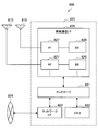
- FIG. 9 is a schematic block diagram showing the configuration of the terminal device 2 of the present embodiment.
- the terminal device 2 includes an upper layer processing unit 201, a control unit 203, a reception unit 205, a transmission unit 207, and a transmission / reception antenna 209.
- the reception unit 205 includes a decoding unit 2051, a demodulation unit 2053, a demultiplexing unit 2055, a radio reception unit 2057, and a channel measurement unit 2059.
- the transmission unit 207 includes an encoding unit 2071, a modulation unit 2073, a multiplexing unit 2075, a radio transmission unit 2077, and an uplink reference signal generation unit 2079.
- the terminal device 2 can support one or more RATs. Some or all of the units included in the terminal device 2 illustrated in FIG. 9 can be individually configured according to the RAT.
- the reception unit 205 and the transmission unit 207 are individually configured with LTE and NR.
- the NR cell some or all of the units included in the terminal device 2 shown in FIG. 9 can be individually configured according to the parameter set related to the transmission signal.
- the radio reception unit 2057 and the radio transmission unit 2077 can be individually configured according to a parameter set related to a transmission signal.
- the higher layer processing unit 201 outputs the uplink data (transport block) to the control unit 203.
- the upper layer processing unit 201 includes a medium access control (MAC) layer, a packet data integration protocol (Packet Data Convergence Protocol: PDCP) layer, a radio link control (Radio Link Control: RLC) layer, a radio resource control (Radio). Process Resource Control: RRC) layer. Further, the upper layer processing unit 201 generates control information for controlling the reception unit 205 and the transmission unit 207 and outputs the control information to the control unit 203.
- MAC medium access control
- PDCP Packet Data Convergence Protocol
- RLC Radio Link Control
- RRC Radio Resource Control
- the control unit 203 controls the reception unit 205 and the transmission unit 207 based on the control information from the higher layer processing unit 201.
- the control unit 203 generates control information for the upper layer processing unit 201 and outputs the control information to the upper layer processing unit 201.
- the control unit 203 inputs the decoded signal from the decoding unit 2051 and the channel estimation result from the channel measurement unit 2059.
- the control unit 203 outputs a signal to be encoded to the encoding unit 2071. Further, the control unit 203 may be used to control all or part of the terminal device 2.
- the upper layer processing unit 201 performs processing and management related to RAT control, radio resource control, subframe setting, scheduling control, and / or CSI report control.
- the processing and management in the upper layer processing unit 201 are performed based on settings specified in advance and / or settings based on control information set or notified from the base station apparatus 1.
- the control information from the base station apparatus 1 includes an RRC parameter, a MAC control element, or DCI.
- the processing and management in the upper layer processing unit 201 may be performed individually according to the RAT.
- the upper layer processing unit 201 individually performs processing and management in LTE and processing and management in NR.
- management related to RAT is performed.
- management related to LTE and / or management related to NR is performed.
- Management regarding NR includes setting and processing of parameter sets regarding transmission signals in the NR cell.
- radio resource control in the higher layer processing unit 201 management of setting information in the own apparatus is performed.
- radio resource control in the upper layer processing unit 201 generation and / or management of uplink data (transport block), system information, RRC message (RRC parameter), and / or MAC control element (CE) is performed. Done.
- the subframe setting in the upper layer processing unit 201 the subframe setting in the base station apparatus 1 and / or a base station apparatus different from the base station apparatus 1 is managed.
- the subframe configuration includes uplink or downlink configuration, subframe pattern configuration, uplink-downlink configuration, uplink reference UL-DL configuration, and / or downlink reference UL-DL configuration for the subframe.
- the subframe setting in the higher layer processing unit 201 is also referred to as terminal subframe setting.
- control information for performing control related to scheduling for the reception unit 205 and the transmission unit 207 is generated based on DCI (scheduling information) from the base station apparatus 1.
- control related to CSI reporting to the base station apparatus 1 is performed.
- the channel measurement unit 2059 controls settings related to CSI reference resources that are assumed to calculate CSI.
- resources (timing) used for reporting CSI are controlled based on DCI and / or RRC parameters.
- the receiving unit 205 receives the signal transmitted from the base station apparatus 1 via the transmission / reception antenna 209 according to the control from the control unit 203, and further performs reception processing such as separation, demodulation, decoding, and the like. Is output to the control unit 203. Note that the reception process in the reception unit 205 is performed based on a predetermined setting or a notification or setting from the base station apparatus 1.
- the radio reception unit 2057 converts the uplink signal received via the transmission / reception antenna 209 to an intermediate frequency (down-conversion), removes unnecessary frequency components, and appropriately maintains the signal level. Control of amplification level, quadrature demodulation based on in-phase and quadrature components of received signal, conversion from analog signal to digital signal, removal of guard interval (GI), and / or fast Fourier transform (Fast Fourier transform) Extracts frequency domain signals using Transform (FFT).
- FFT Fast Fourier transform
- the demultiplexing unit 2055 separates a downlink channel such as PHICH, PDCCH, EPDCCH, or PDSCH, a downlink synchronization signal, and / or a downlink reference signal from the signal input from the radio reception unit 2057.
- the demultiplexing unit 2055 outputs the downlink reference signal to the channel measurement unit 2059.
- the demultiplexing unit 2055 performs channel compensation for the downlink channel from the channel estimation value input from the channel measurement unit 2059.
- the demodulator 2053 demodulates the received signal using a modulation scheme such as BPSK, QPSK, 16QAM, 64QAM, 256QAM, etc., with respect to the downlink channel modulation symbols.
- the demodulator 2053 separates and demodulates the MIMO multiplexed downlink channel.
- the decoding unit 2051 performs a decoding process on the demodulated downlink channel encoded bits.
- the decoded downlink data and / or downlink control information is output to the control unit 203.
- the decoding unit 2051 performs a decoding process for each transport block on the PDSCH.
- the channel measurement unit 2059 measures the estimated value of the propagation path and / or the channel quality from the downlink reference signal input from the demultiplexing unit 2055 and outputs it to the demultiplexing unit 2055 and / or the control unit 203.
- the downlink reference signal used for measurement by the channel measurement unit 2059 may be determined based on at least the transmission mode set by the RRC parameter and / or other RRC parameters.
- DL-DMRS measures an estimated value of a propagation path for performing propagation path compensation for PDSCH or EPDCCH.
- CRS measures a channel estimation value for performing channel compensation for PDCCH or PDSCH and / or a channel in the downlink for reporting CSI.
- CSI-RS measures the channel in the downlink for reporting CSI.
- the channel measurement unit 2059 calculates RSRP (Reference Signal Received Power) and / or RSRQ (Reference Signal Received Quality) based on the CRS, CSI-RS, or detection signal, and outputs it to the upper layer processing unit
- the transmission unit 207 performs transmission processing such as encoding, modulation, and multiplexing on the uplink control information and the uplink data input from the higher layer processing unit 201 according to the control from the control unit 203. For example, the transmission unit 207 generates and multiplexes an uplink channel such as PUSCH or PUCCH and / or an uplink reference signal, and generates a transmission signal. Note that the transmission processing in the transmission unit 207 is performed based on settings specified in advance or settings or notifications from the base station apparatus 1.
- the encoding unit 2071 encodes the HARQ indicator (HARQ-ACK), the uplink control information, and the uplink data input from the control unit 203 with predetermined encoding such as block encoding, convolutional encoding, and turbo encoding. Encoding is performed using a method.
- the modulation unit 2073 modulates the coded bits input from the coding unit 2071 using a predetermined modulation method such as BPSK, QPSK, 16QAM, 64QAM, or 256QAM.
- the uplink reference signal generation unit 2079 generates an uplink reference signal based on the RRC parameter set in the terminal device 2 and the like.
- Multiplexing section 2075 multiplexes the modulation symbols and uplink reference signals for each channel and arranges them in a predetermined resource element.
- the radio transmission unit 2077 converts the signal from the multiplexing unit 2075 into a time-domain signal by inverse fast Fourier transform (IFFT), adds a guard interval, generates a baseband digital signal, Performs conversion to analog signal, quadrature modulation, conversion from intermediate frequency signal to high frequency signal (up-convert), removal of excess frequency components, power amplification, etc. to generate a transmission signal .
- IFFT inverse fast Fourier transform
- the transmission signal output from the wireless transmission unit 2077 is transmitted from the transmission / reception antenna 209.
- the base station apparatus 1 and the terminal apparatus 2 can use various methods for control information signaling (notification, notification, and setting), respectively.
- Signaling of control information can be performed in various layers.
- the signaling of control information includes physical layer signaling that is signaling through the physical layer (layer), RRC signaling that is signaling through the RRC layer, and MAC signaling that is signaling through the MAC layer.
- the RRC signaling is dedicated RRC signaling (Dedicated RRC signaling) for notifying control information unique to the terminal device 2 or common RRC signaling (Common RRC signaling) for notifying control information unique to the base station device 1.
- Signaling used by higher layers as viewed from the physical layer, such as RRC signaling and MAC signaling is also referred to as upper layer signaling.
- RRC signaling is realized by signaling RRC parameters.
- MAC signaling is realized by signaling a MAC control element.
- Physical layer signaling is realized by signaling downlink control information (DCI: Downlink Control Information) or uplink control information (UCI: Uplink Control Information).
- DCI Downlink Control Information
- UCI Uplink Control Information
- the RRC parameter and the MAC control element are transmitted using PDSCH or PUSCH.
- DCI is transmitted using PDCCH or EPDCCH.
- UCI is transmitted using PUCCH or PUSCH.
- RRC signaling and MAC signaling are used for signaling semi-static control information and are also referred to as semi-static signaling.
- Physical layer signaling is used to signal dynamic control information and is also referred to as dynamic signaling.
- DCI is used for PDSCH scheduling or PUSCH scheduling.
- the UCI is used for CSI reporting, HARQ-ACK reporting, and / or scheduling request (SR).
- SR scheduling request
- the DCI is notified using a DCI format having a predefined field.
- predetermined information bits are mapped.
- DCI notifies downlink scheduling information, uplink scheduling information, side link scheduling information, aperiodic CSI report request, or uplink transmission power command.
- the DCI format monitored by the terminal device 2 is determined by the transmission mode set for each serving cell. That is, a part of the DCI format monitored by the terminal device 2 can be different depending on the transmission mode.
- the terminal device 2 in which the downlink transmission mode 1 is set monitors the DCI format 1A and the DCI format 1.
- the terminal device 2 in which the downlink transmission mode 4 is set monitors the DCI format 1A and the DCI format 2.
- the terminal device 2 in which the uplink transmission mode 1 is set monitors the DCI format 0.
- the terminal device 2 in which the uplink transmission mode 2 is set monitors the DCI format 0 and the DCI format 4.
- the control region in which the PDCCH that notifies the DCI for the terminal device 2 is not notified, and the terminal device 2 detects the DCI for the terminal device 2 by blind decoding (blind detection). Specifically, the terminal device 2 monitors a set of PDCCH candidates in the serving cell. Monitoring means attempting to decode with all monitored DCI formats for each of the PDCCHs in the set. For example, the terminal device 2 tries to decode all the aggregation levels, PDCCH candidates, and DCI formats that may be transmitted to the terminal device 2. The terminal device 2 recognizes the DCI (PDCCH) that has been successfully decoded (detected) as the DCI (PDCCH) for the terminal device 2.
- PDCCH DCI
- Cyclic Redundancy Check is added to DCI.
- the CRC is used for DCI error detection and DCI blind detection.
- CRC CRC parity bit
- RNTI Radio Network Temporary Identifier
- the terminal device 2 detects whether it is DCI for the terminal device 2 based on the RNTI. Specifically, the terminal device 2 descrambles the bit corresponding to the CRC with a predetermined RNTI, extracts the CRC, and detects whether the corresponding DCI is correct.
- RNTI is specified or set according to the purpose and application of DCI.
- RNTI is C-RNTI (Cell-RNTI), SPS C-RNTI (Semi Persistent Scheduling C-RNTI), SI-RNTI (System Information-RNTI), P-RNTI (Paging-RNTI), RA-RNTI (Random Access) -RNTI), TPC-PUCCH-RNTI (Transmit Power Control-PUCCH-RNTI), TPC-PUSCH-RNTI (Transmit Power Control-PUSCH-RNTI), Temporary C-RNTI, M-RNTI (MBMS (Multimedia Broadcast Multicast Services) ) -RNTI), eIMTA-RNTI, CC-RNTI.
- C-RNTI Cell-RNTI
- SPS C-RNTI Semi Persistent Scheduling C-RNTI
- SI-RNTI System Information-RNTI
- P-RNTI Paging-RNTI
- RA-RNTI Random Access
- C-RNTI and SPS C-RNTI are RNTIs specific to the terminal device 2 in the base station device 1 (cell), and are identifiers for identifying the terminal device 2.
- C-RNTI is used to schedule PDSCH or PUSCH in a certain subframe.
- the SPS C-RNTI is used to activate or release periodic scheduling of resources for PDSCH or PUSCH.
- a control channel having a CRC scrambled by SI-RNTI is used for scheduling an SIB (System Information Block).
- SIB System Information Block
- a control channel with a CRC scrambled with P-RNTI is used to control paging.
- a control channel having a CRC scrambled with RA-RNTI is used to schedule a response to RACH.
- a control channel having a CRC scrambled by TPC-PUCCH-RNTI is used for power control of PUCCH.
- a control channel having a CRC scrambled by TPC-PUSCH-RNTI is used to perform power control of PUSCH.
- a control channel having a CRC scrambled with Temporary C-RNTI is used by a mobile station apparatus for which C-RNTI is not set or recognized.
- a control channel with CRC scrambled with M-RNTI is used to schedule MBMS.
- a control channel having a CRC scrambled by eIMTA-RNTI is used for notifying information on TDD UL / DL configuration of a TDD serving cell in dynamic TDD (eIMTA).
- a control channel (DCI) having a CRC scrambled with CC-RNTI is used in the LAA secondary cell to notify the setting of a dedicated OFDM symbol.
- DCI control channel
- the DCI format may be scrambled not only by the above RNTI but also by a new RNTI.
- Scheduling information includes information for performing scheduling in units of resource blocks or resource block groups as frequency domain scheduling.
- the resource block group is a set of consecutive resource blocks, and indicates resources allocated to terminal devices to be scheduled.
- the size of the resource block group is determined according to the system bandwidth.
- DCI is transmitted using a control channel such as PDCCH or EPDCCH.
- the terminal device 2 monitors a set of PDCCH candidates and / or a set of EPDCCH candidates of one or more activated serving cells configured by RRC signaling.
- monitoring means trying to decode PDCCH and / or EPDCCH in a set corresponding to all monitored DCI formats.
- the PDCCH candidate set or EPDCCH candidate set is also called a search space.
- a search space a shared search space (CSS) and a terminal-specific search space (USS) are defined.
- the CSS may be defined only for the search space for PDCCH.
- CSS Common Search Space
- the base station apparatus 1 maps a common control channel to a CSS among a plurality of terminal apparatuses, thereby reducing resources for transmitting the control channel.
- USS UE-specific Search Space
- USS is a search space set using at least parameters specific to the terminal device 2. Therefore, USS is a search space unique to the terminal device 2, and the base station device 1 can individually transmit a control channel unique to the terminal device 2 by the USS. Therefore, the base station apparatus 1 can efficiently map control channels unique to a plurality of terminal apparatuses.
- USS may be set so as to be used in common by a plurality of terminal devices. Since a common USS is set for a plurality of terminal devices, parameters unique to the terminal device 2 are set so as to have the same value among the plurality of terminal devices. For example, a unit set to the same parameter among a plurality of terminal devices is a cell, a transmission point, a group of predetermined terminal devices, or the like.
- the search space for each aggregation level is defined by a set of PDCCH candidates.
- Each PDCCH is transmitted using a set of one or more CCEs (Control Channel Elements).
- the number of CCEs used for one PDCCH is also referred to as an aggregation level. For example, the number of CCEs used for one PDCCH is 1, 2, 4 or 8.
- the search space for each aggregation level is defined by a set of EPDCCH candidates.
- Each EPDCCH is transmitted using a set of one or more ECCEs (Enhanced Control Channel Elements).
- the number of ECCEs used for one EPDCCH is also referred to as an aggregation level. For example, the number of ECCEs used for one EPDCCH is 1, 2, 4, 8, 16, or 32.
- the number of PDCCH candidates or the number of EPDCCH candidates is determined based on at least the search space and the aggregation level. For example, in CSS, the number of PDCCH candidates at aggregation levels 4 and 8 is 4 and 2, respectively. For example, in USS, the numbers of PDCCH candidates in aggregations 1, 2, 4, and 8 are 6, 6, 2, and 2, respectively.
- Each ECCE is composed of multiple EREGs (Enhanced resource element groups).
- EREG is used to define the mapping of EPDCCH to resource elements.
- 16 EREGs numbered from 0 to 15, are defined. That is, EREG0 to EREG15 are defined in each RB pair.
- EREG0 to EREG15 are periodically defined by giving priority to the frequency direction with respect to resource elements other than resource elements to which predetermined signals and / or channels are mapped.
- the resource element to which the demodulation reference signal associated with the EPDCCH transmitted through the antenna ports 107 to 110 is mapped is not defined as EREG.
- the number of ECCEs used for one EPDCCH depends on the EPDCCH format and is determined based on other parameters.
- the number of ECCEs used for one EPDCCH is also referred to as an aggregation level.
- the number of ECCEs used for one EPDCCH is determined based on the number of resource elements that can be used for EPDCCH transmission in one RB pair, the EPDCCH transmission method, and the like.
- the number of ECCEs used for one EPDCCH is 1, 2, 4, 8, 16, or 32.
- the number of EREGs used for one ECCE is determined based on the type of subframe and the type of cyclic prefix, and is 4 or 8. As transmission methods of EPDCCH, distributed transmission and localized transmission are supported.
- EPDCCH can use distributed transmission or local transmission.
- Distributed transmission and local transmission differ in the mapping of ECCE to EREG and RB pairs.
- one ECCE is configured using EREGs of a plurality of RB pairs.
- one ECCE is configured using one RB pair of EREGs.
- the base station apparatus 1 performs settings related to the EPDCCH for the terminal apparatus 2.
- the terminal device 2 monitors a plurality of EPDCCHs based on the setting from the base station device 1.
- a set of RB pairs with which the terminal device 2 monitors the EPDCCH can be set.
- the set of RB pairs is also referred to as an EPDCCH set or an EPDCCH-PRB set.
- One or more EPDCCH sets can be set for one terminal device 2.
- Each EPDCCH set is composed of one or more RB pairs.
- the setting regarding EPDCCH can be performed individually for each EPDCCH set.
- the base station apparatus 1 can set a predetermined number of EPDCCH sets for the terminal apparatus 2. For example, up to two EPDCCH sets can be configured as EPDCCH set 0 and / or EPDCCH set 1. Each of the EPDCCH sets can be configured with a predetermined number of RB pairs. Each EPDCCH set constitutes one set of a plurality of ECCEs. The number of ECCEs configured in one EPDCCH set is determined based on the number of RB pairs set as the EPDCCH set and the number of EREGs used for one ECCE. When the number of ECCEs configured in one EPDCCH set is N, each EPDCCH set configures ECCEs numbered from 0 to N-1. For example, when the number of EREGs used for one ECCE is 4, an EPDCCH set composed of four RB pairs constitutes 16 ECCEs.
- the terminal device 2 is configured with a plurality of cells and can perform multicarrier transmission. Communication in which the terminal device 2 uses a plurality of cells is called CA (carrier aggregation) or DC (dual connectivity). The contents described in the present embodiment can be applied to each or a part of a plurality of cells set for the terminal device 2.
- a cell set in the terminal device 2 is also referred to as a serving cell.
- a plurality of serving cells to be set include one primary cell (PCell: Primary Cell) and one or more secondary cells (SCell: Secondary Cell).
- PCell Primary Cell
- SCell Secondary Cell
- One primary cell and one or more secondary cells may be set for the terminal device 2 that supports CA.
- the primary cell is a serving cell in which an initial connection establishment procedure has been performed, a serving cell that has started a connection re-establishment procedure, or a cell designated as a primary cell in a handover procedure.
- the primary cell operates at the primary frequency.
- the secondary cell can be set after the connection is established or reconstructed.
- the secondary cell operates at the secondary frequency.
- the connection is also referred to as an RRC connection.
- DC is an operation in which a predetermined terminal device 2 consumes radio resources provided from at least two different network points.
- the network points are a master base station device (MeNB: Master eNB) and a secondary base station device (SeNB: Secondary eNB).
- the dual connectivity is that the terminal device 2 performs RRC connection at at least two network points. In dual connectivity, two network points may be connected by a non-ideal backhaul.
- the base station apparatus 1 that is connected to at least S1-MME (Mobility Management Entity) and plays the role of the mobility anchor of the core network is referred to as a master base station apparatus. Further, the base station device 1 that is not a master base station device that provides additional radio resources to the terminal device 2 is referred to as a secondary base station device.
- the group of serving cells related to the master base station apparatus is also referred to as a master cell group (MCG).
- MCG master cell group
- a group of serving cells related to the secondary base station apparatus is also referred to as a secondary cell group (SCG).
- SCG secondary cell group
- the serving cell group is referred to as a cell group (CG).
- the primary cell belongs to MCG.
- SCG a secondary cell corresponding to a primary cell is referred to as a primary secondary cell (PSCell: Primary Secondary Cell).
- the PSCell base station apparatus constituting the pSCell
- the PSCell may support functions (capability, performance) equivalent to the PCell (base station apparatus constituting the PCell).
- only some functions of PCell may be supported by PSCell.
- PSCell may support a function of performing PDCCH transmission using a search space different from CSS or USS. Further, the PSCell may always be in an activated state.
- PSCell is a cell which can receive PUCCH.
- a radio bearer (data radio bearer (DRB: Date Radio Bearer) and / or signaling radio bearer (SRB)) may be individually allocated in the MeNB and SeNB.
- the duplex mode may be individually set for MCG (PCell) and SCG (PSCell).
- MCG (PCell) and SCG (PSCell) may not be synchronized with each other. That is, the MCG frame boundary and the SCG frame boundary do not have to coincide.
- a plurality of timing adjustment parameters (TAG: Timing Advance Group) may be set independently for MCG (PCell) and SCG (PSCell).
- the terminal device 2 transmits UCI corresponding to the cell in MCG only by MeNB (PCell), and transmits UCI corresponding to the cell in SCG only by SeNB (pSCell).
- PCell MeNB
- pSCell SeNB
- a transmission method using PUCCH and / or PUSCH is applied to each cell group.
- PUCCH and PBCH are transmitted only by PCell or PSCell.
- PRACH is transmitted only by PCell or PSCell unless a plurality of TAGs (Timing Advance Groups) are set between cells in CG.
- SPS Semi-Persistent Scheduling
- DRX Discontinuous Reception
- the same DRX as the PCell or PSCell in the same cell group may be performed.
- information / parameters related to MAC settings are basically shared with PCell or PSCell in the same cell group. Some parameters may be set for each secondary cell. Some timers and counters may be applied only to PCell or PSCell.
- cells to which the TDD scheme is applied and cells to which the FDD scheme is applied may be aggregated.
- the present disclosure can be applied to either a cell to which TDD is applied or a cell to which FDD is applied.
- the terminal device 2 transmits information (supportedBandCombination) indicating a band combination in which CA and / or DC are supported by the terminal device 2 to the base station device 1.
- the terminal device 2 transmits to the base station device 1 information indicating whether or not simultaneous transmission and reception in the plurality of serving cells in different bands are supported for each band combination.
- a terminal state (terminal mode) is defined for the terminal device.
- the idle state (idle state, idle mode, idle mode) is defined as one of the terminal states.
- the idle state is a state in which the terminal device is not connected to any base station device.
- connection state (connected state, connected mode, connected mode) is defined as one of the terminal states.
- the connection state is a state in which the terminal device is connected to any one of the base station devices.
- a mobility state is defined for the terminal device.
- a high-mobility state is defined as one of the mobility states.
- the terminal device enters the high mobility state.
- a medium mobility state is defined.
- the threshold value determined as the middle mobility state is smaller than the threshold value determined as the medium mobility state.
- a normal mobility state (Normal-mobility state) is defined.
- the terminal device When the terminal device does not exceed the threshold value determined as the middle mobility state during the predetermined period, the terminal device enters the middle mobility state.
- the base station device 1 can use a plurality of methods as a method of assigning PDSCH and / or PUSCH resources to the terminal device 2.
- Resource allocation methods include dynamic scheduling, semi-persistent scheduling, multi-subframe scheduling, and cross-subframe scheduling.
- one DCI performs resource allocation in one subframe. Specifically, PDCCH or EPDCCH in a certain subframe performs scheduling for PDSCH in that subframe. PDCCH or EPDCCH in a certain subframe performs scheduling for PUSCH in a predetermined subframe after that subframe.
- one DCI performs resource allocation in one or more subframes.
- PDCCH or EPDCCH in a certain subframe performs scheduling for PDSCH in one or more subframes after a predetermined number of subframes.
- PDCCH or EPDCCH in a certain subframe performs scheduling for PUSCH in one or more subframes after a predetermined number of times from the subframe.
- the predetermined number can be an integer greater than or equal to zero.
- the predetermined number may be defined in advance or may be determined based on physical layer signaling and / or RRC signaling.
- consecutive subframes may be scheduled, or subframes having a predetermined period may be scheduled.
- the number of subframes to be scheduled may be predetermined or may be determined based on physical layer signaling and / or RRC signaling.
- one DCI performs resource allocation in one subframe.
- PDCCH or EPDCCH in a certain subframe performs scheduling for PDSCH in one subframe that is a predetermined number after that subframe.
- PDCCH or EPDCCH in a certain subframe performs scheduling for PUSCH in one subframe after a predetermined number of times from the subframe.
- the predetermined number can be an integer greater than or equal to zero.
- the predetermined number may be defined in advance or may be determined based on physical layer signaling and / or RRC signaling.
- continuous subframes may be scheduled, or subframes having a predetermined period may be scheduled.
- one DCI performs resource allocation in one or more subframes.
- the terminal device 2 sets information related to SPS by RRC signaling and detects PDCCH or EPDCCH for enabling SPS, the terminal device 2 enables processing related to SPS, and performs predetermined PDSCH and / or PUSCH based on the setting related to SPS.
- the terminal apparatus 2 detects PDCCH or EPDCCH for releasing SPS when SPS is valid, the terminal apparatus 2 releases (invalidates) SPS and stops receiving predetermined PDSCH and / or PUSCH.
- the release of the SPS may be performed based on a case where a predetermined condition is satisfied. For example, the SPS is released when a predetermined number of empty transmission data is received. Empty transmission of data for releasing SPS corresponds to MAC PDU (Protocol Data Unit) including zero MAC SDU (Service Data Unit).
- MAC PDU Protocol Data Unit
- MAC SDU Service Data Unit
- Information related to SPS by RRC signaling includes SPS C-RNTI, which is the RNTI of SPS, information related to PDSCH scheduled period (interval), information related to PUSCH scheduled period (interval), and settings for releasing SPS.
- SPS C-RNTI is the RNTI of SPS
- information related to PDSCH scheduled period (interval) information related to PUSCH scheduled period (interval)
- settings for releasing SPS information related to SPS by RRC signaling.
- SPS is supported only for primary cells and / or primary secondary cells.
- FIG. 10 is a diagram illustrating an example of LTE downlink resource element mapping in the present embodiment.
- the number of OFDM symbols in one resource block and one slot is 7, a set of resource elements in one resource block pair is shown.
- the first seven OFDM symbols in the time direction in the resource block pair are also referred to as slot 0 (first slot).
- the last seven OFDM symbols in the time direction in the resource block pair are also referred to as slot 1 (second slot).
- Each of the OFDM symbols in each slot (resource block) is indicated by OFDM symbol numbers 0 to 6.
- each of the subcarriers in the frequency direction in the resource block pair is indicated by subcarrier numbers 0-11.
- the subcarrier numbers are assigned differently over the system bandwidth. For example, when the system bandwidth is composed of 6 resource blocks, subcarriers to which subcarrier numbers 0 to 71 are assigned are used.
- the resource element (k, l) is a resource element indicated by a subcarrier number k and an OFDM symbol number l.
- Resource elements indicated by R0 to R3 indicate cell-specific reference signals of antenna ports 0 to 3, respectively.
- the cell-specific reference signals of the antenna ports 0 to 3 are also referred to as CRS (Cell-specific RS).
- CRS Cell-specific RS
- the CRS is a case of four antenna ports, but the number can be changed.
- CRS can use one antenna port or two antenna ports.
- the CRS can be shifted in the frequency direction based on the cell ID.
- the CRS can be shifted in the frequency direction based on the remainder obtained by dividing the cell ID by 6.
- Resource elements indicated by C1 to C4 indicate transmission path condition measurement reference signals (CSI-RS) of the antenna ports 15 to 22.
- Resource elements indicated by C1 to C4 indicate CSI-RSs of CDM group 1 to CDM group 4, respectively.
- the CSI-RS includes an orthogonal sequence (orthogonal code) using a Walsh code and a scramble code using a pseudo-random sequence.
- the CSI-RS is code division multiplexed by orthogonal codes such as Walsh codes in the CDM group.
- CSI-RSs are frequency division multiplexed (FDM) between CDM groups.
- the CSI-RS of the antenna ports 15 and 16 is mapped to C1.
- the CSI-RS of antenna ports 17 and 18 is mapped to C2.
- the CSI-RS of antenna ports 19 and 20 is mapped to C3.
- the CSI-RS of the antenna ports 21 and 22 is mapped to C4.
- the CSI-RS can be set as reference signals corresponding to the eight antenna ports of the antenna ports 15 to 22.
- the CSI-RS can be set as reference signals corresponding to the four antenna ports of the antenna ports 15 to 18.
- the CSI-RS can be set as a reference signal corresponding to two antenna ports of the antenna ports 15-16.
- the CSI-RS can be set as a reference signal corresponding to one antenna port of the antenna port 15.
- the CSI-RS can be mapped to some subframes, for example, can be mapped for each of a plurality of subframes. Multiple mapping patterns for CSI-RS resource elements are defined. Further, the base station apparatus 1 can set a plurality of CSI-RSs for the terminal apparatus 2.
- CSI-RS can make transmission power zero.
- CSI-RS with zero transmission power is also referred to as zero power CSI-RS.
- Zero power CSI-RS is set independently of CSI-RS of antenna ports 15-22.
- the CSI-RS of the antenna ports 15 to 22 is also referred to as non-zero power CSI-RS.
- the base station apparatus 1 sets CSI-RS as unique control information for the terminal apparatus 2 through RRC signaling.
- CSI-RS is set by the base station device 1 through RRC signaling.
- the CSI-IM resource that is a resource for measuring the interference power can be set in the terminal device 2.
- the terminal device 2 generates feedback information using CRS, CSI-RS and / or CSI-IM resources based on the setting from the base station device 1.
- Resource elements indicated by D1 and D2 indicate DL-DMRSs of CDM group 1 and CDM group 2, respectively.
- the DL-DMRS is configured using an orthogonal sequence (orthogonal code) using a Walsh code and a scramble sequence using a pseudo-random sequence.
- the DL-DMRS is independent for each antenna port and can be multiplexed within each resource block pair.
- DL-DMRS is orthogonal to each other between antenna ports due to CDM and / or FDM.
- the DL-DMRS is CDMed by orthogonal codes in the CDM group.
- DL-DMRSs are FDM between CDM groups.
- DL-DMRSs in the same CDM group are mapped to the same resource element.
- the DL-DMRSs in the same CDM group use different orthogonal sequences between antenna ports, and these orthogonal sequences are orthogonal to each other.
- the DL-DMRS for PDSCH can use a part or all of the eight antenna ports (antenna ports 7 to 14). That is, the PDSCH associated with the DL-DMRS can perform MIMO transmission up to 8 ranks.
- the DL-DMRS for EPDCCH can use part or all of the four antenna ports (antenna ports 107 to 110). Also, the DL-DMRS can change the CDM spreading code length and the number of mapped resource elements in accordance with the number of ranks of associated channels.
- the DL-DMRS for PDSCH transmitted through the antenna ports 7, 8, 11 and 13 is mapped to the resource element indicated by D1.
- the DL-DMRS for PDSCH transmitted at antenna ports 9, 10, 12 and 14 is mapped to the resource element indicated by D2.
- the DL-DMRS for EPDCCH transmitted through the antenna ports 107 and 108 is mapped to the resource element indicated by D1.
- the DL-DMRS for EPDCCH transmitted through antenna ports 109 and 110 is mapped to the resource element indicated by D2.
- FIG. 11 is a diagram illustrating an example of NR downlink resource element mapping in the present embodiment.
- FIG. 11 shows a set of resource elements in a predetermined resource when parameter set 0 is used.
- the predetermined resource shown in FIG. 11 is a resource having the same time length and frequency bandwidth as one resource block pair in LTE.
- a predetermined resource is also referred to as NR-RB (NR resource block).
- the predetermined resource can be used as a unit for allocation of NR-PDSCH or NR-PDCCH, a unit for defining mapping to a resource element of a predetermined channel or a predetermined signal, or a unit in which a parameter set is set. .
- the predetermined resource includes 14 OFDM symbols indicated by OFDM symbol numbers 0 to 13 in the time direction, and 12 subcarriers indicated by subcarrier numbers 0 to 11 in the frequency direction. Is done.
- the subcarrier number is allocated over the system bandwidth.
- Resource elements indicated by C1 to C4 indicate transmission path condition measurement reference signals (CSI-RS) of the antenna ports 15 to 22.
- Resource elements indicated by D1 to D2 indicate DL-DMRSs of CDM group 1 to CDM group 2, respectively.
- FIG. 12 is a diagram showing an example of NR downlink resource element mapping in the present embodiment.
- FIG. 12 shows a set of resource elements in a predetermined resource when the parameter set 1 is used.
- the predetermined resource shown in FIG. 12 is a resource having the same time length and frequency bandwidth as one resource block pair in LTE.
- the predetermined resource is composed of 7 OFDM symbols indicated by OFDM symbol numbers 0 to 6 in the time direction and 24 subcarriers indicated by subcarrier numbers 0 to 23 in the frequency direction. Is done.
- the system bandwidth is composed of a plurality of predetermined resources, the subcarrier number is allocated over the system bandwidth.
- Resource elements indicated by C1 to C4 indicate transmission path condition measurement reference signals (CSI-RS) of the antenna ports 15 to 22.
- Resource elements indicated by D1 to D2 indicate DL-DMRSs of CDM group 1 to CDM group 2, respectively.
- FIG. 13 is a diagram illustrating an example of NR downlink resource element mapping in the present embodiment.
- FIG. 13 shows a set of resource elements in a predetermined resource when the parameter set 1 is used.
- the predetermined resource shown in FIG. 13 is a resource having the same time length and frequency bandwidth as one resource block pair in LTE.
- the predetermined resource includes 28 OFDM symbols indicated by OFDM symbol numbers 0 to 27 in the time direction, and 6 subcarriers indicated by subcarrier numbers 0 to 6 in the frequency direction. Is done.
- the subcarrier number is allocated over the system bandwidth.
- Resource elements indicated by C1 to C4 indicate transmission path condition measurement reference signals (CSI-RS) of the antenna ports 15 to 22.
- Resource elements indicated by D1 to D2 indicate DL-DMRSs of CDM group 1 to CDM group 2, respectively.
- FIG. 14 shows an example of a frame configuration of self-contained transmission in the present embodiment.
- one transmission / reception is configured in the order of downlink transmission, GP, and continuous downlink transmission from the top.
- the continuous downlink transmission includes at least one downlink control information and DMRS.
- the downlink control information instructs reception of a downlink physical channel included in the continuous downlink transmission or transmission of an uplink physical channel included in the continuous uplink transmission.
- the terminal device 2 tries to receive the downlink physical channel based on the downlink control information.
- the terminal device 2 transmits the reception success or failure (decoding success or failure) of the downlink physical channel through the uplink control channel included in the uplink transmission allocated after the GP.
- the downlink control information instructs the transmission of the uplink physical channel
- the uplink physical channel transmitted based on the downlink control information is included in the uplink transmission for transmission.
- downlink low-delay communication can be realized by notifying the success or failure of downlink reception by uplink transmission immediately after.
- the unit slot time is the minimum time unit that defines downlink transmission, GP, or uplink transmission. Unit slot time is reserved for either downlink transmission, GP, or uplink transmission. The unit slot time does not include both downlink transmission and uplink transmission.
- the unit slot time may be the minimum transmission time of a channel associated with the DMRS included in the unit slot time.
- One unit slot time is defined by, for example, an NR sampling interval (T s ) or an integer multiple of a symbol length.
- the unit frame time may be a minimum time specified by scheduling.
- the unit frame time may be a minimum unit in which a transport block is transmitted.
- the unit slot time may be the maximum transmission time of a channel associated with the DMRS included in the unit slot time.
- the unit frame time may be a unit time for determining the uplink transmission power in the terminal device 2.
- the unit frame time may be referred to as a subframe.
- One unit frame time is defined by, for example, an NR sampling interval (T s ), a symbol length, or an integer multiple of a unit slot time.
- the transmission / reception time is one transmission / reception time. Between one transmission / reception and another transmission / reception, time (gap) in which no physical channel and physical signal are transmitted is occupied. The terminal device 2 may not average the CSI measurement between different transmissions and receptions.
- the transmission / reception time may be referred to as TTI.
- One transmission / reception time is defined by, for example, an NR sampling interval (T s ), a symbol length, a unit slot time, or an integer multiple of a unit frame time.
- FIG. 15 is a diagram illustrating an overall configuration of a communication system according to the present embodiment.
- the communication system includes a plurality of base station apparatuses 1, a plurality of terminal apparatuses 2, a core network 12, and a PDN (Packet Data Network) 13.
- PDN Packet Data Network
- the base station device 1 operates the cell 11 and provides a wireless communication service to one or more terminal devices 2 located inside the cell 11.
- the cell 11 is operated according to an arbitrary wireless communication scheme such as LTE or NR.
- Base station apparatus 1 is connected to core network 12.
- the core network 12 is connected to a packet data network (PDN) 13 via a gateway device (not shown).
- PDN packet data network
- the terminal device 2 performs wireless communication with the base station device 1 based on control by the base station device 1. For example, the terminal device 2 measures a downlink signal from the base station device 1 and reports measurement information indicating a measurement result to the base station device 1. The base station device 1 controls wireless communication with the terminal device 2 based on the reported measurement information (hereinafter also referred to as a measurement report). On the other hand, the terminal device 2 can transmit an uplink signal for measurement to the base station device 1. In that case, the base station apparatus 1 measures an uplink signal from the terminal apparatus 2 and controls wireless communication with the terminal apparatus 2 based on the measurement information. Since measurement using an uplink signal does not require reporting in the measurement using a downlink signal, measurement information can be obtained earlier. Therefore, for example, when the moving speed of the terminal device 2 is high, it is desirable to perform measurement using an uplink signal.
- the base station apparatuses 1 can transmit / receive information to / from each other using the X2 interface.
- the base station apparatus 1 transmits measurement information related to the terminal apparatus 2 for which a handover is predicted to another adjacent base station apparatus 1. Thereby, stable handover is realized and the stability of the radio communication of the terminal device 2 is ensured.
- the uplink RS (reference signal) in NR includes NR-SRS, NR-DMRS, and the like.
- NR-SRS An example of NR-SRS is described below. Note that features not specified can be regarded as the same as SRS in LTE.
- NR-SRS may not be transmitted in the last symbol in a subframe or slot. For example, it may be transmitted by the first symbol or a halfway symbol in a subframe or slot.
- NR-SRS may be transmitted continuously with a plurality of symbols. For example, it may be transmitted in the last few symbols within a subframe or slot.
- RRM radio resource management
- RRM radio resource management
- RRM includes Radio Bearer Control (RBC), Radio Admission Control (RAC), Connection Mobility Control (CMC), Dynamic Resource Allocation (DRA)-Packet Scheduling.
- Packet Scheduling: PS Packet Scheduling: PS
- Inter-Cell Interference Coordination (ICIC) Inter-Cell Interference Coordination
- LB Load Balancing
- Inter-RAT Radio Resource Management RAT / Frequency (Frequency) It has functions such as a subscriber profile ID (Subscriber Profile ID), inter-base station CoMP (Inter-eNB CoMP), cell on / off and cell discovery.
- RRM information is used to determine handover between cells. Based on the measurement report or RRM information received from the terminal device 2, the base station device 1 determines whether to release the terminal device 2. By this handover process, mobility control and load balancing are realized.
- ⁇ Downlink RRM measurement in this embodiment> propagation path information is measured using a downlink signal transmitted from the base station apparatus 1.
- the terminal device 2 measures information on a propagation path used in RRM using a downlink signal.
- Propagation path information (RRM measurement information) used in RRM is channel information between the base station apparatus 1 and the terminal apparatus 2, and is information regarding received power and interference.
- the RRM measurement information is information averaged over a long period and / or in a wide band as compared with CSI information.
- the RRM measurement information includes, for example, RSRP (Reference Signal Received Power), RSRQ (Reference Signal Received Quality), RSSI (Received Signal Strength Indicator), SINR (Signal to Interference plus Noise Ratio), and the like.
- RSRP Reference Signal Received Power
- RSRQ Reference Signal Received Quality
- RSSI Receiveived Signal Strength Indicator
- SINR Signal to Interference plus Noise Ratio
- RSRP is a numerical value representing the received power of the reference signal. Specifically, RSRP is defined by a linear average of the power values of resource elements that carry a reference signal within the assumed measurement frequency bandwidth.
- the reference signal used for RSRP measurement is a reference signal (CRS) set unique to a cell, a reference signal (CSI-RS) set unique to a terminal, or the like.
- the reference signal for measuring the RSRP may be a reference signal (Beamformed RS: BRS) set unique to the beam.
- RSRP is measured in at least one of the measurement subframes when the terminal apparatus 2 is set for the measurement subframe from the upper layer. Note that RSRP may be measured in subframes other than the measurement subframe when the terminal apparatus 2 is configured with respect to the measurement subframe from an upper layer.
- RSRQ is a numerical value indicating the reception quality of the reference signal. Specifically, RSRQ is defined by the number of resource blocks of measurement bandwidth ⁇ RSRP / RSSI.
- RSSI is a numerical value indicating the received power intensity. Specifically, it is defined by a linear average of the total received power values of a predetermined OFDM symbol in the measurement subframe.
- the predetermined OFDM symbol is determined based on an upper layer indication.
- the RSSI is measured using all OFDM symbols of the subframe when instructed by an upper layer. On the other hand, when the RSSI is not instructed from an upper layer, the RSSI is measured using an OFDM symbol including a reference signal for measuring RSRP.
- SINR is a ratio of the sum of received power from a predetermined cell and received power and noise power from other than the predetermined cell.
- SINR is defined by RSRP / (RSSI ⁇ number of resource blocks of measurement bandwidth ⁇ RSRP).
- Downlink RRM measurement information is shared between base station apparatuses 1 using a backhaul line such as an X2 interface or an S1 interface.
- the downlink RRM measurement information is reported from the terminal device 2 that measured the information to the serving cell.
- Event A1 when the RRM measurement result of the serving cell is better than the threshold (Event A1), when the RRM measurement result of the serving cell is worse than the threshold (Event A2), the sum of the RRM measurement result of the neighboring cell and the offset value is the primary cell. If the RRM measurement result of the primary cell or the primary secondary cell is better (Event A3), the RRM measurement result of the neighboring cell is better than the threshold (Event A4), the RRM measurement result of the primary cell or the primary secondary cell is lower than the first threshold. Or when the sum of the RRM measurement result and the offset value of the neighboring cell is better than the RRM measurement result of the secondary cell (Event A6).
- the terminal device 2 transmits the result of the downlink RRM measurement to the base station device 1 on the PUSCH when any of the above event conditions is satisfied and a PUSCH transmission opportunity occurs. Thereby, the base station apparatus 1 and the network can acquire the RRM measurement information of each terminal apparatus 2.
- Uplink RRM measurement in this embodiment In uplink RRM measurement, information on a propagation path is measured using an uplink signal transmitted from the terminal apparatus 2.
- the terminal device 2 When performing uplink RRM measurement, the terminal device 2 transmits an RS for RRM measurement (an uplink RS for RRM measurement).
- the base station apparatus 1 performs RRM measurement from the RRM measurement uplink RS.
- the base station apparatus 1 may measure RSRP, RSRQ, RSSI, and / or SINR from the RRM measurement uplink RS.
- the same trigger type as in the downlink RRM measurement may be used.
- RRM measurement uplink RS may be transmitted together with PUSCH.
- the PUSCH may be used for downlink RRM measurement reporting.
- the downlink RRM measurement information included in the PUSCH preferably includes information on downlink interference (for example, RSRQ, RSSI, SINR).
- Uplink RRM measurement information is shared between base station apparatuses 1 using a backhaul line such as an X2 interface or an S1 interface.
- the base station apparatus 1 can transfer the measured uplink RRM measurement information to adjacent base stations connected by a backhaul line.
- the terminal device 2 may transmit the uplink RS for RRM measurement to the other terminal device 2 to be connected.
- the terminal device 2 may perform RRM measurement based on the RRM measurement uplink RS transmitted from the other terminal device 2.
- the uplink RS for CSI measurement is used for acquiring CSI information in the uplink.
- RRM measurement may be performed using the uplink RS for CSI measurement.
- An example of an uplink RS for CSI measurement in NR is NR-SRS.
- NR-SRS is set for transmission from an upper layer such as the RRC layer.
- the transmission power of the uplink RS for CSI measurement is calculated based on the path loss from the serving cell.
- the transmission power of the RRM measurement uplink RS is calculated based on the information instructed from the upper layer and the path loss.
- the path loss is a downlink or uplink path loss. Thereby, the interference of the signal in an uplink can be reduced.
- the transmission cycle of the uplink RS for CSI measurement is a short interval. Specifically, the transmission cycle of the uplink RS for CSI measurement is set between several milliseconds and several tens of milliseconds. The transmission period of the uplink RS for CSI measurement is shorter than the transmission period of the uplink RS for RRM measurement.
- the transmission bandwidth of the uplink RS for CSI measurement is a wideband or a subband.
- the signal waveform for transmitting the uplink RS for CSI measurement is CP-OFDM (Cyclic prefix Orthogonal Frequency Division Multiplexing) or DFT-s-OFDM (Discrete Fourier Transform-spread-Orthogonal Frequency Division Multiplexing).
- CP-OFDM Cyclic prefix Orthogonal Frequency Division Multiplexing
- DFT-s-OFDM Discrete Fourier Transform-spread-Orthogonal Frequency Division Multiplexing
- the beam of the uplink RS for CSI measurement is directed in a predetermined direction.
- the precoder and codebook used in the CSI measurement uplink RS are limited by the upper layer.
- the beam width of the uplink RS for CSI measurement is narrower than the beam width of the uplink RS for RRM measurement.
- the frequency density of the uplink RS for CSI measurement is preferably high. Specifically, an example of RE mapping of the uplink RS for CSI measurement is continuously mapped on the frequency. An example of RE mapping of the uplink RS for CSI measurement is mapped in a comb shape (that is, skipping one). This makes it possible to perform channel estimation with sufficient accuracy for frequency selective fading.
- the timing advance of the uplink RS for CSI measurement is determined based on a TA (Timing Advance) command specific to the terminal device 2.
- the uplink RS for CSI measurement may be frequency hopped.
- the setting related to the uplink RS for CSI measurement includes a parameter instructing frequency hopping.
- the RRM measurement uplink RS is used for uplink RRM measurement. Note that uplink CSI measurement may be performed using the RRM measurement uplink RS.
- NR-SRS is an example of the RRM measurement uplink RS in the NR, but the configuration is different from the CSI measurement uplink RS.
- NR-DMRS may be used as an example of RRM measurement uplink RS in NR.
- the uplink RS for RRM measurement may be transmitted together with NR-PUSCH or NR-PUCCH.
- NR-PRACH may be used.
- the transmission power of the RRM measurement uplink RS is calculated independently of the path loss from the serving cell.
- the transmission power of the uplink RS for RRM measurement is calculated based on information instructed from higher layers, and is not based on path loss. Thereby, the base station apparatus 1 can measure the uplink path loss.
- the transmission cycle of the RRM measurement uplink RS is a long interval. Specifically, the transmission period of the RRM measurement uplink RS is set between several tens of milliseconds and several hundreds of milliseconds. The transmission period of the RRM measurement uplink RS is longer than the transmission period of the CSI measurement uplink RS. Thereby, low power consumption can be satisfied.
- the transmission bandwidth of the RRM measurement uplink RS may be a subband, but is preferably a wideband.
- the signal waveform transmitted by the RRM measurement uplink RS may be CP-OFDM, but is preferably DFT-s-OFDM.
- the beam of the uplink RS for RRM measurement can be directed in all directions.
- the precoder and codebook used in the RRM measurement uplink RS are not limited.
- the beam width of the RRM measurement uplink RS is preferably wider than the beam width of the CSI measurement uplink RS.
- the frequency density of the uplink RS for RRM measurement is preferably low.
- an example of RE mapping of the uplink RS for CSI measurement is mapped at a sparser interval than the comb shape (that is, skipping one).
- An example of RE mapping of the uplink RS for CSI measurement is mapped to one or two REs for one resource block. Thereby, wide band and low transmission power can be satisfied.
- the timing advance of the RRM measurement uplink RS is determined based on a TA command different from the TA command for the CSI measurement uplink RS. Alternatively, the timing advance of the RRM measurement uplink RS is not set, and the offset value is zero.
- the uplink RS for RRM measurement is not frequency hopped.
- the setting related to the uplink RS for RRM measurement does not include a parameter for instructing frequency hopping.
- the network can switch between downlink RRM measurement and uplink RRM measurement according to the situation. For example, when a predetermined condition is satisfied among downlink RRM measurement and uplink RRM measurement, one RRM measurement is applied, and the other RRM measurement is applied otherwise.
- the downlink RRM measurement and the uplink RRM measurement are switched based on a predetermined condition.
- uplink RRM measurement is applied when the first condition is satisfied
- downlink RRM measurement is applied when the second condition is satisfied.
- the terminal device 2 for example, the transmission unit 207
- RRM measurement uplink RS (corresponding to the first uplink reference signal) is transmitted.
- the terminal device 2 (for example, the channel measurement unit 2059) performs the downlink RRM measurement based on the downlink RS. That is, the terminal device 2 transmits the uplink RS for RRM measurement when the first condition is satisfied, and performs the downlink RRM measurement using the downlink RS when the second condition is satisfied.
- uplink RRM measurement is applied when the first condition is satisfied
- downlink RRM measurement is applied when the second condition is satisfied.
- the base station apparatus 1 for example, the channel measurement unit 1059
- the base station apparatus 1 performs the uplink measurement (first measurement) based on the RRM measurement uplink RS transmitted by the terminal apparatus 2. Equivalent to uplink measurement).
- the base station apparatus 1 (for example, the transmission part 107) transmits downlink RS.
- the base station apparatus 1 transmits a downlink RS when downlink RRM measurement is applied. That is, the base station apparatus 1 performs uplink measurement based on the RRM measurement uplink RS when the first condition is satisfied, and transmits the downlink RS when the second condition is satisfied.
- the predetermined conditions Since measurement using an uplink signal does not require reporting in the measurement using a downlink signal, measurement information can be obtained earlier. Therefore, when a lower delay is required, the RRM measurement uplink RS is transmitted and the measurement is performed on the base station apparatus 1 side, rather than the measurement based on the downlink RS is performed on the terminal apparatus 2 side. Is desirable. Therefore, the case where low delay is required may be defined as the first condition, and the case where it is not so may be regarded as defined as the second condition. Of course, the predetermined condition may be defined according to other criteria.
- FIG. 16 is a diagram illustrating an example of switching between downlink RRM measurement and uplink RRM measurement according to the present embodiment.
- uplink RRM measurement is applied when it is the first period
- downlink RRM measurement is applied when it is the second period.
- the terminal device 2 transmits the RRM measurement uplink RS based on the setting related to the uplink RRM measurement.
- the terminal device 2 performs the downlink RRM measurement using the downlink RS.
- these time periods may be arbitrary time resources, for example, arbitrary unit time resources such as symbols, subframes, or frames, or one or a plurality of unit time resources. Good.
- An example of the predetermined condition is a DRX period. Specifically, the downlink RRM measurement is applied when it is not the DRX period, and the uplink RRM measurement is applied when it is the DRX period. In other words, when the first condition is satisfied, the target time resource is within the DRX section, and when the second condition is satisfied, the target time resource may be outside the DRX section.
- An example of the predetermined condition is a terminal mode. Specifically, downlink RRM measurement is applied when the terminal device 2 is in the idle mode or inactive mode, and uplink RRM measurement is applied when the terminal device 2 is in the connection mode.
- the inactive mode is a mode having an intermediate meaning between the connection mode and the idle mode. For example, in the inactive mode, the terminal device 2 and the network maintain the context, and the terminal device 2 sleeps.
- An example of the predetermined condition is the mobility state of the terminal device 2.
- the downlink RRM measurement is applied to the terminal device 2 in the normal mobility state (Normal-mobility state), and the uplink RRM measurement is applied to the terminal device 2 in the high mobility state (High-mobility state).
- the downlink RRM measurement may be applied to the terminal apparatus 2 in a medium mobility state (Medium-mobility state), it is preferable that the uplink RRM measurement is applied.
- An example of the predetermined condition is a frequency resource to be measured. Specifically, when the frequency to be measured is the same frequency as the serving cell (that is, intra-frequency measurement), downlink RRM measurement is applied and The uplink RRM measurement is applied when the frequency is a different frequency than the serving cell (ie, when it is an inter-frequency measurement).
- An example of the predetermined condition is a beam operation method. Specifically, downlink RRM measurement is applied to a cell in which multi-beam operation is performed, and uplink RRM measurement is applied to a cell in which single-beam operation is performed.
- predetermined conditions may be applied in combination.
- the terminal device 2 can switch between transmission of the RRM measurement uplink RS and transmission of the CSI measurement uplink RS (corresponding to the second uplink reference signal) depending on the situation.
- Each of the RRM measurement uplink RS and the CSI measurement uplink RS is transmitted in a resource in which at least one of a time resource and a frequency resource is different. Specifically, in a predetermined time resource (for example, a subframe, a slot, a minislot, or a symbol) and a predetermined frequency resource (for example, a carrier), the RRM measurement uplink RS and the CSI measurement uplink RS Either one is sent. That is, the terminal device 2 capable of transmitting the uplink RS for RRM measurement and the uplink RS for CSI measurement transmits one uplink RS when a predetermined condition is satisfied at a predetermined timing at which the uplink RS is transmitted. Otherwise, the other uplink RS is transmitted.
- a predetermined time resource for example, a subframe, a slot, a minislot, or a symbol
- a predetermined frequency resource for example, a carrier
- the RRM measurement uplink RS and the CSI measurement uplink RS are not transmitted simultaneously in a predetermined frequency resource. That is, in a predetermined frequency resource, the terminal device 2 does not transmit the uplink RS for CSI measurement and the uplink RS for RRM measurement at the same time, transmits only one uplink RS, and discards the other uplink RS. .
- RRM measurement uplink RS transmission and CSI measurement uplink RS transmission are switched based on a predetermined condition.
- the terminal device 2 transmits the uplink RS for RRM measurement based on the setting related to the uplink RRM measurement.
- the terminal device 2 transmits the uplink RS for CSI measurement based on a setting related to uplink CSI measurement (corresponding to a second setting different from the first setting).
- the base station apparatus 1 performs uplink measurement based on the RRM measurement uplink RS transmitted by the terminal apparatus 2. Further, when the fourth condition is satisfied, the base station apparatus 1 performs uplink measurement (corresponding to second uplink measurement) based on the CSI measurement uplink RS transmitted by the terminal apparatus 2.
- the meaning of the predetermined conditions here will be explained.
- the RRM measurement can obtain long-term link information, and is used for cell selection, for example.
- CSI measurement other than RRM can obtain instantaneous link information, and is used for, for example, link adaptation. Therefore, the case where long-term link information is required may be defined as the first condition, and the case where it is not the case may be regarded as defined as the second condition.
- the predetermined condition may be defined according to other criteria. For example, the case where the moving speed of the terminal device 2 is fast may be defined as the first condition, and the case where the moving speed is not so may be defined as the second condition.
- FIG. 17 is a diagram illustrating an example of switching between RRM measurement uplink RS transmission and CSI measurement uplink RS transmission according to the present embodiment.
- the terminal device 2 transmits the uplink RS for RRM measurement based on the setting related to the uplink RRM measurement when it is the first period, and based on the information related to the uplink CSI measurement when it is the second period. Then, an uplink RS for CSI measurement is transmitted.
- An example of the predetermined condition is a DRX period. Specifically, the RRS measurement uplink RS is transmitted in the DRX period, and the CSI measurement uplink RS is transmitted in the DRX period.
- An example of the predetermined condition is activation / deactivation. Specifically, the uplink RS for RRM measurement is transmitted in the case of deactivation, and the uplink RS for CSI measurement is transmitted in the case of activation.
- An example of the predetermined condition is a terminal mode. Specifically, when the terminal device is in the idle mode or inactive mode, the RRM measurement uplink RS is transmitted, and when the terminal device is in the connection mode, the CSI measurement uplink RS is Sent.
- An example of the predetermined condition is a channel securing period in the unlicensed band. Specifically, in the unlicensed band, the uplink RS for RRM measurement is transmitted during a period when the channel is not secured, and the uplink RS for CSI measurement is transmitted during the period when the channel is secured.
- FIG. 18 is a diagram illustrating an example of switching between RRM measurement uplink RS transmission and CSI measurement uplink RS transmission according to the present embodiment.
- FIG. 18 illustrates an example in which transmission timings of the RRM measurement uplink RS and the CSI measurement uplink RS overlap.
- the RRM measurement uplink RS is transmitted, and at the predetermined transmission timing, When only transmission of the RRM measurement uplink RS occurs, the RRM measurement uplink RS is transmitted. When only transmission of the CSI measurement uplink RS occurs at a predetermined transmission timing, the CSI measurement uplink RS is transmitted. Sent. In other words, when the third condition is satisfied, it is the timing when the target time resource is instructed by the setting related to the uplink RRM measurement. When the fourth condition is satisfied, the target time resource is the transmission timing indicated by the setting related to the uplink CSI measurement, and is not the transmission timing indicated by the setting related to the uplink RRM measurement.
- the predetermined condition there is a case where the RSRP value of the serving cell or the radio link quality value measured by RLM measurement is lower than the predetermined value.
- the RRM measurement uplink RS is set at a predetermined transmission timing.
- the uplink RS for CSI measurement is transmitted at the predetermined transmission timing.
- An example of the predetermined condition is a case where a timer related to uplink RRM measurement has expired. Specifically, when a timer related to uplink RRM measurement expires, an uplink RS for RRM measurement is transmitted at a predetermined transmission timing, and a timer related to uplink RRM measurement has not expired. , CSI measurement uplink RS is transmitted. The timer is subtracted in subframe units. The timer is reset when the RRM measurement uplink RS is transmitted.
- An example of the predetermined condition is a case where it is triggered by DCI. Specifically, when transmission of the uplink RS for RRM measurement is triggered by DCI, the uplink RS for RRM measurement is transmitted, and when transmission of the uplink RS for CSI measurement is triggered by DCI, the transmission for CSI measurement An uplink RS is transmitted.
- An example of the predetermined condition is the frequency to be measured. Specifically, when the frequency to be measured is the same frequency as the serving cell (that is, when it is an intra-frequency measurement), the uplink RS for CSI measurement is transmitted and measured. When the target frequency is a frequency different from that of the serving cell (that is, when the frequency is an inter-frequency measurement), the RRM measurement uplink RS is transmitted. Note that these conditions may be reversed. That is, when the frequency to be measured is the same frequency as the serving cell, the uplink RS for RRM measurement is transmitted, and when the frequency to be measured is a different frequency from the serving cell, the uplink RS for CSI measurement. May be sent.
- the uplink RS for RRM measurement is transmitted, and when the frequency resource to be measured is activation, it is for CSI measurement.
- An uplink RS may be transmitted.
- the target frequency resource when the third condition is satisfied, the target frequency resource may be deactivation, and when the fourth condition is satisfied, the target frequency resource may be activation.
- setting of downlink RRM measurement can be mentioned. Specifically, when downlink RRM measurement is set, an uplink RS for CSI measurement is transmitted, and when downlink RRM measurement is not set, an uplink RS for RRM measurement is transmitted.
- An example of the predetermined condition is a cell to be measured.
- the uplink RS for CSI measurement is transmitted when performing the serving cell RRM measurement, and the uplink RS for RRM measurement is transmitted when performing the adjacent cell RRM measurement.
- the RRM measurement uplink RS may be transmitted when the above-described predetermined condition is satisfied and a transmission opportunity of the RRM measurement uplink RS is obtained.
- predetermined conditions may be applied in combination.
- the base station apparatus 1 (for example, equivalent to the upper layer processing unit 101 and the transfer unit) can transfer measurement information obtained by the uplink measurement based on the above-described RRM measurement uplink RS to the adjacent base station. Also, the base station apparatus 1 is reported from the terminal apparatus 2 that has performed the measurement information obtained by the uplink measurement based on the uplink RS for CSI measurement and / or the downlink measurement based on the downlink RS for RRM measurement. The measured information may be transferred to the adjacent base station. Furthermore, the base station device 1 may control wireless communication with the terminal device 2 that is the target of the measurement information based on the measurement information transferred from the adjacent base station. By such inter-base station communication, stable handover is realized, and the stability of the radio communication of the terminal device 2 is ensured.
- FIG. 19 is a diagram illustrating an example of a procedure flow relating to RRM measurement executed in the base station apparatus 1 and the terminal apparatus 2 according to the present embodiment. This procedure relates to switching between downlink RRM measurement and uplink RRM measurement.
- the base station device 1 and the terminal device 2 determine whether or not a predetermined condition is satisfied (step S102). When it is determined that the predetermined condition is satisfied (step S102 / YES), uplink RRM measurement is applied (step S104). That is, the terminal apparatus 2 transmits the RRM measurement uplink RS, and the base station apparatus 1 performs RRM measurement based on the RRM measurement uplink RS.
- step S106 downlink RRM measurement is applied (step S106). That is, the base station apparatus 1 transmits the RRM measurement downlink RS, and the terminal apparatus 2 performs RRM measurement based on the RRM measurement downlink RS.
- FIG. 20 is a diagram illustrating an example of a procedure flow regarding RRM measurement executed in the base station apparatus 1 and the terminal apparatus 2 according to the present embodiment. This procedure relates to switching between transmission of the uplink RS for RRM measurement and transmission of the uplink RS for CSI measurement.
- the base station device 1 and the terminal device 2 determine whether or not the first condition is satisfied (step S202). When it is determined that the first condition is satisfied (step S202 / YES), RRM measurement uplink RS transmission is performed (step S204). That is, the terminal apparatus 2 transmits the RRM measurement uplink RS, and the base station apparatus 1 performs RRM measurement based on the RRM measurement uplink RS.
- step S206 when it is determined that the first condition is not satisfied (step S202 / NO), the base station device 1 and the terminal device 2 determine whether or not the second condition is satisfied (step S206). When it is determined that the second condition is satisfied (step S206 / YES), uplink RS transmission for CSI measurement is performed (step S208). That is, the terminal device 2 transmits the uplink RS for CSI measurement, and the base station device 1 performs CSI measurement based on the uplink RS for CSI measurement. On the other hand, when it determines with not satisfy
- FIG. 21 is a diagram illustrating an example of a procedure flow relating to RRM measurement executed in the base station apparatus 1 and the terminal apparatus 2 according to the present embodiment.
- This procedure relates to transmission of RRM measurement uplink RS, transmission of CSI measurement uplink RS, and switching of downlink RRM measurement.
- the base station device 1 and the terminal device 2 determine whether or not the first condition is satisfied (step S302).
- RRM measurement uplink RS transmission is performed (step S304). That is, the terminal apparatus 2 transmits the RRM measurement uplink RS, and the base station apparatus 1 performs RRM measurement based on the RRM measurement uplink RS.
- step S306 when it is determined that the first condition is not satisfied (step S302 / NO), the base station device 1 and the terminal device 2 determine whether or not the second condition is satisfied (step S306). When it is determined that the second condition is satisfied (step S306 / YES), uplink RS transmission for CSI measurement is performed (step S308). That is, the terminal device 2 transmits the uplink RS for CSI measurement, and the base station device 1 performs CSI measurement based on the uplink RS for CSI measurement. On the other hand, when it determines with not satisfy
- the base station device 1 may be realized as any type of eNB (evolved Node B) such as a macro eNB or a small eNB.
- the small eNB may be an eNB that covers a cell smaller than a macro cell, such as a pico eNB, a micro eNB, or a home (femto) eNB.
- the base station apparatus 1 may be realized as another type of base station such as Node B or BTS (Base Transceiver Station).
- the base station apparatus 1 may include a main body (also referred to as a base station apparatus) that controls wireless communication and one or more RRHs (Remote Radio Heads) that are arranged at locations different from the main body. Further, various types of terminals to be described later may operate as the base station device 1 by temporarily or semi-permanently executing the base station function.
- a main body also referred to as a base station apparatus
- RRHs Remote Radio Heads
- the terminal device 2 is a smartphone, a tablet PC (Personal Computer), a notebook PC, a portable game terminal, a mobile terminal such as a portable / dongle type mobile router or a digital camera, or an in-vehicle terminal such as a car navigation device It may be realized as.
- the terminal device 2 may be realized as a terminal (also referred to as an MTC (Machine Type Communication) terminal) that performs M2M (Machine To Machine) communication.
- the terminal device 2 may be a wireless communication module (for example, an integrated circuit module configured by one die) mounted on these terminals.
- FIG. 22 is a block diagram illustrating a first example of a schematic configuration of an eNB to which the technology according to the present disclosure may be applied.
- the eNB 800 includes one or more antennas 810 and a base station device 820. Each antenna 810 and the base station apparatus 820 can be connected to each other via an RF cable.
- Each of the antennas 810 has a single or a plurality of antenna elements (for example, a plurality of antenna elements constituting a MIMO antenna), and is used for transmission and reception of radio signals by the base station apparatus 820.
- the eNB 800 includes a plurality of antennas 810 as illustrated in FIG. 22, and the plurality of antennas 810 may respectively correspond to a plurality of frequency bands used by the eNB 800, for example. 22 shows an example in which the eNB 800 includes a plurality of antennas 810, but the eNB 800 may include a single antenna 810.
- the base station apparatus 820 includes a controller 821, a memory 822, a network interface 823, and a wireless communication interface 825.
- the controller 821 may be a CPU or a DSP, for example, and operates various functions of the upper layer of the base station apparatus 820. For example, the controller 821 generates a data packet from the data in the signal processed by the wireless communication interface 825, and transfers the generated packet via the network interface 823. The controller 821 may generate a bundled packet by bundling data from a plurality of baseband processors, and may transfer the generated bundled packet. In addition, the controller 821 is a logic that executes control such as radio resource control, radio bearer control, mobility management, inflow control, or scheduling. May have a typical function. Moreover, the said control may be performed in cooperation with a surrounding eNB or a core network node.
- the memory 822 includes RAM and ROM, and stores programs executed by the controller 821 and various control data (for example, terminal list, transmission power data, scheduling data, and the like).
- the network interface 823 is a communication interface for connecting the base station device 820 to the core network 824.
- the controller 821 may communicate with the core network node or other eNB via the network interface 823.
- the eNB 800 and the core network node or another eNB may be connected to each other by a logical interface (for example, an S1 interface or an X2 interface).
- the network interface 823 may be a wired communication interface or a wireless communication interface for wireless backhaul.
- the network interface 823 may use a frequency band higher than the frequency band used by the wireless communication interface 825 for wireless communication.
- the wireless communication interface 825 supports any cellular communication scheme such as LTE (Long Term Evolution) or LTE-Advanced, and provides a wireless connection to terminals located in the cell of the eNB 800 via the antenna 810.
- the wireless communication interface 825 may typically include a baseband (BB) processor 826, an RF circuit 827, and the like.
- the BB processor 826 may perform, for example, encoding / decoding, modulation / demodulation, and multiplexing / demultiplexing, and each layer (for example, L1, MAC (Medium Access Control), RLC (Radio Link Control), and PDCP).
- Various signal processing of Packet Data Convergence Protocol
- Packet Data Convergence Protocol is executed.
- the BB processor 826 may have some or all of the logical functions described above instead of the controller 821.
- the BB processor 826 may be a module that includes a memory that stores a communication control program, a processor that executes the program, and related circuits. The function of the BB processor 826 may be changed by updating the program. Good.
- the module may be a card or a blade inserted into a slot of the base station apparatus 820, or a chip mounted on the card or the blade.
- the RF circuit 827 may include a mixer, a filter, an amplifier, and the like, and transmits and receives a radio signal via the antenna 810.
- the radio communication interface 825 includes a plurality of BB processors 826 as illustrated in FIG. 22, and the plurality of BB processors 826 may respectively correspond to a plurality of frequency bands used by the eNB 800, for example. Further, the wireless communication interface 825 includes a plurality of RF circuits 827 as shown in FIG. 22, and the plurality of RF circuits 827 may respectively correspond to a plurality of antenna elements, for example. 22 illustrates an example in which the wireless communication interface 825 includes a plurality of BB processors 826 and a plurality of RF circuits 827, the wireless communication interface 825 includes a single BB processor 826 or a single RF circuit 827. But you can.
- the reception unit 105 and / or the transmission unit 107 described with reference to FIG. 8 may be implemented in the wireless communication interface 825 (for example, the BB processor 826 and / or the RF circuit 827).
- the radio communication interface 825 transmits the RRM measurement downlink RS, performs the RRM measurement based on the RRM measurement uplink RS, performs the CSI measurement based on the CSI measurement uplink RS, Or switching.
- a function included in the processor included in the wireless communication interface 825 may be implemented.
- the eNB 800, the base station apparatus 820, or the module may be provided, and a program for causing a processor to perform the operation may be provided.
- a readable recording medium in which the program is recorded may be provided.
- the transmission / reception antenna 109 may be mounted on the antenna 810.
- the control unit 103 and the upper layer processing unit 101 may be implemented in the controller 821 and / or the network interface 823.
- FIG. 23 is a block diagram illustrating a second example of a schematic configuration of an eNB to which the technology according to the present disclosure may be applied.
- the eNB 830 includes one or more antennas 840, a base station apparatus 850, and an RRH 860. Each antenna 840 and RRH 860 may be connected to each other via an RF cable. Base station apparatus 850 and RRH 860 can be connected to each other via a high-speed line such as an optical fiber cable.
- Each of the antennas 840 has a single or a plurality of antenna elements (for example, a plurality of antenna elements constituting a MIMO antenna), and is used for transmission / reception of radio signals by the RRH 860.
- the eNB 830 includes a plurality of antennas 840 as illustrated in FIG. 23, and the plurality of antennas 840 may respectively correspond to a plurality of frequency bands used by the eNB 830, for example. Note that although FIG. 23 illustrates an example in which the eNB 830 includes a plurality of antennas 840, the eNB 830 may include a single antenna 840.
- the base station device 850 includes a controller 851, a memory 852, a network interface 853, a wireless communication interface 855, and a connection interface 857.
- the controller 851, the memory 852, and the network interface 853 are the same as the controller 821, the memory 822, and the network interface 823 described with reference to FIG.
- the wireless communication interface 855 supports a cellular communication method such as LTE or LTE-Advanced, and provides a wireless connection to a terminal located in a sector corresponding to the RRH 860 via the RRH 860 and the antenna 840.
- the wireless communication interface 855 may typically include a BB processor 856 and the like.
- the BB processor 856 is the same as the BB processor 826 described with reference to FIG. 22 except that it is connected to the RF circuit 864 of the RRH 860 via the connection interface 857.
- the wireless communication interface 855 includes a plurality of BB processors 856 as illustrated in FIG. 23, and the plurality of BB processors 856 may respectively correspond to a plurality of frequency bands used by the eNB 830, for example.
- 23 shows an example in which the wireless communication interface 855 includes a plurality of BB processors 856, the wireless communication interface 855 may include a single BB processor 856.
- connection interface 857 is an interface for connecting the base station device 850 (wireless communication interface 855) to the RRH 860.
- the connection interface 857 may be a communication module for communication on the high-speed line that connects the base station apparatus 850 (wireless communication interface 855) and the RRH 860.
- the RRH 860 includes a connection interface 861 and a wireless communication interface 863.
- connection interface 861 is an interface for connecting the RRH 860 (wireless communication interface 863) to the base station device 850.
- the connection interface 861 may be a communication module for communication on the high-speed line.
- the wireless communication interface 863 transmits and receives wireless signals via the antenna 840.
- the wireless communication interface 863 may typically include an RF circuit 864 and the like.
- the RF circuit 864 may include a mixer, a filter, an amplifier, and the like, and transmits and receives wireless signals via the antenna 840.
- the wireless communication interface 863 includes a plurality of RF circuits 864 as illustrated in FIG. 23, and the plurality of RF circuits 864 may correspond to, for example, a plurality of antenna elements, respectively.
- FIG. 23 illustrates an example in which the wireless communication interface 863 includes a plurality of RF circuits 864, but the wireless communication interface 863 may include a single RF circuit 864.
- the radio communication interface 855 and / or the radio communication interface 863 transmits the RRM measurement downlink RS, performs the RRM measurement based on the RRM measurement uplink RS, or based on the CSI measurement uplink RS. Perform CSI measurement or switch between them.
- a function included in the processor included in the wireless communication interface 855 and / or the wireless communication interface 863 may be implemented.
- An eNB 830, a base station apparatus 850, or the module may be provided as an apparatus that performs such an operation, and a program for causing a processor to perform the operation may be provided.
- a readable recording medium in which the program is recorded may be provided.
- the transmission / reception antenna 109 may be mounted in the antenna 840.
- the control unit 103 and the upper layer processing unit 101 may be implemented in the controller 851 and / or the network interface 853.
- FIG. 24 is a block diagram illustrating an example of a schematic configuration of a smartphone 900 to which the technology according to the present disclosure can be applied.
- the smartphone 900 includes a processor 901, a memory 902, a storage 903, an external connection interface 904, a camera 906, a sensor 907, a microphone 908, an input device 909, a display device 910, a speaker 911, a wireless communication interface 912, one or more antenna switches 915.
- One or more antennas 916, a bus 917, a battery 918 and an auxiliary controller 919 are provided.
- the processor 901 may be, for example, a CPU or a SoC (System on Chip), and controls the functions of the application layer and other layers of the smartphone 900.
- the memory 902 includes a RAM and a ROM, and stores programs executed by the processor 901 and data.
- the storage 903 can include a storage medium such as a semiconductor memory or a hard disk.
- the external connection interface 904 is an interface for connecting an external device such as a memory card or a USB (Universal Serial Bus) device to the smartphone 900.
- the camera 906 includes, for example, an image sensor such as a CCD (Charge Coupled Device) or a CMOS (Complementary Metal Oxide Semiconductor), and generates a captured image.
- the sensor 907 may include a sensor group such as a positioning sensor, a gyro sensor, a geomagnetic sensor, and an acceleration sensor.
- the microphone 908 converts sound input to the smartphone 900 into an audio signal.
- the input device 909 includes, for example, a touch sensor that detects a touch on the screen of the display device 910, a keypad, a keyboard, a button, or a switch, and receives an operation or information input from a user.
- the display device 910 has a screen such as a liquid crystal display (LCD) or an organic light emitting diode (OLED) display, and displays an output image of the smartphone 900.
- the speaker 911 converts an audio signal output from the smartphone 900 into audio.
- the wireless communication interface 912 supports any cellular communication method such as LTE or LTE-Advanced, and performs wireless communication.
- the wireless communication interface 912 may typically include a BB processor 913, an RF circuit 914, and the like.
- the BB processor 913 may perform, for example, encoding / decoding, modulation / demodulation, and multiplexing / demultiplexing, and performs various signal processing for wireless communication.
- the RF circuit 914 may include a mixer, a filter, an amplifier, and the like, and transmits and receives radio signals via the antenna 916.
- the wireless communication interface 912 may be a one-chip module in which the BB processor 913 and the RF circuit 914 are integrated.
- the wireless communication interface 912 may include a plurality of BB processors 913 and a plurality of RF circuits 914 as illustrated in FIG. 24 shows an example in which the wireless communication interface 912 includes a plurality of BB processors 913 and a plurality of RF circuits 914, the wireless communication interface 912 includes a single BB processor 913 or a single RF circuit 914. But you can.
- the wireless communication interface 912 may support other types of wireless communication methods such as a short-range wireless communication method, a proximity wireless communication method, or a wireless LAN (Local Area Network) method in addition to the cellular communication method.
- a BB processor 913 and an RF circuit 914 for each wireless communication method may be included.
- Each of the antenna switches 915 switches the connection destination of the antenna 916 among a plurality of circuits (for example, circuits for different wireless communication systems) included in the wireless communication interface 912.
- Each of the antennas 916 includes a single or a plurality of antenna elements (for example, a plurality of antenna elements constituting a MIMO antenna), and is used for transmission / reception of a radio signal by the radio communication interface 912.
- the smartphone 900 may include a plurality of antennas 916 as illustrated in FIG. Note that FIG. 24 illustrates an example in which the smartphone 900 includes a plurality of antennas 916, but the smartphone 900 may include a single antenna 916.
- the smartphone 900 may include an antenna 916 for each wireless communication method.
- the antenna switch 915 may be omitted from the configuration of the smartphone 900.
- the bus 917 connects the processor 901, the memory 902, the storage 903, the external connection interface 904, the camera 906, the sensor 907, the microphone 908, the input device 909, the display device 910, the speaker 911, the wireless communication interface 912, and the auxiliary controller 919 to each other.
- the battery 918 supplies electric power to each block of the smartphone 900 shown in FIG. 24 through a power supply line partially shown by a broken line in the drawing.
- the auxiliary controller 919 operates the minimum necessary functions of the smartphone 900 in the sleep mode.
- the reception unit 205 and / or the transmission unit 207 described with reference to FIG. 9 may be implemented in the wireless communication interface 912 (for example, the RF circuit 914 and / or the BB processor 913).
- the wireless communication interface 912 transmits an uplink RS for RRM measurement, transmits an uplink RS for CSI measurement, performs RRM measurement based on the downlink RS for RRM measurement, and switches between them.
- a function included in the processor included in the wireless communication interface 912 may be implemented.
- the smartphone 900 or the module may be provided, or a program for causing a processor to perform the operation may be provided.
- a readable recording medium in which the program is recorded may be provided.
- the transmission / reception antenna 209 may be mounted on the antenna 916.
- the control unit 203 and the upper layer processing unit 201 may be implemented in the processor 901 and / or the auxiliary controller 919.
- FIG. 25 is a block diagram illustrating an example of a schematic configuration of a car navigation device 920 to which the technology according to the present disclosure can be applied.
- the car navigation device 920 includes a processor 921, a memory 922, a GPS (Global Positioning System) module 924, a sensor 925, a data interface 926, a content player 927, a storage medium interface 928, an input device 929, a display device 930, a speaker 931, and wireless communication.
- the interface 933 includes one or more antenna switches 936, one or more antennas 937, and a battery 938.
- the processor 921 may be a CPU or SoC, for example, and controls the navigation function and other functions of the car navigation device 920.
- the memory 922 includes RAM and ROM, and stores programs and data executed by the processor 921.
- the GPS module 924 measures the position (for example, latitude, longitude, and altitude) of the car navigation device 920 using GPS signals received from GPS satellites.
- the sensor 925 may include a sensor group such as a gyro sensor, a geomagnetic sensor, and an atmospheric pressure sensor.
- the data interface 926 is connected to the in-vehicle network 941 through a terminal (not shown), for example, and acquires data generated on the vehicle side such as vehicle speed data.
- the content player 927 reproduces content stored in a storage medium (for example, CD or DVD) inserted into the storage medium interface 928.
- the input device 929 includes, for example, a touch sensor, a button, or a switch that detects a touch on the screen of the display device 930, and receives an operation or information input from the user.
- the display device 930 has a screen such as an LCD or an OLED display, and displays a navigation function or an image of content to be reproduced.
- the speaker 931 outputs the navigation function or the audio of the content to be played back.
- the wireless communication interface 933 supports any cellular communication method such as LTE or LTE-Advanced, and performs wireless communication.
- the wireless communication interface 933 may typically include a BB processor 934, an RF circuit 935, and the like.
- the BB processor 934 may perform, for example, encoding / decoding, modulation / demodulation, and multiplexing / demultiplexing, and performs various signal processing for wireless communication.
- the RF circuit 935 may include a mixer, a filter, an amplifier, and the like, and transmits and receives a radio signal via the antenna 937.
- the wireless communication interface 933 may be a one-chip module in which the BB processor 934 and the RF circuit 935 are integrated.
- the wireless communication interface 933 may include a plurality of BB processors 934 and a plurality of RF circuits 935 as shown in FIG. FIG. 25 shows an example in which the wireless communication interface 933 includes a plurality of BB processors 934 and a plurality of RF circuits 935. However, the wireless communication interface 933 includes a single BB processor 934 or a single RF circuit 935. But you can.
- the wireless communication interface 933 may support other types of wireless communication methods such as a short-range wireless communication method, a proximity wireless communication method, or a wireless LAN method in addition to the cellular communication method.
- a BB processor 934 and an RF circuit 935 may be included for each communication method.
- Each of the antenna switches 936 switches the connection destination of the antenna 937 among a plurality of circuits included in the wireless communication interface 933 (for example, circuits for different wireless communication systems).
- Each of the antennas 937 has a single or a plurality of antenna elements (for example, a plurality of antenna elements constituting a MIMO antenna), and is used for transmission / reception of a radio signal by the radio communication interface 933.
- the car navigation device 920 may include a plurality of antennas 937 as shown in FIG. FIG. 25 illustrates an example in which the car navigation device 920 includes a plurality of antennas 937, but the car navigation device 920 may include a single antenna 937.
- the car navigation device 920 may include an antenna 937 for each wireless communication method.
- the antenna switch 936 may be omitted from the configuration of the car navigation device 920.
- the battery 938 supplies power to each block of the car navigation apparatus 920 shown in FIG. 25 through a power supply line partially shown by broken lines in the drawing. Further, the battery 938 stores electric power supplied from the vehicle side.
- the receiving unit 205 and / or the transmitting unit 207 described with reference to FIG. 9 are implemented in a wireless communication interface 933 (for example, the RF circuit 935 and / or the BB processor 934). May be.
- the radio communication interface 933 transmits the RRM measurement uplink RS, transmits the CSI measurement uplink RS, performs the RRM measurement based on the RRM measurement downlink RS, and performs switching thereof.
- a function included in the processor included in the wireless communication interface 933 may be implemented.
- the car navigation device 920 or the module may be provided, or a program for causing a processor to perform the operation may be provided.
- a readable recording medium in which the program is recorded may be provided.
- the transmission / reception antenna 209 may be mounted on the antenna 937.
- the control unit 203 and the upper layer processing unit 201 may be implemented in the processor 921.
- the technology according to the present disclosure may be realized as an in-vehicle system (or vehicle) 940 including one or more blocks of the car navigation device 920 described above, an in-vehicle network 941, and a vehicle side module 942.
- vehicle-side module 942 generates vehicle-side data such as vehicle speed, engine speed, or failure information, and outputs the generated data to the in-vehicle network 941.
- the terminal apparatus 2 performs downlink measurement based on the RRM measurement downlink RS, and performs RRM measurement based on the first setting related to measurement for radio resource management.
- An uplink RS is transmitted.
- the terminal device 2 transmits the RRM measurement uplink RS when the first condition is satisfied, and performs the downlink measurement when the second condition is satisfied.
- the base station apparatus 1 transmits the RRM measurement downlink RS, and performs the uplink measurement based on the RRM measurement uplink RS transmitted by the terminal apparatus 2 when the first condition is satisfied.
- the base station apparatus 1 and the terminal apparatus 2 can appropriately use the measurement of the RRM measurement downlink RS and the measurement of the RRM measurement uplink RS. As a result, the transmission efficiency of the entire system can be improved.
- a measurement unit that performs downlink measurement based on a downlink reference signal;
- a transmitter that transmits a first uplink reference signal based on a first setting for measurement for radio resource management; With The transmitter transmits the first uplink reference signal when the first condition is satisfied;
- the measurement unit performs the downlink measurement when the second condition is satisfied; Terminal device.
- the target time resource is within a DRX (Discontinuous Reception) section
- the terminal device according to (1) or (2) wherein the target time resource is outside a DRX section.
- the transmission unit transmits the first uplink reference signal when a third condition is satisfied, and based on a second setting different from the first setting when the fourth condition is satisfied.
- the target frequency resource is deactivation
- the terminal device according to (4) wherein the target frequency resource is activation.
- the target time resource is the transmission timing indicated by the first setting
- the target time resource is the transmission timing indicated by the second setting and is not the transmission timing indicated by the first setting, (4) or The terminal device according to (5).
- the base station apparatus further including a transfer unit that transfers measurement information obtained by the first uplink measurement to an adjacent base station.
- the target time resource is within the DRX section; The base station apparatus according to any one of (8) to (10), wherein when the second condition is satisfied, the target time resource is outside a DRX section.
- the measurement unit performs the first uplink measurement when a third condition is satisfied, and the terminal based on a second setting different from the first setting when the fourth condition is satisfied.
- the base station apparatus according to any one of (8) to (11), wherein a second uplink measurement is performed based on a second uplink reference signal transmitted by the apparatus.
- the target frequency resource is deactivation
- the base station apparatus according to (12) wherein when the fourth condition is satisfied, the target frequency resource is activation.
- the target time resource is the transmission timing indicated by the first setting
- the target time resource is the transmission timing indicated by the second setting and is not the transmission timing indicated by the first setting, (12) or (13)
Landscapes
- Engineering & Computer Science (AREA)
- Signal Processing (AREA)
- Computer Networks & Wireless Communication (AREA)
- Mobile Radio Communication Systems (AREA)
Priority Applications (2)
| Application Number | Priority Date | Filing Date | Title |
|---|---|---|---|
| US16/339,267 US11877277B2 (en) | 2016-11-02 | 2017-10-03 | Terminal device, base station device and method |
| EP17867647.4A EP3537757B1 (de) | 2016-11-02 | 2017-10-03 | Bedingte auswahl der uplink-referenzsignalübertragung |
Applications Claiming Priority (2)
| Application Number | Priority Date | Filing Date | Title |
|---|---|---|---|
| JP2016-215192 | 2016-11-02 | ||
| JP2016215192A JP6809144B2 (ja) | 2016-11-02 | 2016-11-02 | 端末装置、基地局装置及び方法 |
Publications (1)
| Publication Number | Publication Date |
|---|---|
| WO2018083929A1 true WO2018083929A1 (ja) | 2018-05-11 |
Family
ID=62076957
Family Applications (1)
| Application Number | Title | Priority Date | Filing Date |
|---|---|---|---|
| PCT/JP2017/035940 WO2018083929A1 (ja) | 2016-11-02 | 2017-10-03 | 端末装置、基地局装置及び方法 |
Country Status (5)
| Country | Link |
|---|---|
| US (1) | US11877277B2 (de) |
| EP (1) | EP3537757B1 (de) |
| JP (1) | JP6809144B2 (de) |
| TW (1) | TWI745459B (de) |
| WO (1) | WO2018083929A1 (de) |
Families Citing this family (8)
| Publication number | Priority date | Publication date | Assignee | Title |
|---|---|---|---|---|
| WO2017113206A1 (zh) * | 2015-12-30 | 2017-07-06 | 华为技术有限公司 | 一种数据通信的方法、终端设备及网络设备 |
| US11147000B2 (en) * | 2017-01-06 | 2021-10-12 | Apple Inc. | Generation Node-B (GNB), user equipment (UE) and methods for handover in new radio (NR) systems |
| JP7068282B2 (ja) * | 2017-05-02 | 2022-05-16 | 株式会社Nttドコモ | 端末、無線通信方法及びシステム |
| CN108462947B (zh) * | 2018-03-13 | 2020-11-27 | 长安大学 | 一种基于lte-v的车联网通信测试系统及测试方法 |
| US10834708B2 (en) | 2018-07-06 | 2020-11-10 | Samsung Electronics Co., Ltd. | Method and apparatus for NR sidelink SS/PBCH block |
| CN113133096B (zh) * | 2020-01-15 | 2023-03-28 | 大唐移动通信设备有限公司 | 一种信息确定方法、装置、设备及计算机可读存储介质 |
| CN111328144B (zh) * | 2020-01-20 | 2023-04-18 | 赣江新区智慧物联研究院有限公司 | 无线资源分配方法、装置、可读存储介质及计算机设备 |
| US20220124724A1 (en) * | 2020-10-15 | 2022-04-21 | Lg Electronics Inc. | Method and apparatus for transmitting/receiving wireless signal in wireless communication system |
Citations (3)
| Publication number | Priority date | Publication date | Assignee | Title |
|---|---|---|---|---|
| JP2007295318A (ja) * | 2006-04-26 | 2007-11-08 | Nec Corp | 移動通信システム及びその動作制御方法 |
| WO2007145035A1 (ja) * | 2006-06-16 | 2007-12-21 | Mitsubishi Electric Corporation | 移動体通信システム及び移動端末 |
| JP2012023625A (ja) * | 2010-07-15 | 2012-02-02 | Kyocera Corp | 基地局及び基地局の通信方法 |
Family Cites Families (16)
| Publication number | Priority date | Publication date | Assignee | Title |
|---|---|---|---|---|
| JP5289531B2 (ja) | 2006-06-16 | 2013-09-11 | 三菱電機株式会社 | 移動体通信システム及び移動端末 |
| JP2016001929A (ja) | 2006-06-16 | 2016-01-07 | 三菱電機株式会社 | 通信方法、移動体通信システム、基地局及び移動端末 |
| JP5822996B2 (ja) | 2006-06-16 | 2015-11-25 | 三菱電機株式会社 | 通信方法、移動体通信システム、基地局及び移動端末 |
| WO2007144956A1 (ja) | 2006-06-16 | 2007-12-21 | Mitsubishi Electric Corporation | 移動体通信システム及び移動端末 |
| JP2013219808A (ja) | 2006-06-16 | 2013-10-24 | Mitsubishi Electric Corp | 通信方法、移動体通信システム及び移動端末 |
| CN102595339B (zh) * | 2007-03-08 | 2015-09-02 | 交互数字技术公司 | 一种wtru中执行的方法以及一种wtru |
| JP4907420B2 (ja) * | 2007-03-30 | 2012-03-28 | パナソニック株式会社 | 無線通信端末装置及び無線通信方法 |
| US20120250558A1 (en) * | 2009-12-22 | 2012-10-04 | Jae Hoon Chung | Method and apparatus for efficiently measuring a channel in a multi-carrier wireless communication system |
| CN102378210A (zh) | 2010-08-17 | 2012-03-14 | 中兴通讯股份有限公司 | 多载波系统中的载波测量方法及系统 |
| EP3240326B1 (de) | 2011-08-15 | 2019-11-27 | Telefonaktiebolaget LM Ericsson (publ) | Verfahren und knoten zur handhabung von messungen in einem drahtloskommunikationssystem |
| US20130343252A1 (en) * | 2012-06-25 | 2013-12-26 | Broadcom Corporation | Power Saving for Mobile Terminals |
| WO2014025196A1 (ko) * | 2012-08-06 | 2014-02-13 | 엘지전자 주식회사 | 무선 통신 시스템에서 이동성 정보 보고 방법 및 이를 지원하는 장치 |
| EP2903374A4 (de) | 2012-09-27 | 2016-06-08 | Sharp Kk | Endgerät, kommunikationsverfahren und integrierte schaltung |
| US9661441B2 (en) | 2013-04-17 | 2017-05-23 | Telefonaktiebolaget Lm Ericsson (Publ) | System and method to reduce radio resource management (RRM) related signaling in machine-to-machine (M2M) communications |
| CN105493536B (zh) * | 2013-08-08 | 2020-06-26 | 苹果公司 | 针对lte网络的移动性状态估计框架的系统和方法 |
| US10367677B2 (en) * | 2016-05-13 | 2019-07-30 | Telefonaktiebolaget Lm Ericsson (Publ) | Network architecture, methods, and devices for a wireless communications network |
-
2016
- 2016-11-02 JP JP2016215192A patent/JP6809144B2/ja active Active
-
2017
- 2017-10-03 US US16/339,267 patent/US11877277B2/en active Active
- 2017-10-03 WO PCT/JP2017/035940 patent/WO2018083929A1/ja unknown
- 2017-10-03 EP EP17867647.4A patent/EP3537757B1/de active Active
- 2017-10-23 TW TW106136294A patent/TWI745459B/zh active
Patent Citations (3)
| Publication number | Priority date | Publication date | Assignee | Title |
|---|---|---|---|---|
| JP2007295318A (ja) * | 2006-04-26 | 2007-11-08 | Nec Corp | 移動通信システム及びその動作制御方法 |
| WO2007145035A1 (ja) * | 2006-06-16 | 2007-12-21 | Mitsubishi Electric Corporation | 移動体通信システム及び移動端末 |
| JP2012023625A (ja) * | 2010-07-15 | 2012-02-02 | Kyocera Corp | 基地局及び基地局の通信方法 |
Non-Patent Citations (2)
| Title |
|---|
| "3rd Generation Partnership Project; Technical Specification Group Radio Access Network; Evolved Universal Terrestrial Radio Access (E-UTRA) and Evolved Universal Terrestrial Radio Access Network (E-UTRAN); Overall description; Stage 2 (Release 14", 3GPP TR 36.300 V14.0.0, September 2016 (2016-09-01), Retrieved from the Internet <URL:http://www.3gpp.org/ftp/Specs/archive/36_series/36.300/36300-e00.zip> |
| "3rd Generation Partnership Project; Technical Specification Group Radio Access Network; Study on Scenarios and Requirements for Next Generation Access Technologies; (Release 14", 3GPP TR 38.913 V0. 3.0, March 2016 (2016-03-01), Retrieved from the Internet <URL:http://www.3gpp.org/ftp/Specs/archive/38_series/38.913/38913-030.zip> |
Also Published As
| Publication number | Publication date |
|---|---|
| EP3537757A1 (de) | 2019-09-11 |
| US20190254050A1 (en) | 2019-08-15 |
| JP2018074504A (ja) | 2018-05-10 |
| EP3537757B1 (de) | 2021-06-23 |
| JP6809144B2 (ja) | 2021-01-06 |
| TW201820923A (zh) | 2018-06-01 |
| TWI745459B (zh) | 2021-11-11 |
| US11877277B2 (en) | 2024-01-16 |
| EP3537757A4 (de) | 2019-09-11 |
Similar Documents
| Publication | Publication Date | Title |
|---|---|---|
| JP7120374B2 (ja) | 端末装置及び通信方法 | |
| KR102663451B1 (ko) | 통신 장치, 통신 제어 방법 및 컴퓨터 프로그램 | |
| WO2018230205A1 (ja) | 通信装置、通信方法、及びプログラム | |
| WO2017195463A1 (ja) | 端末装置、基地局装置、通信方法、及びプログラム | |
| US11432288B2 (en) | Communication device, communication method, and program for selectively switching between a first physical uplink channel and a second physical uplink channel | |
| JP7043746B2 (ja) | 通信装置、通信方法及びコンピュータプログラム | |
| JP7209456B2 (ja) | 基地局装置、端末装置、通信方法、及びプログラム | |
| US11877277B2 (en) | Terminal device, base station device and method | |
| WO2017183252A1 (ja) | 端末装置、基地局装置、通信方法 | |
| WO2018030021A1 (ja) | 通信装置、通信方法、及びプログラム | |
| US11974268B1 (en) | System and method for transmitting control information | |
| JP2017208587A (ja) | 端末装置、基地局装置、通信方法 | |
| WO2017195479A1 (ja) | 端末装置、基地局装置、通信方法 | |
| JPWO2019031135A1 (ja) | 通信装置及び通信制御方法 |
Legal Events
| Date | Code | Title | Description |
|---|---|---|---|
| 121 | Ep: the epo has been informed by wipo that ep was designated in this application |
Ref document number: 17867647 Country of ref document: EP Kind code of ref document: A1 |
|
| NENP | Non-entry into the national phase |
Ref country code: DE |
|
| ENP | Entry into the national phase |
Ref document number: 2017867647 Country of ref document: EP Effective date: 20190603 |