WO2018083727A1 - 極端紫外光生成装置 - Google Patents
極端紫外光生成装置 Download PDFInfo
- Publication number
- WO2018083727A1 WO2018083727A1 PCT/JP2016/082418 JP2016082418W WO2018083727A1 WO 2018083727 A1 WO2018083727 A1 WO 2018083727A1 JP 2016082418 W JP2016082418 W JP 2016082418W WO 2018083727 A1 WO2018083727 A1 WO 2018083727A1
- Authority
- WO
- WIPO (PCT)
- Prior art keywords
- target
- laser beam
- irradiated
- laser
- control unit
- Prior art date
- Legal status (The legal status is an assumption and is not a legal conclusion. Google has not performed a legal analysis and makes no representation as to the accuracy of the status listed.)
- Ceased
Links
Images



Classifications
-
- H—ELECTRICITY
- H05—ELECTRIC TECHNIQUES NOT OTHERWISE PROVIDED FOR
- H05G—X-RAY TECHNIQUE
- H05G2/00—Apparatus or processes specially adapted for producing X-rays, not involving X-ray tubes, e.g. involving generation of a plasma
- H05G2/001—Production of X-ray radiation generated from plasma
- H05G2/008—Production of X-ray radiation generated from plasma involving an energy-carrying beam in the process of plasma generation
- H05G2/0082—Production of X-ray radiation generated from plasma involving an energy-carrying beam in the process of plasma generation the energy-carrying beam being a laser beam
- H05G2/0084—Control of the laser beam
-
- H—ELECTRICITY
- H05—ELECTRIC TECHNIQUES NOT OTHERWISE PROVIDED FOR
- H05G—X-RAY TECHNIQUE
- H05G2/00—Apparatus or processes specially adapted for producing X-rays, not involving X-ray tubes, e.g. involving generation of a plasma
Definitions
- This disclosure relates to an extreme ultraviolet light generation apparatus.
- the EUV light generation apparatus includes an LPP (Laser Produced Plasma) type apparatus that uses plasma generated by irradiating a target material with pulsed laser light, and a DPP (Discharge Produced Plasma) that uses plasma generated by discharge. ) Type devices and SR (Synchrotron Radiation) type devices using synchrotron radiation light have been proposed.
- LPP Laser Produced Plasma
- DPP discharge Produced Plasma
- An extreme ultraviolet light generation device includes a target supply unit that outputs a target toward a predetermined region, a first laser beam that is irradiated to the target, and a target that is irradiated with the first laser beam.
- a laser system that outputs a second laser beam to be irradiated and a third laser beam to be irradiated to a target irradiated with the second laser beam, and ions of elements constituting the target from at least the optical path of the third laser beam
- a control unit that controls the laser system so that the target is irradiated with the third laser light after disappearance.
- An extreme ultraviolet light generation apparatus is provided with a target supply unit that outputs a target toward a predetermined region, a first laser beam that is irradiated to the target, and a first laser beam that is irradiated
- a laser system that outputs a second laser beam irradiated to the target and a third laser beam irradiated to the target irradiated with the second laser beam, and ions of elements constituting the target disappeared and remained
- a controller that controls the laser system so that the third laser beam is irradiated to the neutral particles.
- An extreme ultraviolet light generation apparatus is provided with a target supply unit that outputs a target toward a predetermined region, a first laser beam that is irradiated to the target, and a first laser beam that is irradiated
- a laser system that outputs a second laser beam irradiated to the target and a third laser beam irradiated to the target irradiated with the second laser beam, and the third laser beam is irradiated to a part of the target
- a control unit for controlling the laser system is provided so that ions of the elements constituting the target are not irradiated.
- FIG. 1 schematically shows the configuration of an exemplary LPP type EUV light generation system.
- FIG. 2 is a partial cross-sectional view showing the configuration of the EUV light generation system 11 according to the comparative example.
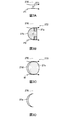
- FIG. 3A schematically shows the state of the primary target 271 when the primary target 271 is irradiated with the first prepulse laser beam P1 in the EUV light generation system 11 shown in FIG.
- FIG. 3B schematically shows the state of the secondary target 272 when the secondary pre-pulse laser beam P2 is irradiated to the secondary target 272 in the EUV light generation system 11 shown in FIG.
- FIG. 1 schematically shows the configuration of an exemplary LPP type EUV light generation system.
- FIG. 2 is a partial cross-sectional view showing the configuration of the EUV light generation system 11 according to the comparative example.
- FIG. 3A schematically shows the state of the primary target 271 when the primary target 271 is irradiated with the first prepulse laser beam P1 in
- FIG. 3C schematically shows the state of the tertiary target 273 when the main pulse laser beam M is irradiated to the tertiary target 273 in the EUV light generation system 11 shown in FIG. 2.
- FIG. 3D shows an emission region 27e of EUV light.
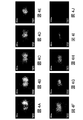
- 4A to 4J show images obtained by capturing the tertiary target 273 with visible light at every elapsed time after irradiation with the second pre-pulse laser beam P2.
- FIG. 5 is a graph showing changes in emission intensity obtained from the images shown in FIGS. 4A to 4J.
- FIG. 6A schematically shows the state of the tertiary target 273 when the main pulse laser beam M is irradiated to the tertiary target 273 in a state where the plasma 27d and ions contained therein are lost.
- FIG. 6B shows an emission region 27f of EUV light.
- FIG. 7 is a graph showing the measurement results of CE in the EUV light generation system.
- FIG. 8 schematically illustrates an EUV light generation system 11a according to the first embodiment of the present disclosure.
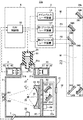
- FIG. 9 schematically illustrates an EUV light generation system 11b according to the second embodiment of the present disclosure.
- General description of extreme ultraviolet light generation system 1.1 Configuration 1.2 Operation EUV light generation system for irradiating a target with first to third laser beams 2.1 Configuration 2.1.1 Target supply unit 2.1.2 Target sensor and light emitting unit 2.1.3 Laser system 2.1.4 Laser beam traveling direction control unit 2.1.5 Condensing optical system and EUV collector mirror 2.2 Operation 2.2.1 Target output 2.2.2 Target detection 2.2.3 Pulse laser beam output 2.2.4 Transmission of pulsed laser light 2.2.5 Condensing of pulsed laser light 2.3 Change of target irradiated with pulsed laser light 2.3.1 Primary target 271 2.3.2 Secondary target 272 2.3.3 Tertiary target 273 2.4 Issues 2.5 Behavior of tertiary target 273 2.6 Main pulse irradiation after ion disappearance 3.
- EUV light generation system having a timer for measuring the time after irradiation with the second pre-pulse laser beam P2. 3.1 Example in which the timer holds the required time 3.2 Example in which the memory holds the required time 3.3 Others EUV light generation system equipped with an ion detector 4.1 Example of continuously monitoring the presence or absence of ions 4.2 Example of determining the presence or absence of ions at a specific timing 4.3 Other 5. Supplement
- FIG. 1 schematically shows a configuration of an exemplary LPP type EUV light generation system.
- the EUV light generation apparatus 1 is used with at least one laser system 3.
- a system including the EUV light generation apparatus 1 and the laser system 3 is referred to as an EUV light generation system 11.
- the EUV light generation apparatus 1 includes a chamber 2 and a target supply unit 26.
- the chamber 2 is configured to be hermetically sealed.
- the target supply unit 26 is attached so as to penetrate the wall of the chamber 2, for example.
- the material of the target substance output from the target supply unit 26 may include, but is not limited to, tin, terbium, gadolinium, lithium, xenon, or a combination of any two or more thereof.
- the wall of the chamber 2 is provided with at least one through hole.
- a window 21 is provided in the through hole.
- the pulse laser beam 32 output from the laser system 3 is transmitted through the window 21.
- an EUV collector mirror 23 having a spheroidal reflecting surface is disposed inside the chamber 2, for example.
- the EUV collector mirror 23 has first and second focal points.
- the EUV collector mirror 23 is disposed, for example, such that its first focal point is located in the plasma generation region 25 and its second focal point is located in the intermediate focal point (IF) 292.
- a through hole 24 is provided at the center of the EUV collector mirror 23.
- the pulse laser beam 33 passes through the through hole 24.
- the EUV light generation apparatus 1 includes an EUV light generation control unit 5, a target sensor 4, and the like.
- the target sensor 4 has an imaging function and is configured to detect the presence, locus, position, speed, and the like of the target 27.
- the EUV light generation apparatus 1 includes a connection portion 29 that allows communication between the inside of the chamber 2 and the inside of the exposure apparatus 6.
- a wall 291 having an aperture is provided in the connection portion 29. The wall 291 is disposed such that its aperture is located at the second focal position of the EUV collector mirror 23.
- the EUV light generation apparatus 1 includes a laser beam traveling direction control unit 34, a laser beam focusing mirror 22, a target recovery unit 28 for recovering the target 27, and the like.
- the laser beam traveling direction control unit 34 includes an optical element for defining the traveling direction of the laser beam and an actuator for adjusting the position, posture, and the like of the optical element.
- the pulsed laser beam 31 output from the laser system 3 passes through the window 21 as the pulsed laser beam 32 through the laser beam traveling direction control unit 34 and enters the chamber 2. .
- the pulsed laser light 32 travels in the chamber 2 along at least one laser light path, is reflected by the laser light focusing mirror 22, and is irradiated onto at least one target 27 as pulsed laser light 33.
- the target supply unit 26 outputs the target 27 toward the plasma generation region 25 inside the chamber 2.
- the target 27 is irradiated with at least one pulse included in the pulse laser beam 33.
- the target 27 irradiated with the pulse laser beam is turned into plasma, and radiation light 251 is emitted from the plasma.
- the EUV collector mirror 23 reflects EUV light included in the emitted light 251 with a higher reflectance than light in other wavelength ranges.
- the reflected light 252 including the EUV light reflected by the EUV collector mirror 23 is condensed at the intermediate condensing point 292 and output to the exposure device 6.
- a single target 27 may be irradiated with a plurality of pulses included in the pulse laser beam 33.
- the EUV light generation controller 5 controls the entire EUV light generation system 11.
- the EUV light generation controller 5 processes the image data of the target 27 imaged by the target sensor 4. Further, the EUV light generation control unit 5 controls, for example, the timing at which the target 27 is output, the output direction of the target 27, and the like. Further, the EUV light generation control unit 5 controls, for example, the oscillation timing of the laser system 3, the traveling direction of the pulse laser light 32, the focusing position of the pulse laser light 33, and the like.
- the various controls described above are merely examples, and other controls may be added as necessary.
- FIG. 2 is a partial cross-sectional view showing a configuration of an EUV light generation system 11 according to a comparative example.
- a condensing optical system 22 a, an EUV collector mirror 23, a target recovery unit 28, an EUV collector mirror holder 81, and plates 82 and 83 are provided inside the chamber 2. It has been.
- a target supply unit 26, a target sensor 4, and a light emitting unit 45 are attached to the chamber 2.
- the EUV light generation controller 5 includes an EUV controller 50.
- the target supply unit 26 includes a reservoir 61.
- a part of the reservoir 61 passes through a through hole 2 a formed in the wall surface of the chamber 2, and the tip of the reservoir 61 is located inside the chamber 2.
- An opening 62 is formed at the tip of the reservoir 61.
- a vibration device (not shown) is disposed near the opening 62 at the tip of the reservoir 61.
- the reservoir 61 stores the target material inside.
- a flange portion 61a of the reservoir 61 is fixed in close contact with the wall surface of the chamber 2 around the through hole 2a.
- the target sensor 4 and the light emitting unit 45 are arranged on opposite sides of the track of the target 27.
- Windows 21 a and 21 b are attached to the chamber 2.
- the window 21 a is located between the light emitting unit 45 and the trajectory of the target 27.
- the window 21 b is located between the trajectory of the target 27 and the target sensor 4.
- the target sensor 4 includes an optical sensor 41, a condensing optical system 42, and a container 43.
- the container 43 is fixed to the outside of the chamber 2.
- An optical sensor 41 and a condensing optical system 42 are fixed inside the container 43.
- the light emitting unit 45 includes a light source 46, a condensing optical system 47, and a container 48.
- the container 48 is fixed to the outside of the chamber 2.
- a light source 46 and a condensing optical system 47 are fixed inside the container 48.
- the laser system 3 includes a first prepulse laser apparatus La1, a second prepulse laser apparatus La2, and a main pulse laser apparatus Lb.
- Each of the first pre-pulse laser apparatus La1 and the second pre-pulse laser apparatus La2 is composed of, for example, a YAG laser apparatus.
- each of the first pre-pulse laser device La1 and the second pre-pulse laser device La2 is, Nd: consists of a laser device using a YVO 4.
- the main pulse laser device Lb is composed of a CO 2 laser device. These laser devices include a laser oscillator and optionally a laser amplifier.
- a YAG laser device is a laser device that uses a YAG crystal as a laser medium for either or both of a laser oscillator and a laser amplifier.
- the CO 2 laser device is a laser device that uses CO 2 gas as a laser medium for either or both of a laser oscillator and a laser amplifier.
- the laser beam traveling direction control unit 34a includes high reflection mirrors 340, 341, and 342 and beam combiners 343 and 344.
- the high reflection mirror 340 is supported by the holder 345.
- the high reflection mirror 341 is supported by a holder 346.
- the high reflection mirror 342 is supported by a holder 347.
- the beam combiner 343 is supported by a holder 348.
- the beam combiner 343 is composed of a polarizer.
- the beam combiner 344 is supported by the holder 349.
- the beam combiner 344 is composed of a dichroic mirror.
- the plate 82 is fixed to the chamber 2.
- a plate 83 and a position adjustment mechanism 84 are supported on the plate 82.
- the condensing optical system 22 a includes an off-axis parabolic mirror 221 and a plane mirror 222.
- the off-axis parabolic mirror 221 is supported by the holder 223.
- the plane mirror 222 is supported by the holder 224.
- the holders 223 and 224 are fixed to the plate 83.
- the EUV collector mirror 23 is fixed to the plate 82 via an EUV collector mirror holder 81.
- the EUV control unit 50 included in the EUV light generation control unit 5 outputs a control signal to the target supply unit 26.
- the target material in the reservoir 61 is maintained at a temperature equal to or higher than the melting point of the target material by a heater (not shown) provided in the reservoir 61.
- the target material in the reservoir 61 is pressurized by an inert gas supplied into the reservoir 61.
- the target material pressurized by the inert gas is output as a jet through the opening 62.
- the above-described vibration device applies vibration to the reservoir 61. By this vibration, the jet of the target material is separated into a plurality of droplets. Each droplet constitutes a target 27.
- the target 27 moves in the arrow Y direction along the trajectory from the target supply unit 26 to the plasma generation region 25.
- the target recovery unit 28 recovers the target 27 that has passed through the plasma generation region 25.
- the light emitting unit 45 condenses the output light of the light source 46 at a substantially orbital position of the target 27 between the target supply unit 26 and the plasma generation region 25.
- the target 27 passes through the light condensing position by the light emitting unit 45.
- the target sensor 4 detects a change in the light intensity of the light passing through the trajectory of the target 27 and its surroundings.
- the target sensor 4 outputs a target detection signal based on the change in light intensity.
- the EUV control unit 50 receives this target detection signal.
- the EUV controller 50 outputs a first trigger signal to the first pre-pulse laser apparatus La1 based on the target detection signal.
- the first trigger signal is output when the first delay time has elapsed with respect to the reception timing of the target detection signal.
- the first prepulse laser apparatus La1 outputs the first prepulse laser beam P1 according to the first trigger signal.
- the first prepulse laser light P1 corresponds to the first laser light in the present disclosure.
- the EUV control unit 50 outputs the second trigger signal to the second prepulse laser apparatus La2.
- the second trigger signal is output when a second delay time longer than the first delay time has elapsed with respect to the reception timing of the target detection signal.
- the second prepulse laser apparatus La2 outputs the second prepulse laser beam P2 according to the second trigger signal.
- the second prepulse laser beam P2 corresponds to the second laser beam in the present disclosure.
- the EUV control unit 50 outputs a third trigger signal to the main pulse laser device Lb.
- the third trigger signal is output when a third delay time longer than the second delay time has elapsed with respect to the reception timing of the target detection signal.
- the main pulse laser device Lb outputs the main pulse laser beam M in accordance with the third trigger signal.
- the main pulse laser beam M corresponds to the third laser beam in the present disclosure.
- the laser system 3 outputs the first pre-pulse laser beam P1, the second pre-pulse laser beam P2, and the main pulse laser beam M in this order.
- the first pre-pulse laser beam P1 preferably has a pulse time width on the order of picoseconds.
- the picosecond order means 1 ps or more and less than 1 ns.
- the pulse time width of the second pre-pulse laser beam P2 is preferably shorter than the pulse time width of the main pulse laser beam M.
- a delay circuit (not shown) may measure the first to third delay times, and the delay circuit may output the first to third trigger signals to the respective laser devices.
- the high reflection mirror 340 included in the laser beam traveling direction control unit 34a is disposed in the optical path of the first prepulse laser beam P1 output by the first prepulse laser apparatus La1.
- the high reflection mirror 340 reflects the first pre-pulse laser beam P1 with a high reflectance.
- the beam combiner 343 is disposed at a position where the optical path of the first prepulse laser beam P1 reflected by the high reflection mirror 340 and the optical path of the second prepulse laser beam P2 output by the second prepulse laser apparatus La2 intersect. Yes.
- the first prepulse laser beam P1 is linearly polarized light whose polarization direction is parallel to the paper surface.
- the second prepulse laser beam P2 is a linearly polarized light whose polarization direction is perpendicular to the paper surface.
- the first pre-pulse laser beam P1 enters the beam combiner 343 from the upper side in the drawing.
- the second pre-pulse laser beam P2 enters the beam combiner 343 from the left side in the drawing.
- the polarizer constituting the beam combiner 343 transmits the first prepulse laser beam P1 with a high transmittance and reflects the second prepulse laser beam P2 with a high reflectance.
- the beam combiner 343 guides the first prepulse laser beam P1 and the second prepulse laser beam P2 to the beam combiner 344 with substantially the same optical path axis.
- the high reflection mirrors 341 and 342 are arranged in the optical path of the main pulse laser beam M output by the main pulse laser device Lb.
- the high reflection mirrors 341 and 342 sequentially reflect the main pulse laser beam M with high reflectivity.
- the beam combiner 344 is disposed at a position where the optical paths of the first pre-pulse laser beam P1 and the second pre-pulse laser beam P2 intersect with the optical path of the main pulse laser beam M reflected by the high reflection mirror 342.
- the first prepulse laser beam P1 and the second prepulse laser beam P2 include a first wavelength component.
- the main pulse laser beam M includes a second wavelength component different from the first wavelength component.
- the first pre-pulse laser beam P1 and the second pre-pulse laser beam P2 enter the beam combiner 344 from the upper side in the drawing.
- the main pulse laser beam M enters the beam combiner 344 from the right side in the figure.
- the dichroic mirror constituting the beam combiner 344 reflects the first prepulse laser light P1 and the second prepulse laser light P2 including the first wavelength component with high reflectivity, and the main pulse laser light M including the second wavelength component. Is transmitted with high transmittance.
- the beam combiner 344 causes the optical path axes of the first pre-pulse laser beam P1, the second pre-pulse laser beam P2, and the main pulse laser beam M to substantially coincide with each other and guides them to the condensing optical system 22a as the pulse laser beam 32.
- the beam combiner 343 can also be configured with a dichroic mirror.
- the off-axis parabolic mirror 221 included in the condensing optical system 22 a is disposed in the optical path of the pulse laser light 32.
- the off-axis parabolic mirror 221 reflects the pulsed laser light 32 toward the plane mirror 222.
- the plane mirror 222 reflects the pulse laser beam 32 reflected by the off-axis paraboloid mirror 221 as the pulse laser beam 33.
- the pulsed laser light 33 is condensed according to the shape of the reflecting surface of the off-axis parabolic mirror 221.
- the position adjustment mechanism 84 adjusts the position of the plate 83 with respect to the plate 82.
- the position adjustment mechanism 84 is controlled by a control signal output from the EUV control unit 50.
- the positions of the off-axis paraboloidal mirror 221 and the plane mirror 222 are adjusted.
- the positions of the off-axis paraboloid mirror 221 and the plane mirror 222 are adjusted so that the pulse laser beam 33 reflected by these mirrors is collected in the plasma generation region 25.
- one target 27 is irradiated with the first prepulse laser beam P1, the second prepulse laser beam P2, and the main pulse laser beam M in this order.
- a primary target 271, a secondary target 272, and a tertiary target 273, which will be described later with reference to FIGS. 3A to 3C, are collectively referred to as “target 27”.
- the target 27 When the target 27 is irradiated with the first pre-pulse laser beam P1, the second pre-pulse laser beam P2, and the main pulse laser beam M, the target 27 is turned into plasma, and EUV light is generated from this plasma.
- the present disclosure is not limited to this, and the target may be irradiated with the fourth laser light between the first prepulse laser light P1 and the second prepulse laser light P2.
- the fifth laser beam may be irradiated on the target between the second pre-pulse laser beam P2 and the main pulse laser beam M.
- FIGS. 3A, 3B, and 3C are respectively the first prepulse laser light P1 and the second prepulse laser light P2 in the EUV light generation system 11 shown in FIG.
- the state of the target when the main pulse laser beam M is irradiated is schematically shown.
- the density of the dots in FIGS. 3B and 3C corresponds to the density of the target material.
- FIG. 3C shows a case where the main pulse laser beam M is irradiated after the irradiation of the second prepulse laser beam P2 and before the ions of the target material disappear.
- the first pre-pulse laser beam P1, the second pre-pulse laser beam P2, and the main pulse laser beam M are irradiated from the left side to the right side of each drawing.
- a broken line 270 indicates the trajectory of the target 27 and its extension line.
- FIG. 3A shows the primary target 271.
- the target 27 after being output from the target supply unit 26 and before being irradiated with the first prepulse laser beam P ⁇ b> 1 is referred to as a primary target 271.
- the primary target 271 has a droplet shape. When the primary target 271 reaches the plasma generation region 25, the primary target 271 is irradiated with the first prepulse laser beam P1.
- FIG. 3B shows the secondary target 272.
- the target 27 after being irradiated with the first prepulse laser beam P1 and before being irradiated with the second prepulse laser beam P2 is referred to as a secondary target 272.
- the secondary target 272 includes a plurality of fine particles.
- the secondary target 272 generated by irradiating the first pre-pulse laser beam P1 having a pulse time width on the order of picoseconds has an annular portion 27a and a dome portion 27b.
- the annular portion 27a is a region where the target material diffuses to the downstream side of the optical path of the first pre-pulse laser beam P1 and the density of the target material is relatively high.
- the dome portion 27b is a region where the target material diffuses to the upstream side of the optical path of the first prepulse laser beam P1, and the density of the target material is relatively low.
- the upstream side of the optical path refers to the direction approaching the light source along the optical path
- the downstream side of the optical path refers to the direction away from the light source along the optical path.
- the secondary target 272 is irradiated with the second pre-pulse laser beam P2.
- FIG. 3C shows the tertiary target 273.
- the target 27 before the main pulse laser beam M is irradiated after the second prepulse laser beam P2 is irradiated is referred to as a tertiary target 273.
- the tertiary target 273 includes a plurality of fine particles.
- the tertiary target 273 may further include steam.
- a region where a plurality of fine particles and vapor are dispersed is defined as a dispersion region 27c.
- the target material distributed at high density in the annular portion 27a in the secondary target 272 described above is diffused by the irradiation of the second prepulse laser beam P2, and the uneven density of the target material is suppressed.
- the tertiary target 273 may further include plasma 27d.
- the plasma 27d contains ions of the target material.
- the plasma 27d is located upstream of the optical path of the second pre-pulse laser beam P2 in the tertiary target 273. It is considered that the plasma 27d is generated because a part of the dome portion 27b of the secondary target 272 absorbs most of the energy of the second prepulse laser beam P2.
- the tertiary pulse 273 is irradiated with the main pulse laser beam M.
- the density of the target material is low in the fine plural fine particles and vapor dispersion region 27 c included in the tertiary target 273. For this reason, the fine fine particles and vapor contained in the tertiary target 273 are likely to absorb the energy of the main pulse laser beam M. If the tertiary target 273 efficiently absorbs the energy of the main pulse laser beam M, the tertiary target 273 is efficiently turned into plasma.
- ions contained in the plasma 27d of the tertiary target 273 may reflect or absorb the main pulse laser beam M.
- the main pulse laser beam M when irradiating CO 2 laser light to ions, there is a report that if the ion density exceeds 10 16 atoms / cm 3 , the component of the laser light reflected or absorbed by the ions increases. Of the energy of the main pulse laser beam M, the portion reflected or absorbed by the ions contained in the plasma 27d may not reach the dispersion region 27c.
- FIG. 3D shows the EUV light emission region 27e.
- the plasma 27d is heated to a high temperature.
- the EUV light emission region 27e may be a narrow region equivalent to the region of the plasma 27d shown in FIG. 3C.
- the conversion efficiency from laser light energy to EUV light energy may be low. This conversion efficiency is referred to as CE.
- 4A to 4J show images obtained by capturing the tertiary target 273 with visible light at every elapsed time after irradiation with the second pre-pulse laser beam P2.
- the first image shown in FIG. 4A is an image when 10 ns has elapsed from the irradiation of the second pre-pulse laser beam P2, and the second and subsequent images shown in FIGS. 4B to 4J have further passed 10 ns. It is an image of time.
- 4J corresponds to an image when 100 ns has elapsed from the irradiation of the second pre-pulse laser beam P2.
- 4A to 4J it is assumed that the second prepulse laser beam P2 is irradiated in the direction from the right side to the left side in the drawing, unlike the irradiation direction of the second prepulse laser beam P2 in FIG. 3B.
- the center of FIGS. 4A to 4J corresponds to the approximate center of the plasma generation region 25.
- FIG. 5 is a graph showing changes in emission intensity obtained from the images shown in FIGS. 4A to 4J.
- the emission intensity shown in FIG. 5 is a value calculated using an integral value of luminance along the beam center axis of the second prepulse laser beam P2 in these images, and is 10 ns from the irradiation of the second prepulse laser beam P2. It is a relative value when the value when elapsed is 1.
- the beam center axis of the second prepulse laser beam P2 is a horizontal straight line that passes through substantially the center of FIGS. 4A to 4J.
- a strong light emission region having a substantially crescent shape exists on the upstream side of the optical path of the second prepulse laser beam P2.
- the shape of the light emitting region is considered to correspond to the shape of the plasma 27d shown in FIG. 3C.
- FIG. 6A shows the state of the tertiary target 273 when the main pulse laser beam M is irradiated to the tertiary target 273 in a state where the plasma 27d and ions contained therein are lost. Shown schematically. After the irradiation with the second prepulse laser beam P2, if the plasma 27d and ions contained therein disappear, it is considered that a plurality of fine particles and vapor remain in the dispersion region 27c. Such fine particles and vapor are distinguished from ions and are called neutral particles.
- FIG. 6B shows an EUV light emission region 27f.
- the energy of the main pulse laser beam M reaches almost the entire dispersion region 27c, it is expected that many parts of the tertiary target 273 are turned into plasma.
- the EUV light emission region 27f is wider than the EUV light emission region 27e when the main pulse laser light M is irradiated to the plasma 27d and ions contained therein. Thereby, it is thought that CE improves.
- FIG. 7 is a graph showing the measurement results of CE in the EUV light generation system.
- the horizontal axis indicates the irradiation timing of the second pre-pulse laser beam P2
- the vertical axis indicates CE.
- the irradiation timing of the second pre-pulse laser beam P ⁇ b> 2 is shown as a time traced back from the irradiation timing of the main pulse laser beam M when the irradiation timing of the main pulse laser beam M is 0.
- CE was measured under the following conditions. As the target 27, liquid tin was used. The diameter of the target 27 was in the range of 21 ⁇ m to 22 ⁇ m.
- the first pre-pulse laser beam P1 a pulse laser beam having a wavelength of 1.06 ⁇ m was used.
- the pulse width due to the full width at half maximum of the first prepulse laser beam P1 was 14 ps.
- the condensed diameter of the first prepulse laser beam P1 was set to 70 ⁇ m when expressed by the diameter of the portion having a light intensity of 1 / e 2 or more of the peak intensity at the target irradiation position.
- the fluence of the first prepulse laser beam P1 was set to 5.2 J / cm 2 .
- the irradiation timing of the first pre-pulse laser beam P1 was set to ⁇ 1.1 ⁇ s, retrospectively from the irradiation timing of the main pulse laser beam M, when the irradiation timing of the main pulse laser beam M was set to 0.
- the second pre-pulse laser beam P2 a pulse laser beam having a wavelength of 1.06 ⁇ m was used.
- the pulse width due to the full width at half maximum of the second pre-pulse laser beam P2 was 5 ns.
- the condensing diameter of the second prepulse laser beam P2 was 400 ⁇ m when expressed by the diameter of the portion having a light intensity of 1 / e 2 or more of the peak intensity at the target irradiation position.
- fluence of the second pre-pulse laser beam P2 2.4J / cm 2, 1.6J / cm 2, was set four types of 0.8 J / cm 2, and 0 J / cm 2.
- the case of 0 J / cm 2 corresponds to the case where the second pre-pulse laser beam P2 is not irradiated. Then, CE was measured while changing the irradiation timing of the second prepulse laser beam P2 in the range of ⁇ 0.6 ⁇ s to 0 ⁇ s for each fluence setting value of the second prepulse laser beam P2.
- the main pulse laser beam M a pulse laser beam having a wavelength of 10.6 ⁇ m was used.
- the pulse width due to the full width at half maximum of the main pulse laser beam M was 15 ns.
- the condensing diameter of the main pulse laser beam M was set to 300 ⁇ m when expressed by the diameter of the portion having a light intensity of 1 / e 2 or more of the peak intensity at the irradiation position on the target.
- the density of ions of the target irradiated with the main pulse laser beam M is 10 16 atoms / cm 3 or less, which is high. It can be inferred that CE was obtained. However, after 300 ns have elapsed from the irradiation of the second pre-pulse laser beam P2, the density of the tertiary target 273 may be outside the optimum range.
- the target is irradiated with the main pulse laser beam M after ions generated by the irradiation with the second pre-pulse laser beam P2 disappear.
- the energy of the main pulse laser beam is efficiently absorbed by the target, and CE is improved.
- “ion disappeared” may mean that the density of ions on the optical path of the main pulse laser beam M is 10 16 atoms / cm 3 or less.
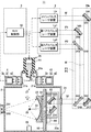
- FIG. 8 schematically shows an EUV light generation system 11a according to the first embodiment of the present disclosure.
- the EUV light generation controller 5 includes a timer 52 and a memory 53 in addition to the EUV controller 50 described above.
- the EUV control unit 50 is configured to output a timer measurement start signal synchronized with the second trigger signal to the timer 52.
- the EUV control unit 50 is configured to receive the output signal of the timer 52.
- the EUV controller 50 is configured to output the third trigger signal based on the output signal of the timer 52.
- the timer 52 is configured to receive a timer measurement start signal from the EUV control unit 50.
- the timer 52 is configured to measure the time after receiving the timer measurement start signal.
- the timer 52 outputs an output signal indicating the end of measurement to the EUV control unit 50 when the measurement for a predetermined time period is completed.
- the predetermined period of time corresponds to a time required until ions generated by irradiation with the second pre-pulse laser beam P2 disappear. This required time is, for example, 100 ns or more and 300 ns or less.
- the timer 52 outputs an output signal indicating the time after receiving the measurement start signal of the timer to the EUV control unit 50 as needed instead of measuring a predetermined time. May be.
- the EUV control unit 50 reads in advance data of the time required until the ions generated by the irradiation of the second pre-pulse laser beam P2 disappear from the memory 53.
- This required time is, for example, 100 ns or more and 300 ns or less.
- the memory 53 may hold a plurality of values as the required time data, for example, according to the required EUV light energy value.
- the EUV control unit 50 compares the time after the start of measurement received from the timer 52 with the required time read from the memory 53.
- the EUV control unit 50 outputs the third trigger signal when the time after the start of measurement received from the timer 52 reaches the required time read from the memory 53.
- the memory 53 corresponds to a storage unit in the present disclosure.
- the main pulse laser beam M is irradiated to the target.
- “Ions disappeared” means that ions have disappeared at least from the optical path of the main pulse laser beam M, and ions may exist outside the optical path of the main pulse laser beam M.
- the main pulse laser beam M is applied to the neutral particles that remain after the ions of the elements constituting the target disappear.
- the main pulse laser beam M is controlled so as to be irradiated to a part of the target but not to ions of elements constituting the target.
- the main pulse laser beam M is irradiated to a target whose ion density is 10 16 atoms / cm 3 or less.
- the target 27 can be irradiated with the main pulse laser beam M by accurately measuring the time required until the ions generated by the irradiation of the second pre-pulse laser beam P2 disappear. Thereby, CE can be improved. It is not always necessary to confirm whether or not ions have disappeared, and the required time may be obtained in advance by experiments.
- FIG. 9 schematically illustrates an EUV light generation system 11b according to the second embodiment of the present disclosure.
- an ion detector 7 is attached to the chamber 2.
- the ion detector 7 includes an optical sensor (not shown) and an optical system (not shown).
- the optical sensor is composed of a photodiode, for example.
- the optical system is configured to collect light in the vicinity of the plasma generation region 25 on a photodiode.
- an electromotive force is generated in the photodiode and a current flows. This current is output to the EUV controller 50 as an ion detection signal.
- the ion detector 7 may include an ion collector disposed in the vicinity of the plasma generation region 25.
- the ion collector includes a grid electrode (not shown) and a cathode electrode (not shown).
- the grid electrode is disposed between the plasma generation region 25 and the cathode electrode so as to be separated from the cathode electrode.
- a negative potential is applied to the grid electrode.
- a buffer circuit (not shown) is connected to the cathode electrode. When ions pass through the grid electrode and reach the cathode electrode, the potential of the cathode electrode rises and a current flows through the buffer circuit. This current is output to the EUV controller 50 as an ion detection signal.
- the EUV controller 50 monitors the ion detection signal from the ion detector 7 after outputting the second trigger signal to the second prepulse laser device La2.
- the EUV control unit 50 sets the time difference from the second trigger signal to the third trigger signal so that the third trigger signal is output after the ion detector 7 no longer detects ions.
- the ion detector 7 may include a camera (not shown) that captures an image of a light emitting source in the vicinity of the plasma generation region 25.
- the camera has a high-speed shutter.
- the high-speed shutter is controlled by the EUV control unit 50 so as to open and close at a predetermined timing after the EUV control unit 50 outputs the second trigger signal.
- the EUV control unit 50 opens and closes the high-speed shutter of the camera when, for example, 100 ns elapses after outputting the second trigger signal.
- the EUV controller 50 outputs a third trigger signal after opening and closing the high-speed shutter.
- the EUV control unit 50 measures the luminance of a predetermined portion of the image captured by the camera. If the luminance does not exceed a predetermined value, the EUV control unit 50 determines that ions have disappeared, and maintains the opening / closing timing of the high-speed shutter and the output timing of the third trigger signal.
- the EUV control unit 50 determines that ions are not lost, and changes the opening / closing timing of the high-speed shutter from, for example, 100 ns to 110 ns.
- the EUV control unit 50 also changes the output timing of the third trigger signal in accordance with the change in the opening / closing timing of the high-speed shutter.
- the target is irradiated with the main pulse laser beam M after ions generated by irradiation with the second pre-pulse laser beam P2 disappear.
- “Ions disappeared” means that ions have disappeared at least from the optical path of the main pulse laser beam M, and ions may exist outside the optical path of the main pulse laser beam M.
- the main pulse laser beam M is applied to the neutral particles that remain after the ions of the elements constituting the target disappear.
- the main pulse laser beam M is controlled so as to be irradiated to a part of the target but not to ions of elements constituting the target.
- the main pulse laser beam M is irradiated to a target whose ion density is 10 16 atoms / cm 3 or less.
- the second embodiment it is possible to determine whether or not ions have disappeared and irradiate the target 27 with the main pulse laser beam M at an appropriate timing. Thereby, CE can be improved. It is not always necessary to obtain the time required until ions disappear, and it is possible to flexibly respond to changes in operating conditions such as the required EUV light energy value and the fluence value of the second prepulse laser beam P2. it can.
Landscapes
- Physics & Mathematics (AREA)
- Optics & Photonics (AREA)
- Engineering & Computer Science (AREA)
- Plasma & Fusion (AREA)
- Exposure And Positioning Against Photoresist Photosensitive Materials (AREA)
- X-Ray Techniques (AREA)
Abstract
極端紫外光生成装置は、所定領域に向けてターゲットを出力するターゲット供給部と、ターゲットに照射される第1レーザ光と、第1レーザ光が照射されたターゲットに照射される第2レーザ光と、第2レーザ光が照射されたターゲットに照射される第3レーザ光と、を出力するレーザシステムと、少なくとも第3レーザ光の光路からターゲットを構成する元素のイオンが消失した後に第3レーザ光がターゲットに照射されるように、レーザシステムを制御する制御部と、を備える。
Description
本開示は、極端紫外光生成装置に関する。
近年、半導体プロセスの微細化に伴って、半導体プロセスの光リソグラフィにおける転写パターンの微細化が急速に進展している。次世代においては、70nm~45nmの微細加工、さらには32nm以下の微細加工が要求されるようになる。このため、例えば32nm以下の微細加工の要求に応えるべく、波長13nm程度の極端紫外(EUV)光を生成する極端紫外光生成装置と縮小投影反射光学系(reduced projection reflection optics)とを組み合わせた露光装置の開発が期待されている。
EUV光生成装置としては、ターゲット物質にパルスレーザ光を照射することによって生成されるプラズマが用いられるLPP(Laser Produced Plasma)式の装置と、放電によって生成されるプラズマが用いられるDPP(Discharge Produced Plasma)式の装置と、シンクロトロン放射光が用いられるSR(Synchrotron Radiation)式の装置との3種類の装置が提案されている。
本開示の1つの観点に係る極端紫外光生成装置は、所定領域に向けてターゲットを出力するターゲット供給部と、ターゲットに照射される第1レーザ光と、第1レーザ光が照射されたターゲットに照射される第2レーザ光と、第2レーザ光が照射されたターゲットに照射される第3レーザ光と、を出力するレーザシステムと、少なくとも第3レーザ光の光路からターゲットを構成する元素のイオンが消失した後に第3レーザ光がターゲットに照射されるように、レーザシステムを制御する制御部と、を備える。
本開示の他の1つの観点に係る極端紫外光生成装置は、所定領域に向けてターゲットを出力するターゲット供給部と、ターゲットに照射される第1レーザ光と、第1レーザ光が照射されたターゲットに照射される第2レーザ光と、第2レーザ光が照射されたターゲットに照射される第3レーザ光と、を出力するレーザシステムと、ターゲットを構成する元素のイオンが消失して残留した中性粒子に第3レーザ光が照射されるようにレーザシステムを制御する制御部と、を備える。
本開示の他の1つの観点に係る極端紫外光生成装置は、所定領域に向けてターゲットを出力するターゲット供給部と、ターゲットに照射される第1レーザ光と、第1レーザ光が照射されたターゲットに照射される第2レーザ光と、第2レーザ光が照射されたターゲットに照射される第3レーザ光と、を出力するレーザシステムと、第3レーザ光が、ターゲットの一部に照射されるがターゲットを構成する元素のイオンには照射されないように、レーザシステムを制御する制御部と、を備える。
本開示のいくつかの実施形態を、単なる例として、添付の図面を参照して以下に説明する。
図1は、例示的なLPP式のEUV光生成システムの構成を概略的に示す。
図2は、比較例に係るEUV光生成システム11の構成を示す一部断面図である。
図3Aは、図2に示されるEUV光生成システム11において1次ターゲット271に第1プリパルスレーザ光P1が照射されるときの1次ターゲット271の様子を概略的に示す。図3Bは、図2に示されるEUV光生成システム11において2次ターゲット272に第2プリパルスレーザ光P2が照射されるときの2次ターゲット272の様子を概略的に示す。図3Cは、図2に示されるEUV光生成システム11において3次ターゲット273にメインパルスレーザ光Mが照射されるときの3次ターゲット273の様子を概略的に示す。図3Dは、EUV光の発光領域27eを示す。
図4A~図4Jは、第2プリパルスレーザ光P2照射後の経過時間ごとにおける3次ターゲット273を可視光により撮像した画像を示す。
図5は、図4A~図4Jに示される画像から得られた発光強度の変化を示すグラフである。
図6Aは、プラズマ27d及びこれに含まれるイオンが消失した状態の3次ターゲット273にメインパルスレーザ光Mが照射されるときの3次ターゲット273の様子を概略的に示す。図6Bは、EUV光の発光領域27fを示す。
図7は、EUV光生成システムにおけるCEの測定結果を示すグラフである。
図8は、本開示の第1の実施形態に係るEUV光生成システム11aを概略的に示す。
図9は、本開示の第2の実施形態に係るEUV光生成システム11bを概略的に示す。
<内容>
1.極端紫外光生成システムの全体説明
1.1 構成
1.2 動作
2.第1~第3レーザ光をターゲットに照射するEUV光生成システム
2.1 構成
2.1.1 ターゲット供給部
2.1.2 ターゲットセンサ及び発光部
2.1.3 レーザシステム
2.1.4 レーザ光進行方向制御部
2.1.5 集光光学系及びEUV集光ミラー
2.2 動作
2.2.1 ターゲットの出力
2.2.2 ターゲットの検出
2.2.3 パルスレーザ光の出力
2.2.4 パルスレーザ光の伝送
2.2.5 パルスレーザ光の集光
2.3 パルスレーザ光を照射されたターゲットの変化
2.3.1 1次ターゲット271
2.3.2 2次ターゲット272
2.3.3 3次ターゲット273
2.4 課題
2.5 3次ターゲット273の挙動
2.6 イオン消失後のメインパルス照射
3.第2プリパルスレーザ光P2照射後の時間を計測するタイマーを備えたEUV光生成システム
3.1 所要時間をタイマーが保持する例
3.2 所要時間をメモリーが保持する例
3.3 その他
4.イオン検出器を備えたEUV光生成システム
4.1 継続的にイオンの有無を監視する例
4.2 特定タイミングでのイオンの有無を判定する例
4.3 その他
5.補足
1.極端紫外光生成システムの全体説明
1.1 構成
1.2 動作
2.第1~第3レーザ光をターゲットに照射するEUV光生成システム
2.1 構成
2.1.1 ターゲット供給部
2.1.2 ターゲットセンサ及び発光部
2.1.3 レーザシステム
2.1.4 レーザ光進行方向制御部
2.1.5 集光光学系及びEUV集光ミラー
2.2 動作
2.2.1 ターゲットの出力
2.2.2 ターゲットの検出
2.2.3 パルスレーザ光の出力
2.2.4 パルスレーザ光の伝送
2.2.5 パルスレーザ光の集光
2.3 パルスレーザ光を照射されたターゲットの変化
2.3.1 1次ターゲット271
2.3.2 2次ターゲット272
2.3.3 3次ターゲット273
2.4 課題
2.5 3次ターゲット273の挙動
2.6 イオン消失後のメインパルス照射
3.第2プリパルスレーザ光P2照射後の時間を計測するタイマーを備えたEUV光生成システム
3.1 所要時間をタイマーが保持する例
3.2 所要時間をメモリーが保持する例
3.3 その他
4.イオン検出器を備えたEUV光生成システム
4.1 継続的にイオンの有無を監視する例
4.2 特定タイミングでのイオンの有無を判定する例
4.3 その他
5.補足
以下、本開示の実施形態について、図面を参照しながら詳しく説明する。以下に説明される実施形態は、本開示のいくつかの例を示すものであって、本開示の内容を限定するものではない。また、各実施形態で説明される構成及び動作の全てが本開示の構成及び動作として必須であるとは限らない。なお、同一の構成要素には同一の参照符号を付して、重複する説明を省略する。
1.EUV光生成システムの全体説明
1.1 構成
図1に、例示的なLPP式のEUV光生成システムの構成を概略的に示す。EUV光生成装置1は、少なくとも1つのレーザシステム3と共に用いられる。本願においては、EUV光生成装置1及びレーザシステム3を含むシステムを、EUV光生成システム11と称する。図1に示し、かつ、以下に詳細に説明するように、EUV光生成装置1は、チャンバ2、ターゲット供給部26を含む。チャンバ2は、密閉可能に構成されている。ターゲット供給部26は、例えば、チャンバ2の壁を貫通するように取り付けられている。ターゲット供給部26から出力されるターゲット物質の材料は、スズ、テルビウム、ガドリニウム、リチウム、キセノン、又は、それらの内のいずれか2つ以上の組合せを含むことができるが、これらに限定されない。
1.1 構成
図1に、例示的なLPP式のEUV光生成システムの構成を概略的に示す。EUV光生成装置1は、少なくとも1つのレーザシステム3と共に用いられる。本願においては、EUV光生成装置1及びレーザシステム3を含むシステムを、EUV光生成システム11と称する。図1に示し、かつ、以下に詳細に説明するように、EUV光生成装置1は、チャンバ2、ターゲット供給部26を含む。チャンバ2は、密閉可能に構成されている。ターゲット供給部26は、例えば、チャンバ2の壁を貫通するように取り付けられている。ターゲット供給部26から出力されるターゲット物質の材料は、スズ、テルビウム、ガドリニウム、リチウム、キセノン、又は、それらの内のいずれか2つ以上の組合せを含むことができるが、これらに限定されない。
チャンバ2の壁には、少なくとも1つの貫通孔が設けられている。その貫通孔には、ウインドウ21が設けられている。ウインドウ21をレーザシステム3から出力されるパルスレーザ光32が透過する。チャンバ2の内部には、例えば、回転楕円面形状の反射面を有するEUV集光ミラー23が配置されている。EUV集光ミラー23は、第1及び第2の焦点を有する。EUV集光ミラー23の表面には、例えば、モリブデンとシリコンとが交互に積層された多層反射膜が形成されている。EUV集光ミラー23は、例えば、その第1の焦点がプラズマ生成領域25に位置し、その第2の焦点が中間集光点(IF)292に位置するように配置されている。EUV集光ミラー23の中央部には貫通孔24が設けられている。貫通孔24をパルスレーザ光33が通過する。
EUV光生成装置1は、EUV光生成制御部5、ターゲットセンサ4等を含む。ターゲットセンサ4は、撮像機能を有し、ターゲット27の存在、軌跡、位置、速度等を検出するよう構成されている。
また、EUV光生成装置1は、チャンバ2の内部と露光装置6の内部とを連通させる接続部29を含む。接続部29内部には、アパーチャが形成された壁291が設けられている。壁291は、そのアパーチャがEUV集光ミラー23の第2の焦点位置に位置するように配置されている。
さらに、EUV光生成装置1は、レーザ光進行方向制御部34、レーザ光集光ミラー22、ターゲット27を回収するためのターゲット回収部28等を含む。レーザ光進行方向制御部34は、レーザ光の進行方向を規定するための光学素子と、この光学素子の位置、姿勢等を調整するためのアクチュエータとを備えている。
1.2 動作
図1を参照に、レーザシステム3から出力されたパルスレーザ光31は、レーザ光進行方向制御部34を経て、パルスレーザ光32としてウインドウ21を透過してチャンバ2内に入射する。パルスレーザ光32は、少なくとも1つのレーザ光経路に沿ってチャンバ2内を進み、レーザ光集光ミラー22で反射されて、パルスレーザ光33として少なくとも1つのターゲット27に照射される。
図1を参照に、レーザシステム3から出力されたパルスレーザ光31は、レーザ光進行方向制御部34を経て、パルスレーザ光32としてウインドウ21を透過してチャンバ2内に入射する。パルスレーザ光32は、少なくとも1つのレーザ光経路に沿ってチャンバ2内を進み、レーザ光集光ミラー22で反射されて、パルスレーザ光33として少なくとも1つのターゲット27に照射される。
ターゲット供給部26は、ターゲット27をチャンバ2内部のプラズマ生成領域25に向けて出力する。ターゲット27には、パルスレーザ光33に含まれる少なくとも1つのパルスが照射される。パルスレーザ光が照射されたターゲット27はプラズマ化し、そのプラズマから放射光251が放射される。EUV集光ミラー23は、放射光251に含まれるEUV光を、他の波長域の光に比べて高い反射率で反射する。EUV集光ミラー23によって反射されたEUV光を含む反射光252は、中間集光点292で集光され、露光装置6に出力される。なお、1つのターゲット27に、パルスレーザ光33に含まれる複数のパルスが照射されてもよい。
EUV光生成制御部5は、EUV光生成システム11全体の制御を統括する。EUV光生成制御部5は、ターゲットセンサ4によって撮像されたターゲット27のイメージデータ等を処理する。また、EUV光生成制御部5は、例えば、ターゲット27が出力されるタイミング、ターゲット27の出力方向等を制御する。さらに、EUV光生成制御部5は、例えば、レーザシステム3の発振タイミング、パルスレーザ光32の進行方向、パルスレーザ光33の集光位置等を制御する。上述の様々な制御は単なる例示に過ぎず、必要に応じて他の制御が追加されてもよい。
2.第1~第3レーザ光をターゲットに照射するEUV光生成システム
2.1 構成
図2は、比較例に係るEUV光生成システム11の構成を示す一部断面図である。図2に示されるように、チャンバ2の内部には、集光光学系22aと、EUV集光ミラー23と、ターゲット回収部28と、EUV集光ミラーホルダ81と、プレート82及び83とが設けられている。チャンバ2には、ターゲット供給部26と、ターゲットセンサ4と、発光部45とが取り付けられている。
2.1 構成
図2は、比較例に係るEUV光生成システム11の構成を示す一部断面図である。図2に示されるように、チャンバ2の内部には、集光光学系22aと、EUV集光ミラー23と、ターゲット回収部28と、EUV集光ミラーホルダ81と、プレート82及び83とが設けられている。チャンバ2には、ターゲット供給部26と、ターゲットセンサ4と、発光部45とが取り付けられている。
チャンバ2の外部には、レーザシステム3と、レーザ光進行方向制御部34aと、EUV光生成制御部5とが設けられている。EUV光生成制御部5は、EUV制御部50を含む。
2.1.1 ターゲット供給部
ターゲット供給部26は、リザーバ61を有する。リザーバ61の一部が、チャンバ2の壁面に形成された貫通孔2aを貫通しており、リザーバ61の先端がチャンバ2の内部に位置する。リザーバ61の上記先端には、開口62が形成されている。リザーバ61の上記先端の開口62付近に、図示しない加振装置が配置されている。リザーバ61は、ターゲット物質を内部に貯蔵している。貫通孔2aの周囲のチャンバ2の壁面には、リザーバ61のフランジ部61aが密着して固定されている。
ターゲット供給部26は、リザーバ61を有する。リザーバ61の一部が、チャンバ2の壁面に形成された貫通孔2aを貫通しており、リザーバ61の先端がチャンバ2の内部に位置する。リザーバ61の上記先端には、開口62が形成されている。リザーバ61の上記先端の開口62付近に、図示しない加振装置が配置されている。リザーバ61は、ターゲット物質を内部に貯蔵している。貫通孔2aの周囲のチャンバ2の壁面には、リザーバ61のフランジ部61aが密着して固定されている。
2.1.2 ターゲットセンサ及び発光部
ターゲットセンサ4と発光部45とは、ターゲット27の軌道を挟んで互いに反対側に配置されている。チャンバ2にはウインドウ21a及び21bが取り付けられている。ウインドウ21aは、発光部45とターゲット27の軌道との間に位置する。ウインドウ21bは、ターゲット27の軌道とターゲットセンサ4との間に位置する。
ターゲットセンサ4と発光部45とは、ターゲット27の軌道を挟んで互いに反対側に配置されている。チャンバ2にはウインドウ21a及び21bが取り付けられている。ウインドウ21aは、発光部45とターゲット27の軌道との間に位置する。ウインドウ21bは、ターゲット27の軌道とターゲットセンサ4との間に位置する。
ターゲットセンサ4は、光センサ41と、集光光学系42と、容器43とを含む。容器43はチャンバ2の外部に固定されている。容器43の内部に、光センサ41及び集光光学系42が固定されている。発光部45は、光源46と、集光光学系47と、容器48とを含む。容器48はチャンバ2の外部に固定されている。容器48の内部に、光源46及び集光光学系47が固定されている。
2.1.3 レーザシステム
レーザシステム3は、第1プリパルスレーザ装置La1と、第2プリパルスレーザ装置La2と、メインパルスレーザ装置Lbとを含む。第1プリパルスレーザ装置La1及び第2プリパルスレーザ装置La2の各々は、例えば、YAGレーザ装置で構成される。あるいは、第1プリパルスレーザ装置La1及び第2プリパルスレーザ装置La2の各々は、Nd:YVO4を用いたレーザ装置で構成される。メインパルスレーザ装置Lbは、CO2レーザ装置で構成される。これらのレーザ装置は、レーザ発振器及び必要に応じてレーザ増幅器を含む。YAGレーザ装置とは、レーザ発振器及びレーザ増幅器のいずれか又は両方に、レーザ媒質としてYAG結晶を用いるレーザ装置である。CO2レーザ装置とは、レーザ発振器及びレーザ増幅器のいずれか又は両方に、レーザ媒質としてCO2ガスを用いるレーザ装置である。
レーザシステム3は、第1プリパルスレーザ装置La1と、第2プリパルスレーザ装置La2と、メインパルスレーザ装置Lbとを含む。第1プリパルスレーザ装置La1及び第2プリパルスレーザ装置La2の各々は、例えば、YAGレーザ装置で構成される。あるいは、第1プリパルスレーザ装置La1及び第2プリパルスレーザ装置La2の各々は、Nd:YVO4を用いたレーザ装置で構成される。メインパルスレーザ装置Lbは、CO2レーザ装置で構成される。これらのレーザ装置は、レーザ発振器及び必要に応じてレーザ増幅器を含む。YAGレーザ装置とは、レーザ発振器及びレーザ増幅器のいずれか又は両方に、レーザ媒質としてYAG結晶を用いるレーザ装置である。CO2レーザ装置とは、レーザ発振器及びレーザ増幅器のいずれか又は両方に、レーザ媒質としてCO2ガスを用いるレーザ装置である。
2.1.4 レーザ光進行方向制御部
レーザ光進行方向制御部34aは、高反射ミラー340、341及び342と、ビームコンバイナ343及び344と、を含む。高反射ミラー340は、ホルダ345によって支持されている。高反射ミラー341は、ホルダ346によって支持されている。高反射ミラー342は、ホルダ347によって支持されている。
レーザ光進行方向制御部34aは、高反射ミラー340、341及び342と、ビームコンバイナ343及び344と、を含む。高反射ミラー340は、ホルダ345によって支持されている。高反射ミラー341は、ホルダ346によって支持されている。高反射ミラー342は、ホルダ347によって支持されている。
ビームコンバイナ343は、ホルダ348によって支持されている。ビームコンバイナ343は、偏光子で構成される。
ビームコンバイナ344は、ホルダ349によって支持されている。ビームコンバイナ344は、ダイクロイックミラーで構成される。
ビームコンバイナ344は、ホルダ349によって支持されている。ビームコンバイナ344は、ダイクロイックミラーで構成される。
2.1.5 集光光学系及びEUV集光ミラー
プレート82は、チャンバ2に固定されている。プレート82には、プレート83及び位置調整機構84が支持されている。集光光学系22aは、軸外放物面ミラー221及び平面ミラー222を含む。軸外放物面ミラー221は、ホルダ223によって支持されている。平面ミラー222は、ホルダ224によって支持されている。ホルダ223及び224は、プレート83に固定されている。
EUV集光ミラー23は、EUV集光ミラーホルダ81を介してプレート82に固定されている。
プレート82は、チャンバ2に固定されている。プレート82には、プレート83及び位置調整機構84が支持されている。集光光学系22aは、軸外放物面ミラー221及び平面ミラー222を含む。軸外放物面ミラー221は、ホルダ223によって支持されている。平面ミラー222は、ホルダ224によって支持されている。ホルダ223及び224は、プレート83に固定されている。
EUV集光ミラー23は、EUV集光ミラーホルダ81を介してプレート82に固定されている。
2.2 動作
2.2.1 ターゲットの出力
EUV光生成制御部5に含まれるEUV制御部50は、ターゲット供給部26に制御信号を出力する。
ターゲット供給部26において、リザーバ61内のターゲット物質は、リザーバ61に備えられた図示しないヒータによって、当該ターゲット物質の融点以上の温度に維持される。リザーバ61内のターゲット物質は、リザーバ61内に供給される不活性ガスによって加圧される。
2.2.1 ターゲットの出力
EUV光生成制御部5に含まれるEUV制御部50は、ターゲット供給部26に制御信号を出力する。
ターゲット供給部26において、リザーバ61内のターゲット物質は、リザーバ61に備えられた図示しないヒータによって、当該ターゲット物質の融点以上の温度に維持される。リザーバ61内のターゲット物質は、リザーバ61内に供給される不活性ガスによって加圧される。
不活性ガスによって加圧されたターゲット物質は、開口62を介して噴流として出力される。上述の加振装置は、リザーバ61に振動を与える。この振動により、ターゲット物質の噴流は複数のドロップレットに分離される。それぞれのドロップレットが、ターゲット27を構成する。ターゲット27は、ターゲット供給部26からプラズマ生成領域25までの軌道に沿って矢印Y方向に移動する。
ターゲット回収部28は、プラズマ生成領域25を通過したターゲット27を回収する。
ターゲット回収部28は、プラズマ生成領域25を通過したターゲット27を回収する。
2.2.2 ターゲットの検出
発光部45は、光源46の出力光を、ターゲット供給部26とプラズマ生成領域25との間のターゲット27のほぼ軌道上の位置に集光する。ターゲット27は、発光部45による光の集光位置を通過する。このとき、ターゲットセンサ4はターゲット27の軌道及びその周囲を通る光の光強度の変化を検出する。ターゲットセンサ4は、光強度の変化に基づいて、ターゲット検出信号を出力する。EUV制御部50は、このターゲット検出信号を受信する。
発光部45は、光源46の出力光を、ターゲット供給部26とプラズマ生成領域25との間のターゲット27のほぼ軌道上の位置に集光する。ターゲット27は、発光部45による光の集光位置を通過する。このとき、ターゲットセンサ4はターゲット27の軌道及びその周囲を通る光の光強度の変化を検出する。ターゲットセンサ4は、光強度の変化に基づいて、ターゲット検出信号を出力する。EUV制御部50は、このターゲット検出信号を受信する。
2.2.3 パルスレーザ光の出力
EUV制御部50は、ターゲット検出信号に基づいて、第1のトリガ信号を、第1プリパルスレーザ装置La1に出力する。第1のトリガ信号は、ターゲット検出信号の受信タイミングに対して第1の遅延時間が経過したときに出力される。第1プリパルスレーザ装置La1は、第1のトリガ信号に従って、第1プリパルスレーザ光P1を出力する。第1プリパルスレーザ光P1は、本開示における第1レーザ光に相当する。
EUV制御部50は、ターゲット検出信号に基づいて、第1のトリガ信号を、第1プリパルスレーザ装置La1に出力する。第1のトリガ信号は、ターゲット検出信号の受信タイミングに対して第1の遅延時間が経過したときに出力される。第1プリパルスレーザ装置La1は、第1のトリガ信号に従って、第1プリパルスレーザ光P1を出力する。第1プリパルスレーザ光P1は、本開示における第1レーザ光に相当する。
EUV制御部50は、第2のトリガ信号を、第2プリパルスレーザ装置La2に出力する。第2のトリガ信号は、ターゲット検出信号の受信タイミングに対して、第1の遅延時間より長い第2の遅延時間が経過したときに出力される。第2プリパルスレーザ装置La2は、第2のトリガ信号に従って、第2プリパルスレーザ光P2を出力する。第2プリパルスレーザ光P2は、本開示における第2レーザ光に相当する。
EUV制御部50は、第3のトリガ信号を、メインパルスレーザ装置Lbに出力する。第3のトリガ信号は、ターゲット検出信号の受信タイミングに対して、第2の遅延時間より長い第3の遅延時間が経過したときに出力される。メインパルスレーザ装置Lbは、第3のトリガ信号に従って、メインパルスレーザ光Mを出力する。メインパルスレーザ光Mは、本開示における第3レーザ光に相当する。
このように、レーザシステム3は、第1プリパルスレーザ光P1、第2プリパルスレーザ光P2、メインパルスレーザ光Mを、この順で出力する。第1プリパルスレーザ光P1は、ピコ秒オーダーのパルス時間幅を有することが好ましい。ピコ秒オーダーとは、1ps以上、1ns未満を意味する。第2プリパルスレーザ光P2のパルス時間幅は、メインパルスレーザ光Mのパルス時間幅より短いことが好ましい。図示しない遅延回路が第1~第3の遅延時間を計測し、この遅延回路が第1~第3のトリガ信号をそれぞれのレーザ装置に出力するようにしてもよい。
2.2.4 パルスレーザ光の伝送
レーザ光進行方向制御部34aに含まれる高反射ミラー340は、第1プリパルスレーザ装置La1によって出力された第1プリパルスレーザ光P1の光路に配置されている。高反射ミラー340は、第1プリパルスレーザ光P1を高い反射率で反射する。
レーザ光進行方向制御部34aに含まれる高反射ミラー340は、第1プリパルスレーザ装置La1によって出力された第1プリパルスレーザ光P1の光路に配置されている。高反射ミラー340は、第1プリパルスレーザ光P1を高い反射率で反射する。
ビームコンバイナ343は、高反射ミラー340によって反射された第1プリパルスレーザ光P1の光路と、第2プリパルスレーザ装置La2によって出力された第2プリパルスレーザ光P2の光路とが交差する位置に配置されている。
第1プリパルスレーザ光P1は、偏光方向が紙面に平行な直線偏光とされている。第2プリパルスレーザ光P2は、偏光方向が紙面に垂直な直線偏光とされている。第1プリパルスレーザ光P1は、ビームコンバイナ343に図中上側から入射する。第2プリパルスレーザ光P2は、ビームコンバイナ343に図中左側から入射する。ビームコンバイナ343を構成する偏光子は、第1プリパルスレーザ光P1を高い透過率で透過させ、第2プリパルスレーザ光P2を高い反射率で反射する。これにより、ビームコンバイナ343は、第1プリパルスレーザ光P1及び第2プリパルスレーザ光P2の光路軸をほぼ一致させてビームコンバイナ344に導く。
高反射ミラー341及び342は、メインパルスレーザ装置Lbによって出力されたメインパルスレーザ光Mの光路に配置されている。高反射ミラー341及び342は、メインパルスレーザ光Mを高い反射率で順次反射する。
ビームコンバイナ344は、第1プリパルスレーザ光P1及び第2プリパルスレーザ光P2の光路と、高反射ミラー342によって反射されたメインパルスレーザ光Mの光路とが交差する位置に配置されている。
第1プリパルスレーザ光P1及び第2プリパルスレーザ光P2は、第1の波長成分を含む。メインパルスレーザ光Mは、第1の波長成分と異なる第2の波長成分を含む。第1プリパルスレーザ光P1及び第2プリパルスレーザ光P2は、ビームコンバイナ344に図中上側から入射する。メインパルスレーザ光Mは、ビームコンバイナ344に図中右側から入射する。ビームコンバイナ344を構成するダイクロイックミラーは、第1の波長成分を含む第1プリパルスレーザ光P1及び第2プリパルスレーザ光P2を高い反射率で反射し、第2の波長成分を含むメインパルスレーザ光Mを高い透過率で透過させる。これにより、ビームコンバイナ344は、第1プリパルスレーザ光P1、第2プリパルスレーザ光P2、及びメインパルスレーザ光Mの光路軸をほぼ一致させて、パルスレーザ光32として集光光学系22aに導く。
なお、第1プリパルスレーザ光P1と第2プリパルスレーザ光P2とが異なる波長成分を有する場合には、ビームコンバイナ343も、ダイクロイックミラーで構成することができる。
2.2.5 パルスレーザ光の集光
集光光学系22aに含まれる軸外放物面ミラー221は、パルスレーザ光32の光路に配置されている。軸外放物面ミラー221は、パルスレーザ光32を平面ミラー222に向けて反射する。平面ミラー222は、軸外放物面ミラー221によって反射されたパルスレーザ光32を、パルスレーザ光33として反射する。パルスレーザ光33は、軸外放物面ミラー221の反射面形状に従って集光される。
集光光学系22aに含まれる軸外放物面ミラー221は、パルスレーザ光32の光路に配置されている。軸外放物面ミラー221は、パルスレーザ光32を平面ミラー222に向けて反射する。平面ミラー222は、軸外放物面ミラー221によって反射されたパルスレーザ光32を、パルスレーザ光33として反射する。パルスレーザ光33は、軸外放物面ミラー221の反射面形状に従って集光される。
位置調整機構84は、プレート82に対するプレート83の位置を調整する。位置調整機構84は、EUV制御部50から出力される制御信号により制御される。プレート83の位置が調整されることにより、軸外放物面ミラー221及び平面ミラー222の位置が調整される。軸外放物面ミラー221及び平面ミラー222の位置は、これらのミラーによって反射されたパルスレーザ光33がプラズマ生成領域25で集光するように調整される。
プラズマ生成領域25又はその近傍において、1つのターゲット27に、第1プリパルスレーザ光P1と、第2プリパルスレーザ光P2と、メインパルスレーザ光Mとが、この順で照射される。本明細書においては、図3A~図3Cを参照しながら後述する1次ターゲット271、2次ターゲット272、及び3次ターゲット273を総称して「ターゲット27」と称している。
第1プリパルスレーザ光P1、第2プリパルスレーザ光P2及びメインパルスレーザ光Mがターゲット27に照射されると、ターゲット27はプラズマ化し、このプラズマからEUV光が生成される。なお、本開示はこれに限らず、第1プリパルスレーザ光P1と第2プリパルスレーザ光P2との間に、第4レーザ光がターゲットに照射されてもよい。第2プリパルスレーザ光P2とメインパルスレーザ光Mとの間に、第5レーザ光がターゲットに照射されてもよい。
2.3 パルスレーザ光を照射されたターゲットの変化
図3A、図3B、及び図3Cは、それぞれ、図2に示されるEUV光生成システム11において第1プリパルスレーザ光P1、第2プリパルスレーザ光P2及びメインパルスレーザ光Mが照射されるときのターゲットの様子を概略的に示す。図3B及び図3Cにおけるドットの粗密は、ターゲット物質の密度に対応する。図3Cは、第2プリパルスレーザ光P2の照射後、ターゲット物質のイオンが消失する前にメインパルスレーザ光Mが照射される場合を示す。
図3A、図3B、及び図3Cは、それぞれ、図2に示されるEUV光生成システム11において第1プリパルスレーザ光P1、第2プリパルスレーザ光P2及びメインパルスレーザ光Mが照射されるときのターゲットの様子を概略的に示す。図3B及び図3Cにおけるドットの粗密は、ターゲット物質の密度に対応する。図3Cは、第2プリパルスレーザ光P2の照射後、ターゲット物質のイオンが消失する前にメインパルスレーザ光Mが照射される場合を示す。
図3A~図3Cにおいて、第1プリパルスレーザ光P1、第2プリパルスレーザ光P2及びメインパルスレーザ光Mは、各図の左側から右側に向けて照射される。破線270は、ターゲット27の軌道及びその延長線を示す。
2.3.1 1次ターゲット271
図3Aに、1次ターゲット271が示されている。ターゲット供給部26から出力された後、第1プリパルスレーザ光P1が照射される前のターゲット27を、1次ターゲット271と称する。1次ターゲット271は、ドロップレット状である。1次ターゲット271がプラズマ生成領域25に到達したときに、1次ターゲット271に第1プリパルスレーザ光P1が照射される。
図3Aに、1次ターゲット271が示されている。ターゲット供給部26から出力された後、第1プリパルスレーザ光P1が照射される前のターゲット27を、1次ターゲット271と称する。1次ターゲット271は、ドロップレット状である。1次ターゲット271がプラズマ生成領域25に到達したときに、1次ターゲット271に第1プリパルスレーザ光P1が照射される。
2.3.2 2次ターゲット272
1次ターゲット271に第1プリパルスレーザ光P1が照射されると、1次ターゲット271は破壊され、複数の微粒子となって拡散する。
1次ターゲット271に第1プリパルスレーザ光P1が照射されると、1次ターゲット271は破壊され、複数の微粒子となって拡散する。
図3Bに、2次ターゲット272が示されている。第1プリパルスレーザ光P1が照射された後、第2プリパルスレーザ光P2が照射される前のターゲット27を、2次ターゲット272と称する。2次ターゲット272は、複数の微粒子を含む。
図3Bに示されるように、ピコ秒オーダーのパルス時間幅を有する第1プリパルスレーザ光P1が照射されて生成された2次ターゲット272は、円環部27aと、ドーム部27bとを有する。円環部27aは、第1プリパルスレーザ光P1の光路の下流側にターゲット物質が拡散し、ターゲット物質の密度が比較的高い領域となる。ドーム部27bは、第1プリパルスレーザ光P1の光路の上流側にターゲット物質が拡散し、ターゲット物質の密度が比較的低い領域となる。なお、光路の上流側とは、光路に沿って光源に近づく方向をいい、光路の下流側とは、光路に沿って光源から離れる方向をいう。この2次ターゲット272に、第2プリパルスレーザ光P2が照射される。
2.3.3 3次ターゲット273
2次ターゲット272に第2プリパルスレーザ光P2が照射されると、2次ターゲット272の一部はさらに細かい複数の微粒子に破壊される。2次ターゲット272の他の一部は蒸気となる場合がある。2次ターゲット272のさらに他の一部はプラズマとなる場合がある。
2次ターゲット272に第2プリパルスレーザ光P2が照射されると、2次ターゲット272の一部はさらに細かい複数の微粒子に破壊される。2次ターゲット272の他の一部は蒸気となる場合がある。2次ターゲット272のさらに他の一部はプラズマとなる場合がある。
図3Cに、3次ターゲット273が示されている。第2プリパルスレーザ光P2が照射された後、メインパルスレーザ光Mが照射される前のターゲット27を、3次ターゲット273と称する。3次ターゲット273は、細かい複数の微粒子を含む。3次ターゲット273は、蒸気をさらに含む場合がある。細かい複数の微粒子及び蒸気が分散した領域を分散領域27cとする。上述の2次ターゲット272において円環部27aに高密度で分布していたターゲット物質は、第2プリパルスレーザ光P2の照射によって拡散し、ターゲット物質の密度の偏りが抑制される。
3次ターゲット273は、プラズマ27dをさらに含む場合がある。プラズマ27dはターゲット物質のイオンを含む。プラズマ27dは、3次ターゲット273のうちの第2プリパルスレーザ光P2の光路の上流側に位置する。プラズマ27dは、2次ターゲット272のドーム部27bの一部分が第2プリパルスレーザ光P2のエネルギーの多くを吸収したことにより、生成されたものと考えられる。この3次ターゲット273に、メインパルスレーザ光Mが照射される。
3次ターゲット273にメインパルスレーザ光Mが照射されると、3次ターゲット273の少なくとも一部はプラズマ化し、このプラズマからEUV光が生成される。
2.4 課題
3次ターゲット273に含まれる細かい複数の微粒子及び蒸気の分散領域27cにおいては、ターゲット物質の密度が低い。このため、3次ターゲット273に含まれる細かい複数の微粒子及び蒸気は、メインパルスレーザ光Mのエネルギーを吸収しやすい。3次ターゲット273がメインパルスレーザ光Mのエネルギーを効率的に吸収すれば、3次ターゲット273は効率的にプラズマ化する。
3次ターゲット273に含まれる細かい複数の微粒子及び蒸気の分散領域27cにおいては、ターゲット物質の密度が低い。このため、3次ターゲット273に含まれる細かい複数の微粒子及び蒸気は、メインパルスレーザ光Mのエネルギーを吸収しやすい。3次ターゲット273がメインパルスレーザ光Mのエネルギーを効率的に吸収すれば、3次ターゲット273は効率的にプラズマ化する。
しかしながら、3次ターゲット273のプラズマ27dに含まれるイオンが、メインパルスレーザ光Mを反射し、あるいは吸収する場合がある。例えばイオンにCO2レーザ光を照射する場合、イオンの密度が1016 atoms/cm3を超えていると、イオンによってレーザ光が反射あるいは吸収される成分が増大するとの報告もある。メインパルスレーザ光Mのエネルギーのうち、プラズマ27dに含まれるイオンによって反射され、あるいは吸収された部分は、分散領域27cに到達しない場合がある。
図3Dは、EUV光の発光領域27eを示す。メインパルスレーザ光Mのエネルギーの一部がプラズマ27dに含まれるイオンに吸収されると、プラズマ27dが高温に加熱される。しかし、分散領域27cに存在する細かい複数の微粒子及び蒸気の一部がプラズマ化せず、EUV光の生成に寄与しない可能性がある。EUV光の発光領域27eは、図3Cに示されるプラズマ27dの領域と同等の狭い領域となる可能性がある。この場合、レーザ光のエネルギーからEUV光のエネルギーへの変換効率が低いものとなり得る。この変換効率をCEと称する。
2.5 3次ターゲット273の挙動
本発明者は、3次ターゲット273に含まれるプラズマ27dの挙動を観測した。
図4A~図4Jは、第2プリパルスレーザ光P2照射後の経過時間ごとにおける3次ターゲット273を可視光により撮像した画像を示す。図4Aに示される1枚目の画像は、第2プリパルスレーザ光P2照射から10ns経過したときの画像であり、図4B~図4Jに示される2枚目以降の画像は、さらに10nsずつ経過したときの画像である。図4Jに示される10枚目の画像は、第2プリパルスレーザ光P2照射から100ns経過したときの画像に相当する。図4A~図4Jにおいて、第2プリパルスレーザ光P2は、図3Bにおける第2プリパルスレーザ光P2の照射方向と異なり、図の右側から左側へ向かう方向に照射されたものとする。図4A~図4Jの中心が、プラズマ生成領域25のほぼ中心に相当する。
本発明者は、3次ターゲット273に含まれるプラズマ27dの挙動を観測した。
図4A~図4Jは、第2プリパルスレーザ光P2照射後の経過時間ごとにおける3次ターゲット273を可視光により撮像した画像を示す。図4Aに示される1枚目の画像は、第2プリパルスレーザ光P2照射から10ns経過したときの画像であり、図4B~図4Jに示される2枚目以降の画像は、さらに10nsずつ経過したときの画像である。図4Jに示される10枚目の画像は、第2プリパルスレーザ光P2照射から100ns経過したときの画像に相当する。図4A~図4Jにおいて、第2プリパルスレーザ光P2は、図3Bにおける第2プリパルスレーザ光P2の照射方向と異なり、図の右側から左側へ向かう方向に照射されたものとする。図4A~図4Jの中心が、プラズマ生成領域25のほぼ中心に相当する。
図4A~図4Jは、図2を参照しながら説明した光源46のような光源を点灯することなく撮影されたものである。図4A~図4Jは、プラズマ27dから放出された光の可視光成分を観測したものということができる。そのような光が観測されない場合は、光を放出する励起状態のターゲット物質がほぼ存在せず、ターゲット物質のイオンもほとんど存在しないと考えられる。
図5は、図4A~図4Jに示される画像から得られた発光強度の変化を示すグラフである。図5に示される発光強度は、これらの画像における第2プリパルスレーザ光P2のビーム中心軸に沿った輝度の積分値を用いて算出された値であり、第2プリパルスレーザ光P2の照射から10ns経過したときの値を1とした場合の相対値である。第2プリパルスレーザ光P2のビーム中心軸は、図4A~図4Jのほぼ中心を通る水平な直線である。
図4Aに示されるように、第2プリパルスレーザ光P2の照射から10ns経過したときには、第2プリパルスレーザ光P2の光路の上流側に、ほぼ三日月形の強い発光領域が存在している。この発光領域の形状は、図3Cに示されるプラズマ27dの形状に相当すると考えられる。
図4B及び図5に示されるように、第2プリパルスレーザ光P2の照射から20ns経過したときには、発光の強さは弱くなり始めるとともに、発光領域は拡散している。これは、イオンの一部が中和してイオンの数が減少していることと、イオンの分布領域が拡散していることと、を示していると考えられる。
図4C~図4I及び図5に示されるように、第2プリパルスレーザ光P2の照射からの経過時間が長くなるに従って、発光の強さはさらに弱くなり、発光領域も狭くなっている。図4J及び図5に示されるように、第2プリパルスレーザ光P2の照射から100ns経過したときには、発光の強さは、ほぼ検出限界値にまで低下している。第2プリパルスレーザ光P2の照射から100ns経過したときには、ターゲット物質のイオンが存在しなくなったと考えられる。
図4A~図4J及び図5に示される結果から、第2プリパルスレーザ光P2の照射後、ある程度の時間が経過すれば、図3Cに示されるようなプラズマ27d及びこれに含まれるイオンが消失することがわかった。
2.6 イオン消失後のメインパルス照射
図6Aは、プラズマ27d及びこれに含まれるイオンが消失した状態の3次ターゲット273にメインパルスレーザ光Mが照射されるときの3次ターゲット273の様子を概略的に示す。第2プリパルスレーザ光P2照射後、プラズマ27d及びこれに含まれるイオンが消失すると、細かい複数の微粒子及び蒸気が分散領域27cに残留すると考えられる。このような細かい複数の微粒子及び蒸気を、イオンと区別して中性粒子と称する。
図6Aは、プラズマ27d及びこれに含まれるイオンが消失した状態の3次ターゲット273にメインパルスレーザ光Mが照射されるときの3次ターゲット273の様子を概略的に示す。第2プリパルスレーザ光P2照射後、プラズマ27d及びこれに含まれるイオンが消失すると、細かい複数の微粒子及び蒸気が分散領域27cに残留すると考えられる。このような細かい複数の微粒子及び蒸気を、イオンと区別して中性粒子と称する。
図6Aに示される3次ターゲット273において、メインパルスレーザ光Mのエネルギーは、細かい複数の微粒子及び蒸気の分散領域27cのほぼ全体に到達すると考えられる。
図6Bは、EUV光の発光領域27fを示す。メインパルスレーザ光Mのエネルギーが分散領域27cのほぼ全体に到達すると、3次ターゲット273の多くの部分がプラズマ化することが期待される。また、EUV光の発光領域27fは、メインパルスレーザ光Mがプラズマ27d及びこれに含まれるイオンに照射された場合のEUV光の発光領域27eよりも広い領域となる。これにより、CEが向上すると考えられる。
図7は、EUV光生成システムにおけるCEの測定結果を示すグラフである。図7において、横軸は第2プリパルスレーザ光P2の照射タイミングを示し、縦軸はCEを示す。図7において、第2プリパルスレーザ光P2の照射タイミングは、メインパルスレーザ光Mの照射タイミングを0としたとき、メインパルスレーザ光Mの照射タイミングから遡った時間として示されている。
CEは、以下の条件で測定された。
ターゲット27としては、液体のスズが用いられた。ターゲット27の直径は、21μm~22μmの範囲であった。
ターゲット27としては、液体のスズが用いられた。ターゲット27の直径は、21μm~22μmの範囲であった。
第1プリパルスレーザ光P1として、波長1.06μmのパルスレーザ光が用いられた。第1プリパルスレーザ光P1の半値全幅によるパルス幅は14psであった。第1プリパルスレーザ光P1の集光径は、ターゲットへの照射位置におけるピーク強度の1/e2以上の光強度を有する部分の直径で表した場合に、70μmとした。
第1プリパルスレーザ光P1のフルーエンスは、5.2J/cm2とした。第1プリパルスレーザ光P1の照射タイミングは、メインパルスレーザ光Mの照射タイミングを0としたとき、メインパルスレーザ光Mの照射タイミングから遡って-1.1μsのタイミングとした。
第1プリパルスレーザ光P1のフルーエンスは、5.2J/cm2とした。第1プリパルスレーザ光P1の照射タイミングは、メインパルスレーザ光Mの照射タイミングを0としたとき、メインパルスレーザ光Mの照射タイミングから遡って-1.1μsのタイミングとした。
第2プリパルスレーザ光P2として、波長1.06μmのパルスレーザ光が用いられた。第2プリパルスレーザ光P2の半値全幅によるパルス幅は5nsであった。第2プリパルスレーザ光P2の集光径は、ターゲットへの照射位置におけるピーク強度の1/e2以上の光強度を有する部分の直径で表した場合に、400μmとした。
第2プリパルスレーザ光P2のフルーエンスとして、2.4J/cm2、1.6J/cm2、0.8J/cm2、及び0J/cm2の4種類を設定した。0J/cm2の場合というのは、第2プリパルスレーザ光P2を照射しない場合に相当する。そして、第2プリパルスレーザ光P2のフルーエンスの設定値ごとに、第2プリパルスレーザ光P2の照射タイミングを-0.6μs~0μsの範囲で変化させながらCEを測定した。
第2プリパルスレーザ光P2のフルーエンスとして、2.4J/cm2、1.6J/cm2、0.8J/cm2、及び0J/cm2の4種類を設定した。0J/cm2の場合というのは、第2プリパルスレーザ光P2を照射しない場合に相当する。そして、第2プリパルスレーザ光P2のフルーエンスの設定値ごとに、第2プリパルスレーザ光P2の照射タイミングを-0.6μs~0μsの範囲で変化させながらCEを測定した。
メインパルスレーザ光Mとして、波長10.6μmのパルスレーザ光が用いられた。メインパルスレーザ光Mの半値全幅によるパルス幅は15nsであった。メインパルスレーザ光Mの集光径は、ターゲットへの照射位置におけるピーク強度の1/e2以上の光強度を有する部分の直径で表した場合に、300μmとした。
図7に示される結果から、以下のことが理解される。
第2プリパルスレーザ光P2のフルーエンスを2.4J/cm2とした場合、第2プリパルスレーザ光P2の照射タイミングが-0.1μsである場合に、CEが最高値を示した。
第2プリパルスレーザ光P2のフルーエンスを1.6J/cm2とした場合、第2プリパルスレーザ光P2の照射タイミングが-0.14μsである場合に、CEが最高値を示した。
第2プリパルスレーザ光P2のフルーエンスを0.8J/cm2とした場合、第2プリパルスレーザ光P2の照射タイミングが-0.3μsである場合に、CEが最高値を示した。
第2プリパルスレーザ光P2のフルーエンスを2.4J/cm2とした場合、第2プリパルスレーザ光P2の照射タイミングが-0.1μsである場合に、CEが最高値を示した。
第2プリパルスレーザ光P2のフルーエンスを1.6J/cm2とした場合、第2プリパルスレーザ光P2の照射タイミングが-0.14μsである場合に、CEが最高値を示した。
第2プリパルスレーザ光P2のフルーエンスを0.8J/cm2とした場合、第2プリパルスレーザ光P2の照射タイミングが-0.3μsである場合に、CEが最高値を示した。
図7に示される結果から、第2プリパルスレーザ光P2照射からの経過時間が100ns以上、300ns以下の範囲でメインパルスレーザ光Mをターゲットに照射することにより、高いCEが得られることがわかる。
図4A~図4J及び図5に示される結果と、図7に示される結果とを併せると、イオンが消失した後にメインパルスレーザ光Mをターゲットに照射することにより、高いCEが得られると考えられる。また上述より、第2プリパルスレーザ光P2照射からの経過時間が100ns以上、300ns以下の範囲では、メインパルスレーザ光Mを照射したターゲットのイオンの密度は1016 atoms/cm3以下であったため高いCEが得られたと推測できる。但し、第2プリパルスレーザ光P2照射から300ns経過した後は、3次ターゲット273の密度が最適範囲外となる可能性がある。
図4A~図4J及び図5に示される結果と、図7に示される結果とを併せると、イオンが消失した後にメインパルスレーザ光Mをターゲットに照射することにより、高いCEが得られると考えられる。また上述より、第2プリパルスレーザ光P2照射からの経過時間が100ns以上、300ns以下の範囲では、メインパルスレーザ光Mを照射したターゲットのイオンの密度は1016 atoms/cm3以下であったため高いCEが得られたと推測できる。但し、第2プリパルスレーザ光P2照射から300ns経過した後は、3次ターゲット273の密度が最適範囲外となる可能性がある。
以下に説明される実施形態においては、第2プリパルスレーザ光P2の照射によって生成されたイオンが消失した後に、メインパルスレーザ光Mがターゲットに照射される。
これにより、メインパルスレーザ光のエネルギーが効率的にターゲットに吸収され、CEが向上する。ここで、「イオンが消失した」とは、メインパルスレーザ光Mの光路上のイオンの密度が1016 atoms/cm3以下になったことを意味してもよい。
これにより、メインパルスレーザ光のエネルギーが効率的にターゲットに吸収され、CEが向上する。ここで、「イオンが消失した」とは、メインパルスレーザ光Mの光路上のイオンの密度が1016 atoms/cm3以下になったことを意味してもよい。
3.第2プリパルスレーザ光P2照射後の時間を計測するタイマーを備えたEUV光生成システム
図8は、本開示の第1の実施形態に係るEUV光生成システム11aを概略的に示す。第1の実施形態において、EUV光生成制御部5は、上述のEUV制御部50の他に、タイマー52と、メモリー53と、を含む。
図8は、本開示の第1の実施形態に係るEUV光生成システム11aを概略的に示す。第1の実施形態において、EUV光生成制御部5は、上述のEUV制御部50の他に、タイマー52と、メモリー53と、を含む。
3.1 所要時間をタイマーが保持する例
EUV制御部50は、上記第2のトリガ信号と同期したタイマーの計測開始信号を、タイマー52に出力するように構成されている。
EUV制御部50は、タイマー52の出力信号を受信するように構成されている。EUV制御部50は、タイマー52の出力信号に基づいて、上記第3のトリガ信号を出力するように構成されている。
EUV制御部50は、上記第2のトリガ信号と同期したタイマーの計測開始信号を、タイマー52に出力するように構成されている。
EUV制御部50は、タイマー52の出力信号を受信するように構成されている。EUV制御部50は、タイマー52の出力信号に基づいて、上記第3のトリガ信号を出力するように構成されている。
タイマー52は、EUV制御部50からタイマーの計測開始信号を受信するように構成されている。タイマー52は、タイマーの計測開始信号を受信した後の時間を計測するように構成されている。
タイマー52は、予め定められた一定時間の計測を終了したときに、計測終了を示す出力信号をEUV制御部50に出力する。予め定められた一定時間は、第2プリパルスレーザ光P2の照射によって生成されたイオンが消失するまでの所要時間に相当する。この所要時間は、例えば、100ns以上、300ns以下である。
EUV制御部50は、タイマー52から計測終了を示す出力信号を受信した場合に、上記第3のトリガ信号を出力する。
EUV制御部50は、タイマー52から計測終了を示す出力信号を受信した場合に、上記第3のトリガ信号を出力する。
3.2 所要時間をメモリーが保持する例
タイマー52は、予め定められた一定時間を計測する代わりに、タイマーの計測開始信号を受信した後の時間を示す出力信号をEUV制御部50に随時出力してもよい。
タイマー52は、予め定められた一定時間を計測する代わりに、タイマーの計測開始信号を受信した後の時間を示す出力信号をEUV制御部50に随時出力してもよい。
その場合、EUV制御部50は、メモリー53から、第2プリパルスレーザ光P2の照射によって生成されたイオンが消失するまでの所要時間のデータを予め読み出しておく。この所要時間は、例えば、100ns以上、300ns以下である。メモリー53は、所要時間のデータとして、例えば、要求されるEUV光のエネルギーの値に応じて複数の値を保持していてもよい。EUV制御部50は、タイマー52から受信した計測開始後の時間と、メモリー53から読み出した所要時間と、を比較する。EUV制御部50は、タイマー52から受信した計測開始後の時間が、メモリー53から読み出した所要時間に達した場合に、上記第3のトリガ信号を出力する。メモリー53は、本開示における記憶部に相当する。
3.3 その他
以上の構成により、第2プリパルスレーザ光P2の照射によって生成されたイオンが消失した後に、メインパルスレーザ光Mがターゲットに照射される。「イオンが消失した」とは、少なくともメインパルスレーザ光Mの光路からイオンが消失したことを意味し、メインパルスレーザ光Mの光路外にイオンが存在していても構わない。
換言すれば、メインパルスレーザ光Mは、ターゲットを構成する元素のイオンが消失して残留した中性粒子に照射される。
さらに換言すれば、メインパルスレーザ光Mは、ターゲットの一部に照射されるがターゲットを構成する元素のイオンには照射されないように制御される。
あるいは、メインパルスレーザ光Mは、イオンの密度が1016 atoms/cm3以下になったターゲットに照射される。
以上の構成により、第2プリパルスレーザ光P2の照射によって生成されたイオンが消失した後に、メインパルスレーザ光Mがターゲットに照射される。「イオンが消失した」とは、少なくともメインパルスレーザ光Mの光路からイオンが消失したことを意味し、メインパルスレーザ光Mの光路外にイオンが存在していても構わない。
換言すれば、メインパルスレーザ光Mは、ターゲットを構成する元素のイオンが消失して残留した中性粒子に照射される。
さらに換言すれば、メインパルスレーザ光Mは、ターゲットの一部に照射されるがターゲットを構成する元素のイオンには照射されないように制御される。
あるいは、メインパルスレーザ光Mは、イオンの密度が1016 atoms/cm3以下になったターゲットに照射される。
他の点については、上述の比較例と同様でよい。
第1の実施形態によれば、第2プリパルスレーザ光P2の照射によって生成されたイオンが消失するまでの所要時間を正確に計測してメインパルスレーザ光Mをターゲット27に照射することができる。これにより、CEが向上し得る。必ずしも、イオンが消失したか否かをその都度確認する必要はなく、所要時間を予め実験で求めておいてもよい。
第1の実施形態によれば、第2プリパルスレーザ光P2の照射によって生成されたイオンが消失するまでの所要時間を正確に計測してメインパルスレーザ光Mをターゲット27に照射することができる。これにより、CEが向上し得る。必ずしも、イオンが消失したか否かをその都度確認する必要はなく、所要時間を予め実験で求めておいてもよい。
4.イオン検出器を備えたEUV光生成システム
図9は、本開示の第2の実施形態に係るEUV光生成システム11bを概略的に示す。第2の実施形態において、チャンバ2にはイオン検出器7が取り付けられている。
図9は、本開示の第2の実施形態に係るEUV光生成システム11bを概略的に示す。第2の実施形態において、チャンバ2にはイオン検出器7が取り付けられている。
4.1 継続的にイオンの有無を監視する例
イオン検出器7は、図示しない光センサと、図示しない光学系と、を含む。光センサは、例えばフォトダイオードで構成される。光学系は、プラズマ生成領域25近傍の光をフォトダイオードに集光するように構成される。
第2プリパルスレーザ光P2の照射によって生成されたイオンから放出された光がフォトダイオードに入射すると、フォトダイオードに起電力が生じ、電流が流れる。この電流が、イオン検出信号としてEUV制御部50に出力される。
イオン検出器7は、図示しない光センサと、図示しない光学系と、を含む。光センサは、例えばフォトダイオードで構成される。光学系は、プラズマ生成領域25近傍の光をフォトダイオードに集光するように構成される。
第2プリパルスレーザ光P2の照射によって生成されたイオンから放出された光がフォトダイオードに入射すると、フォトダイオードに起電力が生じ、電流が流れる。この電流が、イオン検出信号としてEUV制御部50に出力される。
あるいは、イオン検出器7は、プラズマ生成領域25近傍に配置されたイオンコレクターを含んでもよい。イオンコレクターは、図示しないグリッド電極と、図示しないカソード電極と、を含む。グリッド電極は、プラズマ生成領域25とカソード電極との間に、カソード電極と離間して配置される。グリッド電極にはマイナスの電位が印加される。カソード電極には図示しないバッファ回路が接続される。イオンがグリッド電極を通過してカソード電極に到達すると、カソード電極の電位が上昇し、バッファ回路を介して電流が流れる。この電流が、イオン検出信号としてEUV制御部50に出力される。
EUV制御部50は、第2のトリガ信号を第2プリパルスレーザ装置La2に出力した後、イオン検出器7からのイオン検出信号を監視する。EUV制御部50は、イオン検出器7がイオンを検出しなくなった後に、上記第3のトリガ信号を出力するように、第2のトリガ信号から第3トリガ信号までの時間差を設定する。
4.2 特定タイミングでのイオンの有無を判定する例
あるいは、イオン検出器7は、プラズマ生成領域25近傍の発光源を撮像する図示しないカメラを含んでもよい。カメラは高速シャッターを備える。高速シャッターは、EUV制御部50が第2のトリガ信号を出力した後の所定のタイミングで開閉するように、EUV制御部50によって制御される。
あるいは、イオン検出器7は、プラズマ生成領域25近傍の発光源を撮像する図示しないカメラを含んでもよい。カメラは高速シャッターを備える。高速シャッターは、EUV制御部50が第2のトリガ信号を出力した後の所定のタイミングで開閉するように、EUV制御部50によって制御される。
EUV制御部50は、例えば、第2のトリガ信号を出力した後100ns経過したときにカメラの高速シャッターを開閉させる。EUV制御部50は、高速シャッターの開閉後、第3のトリガ信号を出力する。EUV制御部50は、カメラによって撮像された画像の所定部分の輝度を計測する。
EUV制御部50は、輝度が所定値を超えない場合、イオンが消失したと判定し、高速シャッターの開閉タイミングと、第3のトリガ信号の出力タイミングとを維持する。
EUV制御部50は、輝度が所定値を超えた場合、イオンが消失していないと判定し、高速シャッターの開閉タイミングを例えば上述の100nsから110nsに変更する。EUV制御部50は、高速シャッターの開閉タイミングの変更に応じて、第3のトリガ信号の出力タイミングも変更する。
EUV制御部50は、輝度が所定値を超えない場合、イオンが消失したと判定し、高速シャッターの開閉タイミングと、第3のトリガ信号の出力タイミングとを維持する。
EUV制御部50は、輝度が所定値を超えた場合、イオンが消失していないと判定し、高速シャッターの開閉タイミングを例えば上述の100nsから110nsに変更する。EUV制御部50は、高速シャッターの開閉タイミングの変更に応じて、第3のトリガ信号の出力タイミングも変更する。
4.3 その他
以上の構成により、第2プリパルスレーザ光P2の照射によって生成されたイオンが消失した後に、メインパルスレーザ光Mがターゲットに照射される。「イオンが消失した」とは、少なくともメインパルスレーザ光Mの光路からイオンが消失したことを意味し、メインパルスレーザ光Mの光路外にイオンが存在していても構わない。
換言すれば、メインパルスレーザ光Mは、ターゲットを構成する元素のイオンが消失して残留した中性粒子に照射される。
さらに換言すれば、メインパルスレーザ光Mは、ターゲットの一部に照射されるがターゲットを構成する元素のイオンには照射されないように制御される。
あるいは、メインパルスレーザ光Mは、イオンの密度が1016 atoms/cm3以下になったターゲットに照射される。
以上の構成により、第2プリパルスレーザ光P2の照射によって生成されたイオンが消失した後に、メインパルスレーザ光Mがターゲットに照射される。「イオンが消失した」とは、少なくともメインパルスレーザ光Mの光路からイオンが消失したことを意味し、メインパルスレーザ光Mの光路外にイオンが存在していても構わない。
換言すれば、メインパルスレーザ光Mは、ターゲットを構成する元素のイオンが消失して残留した中性粒子に照射される。
さらに換言すれば、メインパルスレーザ光Mは、ターゲットの一部に照射されるがターゲットを構成する元素のイオンには照射されないように制御される。
あるいは、メインパルスレーザ光Mは、イオンの密度が1016 atoms/cm3以下になったターゲットに照射される。
他の点については、上述の比較例と同様でよい。
第2の実施形態によれば、イオンが消失したか否かを判定し、適切なタイミングでメインパルスレーザ光Mをターゲット27に照射することができる。これにより、CEが向上し得る。必ずしも、イオンが消失するまでの所要時間を予め求めておく必要はなく、要求されるEUV光のエネルギーの値や、第2プリパルスレーザ光P2のフルーエンスの値などの運転条件の変更に柔軟に対応できる。
第2の実施形態によれば、イオンが消失したか否かを判定し、適切なタイミングでメインパルスレーザ光Mをターゲット27に照射することができる。これにより、CEが向上し得る。必ずしも、イオンが消失するまでの所要時間を予め求めておく必要はなく、要求されるEUV光のエネルギーの値や、第2プリパルスレーザ光P2のフルーエンスの値などの運転条件の変更に柔軟に対応できる。
5.補足
上記の説明は、制限ではなく単なる例示を意図したものである。従って、添付の特許請求の範囲を逸脱することなく本開示の実施形態に変更を加えることができることは、当業者には明らかであろう。
上記の説明は、制限ではなく単なる例示を意図したものである。従って、添付の特許請求の範囲を逸脱することなく本開示の実施形態に変更を加えることができることは、当業者には明らかであろう。
本明細書及び添付の特許請求の範囲全体で使用される用語は、「限定的でない」用語と解釈されるべきである。例えば、「含む」又は「含まれる」という用語は、「含まれるものとして記載されたものに限定されない」と解釈されるべきである。「有する」という用語は、「有するものとして記載されたものに限定されない」と解釈されるべきである。また、本明細書及び添付の特許請求の範囲に記載される修飾句「1つの」は、「少なくとも1つ」又は「1又はそれ以上」を意味すると解釈されるべきである。
Claims (18)
- 所定領域に向けてターゲットを出力するターゲット供給部と、
前記ターゲットに照射される第1レーザ光と、前記第1レーザ光が照射された前記ターゲットに照射される第2レーザ光と、前記第2レーザ光が照射された前記ターゲットに照射される第3レーザ光と、を出力するレーザシステムと、
少なくとも前記第3レーザ光の光路から前記ターゲットを構成する元素のイオンが消失した後に前記第3レーザ光が前記ターゲットに照射されるように、前記レーザシステムを制御する制御部と、
を備える極端紫外光生成装置。 - 前記制御部は、
前記第2レーザ光が出力されるように前記制御部が前記レーザシステムにトリガ信号を出力した後の時間を計測するタイマーをさらに備え、
前記タイマーの出力に基づいて前記レーザシステムを制御する、
請求項1記載の極端紫外光生成装置。 - 前記第2レーザ光が前記ターゲットに照射されてから、前記第3レーザ光の光路から前記ターゲットを構成する元素のイオンが消失するまでの所要時間のデータを保持する記憶部をさらに備え、
前記制御部は、前記記憶部に保持された所要時間と、前記タイマーの出力との比較結果に基づいて前記レーザシステムを制御する、
請求項2記載の極端紫外光生成装置。 - 前記所要時間は、100ns以上、300ns以下である
請求項3記載の極端紫外光生成装置。 - 前記ターゲットを構成する元素のイオンを検出するイオン検出器をさらに備え、
前記制御部は、前記イオン検出器の出力に基づいて前記レーザシステムを制御する、
請求項1記載の極端紫外光生成装置。 - 前記制御部は、前記イオン検出器によって検出されるイオンがなくなった後、前記第3レーザ光が前記ターゲットに照射されるように、前記レーザシステムを制御する、
請求項5記載の極端紫外光生成装置。 - 所定領域に向けてターゲットを出力するターゲット供給部と、
前記ターゲットに照射される第1レーザ光と、前記第1レーザ光が照射された前記ターゲットに照射される第2レーザ光と、前記第2レーザ光が照射された前記ターゲットに照射される第3レーザ光と、を出力するレーザシステムと、
前記ターゲットを構成する元素のイオンが消失して残留した中性粒子に前記第3レーザ光が照射されるように前記レーザシステムを制御する制御部と、
を備える極端紫外光生成装置。 - 前記制御部は、
前記第2レーザ光が出力されるように前記制御部が前記レーザシステムにトリガ信号を出力した後の時間を計測するタイマーをさらに備え、
前記タイマーの出力に基づいて前記レーザシステムを制御する、
請求項7記載の極端紫外光生成装置。 - 前記第2レーザ光が前記ターゲットに照射されてから、前記第3レーザ光の光路から前記ターゲットを構成する元素のイオンが消失するまでの所要時間のデータを保持する記憶部をさらに備え、
前記制御部は、前記記憶部に保持された所要時間と、前記タイマーの出力との比較結果に基づいて前記レーザシステムを制御する、
請求項8記載の極端紫外光生成装置。 - 前記所要時間は、100ns以上、300ns以下である
請求項9記載の極端紫外光生成装置。 - 前記ターゲットを構成する元素のイオンを検出するイオン検出器をさらに備え、
前記制御部は、前記イオン検出器の出力に基づいて前記レーザシステムを制御する、
請求項7記載の極端紫外光生成装置。 - 前記制御部は、前記イオン検出器によって検出されるイオンがなくなった後、前記第3レーザ光が前記ターゲットに照射されるように、前記レーザシステムを制御する、
請求項11記載の極端紫外光生成装置。 - 所定領域に向けてターゲットを出力するターゲット供給部と、
前記ターゲットに照射される第1レーザ光と、前記第1レーザ光が照射された前記ターゲットに照射される第2レーザ光と、前記第2レーザ光が照射された前記ターゲットに照射される第3レーザ光と、を出力するレーザシステムと、
前記第3レーザ光が、前記ターゲットの一部に照射されるが前記ターゲットを構成する元素のイオンには照射されないように、前記レーザシステムを制御する制御部と、
を備える極端紫外光生成装置。 - 前記制御部は、
前記第2レーザ光が出力されるように前記制御部が前記レーザシステムにトリガ信号を出力した後の時間を計測するタイマーをさらに備え、
前記タイマーの出力に基づいて前記レーザシステムを制御する、
請求項13記載の極端紫外光生成装置。 - 前記第2レーザ光が前記ターゲットに照射されてから、前記第3レーザ光の光路から前記ターゲットを構成する元素のイオンが消失するまでの所要時間のデータを保持する記憶部をさらに備え、
前記制御部は、前記記憶部に保持された所要時間と、前記タイマーの出力との比較結果に基づいて前記レーザシステムを制御する、
請求項14記載の極端紫外光生成装置。 - 前記所要時間は、100ns以上、300ns以下である
請求項15記載の極端紫外光生成装置。 - 前記ターゲットを構成する元素のイオンを検出するイオン検出器をさらに備え、
前記制御部は、前記イオン検出器の出力に基づいて前記レーザシステムを制御する、
請求項13記載の極端紫外光生成装置。 - 前記制御部は、前記イオン検出器によって検出されるイオンがなくなった後、前記第3レーザ光が前記ターゲットに照射されるように、前記レーザシステムを制御する、
請求項17記載の極端紫外光生成装置。
Priority Applications (3)
| Application Number | Priority Date | Filing Date | Title |
|---|---|---|---|
| JP2018548477A JP6748730B2 (ja) | 2016-11-01 | 2016-11-01 | 極端紫外光生成装置 |
| PCT/JP2016/082418 WO2018083727A1 (ja) | 2016-11-01 | 2016-11-01 | 極端紫外光生成装置 |
| US16/375,556 US20190239329A1 (en) | 2016-11-01 | 2019-04-04 | Extreme ultraviolet light generation apparatus |
Applications Claiming Priority (1)
| Application Number | Priority Date | Filing Date | Title |
|---|---|---|---|
| PCT/JP2016/082418 WO2018083727A1 (ja) | 2016-11-01 | 2016-11-01 | 極端紫外光生成装置 |
Related Child Applications (1)
| Application Number | Title | Priority Date | Filing Date |
|---|---|---|---|
| US16/375,556 Continuation US20190239329A1 (en) | 2016-11-01 | 2019-04-04 | Extreme ultraviolet light generation apparatus |
Publications (1)
| Publication Number | Publication Date |
|---|---|
| WO2018083727A1 true WO2018083727A1 (ja) | 2018-05-11 |
Family
ID=62075553
Family Applications (1)
| Application Number | Title | Priority Date | Filing Date |
|---|---|---|---|
| PCT/JP2016/082418 Ceased WO2018083727A1 (ja) | 2016-11-01 | 2016-11-01 | 極端紫外光生成装置 |
Country Status (3)
| Country | Link |
|---|---|
| US (1) | US20190239329A1 (ja) |
| JP (1) | JP6748730B2 (ja) |
| WO (1) | WO2018083727A1 (ja) |
Cited By (1)
| Publication number | Priority date | Publication date | Assignee | Title |
|---|---|---|---|---|
| NL2025612A (en) * | 2019-07-23 | 2021-02-09 | Gigaphoton Inc | Extreme ultraviolet light generation system and electronic device manufacturing method |
Families Citing this family (2)
| Publication number | Priority date | Publication date | Assignee | Title |
|---|---|---|---|---|
| KR102901435B1 (ko) | 2020-06-09 | 2025-12-18 | 삼성전자주식회사 | 반도체 제조 장치 및 그의 동작 방법 |
| US12085860B2 (en) | 2021-01-15 | 2024-09-10 | Taiwan Semiconductor Manufacturing Co., Ltd. | System and method for monitoring and controlling extreme ultraviolet photolithography processes |
Citations (3)
| Publication number | Priority date | Publication date | Assignee | Title |
|---|---|---|---|---|
| JP2007288190A (ja) * | 2006-04-13 | 2007-11-01 | Xtreme Technologies Gmbh | エネルギビームにより生成される変換効率が高く汚染が最小限であるプラズマから、極紫外線を生成するための構造 |
| JP2016512382A (ja) * | 2013-03-14 | 2016-04-25 | エーエスエムエル ネザーランズ ビー.ブイ. | レーザ生成プラズマ極端紫外線光源のターゲット |
| WO2016063409A1 (ja) * | 2014-10-24 | 2016-04-28 | ギガフォトン株式会社 | 極端紫外光生成システム及び極端紫外光を生成する方法 |
Family Cites Families (7)
| Publication number | Priority date | Publication date | Assignee | Title |
|---|---|---|---|---|
| JP5458243B2 (ja) * | 2007-10-25 | 2014-04-02 | 国立大学法人大阪大学 | Euv光の放射方法、および前記euv光を用いた感応基板の露光方法 |
| WO2014098181A1 (ja) * | 2012-12-20 | 2014-06-26 | ギガフォトン株式会社 | 極端紫外光生成システム及び極端紫外光生成装置 |
| JP6241062B2 (ja) * | 2013-04-30 | 2017-12-06 | ウシオ電機株式会社 | 極端紫外光光源装置 |
| WO2014192872A1 (ja) * | 2013-05-31 | 2014-12-04 | ギガフォトン株式会社 | 極端紫外光生成システム |
| US9232623B2 (en) * | 2014-01-22 | 2016-01-05 | Asml Netherlands B.V. | Extreme ultraviolet light source |
| WO2016038657A1 (ja) * | 2014-09-08 | 2016-03-17 | ギガフォトン株式会社 | パルスレーザ光を極端紫外光チャンバに伝送する伝送システム及びレーザシステム |
| JPWO2016117118A1 (ja) * | 2015-01-23 | 2017-10-26 | 国立大学法人九州大学 | Euv光生成システム及びeuv光生成方法、並びにトムソン散乱計測システム |
-
2016
- 2016-11-01 WO PCT/JP2016/082418 patent/WO2018083727A1/ja not_active Ceased
- 2016-11-01 JP JP2018548477A patent/JP6748730B2/ja active Active
-
2019
- 2019-04-04 US US16/375,556 patent/US20190239329A1/en not_active Abandoned
Patent Citations (3)
| Publication number | Priority date | Publication date | Assignee | Title |
|---|---|---|---|---|
| JP2007288190A (ja) * | 2006-04-13 | 2007-11-01 | Xtreme Technologies Gmbh | エネルギビームにより生成される変換効率が高く汚染が最小限であるプラズマから、極紫外線を生成するための構造 |
| JP2016512382A (ja) * | 2013-03-14 | 2016-04-25 | エーエスエムエル ネザーランズ ビー.ブイ. | レーザ生成プラズマ極端紫外線光源のターゲット |
| WO2016063409A1 (ja) * | 2014-10-24 | 2016-04-28 | ギガフォトン株式会社 | 極端紫外光生成システム及び極端紫外光を生成する方法 |
Cited By (2)
| Publication number | Priority date | Publication date | Assignee | Title |
|---|---|---|---|---|
| NL2025612A (en) * | 2019-07-23 | 2021-02-09 | Gigaphoton Inc | Extreme ultraviolet light generation system and electronic device manufacturing method |
| US11337293B2 (en) | 2019-07-23 | 2022-05-17 | Gigaphoton Inc. | Extreme ultraviolet light generation system and electronic device manufacturing method |
Also Published As
| Publication number | Publication date |
|---|---|
| US20190239329A1 (en) | 2019-08-01 |
| JP6748730B2 (ja) | 2020-09-02 |
| JPWO2018083727A1 (ja) | 2019-09-19 |
Similar Documents
| Publication | Publication Date | Title |
|---|---|---|
| US10057972B2 (en) | Extreme ultraviolet light generation system and method of generating extreme ultraviolet light | |
| JP6401283B2 (ja) | Euv光源内でターゲット材料の液滴を制御するためのシステム及び方法 | |
| JP5952274B2 (ja) | 光源焦点のアラインメント | |
| JP6195474B2 (ja) | 極端紫外光生成装置及び極端紫外光生成システムにおけるレーザシステムの制御方法 | |
| JP6364002B2 (ja) | 極端紫外光生成システム | |
| JP6121414B2 (ja) | 極端紫外光生成システム | |
| JP2022008595A (ja) | 極端紫外光源におけるターゲット膨張率制御 | |
| US11467498B2 (en) | Extreme ultraviolet control system | |
| US20150083898A1 (en) | System and Method for Controlling Droplet Timing in an LPP EUV Light Source | |
| US9888555B2 (en) | Transmission system for transmitting pulse laser beam to extreme ultraviolet light chamber, and laser system | |
| US10667375B2 (en) | Extreme ultraviolet light generation method | |
| JP6748730B2 (ja) | 極端紫外光生成装置 | |
| JP6434404B2 (ja) | 極端紫外光生成システム | |
| US20190289707A1 (en) | Extreme ultraviolet light generation system | |
| US20190150260A1 (en) | Droplet detector and euv light generation device | |
| JP7434096B2 (ja) | 極端紫外光生成システム、及び電子デバイスの製造方法 | |
| US10582601B2 (en) | Extreme ultraviolet light generating apparatus using differing laser beam diameters | |
| WO2019092831A1 (ja) | 極端紫外光生成装置及び電子デバイスの製造方法 |
Legal Events
| Date | Code | Title | Description |
|---|---|---|---|
| 121 | Ep: the epo has been informed by wipo that ep was designated in this application |
Ref document number: 16920611 Country of ref document: EP Kind code of ref document: A1 |
|
| ENP | Entry into the national phase |
Ref document number: 2018548477 Country of ref document: JP Kind code of ref document: A |
|
| NENP | Non-entry into the national phase |
Ref country code: DE |
|
| 122 | Ep: pct application non-entry in european phase |
Ref document number: 16920611 Country of ref document: EP Kind code of ref document: A1 |